


OPERATOR'S MANUAL
取扱説明書
SATELLITE COMPASS™ サテライトコンパス™
Model

NMEA 2000 Specification NMEA 2000 仕様
FURUNO ELECTRIC CO., LTD.
www.furuno.com

The paper used in this manual is elemental chlorine free.
機器の修理・使用方法等に関するお問い合わせは、お買い上げの販売店・代理店、最寄りの 当社支店・営業所あてへお願いします。

00019529310
(ETMI) SCX-20
IMPORTANT NOTICES
General
- This manual has been authored with simplified grammar, to meet the needs of international users.
- The operator of this equipment must read and follow the instructions in this manual.
- Wrong operation or maintenance can void the warranty or cause injury
- Do not copy any part of this manual without written permission from FURUNO.
- · If this manual is lost or worn, contact your dealer about replacement.
- The contents of this manual and the equipment specifications can change without notice.
- The example screens (or illustrations) shown in this manual can be different from the screens you see on your display. The screens you see depend on your system configuration and equipment settings.
- Save this manual for future reference.
- Any modification of the equipment (including software) by persons not authorized by FURUNO will void the warranty.
-
The following concern acts as our importer in Europe, as defined in DECISION No 768/2008/EC.
Name: FURUNO EUROPE B.V.
- Address: Ridderhaven 19B, 2984 BT Ridderkerk, The Netherlands
- All brand, product names, trademarks, registered trademarks, and service marks belong to their respective holders.
How to discard this product
Discard this product according to local regulations for the disposal of industrial waste. For disposal in the USA, see the homepage of the Electronics Industries Alliance (http://www.eiae.org/) for the correct method of disposal.
How to discard a used battery
Some FURUNO products have a battery(ies). To see if your product has a battery, see the chapter on Maintenance. If a battery is used, tape the + and - terminals of the battery before disposal to prevent fire, heat generation caused by short circuit.
In the European Union
The crossed-out trash can symbol indicates that all types of batteries must not be discarded in standard trash, or at a trash site. Take the used batteries to a battery collection site according to your national legislation and the Batteries Directive 2006/66/EU.
In the USA
The Mobius loop symbol (three chasing arrows) indicates that Ni-Cd and lead-acid rechargeable batteries must be recycled. Take the used batteries to a battery collection site according to local laws.


In the other countries
There are no international standards for the battery recycle symbol. The number of symbols can increase when the other countries make their own recycle symbols in the future.
The operator and installer must read the applicable safety instructions before attempting to operate or install the equipment. Failure to comply with these safety instructions may cause injury, loss of life or damage to the equipment.

Safety instructions for the operator

TABLE OF CONTENTS
Note: This manual contains both English and Japanese instructions. The Packing Lists, Outline Drawings, and Interconnection Diagram are located at the back of this manual.
| FO | REW | v | |
|---|---|---|---|
| SY | STE | Vi | |
| EQ | UIPI | VII | |
| 1 | INS | ΤΔΙ Ι ΔΤΙΟΝ | 1_1 |
| •• | 1 1 |
1_1
1_1 |
|
| 12 | Platform Mount | ||
| 1.2 | 1.2.1 Required tools |
12
1-2 |
|
| 1.2.2 How to mount the Antenna Unit | 1-2 | ||
| 13 | Pole Mount | 1_4 | |
| 1.3.1 Installation notices | |||
| 1.3.2 Required tools | |||
| 1.3.3 How to assemble the pole mount kit | |||
| 1.3.4 How to mount the Antenna Unit | |||
| 1.4 | Roof Mount | ||
| 1.4.1 Installation notices | 1-7 | ||
| 1.4.2 Required tools | 1-8 | ||
| 1.4.3 How to mount the Antenna Unit | 1-8 | ||
| 1.5 | Antenna Mounting Base (option) | 1-10 | |
| 1.5.1 Installation notices | 1-11 | ||
| 1.5.2 Required tools | 1-11 | ||
| 1.5.3 How to mount the Antenna Unit | 1-11 | ||
| 1.6 | Bird Deterrents (Option) | 1-14 | |
| 1.7 | Snow Cover Kit (Option) | 1-14 | |
| 1.8 | Wiring with Other Equipment | 1-14 | |
| 2. | TIAL SETTINGS | 2-1 | |
| 2.1 | [GNSS Setup] Menu | ||
| 2.2 | [Sensor] Menu | 2-3 | |
| 2.3 | [Input/Output] Menu | 2-4 | |
| 2.4 | [System] Menu | 2-5 | |
| 3. | МА | INTENANCE | 3-1 |
| 3.1 | Preventative Maintenance | ||
| 3.2 | Troubleshooting | 3-1 | |
| ΑΡ | PEN | DIX 1 MENU TREE | AP-1 |
| ΔΡ | PFN | DIX 2 GEODETIC CHART CODES | ΔΡ_4 |
| ΔΡ | IDIX 3 WHAT IS SBAS? | ΔP-5 | |
| SP | FICATIONS | ||
|
۲- ۵۱
۸ ۸ |
|||
| A-1 A-1 | |||
| D-1 | |||
| IN I | EKC |
FOREWORD
A Word to the Owner of the SCX-20
FURUNO Electric Company thanks you for purchasing the FURUNO SCX-20 Satellite Com-
pass™. We are confident you will discover why the FURUNO name has become synonymous with quality and reliability.
Since 1948, FURUNO Electric Company has enjoyed an enviable reputation for quality and reliability throughout the world. This dedication to excellence is furthered by our extensive global network of agents and dealers.
Your equipment is designed and constructed to meet the rigorous demands of the marine environment. However, no machine can perform its intended function unless properly operated and maintained. Please carefully read and follow the operation and maintenance procedures in this manual.
We would appreciate feedback from you, the end-user, about whether we are achieving our goal.
Thank you for considering and purchasing FURUNO equipment.
Features
The SCX-20 is a new Satellite Compass™ designed with FURUNO advanced GPS kinematic technology. This compass has a wide range of applications for both land and sea vessels.
The main features are:
- Heading accuracy of 0.5° RMS (1.0° when stationary).
- Perfect for use as a heading sensor for RADAR/TT, Echo trails, AIS, Autopilot and scanning SONARs.
- Outputs accurate heading, position, time, speed and course.
- Pitch and roll output in digital format for ship's motion correction.
- · Heave output allows for heave compensation.
- Attitude settling time of 60 seconds.
- Outputs data in NMEA 2000 format.
- Aesthetically pleasing antenna fits nicely on recreational boats.
Program numbers
| Unit & PC Board | PCB/Application | Program No.* |
|---|---|---|
| Antenna Unit | STARTER | 2051599 01.xx |
| BOOTER | 2051600 01.xx | |
| APL | 2051601 01.xx | |
| GNSS (1 to 4) | 48505230 xx |
*: "xx" denotes version number.
SYSTEM CONFIGURATION

NMEA 2000 network cable
EQUIPMENT LIST
Standard supply
| Name | Туре | Code No. | Qty. | Remarks |
|---|---|---|---|---|
| Antenna Unit | SCX-20 | - | 1 | For NMEA 2000 |
| Installation Materials | CP20-04600 | 000-036-768 |
For roof mount kit of antenna
unit. Includes cable FRU- NMEA-PMMFF (6 m). |
|
| CP20-04610 | 000-036-769 |
For pole mount kit of antenna
unit with cable FRU-NMEA- PMMFF (6 m). |
||
| CP20-04620 | 000-036-770 |
1
(Select one) |
For pole mount kit (w/Mast
Mounting Kit CP20-04605*) of antenna unit. Includes cable FRU-NMEA-PMMFF (6 m). *: Includes Fixing Support Fix- ture, Pipe and Hose Clamp ($25 to 35 mm), and 20A to 25A ($35 to 50 mm) diameter mast installations. |
Optional supply
| Name | Туре | Code No. | Remarks |
|---|---|---|---|
| Cable Assembly | FRU-NMEA-PMMFF-010 | 001-533-060 | For NMEA 2000 net- |
| work, 1 m | |||
| FRU-NMEA-PMMFF-020 | 001-533-070 | For NMEA 2000 net- | |
| work, 2 m | |||
| FRU-NMEA-PMMFF-060 | 001-533-080 | For NMEA 2000 net- | |
| work, 6 m | |||
| Right Angle Mounting | NO.13-QA330 | 001-111-910-10 | |
| Base | |||
| Micro T-connector | FRU-MM1MF1MF1001 | 001-507-050 | |
| Termination | FRU-MM100000001 | 001-507-070 | |
| Resistor (Micro) | FRU-MF00000001 | 001-507-060 | |
| Roof Mount Kit* | CP20-04602 | 001-556-170 | |
| Pole Mount Kit* | CP20-04603 | 001-556-200 | |
| Mast Mounting Kit* | CP20-04605 | 001-556-240 | Requires CP20-04603. |
| Hose Clamp (Large) | OP20-52 | 001-556-260 | For 32A to 40A ($35 to |
| 50 mm) diameter mast | |||
| installations. | |||
| Bird-Repellent Fixture | OP20-54 | 001-556-280 | 2 pcs. |
| Snow Cover Kit | OP20-53 | 001-556-320 |
*: Select the appropriate kit depending on the installation location and configuration.
This page is intentionally left blank.
1. INSTALLATION
NOTICE
Do not apply paint, anti-corrosive sealant or contact spray to coating or plastic parts of the equipment. Those items contain organic solvents that can damage coating and plastic parts, especially plastic connectors.
You can install the antenna unit as follows. See the outline drawings at the back of this manual.
- Platform mount, fixed from bottom (section 1.2)
- Pole mount (section 1.3)
- Roof mount, fixed from top (section 1.4)
- Antenna Base mount (section 1.5, option)
Use the NMEA 2000 Antenna cable (FRU-NMEA-PMMFF-060) for installation.
1.1 Installation Considerations
When selecting a mounting location, keep in mind the following points:
- Keep the length of the antenna cable in mind when selecting a mounting location.
- Make sure the mounting location is strong enough to support the weight of the unit. See the outline drawings at the back of the manual.
- Leave enough space around the unit for service and maintenance. See the outline drawings at the back of this manual for minimum service clearance.
- The sensor should be separated more than three meters from Inmarsat F/FB antennas. Select a location outside this transmission area.
- Do not bundle the antenna cable with radio equipment cables. When these noise reductions are insufficient, adjust the squelch on the radio equipment.
- Select a location with no obstructions to the radio waves.
- Select a location with no local vibration or impact (including vibrations generated by an engine or the mounting mast for this equipment) for the GPS sensor in the antenna unit.
- Observe the compass safe distances (see page iii) to prevent interference to a magnetic compass.
How to select the installation site
The installation site must satisfy the conditions described in the antenna installation procedure at the back of this manual (Dwg. No. C7286-Y01-*).
1.2 Platform Mount
The antenna unit is mounted on a level platform, with the fixing screws inserted from the underside of the unit.
1.2.1 Required tools
The following tools should be prepared in advance for this installation.
| Name | Remarks |
|---|---|
| Electrical Drill | For making the mounting holes |
| Drill Bit | φ6 |
| Hole Saw | For making the cable hole (\u00f625 mm) |
| File | For smoothing the cut edge of the cable hole |
| Phillips-head Screwdriver | #2 |
| Self-vulcanizing tape | For waterproofing the connector |
| Vinyl tape | For waterproofing the connector |
1.2.2 How to mount the Antenna Unit
1. Construct a suitable mounting platform, minimum size 130 mm × 130 mm. If corrosive material is used, take necessary anti-corrosion measures.
Note: The mounting platform must be flat, level and firmly secured.
Referring to the outline drawing at the back of this manual, drill three mounting holes (φ6 mm) and a cable hole for passing the supplied antenna in the mounting platform. The diameter of a cable hole is φ25±2 mm for SCX-20

- Note: Place the antenna unit on the platform, then orient the unit so the bow mark on its base is facing the ship's bow.
- 3. Pass the antenna cable through the hole made at step 2 so the connector of the antenna cable exits on the upper side of the mounting platform.
4. Connect the antenna cable to the antenna unit connector.

Note: DO NOT apply the supplied adhesive to the four vent holes near the name plate.

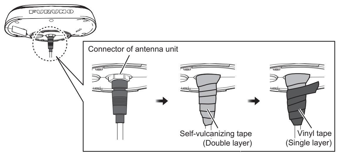
5. Wrap self-vulcanizing tape twice at the junction between connectors of the antenna unit and the antenna cable. Then wrap vinyl tape once over the self-vulcanizing tape for waterproofing.
Note: Wrap the tapes so as to cover both connectors of the antenna unit and the antenna cable.
6. Adjust the direction of the antenna unit so the bow mark on its base is facing the ship's bow.
Note: When the antenna unit is placed on the platform, make sure that the platform is not inclined.
1. INSTALLATION
7. Fasten the antenna unit to the mounting location with the three sets of supplied upset screws (M5×20, flat and spring washers attached) from the bottom through the mounting holes at step 2. After fastening the screws, coat the screw heads with the supplied adhesive.

Note: Screw length is dependent on the thickness of the mounting platform.
1.3 Pole Mount
Combine the antenna unit with the pole mount kit then attach the antenna unit assembly to the mounting pole.

1.3.1 Installation notices
- The diameter of the mounting pole must be 25 to 50 mm.
- Use the supplied pole mount kit and the supplied fixing support fixture for the pole mount installation so that the bow mark of the antenna unit faces to the bow.
- Select the correct clamp size of the pole mount kit fixture considering the diameter of the mounting pole.
| Name | Mast diameter | Remarks |
|---|---|---|
| Hose Clamp | For 20A to 25A (\phi25 to 35 mm) | Standard supply with CP20-04603 |
| For 32A to 40A ($35 to 50 mm) | Optional supply (OP20-52). |
• DO NOT apply the supplied adhesive to the four vent holes near the name plate.

1.3.2 Required tools
The following tools should be prepared in advance for this installation.
| Name | Remarks |
|---|---|
| Phillips-head Screwdriver | #2 |
| Slotted Head Screwdriver | For clamp bolts. |
| Wrench |
|
| Cable tie | Two pieces (at least), for fixing the antenna cable. |
| Putty | For securing the cable entrance of the pipe. |
1.3.3 How to assemble the pole mount kit
- 1. Thread the supplied lock nut onto the supplied pipe then tighten to the end of thread as shown in the figure below.
- 2. Apply the adhesive around the threads of the pipe then attach the pole mount texture to the pipe.
- 3. Turn the assembly upside down, hold the pipe steady and tighten the lock nut again with a wrench. The torque must be 15 N•m.

4. Wipe off the excess adhesive.
Note: Do not cover the five drain holes (shown in the figure below) with the adhesive.

1.3.4 How to mount the Antenna Unit
Set the hose clamps on the pole mount kit assembly and pass the antenna cable for NMEA 2000 through the pipe of the mast mounting kit from the underside. Note: Make sure the anchor point of the fixing support fixture faces upward.

2. Connect the antenna cable for NMEA 2000 to the connector of the antenna unit. Secure the antenna unit with the three supplied M5 screws from the underside. After fixing screws, coat the screw heads with the supplied adhesive.

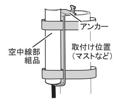
3. Set the antenna unit assembly to the mounting pole so that the anchor of the fixing support fixture is on the top of the mounting pole as shown in the figure at right.

4. Loosely hand tighten the hose clamps so that you easily adjust the position of the antenna later in this procedure.

5. Adjust the direction of the antenna unit so the bow mark is facing the ship's bow.

- 6. Fasten the hose clamps to fix the antenna unit.
- 7. Make a loop in the antenna cable, then fix the looped section to the pole as shown in the figure below.

8. Apply putty (local supply) to the cable exit, to secure the cable.
1.4 Roof Mount
The optional Roof Mount Kit (OP20-04602) is used to mount the antenna unit on the roof (overhead), with the fixing screws inserted from the top of the antenna unit.
1.4.1 Installation notices
- The mounting platform must be flat. Do not install the unit on an uneven surface.
- DO NOT apply the adhesive to the area between the roof mount kit and the mounting platform, or between the antenna unit and the roof mount kit. See step 9 on page 1-10 for details.
• DO NOT apply the adhesive to the four vent holes near the name plate.

1.4.2 Required tools
The following tools should be prepared in advance for this installation.
| Name | Remarks | |
|---|---|---|
| Hole Saw | For making the cable hole ($25 mm) | |
| File | For smoothing the cut edge of the cable hole | |
| Phillips-head Screwdriver | #2 | |
1.4.3 How to mount the Antenna Unit
- Construct a suitable mounting platform, minimum size 260 mm (bow-stern) × 240 mm. If corrosive material is used, take necessary anti-corrosion measures. Note: The mounting platform must be flat, level and firmly secured.
- Make a cable hole ($$\phi25±2 mm$) for passing the supplied antenna cable through the center of the mounting platform.
Note: The cable hole should be made according to the above specifications. An excessively large hole can result in water leakage. Alternatively, an excessively small hole can prevent cable routing.


260 mm (min.)
Cable hole
(ø25+2 mm)
-(bow-stern direction)-
4. Set the antenna unit on the roof mount kit so the bow marks for the antenna unit and the roof mount kit base are aligned.

5. Turn the antenna unit assembly upside-down, then secure the antenna unit to the kit base with the supplied three screws (M5×20).

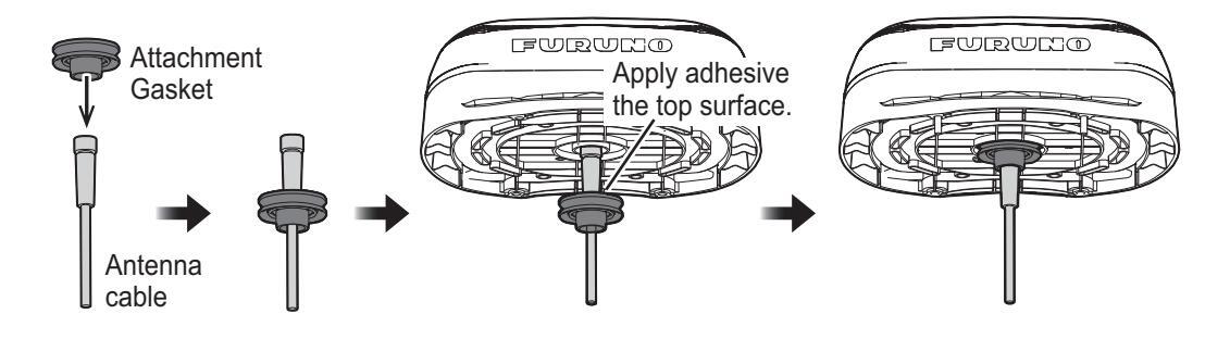
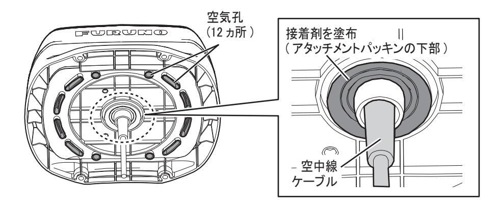
6. Attach the supplied attachment gasket to the antenna cable. Apply the supplied adhesive to top of the attachment gasket and then connect the antenna cable to the bottom of the antenna unit assembly.
Note 1: When attaching the gasket to the antenna cable, take note of the direction of the gasket referring to the figure below.
Note 2: Before attaching the gasket to the antenna unit, apply the supplied adhesive (TB5211) to the top surface of the gasket, where it contacts the antenna unit.
7. Apply the supplied adhesive (TB5211) to the bottom of the attachment gasket. Note: DO NOT apply the adhesive to the vent holes.

- 8. Set the antenna unit assembly so the bow mark (see step 4) on the top of the antenna unit is facing the ship's bow.
- Apply the supplied adhesive TB5211 to the threads of the supplied screws (M5×20), then fasten the antenna unit assembly with their screws from the top. Note: DO NOT apply the adhesive to the contact areas (Hashed areas in the figure below) between the roof mount kit and a mounting platform and between the antenna unit and the roof mount kit.

1.5 Antenna Mounting Base (option)
The antenna unit can be mounted on the following locations, using the optional right angle mounting base (NO.13-QA330).
- Inclined surface (adjustable up to 35°)
- Narrow, flat surface
151 Installation notices
- Do not install the unit on an uneven surface
- DO NOT apply the adhesive to the four vent holes near the name plate

1.5 2 Required tools
The following tools should be prepared in advance for this installation
| Name | Remarks |
|---|---|
| Electrical Drill | For making the mounting holes |
| Drill Bit | φ4.2 to 5 |
| Hole Saw | For making the cable hole ( |
| File | For smoothing the cut edge of the cable hole |
| Phillips-head Screwdriver | #2 |
153 How to mount the Antenna Unit
- 1. Attach the pole mount kit to the antenna base referring to subsection 1.3.3. Note: The pipe included in the pole mount kit is not used.
- 2. Set the antenna base to the mounting location considering the tilt direction, and make four mounting holes (64.2 to 5 mm) on the mounting platform.
Note: The possible tilt direction of the antenna base depends on the setting position of the antenna base

3. Make an antenna cable hole ( 25±2 mm) at the center of the four mounting holes for passing the supplied NMEA 2000 antenna cable through the mounting platform.

Cable hole (ø25±2 mm)
1. INSTALLATION
4. Pass the NMEA 2000 antenna cable through the mounting platform and the pipe of the antenna base from the underside of the antenna base.

5. Pull the pipe slightly upwards then apply the supplied adhesive to the inside and bottom face the antenna base footing.

6. Fit the antenna base to the platform so that the mounting holes are aligned with each other. Adjust the direction of the pipe while keeping in mind the fixing hole is pointed towards the ship's bow as illustrated below.


7. Remove hex socket head bolts one by one and fasten the supplied screws with adhesive loosely. After loosely fastening four screws, fasten them tightly then wipe off the excess adhesive. Note: The adhesive takes approximately 30 minutes to adhere.

8. Connect the NMEA 2000 antenna cable to the bottom of the antenna unit.

9 Secure the antenna unit with the supplied three M5 screws from the underside

10. Loosen the hex socket head bolts (see step 5) with the supplied hex key wrench then adjust the direction of antenna base so the bow mark on its base is facing the ship's bow. After adjusting, tighten the hex socket head bolts on the antenna base again.

1.6 Bird Deterrents (Option)
The optional bird deterrents (OP20-54) can help keep birds from resting on your antenna.
Remove the double-sided tape from two bird deterrents, then attach the deterrents to the antenna cover. Coat around the contact area of both bird deterrents with the supplied adhesive.

1.7 Snow Cover Kit (Option)
The optional Snow Cover Kit (OP20-53) is available to reduce snow build-up on your antenna.
To install this kit, see the instructions (C72-01901) supplied with the kit.
1.8 Wiring with Other Equipment
Using the supplied cable assembly, connect the antenna cable of this equipment to the NMEA 2000 network backbone. Refer to "SYSTEM CONFIGURATION" on page vi for details.
This equipment connects to the devices in an NMEA 2000 network.
- This equipment: 4 LEN at 9 V
- Connect equipment to the backbone with T-type connectors.
- Terminators are required for both ends of the backbone cable.
- We recommended that power from the NMEA 2000 network be input at the center of the backbone.
What is NMEA 2000 (CAN) bus?
CAN bus is a communication protocol (NMEA 2000 compliant) that shares multiple data and signals through a single backbone cable. You can simply connect any CAN bus devices onto the backbone cable to expand your network on-board. With CAN bus, IDs are assigned to all the devices in the network, and the status of each sensor in the network can be detected. All the CAN bus devices can be incorporated into the CAN bus network. For detailed information about CAN bus wiring, see "Furuno CAN bus Network Design Guide" (Type: TIE-00170).
Guideline for Connecting
Follow these guidelines when selecting a mounting location.
-
Where the cable connectors and NMEA 2000 connectors are subjected to moisture or water spray, waterproof the connectors as shown below.
- 1. Wrap the connection point with a single layer of vinyl tape.
- 2. Wrap one layer of self-bonding tape over the vinyl tape.
- 3. Wrap two layers of vinyl tape over the self-bonding tape.

1. INSTALLATION
This page is intentionally left blank.
2. INITIAL SETTINGS
When the unit is powered for the first time, it is in a "cold start" state, meaning there is no satellite data (almanac data) stored. In this state, the unit searches for, and stores, satellites to find its heading. This process takes approximately 60 seconds.
If the heading is not found within 30 minutes, the antenna installation location may not be suitable. Ensure an unobstructed path between the SCX-20 and satellites. Once a heading has been found, initial settings should be done.
If the installed heading error is found to be 5° or higher, physically turn the antenna while monitoring the heading indication to reduce the error as much as possible. Errors less than 5° can be adjusted in software.
Initial settings can be done via the NMEA 2000 network with one of the following methods:
-
Access the setting menu of the SCX-20 from compatible equipment
- TZTL12F/TZTL15F/TZT2BB: Software version must be "06.01" or later.
- NAVpilot-300: Software version of the control unit must be "01.07" or later, and software version of the processor unit must be "01.06" or later.
- TZT12F/TZT16F/TZT19F
See the operator's manual of the equipment used to access the SCX-20 for how to access the setting menu.
• Connect a PC and setup the SCX-20 using the SC setting tool
You can download the SC setting tool from the quick response code to the right. For how to use the SC setting tool, see the operator's manual of the SC setting tool (OME-72851).

Note 1: If the SCX-20 is re-booted, re-connection is required to access the SCX-20 menu.
Note 2: This manual provides descriptions for the SCX-20 setting menu that you can access from the compatible equipment. See the menu tree at the back of this manual for menu details.
Note 3: This manual uses the TZTL15F for menu examples and screenshots. Displayed data, menus and layouts may differ on your equipment.
2.1 [GNSS Setup] Menu
You can disable (ignore) satellites and adjust the elevation mask from the [GNSS Setup] menu.
| Menu item | Description | |||
|---|---|---|---|---|
| [Disable SV] | ||||
| [QZSS All] | Select [YES] to ignore all QZSS system satellites. | |||
| [QZSS] → [QZSS1] | You can ignore individual QZSS system satellites by specifying the satellite | |||
| [QZSS] → [QZSS2] | number. A maximum of three satellites can be ignored. | |||
| [QZSS] → [QZSS3] | Note: When [QZSS All] is set to [YES], the setting values for [QZSS1] to | |||
| [GPS All] | Select [YES] to ignore all GPS system satellites. | |||
| [GPS] → [GPS1] | You can ignore individual GPS system satellites by specifying the satellite | |||
| [GPS] → [GPS2] | number. A maximum of three satellites can be ignored. | |||
| [GPS] → [GPS3] | are automatically changed to "0" | |||
| Select [YES] to ignore all GLOINASS system satellites. | ||||
| [GLUNASS] → | You can ignore individual GLONASS system satellites by specifying the sat- | |||
| ellite number. A maximum of three satellites can be ignored. | ||||
| [GLONASS2] | Note: When [GLONASS All] is set to [YES], the setting values for [GLON- | |||
| [GLONASS] → | ASS1] to [GLONASS3] are automatically changed to "0". | |||
| [GLONASS3] | ||||
| [Galileo All] | Select [YES] to ignore all Galileo system satellites. | |||
| [Galileo] → [Galileo1] | You can ignore individual Galileo system satellites by specifying the satellite | |||
| [Galileo] → [Galileo2] | number. A maximum of three satellites can be ignored. | |||
| [Galileo] → [Galileo3] | Note: When [Galileo All] is set to [YES], the setting values for [Galileo1] to | |||
| • | [Galileo3] are automatically changed to "0". | |||
| [SV ELEV] | ||||
| [SV ELEV] | Adjust the elevation mask angle. This equipment does not track satellites | |||
| with an elevation angle lower than the angle set here. A higher elevation | ||||
| mask angle increases the positioning accuracy, but the number of the avail- | ||||
| an accurate position fix. | ||||
| [SBAS] | ||||
| [SBAS Mode] | Enable/disable the use of the SBAS system. | |||
| [SBAS Search] | Select [Auto] to search automatically for SBAS satellites, or [Manual] to man- | |||
| - | ually input the SBAS satellite number. | |||
| [SBAS Satellite Se- | Manually input the SBAS satellite number(s) you want to use. | |||
| lection] | Note: This item is only available when SBAS Search is set to Manual. | |||
| [Disable SBAS] | Select up to three SBAS satellites to ignore. | |||
| [Disable SBAS] → | ||||
| [SBAS1] | ||||
| [Disable SBAS] → | You can ignore SBAS satellites by specifying the satellite number. A maxi- | |||
| [SBAS2] | mum of three satellites can be ignored. | |||
| [Disable SBAS] → | ||||
| [SBAS3] | ||||
2.2 [Sensor] Menu
In order to display data correctly, enter the ship's dimensions, SCX-20 installation location and adjust the sensor offset values as required on the [Sensor] menu.
| Menu item | Description | ||||
|---|---|---|---|---|---|
| [Offset] | [Offset] | ||||
| [HDG] |
Offset the heading angle. When the heading angle is skewed right,
enter a negative value. When the heading angle is skewed left, en- ter a positive value. |
||||
| [Pitch] | Offset the pitch angle. | ||||
| [Roll] | Offset the roll angle. | ||||
|
[SOG/3-Axis
Speed] |
Offset the speed value. | ||||
| [Air Pressure] | Offset the air pressure value. | ||||
| [Air Temperature] | Offset the air temperature value. | ||||
| [Smoothing] | |||||
| [SOG/COG] | Set the time delay (smoothing) for SOG/COG data output. | ||||
| [3-Axis Speed] | Set the time delay (smoothing) for 3-Axis Speed data output. | ||||
| [ROT] | Set the time delay (smoothing) for ROT data output. | ||||
| [DR Time] | |||||
| [DR Time] | When the SCX-20 cannot receive the signal from the satellite, the SCX-20 continues to output heading data as "dead reckoning" for the time set here. If the signal from the satellite cannot be retrieved with in the time set here, the SCX-20 stops outputting the heading data. | ||||
| [Ship Size, ANT/CA | LC-SPD Position] | ||||
|
Enter the appropria
of the 3-axis speed sition of the 3-axis s |
te value according to the ship's size,
to improve the accuracy
d . The reference position for installation location and calculating po- speed is shown in the following figure: |
||||
|
Z (+
tubient since since position (0.0) |
)
) Draft position X (-) Uraft position X (-) Construction Ship bottom line Ship's length Construction N (+) Construction Ship's length Construction Construction Construction Construction Construction Construction Construction Construction Construction Construction Construction Construction Construction Construction Construction Construction Construction Construction Construction Construction Construction Construction Construction Construction Construction Construction Construction Construction Construction Construction Construction Construction Construction Construction Construction Construction Construction Construction Construction Construction Construction Construction Construction Construction Construction Construction Construction Construction Construction Construction Construction Construction Construction Construction Construction Construction Construction Construction Construction Construction Construction Construction Construction Construction Construction Construction Construction Construction Construction Construction Construction Construction Construction Construction Construction Construction Construction Construction Construction Construction Construction Construction Construction Construction Construction Construction Construction Construction Construction Construction Construction Construction Construction Construction Construction Construction Construction Construction Construction Construction Construction Construction Construction Construction Construction Construction Construction Construction Construction Construction Construction Construction Construction Construction Construction Construction Construction Construction Construction Construction Construction Construction Construction Construction Construction Construction Construction Construction Construction Construction Construction Construction Construction Construction Construction Constr |
||||
| [Ship's Width] | Set the ship's width, calculated from the port-side to starboard-side of the widest section of the vessel (Setting range: 1.0 to 999.9 m). | ||||
| [Ship's Length] | Set the ship's length, calculated to the bow-tip to the stern, along the center of the vessel (Setting range: 1.0 to 999.9 m). | ||||
| [Ship's Height] | Set the ship's height, calculated to the bottom of the keel to the top f the mast (Setting range: 1.0 to 199.9 m). | ||||
| Menu item | Description |
|---|---|
| [ANT Position X0] |
Set the port-starboard (Lateral) location of the SCX-20. Enter neg-
ative value for port-side, positive value for starboard-side. The cen- ter of the vessel is "0" (Setting range: -327.64 to +327.64 m). |
| [ANT Position Y0] | Set the bow-stern (Longitudinal) location of the SCX-20. Set the distance from the bow to the stern with the bow as 0 m (Setting range: 0.0 to 999.9 m). |
| [ANT Position Z0] | Set height of the SCX-20, from the bottom of the ship (Setting range: 0.0 to 199.9 m). |
|
[CALC-SPD-
POSN Y1 (BOW)] |
Set the bow-stern location for calculating the 3-axis speed. Ship's speed can be measured at two locations in addition to the antenna |
|
[CALC-SPD-
POSN Y2 (Stern)] |
|
|
[CALC-SPD-
POSN Z (Height)] |
Set the height for calculating the 3-axis speed. Enter the distance
from the bottom of the ship to the position where you want to mea- sure the ship's speed. For example, enter the draft value when you want to measure the speed at draft position. |
2.3 [Input/Output] Menu
You can enable/disable PGN output from the SCX-20 and adjust transmission rate on the [Input/Output] menu.
The following table shows the PGNs that the SCX-20 outputs and transmission rate is adjustable. If you want to disable the PGN, set the transmission rate to "Off". The setting range changes according to the PGN. For the setting range of each PGN, see the menu tree at the back of this manual.
Note: Normally, keep the default setting. If there is a need to change the transmission rate, only change the rate for necessary PGNs. An excessive number of PGNs with a low transmission rate can cause problems with PGN output and transmission rates.
| PGN | PGN name | PGN | PGN name |
|---|---|---|---|
| 065280 | Heave | 129540 | GNSS Sats in View |
| 126992 | System Time | 130310 | Environmental Parameters |
| 126993 | Heartbeat | 130312 | Temperature |
| 127250 | Vessel Heading | 130314 | Actual Pressure |
| 127251 | Rate of Turn | 130316 | Temperature, Extended Range |
| 127252 | Heave | 130577 | Direction Data |
| 127257 | Attitude | 130578 | Vessel Speed Components |
| 127258 | Magnetic Variation | 130842 | Six Degrees of Freedom Move- |
| 129025 | Position, Rapid Update | 130843 | Heel Angle and Roll Information |
| 129026 |
COG and SOG, Rapid Up-
date |
130845 | Multi Sats In View Extended |
| 129029 | GNSS Position Data | 130846 | Motion Sensor Status |
| 129539 | GNSS DOPs | Extended |
2.4 [System] Menu
You can check the system information, perform diagnostic tests and restore the factory defaults from the [System] menu.
| Menu item | Description | |||
|---|---|---|---|---|
| [System Information] | ||||
| [Main PCB] | Main board version. | |||
| [Starter Version] | Starter application software version. | |||
| [Booter 1 Version] | Booter 1 application software version. | |||
| [Booter 2 Version] | Booter 2 application software version. | |||
| [Application Version] | Main application software version. | |||
| [Serial No.] | Serial number for your SCX-20. | |||
| [GNSS 1] | GNSS cores (1 to 4) software version. | |||
| [GNSS 2] | ||||
| [GNSS 3] | ||||
| [GNSS 4] | ||||
| [CAN Unique Number] | CAN unique ID for the SCX-20. | |||
| [CAN Address] | CAN address assigned to the SCX-20. | |||
| [Powered Time] | Time since the SCX-20 was last turned on. | |||
| [Overall Powered Time] | Total operation time of the SCX-20. | |||
| [Simple Diagnostic Test] | ||||
| [ROM] | ROM test result (OK or NG (No Good)). | |||
| [RAM] | RAM test result (OK or NG (No Good)). | |||
| [Rate Gyro Status] | Rate gyro status (Good or Bad). | |||
| [Accelerometer Status] | Accelerometer status (Good or Bad). | |||
| [Magnetic Sensor Status] | Magnetic sensor status (Good or Bad). | |||
| [Press./Temp. Sensor Status] | Air pressure/temperature sensor status (Good or Bad). | |||
| [Installation Status] | Show the number of excessive vibrations detected at the installation location. | |||
| [GNSS 1 Status] | GNSS 1 thru 4 status (Good or Bad). | |||
| [GNSS 2 Status] | ||||
| [GNSS 3 Status] | ||||
| [GNSS 4 Status] | ||||
| [Antenna 1 Status] | Antenna 1 thru 4 status (Good or Bad). | |||
| [Antenna 2 Status] | ||||
| [Antenna 3 Status] | ||||
| [Antenna 4 Status] | ||||
| Menu item | Description | ||
|---|---|---|---|
| [Advanced Diagnostic Test] | |||
| [ROM] | Shows the test results for | each item (OK or NG (No | |
| [RAM] | Good)). | ||
| [Rate Gyro Test] | Note: This test automatica | ally checks each item and | |
| [Accelerometer Test] | aata output stops during ti | ie iesi. | |
| [GNSS 1 RAM Test] | |||
| [GNSS 1 ROM Test] | |||
| [GNSS 2 RAM Test] | |||
| [GNSS 2 ROM Test] | |||
| [GNSS 3 RAM Test] | |||
| [GNSS 3 ROM Test] | |||
| [GNSS 4 RAM Test] | |||
| [GNSS 4 ROM Test] | |||
| [Reset Setting] | |||
| [Menu Settings] |
Select [YES] to restore
all user set menu settings to their default. Reboot the SCX-20 to complete the procedure. |
Note:
Almanac data is
also reset with this proce- dure, correct positioning will not be available until sufficient satellite data is |
|
| [Factory Reset] |
Select [YES] to restore
the SCX-20 to factory de- fault. Reboot the SCX-20 to complete the procedure. |
re-obtained. | |
| [Restart] | |||
| [System Restart] |
Select [YES] to restart the SCX-20.
Note: All data output from the SCX-20 stops when [YES] is selected. This procedure should only be done when safely moored. |
||
3. MAINTENANCE
3.1 Preventative Maintenance
The following preventative maintenance and checks are important for good performance.
| Item to check | Points to check | Remedy |
|---|---|---|
| Connectors |
Check that the connec-
tors are firmly connect- ed. |
Reconnect loosened cables. |
|
Cable run
(cabling) |
Visually check the cables for wear and tear or damage. | Consult your dealer for cable replacement. |
| Cover | Cleanliness of the cover |
Dust can be removed with a soft cloth. Do
not use chemical-based cleaners or sol- vents as they can remove paint/markings and cause the cover to deform. |
3.2 Troubleshooting
This section covers possible problems which may arise while using the SCX-20 and how to address each problem.
| Problem | Possible cause | Remedy |
|---|---|---|
| Data is not received from the SCX-20. |
Cable is disconnected,
damaged, or faulty. |
Check the SCX-20 cable
connectors are firmly con- nected. Check that the ca- ble is not damaged or severed. Also confirm that the CAN bus is powered and functioning normally. Contact your local dealer for service as required. |
| Incorrect settings at the display. |
Refer to the Multi-Function
Display unit's manual and adjust the settings as re- quired. |
|
|
Data (heading, etc.) shown
on the screen is not correct. |
|
|
|
Position data is not re-
ceived. |
GLONASS is set for ANT 4. |
GLONASS is NOT applied
to ANT4. For GLONASS, select ANT1 to ANT3. |
3. MAINTENANCE
This page is intentionally left blank.
APPENDIX 1 MENU TREE
This appendix covers the SCX-20 menu, accessible from compatible equipment. For the SC setting tool menu tree, see the operator's manual for the SC setting tool (OME-72851). Contact our dealer for details.

• Continued from the previous page
| - Input/Output - PGN* |
065280 (Off, 20, 25, 50,
100
, 200, 1000, 2000) [ ]
126992 (Off, 1000 , 2000) [ ] |
|---|---|
|
*: PGN settings use
miliseconds (ms) as their unit of measurement. |
126993 (Off, 60000) [ ] |
| System System Information |
Main PCB (Display only) [ ]
Starter Version (Display only) [ ] Booter1 Version (Display only) [ ] Booter2 Version (Display only) [ ] Application Version (Display only) [ ] GNSS 1 (Display only) [ ] GNSS 2 (Display only) [ ] GNSS 3 (Display only) [ ] GNSS 4 (Display only) [ ] CAN Unique Number (Display only) [ ] Powered Time (Display only) [ ] Overall Powered Time (Display only) [ ] |
Continued from the previous page Simple — - ROM (OK, NG) [ Diagnostic -RAM (OK, NG) Test -Rate Gvro Status (Good, Bad) [ - Accelerometer Status (Good, Bad) [ - Magnetic Sensor Status (Good, Bad) - Press./Temp. Sensor Status (Good, Bad) - Installation Status (0 to 99) - GNSS 1 Status (Good, Bad) - GNSS 2 Status (Good, Bad) - GNSS 3 Status (Good, Bad) - GNSS 4 Status (Good, Bad) - Antenna 1 Status (Good, Bad) [ - Antenna 2 Status (Good, Bad) [ - Antenna 3 Status (Good Bad) – Antenna 4 Status (Good, Bad) Advanced -- ROM (OK, NG) [ Diagnostic -RAM (OK, NG) Test - Rate Gvro Test (OK, NG) - Accelerometer Test (OK, NG) [ - GNSS 1 RAM Test (OK, NG) - GNSS 1 ROM Test (OK, NG) - GNSS 2 RAM Test (OK, NG) [ - GNSS 2 ROM Test (OK, NG) [ — GNSS 3 RAM Test (OK, NG) [ - GNSS 3 ROM Test (OK, NG) - GNSS 4 RAM Test (OK NG) [ - GNSS 4 ROM Test (OK, NG) Reset - Menu Settings (YES, NO) Settina Factory Reset (YES, NO) [ Restart ———— System Restart (YES, NO) [
APPENDIX 2 GEODETIC CHART CODES
| 001: WGS84 | 091: | NORTH AMERICAN 1927 | Bahamas (excl. San Salvador Is.) | |
| 002: WGS72 | Maan Value (Janan Karaa & Okinawa) | 092: | NORTH AMERICAN 1927 | Bahamas, San Salvador Is. |
| Mean Value (CONUS) | 093 | NORTHAMERICAN 1927 (Cont'd): | Canada (Incl. Newfoundland Is.) | |
| · Mean Value | 094 | NORTH AMERICAN 1927 (Cont d): | East Canada | |
| 006: AUSTRALIAN GEODETIC 1984 | : Australia & Tasmania | 090. | NORTH AMERICAN 1927 (Cont'd): | Manitoba & Ontario |
| : Mean Value (Ethiopia & Sudan) | 090 | NORTH AMERICAN 1927 (Cont'd): | Northwest Territories & Saskatchewan | |
| : Ethiopia | 098 | NORTH AMERICAN 1927 (Cont'd): | ||
| 009: ADINDAN | : Mali | 099 | NORTH AMERICAN 1927 (Cont'd): | Canal Zone |
| 010: ADINDAN | : Senegal | 100: | NORTH AMERICAN 1927 (Cont'd) | Caribbean |
| 011: ADINDAN | : Sudan | 101: | NORTH AMERICAN 1927 (Cont'd): | Central America |
| 012: AFG | : Somalia | 102: | : NORTH AMERICAN 1927 (Cont'd): | Cuba |
| 013: AIN EL ABD 1970 | : Bahrain Is. | 103: | : NORTH AMERICAN 1927 (Cont'd): | Greenland |
| 014: ANNA 1 ASTRO 1965 | : Cocos Is. | 104: | : NORTH AMERICAN 1927 (Cont'd): | Mexico |
| 015: ARC 1950 | : Mean value | 105: | NORTH AMERICAN 1983 | Alaska |
| 016: ARC 1950 | Botswana | 106: | NORTH AMERICAN 1983 | Canada |
| 017: ARC 1950 |
Lesotno
Melowi |
107: | NORTH AMERICAN 1983 | CONUS |
| 018: ARC 1950 |
. Malawi
: Swaziland |
108: | NORTHAMERICAN 1983 | Mexico, Central America |
| 019: ARC 1950 | · Zaire | 109 | OBSERVATORIO 1966 | Corvo & Flores Is. (Azores) |
| 020. ARC 1950 | · Zambia | 110: | ||
| 021. ARC 1950 | Zimbabwe | 112 | ||
| 023: ARC 1950 | : Mean Value (Kenva & Tanzania) | 112. | Kauai | |
| 024 ARC 1960 | : Kenya | 114 | OLD HAWAIIAN | Maui |
| 025: ARC 1960 | : Tanzania | 115: | OLD HAWAIIAN | Oahu |
| 026: ASCENSION IS, 1958 | : Ascension Is. | 116: | OMAN | Oman |
| 027: ASTRO BEACON "E" | : Iwo Jima Is. | 117: | ORDNANCE SURVEY OF GREAT BRITA | AIN 1936: Mean Value |
| 028: ASTRO B4 SOR. ATOLL | : Tern Is. | 118: | ORDNANCE SURVEY OF GREAT BRITA | AIN 1936: England |
| 029: ASTRO POS 71/4 | : St. Helena Is. | 119: | ORDNANCE SURVEY OF GREAT BRITA | AIN 1936: England, Isle |
| 030: ASTRONOMIC STATION 1952 | : Marcus Is. | of Man & Wales | ||
| 031: AUSTRALIAN GEODETIC 1966 | : Australia & Iasmania | 120: | : ORDNANCE SURVEY OF GREAT BRITA | AIN 1936: Scotland & |
| 032: BELLEVUE (IGN) | Elate & Erromango Is. | Shetland Is. | ||
| 121: | AIN 1936 : Wales | |||
| 122 | Diteoire le | |||
| 035. CANFO INCHAUSPE | 123. |
. Fillailli IS.
1962: South Chilo (near 52°S) |
||
| 037: CAPE | South Africa | 124. | 1905. South Chile (flear 55 5) | |
| 038 CAPE CANAVERAL | : Mean Value (Florida & Bahama Is.) | 126 | V 1956: Bolivia | |
| 039: CARTHAGE | : Tunisia | 127 | PROVISIONAL SOUTH AMERICAN | N 1956: Chile-Northern Chile |
| 040: CHATHAM 1971 | : Chatham Is. (New Zealand) | (near 19°S) | ||
| 041: CHUA ASTRO | : Paraguay | 128: | PROVISIONAL SOUTH AMERICA | AN 1956: Chile-Southern Chile |
| 042: CORREGO ALEGRE | : Brazil | (near 43°S) | ||
| 043: DJAKARTA (BATAVIA) | : Sumatra Is. (Indonesia) | 129 | V 1956: Columbia | |
| 044: DOS 1968 | : GIZO IS. (New Georgia IS.) | 130 | N 1956: Ecuador | |
| 045: EASTER IS. 1967 | . Edstern Furone | 131: | PROVISIONAL SOUTH AMERICAN | N 1956: Guvana |
| 046: EUROPEAN 1950 (Cont d) | 132 | PROVISIONAL SOUTH AMERICAN | N 1956: Peru | |
| 048: EUROPEAN 1950 (Cont'd) | : Equpt | 133: | PROVISIONAL SOUTH AMERICAN | N 1956: Venezuela |
| 049: EUROPEAN 1950 (Cont'd) | England Scotland Channel & Shetland Is | 134: | : PUERTO RICO : | : Puerto Rico & Virgin Is. |
| 050: EUROPEAN 1950 (Cont'd) | England, Ireland, Scotland & Shetland Is. | 135: | : QATAR NATIONAL : | Qatar |
| 051: EUROPEAN 1950 (Cont'd) | : Greece | 136: | QORNOQ | South Greenland |
| 052 EUROPEAN 1950 (Cont'd) | : Iran | 137 | ROME 1940 | : Sardinia Is. |
| 053: EUROPEAN 1950 (Cont'd) | : Italy, Sardinia | 138 | Sao Miguei, Santa Maria IS. (Azores) | |
| 054: EUROPEAN 1950 (Cont'd) | : Italy, Sicily | 140 |
: Esplitio Santo Is.
: East Falkland Is |
|
| 055: EUROPEAN 1950 (Cont'd) | 141 | SOUTH AMERICAN 1969 | Mean Value | |
| 056: EUROPEAN 1950 (Cont d) | Moon Value | 142 | SOUTH AMERICAN 1969 | Argentina |
| 143 | SOUTH AMERICAN 1969 | Bolivia | ||
| · New Zealand | 144 | SOUTH AMERICAN 1969 | Brazil | |
| 060: GLIAM 1963 | Guam Is | 145: | SOUTH AMERICAN 1969 | Chile |
| 061: GUX 1 ASTRO | : Guadalcanal Is. | 146: | SOUTH AMERICAN 1969 | : Columbia |
| 062: HJORSEY 1955 | : Iceland | 147: | SOUTH AMERICAN 1969 | Ecuador |
| 063: HONG KONG 1963 | : Hong Kong | 148: | SOUTH AMERICAN 1969 | Guyana |
| 064: INDIAN | : Thailand & Vietnam | 149: | SOUTH AMERICAN 1969 | Paraguay |
| 065: INDIAN | : Bangladesh, India & Nepal | 150 | SOUTH AMERICAN 1969 | |
| 066: IRELAND 1965 | : Ireland | 151 | ||
| 067: ISTS 073 ASTRO 1969 | : Diego Garcia | 152 | ||
| 068: JOHNSTON IS. 1961 | Sri Lonko | 154 | SOUTHEAST BASE | Porto Santo & Madeira Is |
| 155 | SOUTHWEST BASE | Faial, Graciosa, Pico, Sao Jorge & Terceria Is | ||
|
070. KERGUELEN 15.
071: KERTALI 1048 |
· West Malavsia & Singanore | 156: | TIMBALAI 1948 | Brunei & East Malavsia (Sarawak & Sabah) |
| 072: LA RELINION | : Mascarene Is. | 157: | TOKYO | : Japan |
| 073 L C 5 ASTRO | : Cavman Brac Is. | 158: | : TOKYO : | Korea |
| 074: LIBERIA 1964 | : Liberia | 159: | : TOKYO : | : Okinawa |
| 075: LUZON | : Philippines (excl. Mindanao Is.) | 160: | TRISTAN ASTRO 1968 | Tristan da Cunha |
| 076: LUZON | : Mindanao Is. | 161: | : Viti Levu Is. (Fiji Is.) | |
| 077: MAHE 1971 | : Mahe Is. | 162 | : Iviarshall IS. | |
| 078: MARCO ASTRO | : Salvage Islands | 103 | Bangka & Belitung la (Indonasia) | |
| U/9: MASSAWA | : Entrea (Ethiopia) | 165 | Camp Momurdo Area Antarctica | |
| Midway Is | 166 | G. SEGARA | Kalimantan Is. (Indonesia) | |
| · Midway is. | 167 | HERAT NORTH | Afghanistan | |
| : Masirah Is. (Oman) | 168 | HU-TZU-SHAN | Taiwan | |
| 084 NAHRWAN | : United Arab Emirates | 169 | TANANARIVE OBSERVATORY 1925 | Madagascar |
| 085: NAHRWAN | : Saudi Arabia | 170: | YACARE | Uruguay |
| 086: NAMIBIA | : Namibia | 171: | RT-90 | Sweden |
| 087: MAPARIMA, BWI | : Trinidad & Tobago | 172: | : CK42 (PULKOVO 1942) | : Russia |
| 088: NORTH AMERICAN 1927 | : Western United States | 173 | ||
| 089: NORTH AMERICAN 1927 | : Eastern United States | 175 | CK95 |
. Russia
Russia |
| U9U: NORTH AMERICAN 1927 | - Alaska | 175. |
APPENDIX 3 WHAT IS SBAS?
A satellite-based augmentation system, or SBAS (Satellite Based Augmentation System), is an augmentation system that uses additional messages from satellite broadcasts to support regional and wide area augmentation. SBAS provides GPS signal corrections to SBAS users, for even better position accuracy, through the GPS error corrections that are widely broadcasted from the geostationary satellite.
SBAS is used in America, Europe, Japan and India. These four systems; WAAS, EGNOS, MSAS and GAGAN, have interoperability. The illustration below shows the coverage area for each provider. This manual uses "SBAS" for these four providers generically.
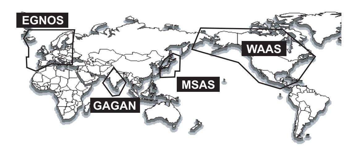
| Provider | Satellite type | Longitude | Satellite No. |
|---|---|---|---|
| WAAS | Intelsat Galaxy XV | 133°W | 135 |
| (Wide Area Augmentation System, | TeleSat Anik F1R | 107.3°W | 138 |
| America) | Inmarsat-4-F3 | 98°W | 133 |
| EGNOS | Inmarsat-3-F2/AOR-E | 15.5°W | 120 |
|
(Euro Geostationary Navigation
Overlay Service, Europe) |
Artemis | 21.5°E | 124 |
| Inmarsat-4-F2 | 25°E | 126 | |
| SES-5 | 5°E | 136 | |
| MSAS | MTSAT-1R | 140°E | 129 |
|
(Multi-Functional Satellite Aug-
mentation System, Japan) |
MTSAT-2 | 145°E | 137 |
| GAGAN | GSAT-8 | 55°E | 127 |
|
(GPS And GEO Augmented Navi-
gation, India) |
GSAT-10 | 83°E | 128 |
FURUNO
SPECIFICATIONS OF SATELLITE COMPASS SCX-20
1 GENERAL
| 1.1 | Receiving frequency | 1575.42 MHz (GPS/Galileo/QZSS/SBAS), |
|---|---|---|
| 1 2 | Tracking code |
1002.3023 MITZ (GEONASS)
C/A code (CPS/OZSS/SRAS) E1R (Calileo) | 10E (CLONASS) |
| 1.2 | C/A CODE (GF3/QZ33/SBAS), ETB (Gailled), LTOF (GLONASS) | |
| 1.5 | Allilude resolution | 1.0° rma (atatia) 0.5° rma (dynamia) |
| 1 1 | Tracking bearing | |
| 1.4 | ||
| 1.5 | Heave accuracy | 5 cm (10) |
| 1.6 | 60 s approx. | |
| 1.7 | 5 m approv. (2drms. HDOP<1) | |
| MSAS | 4 m approx. (2drms, HDOP<4) | |
| WAAS | 3 m approx. (2drms, HDOP<4) | |
| 1.8 | Position fixing time | 50 s approx. |
| 1.9 | Update interval | Attitude: 50 Hz max, Position: 10 Hz max. |
| 1.10 |
,
Ship's speed accuracy |
|
| - | SOG | 0.02 kn rms (tracking satellites 5 or more) |
| 0.2 kn rms (tracking satellites 3 or 4) | ||
| VBW (speed on around) | 0.02 kn rms (tracking satellites 5 or more, at antenna position) | |
| (.p | 0.08 kn rms (tracking satellites 5 or more, at another position) | |
| 2.0% of shin's speed or 0.2 kn whichever is the greater | ||
| (tracking satellites 3 or 4) | ||
| 1 | Atmosphere sensor | |
| Pressure | 850 to 1100 bPa (temperature range: 0 to +50°C) | |
| accuracy: +1 0 hPa (offset adjustment) | ||
| Temperature | -20°C to +55°C (relative wind: 4 kn or more) | |
| remperature | accuracy: +2.0°C (offset adjustment) | |
| 2 | INTERFACE | |
| 2.1 | Number of ports | NMEA2000: 1 port |
| 2.2 | NMEA2000 PGN | |
| Input | 059392/904, 060160/416/928, 061184, 065240, 126208/720, 130847 | |
| Output | 059392/904, 060928, 061184, 065280, 126208/464/720/992/993, | |
| 126996/998, 127250/251/252/257/258, 129025/026/029/538/539/540 | ||
| 130310/312/314/316/577/578/816/817/818/819/822/823/833/834, | ||
| 130842/843/845/846/847 | ||
| 3 | POWER SUPPLY | |
| 12-24 VDC (10.8-31.2V): 0.2-0.1 A (LEN: 4 at 9 V) | ||
| Δ | ||
| 4 1 | -25°C to +55°C (storage: -30°C to +70°C) | |
| 42 | Relative humidity | 95% or less at +40°C |
|
т.
с
Л २ |
||
|
н.Э
Л Л |
Vibration | |
| -+.+ | VIDIALIUII |
5 UNIT COLOR
N9.5
重要なお知らせ
- マニュアル記載内容の一部または全部の転載、複写は著作権者である当社の許諾 が必要です。無断転載することを固くお断りします。
- 製品の仕様ならびにマニュアルの内容は予告なく変更することがあります。
- 画面に表示される内容は、システムの設定や動作状態によって異なります。した がって、マニュアル内に掲載してあるイラストは画面の表示と異なる場合があり ます。
- お客様がマニュアルの内容に従わずに本機または本ソフトウェアを取り扱われたり、または当社および当社指定の者以外の第三者により改造・変更されることに起因して生じる障害等については、当社は責任を負いかねますのでご了承ください。
- お買い上げの機器を廃棄するときは、産業廃棄物として地方自治体の条例または 規則に従って処理してください。詳しくは、各地方自治体に問い合わせてください。
- マニュアルに記載されている社名、製品名は、一般に各開発メーカーの登録商標 または商標です
▲ 安全にお使いいただくために
必ずお守りください
お使いになる人や他の人への危害、財産への損害を未然に防止するため、以下のことを必ずお守り ください。表示内容を無視して誤った使い方をしたときに生じる危害や、損害の程度を本書では次の 表示で区分し、説明していますので十分に気をつけてください。

装備上の安全事項

取扱い上の安全事項

目次
| システム構成 vi 構成表 vii 1章 取付け 1-1 1.1 装備上の注意 1-1 1.2 平面装備 1-2 1.2.1 必要な工具 1-2 1.3.1 装備上の注意 1-4 1.3.2 必要な工具 1-4 1.3.3 ボールマウント装備 1-4 1.3.1 装備上の注意 1-4 1.3.2 必要な工具 1-5 1.3.3 ボールマウント装備 1-6 1.4 ルーフマウント装備 1-7 1.4.1 装備上の注意 1-7 1.4.2 必要な工具 1-6 1.4 ルーフマウント装備 1-7 1.4.3 取付け 1-8 1.5 アンテナベース装備 (オブション) 1-10 1.5.1 装備上の注意 1-10 1.5.2 必要な工具 1-10 1.5.3 取付け 1-11 1.6 高除け (オブション) 1-13 1.7 積雪かバー (オブション) 1-13 1.8 NMEA 2000 機器との接続 1-13 1.7 積雪かバー (オブション) 1-13 1.8 NMEA 2000 機器との接続 1-13 2.4 [System] メニュー 2-2 2.3 [Input/Output] メニュー 2-5 3.4 [ | はじめ | V | |
|---|---|---|---|
| 構成表 vii 1章 取付け 1-1 1.1 装備上の注意 1-1 1.2 甲面装備 1-2 1.2.1 必要な工具 1-2 1.3.1 装備上の注意 1-4 1.3.2 必要な工具 1-5 1.3.3 ボールマウント装備 1-4 1.3.2 必要な工具 1-5 1.3.3 ボールマウントキットの組立て 1-6 1.4 ルーフマウント装備 1-7 1.4.1 装備上の注意 1-7 1.4.2 必要な工具 1-6 1.4 ルーフマウント装備 1-7 1.4.2 必要な工具 1-6 1.4 ルーフマウント装備 1-7 1.4.2 必要な工具 1-7 1.4.3 取付け 1-8 1.5 アンテナベース装備 (オブション) 1-10 1.5.3 取付け 1-11 1.6 鳥除け (オブション) 1-13 1.7 積雪が(- (オブション) 1-13 1.8 NMEA 2000 機器との接続 1-13 1.7 積雪が(- (オブション) 1-13 1.8 NMEA 2000 機器との接続 1-13 1.8 NMEA 2000 機器との接続 1-13 2.9 [Renor] メニュー 2-3 | システ | - ム構成 | vi |
| 1章 取付け | 構成表 | ₹ | vii |
| 1.1 装備上の注意 1-1 1.2 平面装備 1-2 1.2.1 必要な工具 1-2 1.2.2 取付け 1-2 1.3.1 装備上の注意 1-4 1.3.2 必要な工具 1-5 1.3.3 ボールマウント装備 1-4 1.3.2 必要な工具 1-5 1.3.3 ボールマウントキットの組立て 1-6 1.4 ルーフマウント装備 1-7 1.4.1 装備上の注意 1-7 1.4.2 必要な工具 1-8 1.4.3 取付け 1-8 1.5 アンテナベース装備(オブション) 1-10 1.5.2 必要な工具 1-10 1.5.2 必要な工具 1-10 1.5.3 取付け 1-8 1.5 アンテナベース装備(オブション) 1-11 1.6 鳥除け(オブション) 1-10 1.5.2 必要な工具 1-11 1.6 鳥除け(オブション) 1-13 1.7 積雪から( イブション) 1-13 1.8 NMEA 2000 機器との接続 1-13 2.9 装備後の設定 2-1 2.1 [GNSS Setup] メニュー 2-3 2.3 【Input/Otyped/y ニュー 2-5 2.4 [System] メニュー 2-5 2.4 [System] メニュー 2-5 | 1章 | 取付け | 1-1 |
| 1.2 平面装備 1-2 1.2 取付け 1-2 1.2 取付け 1-2 1.3 ボールマウント装備 1-4 1.3.1 装備上の注意 1-4 1.3.2 必要な工具 1-5 1.3.3 ボールマウントキットの組立て 1-5 1.3.4 取付け 1-6 1.4 ルーママウント装備 1-7 1.4.1 装備上の注意 1-7 1.4.1 装備上の注意 1-7 1.4.2 必要な工具 1-8 1.4.3 取付け 1-8 1.5 アンテナベース装備 1-7 1.4.2 必要な工具 1-10 1.5.1 装備上の注意 1-10 1.5.2 必要な工具 1-10 1.5.3 取付け 1-11 1.6 鳥除け (オブション) 1-11 1.6 鳥除け (オブション) 1-13 1.7 積雪力バー (オブション) 1-13 1.8 NMEA 2000 機器との接続 1-13 1.8 NMEA 2000 機器との接続 1-13 2.9 装備後の設定 2-1 2.1 [Shesori メニュー 2-5 | 1.1 装備上の注意 | 1-1 | |
121 必要な工具
1-2
1.2 取付け
1-2
1.3 ポールマウント装備
14
1.3.1 装備上の注意
14
1.3.2 必要な工具
15
1.3.3 ボールマウントキットの組立て
15
1.3.3 ボールマウント装備
17
1.4 ルーフマウント装備
17
1.4 レーフマウント装備
17
1.4 装備上の注意
17
1.4 数価なり注意
18
1.5 アンテナベース装備(オブション)
110
1.5.2 必要な工具
110
1.5.3 取付け
18
1.6 鳥除け (オブション)
113
1.7 積雪カバー (オブション)
113
1.8 NMEA 2000 機器との接続
113
2 草 装備後の設定
21
2.1 [ONSS Setup] メニュー
23
2.3 [Input/Output] メニュー
24
2 [Sensor] メニュー
25
2 4 [System] メニュー
|
|
1.2 平面装備
|
1-2
|
|
| 1.22 取付け 1-2 1.3 ボールマウント装備 14 1.3.1 装備上の注意 14 1.3.2 必要な工具 1-5 1.3.3 ボールマウントキットの組立て 1-5 1.3.4 取付け 1-6 1.4 ルーフマウント装備 1-7 1.4.1 装備上の注意 1-7 1.4.2 必要な工具 1-8 1.4.3 取付け 1-8 1.5 アンテナベース装備 1-10 1.5.1 装備上の注意 1-10 1.5.2 必要な工具 1-10 1.5.3 取付け 1-10 1.5.3 取付け 1-10 1.5.1 装備上の注意 1-10 1.5.3 取付け 1-11 1.6 鳥除け オブション) 1-13 1.7 積雪が(- (オブション) 1-13 1.8 NMEA 2000 機器との接続 1-13 2.9 装備後の設定 2-1 2.1 [GNSS Setup] メニュー 2-3 2.3 [Input/Output] メニュー 2-5 2.4 [System] メニュー 2-5 3.1< | 1.2.1 必要な工具 | 1-2 | |
| 1.3 ボールマウント装備 1.4 1.3.1 装備上の注意 1.4 1.3.2 必要な工具 1.5 1.3.3 ボールマウントキットの組立て 1.5 1.3.4 取付け 1.6 1.4 ルーママウント装備 1.7 1.4.1 装備上の注意 1.7 1.4.2 必要な工具 1.8 1.4.3 取付け 1.8 1.5 アンテナベース装備 (オプション) 1.10 1.5.1 装備上の注意 1.7 1.5.2 必要な工具 1.10 1.5.3 取付け 1.11 1.6 烏除け(オブション) 1.13 1.7 積雪力バー(オブション) 1.13 1.7 積雪力バー(オブション) 1.13 1.8 NMEA 2000 機器との接続 1.13 2章 装備後の設定 2.2-1 2.1 [GNSS Setup] メニュー 2.2-1 2.1 [GNSS Setup] メニュー 2.3 2.3 [InputOutput] メニュー 2.5 3.4 (System] メニュー 2.5 3.5 2.4 [System] メニュー 2.5 3.1 泉中与点検 3.1 | 1.2.2 取付け | 1-2 | |
| 1.3.1 装備上の注意 14 1.3.2 必要な工具 1-5 1.3.3 ボールマウントキットの組立て 1-5 1.3.4 取付け 1-6 1.4 ルーフマウント装備 1-7 1.4.1 装備上の注意 1-7 1.4.2 必要な工具 1-8 1.4.3 取付け 1-8 1.5 アンテナベース装備 (オブション) 1-10 1.5.1 装備上の注意 1-10 1.5.2 必要な工具 1-10 1.5.3 取付け 1-10 1.5.3 取付け 1-11 1.6 鳥除け (オブション) 1-11 1.6 鳥除け (オブション) 1-13 1.7 積雪カバー (オブション) 1-13 1.8 NMEA 2000 機器との接続 1-13 2章 装備後の設定 2-1 2.1 [GNSS Setup] メニュー 2-1 2.1 [GNSS Setup] メニュー 2-3 2.3 [Input/Output] メニュー 2-5 2.4 [System] メニュー 2-5 3.5 [Input/Output] メニュー 2-5 3.6 [Input/Output] メニュー 2-5 3.7 [Input/Output] メニュー 2-5 3.8 [New Alpha Al | 1.3 ポールマウント装備 | 1-4 | |
| 1.3.2 必要な工具 1-5 1.3.3 ボールマウントキットの組立て 1-5 1.3.4 取付け 1-6 1.4 ルーフマウント装備 1-7 1.4.1 装備上の注意 1-7 1.4.1 装備上の注意 1-7 1.4.2 必要な工具 1-8 1.4.3 取付け 1-8 1.5 アンテナベース装備(オブション) 1-10 1.5.1 装備上の注意 1-10 1.5.2 必要な工具 1-10 1.5.3 取付け 1-11 1.6 鳥除け(オブション) 1-13 1.7 積雪カバー(オブション) 1-13 1.7 積雪カバー(オブション) 1-13 1.8 NMEA 2000 機器との接続 1-13 2 章 装備後の設定 2-1 2.1 [GNSS Setup] メニュー 2-3 2.3 [Input/Outpul メニュー 2-3 2.3 [Input/Outpul メニュー 2-5 2.4 [System] メニュー 2-5 3 章 保守 3-1 3.1 保守点検 3-1 3.2 トラブルシューティング 3-1 3.4 1 メニューツリー AP-1 追補 3 SBAS のサービス範囲 AP-4 追補 3 SBAS のサービス範囲 AP-5 仕 様 SP-1 パッキングリスト A-1 外寸図 D-1 | 1.3.1 装備上の注意 | 1-4 | |
| 1.3.3 ホールマウントキットの組立て | 1.3.2 必要な工具 | ||
| 1.34 取付7 1-7 1.4 ルーママウント装備 1-7 1.4.1 装備上の注意 1-7 1.4.2 必要な工具 1-8 1.4.3 取付け 1-8 1.5 アンテナベース装備 (オブション) 1-10 1.5.1 装備上の注意 1-10 1.5.2 必要な工具 1-10 1.5.3 取付け 1-11 1.6.8除け (オブション) 1-13 1.7 積雪カバー (オブション) 1-13 1.8 NMEA 2000 機器との接続 1-13 2章 装備後の設定 2-1 2.1 [GNSS Setup] メニュー 2-3 2.3 [Input/Output] メニュー 2-4 2.4 [System] メニュー 2-5 2.4 [System] メニュー 2-5 2.4 [System] メニュー 2-5 2.4 [System] メニュー 2-5 2.4 [System] メニュー 2-5 2.4 [System] メニュー 2-5 2.4 [System] メニュー 2-5 2.4 [System] メニュー 3-1 3.1 保守点検 3-1 3.2 トラブルシューティング 3-1 3.1 保守点検 3-1 3.2 トラブルシューティング 3-1 3.4 福子 測地系リスト AP-4 追補 3 SBAS のサービス範囲 AP-5 仕 様 | 1.3.3 ボールマウントキットの組立て | ||
| 1.4 ルーノイソクト装飾 1-7 1.4.1 装備上の注意 1-7 1.4.2 必要な工具 1-8 1.4.3 取付け 1-8 1.5 アンテナベース装備 (オブション) 1.5.1 装備上の注意 1-10 1.5.2 必要な工具 1-10 1.5.3 取付け 1-11 1.6 鳥除け (オブション) 1-13 1.7 積雪カバー (オブション) 1-13 1.7 積雪カバー (オブション) 1-13 1.8 NMEA 2000 機器との接続 1-13 2 章 装備後の設定 2-1 2.1 [GNSS Setup] メニュー 2-2 2.2 [Sensor] メニュー 2-3 2.3 [Input/Output] メニュー 2-5 2.4 [System] メニュー 2-5 3 章 保守 3-1 3.1 保守点検 3-1 3.2 トラブルシューティング 3-1 追補 1 メニューツリー AP-1 追補 2 測地系リスト AP-4 追補 3 SBAS のサービス範囲 AP-5 仕 様 SP-1 | 1.3.4 取付け | ||
| 14.1 安田上の注意 1-7 14.2 必要な工具 1-8 1.4.3 取付け 1-8 1.5 アンテナペース装備(オブション) 1-10 1.5.1 装備上の注意 1-10 1.5.2 必要な工具 1-10 1.5.3 取付け 1-11 1.6 鳥除け(オブション) 1-13 1.7 積雪カバー(オブション) 1-13 1.7 積雪カバー(オブション) 1-13 1.8 NMEA 2000 機器との接続 1-13 2章 装備後の設定 2-1 2.1 [GNSS Setup] メニュー 2-2 2.2 [Sensor] メニュー 2-3 2.3 [Input/Output] メニュー 2-5 2.4 [System] メニュー 2-5 3章 保守 3-1 3.1 保守点検 3-1 3.2 トラブルシューティング 3-1 3.4 は補 3 SBAS のサービス範囲 AP-4 追補 3 SBAS のサービス範囲 AP-5 仕 様 SP-1 パッキングリスト A-1 外寸図 D 14 互相 AP-5 14 互相 AP-5 14 互 AP-1 14 互 AP-1 14 互 AP-5 15 日 AP-1 パッキングリスト A-1 | 1.4 ルーフィリント装備 | ||
| 1.42 Dweise Left 1.6 1.43 取付け 1.8 1.5 アンテナベース装備 (オプション) 1.10 1.5.1 装備上の注意 1.10 1.5.2 必要な工具 1.10 1.5.3 取付け 1.11 1.6 鳥除け (オプション) 1.13 1.7 積雪力バー (オプション) 1.13 1.7 積雪力バー (オプション) 1.13 1.8 NMEA 2000 機器との接続 1.13 2 章 装備後の設定 2.21 2.1 [GNSS Setup] メニュー 2.21 2.2 [Sensor] メニュー 2.23 2.3 [Input/Output] メニュー 2.4 2.4 [System] メニュー 2.5 3 章 保守 3.1 3.1 保守点検 3-1 3.1 泉守点検 3-1 3.1 泉マ点検 3-1 3.4 メニューツリー AP-1 追補 1 メニューツリー AP-4 追補 3 SBAS のサービス範囲 AP-5 仕様 .5P-1 パッキングリスト パッキングリスト .6-1 外寸図 .5-1 |
1.4.1 表開工の注意
1.4.2 必要た工具 |
۲-۱
۱۹ |
|
| 1.5 アンテナベース装備 (オブション) 1-10 1.5.1 装備上の注意 1-10 1.5.2 必要な工具 1-10 1.5.3 取付け 1-11 1.6 鳥除け (オブション) 1-13 1.7 積雪カバー (オブション) 1-13 1.7 積雪カバー (オブション) 1-13 1.7 積雪カバー (オブション) 1-13 2章 装備後の設定 2-1 2.1 [GNSS Setup] メニュー 2-2 2.1 [GNSS Setup] メニュー 2-3 2.3 [Input/Output] メニュー 2-5 2.4 [System] メニュー 2-5 3.5 保守 3-1 3.1 保守点検 3-1 3.2 トラブルシューティング 3-1 3.4 メニューツリー AP-1 追補 1 メニューツリー AP-4 追補 3 SBAS のサービス範囲 AP-5 仕 様 SP-1 パッキングリスト A-1 外寸図 D-1 相互結線図 S-1 | 1.4.2 必要な工会 | 1-8 | |
| 1.5.1 装備上の注意 1-10 1.5.2 必要な工具 1-10 1.5.3 取付け 1-11 1.6 鳥除け (オブション) 1-13 1.7 積雪カバー (オプション) 1-13 1.7 積雪カバー (オプション) 1-13 1.8 NMEA 2000 機器との接続 1-13 2章 装備後の設定 2-1 2.1 [GNSS Setup] メニュー 2-3 2.3 [Input/Output] メニュー 2-5 2.4 [System] メニュー 2-5 2.4 [System] メニュー 2-5 3章 保守 3-1 3.1 保守点検 3-1 3.2 トラブルシューティング 3-1 3.4 メニューツリー AP-1 追補 3 SBAS のサービス範囲 AP-4 追補 3 SBAS のサービス範囲 AP-5 仕 様 SP-1 パッキングリスト A-1 外寸図 D-1 相互結線図 S-1 | 15 アンテナベース装備(オプション) | 1-10 | |
| 1.5.2 必要な工具 | 1.5.1 装備上の注意 | ||
| 1.5.3 取付け | 1.5.2 必要な工具 | ||
| 1.6 鳥除け (オプション) 1-13 1.7 積雪カバー (オプション) 1-13 1.8 NMEA 2000 機器との接続 1-13 2章 装備後の設定 2-1 2.1 [GNSS Setup] メニュー 2-1 2.2 [Sensor] メニュー 2-3 2.3 [Input/Output] メニュー 2-5 2.4 [System] メニュー 2-5 3章 保守 3-1 3.1 保守点検 3-1 3.2 トラブルシューティング 3-1 3.4 3.2 トラブルシューティング 追補 1 メニューツリー AP-1 追補 3 SBAS のサービス範囲 AP-5 仕様 SP-1 パッキングリスト パッキングリスト A-1 外寸図 D-1 相互結線図 S-1 | 1.5.3 取付け | 1-11 | |
| 1.7 積雪カバー (オプション) 1-13 1.8 NMEA 2000 機器との接続 1-13 2章 装備後の設定 2-1 2.1 [GNSS Setup] メニュー 2-1 2.2 [Sensor] メニュー 2-3 2.3 [Input/Output] メニュー 2-5 2.4 [System] メニュー 2-5 3章 保守 3-1 3.1 保守点検 3-1 3.2 トラブルシューティング 3-1 追補 1 メニューツリー AP-1 追補 3 SBAS のサービス範囲 AP-5 仕 様 SP-1 パッキングリスト A-1 外寸図 D-1 相互結線図 S-1 | 1.6 鳥除け (オプション) | 1-13 | |
| 1.8 NMEA 2000 機器との接続 | 1.7 積雪カバー (オプション) | 1-13 | |
| 2章 装備後の設定 2-1 2.1 [GNSS Setup] メニュー 2-1 2.2 [Sensor] メニュー 2-3 2.3 [Input/Output] メニュー 2-5 2.4 [System] メニュー 2-5 3章 保守 3-1 3.1 保守点検 3-1 3.2 トラブルシューティング 3-1 追補1 メニューツリー AP-1 追補3 SBAS のサービス範囲 AP-5 仕 様 SP-1 パッキングリスト A-1 外寸図 D-1 相互結線図 S-1 | 1.8 NMEA 2000 機器との接続 | 1-13 | |
| 2.1 [GNSS Setup] メニュー | 2章 | 装備後の設定 | 2-1 |
| 2.2 [Sensor] メニュー | 2.1 [GNSS Setup] メニュー | 2-1 | |
| 2.3 [Input/Output] メニュー 2-5 2.4 [System] メニュー 2-5 3章 保守 3-1 3.1 保守点検 3-1 3.2 トラブルシューティング 3-1 追補1 メニューツリー AP-1 追補2 測地系リスト AP-4 追補3 SBAS のサービス範囲 AP-5 仕様 | 2.2 [Sensor] メニュー | 2-3 | |
| 2.4 [System]メニュー | 2.3 [Input/Output] メニュー | 2-5 | |
| 3章 保守 | 2.4 [System] メニュー | 2-5 | |
| 3.1 保守点検 3-1 3.2 トラブルシューティング 3-1 追補 1 メニューツリー AP-1 追補 2 測地系リスト AP-4 追補 3 SBAS のサービス範囲 AP-5 仕 様 SP-1 パッキングリスト A-1 外寸図 D-1 相互結線図 S-1 | 3章 | 保守 | 3-1 |
| 3.2 トラブルシューティング 3-1 追補1 メニューツリー AP-1 追補2 測地系リスト AP-4 追補3 SBAS のサービス範囲 AP-5 仕様 、SP-1 パッキングリスト | 3.1 保守点検 | 3-1 | |
|
3.2 トラブルシューティング | ||
| 追補 2 測地系リスト | 追補 1 | メニューツリー | AP-1 |
|
追補 2 M P A A P - 5
追補 3 SBAS のサービス範囲 |
追補 2 | り 測地系リスト | AP-4 |
|
追捕っ | ||
|
|||
|
パッキングリストA-1
外寸図D-1 相互結線図S-1 |
仕様 | ₹ | SP-1 |
|
外寸図D-1
相互結線図 |
パッキ | テングリスト | A-1 |
| 相互結線図S-1 | 外寸図 | 3 | D-1 |
| 相互結 | 5線図 | S-1 |
はじめに
このたびは、当社製品をお買い求めいただき、誠にありがとうございます。当社は 1948年の創業以来、数々の舶用電子機器を製造販売しており、性能、品質、信頼性 については全世界のユーザーの方々から高い評価を受けています。本機は、厳しい 品質管理のもとで設計・製造されていますので、性能・耐久性ともに安心してご使 用いただけます。この取扱説明書をよくお読みいただき、本来の性能を十分発揮さ せていただきますようお願い申し上げます。
特徴
本機は、当社独自のコア技術による動揺に強い安定性を備え、豊富な情報出力が可能な小型サテライトコンパスTMです。陸上、海上の両方に対して幅広い用途で使用することができます。
主な特徴は、次のとおりです。
- ヘディング精度: 0.5°(静止時は 1.0°)
- レーダーのTT、エコートレイル、AIS、オートパイロット、スキャニングソナーの方位センサーとして最適
- 位置情報の精度が向上
- 船の動きを補正するデジタル形式のピッチ、ロールの出力が可能。
- ヒーブ出力が可能なことより、動揺補正も実現。
- 姿勢角静定まで 60 秒
- NMEA 2000 対応機器。
- プレジャー機器にも適した魅力的な外観をもつ筐体
プログラム番号
| ユニット | 名称 | プログラム番号 |
|---|---|---|
| 空中線部 | STARTER | 2051599 01.xx |
| BOOTER | 2051600 01.xx | |
| APL | 2051601 01.xx | |
| GNSS (1 to 4) | 48505230 xx |
xx:軽微な変更の進度
システム構成

NMEA2000 ネットワークケーブル
構成表
標準構成
| 名称 | 型式 | コード番号 | 数量 | 備考 |
|---|---|---|---|---|
| サテライトコンパス | SCX-20 | - | 1 | NMEA 2000 用 |
| 工材 | CP20-04600 | 000-036-768 | ルーフマウントキット用、ケーブル | |
| FRU-NMEA-PMMFF (6 m)含む | ||||
| CP20-04610 | 000-036-769 | ポールマウントキット用、ケーブル | ||
| 1 | FRU-NMEA-PMMFF (6 m)含む | |||
| CP20-04620 | 000-036-770 | 「這是 | ポールマウントキット用(マスト取付 | |
| ()) () | 金具 CP20-04605* 付)、マスト適合径 | |||
| 1)() | φ25~35mm、 ケーブル FRU-NMEA- | |||
| PMMFF (6m) 含む | ||||
| *: 取付補助金具、パイプ、ホースクラ | ||||
| ンプ ф25 ~ 35mm 含む |
____________________________________
| 名称 | 型式 | コード番号 | 数量 |
|---|---|---|---|
| ケーブル組品 | FRU-NMEA-PMMFF-010 | 001-533-060 | 1m ケーブル、NMEA |
| 2000 ネットワーク用 | |||
| FRU-NMEA-PMMFF-020 | 001-533-070 | 2mケーブル、NMEA | |
| 2000 ネットワーク用 | |||
| FRU-NMEA-PMMFF-060 | 001-533-080 | 6m ケーブル、NMEA | |
| 2000 ネットワーク用 | |||
| 直型アンテナベース | NO.13-QA330 | 001-111-910-10 | |
| コネクタ(NMEA) | FRU-MM1MF1MF1001 | 001-507-050 | |
| コネクタ(NMEA) | FRU-MM100000001 | 001-507-070 | |
| FRU-MF00000001 | 001-507-060 | ||
| ルーフマウントキット* | CP20-04602 | 001-556-170 | |
| ポールマウントキット* | CP20-04603 | 001-556-200 | |
| マスト取付金具* | CP20-04605 | 001-556-240 | ポールマウントキット |
| (CP20-04603) 用 | |||
| ホースクランプ (大) | OP20-52 | 001-556-260 | マスト適合径 $35 ~ |
| 50mm | |||
| 鳥除け | OP20-54 | 001-556-280 | 2本 |
| 積雪カバーキット | OP20-53 | 001-556-320 |
*:装備場所やシステム構成に応じた適切なキットを選択して下さい。

本機は次のような装備方法で取り付けることができます。詳細は巻末の外寸図を参照してください。
- 平面装備(底面からの固定)→1.2節
- ポールマウント→1.3 節
- ・ ルーフマウント(上面からの固定)→1.4節
- アンテナベース装備→1.5節、オプション
空中線ケーブルは NMEA 2000 用のケーブル (FRU-NMEA-PMMFF-060) を使用しま す。
1.1 装備上の注意
取付け場所の選定には、以下の点に注意してください。
- 空中線ケーブル長を考慮して、装備位置を選定してください。
- 本機の重量に耐えうる強度のある取付位置を選定してください(巻末の外寸図参照)。
- 保守点検のため、空中線部の周囲には十分なサービス空間を設けること。サービス空間寸法については、巻末の外寸図を参照してください。
- インマルサット F/FB の送信アンテナからは、少なくとも 3m 離して、送信ビーム 内に入る場所には設置しないでください。
- 本機の空中線ケーブルと無線機のケーブルをまとめて配線しないようにしてください。このようにケーブル装備しても、ノイズ低減が不十分な場合は、無線機でスケルチを調整してください。
- 周囲に大きな電波の遮蔽物がある場所には、設置しないでください。
- 空中線内部には GPS センサーを内蔵しているため、局所的な振動や衝撃(船のエンジンによる共振や、マストによる共振など)を受けにくい場所に取り付けてください。
- コンパス安全距離を確保して、磁気コンパスに誤差が発生しないようにしてください。
空中線部の設置場所
空中線部を設置する際には、巻末の装備要領図面(Dwg. No. C7286-Y01-*)を参照 してて、適切な場所を決定してください。
1.2 平面装備
空中線部単体を平面に取り付けることが出来ます。このとき、取付位置の下側からネジで固定します。
1.2.1 必要な工具
本機を取り付ける前に、次の工具を事前に準備する必要があります。
| 名称 | 備考 | |
|---|---|---|
| 電動ドリル | 取付穴用 | |
| ドリルビット | φ6 | |
| 穴のこぎり | ケーブル穴用 ( φ25mm ) | |
| やすり | ケーブル穴の切り口の処理用 | |
| プラスドライバ | #2 | |
| 自己融着テープ | コネクタ結合部の防水用 | |
| ビニールテープ | コネクタ結合部の防水用 | |
-
1.2.2 取付け
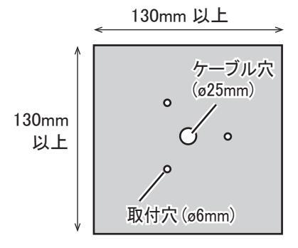
- 現地で取付台(130mm×130mm以上)を用意します。 錆びが発生する取付台の場合は、防錆剤を塗布してください。 注)取付け面は平らで、がたつきがない場所を選択してください。
- 取付穴 3ヵ所と、空中線ケーブル用の ケーブル穴(φ25±2mm)を1カ所あけま す(巻末の外寸図参照)。
注) 空中線部の船首マークが船首方向を向 くように、取付台に載せます。

3. 手順2のケーブル穴に空中線ケーブルのコネクタ部が上になるように取付 台の下から通します。
4. 空中線ケーブルのコネクタと空中線部を接続します。

注) 空中線部底面の銘板近くにある空気孔(4ヵ所)には接着剤を塗布しない でください。

-
5. コネクタ接続部に自己融着テープを2回巻き、その上からビニールテープ
- を1回巻きます。
- 注) このとき、空中線部とケーブルのコネクタ両方にテープがかかるように巻いてください。

- 空中線部の船首マークが船首方向に向くように調整します。 注)取付台に設置した空中線部が傾いていないことを確認してください。
-
空中線部の底面から4本のネジ(M5×20、平座金、バネ座金付)で手順2
の取付穴から空中線部を取付位置に固定します。ネジで固定後、ネジの頭に 工材の接着剤を塗布します。
- 注)ネジの長さは取付け位置の板厚によって異なります。
|
板厚
(取付け位置) |
M5 ネジの
長さ |
|
|---|---|---|
| 2 ~ 10mm |
20mm
(工材) |
|
|
M5 ネジ
(3 ヵ所、平座金 / |
上記以外 |
板厚 +
8 ~ 16mm (現地手配) |
| ★ 法 | - |
1.3 ポールマウント装備
あらかじめポールマウントキットと空中線部を組み立ててから、取付け位置に固定 します。

1.3.1 装備上の注意
- 取付け位置のポールの直径は 25 ~ 50mm 以内の必要があります。
- ポールマウントキットを取り付けた空中線部は船首マークが船首方向を向くよう に取り付けます。
- ホースクランプは取付け位置のポールの直径に応じて、正しいサイズのものを使用してください。
| 名称 | 適用マスト径 | 備考 |
|---|---|---|
| ホース | 20A ~ 25A ($\phi25 ~ 35mm) | 工材 CP20-04603 で標準支給 |
| クランプ | 32A ~ 40A ($$35 ~ 50mm) | オプション OP20-52 で支給 |
空中線部底面の銘板近くにある空気孔(4ヵ所)には接着剤を塗布しないでください。

1.3.2 必要な工具
本機を取り付ける前に、次の工具を事前に準備する必要があります。
| 名称 | 備考 |
|---|---|
| プラスドライバ | #2 |
| マイナスドライバ | ホースクランプ取付用 |
| レンチ | • ロックナット締付用(対辺 32mm) |
| • ポールマウント部材固定用(対辺 8mm) | |
| 束線バンド | 2本 (最低)、空中線ケーブルのポール固定用 |
| パテ | パイプのケーブルロ保護用 |
-
1.3.3 ポールマウントキットの組立て
- ロックナット(工材)をパイプ(工材)のネジ部の一番下まで取り付けます。
- 2. パイプのネジ部に接着剤を塗布し、ポールマウント部材を取り付けます。
- 3. 取り付けた組品を上下逆にして、レンチ(現地手配)を使ってロックナット をしっかりと固定します(締付トルク:15N•m)。

余分な接着剤を拭き取ります。 注)このとき、下図5か所の水抜き穴を塞がないように注意してください。

1章 取付け
-
1.3.4 取付け
-
ポールマウントキット組品にマスト取付金具のホースクランプを通し、組品のパイプの下から空中線ケーブルを通します。
- 注)アンカーが 上向き になるように取付補助金具を配置します。
-
ポールマウントキット組品にマスト取付金具のホースクランプを通し、組品のパイプの下から空中線ケーブルを通します。

2. 空中線ケーブルのコネクタと空中線部を接続します。その後、空中線部の底 面からポールマウントキットと空中線部を3本のネジ(M5、工材)で固定 します。

3. 空中線部組品にある取付補助金具のアン カーを、取付位置のポールの上部に載せま す。
4. ホースクランプのボルトを緩く締めます。

5. 空中線部の船首マークが船首方向を向くよ うに配置を調整します。

- 6. ホースクランプのボルトをしっかりと締め、空中線部組品を固定します。
- 7. 空中線ケーブルの余りの長さでループを作って、束線バンド(現地手配)で 取付位置のポールに固定します。

8. ケーブルを固定するために、パイプのケーブルロをパテ(現地手配)で保護 します。
1.4 ルーフマウント装備
オプションのルーフマウントキット(OP20-04602)を使うことで、空中線部を上か ら取り付けることができるため、ルーフトップへの装備が容易になります。
1.4.1 装備上の注意
- 曲面には装備しないでください。
- 取付け面とルーフマウントキットの境界、およびルーフマウントキットと空中線 部の境界に接着剤を塗布しないでください(1-10ページの手順9参照)。
- 空中線部底面にある銘板付近の空気孔(4ヵ所)を接着剤で塞がないでください。

1章 取付け
1.4.2 必要な工具
本機を取り付ける前に、次の工具を事前に準備する必要があります。
| 名称 | 備考 | |||
|---|---|---|---|---|
| 穴のこぎり | ケーブル穴用 (ф25mm) | |||
| やすり | ケーブル穴の切り口の処理用 | |||
| プラスドライバ | #2 | |||
-
1.4.3 取付け
- 現地で取付台(260mm 船尾方向×240mm 以上)を用意します。 錆びが発生する取付台の場合は、防錆剤を塗布してください。 注)取付け面は平らで、がたつきがない場所を選択してください。
-
取付け台の中央に空中線ケーブル用のケー ブル穴($25±2mm)を1カ所あけます (巻末の外寸図参照)。
- 注)ケーブル穴は右図を参照に適切な寸法で あけてください。穴が大きすぎると浸水 の恐れがあり、穴が小さすぎると、ケー ブルを配線しにくくなります。
- 260mm 以上 (-船尾方向-) ケーブル穴 (ø25±2mm) 240mm 以上 取付台 (上面から)
- 手順2のケーブル穴に空中線ケーブルのコ ネクタ部が上になるように取付台の下から 通します。

4. 空中線部とルーフマウントキットの船首マークが一致するように、ルーフマ ウントキットに空中線部を載せます。

5. 空中線部組品の上下を逆にして、ルーフマウントキットの底面から3本の ネジ(M5×20、工材)で空中線部と固定します。

-
アタッチメントパッキンを空中線ケーブルのコネクタに下まで押し込んで取り付けます。その後、アタッチメントパッキンの上面に接着剤(工材)を塗布し、空中線部ケーブルを空中線部に接続します。
- 注 1) アタッチメントパッキンを取り付けるとき、アタッチメントパッキンの 上下の向きに注意してください(次図参照)。
- 注 2) 空中線ケーブルを空中線部と接続するときに、アタッチメントパッキンの上面に必ず接着剤(工材、TB5211)を塗布してください。

ケーブル接続後、アタッチメントパッキンの下部に接着剤を塗布します。 注)ルーフマウントキット底面にある空気孔(12か所)を接着剤で塞がないようにしてください。
8. 空中線部上部にある船首マークが船首方向を向くように調整します(手順4 参照)。
-
9. 工材のネジ4本(M5×20)のネジ部に接着剤を塗布し、ルーフマウント キットを上から固定します(次図参照)。固定後は、ネジの頭にも接着剤を 塗布します。
- 注)取付け面とルーフマウントキットの境界、およびルーフマウントキットと 空中線部の境界に接着剤を塗布しないでください(下図の斜線部は塗布禁 止範囲)。

1.5 アンテナベース装備(オプション)
ポールマウントキットと直型アンテナベース(NO.13-QA330)(オプション)を使 うことで、次のような場所への装備が可能です。
- 斜面(傾き35°まで)
- 装備面が狭い場所
1.5.1 装備上の注意
- がたつきのある面には装備しないでください。
- 空中線部底面の銘板近くにある空気孔(4ヵ所)には接着剤を塗布しないでください。

1.5.2 必要な工具
本機を取り付ける前に、次の工具を事前に準備する必要があります。
| 名称 | 備考 |
|---|---|
| 電動ドリル | 取付穴用 |
| ドリルビット | φ4.2 ~ 5 |
| 穴のこぎり | ケーブル穴用 (¢25mm) |
| やすり | ケーブル穴の切り口の処理用 |
| プラスドライバ | #2 |
-
1.5.3 取付け
- 1.3.3節を参考にして、アンテナベースにポールマウントキットを組み立て ます。
注)ポールマウントキットに含まれるパイプは使用しません。
-
2. 空中線部の船首マークが船首方向を向くように直型アンテナベースを取付台 に配置します。斜面に取り付ける場合は、傾ける方向に注意して配置しま す。その後、取付け位置に4つの取付穴(∳4.2 ~ 5mm)をあけます。
- 注) アンテナベースは配置した向きによって傾けることができる方向が決まり ます。


- 3. 取付穴の中心に空中線ケーブル用のケーブ ル穴(φ25±2mm)をあけます。
- 取付け位置のケーブル穴の下から空中線 ケーブルを出して、直型アンテナベースの パイプを上方向に通します。


5. パイプを上方向に引っ張り、直型アンテナベースの底面とその内側(下図の 斜線部)に接着剤を塗布します。

1章 取付け
6 取付台にあけた取付穴と直型アンテナベース のネジ穴が一致するように配置します。この とき、船首方向を考慮し、直型アンテナベー スの向きを調整します。その後、4本のネジ (M5. 工材)を使ってしっかりと締めつけま す。

船首方向

-
7. 直型アンテナベースのセットビスを1つず つ外して、工材のセットビス(接着剤塗布 済み)と交換して取り付けます。締め付け 後、余分な接着剤はしっかりと拭き取りま す。
- 注) 接着剤が固まるには、およそ 30 分かかり ます。
- 8. 空中線ケーブルのコネクタと空中線部を接 続します。

直型アンテナベース

9. 空中線部の底面からネジ3本(工材、M5)を使って、空中線部を固定しま す。

10. 直型アンテナベースの六角ボルトを六角 レンチ(工材)で緩めて、船首マークが 船首方向を向くように空中線部の向きを 調整します。調整後、六角ボルトをしっ かりと締めつけます。

1.6 鳥除け(オプション)
オプションの鳥除け(OP20-54)を空中線部の 上部に取り付けることで、鳥が空中線部に止ま ることを軽減することができます。
2本の鳥除けにある両面テープを外して、空中 線部上部に取り付けます。取付後、空中線部と の接触面を覆うように接着剤を塗布します。

1.7 積雪カバー (オプション)
オプションの積雪カバーキット(OP20-53)を使用することで、空中線部での積雪 を軽減することができます。
取付け方については、キットに同梱されている要領書(C72-01901)を参照してください。
1.8 NMEA 2000 機器との接続
支給のケーブル組品を使って、本機のコネクタと NMEA 2000 ネットワークのバッ クボーン間を接続してください。(詳細は vi ページの「システム構成」参照)。
本機には NMEA 2000 に準拠する機器を接続します。以下の事項を考慮してください。
- 本機の LEN (Load Equivalency Number) は "4" です (LEN は、NMEA 2000 から 供給される電源において機器が消費する電流の単位で、NMEA 2000 ネットワー クも設計に重要)。
- 基本的にバックボーンケーブルに T 型コネクタを挿入し、引き込みケーブルを 介して機器を接続します。
- バックボーンケーブルの両端には終端器を取り付けます。
- NMEA 2000 のネットワーク電源はバックボーンの中央に入れます(電圧降下の 関係)。
NMEA 2000 (CAN) bus とは?
単一配線で、複数の情報や信号を通信できるプロトコルです(NMEA 2000 に準拠)。すべての情報/信号には ID があり、センサーの認識とエラー検出が可能です。 さらに、同一ネットワーク内への機器追加が簡単に行えるため、拡張性が格段に向 上します。
サービスマンの方へ: NMEA 2000 (CAN) bus の詳細については「Furuno CAN bus Network Design Guide (TIE-00170)」を参照してください。
結線の防水処理
ケーブルコネクタや、CAN bus (NMEA 2000) ネットワークのTコネクタに水がか かる恐れがある場合は、下記のようにコネクタ部を防水処理してください。
- 1) コネクタ部にビニールテープを1回巻きます。
- 2) ビニールテープの上に、自己融着テープを1回巻きます。
- 3) 自己融着テープの上に、ビニールテープを2回巻きます。

2章 装備後の設定
本機は、電源投入のたびにコールドスタートし、約60秒で方位計算が終了します。 30分経過しても船首方位が計算されない場合は、空中線部の取付位置が適当でない 可能性があります。本機と衛星の間の通信を遮断するような障害物がないことを確 認してください。造船所内または岸壁で確認するときは、周囲に影になるような障 害物や建造物がないか確認してください。
方位誤差が 5° 以上あるときは、船首方位を確認しながら空中線部の向きを合わせます。
本機は NMEA 2000 ネットワークを介して、次のいずれかの方法で設定を行うこと ができます。船首方位が計算されたあと、装備後の設定を行ってください。
-
次のいずれかの機種から本機の設定メニューを開き、設定を行う
- TZTL12F/TZTL15F/TZT2BB (ソフトウェア Ver. が "06.01" 以降)
- NAVpilot-300 (ソフトウェア Ver. (操作部)が"01.07"以降) (ソフトウェア Ver. (制御部)が"01.06"以降)
- TZT12F/TZT16F/TZT19F
接続機器から本機の設定メニューを開く方法については、各機種の取扱説明書または装備要領書を参照してください。
● PCを接続し、SC設定ツールから設定を行う
SC 設定ツールの操作や設定項目については、当社支店・営業所・代理店にお問い合わせ下さい。
- 注1)本機を再起動した場合は、設定メニューを開くために再接続の操作が必要で す。
- 注 2) 本書では、TZTL15F から設定メニューを開いた場合の設定項目を記載してい ます。設定メニューの構成については、巻末の「メニューツリー」を参照し てください。
2.1 [GNSS Setup] メニュー
[GNSS Setup] メニューでは、使用禁止衛星の設定や仰角マスクの設定などを行うことができます。
| メニュー項目 | 内容 |
|---|---|
| [Disable SV] | |
| [QZSS All] | [YES] に設定すると、準天頂衛星システム(QZSS)の全衛星を使用禁止にします。 |
| メニュー項目 | 内容 |
|---|---|
| [QZSS] → | 衛星番号を指定して、準天頂衛星システム(QZSS)の使用禁止衛星を設定で |
| [QZSS1] | きます。使用禁止衛星は、3つまで設定可能です。使用禁止衛星を設定しない |
| [QZSS] → | 場合は、「0」に設定してください。 |
| [QZSS2] | 注) [QZSS All] を [YES] に設定した場合は、設定値が自動的に「0」に変わり |
| [QZSS] → | ます。 |
| [GPS All] | [YES]に設定すると、GPS 衛星システムの全衛星を使用禁止にします。 |
| [GPS] → [GPS1] | 衛星番号を指定して、GPS 衛星システムの使用禁止衛星を設定できます。使用 |
| [GPS] → [GPS2] | 禁止衛星は、3つまで設定可能です。使用禁止衛星を設定しない場合は、「0」 |
| [GPS] → [GPS3] | に設定してください。 |
| 注)[GPS All] を [YES] に設定した場合は、設定値が自動的に「0」に変わりま | |
| ग ् | |
| [GLONASS All] | [YES] に設定すると、GLONASS 衛星システムの全衛星を使用禁止にします。 |
| [GLONASS] → | 衛星番号を指定して、GLONASS 衛星システムの使用禁止衛星を設定できま |
| [GLONASS1] | す。使用禁止衛星は、3つまで設定可能です。使用禁止衛星を設定しない場合 |
| [GLONASS] → | は、「0」に設定してください。 |
| [GLONASS2] | 注) [GLONASS All] を [YES] に設定した場合は、設定値が自動的に「0」に変 |
| [GLONASS] → | わります。 |
| [GLONASS3] | |
| [Galileo All] | [YES] に設定すると、Galileo 衛星システムの全衛星を使用禁止にします。 |
| [Galileo] → | 衛星番号を指定して、Galileo 衛星システムの使用禁止衛星を設定できます。 |
| [Galileo1] | 使用禁止衛星は、3つまで設定可能です。使用禁止衛星を設定しない場合は、 |
| [Galileo] → | 「0」に設定してください。 |
| [Galileo2] | 注) [Galileo All] を [YES] に設定した場合は、設定値が自動的に「0」に変わり |
| [Galileo] → | ます。 |
| 加たショウト(加た地理)の料はナナキレナナーティズ記庁した加たいてはナス | |
| [SV ELEV] |
| 仰角マスク (仰角制限) の 叙 個を 入力します。 ここで 設定した 仰角以下にめる
| 海見は 測位に 使用しませ / 一 仰色 マスクを 直く 認定する と 測位 特度 け向 ト |
|
||単生は、側位に使用しません。||| 用マハクを同て設定すると、側位相度は向上
|| ますが | 真く設定|| すぎスと衛星数が小たくたスため |||| 位ができたくたス |
|
| ことがあります。 | |
| [SBAS] | |
| [SBAS Mode] | SBAS 測位を使用する場合は [On] を選択します。 |
| [SBAS Search] | SBAS 測位する衛星を自動で設定する場合は [Auto]、手動で設定する場合は |
| [Manual]を選択します。 | |
| [SBAS Satellite | SBAS 測位する衛星を設定します。 |
| Selection] | 注) このメニューは [SBAS Search] の設定は [Manual] の場合のみ有効 |
| [Disable SBAS] | |
| [Disable SBAS] → [SBAS]] | |
| [Disable SRAS] -> | |
| [SBAS2] | SBAS 測位を無効にする衛星を最大3つまで設定します。 |
| [Disable SBAS] → | |
| [SBAS3] |
2.2 [Sensor] メニュー
[Sensor] メニューでは、本機の装備位置、自船船体情報、補正値の設定などを行い ます。
| メニュー項目 | 内容 | |||
|---|---|---|---|---|
| [Offset] | ||||
| [HDG] | 船首方位の補正値を設定します。船首方位が右舷方向にずれている場合はマイナスの値、左舷方向にずれている場合はプラスの値を設定します。 | |||
| [Pitch] | ピッチ(縦揺れ)の補正値(°)を設定します。 | |||
| [Roll] | ロール(横揺れ)の補正値(°)を設定します。 | |||
| [SOG/3-Axis Speed] | 3軸船速の補正値(%)を入力します。 | |||
| [Air Pressure] | 気圧の補正値(hPa)を設定します。 | |||
| [Air Temperature] | 気温の補正値(°C)を設定します。 | |||
| [Smoothing] | ||||
| [SOG/COG] |
対地船速 / 対地針路データをスムージング(平均化)する時間(秒)
を設定します。 |
|||
| [3-Axis Speed] |
3軸船速データをスムージング(平均化)する時間(秒)を設定しま
す。 |
|||
| [ROT] |
回頭角速度データをスムージング(平均化)する時間(秒)を設定し
ます。 |
|||
| [DR Time] | ||||
| [DR Time] |
衛星信号が途絶えたあと、推測航法(Dead-reckoning)状態で方位出力
を維持する時間を設定します。設定された時間以内に衛星信号を受信 できない場合、本機は方位出力を停止します。 |
|||
| [Ship Size, ANT/CALC-SPI | D Position] | |||
| 3軸船速表示の精度向上の | つため 、各船に応じた数値を入力してください。本機の装備位置や3軸 | |||
| 船速計測用の基準点などに | は、下図のとおりです。 | |||
| 基準点(0.0) 一 | ||||
|
Z (
船体高さ 基準点(0.0) |
(+) ★ X (-) ★ X (+) ★ K ( | |||
| [Ship's Width] | 自船の船体幅(最も幅の広い部分の船体幅)を入力します(設定範囲:1.0~999.9m)。 | |||
| [Ship's Length] |
自船の船体長(船の中心を通る船首から船尾までの船の長さ)を入力
します(設定範囲:1.0~999.9m)。 |
|||
| メニュー項目 | 内容 | ||
|---|---|---|---|
| [Ship's Height] | 自船の船体高さ(キールの下部からマストの上部までの船の高さ)を | ||
| 設定します(設定範囲:1.0~199.9m)。 | |||
| [ANT Position X0] | 本機の右舷 / 左舷方向の装備位置(本機の中心)を設定します。装備 | ||
| 位置が右舷側の場合は正、左舷側の場合は負の値を入力します(設定 | |||
| 範囲:-327.64 ~ +327.64m)。 | |||
| [ANT Position Y0] | 本機の船首 / 船尾方向の装備位置を設定します。船首を0とし、船首 | ||
| から船尾方向への距離で設定します(設定範囲:0.0~999.9m)。 | |||
| [ANT Position Z0] | サテライトコンパス.の高さ方向の装備位置を設定します。船底を0 | ||
| とし、船底からの距離で設定します(設定範囲:0.0~199.9m)。 | |||
| [CALC-SPD-POSN Y1 | 3 軸船速の船速出力位置を設定します(船首尾方向)。3 軸船速では、 | ||
| (BOW)] | 本機の装備位置とは別に、前後2ヵ所で船速を計算します。基準点か | ||
| [CALC-SPD-POSN Y2 | ら、船速を測定したい位置までの距離(船尾方向) | ||
| (Stern)] | を入力してください(Y1:船首付近、Y2:船尾付近)。 | ||
| 注) 工場出荷時、、Y1 および Y2 はそれぞれ下記のように設定されて | |||
| います。 | |||
| • Y1:0m(船首位置) | |||
| • Y2:10m(船首から10m後方の位置) | |||
| [CALC-SPD-POSN Z | 3 軸船速の船速出力位置を設定します(高さ方向)。たとえば吃水線で | ||
| (Height)] | の船速を測定したい場合は、船底から吃水線までの高さを入力します。 | ||
2.3 [Input/Output] メニュー
[Input/Output] メニューでは、本機から出力される PGN のオン / オフや送信周期を設定します。
送信周期の設定が可能な PGN は、次表のとおりです。設定可能な送信周期の値は、 PGN ごとに異なります。PGN ごとの設定範囲は、AP-1 ページの「メニューツリー」 を参照してください。出力を停止する場合は、「Off」に設定してください。
注)通常は、初期設定のまま使用してください。送信周期を変更する場合は、変更 が必要な PGN のみ調整してください。短い送信周期の PGN 出力が多いと、 設定した送信周期で出力できなくなる可能性があります。
| PGN | PGN 名 | PGN | PGN 名 |
|---|---|---|---|
| 065280 | Heave | 129540 | GNSS Sats in View |
| 126992 | System Time | 130310 | Environmental Parameters |
| 126993 | Heartbeat | 130312 | Temperature |
| 127250 | Vessel Heading | 130314 | Actual Pressure |
| 127251 | Rate of Turn | 130316 | Temperature, Extended Range |
| 127252 | Heave | 130577 | Direction Data |
| 127257 | Attitude | 130578 | Vessel Speed Components |
| 127258 | Magnetic Variation | 130842 | Six Degrees of Freedom Movement |
| 129025 | Position, Rapid Update | 130843 | Heel Angle and Roll Information |
| 129026 | COG and SOG, Rapid Update | 130845 | Multi Sats In View Extended |
| 129029 | GNSS Position Data | 130846 | Motion Sensor Status |
| 129539 | GNSS DOPs | 1 | Extended |
2.4 [System] メニュー
[System] メニューでは、本機のシステム情報の表示、セルフテストの実行、工場出 荷時設定へのリセットなどを行うことができます。
| メニュー項目 | 内容 |
|---|---|
| [System Information] | |
| [Main PCB] | MAIN 基板のバージョンを表示します。 |
| [Starter Version] | Starter のバージョンを表示します。 |
| [Booter 1 Version] | Booter 1 のバージョンを表示します。 |
| [Booter 2 Version] | Booter 2 のバージョンを表示します。 |
| [Application Version] | ソフトウェアバージョンを表示します。 |
| [Serial No.] | 本機のシリアル番号を表示します。 |
| [GNSS 1] | GNSS コア1~4のバージョンを表示します。 |
| [GNSS 2] | |
| [GNSS 3] | |
| [GNSS 4] | |
| [CAN Unique Number] | CAN 固有 ID を表示します。 |
| [CAN Address] | 本機に割り当てられ CAN アドレスを表示します。 |
| [Powered Time] | 本機の電源を最後に入れてからの経過時間を表示します。 |
| [Overall Powered Time] | MAIN 基板の累計稼働時間を表示します。 |
| メニュー項目 | 内容 | ||||
|---|---|---|---|---|---|
| [Simple Diagnostic Test] | |||||
| [ROM] | ROM のテスト結果を表示します (OK/NG)。 | ||||
| [RAM] | RAM のテスト結果を表示します (OK/NG)。 | ||||
| [Rate Gyro Status] | 角速度センサーのテスト結果を表示します (Good/Bad)。 | ||||
| [Accelerometer Status] | 加速度センサーのテスト結果を表示します (Good/Bad)。 | ||||
| [Magnetic Sensor Status] | 磁気センサーのテスト結果を表示します (Good/Bad)。 | ||||
| [Press./Temp. Sensor | 気圧センサー / 温度センサーのテスト結果を表示します | ||||
| Status] | (Good/Bad)。 | ||||
| [Installation Status] | 本機を装備した場所での異常な振動の回数を表示します。 | ||||
| [GNSS 1 Status] | GNSS1~4のテスト結果を表示します(Good/Bad)。 | ||||
| [GNSS 2 Status] | |||||
| [GNSS 3 Status] | |||||
| [GNSS 4 Status] | |||||
| [Antenna 1 Status] | アンテナ1~4のテスト結果を表示します (Good/Bad)。 | ||||
| [Antenna 2 Status] | |||||
| [Antenna 3 Status] | |||||
| [Antenna 4 Status] | |||||
| [Advanced Diagnostic Test] | |||||
| [ROM] | それぞれの項目についてのテスト結果を表示します(OK/ | ||||
| [RAM] | NG)。 | ||||
| [Rate Gyro Test] | 注) このテストは自動的に行われ、テストしている間は | ||||
| [Accelerometer Test] | データは出力されません。 | ||||
| [GNSS 1 RAM Test] | |||||
| [GNSS 1 ROM Test] | 4 | ||||
| [GNSS 2 RAM Test] | |||||
| [GNSS 2 ROM Test] | |||||
| [GNSS 3 RAM Test] | |||||
| [GNSS 3 ROM Test] | |||||
| [GNSS 4 RAM Test] | |||||
| [GNSS 4 ROM Test] | |||||
| [Reset Setting] | |||||
| [Menu Settings] | [YES]を選択すると、全てのメ 注)日時情報も工場出 | ||||
| |ニュー設定が工場出荷時の設定に | 荷時設定に戻りま | |||||
| | 戻ります。 すので、衛星情報 | |||||
| | 美行後、平機を中起期 うる必安/ // 「が取得できるまで」 | |||||
| [Factory Reset] |
のりより。
IVESIを選択すると一全てのメーロンは測位が行われま |
||||
|
|[1L5] を選びするこ、エミック
| ーュー設定が工場出荷時の設定に せん。 |
|||||
| 戻ります。 | |||||
| [Restart] | |||||
| [System Restart] | [YES]に設定すると、本機が再起動します。 | ||||
| 注) 再起動中は、本機からのすべてのデータ出力が停止し | |||||
| ます。係留中など安全な場合にのみ実施してくださ | |||||
| ι | |||||
3章 保守
3.1 保守点検
機器の性能を十分に発揮させるには、定期的な点検が必要です。定期的に次の項目を点検してください。
| 項目 | チェックポイント | 対処 |
|---|---|---|
| コネクタ | コネクタすべてが確実に | ケーブルのコネクタを確実に接続する。 |
| 締まっているか確認す | ||
| る。 | ||
| ケーブル配線 | ケーブルに傷などがない | ケーブル交換が必要な場合は、お買い上 |
| か確認する。 | げ先、または当社支店・営業所に問い合 | |
| わせる。 | ||
| ユニット | カバーの清掃 | ほこりや汚れは、柔らかい乾いた布でふ |
| カバー | き取る。泥や塩などがこびり付いている場 | |
| 合は、濡れた布でゆっくりとふきます。 | ||
| 清掃にシンナーやアセトン、アルコール、 | ||
| ベンジンなどのプラスチック溶剤は使用 | ||
| しないでください。 | ||
| 表面の塗装や表示部の文字などが溶ける | ||
| 場合があります。 |
3.2 トラブルシューティング
「故障かな」と思ったら、まず次の点検を行ってください。修理は資格をもった サービスマンに依頼してください。また、サービスマンを呼ぶときには、点検した 事柄を詳しく報告していただくと、サービスが迅速になります。
| 項目 | 考えられる要因 | 対処 |
|---|---|---|
| データが出力 | ケーブルの接続不良 | ケーブルコネクタがしっかりと接続されてい |
| されない。 | / 損傷 / 欠陥 | ることを確認する。またケーブルに損傷がな |
| いか確認する。NMEA 2000 バスに電力が供給 | ||
| され、正しく動作していることを確認する。 | ||
| 必要に応じて、お買い上げ先、または当社支 | ||
| 店・営業所に問い合わせる。 | ||
| 表示部の設定不備 | 接続されている NMEA 2000 機器側の説明書を | |
| (NMEA 2000 機器) | 参照して、メニュー設定を確認する。 | |
| データが正し | 装備後の設定でオフ | • 装備場所が適切か確認する。 |
| く出力されな | セットが正しく設定 | • 接続されている他の機器での設定値を確認 |
| と | されていない / 適用 | する。必要に応じて、オフセットを再調整 |
| されていない | する。 | |
| 位置情報が取 | アンテナ4に | アンテナ4では GLONASS 衛星の使用はでき |
| 得できない | GLONASS 衛星が設 | ません。GLONASS 衛星を使用する場合は、ア |
| 定されている | ンテナ1~3を選択してください。 |
追補1 メニューツリー
本書では、TZTL12F/TZTL15F/TZT2BB、およびNAVpilot-300から設定メニューを開いた場合の メニューツリーを記載しています。SC設定ツールのメニューツリーについては、SC設定ツー ルの取扱説明書(OMJ-72851)を参照してください(詳細は当社支店・営業所・代理店にお問 い合わせ下さい)。

ด 前ページからの続き – Input/Output – PGN* – ---------------------------------------126992 (Off, 1000 , 2000) [ - 126993 (Off. 60000 ) *: PGN設定では測定 単位としてミリ秒(ms) - 127250 (Off, 20, 25, 50, 100 , 200, 1000, 2000) [ -127251 (Off. 20. 25. 50. 100 . 200. 1000. 2000) を使用します。 - 127252 (Off, 20, 25, 50, 100 , 200, 1000, 2000) - 127257 (Off, 20, 25, 50, 100 , 200, 1000, 2000) [ -127258 (Off. 1000 , 2000) [ -129025 (Off. 100 , 200, 1000, 2000) -129026 (Off, 200, 250 , 1000, 2000) -129029 (Off. 1000 , 2000) [ -129539 (Off. 1000 , 2000) — 129540 (Off, 1000 , 2000) [ - 130310 (Off. 500 , 1000, 2000) -130312 (Off. 500, 1000 ) -130314 (Off, 1000, 2000 ) [ -130316 (Off, 1000, 2000 ) [ -130577 (Off. 20, 25, 50, 100, 200, 1000 , 2000) -130578 (Off, 200, 250 , 1000, 2000) - 130842 (Off. 20, 25, 50, 100 , 200) -130843 (Off. 20, 25, 50, 100 , 200) -130845 (Off. 1000 ) - 130846 (Off. 1000 ) [ — Main PCB (Display only) 「 System -Information - Starter Version (Display only) - Booter1 Version (Display only) -Booter2 Version (Display only) - Application Version (Display only) - Serial No. (Display only) — GNSS 1 (Display only) [ — GNSS 2 (Display only) [ - GNSS 3 (Display only) - GNSS 4 (Display only) [ - CAN Unique Number (Display only) - CAN Address (Display only) - Powered Time (Display only) - Overall Powered Time (Display only) 次ページに続く
2 前ページからの続き
   - Simple -----
                  -ROM (OK, NG)
    Diagnostic
                  — RAM (OK, NG) [
    Test
                   - Rate Gvro Status (Good, Bad)
                  - Accelerometer Status (Good, Bad)
                   - Magnetic Sensor Status (Good, Bad)
                   - Press./Temp. Sensor Status (Good, Bad)
                   - Installation Status (0 to 99) [
                    - GNSS 1 Status (Good, Bad)
                   - GNSS 2 Status (Good, Bad) [
                  - GNSS 3 Status (Good, Bad) [
                   - GNSS 4 Status (Good, Bad)
                      ntenna 1 Status (Good, Bad) [
                     Antenna 2 Status (Good, Bad)
                    - Antenna 3 Status (Good, Bad)
                   - Antenna 4 Status (Good, Bad) [
                 ROM (OK, NG) 「
    Advanced —
                   - RAM (OK, NG) [
    Test
                  — Rate Gyro Test (OK, NG) [
                  — Accelerometer Test (OK, NG) [
                   - GNSS 1 RAM Test (OK, NG) [
                   - GNSS 1 ROM Test (OK, NG) [
                   - GNSS 2 RAM Test (OK, NG) [
                  - GNSS 2 ROM Test (OK, NG) [
                  - GNSS 3 RAM Test (OK, NG) [
                   - GNSS 3 ROM Test (OK, NG) [
                   - GNSS 4 RAM Test (OK_NG) [
                   - GNSS 4 ROM Test (OK, NG)
                   - Menu Settings (YES, NO)
                Factory Reset (YES, NO)
    Setting
   - Restart
           --------------------------------------
追補 2 測地系リスト
| 001. | WGS84 | 001. | Reheman (avel San Salvadar la ) | ||
|---|---|---|---|---|---|
| 001. | WGS72 | 091. | NORTH AMERICAN 1927 |
Bahamas (excl. San Salvador Is.)
Bahamas San Salvador Is |
|
| 002 | TOKYO | : Mean Value (Japan, Korea & Okinawa) | 092. | NORTH AMERICAN 1927 (Cont'd): | Canada (ind Newfoundland Is) |
| 004: | NORTH AMERICAN 1927 | : Mean Value (CONUS) | 094: | NORTH AMERICAN 1927 (Cont'd): | Alberta & British Columbia |
| 005: | EUROPEAN 1950 | : Mean Value | 095: | NORTH AMERICAN 1927 (Cont'd): | East Canada |
| 006: | AUSTRALIAN GEODETIC 1984 | : Australia & Tasmania | 096: | NORTH AMERICAN 1927 (Cont'd): | Manitoba & Ontario |
| 007: | ADINDAN | : Mean Value (Ethiopia & Sudan) | 097: | NORTH AMERICAN 1927 (Cont'd): | Northwest Territories & Saskatchewan |
| 008: | ADINDAN | : Ethiopia | 098: | NORTH AMERICAN 1927 (Cont'd): | Yukon |
| 009: | ADINDAN | : Mali | 099: | NORTH AMERICAN 1927 (Cont'd): | Canal Zone |
| 010: | ADINDAN | : Senegal | 100: | NORTH AMERICAN 1927 (Cont'd): | Caribbean |
| 011: | ADINDAN | Sudan | 101: | NORTH AMERICAN 1927 (Cont'd): | Central America |
| 012: | AFG | : Somalia | 102: | NORTH AMERICAN 1927 (Cont'd): | Cuba |
| 013: | AIN EL ABD 1970 | 103: | NORTH AMERICAN 1927 (Cont'd): | Greenland | |
| 014: | ANNA 1 ASTRO 1965 |
. Cocos Is.
: Mean Value |
104: | NORTH AMERICAN 1927 (Cont'd): | Mexico |
| 015: | ARC 1950 | : Rotewana | 105: | NORTH AMERICAN 1983 | Alaska |
| 010. | ARC 1950 | : Lesotho | 100: | NORTH AMERICAN 1983 | |
| 017. |
ARC 1950
ARC 1950 |
· Malawi | 107: |
CONUS
Maxiaa Control Amorica |
|
| 010. | ARC 1950 | Swaziland | 100. | ||
| 020 | ARC 1950 | : Zaire | 110. | OLD EGYPTIAN 1930 | Equat |
| 021: | ARC 1950 | : Zambia | 111: | OLD HAWAIIAN | Mean Value |
| 022: | ARC 1950 | : Zimbabwe | 112: | OLD HAWAIIAN | Hawaii |
| 023: | ARC 1960 | : Mean Value (Kenya & Tanzania) | 113: | OLD HAWAIIAN : | Kauai |
| 024: | ARC 1960 | : Kenya | 114: | OLD HAWAIIAN : | Maui |
| 025: | ARC 1960 | : Tanzania | 115: | OLD HAWAIIAN : | Oahu |
| 026: | ASCENSION IS. 1958 | : Ascension Is. | 116: | OMAN : | Oman |
| 027: | ASTRO BEACON "E" | : Iwo Jima Is. | 117: | ORDNANCE SURVEY OF GREAT BRITA | AN 1936: Mean Value |
| 028: | ASTRO B4 SOR. ATOLL | : Iern Is. | 118: | ORDNANCE SURVEY OF GREAT BRITA | AIN 1936: England |
| 029: | ASTRO POS /1/4 | St. Helena Is. | 119: | ORDNANCE SURVEY OF GREAT BRITA | AIN 1936: England, Isle |
| 030: | ASTRONOMIC STATION 1952 | . Marcus IS. | 400 | of Man & Wales | |
| 031: | · Efate & Erromando Is | 120: | ORDNANCE SURVEY OF GREAT BRITA | AIN 1936: Scotland & | |
| 032: | BELLEVUE (IGN) |
: Elate & Elfondingo IS.
: Bermuda le |
404. | Shetland IS. | |
| 033. | · Columbia | 121: | |||
| 034. | Argentina | 122. | Diteairn le | ||
| 036. | CANTON IS 1966 | · Phoenix Is | 123. |
Filiaitti IS.
1963: South Chile (near 53°S) |
|
| 037 | CAPE | : South Africa | 124. | PROVISIONAL SOUTH AMERICAN | 1956: Mean Value |
| 038 | : Mean Value (Florida & Bahama Is.) | 126 | PROVISIONAL SOUTH AMERICAN | 1956 Bolivia | |
| 039: | CARTHAGE | : Tunisia | 127: | PROVISIONAL SOUTH AMERICAN | 1956: Chile-Northern Chile |
| 040: | CHATHAM 1971 | : Chatham Is. (New Zealand) | (near 19°S) | ||
| 041: | CHUA ASTRO | : Paraguay | 128 | PROVISIONAL SOUTH AMERICA | N 1956 Chile-Southern Chile |
| 042: | CORREGO ALEGRE | : Brazil | (near 43°S) | ||
| 043: | DJAKARTA (BATAVIA) | : Sumatra Is. (Indonesia) | 120. | ||
| 044: | DOS 1968 | : Gizo Is. (New Georgia Is.) | 129. | 1956: Equador | |
| 045: | EASTER IS. 1967 | : Easter Is. | 130. |
1950. Ecuadol
1956: Guyana |
|
| 046: | EUROPEAN 1950 (Cont'd) | : vvestern Europe | 132 | PROVISIONAL SOUTH AMERICAN | 1950: Ouyana |
| 047: | EUROPEAN 1950 (Cont'd) | . Cyprus | 133 | PROVISIONAL SOUTH AMERICAN | 1956 . Venezuela |
| 048: | : England Sectland Channel & Shotland Is | 134: | PUERTO RICO | Puerto Rico & Virgin Is. | |
| 049. | EUROPEAN 1950 (Cont d) |
|
135: | QATAR NATIONAL | Qatar |
| 050. | EUROPEAN 1950 (Cont'd) | · Greece | 136: | QORNOQ : | South Greenland |
| 051. | EUROPEAN 1950 (Cont'd) | : Iran | 137: | ROME 1940 : | Sardinia Is. |
| 053 | EUROPEAN 1950 (Cont'd) | : Italy. Sardinia | 138: | SANTA BRAZ : | Sao Miguel, Santa Maria Is. (Azores) |
| 054: | EUROPEAN 1950 (Cont'd) | : Italy, Sicily | 139: | SANTO (DOS) : | Espirito Santo Is. |
| 055: | EUROPEAN 1950 (Cont'd) | : Norway & Finland | 140: | SAPPER HILL 1943 : | East Falkland Is. |
| 056: | EUROPEAN 1950 (Cont'd) | : Portugal & Spain | 141: | SOUTH AMERICAN 1969 : | Mean Value |
| 057: | EUROPEAN 1979 | : Mean Value | 142: | SOUTH AMERICAN 1969 | Argentina |
| 058: | GANDAJIKA BASE | : Republic of Maldives | 143: | SOUTH AMERICAN 1969 | Bolivia |
| 059: | GEODETIC DATUM 1949 | : New Zealand | 144: | SOUTH AMERICAN 1969 | Brazii |
| 060: | GUAM 1963 | : Guam Is. | 145. | Columbia | |
| 061: | GUX 1 ASTRO | 140. | Equador | ||
| 062: | HJORSEY 1955 | 148 | SOUTH AMERICAN 1969 | Guyana | |
| 063: | HUNG KUNG 1963 | · Thailand & Vietnam | 149: | SOUTH AMERICAN 1969 | Paraguay |
| 065 | · Bangladesh India & Nepal | 150: | SOUTH AMERICAN 1969 | Peru | |
| 065. | · Ireland | 151: | SOUTH AMERICAN 1969 : | Trinidad & Tobago | |
| 067 | ISTS 073 ASTRO 1969 | : Diego Garcia | 152: | SOUTH AMERICAN 1969 : | Venezuela |
| 068 | JOHNSTON IS 1961 | : Johnston Is. | 153: | SOUTH ASIA : | Singapore |
| 069 | KANDAWALA | : Sri Lanka | 154: | SOUTHEAST BASE : | Porto Santo & Madeira Is. |
| 070: | KERGUELEN IS. | : Kerguelen Is. | 155: | SOUTHWEST BASE : | Faial, Graciosa, Pico, Sao Jorge & Terceria Is |
| 071: | KERTAU 1948 | : West Malaysia & Singapore | 156: | TIMBALAI 1948 : | Brunei & East Malaysia (Sarawak & Sabah) |
| 072: | LA REUNION | : Mascarene Is. | 157: | TOKYO : | Japan |
| 073: | L. C. 5 ASTRO | : Cayman Brac Is. | 158: | Korea | |
| 074: | LIBERIA 1964 | : Liberia | 159: |
Okinawa
Triatan da Cunha |
|
| 075: | LUZON | : Philippines (excl. Mindanao Is.) | 160. | ||
| 076: | : IVIIIIIIIIIIIIIIIIIIIIIIIIIIIIIIIIIII | 162 | WAKE-ENIWETOK 1960 | Marshall Is | |
| 077: | MARE 19/1 |
. Mane IS.
: Salvage Islands |
162. | ZANDERIJ | Surinam |
| 078: | MARCUASTRO | 164 | BUKIT RIMPAH | Bangka & Belitung Is (Indonesia) | |
| 0/9: | 165 | CAMP AREA ASTRO | Camp Momurdo Area. Antarctica | ||
| 000: | · Midway Is | 166: | G. SEGARA | Kalimantan Is. (Indonesia) | |
| 001: | : Nigeria | 167: | HERAT NORTH | Afghanistan | |
| 083- | NAHRWAN | : Masirah Is. (Oman) | 168: | HU-TZU-SHAN | Taiwan |
| 084 | NAHRWAN | : United Arab Emirates | 169: | TANANARIVE OBSERVATORY 1925 : | Madagascar |
| 085 | NAHRWAN | : Saudi Arabia | 170: | YACARE : | Uruguay |
| 086 | NAMIBIA | : Namibia | 171: | RT-90 : | Sweden |
| 087: | MAPARIMA, BWI | : Trinidad & Tobago | 172: | CK42 (PULKOVO 1942) : | Russia |
| 088: | NORTH AMERICAN 1927 | : Western United States | 173: | FINNISH KKJ : | Finland |
| 089: | NORTH AMERICAN 1927 | : Eastern United States | 174: | PZ90 : | Russia |
| 000. | NORTH AMERICAN 1927 | : Alaska | 1/5: | CEAD | Russia |
追補3 SBAS のサービス範囲
静止衛星を使用した GPS の広域補強システムを総称して SBAS (Satellite Based Augmentation System) といいます。静止衛星から広範囲に GPS の誤差補正情報などが放送されるため、GPS 測位に比べ高精度に測位できます。
米国、欧州、日本、インドでは、広域補強システムを運用しており、相互に共通運用性があり ます。各プロバイダ(WAAS、EGNOS、MSAS、GAGAN)のサービス範囲については、下図 を参照してください。本書では、WAAS、EGNOS、MSAS、GAGAN を含めて、「SBAS」と記 載しています。

SBAS の衛星配置
| プロバイダ | 運用国 | 衛星の種類 | 経度 | 衛星番号 |
|---|---|---|---|---|
| 米国 | Intelsat Galaxy XV | 133°W | 135 | |
| WAAS | TeleSat Anik F1R | 107.3°W | 138 | |
| Inmarsat-4-F3 | 98°W | 133 | ||
| 欧州 | Inmarsat-3-F2/AOR-E | 15.5°W | 120 | |
| ECNOS | Artemis | 21.5°E | 124 | |
| EGNOS | Inmarsat-4-F2 | 25°E | 126 | |
| SES-5 | 5°E | 136 | ||
| MSAS | 日本 | MTSAT-1R | 140°E | 129 |
| WISAS | MTSAT-2 | 145°E | 137 | |
| CACAN | GSAT-8 | 55°E | 127 | |
| UAUAN | イント | GSAT-10 | 83°E | 128 |
2014/3/6 現在
FURUNO
サテライトコンパス SCX-20 仕 様
1. 総合
| 1575.42 MHZ (GPS/Gallieo/QZSS/SBAS), 1602.5625 MHZ (GLUNASS) | ||
|---|---|---|
| (2) | 受信コード | C/A コード (GPS/QZSS/SBAS) 、E1B(Galileo)、L10F (GLONASS) |
| (3) | 姿勢角精度 | ヘディング/ロール/ピッチ |
| 1.0°rms(静止時)、0.5°rms(動揺時) | ||
| (4) | 追従角速度 | 45° /s |
| (5) | ヒーブ精度 | 5 cm (1 σ) |
| (6) | 姿勢角静定時間 | 約 60 秒 |
| (7) | 測位精度(電離層、マル | チパスの状態により変化) |
| GNSS | 約5m(2drms、HDOP<4) | |
| MSAS | 約4m(2drms、HDOP<4) | |
| WAAS | 約3m(2drms、HDOP<4) | |
| (8) | 初期捕捉時間 | 約 50 秒 |
| (9) | 更新周期 | 姿勢角:最大 50 Hz、位置:最大 10 Hz |
| (10) | 船速精度 | |
| SOG | 0.02 kn (衛星 5 個以上) | |
| 0.2 kn(衛星 3~4 個) | ||
| VBW (対地船速) | 0.02 kn (衛星 5 個以上、空中線位置) | |
| 0.08 kn(衛星5個以上、空中線位置以外) | ||
| 船速の 2.0%または 0.02 kn のいずれか大きい方(衛星 3~4 個) | ||
| (11) | 環境センサー | |
| 気圧 | 測定範囲:850~1100 hPa(周囲温度 0~+50℃) | |
| 精度 : ±1.0 hPa(オフセット調整後) | ||
| 気温 | 測定範囲:−20℃~+55℃(相対風速 4kn 以上) | |
| 精度 : ±2.0℃(オフセット調整後) | ||
2. インターフェイス
| (1) | ポート数 | NMEA2000 : 1 | 1ポート | ||||
|---|---|---|---|---|---|---|---|
| (2) | 入出力 PGN | ||||||
| 入力 | 059392/904, | 060160/416/928, | 061184, 0 | 65240, 12 | 6208/720, | 130847 | |
| 出力 | 059392/904, | 060928, 061184, | 065280, | 126208/46 | 64/720/992 | 2/993, | |
| 126996/998, | 127250/251/252/ | /257/258, | |||||
| 129025/026 | /029/538/539/540. | 130310/3 | 312/314/31 | 16/577/578 | 3. |
3. 電源
DC12-24 V (10.8-31.2V) : 0.2-0.1 A (LEN:4、9 V 時)
130816/817/818/819/822/823/833/834/842/843/845/846/847
4. 環境条件
| (1) | 使用温度範囲 | -25℃~+55℃(保存温度:-30℃~+70℃) |
|---|---|---|
| (2) | 相対湿度 | 95%以下 (+40°C) |
| (3) | 保護等級 | IP56 |
| (4) | 振動 | IEC60945 Ed. 4 |
5. ユニットカラー
N9.5
| A-2 |
9401 –0
1/1 |
急人贏港
EMARKS |
C7286-M01-A | ||||||||
|---|---|---|---|---|---|---|---|---|---|---|---|
| CODE NO. 001-556-150-00 20BK-X-1 TYPE CP20-04601 20BK-X-1 |
型名/規格 数量 用減
DESCRIPTIONS 0'TY RI MSX20 SUS304 3 |
CODE 000-160-442-10 |
AWING FOR REFERENCE ONLY.)
:Lectric co . Ltd. |
||||||||
|
工事材料表
INSTALLATION MATERIALS |
華号 名 秋 閣 図 MNE 0011LINE 1477 '475 ' |
(感図のナ法は、参考者です。 DIMENSIONS IN DR
FURUNO E |
|||||||||
| G LIST 208K-X-9851 -3 1/1 |
250
FUEVWO 000-036-766-00 1 |
001 000 100 00 1 0P20-04602 1 001-556-170-00 (*1) |
CP20-04603 1
(*2) |
CP20-04605 1
(*3) 001-556-240-00 (*3) |
2
10
0MC-72860-* 1
0MC-72860-* 1 |
ATION.
PECIFICATION. |
IONS IN DRAWING FOR REFERENCE ONLY.)
C7286-Z01-D |
||||
| PACKINC | SCX-20-* | - SATELLITE COMPASS | 1-7'LL (3'E'2) NMEA |
工事材料
INSTALLATION MATERIALS |
ルーフマウントキット
ROOF MOUNT KIT |
本 - ルマウントキット
POLE MOUNT KIT |
77.4取付金具
MAST MOUNTING KIT |
國書
DOCUMENT
取扱説明書(和/类) OPERATOR'S MANUAL (JP/EN) |
|
(略図の寸法は、参考値です。 DIMENSI |
A-2
| ∢ | |||||||
|---|---|---|---|---|---|---|---|
| CODE NO. | 001-556-200-00 | 20BK-X-9403 -0 | |||||
| 1 | IYPE | CP20-04603 | 1/1 | ||||
| 事材料表 | |||||||
| 2 | ALLATION MATERIALS | ||||||
|
名 称
NAME |
略 図OUTLINE |
日
DESC |
名/規格
RIPTIONS |
数量
0' TY |
用途/備考
REMARKS |
||
| #° –ルマウント | EIO * | CP20-0460 | 4 | - | |||
| PULE MUUNI ASSEMBLT |
CODE
NO. |
001-556-210-00 | - | ||||
|
□y}tyk
Loov wirt |
32 | 20-040-1 | 18-0 | - | |||
| 2 I L |
CODE
NO. |
100-429-750-10 | |||||
| 提業剤袋詰 | |||||||
| ADHESIVE |
164
135 128 |
TB5211 50
CODE |
90 | - | |||
| ON | 001-477-870-00 |
| ODE NO. | 001-556-170-00 | 20BK-X-9402 -1 | |||||
|---|---|---|---|---|---|---|---|
| F | TYPE | CP20-04602 | 1/1 | ||||
| Н | 事材料表 | ||||||
| INST | ALLATION MATERIALS | ||||||
|
ц
В В |
名
NAME |
略 図
OUTLINE |
型
BES |
名/規格
CRIPTI ONS |
数量
0'TY |
用途/備考
REMARKS |
|
| - |
7997422610° 942
ΑΤΤ ΑΡΗΜΕΝΤ GASKET |
$36 | 20-040-1 | 106-0 | - | ||
|
CODE
NO. |
100-429-670-10 | ||||||
| 2 |
ルーフマウント音い村
POOGE MOLINIT TEVILIDE |
20-040-1 | 107–2 | - | |||
| 256 |
CODE
NO. |
100-429-682-10 | |||||
| ŝ | レーフマウントハ*ッキン | ¢22¢ | 20-040-1 | 108-1 | - | ||
| KOOF MOUNI GASKEI | ф48 |
CODE
NO. |
100-429-691-10 | - | |||
| 4 | +トラスタッピンネジ 1シュ | 5X25 SUS | 304 | ||||
| - | SELF-TAPPING SCREW |
CODE
NO. |
000-162-610-10 | 4 | |||
| ц | 接着剤袋詰 | 164 | TR6911 F | 50 | |||
| 2 | ADHESIVE | 128 | CODE NO. | 001-477-870-00 | _ | ||
| ų | フラッシュマウント形 紙 | 210 | C79_0180 | 4-t | |||
| > |
FLUSH MOUNTING
TEMPLATE |
297 | CODE 0120 | 000-195-297-1* | - | ||
| ٢ | ルーフマウントキット注意 | 210 | C79-0190 | л-* | |||
| - |
NOTICE FOR
INSTALLATION |
297 | CODE NO. | 000-197-436-1* | - |
IMENSIONS IN DRAWING FOR REFERENCE ONLY.) FURUNO ELECTRIC CO . , LTD. 図の寸法は、参考値です。 |
DIMENSIONS IN DRAWING FOR REFERENCE ONLY.) FURUNO ELECTRIC CO .. LTD. 考値です。 、世版
C7286-M02-B
C7286-M03-A
| ODE NO. | 001-556-240-00 | 20BK-X-9404 -0 | ||||
|---|---|---|---|---|---|---|
| 'YPE | CP20-04605 | 1/1 | ||||
| Н | [事材料表 | |||||
| INST | FALLATION MATERIALS | |||||
|
影
影 |
名
NAME 茶 |
略 図
OUTLINE |
型
DES |
名/規格
CRIPTIONS |
数量
0'TY |
用途/備考
REMARKS |
| - |
n° 47°
PIPE |
137 1
137 1 1025 |
20-007-3 | 011-4 | - | |
| - |
CODE
NO. |
100-183-264-10 | ||||
| 2 | 取付補助金具 | 17 10 | 20-040-1 | 117–2 | - | |
| FIAING SUFFURI FIAIURE | 126 |
CODE
NO. |
100-429-742-10 | |||
| ŝ |
ΥΥΥ
Σττ 1 Ιανο |
150 × | CV-150B | - | ||
|
CODE
NO. |
000-167-183-10 | |||||
| ~ | 赤ースクランプ 。 (ABA) | 112 A | Slisate 1 | 2MM 38-50 | ||
| ŧ | HOSE CLAMP |
CODE
NO. |
000-196-736-10 | 7 |
各図の寸法は、参考値です。 DIMENSIONS IN DRAWING FOR REFERENCE ONLY.) FURUNO ELECTRIC CO .. LTD.
C7286-M04-A
ĥ


D-2
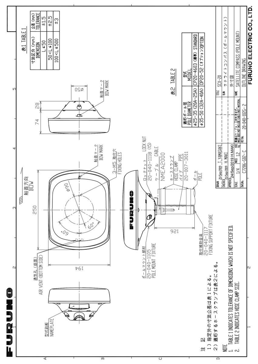
D-3
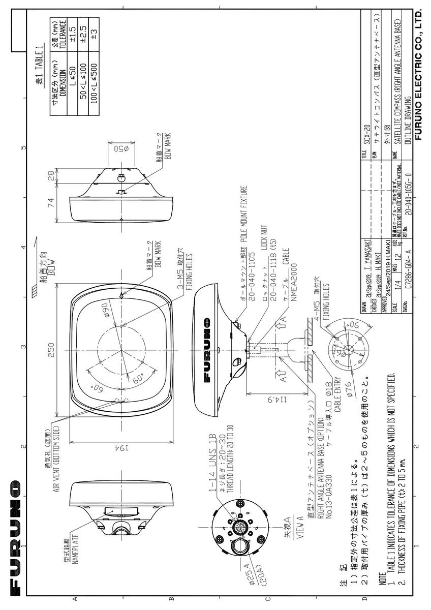


 Loading...