

Page 1

T
HD SA
TELLITE COMPASS
SC-
50
Page 2

Thepaperusedinthismanual
9-52 Ashihara-cho,9-52 Ashihara-cho,
A
A
*
0
*
0
*
0
*
0
*
O
*
O
*
O
*
O
Nishinomiya 662-8580, JAPANNishinomiya 662-8580, JAPAN
Telephone :Telephone : 0798-65-21110798-65-2111
FaxFax 0798-65-42000798-65-4200
::
iselementalchlorinefree.
Your Local Agent/Dealer Your Local Agent/Dealer
ll rights reserved.
ll rights reserved.
Pub. No.Pub. No. OME-72510OME-72510
(( DAMIDAMI ))
SC-50SC-50
Printed in JapanPrinted in Japan
FIRST EDITION :FIRST EDITION : FEB.FEB. 20042004
CC :: JUN.JUN. 15, 200515, 2005
0014854802*
0014854802*
0014854802*
0014854802*
* 0 0 0 1 4 8 5 4 8 0 2 ** 0 0 0 1 4 8 5 4 8 0 2 *
ME72510C00*
ME72510C00*
ME72510C00*
ME72510C00*
* O M E 7 2 5 1 0 C 0 0 ** O M E 7 2 5 1 0 C 0 0 *
Page 3
SAFETY INSTRUCTIONS
Safety Instructions for the Operator Safety Instructions for the Installer
WARNINGWARNING
ELECTRICAL SHOCK HAZARD
Do not open the equipment.
Only qualified personnel
should work inside the
equipment.
Do not disassemble or modify the
equipment.
Fire, electrical shock or serious injury can
result.
Immediately turn off the power at the
switchboard if the equipment is emitting
smoke or fire.
Continued use can cause fatal damage to
the equipment. Contact a FURUNO agent
for service.
Do not place liquid-filled containers on
the top of the processor unit.
Fire or electrical shock may result if the
liquid enters the equipment.
Use the proper fuse.
Use of a wrong fuse can damage the
equipment and cause fire.
CAUTIONCAUTION
No one navigation device should ever
be solely replied upon for the navigation
of a vessel.
Always confirm position against all available aids to navigation (incl. nautical charts),
for safety of vessel and crew.
WARNINGWARNING
Turn off the power at the switchboard
before beginning the installation.
Fire or electrical shock can result if the
power is left on.
Do not install the equipment where it
may get wet from rain or water splash.
Water in the equipment can cause fire,
electrical shock or damage to the equipment.
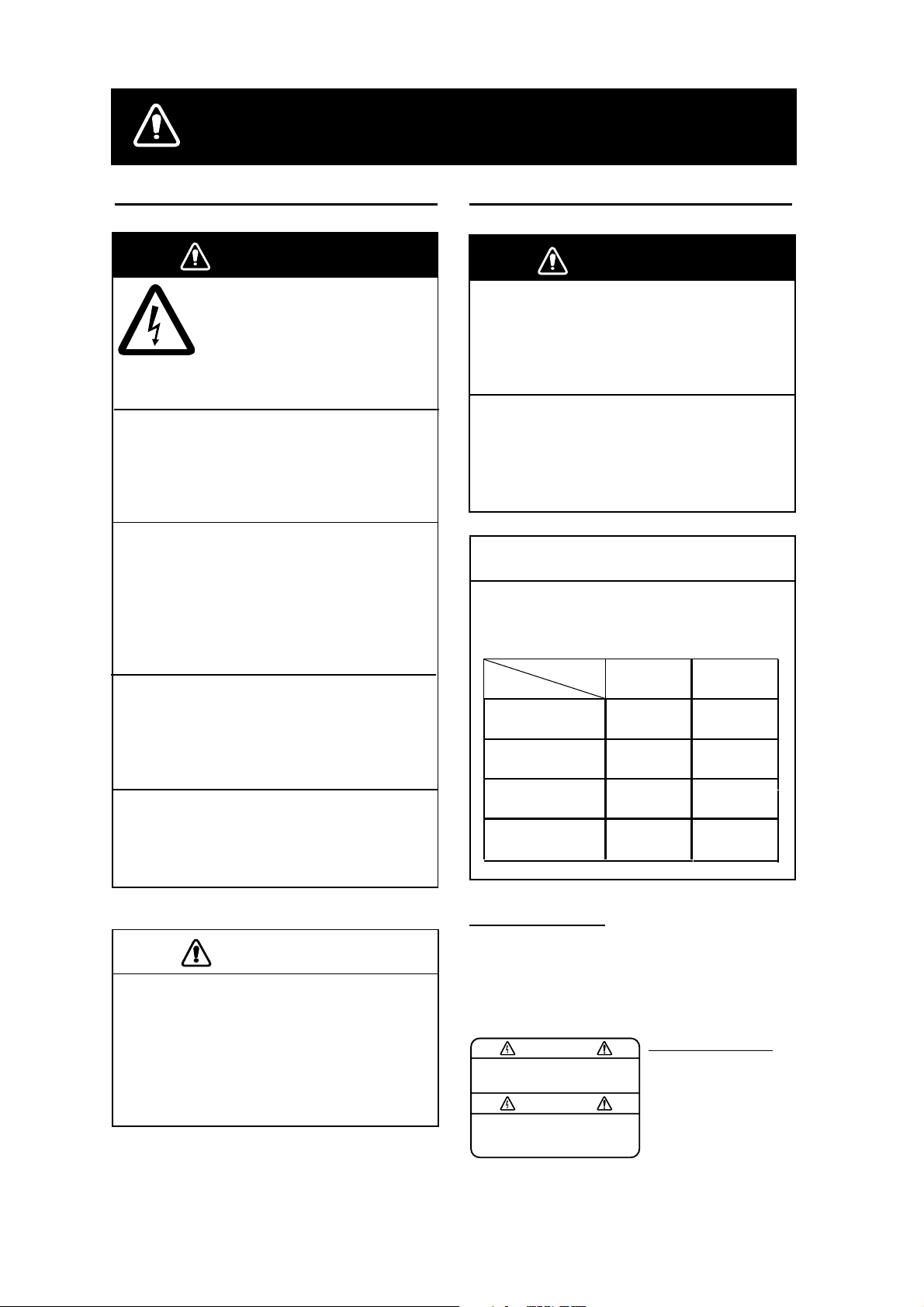
NOTICENOTICE
Observe the following compass safe
distances to prevent interference to a
magnetic compass:
Standard
Compass
Display unit
SC-502
Processor unit
SC-501
Antenna unit
SC-303
Antenna unit
SC-603
WARNING LABEL
A warning label is attached to the
processor unit. Do not remove the label.
If the label is missing or damaged,
contact a FURUNO agent or dealer
about replacement.
WARNING
To avoid electrical shock, do not
remove cover. No user-serviceable
parts inside.
0.4 m 0.3 m
0.9 m
0.3 m 0.3 m
0.3 m 0.3 m
WARNING LABEL
Name: Warning Label (1)
Type: 86-003-1011-1
Code No.: 100-236-231
Steering
Compass
0.6 m
i
Page 4

TABLE OF CONTENTS
FOREWORD ..................................................................................................................iv
SYSTEM CONFIGURATION...........................................................................................v
EQUIPMENT LIST..........................................................................................................vi
SPECIFICATIONS.....................................................................................................SP-1
INSTALLATION...................................................................................................... 1-1
1
1.1 Mounting Considerations..................................................................................................... 1-1
1.1.1 Antenna unit............................................................................................................. 1-1
1.1.2 Display unit, processor unit...................................................................................... 1-3
1.2 Installing the Antenna Unit................................................................................................... 1-4
1.2.1 Antenna unit SC-303 ............................................................................................... 1-4
1.2.2 Antenna unit SC-603 ............................................................................................... 1-7
1.3 Installing the Processor Unit.............................................................................................. 1-12
1.3.1 Bulkhead mount..................................................................................................... 1-12
1.3.2 Deck mount ............................................................................................................ 1-13
1.3.3 Installation on the underside of a desk .................................................................. 1-14
1.4 Installing the Display Unit .................................................................................................. 1-15
1.4.1 Desktop, overhead mounting................................................................................. 1-15
1.4.2 Flush mount ........................................................................................................... 1-15
1.5 Wiring................................................................................................................................. 1-17
1.6 Initial Settings .................................................................................................................... 1-20
1.6.1 Confirming satellite status...................................................................................... 1-20
1.6.2 Choosing mounting method................................................................................... 1-21
1.7 Connection of External Equipment.................................................................................... 1-22
1.7.1 General wiring........................................................................................................ 1-22
1.7.2 Fabrication of cables.............................................................................................. 1-23
2 OPERATION........................................................................................................... 2-1
2.1 Controls................................................................................................................................ 2-1
2.2 Turning the Power On/Off.................................................................................................... 2-2
2.3 Panel Illumination, Display Contrast.................................................................................... 2-2
2.4 Choosing a Display..............................................................................................................2-3
2.4.1 Description of displays............................................................................................. 2-3
2.5 Alarm Setup ......................................................................................................................... 2-6
2.6 Confirming Satellite Status .................................................................................................. 2-7
2.7 GPS Setup........................................................................................................................... 2-8
2.7.1 Displaying the GPS setup menu.............................................................................. 2-8
2.7.2 GPS SETUP menu description................................................................................ 2-8
2.8 Output Data.......................................................................................................................... 2-9
2.8.1 Heading.................................................................................................................... 2-9
2.8.2 Log pulse ............................................................................................................... 2-13
2.9 System Setup ....................................................................................................................2-14
2.9.1 Geodetic data......................................................................................................... 2-14
2.9.2 Units of measurement............................................................................................ 2-15
2.9.3 Using local time...................................................................................................... 2-15
ii
Page 5

2.9.4 Time format............................................................................................................ 2-15
2.9.5 Demonstration mode.............................................................................................. 2-16
2.10 WAAS/DGPS Setup........................................................................................................... 2-17
2.11 OTHERS Menu.................................................................................................................. 2-20
2.12 TRIP Menu......................................................................................................................... 2-21
2.13 Resetting Distance Run..................................................................................................... 2-22
2.14 Choosing External Heading Source for Backup................................................................ 2-22
3 MAINTENANCE, TROUBLESHOOTING................................................................3-1
3.1 Preventive Maintenance ...................................................................................................... 3-1
3.2 Troubleshooting ................................................................................................................... 3-2
3.3 Diagnostics .......................................................................................................................... 3-3
3.4 Program Number ................................................................................................................. 3-7
3.5 Clearing Data....................................................................................................................... 3-7
3.6 Replacement of Battery ....................................................................................................... 3-8
3.7 Replacement of Fuse........................................................................................................... 3-9
3.8 Error Messages ................................................................................................................... 3-9
APPENDIX................................................................................................................AP-1
1. Menu Tree.............................................................................................................................. AP-1
2. Digital Interface...................................................................................................................... AP-2
3. Input/Output Ports ................................................................................................................. AP-8
4. Parts List and Parts Location .............................................................................................. AP-10
5. Geodetic Chart Codes ......................................................................................................... AP-12
6. Principle of Satellite Compass............................................................................................. AP-13
7. What is WAAS? ................................................................................................................... AP-14
PACKING LIST
OUTLINE DRAWINGS
INTERCONNECTION DIAGRAM
INDEX.........................................................................................................................IN-1
Declaration of Conformity
iii
Page 6

v
FOREWORD
A Word to the Owner of the SC-50
FURUNO Electric Company thanks you for purchasing the FURUNO SC-50
THD Satellite Compass. (Hereafter, for sake of brevity, we refer to the SC-50 as
Satellite Compass.) We are confident you will discover why the FURUNO name
has become synonymous with quality and reliability.
For over 50 years FURUNO Electric Company has enjoyed an enviable
reputation for quality and reliability throughout the world. This dedication to
excellence is furthered by our extensive global network of agents and dealers.
Your satellite compass is designed and constructed to meet the rigorous
demands of the marine environment. However, no machine can perform its
intended function unless properly installed and maintained. Please carefully read
and follow the operation, installation and maintenance procedures set forth in
this manual.
We would appreciate feedback from you, the end-user, about whether we are
achieving our purposes.
Thank you for considering and purchasing FURUNO.
Features
The SC-50 is a new satellite compass designed with FURUNO’s advanced GPS
kinematic technology. This compass finds a wide range of applications for any
type of ships and mobile units at sea or on land.
The main features are
• Perfect for use as heading sensor for Radar/ARPA, AIS, ECDIS, scanning
sonar
• There are no mechanical parts such as gimbals or rotating motor, thus the
compass is free from routine maintenance
• The performance is not affected by geomagnetism thus it is suitable for use on
any vessel
• No need for speed correction like a gyrocompass
• Short settling time - three minutes
• Meets the following requirements: IMO MSC. 116(73), ISO/FDIS 22090-3,
IMO A. 694(17), IEC 60945 (2002-08), IEC 61162 (2000).
i
Page 7
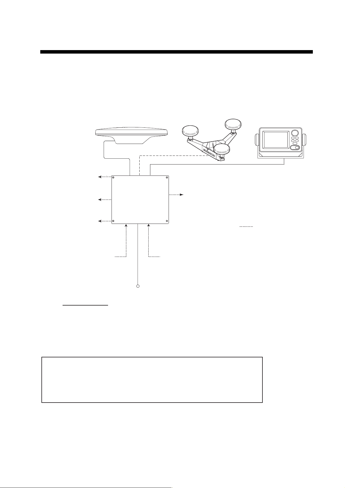
SYSTEM CONFIGURATION
The SC-50 consists of an antenna, a display unit and a processor unit. The
tri-antenna system accommodates three antennas/receiver units and is available
in a low-profile radome type or open type. The tri-antenna system helps reduce
the influence of ship's motion (rolling).
Analog pitch
Analog roll
Log/Heading alarm
(Contact)
External heading data
Antenna Unit
SC-303
Processor Unit
SC-501
Antenna Unit
SC-603
OR
3
6 ports for Heading or Navigation Data
(5 AD-10/IEC 61162 ports, 1 AD-10 port)
External DPGS
Beacon Receiver
Display Unit
SC-502
2
: Option
12-24 VDC
Category of Units
Processor Unit:Protected from weather
Display Unit: Protected from weather
Antenna Unit: Exposed to weather
System configuration
This GPS receiver complies with Canadian standard RSS-210 (Low Power
License-Exempt Radio communication Devices).
Operation is subject to the following two conditions:
(1) this device may not cause interference, and
(2) this device must accept any interference, including interference that may
cause undesired operation of the device.
v
Page 8

EQUIPMENT LIST
Standard supply
Name Type Code No. Qty Remarks
GPS Antenna
Display Unit SC-502 1
Processor Unit SC-501 1
Installation
Materials
SC-303 Radome type
SC-603
CP20-02230* 004-378-110 TPPX cable
CP20-02260* 004-379-660
CP20-02231* 004-378-050 1 For SC-303
CP20-02600 000-041-905 1
CP20-02203* 004-380-660 1
Choose one
1
Open type
TNC cable
For processor unit:
CP20-02601*,
MJ-A7SPF0006-100
For display unit:
Tapping screw (5X20 4
pcs.)
CP20-02201* 004-377-570 1
CP20-02202* 004-377-590 1 For SC-603
Spare Parts SP20-01101* 004-379-720 1 For processor unit
Antenna base for SC-603
Optional supply
Name Type Code No. Qty Remarks
Antenna
Cable Set
Cable Assy. TPPX6-3D2V-15M 000-143-559 1 Antenna cable
Flush Mount F OP20-29* 000-041-405 1 For display unit
Flush Mount S OP20-17* 000-040-720 1 For display unit
Bird-repellent
fixture
* See packing list at back of manual.
CP20-01700 004-372-110 30 m
CP20-01710 004-372-120
OP20-35 004-380-820 1 For SC-303, 9 pcs.
OP20-36 004-380-830 1 For SC-603, 4 pcs.
OP20-37 004-380-840 1 For SC-603, 1 pc.
1
50 m
3 sets
required
vi
Page 9

THD SPECIFICATIONS OF THD SATELLITE COMPASS
SC-50
1 GENERAL
1.1 Heading Accuracy ±1.0° (95%)
1.2 Heading Resolution 0.1°
1.3 Follow-up 45°/s rate-of-turn
1.4 Settling Time 3 minutes
1.5 Position Accuracy 10 m, or 5 m (DGPS), 95% of the time
1.6 Heading/Nav Data Output
AD-10 format: 1 port (specialty port)
AD-10 format 5 ports or IEC 61162 format 10 ports
(selectable on menu)
IEC 61162 format is RS-485 level
Sentence: HDT, HDM, ROT, ATT, VDR, VTG, GGA, GNS
GLL, VHW, VBW, HVE, ZDA
1.7 Log Signal Output 1 port, log pulse (pulse signal)
1.8 Heading Alarm Output 1 port, alarm output (contact signal)
1.9 Motion Output Signal 1 port pitch, 1 port roll
1.10 External Heading Input 1 port AD-10 or IEC61162 format (auto recognition)
‐AD-10: backup heading
‐IEC 61162: water tracking speed input (sentence: HDT, HDG,
HDM, VBW, VHW, VLW)
1.11 External Beacon Input 1 port, RTCM SC-104 format (RS-232 level)
2 DISPLAY UNIT
2.1
Display Type 4.5 inch monochrome LCD, 120 x 64 dots
2.2 Effective Area 60 mm (H) x 95 mm (W)
2.3 Contrast 64 levels
2.4 Display Mode Heading, Nav data, Steering, Compass rose, Rate of turn and
Speed modes
3 POWER SUPPLY
12-24 VDC: 1.2-0.5 A
4 ENVIRONMENTAL CONDITIONS AND EMC
4.1 Ambient Temperature
Display/Processor Unit -15°C to +55°C, Designed for protected area
Antenna Unit -25°C to +70°C, Designed for exposed area
4.2 Humidity 93% ±3% at 40°C
SP - 1 E7251S01B
Page 10

4.3 Waterproofing
Antenna Unit IPX6
Display Unit IPX5
Processor Unit IPX0
4.4 Vibration IEC 60945
5 COATING COLOR
5.1 Display/Processor Unit Panel: N3.0 Newtone No.5 (dark gray)
Chassis: 2.5GY5/1.5 (light gray)
5.2 Antenna Unit N9.5 (white)
SP - 2 E7251S01B
Page 11
1 INSTALLATION
1.1 Mounting Considerations
1.1.1 Antenna unit
General
•
Keep the length of the antenna cable in mind when selecting a mounting
location.
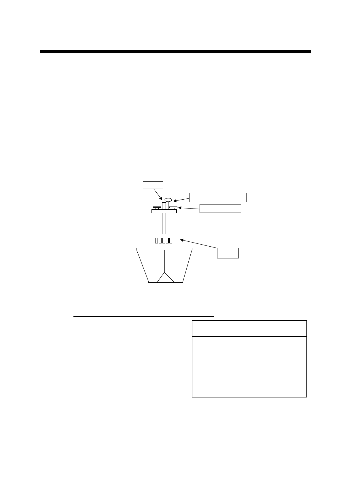
Installing the antenna above superstructures
•
The antenna must be mounted above all other structures on the vessel to
obtain an unobstructed view of the satellites regardless of vessel heading.
Failure to do so will cause shadows and multipath reflection problems.
Mast
SC-series Antenna
Radar Antenna
Exam ple of antenna installed above all s uper s tructures
Installing the antenna below superstructures
If it is not possible to mount the
antenna above all superstructures on
the vessel, as shown in the illustration
above, shading and multipath
problems may occur on at least one
heading, and possibly more. To
possibly avoid those problems,
observe the guidelines in this section.
If the antenna is installed below any
superstructure, the installation must
be done over a two-day period, following
the procedure in the service manual.
At least 12 hours are required to capture
tracking data to measure multipath indexes
and locate areas of shading.
Bridge
NOTICE
1-1
Page 12

1. INSTALLATION
•
The horizontal separation between the antenna and masts must be as follows:
Mast diameter Separation distance (minimum)
10 cm 1.5 m
30 cm 3 m
SC-50’s
antenna
Horizontal
separation
distance
Mast, etc.
Mast, etc.
Less than 10
TOP VIEW
°
Horizontal separation between ant enna and masts
•
The field of view above the antenna should be as shown below, ±80° against
zenith. To avoid reflections from masts and the like, locate the antenna well
away from the shadows of the radar mast, etc.
Zenith
-80°+80
SIDE VIEW
°
SC-series antenna
Antenna and field of view
•
Locate the antenna unit above the radar antenna, out of the radar beam.
1-2
SC-series Antenna
Radar Antenna
Page 13
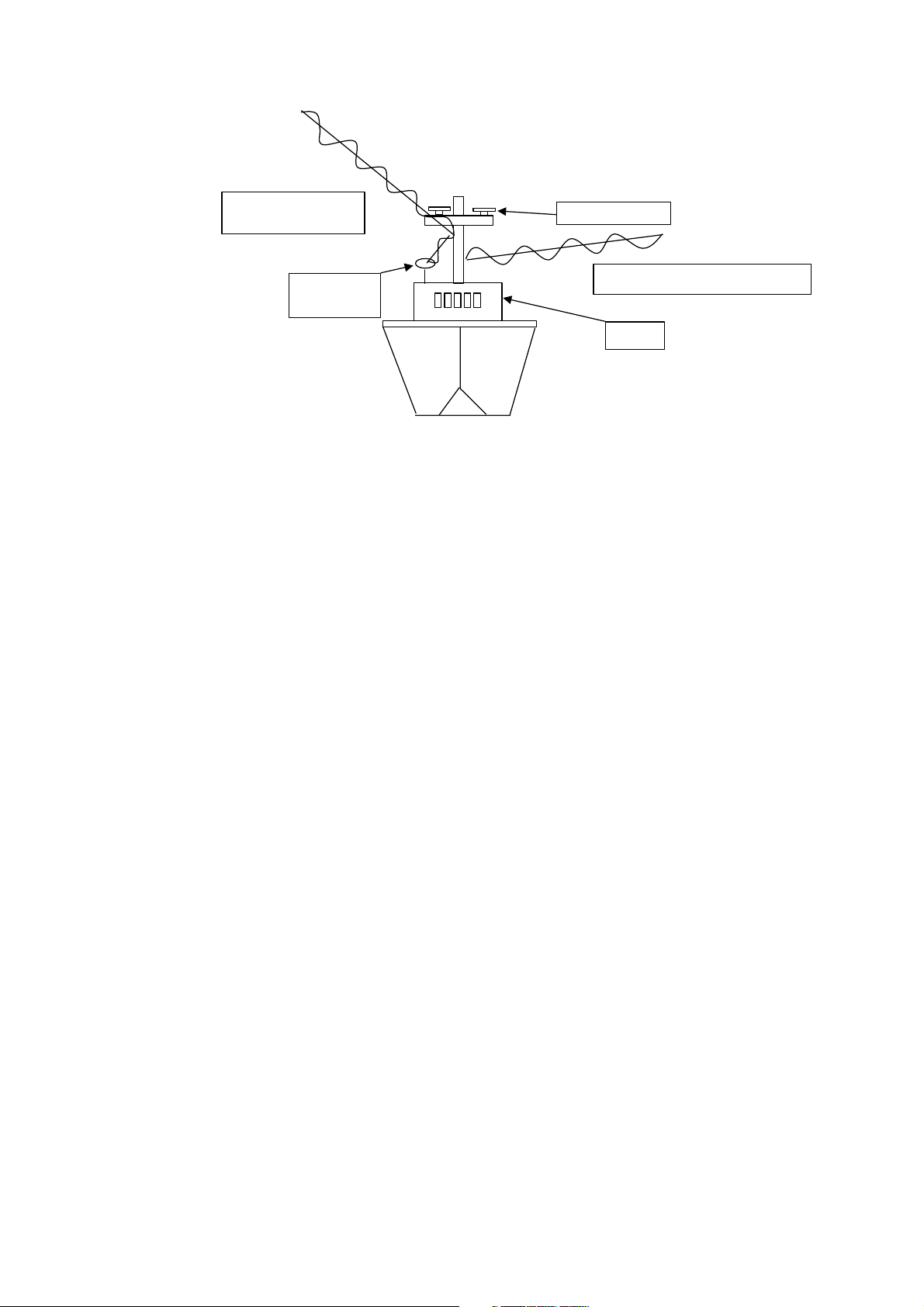
1. INSTALLATION
Location influenced
by reflected wave.
SC-series
Antenna
Exam ple of antenna inst alled below superstructures
1.1.2 Displa y uni t, pr oc es sor un it
•
Choose a location where vibration and shock are minimal.
•
Install the units well away from locations subject to rain and water splash.
•
Locate the units away from air conditioner vents.
•
Keep the units out of direct sunlight because of heat that can build up inside
their cabinets.
Radar Antenna
Reception blocked by mast.
Bridge
•
Choose a well-ventilated location.
•
For the display unit, choose a location where it can be easily operated.
•
Leave sufficient space around the units to permit access for maintenance. See
the outline drawing for recommended maintenance space.
1-3
Page 14
1. INSTALLATION
1.2 Installing the Antenna Unit
1.2.1 Antenna unit SC-303
Note: “Bird-repellent fixtures” (supplied) may be attached to the antenna cover to
prevent birds from alighting on the cover. If it is more convenient to attach
them before fixing the antenna unit to the mounting location, do step 9
before fixing the antenna unit.
NOTICE
Fasten the antenna to the mounting
location lastly if it is more convenient
to connect the antenna cable before
mounting the antenna unit.
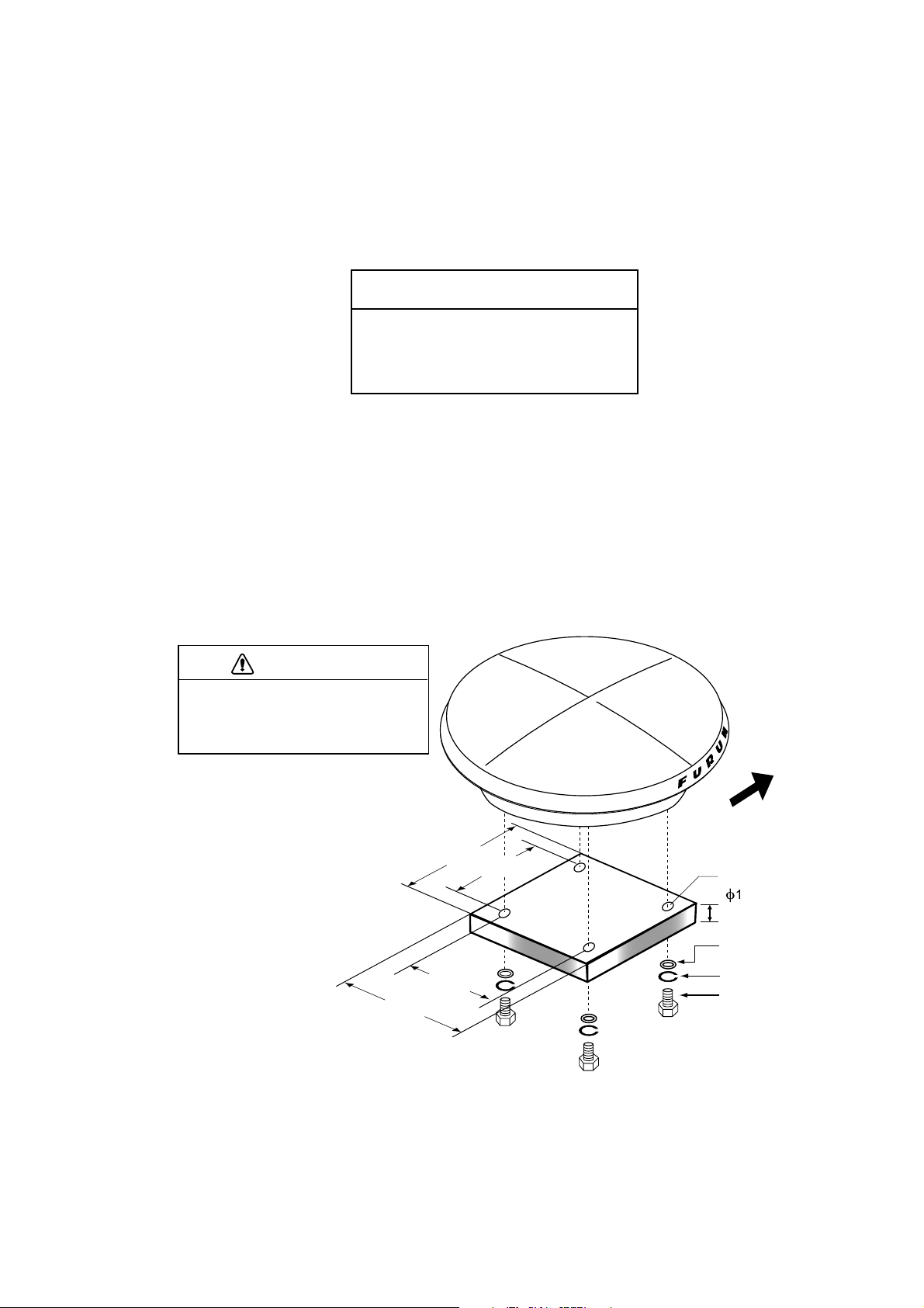
1. Prepare a mounting platform (wood, steel or aluminum) in accordance with
the illustration shown below. If corrosive material is used, take necessary
anti-corrosion measures.
Note: When drilling holes in the platform, be sure they are parallel with the
fore-and-aft line.
2. Orient the unit so the two lines on the base is facing the bow and then fasten
the antenna unit to the platform with four sets of M10 hex. bolts, spring
washers and flat washers. (The installation error should be within ±2.5°.) The
torque for the hex. bolts should be between ±20 2Nm.
NOTICE
Do not open the antenna.
This installation does not require removal
of the antenna cover.
240
240
160
F
160
U
R
U
N
BOW
Fixing Hole
(
f
11 mm)
5-10 mm
Flat Washer
Spring Washer
Hex. Bolt
1-4
Mounti ng dimensions for antenna, orient ing the antenna
Page 15
1. INSTALLATION
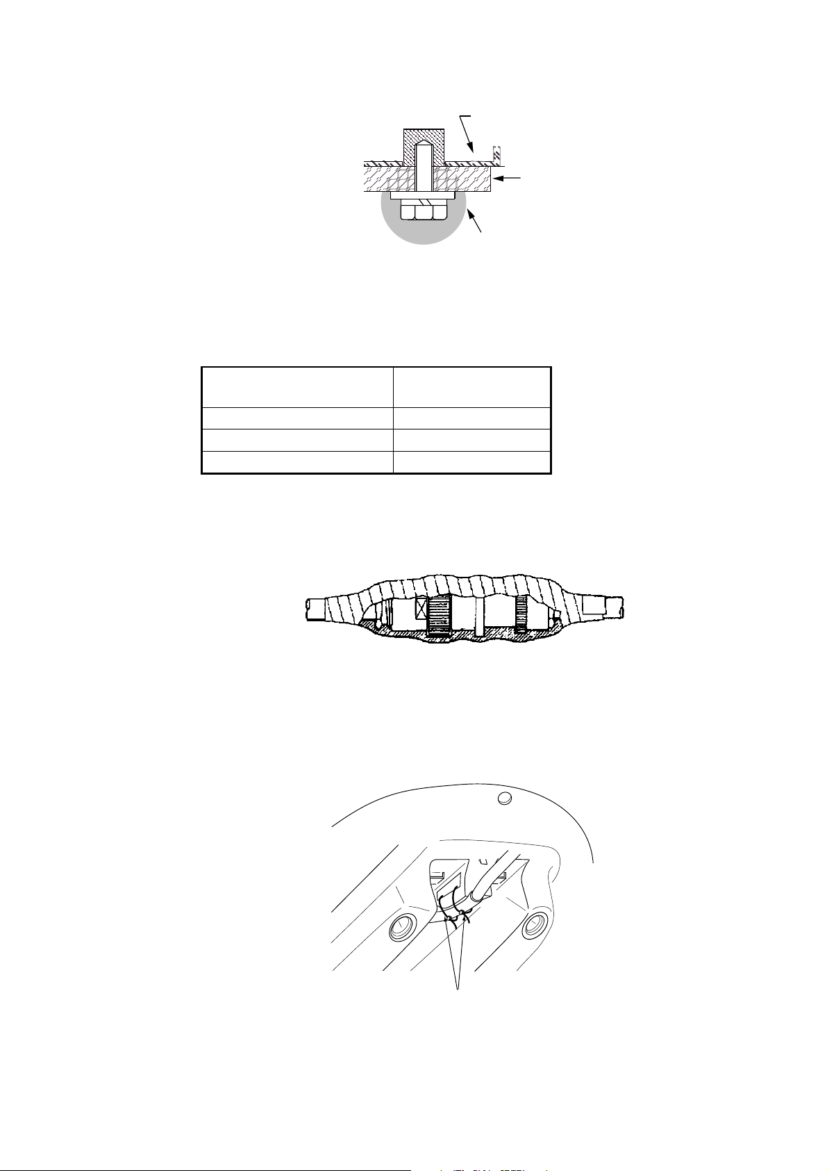
3. Coat exposed parts of nuts, bolts and washers with silicone sealant.
Radome
base
Platform
Coat with
silicone sealant.
Coating bolt, nut and washers with si licone sealant
4. Connect the three coaxial cables coming from the antenna unit to the
appropriate coaxial cables on the antenna cable, referring to the table below.
Cable from antenna
(no. marked on cable)
ANT 1 No color
ANT 2 Yellow
ANT 3 Red
TTPX6-3D2V-15M
Cable
For TNC-PS-3D-15, cable labels are provided from cable 1, 2 and 3 to
differentiate between then.
5. Cover the antenna connectors with vulcanizing tape and vinyl tape, for
waterproofing. Tie tape ends with a cable tie.
Waterpr oofing the antenna connector
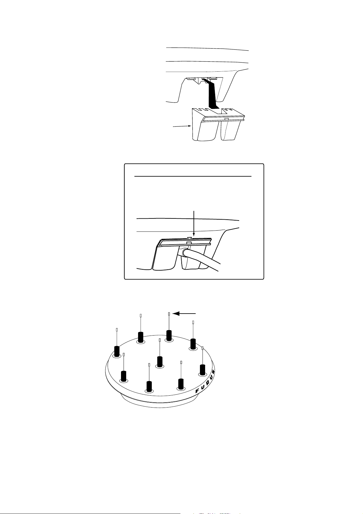
6. Set the joints of the coaxial cables into the cavity in the antenna base.
7. Pass two cable ties (long life, temperature resistant type, local supply)
through the hole shown in the figure below. Fasten them at the locations
shown in the figure below.
Cable Tie
How to fasten the antenna cab le
1-5
Page 16
1. INSTALLATION
8. Set the “cable cover” to the antenna base as shown in the figure below.
Cable Cover
How to ins er t the cable cover
HOW TO REMOVE CABLE COVER
Insert slotted-head
screwdriver here to
remove cable cover.
9. If necessary, attach nine “bird-repellent fixtures” (supplied) to the antenna
cover as shown below. Use the paper pattern to position the fixtures.
Bird-repellent fixture
N
U
R
U
F
Antenna uni t
10. Follow paragraph 1.6 to set up the equipment. If the status display shows
“OK” the installation Is suitable. If OK is not displayed, relocate the antenna.
1-6
Page 17
1.2.2 Antenna unit SC-603
Note: “Bird-repellent fixtures” (supplied) may be attached to each antenna
element and the Antenna Cover to prevent birds from alighting on the
antenna. If it is more convenient to attach them before fixing the antenna
unit to the mounting location, do step 10 in “Welding the antenna unit”
before fixing the antenna unit.
Mounting
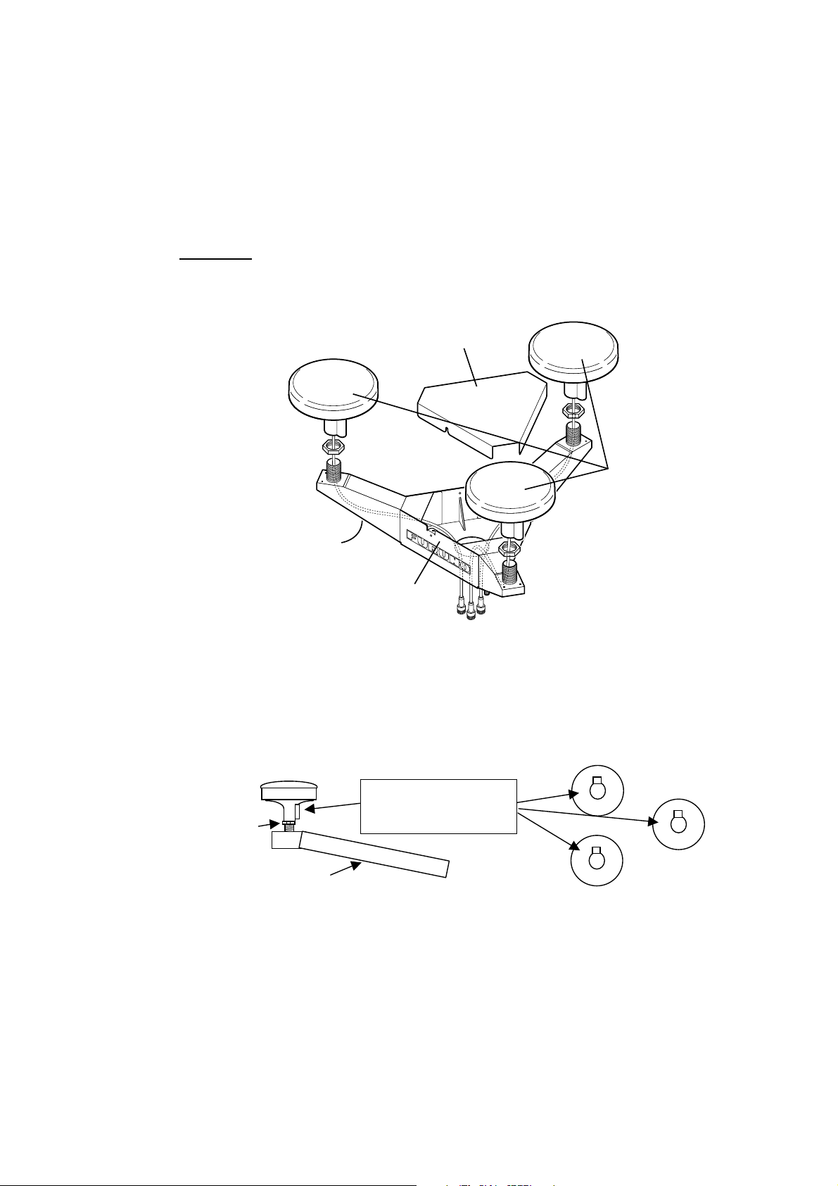
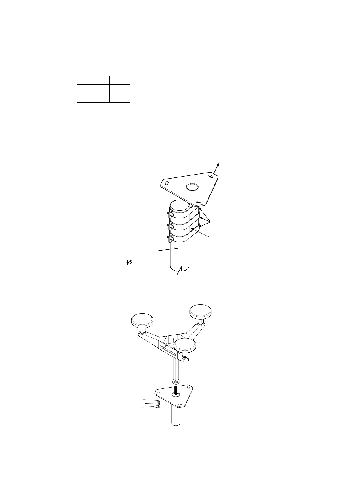
1. Screw in three antenna elements in the Antenna Base. Remove Antenna
Cover and Arm Cover.
1. INSTALLATION
Antenna Cover
2
Antenna
3
Arm Cover
(Below arm)
Antenna Base
1
Element
Antenna uni t SC-603
2. Pass the coaxial cable from each antenna element through the center of the
respective arm and then through the hole at the center of the antenna unit.
3. Orient the three antenna elements so that the protrusion on each faces the
bow.
BOW
Orient the three antenna
elements so the protrusion
Nut
Arm Cover S
on each faces the bow.
How to ori ent the antenna elem ents
1-7
Page 18
1. INSTALLATION
4. Making sure each antenna element is correctly oriented, fix each with its nut.
Write the corresponding arm number on each coaxial cable, using a magic
marker. (When connecting with the coaxial cables from the processor unit it is
necessary to match correct antenna element number with coaxial cable
color.)
Arm [1] 1
Arm [2] 2
Arm [3] 3
5. Temporarily fix the pedestal and support plate to the antenna mast as shown
in the illustration below. (The pedestal and support plate will be welded to the
antenna mast after confirming that the installation site is suitable, following
paragraph 2.6.)
Note: If U-bolts are used to temporarily fix the pedestal and support plate,
DO NOT overtighten them – overtightening may deform the pedestal.
BOW
PEDESTAL
Clamp
Support Plate
Antenna Mast
(Local supply
(f50 mm or more)
How to temporarily fix the support plate and pedestal t o the antenna mast
6. Set the antenna unit to the pedestal.
2
3
1
Coaxial Cable Identification
Arm [1]: 1
Arm [2]: 2
Arm [3]: 3
1-8
Flat Washer
Spring Washer
Nut
Fixi ng antenna unit to pedestal
Page 19
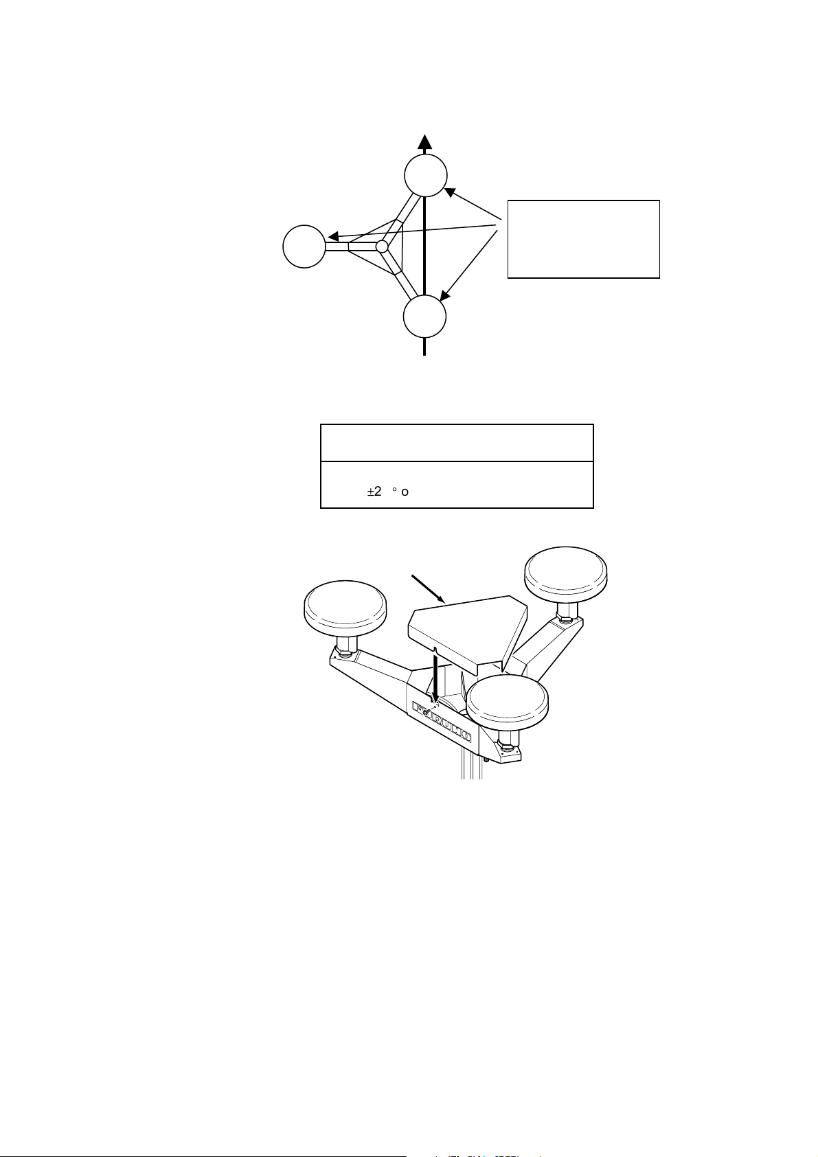
7. Orient the antenna unit as shown in the illustration below.
BOW
Antenna
Element
2
A number is inscribed
on each antenna arm.
PORT
Antenna
Element
3
Antenna
Element
1
This is the antenna
element number.
The bow mark is between
antenna element [1] and [2].
Face the bow mark towards
the bow
Orienting the antenna uni t (top view)
1. INSTALLATION
NOTICE
The antenna unit should be positioned
within
±
2.5° of the bow.
8. Fasten the Antenna Cover with three screws.
Antenna Cover
3
1
Antenna uni t SC-603
9. Follow the instructions in the paragraph 2.6. If the satellite tracking status
display shows “OK,” the installation site is suitable. Weld the antenna unit to
the antenna mast as shown in the next paragraph.
2
1-9
Page 20
1. INSTALLATION
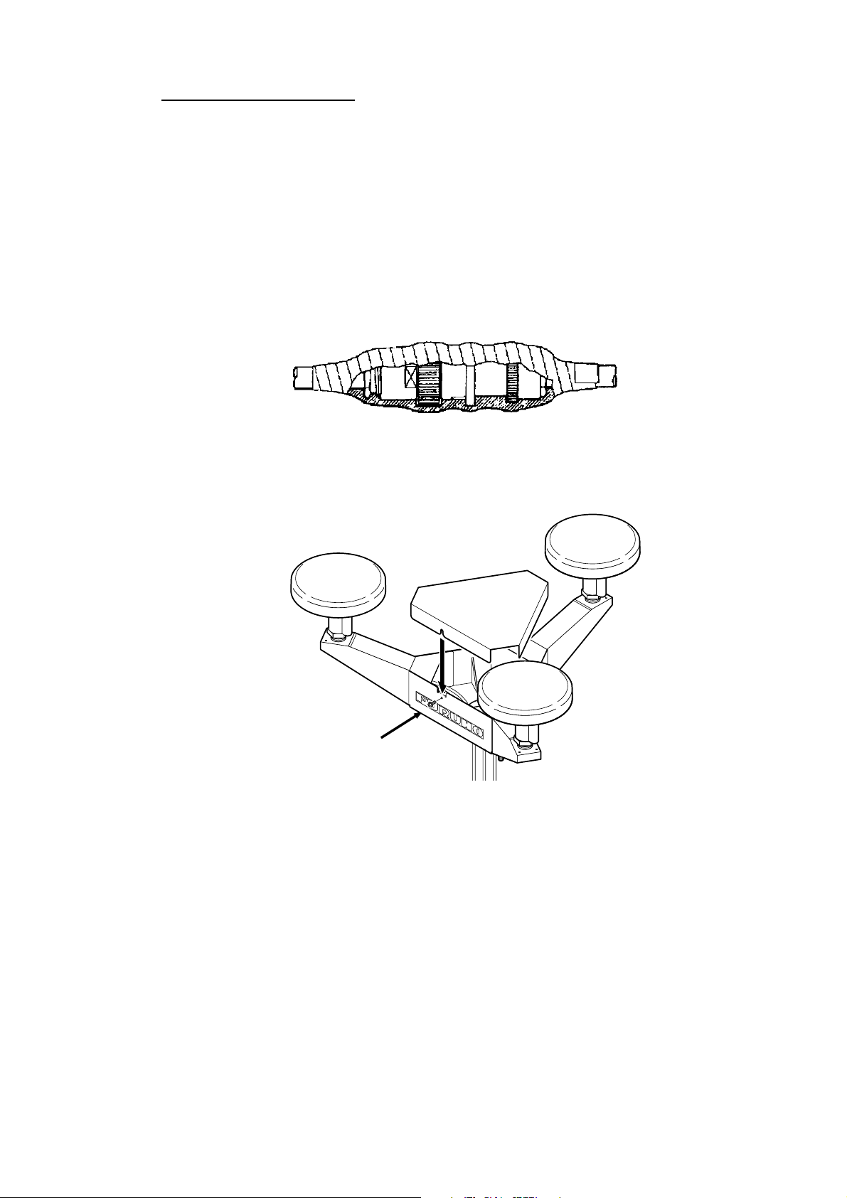
Welding the antenna unit
The antenna unit may be welded to the antenna mast if the satellite status
display shows “OK.”
1. Unfasten the coaxial cables and dismount the antenna unit.
2. Weld the pedestal and support plate to the antenna mast. Remove the
clamps used to temporarily fasten the pedestal and support plate.
3. Fasten the coaxial cables and fix the antenna unit.
4. Wrap the antenna connector with self-vulcanizing tape and then vinyl tape for
waterproofing as shown in the illustration below. Tie tape ends with cable ties
to prevent unraveling.
Waterpr oofing the antenna connector
5. Coat the three screws fixing the Antenna Cover S with Three Bond 1211
(supplied).
2
3
Coat screws with
ThreeBond (supplied).
1
Antenna uni t SC-603
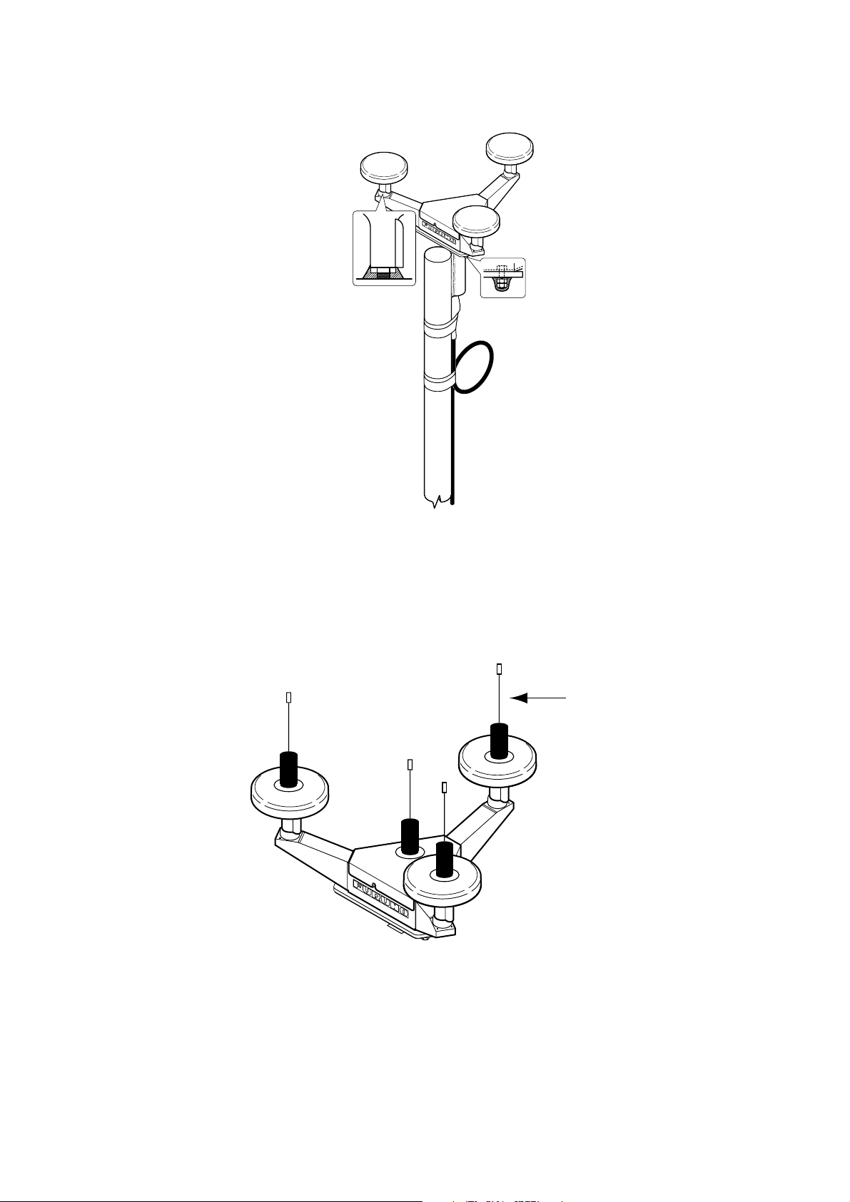
6. Look at the heading indication on the display. If the heading error is between
5° and 10°, loosen the nut at the center of the antenna unit and adjust
antenna orientation, while watching the heading indication on the display.
1-10
Page 21
1. INSTALLATION
7. Make a loop in the antenna cable as shown in the illustration below. Fasten
the antenna cable to the antenna mast with cable ties.
Coat bolt threads with
Coat with Three
Bond 1211 (supplied).
Fix antenna cable.
Three Bond. Fasten bolt
with nuts and then coat
nuts with Three Bond also.
Fastening the antenna cable
8. Coat bolt threads and nuts at the bottom of each antenna element with Three
Bond 1211.
9. Paint pedestal and support plate with anti-corrosive paint.
10. If necessary, attach the “bird-repellent fixtures” (supplied) to each antenna
element and the Antenna Cover S as shown below.
Bird-repellent fixture
Antenna element
1-1 1
Page 22
1. INSTALLATION
1.3 Installing the Processor Unit
The processor unit should be mounted aligned with the ship’s fore-and-aft line. It
can be mounted on the deck, bulkhead, or on the underside of a desk. Choose a
mounting location which allows you to easily view the power lamp on the top of
±
the unit and which is within
1.3.1 Bulkhead mount
The processor unit is shipped from the factory ready for bulkhead mounting.
Orient the processor unit as shown below and fix it to the mounting location with
four tapping screws (M5x20). You will set the orientation later on the menu.
Reference Direction
2.5° of the ship’s fore-and-aft line.
Bulkhead
Mount processor unit so
reference direction is within
±
2.5° of fore-and-aft line.
Direction D
Mounting Method: "Wall"
(Bulkhead)
Mounting Direction: D
Name Plate (other side)
Direction
A
Direction
C
Mounting Method: "Wall"
(Bulkhead)
Mounting Direction: A
Direction B
Mounting Method: "Wall"
(Bulkhead)
Mounting Direction: C
Bulkhead m ount
Mounting Method: "Wall"
(Bulkhead)
Mounting Direction: B
1-12
Page 23
1.3.2 Deck mount
Orient the processor unit as shown below and fix it to the mounting location with
four tapping screws (M5x20). You will set the orientation later on the menu.
Mount processor unit
so reference
direction is within
±
2.5° of
fore-and-aft line.
Name plate
Connectors
Processor Unit, top view
Reference Direction
POWER switch
(power lamp)
1. INSTALLATION
Port
Port
Bow
Stern
Bow
Bow
Mounting Method: "Floor"
(Deck)
Mounting Direction: A
Starboard
DIRECTION "A" DIRECTION "B"
Mounting Method: "Floor"
(Deck)
Mounting Direction: C
Starboard
Port
Stern
Bow
Port
Mounting Method: "Floor"
(Deck)
Mounting Direction: B
Starboard
Mounting Method: "Floor"
(Deck)
Mounting Direction: D
Starboard
DIRECTION "C" DIRECTION "D"
Stern
Stern
Processor u nit orientation, deck mount ing
1-13
Page 24

1. INSTALLATION
1.3.3 Installation on the underside of a desk
The processor unit may be mounted on the underside of a desk as shown in the
figure below. Do not install it on the overhead.
Desk
Name Plate
Installation of processor unit on the und er s ide of a desk
Reference Direction
Mount processor unit so
reference direction is
within
fore-and-aft line.
±
2.5° of
Port
POWER switch
(power lamp)
Bow
Mounting Method: Invert
Mounting Direction: A
Starboard
DIRECTION "A" DIRECTION "B"
Stern
Bow
Mounting Method: Invert
Mounting Direction: C
Connectors
Processor Unit, rear view
Port
Bow
Stern
Bow
Name plate (other side)
Mounting Method: Invert
Mounting Direction: B
Starboard
Mounting Method: Invert
Mounting Direction: D
Port Starboard
DIRECTION "C" DIRECTION "D"
Stern
1-14
Port
Stern
Mounti ng on underside of desk
Starboard
Page 25
1.4 Installing the Display Unit
1.4.1 Desktop, overhead mounting
1. Fasten the hanger to the mounting location with four tapping screws
(supplied). See the outline drawing for mounting dimensions.
2. Screw the knobs into the display unit.
3. Set display unit to the hanger and tighten the knobs.
4. Run the ground wire between the ground terminal on the display unit and the
ship’s superstructure.
1. INSTALLATION
1.4.2 Flush mount
Two types of flush mounts are available. See the outline drawing at the back of
the manual for details.
Flush mount “F”
Flush mount “ F” kit Type: OP20-29, Code No: 000-041-405)
Name Type Code No. Qty
Cosmetic Panel 20-016-1051 100-251-370 1
Tapping Screw 5X20 000-802-840 4
Hex Bolt M6X12 000-862-127 2
Spring Washer M6 000-864-260 2
1. Make a cutout in the mounting location. The dimensions are 183(W) x 92(H)
mm.
2. Fasten the cosmetic panel to the display unit with hex bolts and spring
washers.
3. Fasten the display unit to the mounting location with tapping screws.
Desktop
Display unit mounting methods
Overhead
1-15
Page 26
1. INSTALLATION
Flush mount “S”
Flush mount “ S ” kit Type: OP20-17, Code No.: 000-040-720)
Name Type Code No. Qty
Flush Mount Fixture 20-007-2401 100-183-190 2
Wing Bolt M4X30 000-804-799 4
Wing Nut M4 000-863-306 4
Hex Bolt M6X12 000-862-127 2
Spring Washer M6 000-864-260 2
1. Make a cutout in the mounting location. The dimensions are 167(W) x 92(H)
mm.
2. Place the display unit in the cutout.
3. Fix the display unit to the two flush mount fixtures with hex bolts and spring
washers.
4. Screw the butterfly nut on the butterfly bolt.
5. Fix the display unit with the butterfly bolt and then tighten the butterfly nut.
Flush mount “S”
1-16
Page 27
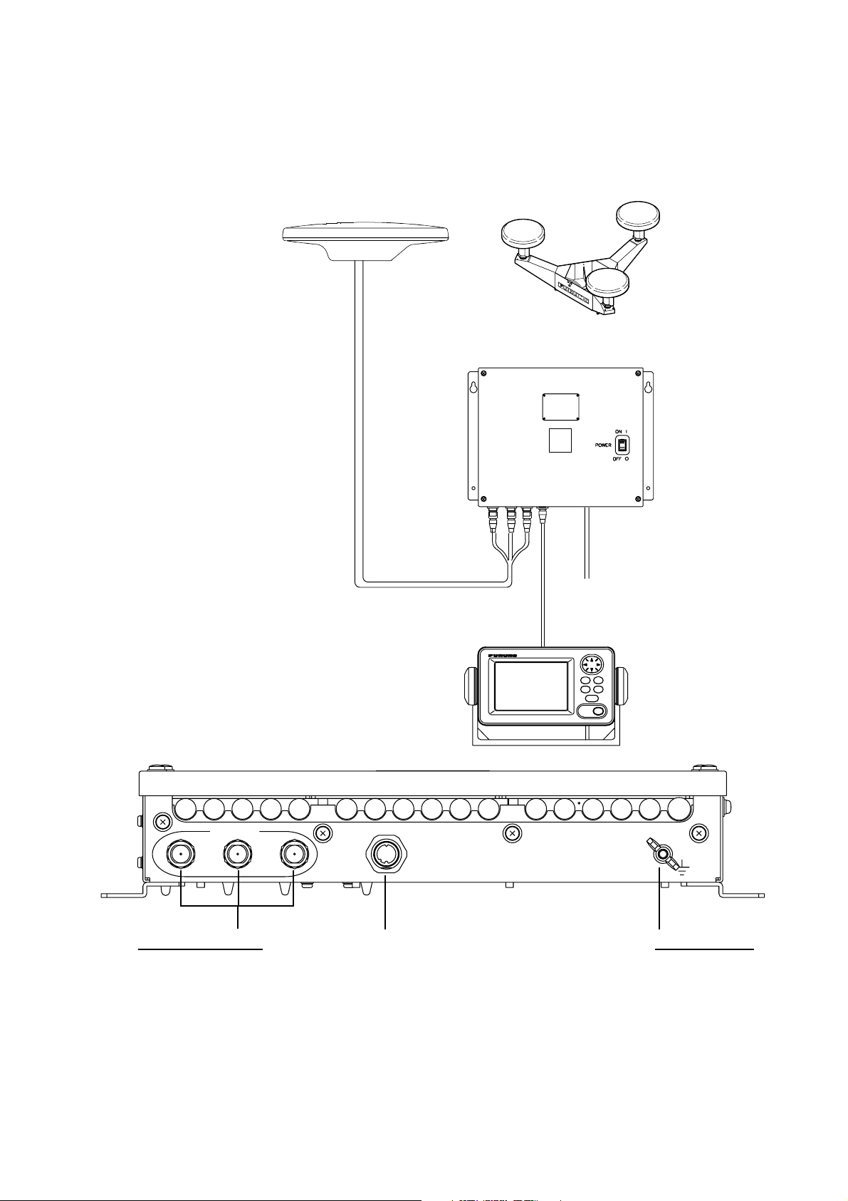
1.5 Wiring
This section covers general wiring. For further details see the interconnection
diagram at the back of this manual.
ANTENNA UNIT
SC-303
OR
ANTENNA UNIT
SC-603
3
PROCESSOR UNIT
SC-501
1. INSTALLATION
2
GPS ANT
1
ANTENNA Terminals
GPS ANT1: No color
GPS ANT2: Yellow line
GPS ANT2: Red line
(using cable TPPX6-3D2V-15M)
32
TPPX6-3D2V-15M, 15m
or
TNC-PS-3D-15 (3 pcs.)
DISPLAY UNIT
SC-502
DISPLAY
Cable from display
DPYC 1.5
12-24 VDC
MJ-A7SPF0006-100,
10m
*
Ground Terminal
Connect IV-2.0 sq
ground wire to
ship’s superstructure.
Wiring
1-17
Page 28
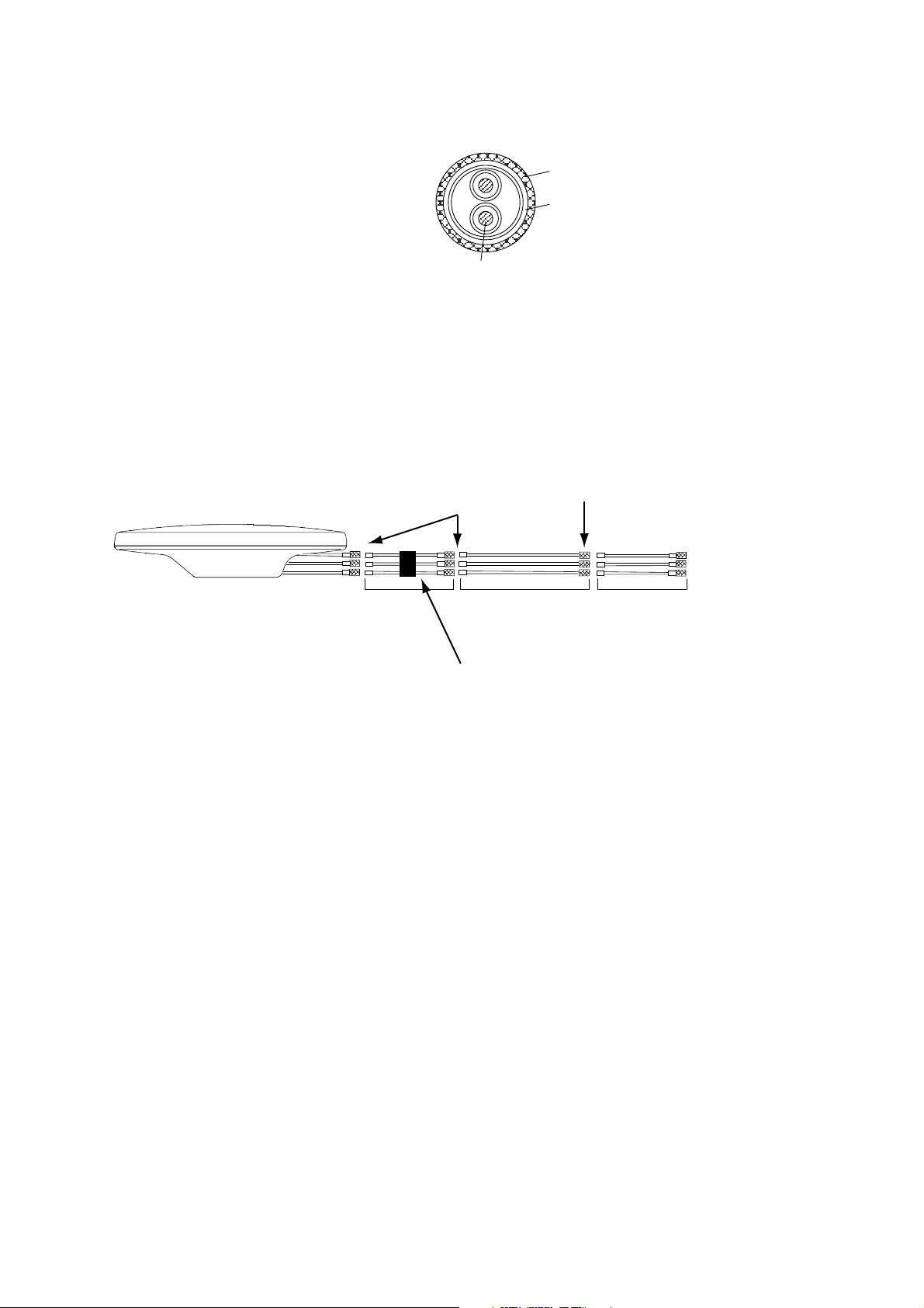
1. INSTALLATION
Note 1: Use cable type DPYC-1.5 (or equivalent) for the power cable.
Note 2: The optional antenna cable set (CP20-01700 or CP20-01710) allows
DPYC-1.5
Armor
Sheath
φ =
11.7 mm
Conductor
S = 1.5 mm
φ = 1.56 mm
2
Sectional view of coaxial cable DPYC-1.5
you to extend antenna cable length to 30 m (50 m). See next page for
how to attach the connector.
Wrap each
junction with
tape.
Attach connector
N-P-8DFB in field.
(OR Open-type
Antenna)
1 m
30 or 50 m
Bind the coaxial cables with vinyl tape.
1 m
How to ins tall the opti onal antenna cable s et
To processor
unit
1-18
Page 29
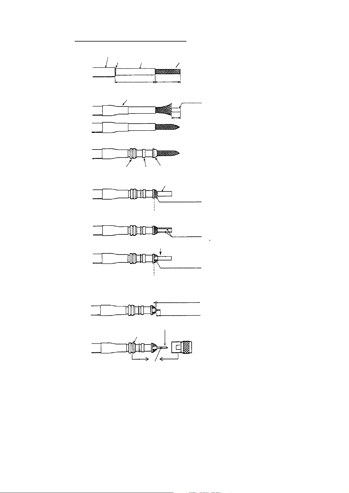
How to att ach connector N-P-8DFB
1. INSTALLATION
Outer Sheath
Armor
Cover with heat-shrink tubing and heat.
Clamp Nut
Inner Sheath Shield
50
Gasket
(reddish
brown)
Trim shield here.
30
Clamp
Aluminum Foil
10
(Dimensions in millimeters.)
Cut off insulator and core by 10 mm.
Twist shield end.
Slip on clamp nut,
gasket and clamp as shown left.
Fold back shield over clamp and trim.
Cut aluminum foil at four places,
90 from one another.
Fold back aluminum foil onto shield
and trim.
Expose the insulator by 1 mm.
Expose the core by 5 mm.
Slip the pin onto the conductor.
Solder them together through the
hole on the pin.
Insert the pin into the shell.
Screw the clamp nut into the shell.
(Tighten by turning the clamp nut.
Do not tighten by turning the shell.)
Trim aluminum
tape foil here.
Clamp Nut
Solder through
the hole.
Insulator
1
5
Pin
Shell
How to attach connector N-P-8DFB
1-19
Page 30

1. INSTALLATION
1.6 Initial Settings
Follow the procedures in this section to enter initial settings.
NOTICE
Improper menu settings may stop output of
data and display the message "RATE
ERROR." Be sure to enter correct data.
1.6.1 Confirming satellite status
Press the [SAT STATUS] key.
Satellites used for
measurement
SAT TRACKING STATUS
Satellites
being
tracked
TIMER 5 '52" OK
NO. GOOD STATUS
GPS1 8 8 D3D
GPS2 7 7 D3D
GPS3 8 8 D3D
"OK" displayed when
the "GOOD" column
shows that the number
of satellites acquired is
five or more.
"3D" shown when no
beacon receiver is used.
"W3D" shown when
receving W AAS.
Satellite tracking status display
When the system is turned on for the first time it is in the “cold-start” state, which
means there is no satellite data (almanac data) stored. In this condition it takes
about 12 minutes to find heading. When heading is found the display shows
“OK.” The timer at the top left corner of the screen shows time since power on. If
OK is not displayed within 30 minutes after turning on the power, the antenna
mounting location may not be suitable. Suspect that the number of satellites in
view is less than five due to signal blockage. (For the open-type antenna, loosen
the nut at the center of the antenna unit to adjust antenna orientation.) Resolve
the problem and then recheck tracking status.
If the heading error is between 5° and 10°, adjust orientation of the antenna unit,
while watching the heading indication on the display.
1-20
Page 31

1.6.2 Choosing mounting method
1. Turn on the processor unit and then press the [MENU] key to show the menu.
MAIN MENU
1. INSTALLATION
ALARMS
MESSAGES
GPS SETUP
SYS SETUP
SOFT VER.
OTHERS
SATELLITE
WAAS/DGPS
I/O SETUP
INST MENU
ERASE
TRIP MENU
Main menu
2. Use the Omnipad (
) to choose “INST MENU” and then press the [ENT]
key.
INSTALLATION SETUP
MOUNTING : WALL
DIRECTION : A
LANGUAGE : ENG
ROLL OFFSET : 0.0
PITCH OFFSET : 0.0
Installation setup m enu
3. “MOUNTING” is selected; press the [ENT] key.
4. Use the Omnipad to choose the mounting method: “FLOOR”, “WALL” or
“INVERT” as appropriate.
5. Press the [ENT] key.
6. “DIRECTION” is selected; press the [ENT] key.
7. Use the Omnipad to choose mounting direction (“A ”, “B ”, “C” or “D”) as
appropriate. Refer to section 1.3.
8. Press the [ENT] key.
1-21
Page 32

1. INSTALLATION
1.7 Connection of External Equipment
1.7.1 General wiring
All external equipment are terminated on the MAIN Board inside the processor
unit. Turn off the power and unfasten four screws to remove the cover. Connect
wiring from external equipment referring to the interconnection diagram. Use the
terminal opener supplied to open terminal blocks, referring to the instructions
below.
Recommended Cables*:
Power cable: DPYC-1.5
IEC 61162 equipment: TTYCS-1
AD-10 equipment: TTYCS-1Q
* Or equivalent
How to insert cores in terminal blocks
Opener
1. Insert opener.
2. Press opener.
3. Insert core.
4. Release opener.
Power Cable
From top: Analog Roll, Analog Pitch, 2-pole. See Note.
LOG/ALARM (Contact signal, 6-pole)
DATA IN (AD-10/IEC 61162-1/2, 5-pole)
BEACON EXT (RTCM SC-104, 3-pole)
DATA OUT6 (AD-10, 4-pole)
DATA OUT1-DATA OUT5 (AD-10/IEC 61162-1/2, 4-pole)
Processor unit, cover opened
Note 1: Attach labels (supplied) to cables to differentiate between them.
Note 2: A plastic sheet is placed across the cable glands of the processor unit to keep out
foreign material. Cut out holes in the plastic where cables are to be lead in.
Note 3: Roll, pitch analog out voltage [V] = 0.0785 x θ (deg.) + 3.5 (θ = roll, pitch angle)
Output example
Roll or pitch angle Analog out voltage
0 [deg] 3.5 [V]
5 [deg] 3.8925 [V]
10 [deg] 4.285 [V]
20 [deg] 5.07 [V]
1-22
Page 33

1.7.2 Fabrication of cables
Cable Sectional view, fab rication
Power
cable
DPCY-1.5
(or
equivalent)
Cable for
IEC 61162
format
equipment
(JIS cable
TTYCS-1
or
equivalent)
Cable for
AD-10
format
equipment
((JIS cable
TTYCS-1Q
or
equivalent)
Armor
Sheath
φ = 11.7 mm
φ = 10.1 mm
SECTIONAL VIEW (TTYCS-1)
φ = 11.3 mm
SECTIONAL VIEW (TTYCS-1Q)
Conductor
S = 1.5 mm
φ = 1.56 mm
SECTIONAL VIEW
Conductor
S = 0.75 mm
φ = 1.11 mm
Shield
Conductor
S = 0.75 mm
φ = 1.11 mm
2
Armor
Sheath
Shield
2
Armor
Sheath
2
Crimp-on lug
FV1.25-5
50
Sheath
6
Vinyl tape
FABRICATION
80
Braided shield
Four cores on TTYCS-1Q
6
Ground wire (70)
Ground wire: Fasten to fixing screw on pcb.
Armor
Cut the sheath.
15
8
1015
Vinyl tape
FABRICATION
50
Lay in clamp
where paint
was removed.
3
Armor
Twist and cut.
Solder
1. INSTALLATION
Remove paint by
40 mm, clamp this
part in cable clamp.
NOTE ON WIRING
1) Ground both this unit
and external equipment.
2) Fabricate braided shield of external equipment as follows:
- IEC 61162-1 input, AD-10 input (photo coupler): Connect to FG(frame ground).
- IEC 61162-2 input (RS-422/485): Connect to SG(signal ground).
Note: The power section of this equipment is insulated so the potential of SG and FG are the
same. If the shielding is not properly done, the data output IC may be damaged.
1-23
Page 34

1. INSTALLATION
(This page intentionally left blank.)
1-24
Page 35

2 OPERATION
2.1 Controls
MENU key: Opens menu.
DISP key: Selects display; closes menu.
HOW TO REMOVE THE COVER
Press here and pull toward
you to remove cover.
Omnipad: Selects menu items; shifts cursor.
MENU
DISP
SATELLITE
COMPASS
HDG
SETUP
ENT
DIM
SAT
STATUS
ENT key: Terminates key input.
DIM key: Adjusts panel illumination,
display contrast.
HDG SETUP key: Chooses heading
source.
SAT STATUS key: Shows satellite tracking status.
See the illustration on page 1-20.
Display unit
NOTICE
Reducedaccuracymayoccurincase
ofunfavorablesatelliteconstellation,
worsenedHDOP,etc.
Alwaysconfirmpositionagainstother
navigationdevicestoverifyreliability.
2-1
Page 36

2. OPERATION
2.2 Turning the Power On/Off
Use the power switch on the processor unit to turn the power to the display unit
on and off.
Processor u nit
A beep sounds and the display starts up with the last-used display.
Note: If backup heading data is used the heading indication flashes until faithful
heading data becomes available.
POWER
Switch
2.3 Panel Illumination, Display Contrast
1. Press the [DIM] key.
DIMMER (1-8)
4
CONTRAST (0-63)
45
EXIT: [ENT]
Dialog box for adjustment of panel illumination, dis play c ontrast
2. Press ▲ or ▼ to adjust panel illumination (dimmer).
3. Press ◄ or ► to adjust display contrast.
4. Press the [ENT] key.
2-2
Page 37

2.4 Choosing a Display
Use the [DISP] key to show a display desired.
2.4.1 Descri pt io n of di spl ays
Heading display
The heading display shows heading, course, speed, date, time and
position-fixing status. The heading status mark changes in the sequence shown
below. The “final calculations” mark disappears after heading becomes reliable,
which is approximately 90 seconds after that mark appears.
Position-fixing status indications
2D 2D GPS position fix
3D 3D GPS position fix
D2D 2D DGPS position fix
D3D 3D DGPS position fix
SIM Simulation mode
W2D WAAS 2D position fix
W3D WAAS 3D position fix
Positionfixing
status
04 - 1 - 15
3D
Date
(day/month/year)
Time
23:54:13
2. OPERATION
Heading Calculation Status
= Acquiring satellite
= Calculating heading
= Final calculations
When the data
of external sensor is input,
EXT (in reverse video) replaces
HDG on the Heading, Nav data,
Steering and Compass displays.
HDG
SOG
.00
Speed over
ground
832
kt
COG
°
0
.
°
213
.4
Course over
ground
Heading
Nav dat a display
The nav data display shows position in latitude and longitude, speed, heading,
date, time and position-fixing status.
HDG
00:00:00
’0.°0
’0.°0
728
N
E
.0
Position in
Latitude, Longitude
°
3D
SOG
04 - 1 - 15
00 00
00 00
kt
.00
Nav data di s play
2-3
Page 38

2. OPERATION
Steering display
The steering display shows heading in digital and analog form. SOG and COG
are also indicated. Note that COG accuracy is low when the own ship speed is
low. The faster the speed, the more accurate the COG.
07:54
°
0
.
Lubber’s mark
°
213
.4
Bearing
scale
3D
HDG
SOG
782
260250 270 280 290 300
kt
.00
COG
St eer ing display
Compass display
The compass display shows heading by compass direction. Pitch and roll are
also indicated. The compass rose rotates with heading.
Pitching
Rolling
3D
23:24:01
0
HDG
+
0
PIT
+
0
ROL
.0
°
°
°
NW
W
N
NESW
ES
SE
Own ship symbol
Compass display
ROT (Rate-of-Turn) display
The ROT display provides digital and analog indications of rate of turn.
3D
2030 10 0 10 20 30
ROT
scale
ROT
PORT
ROT
221
.
STBD
°/min
ROT display
2-4
Page 39

2. OPERATION
Speed display
Depending on the setting of DISTANCE DISP on the TRIP menu, the Set and
Drift display or the Distance Run display is shown. The current indication
requires a Doppler Speed Log.
Ground speed
3D
SOG
211
kt
STW
kt
CURRENT
.
222
.
°
8
36
.
Current (direction, speed)
2
2
.
2
.
kt
5
SOG/STW display
3D
SOG
211
kt
STW
kt
DISTANCE
.
222
.
54768
Distance run
2
2
.
.
nm
Lateral
speed
Speed
relative to
water
2-5
Page 40

2. OPERATION
2.5 Alarm Setup
The SC-50 can alert you with audible and visual alarms when GPS signal,
DPGS signal and WAAS signal are lost. To set the DGPS alarm, do the
following:
1. Press the [MENU] key to show the menu.
2. Choose ALARMS and then press the [ENT] key.
ALARMS
BUZZER : LONG
DGPS : OFF
Alarm menu
3. BUZZER is selected; press the [ENT] key.
SHORT
LONG
CONSTANT
Buzz er options
4. Use ▲ or ▼ to choose buzzer type desired and then press the [ENT] key.
SHORT: Two short beeps
LONG: Three long beeps
CONSTANT: Continuous beep
5. Press the [ENT] key.
6. DPGS is selected; press the [ENT] key.
OFF
ON
DGPS alarm options
7. Use ▲ or ▼ to choose OFF or ON as appropriate.
8. Press the [ENT] key.
9. Press the [DISP] key to close the menu.
2-6
Page 41

2.6 Confirming Satellite Status
You can check the receiving condition of each antenna unit as follows:
1. Press the [MENU] key to open the menu.
2. Choose SATELLITE and then press the [ENT] key.
Positionfixing
status
North
DOP
2. OPERATION
RX signal level
Horizontal bar extends
with signal strength.
Satellite whose signal
strength extends past
the first vertical line
is used for heading and
position calculation.
DOP
1. 5
23
14
18
- -
- -
- -
9
30
- -
- -
24
18
134
WAAS
Elevation
angle 5
°
Antenna
element
no.
3D
02
10
12
01
GPS1
Elevation
angle 45
08
N
07
06
04
05
°
Satellites shown in white on black are
used for calculation of heading and
position.
Satellite status display
3. Use ◄ or ► to choose antenna element for which to confirm receiving status.
4. Press the [DISP] key to close the menu.
2-7
Page 42

2. OPERATION
2.7 GPS Setup
The GPS SETUP menu smoothes position and course, averages speed, applies
position offset, and deactivates unhealthy satellites.
2.7.1 Displa yin g the GPS se tu p men u
1. Press the [MENU] key to open the menu.
2. Choose GPS SETUP and then press the [ENT] key.
GPS SETUP
SMOOTH POS : 0SEC
SMOOTH S/C : 5SEC
LAT OFFSET : 0.000’N
LON OFFSET : 0.000’E
DISABLE SV :
GPS SETUP menu
2.7.2 GPS SETUP menu description
SMOOTH POS (Smoothing position)
When the DOP (Dilution of Precision, the index for position-fixing accuracy) or
receiving condition is unfavorable, the GPS fix may change randomly, even if the
vessel at anchor. This change can be smoothed by averaging a number of GPS
fixes. The setting range is from 0 (no smoothing) to 999 seconds. The higher the
setting the more smoothing. However, too high a setting slows updating of
position.
SMOOTH S/C (Smoothing speed/course)
Ship’s speed and course are directly measured by receiving GPS satellite
signals, independent of positions. The data varies with receiving conditions and
other factors. You can reduce this random variation by increasing the smoothing.
The higher the setting the more that speed and course are smoothed. If the
setting is too high, however, the follow-up to actual values gets slower. The
setting range is from 0 (no smoothing) to 999 seconds.
LAT/LON OFFSET (L/L position offset)
2-8
If GPS fixes are erroneous while at anchor, enter a position offset to compensate
for position error. Consult a nautical chart to determine latitude and longitude
differences between the chart and GPS display. Enter that value as the offset.
Page 43

DISABLE SV (Disable satellite)
IEC
AD-10
Every GPS satellite is broadcasting abnormal satellite number(s) in its Almanac,
which contains general orbital data about all GPS satellites. Using this
information, the GPS receiver automatically eliminates any malfunctioning
satellite from the GPS satellite schedule. However, the Almanac sometimes may
not contain this information. If you hear of an inoperative satellite you can
disable it manually. Enter satellite number in two digits and then press the [ENT]
key. To restore a satellite, enter “00”.
2.8 Output Data
2.8.1 Heading
Heading data is output from the DATA OUT port on the processor unit, in IEC
61162-1/2 format.
1. Press the [MENU] key to open the menu.
2. Choose I/O SETUP and then press the [ENT] key.
2. OPERATION
OUTPUT DATA SETUP
DATA OUT1: AD-10
DATA OUT2: AD-10
DATA OUT3: IEC
DATA OUT4: IEC
DATA OUT5: IEC
LOG PULSE: 200 P/NM
OUTPUT DATA SETUP menu
3. Choose DATA OUT1 and then press the [ENT] key.
Data out opt ions
4. Use the Omnipad to choose AD-10 or IEC as appropriate and then press the
[ENT] key. If you choose AD-10, no further operation is required; go to step
18 to finish. For IEC go to the next step.
DATA OUT1
SENTENCE: HDG VTG ROT
HDT HDM
GLL ZDA VHW VBW
BAUD RATE: 4800BPS
INTERVAL: 100mS
NMEA VER: IEC ED2
HDG TALKER: GP
DATA OUT1 menu
2-9
Page 44

2. OPERATION
5. Choose SENTENCE and then press the [ENT] key.
6. Use the Omnipad to choose a sentence and then press the [ENT] key.
DATA OUT1
HDT VTG VHW
HDM GGA VBW
ROT GNS HVE
ATT GLL ZDA
VDR
DATA OUT1 menu, sentences
HDT: True heading (required for radar, AIS, ECDIS, etc.)
HDM: Magnetic heading (HDM is obtained in this equipment by adding the
magnetic variation to HDT.)
ROT: Rate-of-turn data
ATT: True heading, pitching, rolling (FURUNO’s proprietary sentence)
VDR: Set and drift
VTG: Course over ground and ground speed
GGA: Global positioning system (GPS) fix data
GNS: GNSS fix data
GLL: Geographic position, latitude/longitude
VHW: Water speed and heading
VBW: Dual ground/water speed
HVE: GPS antenna up-down motion amplitude (FURUNO proprietary
sentence)
ZDA: Time and date
OFF
ON
7. Use the Omnipad to choose OFF or ON as appropriate and then press the
[ENT] key. Sentences selected for output are marked with an asterisk.
8. Repeat steps 6 and 7 for other items. All sentences cannot be selected. The
message “SENTENCE OVERLOAD” appears when too many sentences
have been selected. Change settings as appropriate. For further information
see page 2-12.
9. Press the [MENU] key to return to the DATA OUT1 menu.
10. Choose BAUD RATE and then press the [ENT] key.
4800BPS
9600BPS
19200BPS
38400BPS
Baud rate opt ions
2-10
Page 45

2. OPERATION
25ms
100ms
200ms
1S
2S
11. Use the Omnipad to choose the baud rate of the equipment connected and
then press the [ENT] key.
12. INTERVAL is selected; press the [ENT] key.
Tx inter v al options
13. Use the Omnipad to choose appropriate output interval and then press the
[ENT] key.
14. Choose IEC VERSION and then press the [ENT] key.
IEC ED1
IEC ED2
NMEA 1.5
IEC, NM E A version options
15. Choose appropriate IEC (or NMEA) edition and then press the [ENT] key.
16. Choose HDG TALKER and then press the [ENT] key.
GP
HE
HN
HC
Heading talker options
17. Choose appropriate heading talker and then press the [ENT] key.
GP: GPS navigator talker
HE: North-seeking gyrocompass talker
HN: Non-north seeking gyrocompass talker
HC: Magnetic compass talker
18. Press the [DISP] key to close the menu, or press the [MENU] key to return to
the I/O SETUP menu to setup another output port.
2-1 1
Page 46

2. OPERATION
Outpu t sentence limitation
The number of sentences which can be output depends on baud rate and output
interval settings. The maximum number of characters per each data sentences
are shown in the table below and the total number of characters must satisfy the
formula shown below. The number of characters which can be output “N” is
calculated by the following formula
N <
T: Interval (s)
B: Baud rate
0.083 x T x B
Sentence and maximum number of character s
Sentence HDT HDM ROT ATT HVE VTG* GGA* GNS* GLL* ZDA* VHW* VBW* VDR*
No. of
Characters
19 19 21 34 23 46 66 62 47 36 44 45 35
*: Output is 1 s if interval set is shorter than 1 s.
For example, the baud rate is 4800 bps, interval is 100 ms (= 0.1 s). Therefore,
the number of characters is N <0.083 x 0.1(s) x 4800(bps) = 39.4.
Then, the number of characters which can be output is 39. For sentences
(sentences not having an asterisk in the table) where the output interval is
variable the number of characters is as shown in the table, however sentences
where the output interval is not smaller than 1 s (asterisk-marked sentences in
table) the number of characters which can be output is “number of characters in
table” x “setting interval.”
For the above settings the following applies:
•
If both HDT and HDM are selected the total number of characters is 19+19 =
38. Since the count is less than 39 both can be selected.
2-12
•
If both HDT and VTG are selected the total number of characters is
19+46x0.1=23.6. Since the count is less than 39 both can be selected.
•
If HDT, HDM and VTG are selected the total number of characters is
19+19+46x0.1=42.6. In this case, the message “SENTENCE OVERLOAD”
appears.
Page 47

2.8.2 Log pulse
This equipment provides SOG (speed over ground) in high accuracy. It converts
an SOG value to a pulse signal and outputs at the rate of 200 or 400 pulses/nm.
1. Press the [MENU] key.
2. Choose I/O SETUP and then press the [ENT] key.
3. Choose LOG PULSE and then press the [ENT] key.
4. Choose 200p/nm or 400p/nm as appropriate and then press the [ENT] key.
5. Press the [DISP] key to close the menu.
200p/nm
400p/nm
Log pulse opt ions
2. OPERATION
2-13
Page 48

2. OPERATION
2.9 System Setup
2.9.1 Geodetic data
Your unit is preprogrammed to recognize most of the major chart systems of the
world. Although the WGS-84 system (default setting) is the GPS standard, other
categories of charts in other datum still exist. Match the GPS datum with the
chart system you use.
1. Press the [MENU] key to open the menu.
2. Choose SYS SETUP and then press the [ENT] key.
DATUM : WGS84
UNITS : kt
TIME DIFF : +00:00
TIME DISP : 24 HOUR
TEST?
DEMO : OFF
EXCHANGE BATTERY?
SYSTEM SETUP
SYSTEM SETUP menu
3. Confirm that the cursor is selecting DATUM and then press the [ENT] key.
4. Choose WGS84 (GPS standard), WGS72 or OTHER according to the
nautical chart you use and then press the [ENT] key.
5. If you chose WGS72 or WGS84, press the [DISP] key to finish. For OTHER,
go to step 6.
6. Press the [ENT] key.
7. Use the Omnipad to enter chart number, referring to the geodetic chart list on
page A-2. Choose location with ◄ or ►; change value with ▲ or ▼.
8. Press the [ENT] key.
9. Press the [DISP] key to close the menu.
2-14
Page 49

2.9.2 Units of measurement
Distance/speed can be displayed in nautical miles/knots, kilometers/kilometers
per hour, or miles/miles per hour.
1. Press the [MENU] key to open the menu.
2. Choose SYS SETUP and then press the [ENT] key.
3. Choose UNITS.
4. Press the [ENT] key.
5. Choose unit of measurement combination desired; kt, km/h, mi/h.
6. Press the [ENT] key.
7. Press the [DISP] key to close the menu.
2.9.3 Using local time
GPS uses UTC time. If you would rather use local time, enter the time difference
(range: -13:30 to +13:30) between local time and UTC.
1. Press the [MENU] key to open the menu.
2. Choose SYS SETUP and then press the [ENT] key.
3. Choose TIME DIFF and then press the [ENT] key.
4. Press ▲ or ▼ to display + or – as appropriate.
5. Enter time difference with the Omnipad. Choose digit with ◄ or ►; change
value with ▲ or ▼.
6. Press the [ENT] key.
7. Press the [DISP] key to close the menu.
2. OPERATION
2.9.4 Time format
Time can be displayed in 12 hour or 24 hour format.
1. Press the [MENU] key to open the menu.
2. Choose SYS SETUP and then press the [ENT] key.
3. Choose TIME DISP and then press the [ENT] key.
4. Choose 12HOUR or 24HOUR as appropriate and then press the [ENT] key.
5. Press the [DISP] key to close the menu.
2-15
Page 50

2. OPERATION
2.9.5 Demonstration mode
The demonstration mode provides simulated operation of the equipment.
1. Press the [MENU] key to open the menu.
2. Choose SYS SETUP and then press the [ENT] key.
3. Choose DEMO and then press the [ENT] key.
4. Choose ON or OFF as appropriate and then press the [ENT] key.
5. Press the [DISP] key to close the menu.
The indication SIM appears at the top of the screen when the demonstration
mode is active. When the demonstration mode is first made active,
SIMULATION MODE appears when the power is turned on and it is erased
when any key is pressed.
2-16
Page 51

2.10 WAAS/DGPS Setup
1. Press the [MENU] key to open the menu.
2. Choose WAAS/DGPS and then press the [ENT] key.
STATION: Shows GOOD or NG.
WAAS/DGPS
MODE : GPS
WAAS SEARCH: AUTO 134
CORRECTIONS DATA SET: 00
DPGS STATION: AUTO
RATE: 000BPS
FREQ: 310.0kHz
STATION: GOOD* DATA:GOOD*
SIG. S: 55.2 dB* SNR: 22.0 dB*
3. MODE is selected; press the [ENT] key.
DATA: Shows GOOD or NG.
SIG. S: Signal Strength. A figure be tween 0
and 99 is shown. The higher the figure the
stronger the beacon signal.
SNR: Signal to Noise Ratio. A figure between
1 and 22 is shown. When your boat is in the
service area of a beacon station, SNR should
be 21 or 22. If the figure is below 21 the position
will be inaccurate. If this happens, check for radar
interference, poor ground and generator noise on own ship.
WAAS/DG P S menu
2. OPERATION
GPS
WAAS
DGPS
AUTO
Position fix mode options
4. Choose appropriate mode referring to the description below and then press
the [ENT] key.
GPS: Position fix by GPS
WAAS: Position fix by WAAS
DPGS: Position fix by DGPS (external beacon receiver required)
AUTO: Position fix in order of DGPS, WAAS and GPS
5. For WAAS or AUTO do as below. For DGPS go to step 6; for GPS go to step
8.
1) WAAS SEARCH is selected; press the [ENT] key.
AUTO
MANUAL
WAAS SEARCH options
2-17
Page 52

2. OPERATION
2) Use the Omnipad to choose WAAS satellite search method, AUTO or
MANUAL as appropriate. For MANUAL, press the [ENT] key, enter
appropriate WAAS satellite referring to the illustration below and then press
the [ENT] key.
Provider GEO Satellite Longitude
WAAS
EGNOS
POR (134) 178°E
AOR-W (122) 54°W
AOR-E (120) 15.5°W
IOR (131) 64.5°E
118°W 34.75°W 24.5°E 121.25°E
2°
122
AOR-W
54°W
Longitude Range Satellite
120.25
°
W to 33.75°W 122
119
35.75
°
23.5
2°
120
AOR-E
15.5°W
One-degree threshold
°
E to 117°W 134
°
W to 25.5°E 120
E to 122.25°E 131
2° 2°
131
IOR
64.5°W
134
POR
178°E
GEO satellite and coverage area
3) CORRECTIONS DATA SET is selected; press the [ENT] key.
CORRECTIONS DATA SET determines how to use the WAAS signal. Use
the default setting “00”. Do step 6 and 7 for DGPS.
6. Choose DPGS STATION and press the [ENT] key.
AUTO
MANUAL
AUTO/MANUAL options
7. Choose MANUAL or AUTO as appropriate and press the [ENT] key. For
AUTO got to step 8. For MANUAL do the following:
1) RATE is selected; press the [ENT] key.
50BPS
100BPS
200BPS
Baud rate options
2) Choose appropriate baud rate and press the [ENT] key.
2-18
Page 53

3) FREQ is selected; press the [ENT] key.
4) The cursor is selecting the hundredths digit so press ▲ or▼ to display
appropriate digit. Press ► to shift the cursor to the tenths place.
5) Set other digits appropriately.
8. Press the [DISP] key to close the menu.
2. OPERATION
2-19
Page 54

2. OPERATION
2.11 OTHERS Menu
The OTHERS menu contains the following items:
HOLD HDG DATA: Choose whether to display last-used heading data at power
on or not. Because this data is not reliable, the heading indication flashes to alert
you.
HDG RESTORATION: Choose how to restore GPS signal, automatically or
manually, after it is lost. For manual restoration, a key must be pressed to restart
heading output. This is done for safety purposes; for example, when an autopilot
is used.
HDG BACKUP : Choose how long to display backup data when the GPS signal
is lost. (This data is also output to external equipment.)
1. Press the [MENU] key to display the main menu.
2. Choose OTHERS and then press the [ENT] key.
OTHERS
HOLD HDG DATA: OFF
HDG RESTORATION : MAN
HDG BACKUP :
Others menu
3. HOLD HDG DATA is selected; press the [ENT] key.
5MIN
OFF
ON
4. Choose ON or OFF as appropriate.
5. Press the [ENT] key.
6. HDG RESTORATION is selected; press the [ENT] key.
MAN
2-20
AUTO
HDG REST ORATION options
7. Use the Omnipad to choose MAN or AUTO as appropriate and then press the
[ENT] key.
8. HDG BACKUP is selected; press the [ENT] key.
9. Choose 1, 2, 3, 4 or 5 minutes as appropriate.
10. Press the [ENT] key followed by the [DISP] key to close the menu.
Page 55

2.12 TRIP Menu
The TRIP menu functions to
•
Choose the indication to show on the SOG/STW display
•
Choose source of distance run
•
Reset distance run to zero
•
Smooth the tide drift indication
•
Enter smoothing for rate of turn and display range scale
1. Press the [MENU] key to display the main menu.
2. Choose TRIP MENU and then press the [ENT] key.
TRIP MENU
DISTANCE DISP : DSTNC
DISTANCE CALC: GPS
RESET DISTANCE?
DRIFT AVG : 10SEC
SMOOTH ROT: 2.5 SEC
ROT RANGE: 60°/MIN
2. OPERATION
TRIP menu
3. Choose DISTANCE DISP and then press the [ENT] key.
4. Choose what to display on the Speed display; distance run (DSTNC) or tide
direction and speed (DRIFT). Press the [ENT] key.
5. Choose DISTANCE CALC and then press the [ENT] key.
6. Choose the source for distance run; GPS, VLW (distance traveled through
water) or VBW (Dual ground/water speed). (VLW requires DS-80 type
Doppler speed log and VBW requires Current indicator or Doppler speed
log.) Press the [ENT] key.
7. Choose DRIFT AVG. and then press the [ENT] key.
8. If tide current and speed data is unstable, enter a smoothing figure to
stabilize the data. The higher the figure the more smoothed the data. A
setting between 0 (no smoothing) and 9999 (seconds) is available.
9. Choose SMOOTH ROT and then press the [ENT] key.
10. Use the Omnipad to enter rate of turn smoothing rate. Choose location with
◄ or ►; change value with ▲ or ▼. The setting range is 0.1 to 30.0
(seconds).
11. Press the [ENT] key.
12. Choose ROT RANGE and the press the [ENT] key.
13. Choose the range of the ROT graph from among 30, 60 and 90 (degree/min.)
and then press the [ENT] key.
14. Press the [DISP] key to close the menu.
2-21
Page 56

2. OPERATION
2.13 Resetting Distance Run
The distance run may be reset to zero as below when the source of distance run
is GPS or VBW.
1. Press the [MENU] key to display the main menu.
2. Choose TRIP MENU and then press the [ENT] key.
3. Choose RESET DISTANCE and then press the [ENT] key.
RESET DISTANCE?
ARE YOU SURE?
YES NO
RESET DISTANCE prom pt
4. Choose YES and then press the [ENT] key.
5. Press the [DISP] key to close the menu.
2.14 Choosing External Heading Source for Backup
Choose the source of heading data as below.
CAUTION
Never switch from internal to external
heading while the autopilot is in the
automatic mode. Change to the
manual mode before switching.
2. Press the [HDG SETUP] key.
HEADING SETUP
OFFSET : +000.0
(SERVICE ONLY)
HEADING : INT
INT HDG - - - . EXT HDG - - - . -
°
°
OFFSET : Heading offset. See service manual for instructions.
"SERVICE ONLY" means heading offset shown
for display only.
HEADING : Select heading source. Choose INT for normal use.
If a gyrocomapss is connected for primary means,
leaving this equipment as backup, choose EXT.
INT HDG : Bow heading. Includes offset.
EXT HDG : Heading fed from external equipment.
Heading set up menu
2-22
3. ”HEADING” is selected; press the [ENT] key.
4. Choose INT or EXT as appropriate. Normally choose INT. If own GPS sensor
is not working and a heading sensor such as a gyrocompass is available,
choose EXT.
5. Press the [ENT] key.
6. Press the [DISP] key to close the menu.
Page 57

3 MAINTENANCE,
TROUBLESHOOTING
WARNING
ELECTRICAL SHOCK HAZARD
Do not open the equipment.
Only qualified personnel
should work inside the
equipment.
3.1 Preventive Maintenance
Regular maintenance is important for good performance. A maintenance
program should be established and should include the following points.
•
Check connectors and ground terminal on the processor unit and display unit
for tightness.
•
Check ground terminal for rust. Clean or replace as necessary.
•
Check for water leakage in the antenna cable. Replace the cable if there are
signs of water leakage.
•
Remove dust and dirt from the display unit and processor unit with a dry, soft
cloth. For the LCD, wipe it carefully to prevent scratching, using tissue paper
and an LCD cleaner. To remove stubborn dirt, use an LCD cleaner, wiping
slowly with tissue paper so as to dissolve the dirt. Change paper frequently so
the dirt will not scratch the LCD. Do not use chemical cleaners for cleaning they can remove paint and markings.
3-1
Page 58

3. MAINTENANCE, TROUBLESHOOTING
3.2 Troubleshooting
This section provides basic troubleshooting procedures which the user may
follow to restore normal operation.
Troubleshooting
Symptom Cause Remedy
Cannot turn on the power.
Heading indication
changes randomly when
ship is at anchor or does
not change when ship
moves.
Heading output from
SC-50 does not appear on
external equipment.
Power cable on the
processor unit
Power supply failure Check the power supply.
Blown fuse Have a qualified
Sensor trouble Run the diagnostic test2 to
Connection between
SC-50 and external
equipment has loosened.
Sensor trouble Run the diagnostic test1 to
Firmly connect the power
cable
technician check the fuse.
determine cause.
Firmly fasten the
connector.
determine the cause.
If large heading error occurs or heading indication is frequently interrupted,
contact your dealer for advice.
3-2
Page 59

3.3 Diagnostics
Diagnostic test1
The diagnostic test1 checks the equipment for proper operation.
Note: Heading is not output during the diagnostic test, and this is communicated
with an appropriate message. After completing the diagnostic test, turn the
power off and on to update heading data.
1. Press the [MENU] key to open the menu.
2. Choose SYS SETUP and then press the [ENT] key.
3. Choose TEST? and then press the [ENT] key.
3. MAINTENANCE, TROUBLESHOOTING
TEST1
TEST2
TEST3
Test m enu options
4. Confirm that TEST1 is selected and then press the [ENT] key.
TEST START?
(STOP: PWR OFF)
ARE YOU SURE?
YES NO
Test start prompt
5. Press ◄ to choose YES and then press the [ENT] key. The test proceeds in
the sequence shown on the next page.
Note: The output port test (see next page) is intended for the service technician,
using a special test connector. If TEST1 is conducted without the test
connector, disconnect the DATA IN connector from the processor unit.
3-3
Page 60

3. MAINTENANCE, TROUBLESHOOTING
ROM, RAM, KEY TEST
OK shown for normal;
NG (No Good) shown for error
GPS receiver
Processor unit
Display unit
OUTPUT TEST
(for serviceman)
GPS1 OK OK PUSH KEY
GPS2 OK OK
GPS3 OK OK
CAL OK OK OK
DISP OK OK
CNT= (STOP: PWR OFF)
ROM RAM
Number of
times test
executed
After 3 sec.
AD-10 IEC
OUT1 - - - OUT2 - - - OUT3 - - - OUT4 - - - OUT5 - - - OUT6 - -
KEY TEST
Press each key one by
one. Pressed key’s name
appears here if key
is functioning properly.
To stop the test turn
off the power.
(For serviceman)
DISPLAY TEST
PROGRAM NUMBER
DISPLAY
After 5 sec.
B-EXT - DISP OK
All LCD segments go on 2 sec.,
All LCD segments go off 3 sec.
<LCD CHECK>
ALL ON 2 SEC.
ALL OFF 3 SEC.
SOFTWARE VERSION
DISPLAY 205-1342-**.**
PROCESS 205-1341-**.**
GPS1 4850263***
GPS2 4850263***
GPS3 4850263***
** Program
Version No.
3-4
CNT= (
STOP: PWR OFF)
ROM, RAM, KEY check appears after
3 sec.
Diagnosti c test sequence
6. Turn off the processor unit to quit the diagnostic test1.
Page 61

3. MAINTENANCE, TROUBLESHOOTING
Diagnostic test2
If the heading indication changes randomly when ship is at anchor or does not
change when the ship moves, run the test2 following the procedure below, with
the ship at anchor and satellite signal received.
Note: Heading is not output during the diagnostic test, and this is communicated
with an appropriate message. After completing the diagnostic test, turn
the power off and on to update heading data.
1. Press the [MENU] key to open the menu.
2. Choose SYS SETUP and then press the [ENT] key.
3. Choose TEST? and then press the [ENT] key.
TEST1
TEST2
TEST3
Test m enu options
4. Choose TEST2 and then press the [ENT] key.
TEST START?
(STOP: PWR OFF)
ARE YOU SURE?
YES NO
Test start prompt
5. Press ◄ to choose YES and then press the [ENT] key.
6. Press the [ENT] key twice. Rate and angle values are 0.0°. If the values
increase or decrease markedly (with ship at anchor), suspect rate sensor
trouble. Contact your dealer to request service.
TEST2
YAW ROL PIT
RATE
ANGLE
0.0
0.0
°
°
0.0
0.0
°
°
0.0
0.0
°
°
<STOP: PWR OFF>
TEST2 di s play
7. Turn off the processor unit to quit the diagnostic test2.
3-5
Page 62

3. MAINTENANCE, TROUBLESHOOTING
Diagnostic test3
This test checks the buzzer signal/contact for proper operation.
1. Press the [MENU] key to open the menu.
2. Choose SYS SETUP and then press the [ENT] key.
3. Choose TEST? and then press the [ENT] key.
4. Choose TEST3 and then press the [ENT] key.
TEST1
TEST2
TEST3
Test m enu options
TEST START?
(STOP: PWR OFF)
ARE YOU SURE?
YES NO
Test start prompt
6. Press ◄ to choose YES and then press the [ENT] key.
TEST3
ALARM: OFF
TEST3 menu
7. Press the [ENT] key.
OFF
ON
ALARM options
3-6
8. Choose OFF or ON as appropriate and then press the [ENT] key.
OFF: Buzzer sound goes off, alarm contact signal is closed.
ON: The buzzer sounds and the alarm contact is open.
9. To quit the test, turn off the processor unit.
Page 63

3.4 Program Number
You may display the program number as follows:
1. Press the [MENU] key to open the menu.
2. Choose SOFT VER. and then press the [ENT] key.
SOFTWARE VERSION
DISPLAY 205-1342-**.**
PROCESS 205-1341-**.**
GPS1 4850263***
GPS2 4850263***
GPS3 4850263***
3. MAINTENANCE, TROUBLESHOOTING
** = Program version no.
3. Press the [DISP] key to close the program version no. display.
3.5 Clearing Data
You may clear GPS data and system data all at once or individually as follows:
1. Press the [MENU] key to open the menu.
2. Choose ERASE and then press the [ENT] key.
ERASE GPS DATA?
ARE YOU SURE?
YES NO
ERASE SYSTEM
DATA? (DEFAULT)
ARE YOU SURE?
YES NO
Program number display
ERASE ALL BACKUP
DATA? (DEFAULT)
ARE YOU SURE?
YES NO
Prompts for erasure of data
3. Choose GPS DATA?, SYSTEM DATA? or ALL BACKUP DATA? (clears GPS
and SYSTEM data) as appropriate. One of the following displays appears
depending on your selection.
4. Press ◄ to choose YES and then press the [ENT] key to erase. After data is
erased the message “Completed erasing. Turn off the unit.” is displayed.
Note: MOUNTING, DIRECTION and LANGUAGE in the INST menu, HDG
RESTORATION and HDG BACKUP in the OTHERS menu and
OFFSET in the HEADING SETUP menu are not cleared.
5. Turn off and on the power.
3-7
Page 64

3. MAINTENANCE, TROUBLESHOOTING
3.6 Replacement of Battery
The processor unit has a battery which stores data when the power is turned off.
When the battery voltage is low, the message “BATTERY!” appears on the
display. Have a qualified technician replace the battery, following the procedure
below. The life of the battery is 3-5 years.
Battery Location Type Code No.
Processor Unit CR2450-F2ST2L 000-144-941
1. Press the [MENU] key to open the menu.
2. Choose SYS SETUP and then press the [ENT] key.
3. Choose “EXCHANGE BATTERY?” and then press the [ENT] key.
EXCHANGE BATT?
ARE YOU SURE?
YES NO
Prompt for exchanging battery
4. Press ◄ to choose YES and then press the [ENT] key. The following
message appears.
READY FOR
BATTERY CHANGE.
TURN OFF THE
UNIT.
Prompt for turning off the power
5. At this time the contents of the RAM are temporarily moved to the flash
memory. Turn off the power.
6. Have a qualified technician replace the battery.
Note: If the equipped will not be used for a long period of time, save data by
following the above procedure. This will prevent loss of data even if the
battery dies.
3-8
Page 65

3.7 Replacement of Fuse
The 3 A fuse on the POWER Board inside the processor unit protects the
equipment from overcurrent and reverse polarity of the power supply. If the fuse
blows, have a qualified technician check the fuse.
WARNING
Use the proper fuse.
Use of a wrong fuse can result in damage
to the equipment or cause fire.
3.8 Error Messages
The alarm sounds for equipment error and is accompanied by a flashing
exclamation mark ( ). Press any key to silence the alarm. The exclamation
mark remains on the screen until the cause for error is eliminated. Find the
cause for the alarm(s) as follows:
1. Press the [MENU] key to open the menu.
2. Choose MESSAGES and then press the [ENT] key.
3. MAINTENANCE, TROUBLESHOOTING
MESSAGES
GPS DATA ERROR!
Message di s play
3. Press the [DISP] key to close the menu.
Error mes sages
Error Message Meaning Remedy
ABORTING! GPS heading error continues for
one minute. For example, satellite
cannot be acquired because of
unfavorable environment.
ABORTING CALC! GPS signal lost for one minute. Press any key to try to restore
BACKUP ERROR!(DISP) Corrupted backup data found in
display unit at power on.
BACKUP
ERROR!(PRCSSR)
Corrupted backup data found at
processor unit at power on.
Check for obstruction.
normal operation.
Default settings are
automatically restored.
Default settings are
automatically restored.
(Continue d on next page)
3-9
Page 66

3. MAINTENANCE, TROUBLESHOOTING
Error mes sages ( c on’t from pr ev ious page)
Error Message Meaning Remedy
BATTERY ALM! Voltage of battery in processor
unit is low.
DATA ERR! GPS data (from the GPS receiver
in the processor unit) is lost for
one minute. Heading output is
stopped and the heading
indication shows “- - -“.
DGPS ERROR! DGPS data (from external DGPS
receiver) is lost for one minute.
GPS DATA ERROR! GPS data (from internal GPS
receiver) is lost for one minute.
Heading output is stopped and the
heading indication shows “- - -“.
GPS NO FIX! No GPS data. Check antenna cable.
HDG ERROR! Heading error Request service.
NO HEADING OUTPUT! GPS heading error continues for
five* minutes. In this case the
heading indication shows “- -
-“ and heading output is stopped.
* = default setting. May be
changed by “backup” setting.
RAM ERROR! RAM problem Request service.
RATE ERROR(YAW)! Data output stopped. Request service.
RATE ERROR(ROLL)! Data output stopped. Request service.
RATE ERROR(PITCH)! Data output stopped. Request service.
COMMUNICATION ERR! Communication between display
unit and processor has been
interrupted.
WAAS ERROR WAAS data lost for one minute. Request service.
ROM ERROR! ROM problem Request service.
Have battery replaced at
earliest convenience.
Check GPS receiver.
Ship may not be within DPGS
service area.
Conduct diagnostic test1 and
check if NG appears for results
for GPS receivers GPS1, GPS2
and GPS3.
Press any key to try to restore
normal operation.
Request service.
*: Alarm port goes open when message appears.
3-10
Page 67

A
APPENDIX
1. Menu Tree
MENU
ALARMS
MESSAGES
GPS SETUP
SYS SETUP
SOFT VER.
OTHERS
SATELLITE
WAAS/
DGPS
I/O SETUP
INST MENU
BUZZER (SHORT, LONG, CONSTANT)
DGPS (OFF, ON)
SMOOTH POS (0 SEC)
SMOOTH S/C (5 SEC)
LAT OFFSET (0.000’N)
LON OFFSET (0.000’E)
DISABLE SV
DATUM (WGS84, WGS72, OTHER 001 (WGS84))
UNITS (kt, km/h, mi/h)
TIME DIFF (+00:00)
TIME DISP (12 HOUR, 24 HOUR)
TEST? (TEST1, TEST2, TEST3)
DEMO (OFF, ON)
EXCHANGE BATTERY?
Default settings in bold italics
HOLD HDG DATA (OFF, ON)
HDG RESTORATION (MAN, AUTO)
HDG BACKUP (1-5 (MIN))
MODE (GPS, WAAS, DGPS, AUTO)
WAAS SEARCH (AUTO, MANUAL)
CORRECTIONS DATA SET (00-99, 00)
DGPS STATION (AUTO, MANUAL)
RATE* (50BPS, 100BPS, 200BPS) *000BPS in default setting.
FREQ (310.0kHz)
DATA OUT1 AD-10, IEC
DATA OUT2
DATA OUT3
DATA OUT4
DATA OUT5
LOG PULSE (200, 400 (p/nm))
MOUNTING (FLOOR, WALL, INVERT)
DIRECTION (A, B, C, D)
LANGUAGE (ENG, JPN)
ROLL OFFSET (-90.0 to +90.0, 0)
PITCH OFFSET (-90.0 to +90.0, 0)
SENTENCE (HDT, HDM, ROT
ATT, VDR, VTG, GGA, GNS,
GLL, VHW, VBW, HVE, ZDA)
BAUD RATE (4800, 9600,
19200, 38400)
INTERVAL (25ms, 100ms,
200ms, 1S, 2S)
NMEA VER
TALKER (GP, HE, HN, HC)
(IEC ED1, IEC ED2, NMEA1.5)
ERASE
TRIP
MENU
GPS DATA?
SYSTEM DATA?
ALL BACKUP DATA?
DISTANCE DISP (DSTNC, DRIFT)
DISTANCE CALC (GPS, VLW, VBW )
RESET DISTANCE?
DRIFT AVG. (0-9999SEC, 10)
SMOOTH ROT (0.1 - 30.0, 2.5 (sec))
ROT RANGE (30, 60, 90 (°/min))
P-1
Page 68

APPENDIX
2. Digital Interface
Output se nt en ce s of ch an nel 1
DATA OUT1-5: HDT, HDM, ROT, Patt, Phve, VTG, GGA, GLL, GNS, ZDA, VHW, VBW, VDR
DATA OUT 6: AD-10
Transmission interval
HDT, HDM, ROT, Patt, Phve: 100 ms
VTG, GGA, GLL, GNS, ZDA, VHW, VBW, VDR: 1 s
For details see page 2-12.
Load requirement as listener
Isolation: Optocoupler
Input Impedance: 220 ohms
Max. Voltage: ±15V
Threshold: 4 mA
Data transmission
Data is transmitted in serial asynchronous form in accordance with the standard referenced
in 2.1 of IEC 61162-1. The first bit is a start bit and is followed by data bits,
least-significant-bit as illustrated below.
The following parameters are used:
Baud rate: 4800
Data bits: 8 (D7 = 0), parity none
Stop bits: 1
D0 D1 D2 D3 D4 D5 D6 D7
Start
bit
Data bits
Stop
bit
AP-2
Page 69

A
Schematic diagr am s
Data IN
20P8178
APPENDIX
J9
FL35
R13
1
2
3
FL36
220
4
5
Load requirements
Isolation: Optocoupler
Input Impedance: 440 ohm
Max. voltage: ±15V
Data O ut 1-6
R108
220
CR1
1SS27
1
3
4
U7
PC-40
5
J2
Output drive capability
Max : 10mA
20P8178
1
2
3
4
FL5
FL6
FL7
FL8
U1 max3043
11
9
10
13
15
14
P-3
Page 70

APPENDIX
Data sentences
PFECatt- T r u e heading, pitch in g, rolling
$PFEC,GPatt,xxx.x,+xx.x,-xx.x<CR><LF> (Ver. 1.5)
$PFEC,GPatt,xxx.x,+xx.x,-xx.x*hh<CR><LF> (Ver. 2.0)
Pitching (output to tenths place)
Heading, true (output to tenths place)
Checksum (Ver. 2.0)
Rolling (output to tenths place)
GGA - Global positioning system (GPS) fix data
Time, position and fix related data for a GPS receiver.
Differential reference station ID, 0000-1023
Age of differential GPS data
Units of geoidal separation, m
Geoidal separation
Units of antenna altitude, m
Antenna altitude above/below
mean sea level (geoid)
Horizontal dilution of precision
$GPGGA , h hmm ss. ss. 1111. 11, a, yyyyy.yy, a, x, xx, x.x, x.x, M, x.x, M, x.x, xxxx*hh<CR><LF>
Number of satellites in use, 11-12, may be
different from the number in view
GPS quality
Longitude - E/W
Latitude - N/S
UTC of position
GLL - Geographic position - latitude/longitude
Latitude and longitude of present vessel position, time of position fix and status.
$--GP G LL, 1111 .11, a, yyyyy.yy, a, hhmmss.ss, A, p*hh<CR><LF>
Positioning system indicator*
Status: A = data valid
UTC of position
Longitude, E/W
Latitude, N/S
*A = Autonomous, D = Differential, E = estimated(dead reckoning), M = Manual input, S = Simulator,
N = Data not valid. The Mode indicator field supplements the Status field. The Status field shall be
set to V=invalid for all values of Operating Mode except for A=Autonomous and D=Differential. The
positioning system Mode indicator and Status field shall not be null fields.
AP-4
Page 71

A
GNS - GNNS fix data
$--GNS,hhmmss.ss,llll.lll,a,yyyyy.yyy,a,c--c,xx,x.x,x.x,x.x,x.x,x.x*hh<CR><LF>
| | | | | | | | | | | | |
| | | | | | | | | | | | +--- 11
| | | | | | | | | | | +------ 10
| | | | | | | | | | +---------- 9
| | | | | | | | | +-------------- 8
| | | | | | | | +------------------ 7
| | | | | | | +---------------------- 6
| | | | | | +------------------------- 5
| | | | | +------------------------------ 4
| | | +-------+--------------------------------- 3
| +---+--------------------------------------------- 2
+------------------------------------------------------------- 1
1. UTC of position
2. Latitude, N/S
3. Longitude, E/W
4. Mode indicator
5. Total number of satllite in use,00-99
6. HDOP
7. Antenna altitude, metres, re:mean-sea-level(geoid)
8. Geoidal separation
9. Age of differential data
10. Differential reference station ID
11. Checksum
APPENDIX
HDM- Heading – magnetic
This sentence is not used in the current version of NMEA and IEC 61162. Some boaters may want the
GPS compass to indicate the magnetic heading when the boat is only fitted with a magnetic compass.
HDG is calculated by adding a geomagnetic variation to HDT.
$--HDM, x.x, M *hh<CR><LF>
Heading, degrees true
HDT - Heading - true
True heading in degrees obtained by processing RF cycle in the GPS carrier frequency.
$--HDT, x.x, T*hh<CR><LF>
Heading, degrees true
ROT – Rate of turn
ROT derived from a changing rate of GPS compass heading.
$--ROT, x.x, A*hh<CR><LF>
Status: A = data valid
Rate of turn, degrees/min, “-” = bow turns to port
P-5
Page 72

APPENDIX
VBW - Dual ground/water speed
$--VBW,x.x,x.x,A,x.x,x.x,A,x.x,A,x.x,A*hh<CR><LF>
| | | | | | | | | | |
| | | | | | | | | | +--- 11
| | | | | | | | | +----- 10
| | | | | | | | +-------- 9
| | | | | | | +----------- 8
| | | | | | +-------------- 7
| | | | | +----------------- 6
| | | | +-------------------- 5
| | | +------------------------ 4
| | +--------------------------- 3
| +------------------------------ 2
+---------------------------------- 1
1. Longitudial water speed, knots
2. Transverse water speed, knots
3. Status: water speed, A=data valid V=data invalid
4. Longitudial ground speed, knots
5. Transverse ground speed, knots
6. Status: ground speed, A=data valid V=data invalid
7. Stern transverse water speed, knots
8. Status: stern water speed, A=data valid V=data invalid
9. Stern transverse ground speed, knots
10. Status: stern ground speed, A=data valid V=data invalid
11. Checksum
VDR - Set and drift
$--VDR,x.x,T,x.x,M,x.x,N*hh<CR><LF>
| | | | | | |
| | | | | | +--------- 4
| | | | +--+----------- 3
| | +--+----------------- 2
+--+----------------------- 1
1. Direction, degrees true
2. Direction, degrees magnetic
3. Current speed, knots
4. Checksum
VHW - Water speed and heading
The compass heading to which the vessel points and the speed of the vessel relative to the water.
$--VHW,x.x,T,x.x,M,x.x,N,x.x,K*hh<CR><LF>
| | | | | | | | |
| | | | | | | | +--------- 5
| | | | | | +--+----------- 4
| | | | +--+----------------- 3
| | +---+----------------------- 2
+---+----------------------------- 1
1. Heading, degrees true
2. Heading, degrees magnetic
3. Speed, knots
4. Speed, km/h
5. Checksum
AP-6
Page 73

A
VLW - Distance travelled through the water
The distance travelled, relative to the water.
$--VLW,x.x,N,x.x,N*hh<CR><LF>
| | | | |
| | | | +--------- 3
| | +---+----------- 2
+---+----------------- 1
1. Total cumulative distance, nautical miles
2. Distance since reset, nautical miles
3. Checksum
VTG - Course over ground and ground speed
COG and SOG obtained by processing the GPS signals.
$GPVTG, x.x, T, x.x, M, x.x, N, x.x, K, p*hh<CR><LF>
Positioning mode indicator*
APPENDIX
Speed, km/h
Speed, knots
Course degrees magnetic
Course degrees true
*A = Autonomous, D = Differential, E = estimated(dead reckoning), M = Manual input, S = Simulator,
N = Data not valid. The Mode indicator field supplements the Status field. The Status field shall be
set to V=invalid for all values of Operating Mode except for A=Autonomous and D=Differential. The
positioning system Mode indicator and Status field shall not be null fields.
ZDA - Time and date
UTC, day, month, year and local time zone.
$GPZDA. hhmmss.ss, xx, xx, xxxx, xx, xx*hh<CR><LF>
Local zone minutes description, same sign as local hours
Local zone description 00 h to ± 13 h (see note)
Year
Month, 01 to 12
Day, 01 to 31
UTC
NOTE - Zone description if the number of whole hours added to local time to obtain GMT. Zone
description is negative for east longitudes.
P-7
Page 74

APPENDIX
3. Input/Output Ports
Port
Label
DATA
OUT1
DATA
OUT2
DATA
OUT3
DATA
OUT4
DATA
OUT5
Terminal Name I/O Signal Remar ks
WAGO
231-304/026-000
WAGO
231-304/026-000
WAGO
231-304/026-000
WAGO
231-304/026-000
WAGO
231-304/026-000
O
O
O
O
O
Heading,
Speed,
Course,
Position,
and
Time
IEC61162(NMEA0183) or AD-10 format
(software)
IEC61162-1 (NMEA0183) Ver1.5, 2.0
IEC61162-2
Talker: GP, HE, HN,HC ( HDT, HDM, ROT
selectable; other sent. GP only)
Speed: 4800, 9600, 19200, 38400 bps
IEC61162 sentences: HDT, HDM, ROT, VTG,
GGA, GLL, GNS, ZDA, VHW, VBW, VDR
( on/off by menu )
IEC61162 (NMEA0183) : sentence output
interval : HDT, HDM, ROT : (25ms, 100ms,
200ms, 1s, 2s, selectable), VTG, GGA, GLL,
GNS, ZDA, VHW, VBW, VDR : (1s, 2s,
selectable)
ATT sentence
Proprietary sentence or FURUNO sentence
Only P sentence : output rate of 25ms,
100ms,200ms, 1s, 2s, selectable
ATT sentence – True heading, pitching, rolling
$PFEC,GPatt,xxx.x, +xx.x, +xx.x<CR><LF>
( IEC61162-1 (NMEA0183) Ver1.5 )
$PFEC,GPatt,xxx.x, +xx.x,
+xx.x*hh<CR><LF>
(IEC61162-1 (NMEA0183) ver 2.0,
IEC61162-2)
HVE sentence
Proprietary sentence or FURUNO sentence
Only P sentence : output rate of 25ms,
100ms,200ms, 1s, 2s, selectable
HVE sentence – heave by wave
$PFEC,GPhve,xx.xxx,A<CR><LF>
( IEC61162-1 (NMEA0183) Ver1.5 )
$PFEC,GPhve,xx.xxx,A *hh<CR><LF>
(IEC61162-1 (NMEA0183) ver 2.0,
IEC61162-2)
AD-10 output interval :25ms
Sinal level : IEC61162
Heading data selected in the tech menu is
output.
AP-8
Page 75

A
Port
Label
DATA
OUT6
LOG/
ALARM
DATA IN WAGO
Terminal Name I/ O Signal Remarks
WAGO
231-304/026-000
WAGO
231-306/026-000
231-305/026-000
O
O
O
Heading
LOG
Signal
HDG
alarm
Heading
APPENDIX
AD-10 only
AD-10 output interval: 25ms
200 pulse/nm or 400 pulse/nm (software),
0.5A max.
Heading alarm, 0.5A max, normal close
Heading data in either AD-10 or
IEC61162(NMEA0183) format (4800, 9600,
19200, 38400bps) is automatically received.
Priority of IEC61162(NMEA0183) sentence is
HDT>HDG>HDM.
The signal is selected through the menu
during the period of internal heading sensor
failure.
VBW/VHW may be input from a current
indicator.
P-9
Page 76

APPENDIX
Y
4. Parts List and Parts Location
This equipment contains complex modules in which fault diagnosis and repair down to
component level are not practical (IMO A.694(17)/8.3.1. Only some discrete components
are used. FURUNO Electric Co., Ltd. believes identifying these components is of no value
for shipboard maintenance; therefore, they are not listed in the manual. Major modules can
be located on the parts location photo on this and then next page.
F U R U N O
ELECTRICAL PARTS LIST Ref.Dwg. Page
SYMBOL TYPE CODE No. REMARKS SHIPPABLE
PRINTED CIRCUIT BOARD
20P8178, MAIN
20P8181, PWR
Model SC-50
Unit SC-501
PROCESSOR UNIT
Blk.No.
ASSEMBL
MAIN Board
(20P8178)
PWR Board
(20P8181)
Processor Unit, cover removed
AP-10
Page 77

APPENDIX
A
Y
F U R U N O
ELECTRICAL PARTS LIST Ref.Dwg. Page
SYMBOL TYPE CODE No. REMARKS SHIPPABLE
PRINTED CIRCUIT BOARD
20P8189, CPU
Model SC-50/110
Unit SC-502
DISPLAY UNIT
Blk.No.
ASSEMBL
CPU Board
(20P8189)
Display Unit, cover opened
P-11
Page 78

APPENDIX
5. Geodetic Chart Codes
001:WGS84
002:WGS72
003:TOKYO :Mean Vallue (Japan, Korea, and Okinawa)
004:NORTH AMERICAN 1927 :Mean Vallue (CONUS)
005:EUROPEAN 1950 :Mean Vallue
006:AUSTRALIAN GEODETIC 1984 :Australla and Tasmani a Island
007:ADINDAN :M ean Value( Ethiopia and Sudan)
008: :Ethiopia
009: :Mall
010: :Senega l
011: :Sudan
012:AFG :Somalla
013:AIN EL ABD 19 70 :Bahra in Island
014:ANNA 1 ASTRO 1965 :Coco s Island
015:ARC 1950 :Mean Value
016: :Bostswana
017: :Lesotho
018: :Malawi
019: :Swazlland
020: :Zaire
021: :Zambla
022: :Zimbabwe
023:ARC 1960 :Mean Value (Kanya, Tanzania)
024: :Kenya
025: :Tanzania
026:ASCENSION ISLAND 1958 :Ascens ion Island
027:ASTRO BEACON "E" :Iwo Jima Island
028:ASTRO B4 SOR. ATOLL :Tem Island
029:ASTRO POS 71/4 :St. Helena Island
030:ASTRONOMIC STATION 1952 :Ma rcus Island
031:AUSTRALIAN GEODETIC 1966 :Australla and Tasmani a Island
032:BELLEVUE (IGN) :Efa te and Er romango Isla nds
033:BERMUDA 1957 :Bermuda Islands
034:BOGOTA OBSERVATORY :Colombla
035:CAMPO INCHAUSPE :Ar gentina
036:CANTON ISLAND 1966 :Phoenix Islands
037:CAPE :So uth Afric a
038:CAPE CANAVERAL :Mean Value ( Florida and B ahama Islands )
039:CARTHAGE :Tuni si a
040:CHATHAM 1971 :Chatham Island (New Zealand)
041:CHUA AST RO :Para guay
042:CORREGO ALEGRE :Brazil
043:DJAKAR TA (BATAVIA) :Sumatr a Island (I ndones ia)
044:DOS 1968 :Gizo Isla nd (New Geor gla Island)
045:EASTER ISLAND 1967 :Easte r Island
046:EUROPEAN 1950 (Cont'd) :Westem Europe
047: :Cypus
048: :Egypt
049: :England, Scotland, Channel, and Shetland
Islands
050: :England,Ireland, Scotland, and Shetland Islands
051: :Greece
052: :Iran
053: :Italy・・Sardinla
054: :Italy・・Sicily
055: :Norway and Finland
056: :Port ugal and Spa in
057:EUROPEAN 1979 :Mean Value
058:GANDAJIKA BASE :Re publlc of Ma ldive s
059:GEODETIC DATUM 1949 :New Zealand
060:GUAM 1963 :Guam Island
061:GUX 1 ASTRO :Guada lcanal Isla nd
062:HJORSEY 1955 :Iceland
063:HONG KONG 1963 :Hong kong
064:INDIAN :Thailand and Vletnam
065: :Banglade sh, India, and Nepal
066:IRELAND 1956 :Ireland
067:ISTS 073 ASTRO 1969 :Diego Garcia
068:JHONSTON ISLAND 1961 :Jhonston Island
069:KANDAWALA :S ri Lank a
070:KERGUELEN ISLAND :Ke rguelen Isla nd
071:KERTAU 1948 :West Ma laysia and Singa pore
072:LA REUNION :Mascarene Island
073:L.C. 5 ASTRO :Cayman Brac Island
074:LIBERI A 1964 :Liberia
075:LUZON :Philippi nes (Exc iuding Mi ndana o Island)
076: :Mindana o Is land
077:MAHE 1971 :Ma he Is land
078:MARCO ASTRO :Salvage Islands
079:MASSAWA :Eritrea (Ethlopia)
080:MERCHICH :Mo rocco
081:MIDWAY ASTRO 1961 :Midwa y Island
082:MINNA :Niger ia
083:NAHRW AN :Ma sirah Isla nd(Oman)
084: :United Arab Emirates
085: :Saudi Ar abia
086:NAMIBIA :Namibla
087:MAPARIMA, BWI :Trinldad and Tobago
088:NORTH AMERICAN 1927 :Western United States
089: :Eastern United States
090: :Alas ka
091: :Bahama s (Exc luding San Sa iva dor Island)
092: :Bahamas・・San Saiv ador I sland
093: :Canada (Including Newfo undlan d Isla nd)
094: :Albert a and B ritis h Columbla
095: :Eas t Canada
096: :Manit oba a nd Ontar io
097: :Nothwe st Territ ories and Sa skatc hewan
098: :Yukon
099: :Canal Zone
100: :Caribbean
101: :Central America
102: :Cuba
103: :Greenland
104: :Mexico
105:NORTH AMERICAN 1983 :Alas ka
106: :Canada
107: :CONUS
108: :Mexico, Central America
109:OBSERVATORIO 1966 :Corvo and Flores Islands (Azores)
110 :OLD EGYPTIAN 1930 :Egypt
111:OLD HAWAIIAN :Mean Value
112 : :Hawaii
113 : :Kaual
114 : :Maui
115 : :Oahu
116 :OMAN :Oman
117 :ORDNANCE SURVEY OF GREAT BRITAIN 1936 :Mean Value
118 : :England
119 : :Eng land, Isie of Man, and Wale s
120: :Scotland and Shetland Islands
121: :Wales
122:PICO DE LAS NIVIES :Cana ry Islands
123:PITCAIRN ASTRO 1967 :Pitcaim Island
124:PROVISIONAL SOUTH CHILEAN 1963 :South Chile (near 53゜ s)
125:PROVISIONAL SOUTH AMERICAN 1956 :Mean Value
126: :Bolivia
127: :Chile・・Northem Chie (near 19゜ s)
128: :Chile・・Southem Chile (near 43゜ s)
129: :Colombia
130: :Ecuador
131: :Guyana
132: :Peru
133: :Ven e zue la
134:PUERTO RICO :Puerto Rico and Virgln Islands
135:QATAR NATIONAL :Qatar
136:QORNOQ :S outh Gr eenla nd
137:ROME 19 40 :Sardinia Islands
138:SANTNA BRAZ :Sao Maguel, Sant a Mari a Isla nds (Azores)
139:SANTO (DOS) :E spir lto Sa nto Island
140:SAPPER HILL 1943 :East F aikland Island
141:SOUTH AMERICAN 1969 :Mean Value
142: :Argenti na
143: :Bollv ia
144: :Brazil
145: :Chile
146: :Colombia
147: :Ecuador
148: :Guyana
149: :Para guay
150: :Peru
151: :Trinldad and Tobago
152: :Ven e zue la
153:SOUTH AS IA :Singapor e
154:SOUTHEAST BASE :Por to Santo and Me deir a Isla nds
155:SOUTHWEST BASE :Falal, Graclosa,Pico, Sao Jorge, and Terceira
Islands
156:TIMBALAI 1948 :Brunel and East Malaysia (Sarawak and Sadah)
157:TOKYO :Japan
158: :Korea
159: :Okinawa
160:TRISTAN ASTRO 1968 :Tris tan da Cunha
161:VITI LEVU 1916 :Vitl Le vu Isla nd (Fiji Is lands)
162:WAKE-ENIWETOK 1960 :Mars hall Is lands
163:ZANDERIJ :Suriname
164:BUKIT RIMPAH :B angka a nd Bel ltung I slands (Indones ia)
165:CAMP AR EA ASTRO :Camp Mcmurdo Area, Antarctica
166:G. SEGARA :K alimant an Is lands( Indo nesi a)
167:HERAT NOR TH :Afghanistan
168:HU-TZ U-SH AN :Ta i w a n
169:TANANARIVE OBSERVATORY 1925 :Ma dagascar
170:YACARE :Uruguay
171:RT-90 :Sweden
172:PULKOVO 1942 :Russia
173:FINNI SH K KJ :Finland
AP-12
Page 79

APPENDIX
A
6. Principle of Satellite Compass
Own ship's heading can be determined by decoding the data in the carrier frequency in
addition to ordinary GPS parameters. In principle, a pair of two antennas A1(ref) and
A2(fore), each connected with an associated GPS engine and processor, are installed along
the ship's fore-and-aft line. GPS systems at A1 and A2 calculate the range and azimuth to
the satellite. Difference in range between A1 and A2 is ∆λ + nλ where λ is 19 cm. “n” is
automatically found during the initialization stage by receiving three satellites. A fraction of a
carrier wavelength, ∆λ, is processed by FURUNO’s advanced kinematic technology in
geographical survey, thus determining a vector (range and orientation) A1 to A2.
In reality, a third antenna is used to reduce the influence of pitch, roll and yaw, and five
satellites are processed to process 3D data. If the GPS signal is blocked by a tall building or
the vessel is under a bridge, the 3-axis solid-state angular rate gyros in the processor unit
take place of the satellite compass, maintaining the current heading continuously.
Antenna A3
∆λ
Antenna A1
Heading
θ
nλ
λ
Difference between the
range from satellite to
Vector to decide heading
antenna 1 and the range
to antenna 2.
Fore-and-aft line
Antenna A2
P-13
Page 80

APPENDIX
7. What is WAAS?
WAAS, available in North America, is a provider in the worldwide SBAS (Satellite Based
Augmentation System) navigation system. SBAS provides GPS signal corrections to SBAS
users, for even better position accuracy, typically better than three meters. Two more SBAS
providers are also currently under development, MSAS (Multi-Functional Satellite
Augmentation System) for Japan and EGNOS (Euro Geostationary Navigation Overlay
Service) for Europe. All provides will be compatible with one another, thus providing
“seamless” position fixes to SBAS users.
150°W 120°W 90°W 60°W 30°W 0 30°E 60°E 90°E 120°E 150°E
°
N
60
40
°
N
°
N
EGNOS
MSAS
60
40
°
N
°
N
20
0
20
°
S
40
°
S
60
°
S
150°W 120°W 90°W 60°W 30°W 0 30°E 60°E 90°E 120°E 150°E
Satellite, Region Position
120, AOR-E
122, AOR-W
131, IOR
134, POR
WAAS
15.5°W
54°W
64.5°E
178°E
122
120
131
134
20
0
20
40
60
°
N
°
S
°
S
°
S
At the time of this software release, only WAAS is operational. During the developmental
period in other areas, which may last for several years, there is no guarantee of the
accuracy, integrity, continuity, or availability of the SBAS signal. Furuno will accept no
responsibility for the use of the signal for other than the above stated purpose. It is the
user’s responsibility to exercise common prudence and navigational judgment while using
the SBAS signal.
Note: This manual uses “WAAS” when referring to any SBAS provider.
AP-14
Page 81

PACKING LIST
A-1
SC‑303
20AY‑X‑9854 ‑3
1/1
NAME
OUTLINE
DESCRIPTION/ CODE№
ユニット UNIT
GPSアンテナ
GPSANTENNA
SC‑303
000‑041‑925
工事材料 INSTALLATIONMATERIALS CP20‑02231
鳥よけ
BIRD‑REPELLENTFIXTURE
バネ座金
SPRINGWASHER
ミガキ平座金
FLATWASHER
六角ボルト スリ割
HEX.BOLT(SLOTTEDHEAD)
20‑024‑3101‑3
100‑315‑303
M10SUS304
000‑864‑261
M10SUS304
000‑864‑131
M10X25SUS304
000‑862‑308
Q'TY
1
9
4
4
4
ケーブルカバー
CABLECOVER
図書 DOCUMENT
型紙
TEMPLATE
20‑020‑3213‑1
1
100‑291‑511
C72‑00303‑*
1
000‑149‑150
(略図の寸法は、参考値です。DIMENSIONSINDRAWINGFORREFERENCEONLY.)
20AY‑X‑9854
Page 82

A-2
Page 83

工事材料表
A-3
工事材料表
工事材料表工事材料表
INSTALLATIONMATERIALS
番号
NO.
1
名 称
NAME
ケーブル組品
ANTENNACABLEASSY.
略 図
OUTLINE
CODENO.
CODENO.
CODENO.CODENO.
TYPE
TYPE
TYPETYPE
TNC‑PS‑3D‑15
20S0216
CODENO.
004‑379‑660
CP20‑02260
型名/規格
DESCRIPTIONS
000‑133‑670
数量
Q'TY
20AT‑X‑9410
3
‑0
1/1
用途/備考
REMARKS
20AT‑X‑9410
FURUNO ELECTRIC CO .,LTD.
(略図の寸法は、参考値です 。 DIMENSIONSINDRAWINGFORREFERENCEONLY.)
(略図の寸法は、参考値です 。 DIMENSIONSINDRAWINGFORREFERENCEONLY.)
(略図の寸法は、参考値です 。 DIMENSIONSINDRAWINGFORREFERENCEONLY.)(略図の寸法は、参考値です 。 DIMENSIONSINDRAWINGFORREFERENCEONLY.)
Page 84

工事材料表
A-4
工事材料表
工事材料表工事材料表
INSTALLATIONMATERIALS
番号
NO.
1
名 称
NAME
アンテナベース組品(S)
ANTENNABASEASSY.(S)
略 図
OUTLINE
CODENO.
CODENO.
CODENO.CODENO.
TYPE
TYPE
TYPETYPE
CP20‑02201
CODENO.
004‑377‑570
CP20‑02201
型名/規格
DESCRIPTIONS
004‑377‑570
数量
Q'TY
20AT‑X‑9401
1
‑1
1/1
用途/備考
REMARKS
20AT‑X‑9401
FURUNO ELECTRIC CO .,LTD.
(略図の寸法は、参考値です 。 DIMENSIONSINDRAWINGFORREFERENCEONLY.)
(略図の寸法は、参考値です 。 DIMENSIONSINDRAWINGFORREFERENCEONLY.)
(略図の寸法は、参考値です 。 DIMENSIONSINDRAWINGFORREFERENCEONLY.)(略図の寸法は、参考値です 。 DIMENSIONSINDRAWINGFORREFERENCEONLY.)
Page 85

工事材料表
A-5
INSTALLATIONMATERIALS
番号
NO.
1
名 称
NAME
スリーボンド
SEALANT
略 図
OUTLINE
CODENO.
TYPE
121150G
CODENO.
004‑377‑590
CP20‑02202
型名/規格
DESCRIPTIONS
000‑854‑118
数量
Q'TY
20AT‑X‑9404
1
‑4
1/1
用途/備考
REMARKS
固定用金具S
2
MOUNTINGBASE
補助金具
3
ATTACHMENTPLATE
鳥よけ
4
BIRD‑REPELLENTFIXTURE
バネ座金
5
SPRINGWASHER
ミガキ平座金
6
FLATWASHER
六角ナット 1種
7
HEX.NUT
20‑019‑3351‑2
CODENO.
20‑019‑3352‑1
CODENO.
20‑024‑3101‑3
CODENO.
M8SUS304
CODENO.
M8SUS304
CODENO.
M8SUS304
CODENO.
1
100‑284‑842
1
100‑284‑851
4
100‑315‑303
3
000‑864‑262
3
000‑864‑130
6
000‑863‑110
20AT‑X‑9404
FURUNO ELECTRIC CO .,LTD.
(略図の寸法は、参考値です。 DIMENSIONSINDRAWINGFORREFERENCEONLY.)
Page 86

PACKING LIST
OUTLINE
Q'TY
A-6
PACKING LIST
PACKING LISTPACKING LIST
SC‑502‑J/E
SC‑502‑J/E
SC‑502‑J/ESC‑502‑J/E
20AY‑X‑9851 ‑0
1/1
NAME
ユニット
ユニット UNIT
ユニットユニット
表示部
DISPLAYUNIT
工事材料
工事材料 INSTALLATIONMATERIALS
工事材料工事材料
工事材料
INSTALLATIONMATERIALS
UNIT
UNITUNIT
INSTALLATIONMATERIALS
INSTALLATIONMATERIALSINSTALLATIONMATERIALS
DESCRIPTION/CODE№
SC‑502‑J
000‑041‑906
CP20‑02203
004‑380‑660
**
1
1
1.コ-ド番号末尾の[**]は、選択品の代表型式/コードを表します。
CODE NUMBER ENDED BY "**" INDICATES THE NUMBER OF TYPICAL MATERIAL.
(略図の寸法は、参考値です。DIMENSIONSINDRAWINGFORREFERENCEONLY.)
(略図の寸法は、参考値です。DIMENSIONSINDRAWINGFORREFERENCEONLY.)
(略図の寸法は、参考値です。DIMENSIONSINDRAWINGFORREFERENCEONLY.)(略図の寸法は、参考値です。DIMENSIONSINDRAWINGFORREFERENCEONLY.)
20AY‑X‑9851
Page 87

工事材料表
A-7
工事材料表
工事材料表工事材料表
INSTALLATIONMATERIALS
番号
NO.
1
名 称
NAME
+トラスタッピンネジ
+TAPPINGSCREW
略 図
OUTLINE
CODENO.
CODENO.
CODENO.CODENO.
TYPE
TYPE
TYPETYPE
型名/規格
DESCRIPTIONS
5X20SUS3041シュ
CODENO.
004‑380‑660
CP20‑02203
000‑802‑081
数量
Q'TY
20AY‑X‑9404
4
‑0
1/1
用途/備考
REMARKS
20AY‑X‑9404
FURUNO ELECTRIC CO .,LTD.
(略図の寸法は、参考値です 。 DIMENSIONSINDRAWINGFORREFERENCEONLY.)
(略図の寸法は、参考値です 。 DIMENSIONSINDRAWINGFORREFERENCEONLY.)
(略図の寸法は、参考値です 。 DIMENSIONSINDRAWINGFORREFERENCEONLY.)(略図の寸法は、参考値です 。 DIMENSIONSINDRAWINGFORREFERENCEONLY.)
Page 88

PACKING LIST
OUTLINE
Q'TY
A-8
PACKING LIST
PACKING LISTPACKING LIST
SC‑501‑J/E
SC‑501‑J/E
SC‑501‑J/ESC‑501‑J/E
20AY‑X‑9852 ‑1
1/1
NAME
ユニット
ユニット UNIT
ユニットユニット
演算部
PROCESSORUNIT
予備品
予備品 SPAREPARTS
予備品予備品
予備品
SPAREPARTS
工事材料
工事材料 INSTALLATIONMATERIALS
工事材料工事材料
工事材料
INSTALLATIONMATERIALS
その他工材
その他工材 OTHERINSTALLATIONMATERIALS
その他工材その他工材
ケーブル組品MJ
CABLEASSY.
図書
図書 DOCUMENT
図書図書
取扱説明書(和)
UNIT
UNITUNIT
SPAREPARTS
SPAREPARTSSPAREPARTS
INSTALLATIONMATERIALS
INSTALLATIONMATERIALSINSTALLATIONMATERIALS
OTHERINSTALLATIONMATERIALS
OTHERINSTALLATIONMATERIALSOTHERINSTALLATIONMATERIALS
DOCUMENT
DOCUMENTDOCUMENT
DESCRIPTION/CODE№
SC‑501
1
000‑041‑903
SP20‑01101
1
004‑379‑720
CP20‑02601
1
004‑380‑560
MJ‑A7SPF0006‑100
1
000‑143‑578
OMJ‑72510‑*
OPERATOR'SMANUAL
000‑148‑547
1
**
コ-ド番号末尾の[**]は、選択品の代表型式/コードを表します。
CODE NUMBER ENDED BY "**" INDICATES THE NUMBER OF TYPICAL MATERIAL.
(略図の寸法は、参考値です。DIMENSIONSINDRAWINGFORREFERENCEONLY.)
(略図の寸法は、参考値です。DIMENSIONSINDRAWINGFORREFERENCEONLY.)
(略図の寸法は、参考値です。DIMENSIONSINDRAWINGFORREFERENCEONLY.)(略図の寸法は、参考値です。DIMENSIONSINDRAWINGFORREFERENCEONLY.)
20AY‑X‑9852
Page 89

工事材料表
A-9
工事材料表
工事材料表工事材料表
INSTALLATIONMATERIALS
番号
NO.
1
名 称
NAME
ケーブルラベル
CABLELABEL
略 図
OUTLINE
CODENO.
CODENO.
CODENO.CODENO.
TYPE
TYPE
TYPETYPE
型名/規格
DESCRIPTIONS
20‑024‑2024‑0
CODENO.
004‑380‑560
CP20‑02601
100‑310‑770
数量
Q'TY
20AY‑X‑9401
1
‑1
1/1
用途/備考
REMARKS
操作レバー
2
TERMINALOPENER
+トラスタッピンネジ
3
+TAPPINGSCREW
231‑131
CODENO.
5X20SUS3041シュ
CODENO.
000‑808‑981
000‑802‑081
2
4
20AY‑X‑9401
FURUNO ELECTRIC CO .,LTD.
(略図の寸法は、参考値です 。 DIMENSIONSINDRAWINGFORREFERENCEONLY.)
(略図の寸法は、参考値です 。 DIMENSIONSINDRAWINGFORREFERENCEONLY.)
(略図の寸法は、参考値です 。 DIMENSIONSINDRAWINGFORREFERENCEONLY.)(略図の寸法は、参考値です 。 DIMENSIONSINDRAWINGFORREFERENCEONLY.)
Page 90

SHIPNO.
A-10
SHIPNO.
SHIPNO.SHIPNO.
ITEM
ITEM
ITEMITEM
NO.
NO.
NO.NO.
ヒューズ
FUSE
1
NAMEOF
NAMEOF
NAMEOFNAMEOF
PART
PART
PARTPART
CODENO.
CODENO.
CODENO.CODENO.
TYPE
TYPE
TYPETYPE
SPAREPARTSLISTFOR
SPAREPARTSLISTFOR USE
SPAREPARTSLISTFORSPAREPARTSLISTFOR
DW G.N O.
DW G.N O.
DW G.N O.DWG.NO.
OR
OR
OUTLINE
OUTLINE
OUTLINEOUTLINE
OROR
TYPENO.
TYPENO.
TYPENO.TYPENO.
FGMB3A125V
004‑379‑720
SP20‑01101
USE
USEUSE
QU ANTI TY
QU ANTI TY REMAR KS/CODEN O.
QU ANTI TYQUANTITY
WORKING
WORKING
WORKINGWORKING
PER
PER
PERPER
SET
SET
SETSET
PER
PER
PERPER
VES
VES
VESVES
SPARE
SPARE
SPARESPARE
20AY‑X‑9301
BOXNO.P
BOXNO.P
BOXNO.PBOXNO.P
REMARKS/CODENO.
REMARKS/CODENO.REMARKS/CODENO.
3
000‑104‑909
‑0
SETSPER
SETSPER
SETSPERSETSPER
VESSEL
VESSEL
VESSELVESSEL
1/1
MFR'SNAME
MFR'SNAME
MFR'SNAMEMFR'SNAME
DWGNO.
DWGNO.
FURUNOELECTRICCO.,LTD.
FURUNOELECTRICCO.,LTD.
FURUNOELECTRICCO.,LTD.FURUNOELECTRICCO.,LTD.
(略図の寸法は、参考値です。 DIMENSIONSINDRAWING FORREFERENCEONLY.)
(略図の寸法は、参考値です。 DIMENSIONSINDRAWING FORREFERENCEONLY.)
(略図の寸法は、参考値です。 DIMENSIONSINDRAWING FORREFERENCEONLY.)(略図の寸法は、参考値です。 DIMENSIONSINDRAWING FORREFERENCEONLY.)
DWGNO.DWGNO.
20AY‑X‑9301
1/1
Page 91

フラッシュマウントキット
100‑251‑370
000‑802‑840
000‑864‑260
000‑862‑127
A-11
フラッシュマウントキット
フラッシュマウントキットフラッシュマウントキット
FLUSHMOUNTKIT.
FLUSHMOUNTKIT.
FLUSHMOUNTKIT.FLUSHMOUNTKIT.
CODENO.
CODENO.
CODENO.CODENO.
TYPE
TYPE
TYPETYPE
000‑041‑405
OP20‑29
‑020AY‑X‑9402
1/1
番号
NO.
1
2
3
4
名 称
化粧パネル
COSMETICPANEL
+トラスタッピンネジ
TAPPINGSCREW
バネ座金
SPRINGWASHER
六角ボルト スリ割り
HEX.BOLT(SLOTTEDHEAD)
NAME
略 図
OUTLINE
型名/規格
DESCRIPTIONS
20‑016‑1051‑0
CODENO.
5X20SUS3041種クロ
CODENO.
M6SUS304
CODENO.
M6X12SUS304
CODENO.
数量
Q'TY
用途/備考
REMARKS
1
4
2
2
20AY‑X‑9402
FURUNO ELECTRIC CO .,LTD.
(略図の寸法は、参考値です 。 DIMENSIONSINDRAWINGFORREFERENCEONLY.)
(略図の寸法は、参考値です 。 DIMENSIONSINDRAWINGFORREFERENCEONLY.)
(略図の寸法は、参考値です 。 DIMENSIONSINDRAWINGFORREFERENCEONLY.)(略図の寸法は、参考値です 。 DIMENSIONSINDRAWINGFORREFERENCEONLY.)
Page 92

フラッシュマウントキット
FIXINGPLATEFORFLUSH
100‑183‑190
000‑863‑306
000‑804‑799
000‑864‑260
000‑862‑127
A-12
フラッシュマウントキット
フラッシュマウントキットフラッシュマウントキット
FLUSHMOUNTKIT.
FLUSHMOUNTKIT.
FLUSHMOUNTKIT.FLUSHMOUNTKIT.
CODENO.
CODENO.
CODENO.CODENO.
TYPE
TYPE
TYPETYPE
000‑040‑720
OP20‑17
‑020AY‑X‑9403
1/1
番号
NO.
1
2
3
4
5
名 称
フラッシュマウント
MOUNT
蝶ナット
WINGNUT
蝶ボルト
WINGSCREW
バネ座金
SPRINGWASHER
六角ボルト スリ割り
HEX.BOLT(SLOTTEDHEAD)
NAME
略 図
OUTLINE
型名/規格
DESCRIPTIONS
20‑007‑2401‑0
CODENO.
M4YBSC2MBNI2
CODENO.
M4X30YBSC2MBNI2
CODENO.
M6SUS304
CODENO.
M6X12SUS304
CODENO.
数量
Q'TY
用途/備考
REMARKS
2
4
4
2
2
20AY‑X‑9403
FURUNO ELECTRIC CO .,LTD.
(略図の寸法は、参考値です 。 DIMENSIONSINDRAWINGFORREFERENCEONLY.)
(略図の寸法は、参考値です 。 DIMENSIONSINDRAWINGFORREFERENCEONLY.)
(略図の寸法は、参考値です 。 DIMENSIONSINDRAWINGFORREFERENCEONLY.)(略図の寸法は、参考値です 。 DIMENSIONSINDRAWINGFORREFERENCEONLY.)
Page 93

Takahashi T.
Y.Hatai
D-1
Page 94

Takahashi T.
Y.Hatai
D-2
Page 95

Takahashi T.
Y.Hatai
D-3
Page 96

Takahashi T.
Y.Hatai
D-4
Page 97

Y.Hatai
D-5
Page 98

Y.Hatai
D-6
Page 99

654321
Y.Hatai
S-1
*2
J7(B3)
DISPLAY UNIT
A
SC‑502
*1
IV‑2SQ.
+15V
SHIELD
IEC61162‑2
B
GND‑ISO
*3 *3
GND
NC
SG
TX
RX
RD‑A
RD‑B
SG
MJ‑A7SPFD
1
2
3
4
5
6
7
MJ‑A7SPF0006,10m,φ6.0
MJ‑A7SPFD
TTYCS‑1
OR
TTYCS‑1Q
*7
TTYCS‑1
OR
TTYCS‑1Q
*7
レーダー
オートパイロット
ソナー
潮流計
RADAR
AUTOPILOT
SONAR
CURRENT INDICATOR
IEC61162‑1
RD‑H
RD‑C
FG
TTYCS‑1
OR
TTYCS‑1Q
*7
方位信号出力
HDG OUT
C
D
AD10フォーマット
DATA‑H
DATA‑C
SHIFT‑H
SHIFT‑C
FG
12‑24 VDC
TTYCS‑1
OR
TTYCS‑1Q
*7
TTYCS‑1
OR
TTYCS‑1Q
*7
TTYCS‑1Q
*7
*1
DPYC‑1.5
DISPLAY
1
2
3
4
5
6
7
RX
TX
NC
SG
+15V
GND
SHIELD
演算部表示部
PROCESSOR UNIT
SC‑501
DATA OUT 1
J2
1
DATA1‑H/TD1‑A
2
DATA1‑C/TD1‑B
3
SHIFT1‑H/TD2‑A
4
SHIFT1‑C/TD2‑B
5
FG
DATA OUT 2
J3
1
DATA2‑H/TD3‑A
2
DATA2‑C/TD3‑B
3
SHIFT2‑H/TD4‑A
4
SHIFT2‑C/TD4‑B
5
FG
DATA OUT 3
J4
DATA3‑H/TD5‑A
1
DATA3‑C/TD5‑B
2
SHIFT3‑H/TD6‑A
3
4
SHIFT3‑C/TD6‑B
5
FG
DATA OUT 4
J5
DATA4‑H/TD7‑A
1
DATA4‑C/TD7‑B
2
SHIFT4‑H/TD8‑A
3
4
SHIFT4‑C/TD8‑B
5
FG
DATA OUT 5
J6
DATA5‑H/TD9‑A
1
DATA5‑C/TD9‑B
2
SHIFT5‑H/TD10‑A
3
SHIFT5‑C/TD10‑B
4
5
FG
DATA OUT 6
J7
1
DATA‑H
2
DATA‑C
3
SHIFT‑H
4
SHIFT‑C
5
FG
12‑24 VDC
TB1
(+)
1
(‑)
2
AD‑10/IEC61162
RS‑485 LEVEL
AD‑10 only
*5
RS‑232C
NMEA0183
AD‑10/IEC
PULSE SIGNAL
200/400 ppm
GPS ANT 1
GPS ANT 2
GPS ANT 3
BEACON EXT
RX
TX
SG
DATA IN
HDG‑IN‑H/RD‑H
HDG‑IN‑C/RD‑C
SHIFT‑IN‑H
SHIFT‑IN‑C
LOG/ALARM
LOG‑H
LOG‑C
ALARM‑H
*6
ALARM‑C
ROLL
PITCH
FG
FG
FG
SG
SG
J8
1
2
3
J9
1
2
3
4
5
J10
1
2
3
4
5
6
ROLL
J11
1
2
PITCH
J12
1
2
TNC‑P‑3
TNC‑P‑3
TNC‑P‑3
*7
*7
*7
*7
*3
*2
*3
*3
*3
N‑J‑3
NJTP‑3DXV‑1
1m
カラーマーク無
NO COLOR MARK
OR TNC‑PS‑3D‑15,15m
黄線入ケーブル
CABLE W/ YEL‑LINE
OR TNC‑PS‑3D‑15,15m
赤線入ケーブル
CABLE W/ RED‑LINE
OR TNC‑PS‑3D‑15,15m
N‑P‑8DFB
TPPx6‑3D2V‑15M,15m
TTYCS‑1Q
TTYCS‑1Q
TTYCS‑1
TTYCS‑1
TTYCS‑1Q
*3 *4
30/50m
8D‑FB‑CV
N‑P‑8DFB
外部ビーコンレシーバ
EXT. BEACON RECEIVER
ジャイロコンパス、潮流計など
GYROCOMPASS, CURRENT INDICATOR, ETC.
(HDG, 対地・対水船速, 航程など)
(HDG/VBW/VHW/VLW etc.)
RD‑H
RD‑C
レーダー、潮流計など
RADAR, CURRENT INDICATOR, ETC.
アラームシステム
ALARM SYSTEM
PPIソナー
PPI SONAR
*2
*3 *4
N‑J‑3
*3 *4
TNC‑P‑3
*3 *4
TNC‑J‑3
NJTP‑3DXV‑1
1m
空中線部
*4
*3 *3
TNC‑P‑3
*3 *3
TNC‑P‑3
*3 *3
TNC‑P‑3
TD‑A
TD‑B
MAX 1A
TNC‑J‑3
TNC‑J‑3
TNC‑J‑3
TNC‑P‑3x3 TNC‑J‑3x3
ANTENNA UNIT
SC‑603
GPS ANT 1
GPS ANT 2
GPS ANT 3
SC‑303
*3*3
ANT 1
ANT 2
ANT 3
IEC61162フォーマット接続
CONNECTION FOR IEC61162
選択
SELECT
注記
*1)現地手配。
*2)オプション。
*3)工場にて取付済み
*4)防水のためテープで処理すること。
*5)メニュー切替。
*6)方位出力が停止したとき、接点回路がオープンになる。
NOTE
*1. LOCAL SUPPLY.
*2. OPTION.
*3. FITTED AT FACTORY.
*4. TAPE FOR WATERPLOOFING.
*5. CHANGE WITH MENU.
*6. IF THE HEADING OUTPUT STOPS, THE CONTACT CIRCUIT OPENS.
*7)ケーブルクランプでクランプする。 *7. CLAMP WITH CABLE CALMP.
*7
*1
IV‑2SQ.
DRAWN
Jun. 13, '05
CHECKED
APPROVED
SCALE
DWG No.
E.MIYOSHI
TAKAHASHI.T
MASS
C7251‑C01‑ D
TITLE
名称
SC‑50
サテライトコンパス
相互結線図
kg
NAME
SATELLITE COMPASS
INTERCONNECTION DIAGRAM
FURUNO ELECTRIC CO., LTD.
Page 100

INDEX
A
Alarms menu .......................................... 2-6
B
Battery replacement ............................... 3-8
C
Compass display.................................... 2-4
Control description .................................2-1
D
Data clearing .......................................... 3-7
Demonstration mode ............................ 2-16
Diagnostics
test 1...................................................3-3
test 2...................................................3-5
test 3...................................................3-6
DIM key.................................................. 2-2
DISP key................................................ 2-3
Distance run display............................... 2-4
Distance run resetting........................... 2-22
E
Error messages...................................... 3-9
F
Fuse replacement................................... 3-9
G
Geodetic data....................................... 2-14
GPS setup menu.................................... 2-8
H
Heading
backup.............................................. 2-20
external source for backup................2-22
output ................................................. 2-9
restoration......................................... 2-20
Heading display...................................... 2-3
L
Local time............................................. 2-15
Log pulse.............................................. 2-13
M
Maintenance
battery replacement ............................3-8
cleaning..............................................3-1
fuse replacement ................................3-9
Menu tree ............................................ AP-1
N
Nav data display.....................................2-3
O
OTHERS menu.....................................2-20
Output data setup menu .........................2-9
P
Position offset.........................................2-8
Power on/off ...........................................2-2
Program version no. ...............................3-7
R
Rate-of-turn display ................................2-4
ROT range, smoothing .........................2-21
S
SAT STATUS key....................................2-1
Satellite status display ............................2-7
Satellites
disabling ............................................. 2-9
status display...................................... 2-7
Smoothing.............................................. 2-8
SOG/STW display ..................................2-5
Steering display......................................2-4
System configuration ................................. v
System setup menu..............................2-14
T
Time format ..........................................2-15
TRIP menu ...........................................2-21
Troubleshooting......................................3-2
U
Units of measurement...........................2-15
W
WAAS/DGPS menu..............................2-17
IN-1
 Loading...