

Furuno RP-250 User Manual
VIDEO PLOTTER
Back
RP-250
9-52 Ashihara-cho,9-52 Ashihara-cho,
x
A
A
*00080933204**00080933204*
*00080933204**00080933204*
*OME30470G00**OME30470G00*
Nishinomiya, JapanNishinomiya, Japan
Telephone :Telephone : 0798-65-21110798-65-2111
faxfa
ll rights reserved.
ll rights reserved.
PUB.No.PUB.No. OME-30470OME-30470
0798-65-42000798-65-4200
::
Printed in JapanPrinted in Japan
Your Local Agent/DealerYour Local Agent/Dealer
IRST EDITION :
IRST EDITION :AUG.AUG. 20022002
GG :: MAR.MAR. 10,200410,2004
(( DAMIDAMI ))
RP-250RP-250
* 0 0 0 8 0 9 3 3 2 0 4 ** 0 0 0 8 0 9 3 3 2 0 4 *
*OME30470G00**OME30470G00*
* O M E 3 0 4 7 0 G 0 0 ** O M E 3 0 4 7 0 G 0 0 *
SAFETY INSTRUCTIONS
WARNING
Be sure to insert the memory card battery correctly.
Explosion may result if it is installed with polarity reversed.
NOTICE
No one navigational aid should be relied upon exclusively for the safety of vessel and
crew. The navigator has the responsibility to check all aids available to confirm his
position. Electronic aids are not a substitute for basic navigational principles and
common sense.
Digital charts cannot replace official nautical charts
Digital charts are intended as an navigational aid. Therefore, position should always be
checked against nautical charts, as well as other aids to navigation.
Handle chart/memory cards carefully
The chart and memory cards are weak against electrostatic discharge. Handle them
with care, observing the following guidelines.
- Keep cards away from heat sources.
- Replace cards in their protective cases after use.
Replace memory card battery within 10 minutes of removal.
Replace the memory card battery within 10 minutes of removal to prevent loss of
data.
i

TABLE OF CONTENTS
FOREWORD........................................... iv
1
OPERATIONAL OVERVIEW............... 1
1.1 General............................................... 1
1.2 Controls ..............................................2
1.3 Choosing Display Mode .....................3
1.4 Choosing Presentation Mode.............4
1.5 Charts .................................................5
1.5.1 Displaying a chart ..................... 5
1.5.2 Chart, cursor position
correction ................................. 5
1.6 Setting up the Video Plotter Display...6
1.6.1 Hiding/Showing graphics .......... 6
1.6.2 Hiding/Showing nav data..........7
2
TRACK ................................................9
2.1 Stopping Plotting of Own Ship's
Track ........................................................ 9
2.2 Stopping Plotting of Other Ship’s
Track ........................................................ 9
2.3 Track Plotting Interval....................... 10
2.3.1 Choosing track plotting
interval ...................................10
2.3.2 Finding track memory used .... 10
2.4 Smoothing ........................................ 11
2.5 Erasing Track.................................... 11
2.6 Own Ship Track Color ......................12
2.7 Other Ship Track Color.....................12
3
MARKS, LINES.................................13
3.1 Choosing Method of Entry................ 13
3.2 Entering Marks/Lines........................13
3.2.1 Entering marks/lines at cursor
or own ship position............... 13
3.2.2 Entering marks at desired
position .................................. 14
3.2.3 Line change feature................14
3.3 Mark/Line Color ................................15
3.4 Erasing Marks/Lines ......................... 15
3.4.1 Erasing individual marks......... 15
3.4.2 Erasing all marks and all lines 15
3.4.3 Erasing line segments ............15
3.5 Finding Mark/Line Memory Used .....16
4
WAYPOINTS, NAVIGATION LINES...17
4.1 Entering Waypoints........................... 17
4.1.1 Entering waypoints at cursor
position................................... 17
4.1.2 Entering waypoints at specific
position................................... 17
4.1.3 Entering waypoints at own ship
position................................... 18
4.2 The Waypoint List.............................18
4.3 Displaying Waypoints ....................... 19
4.3.1 Displaying waypoints .............. 19
4.3.2 Displaying waypoints from a
navigator ................................19
4.4 Deleting Waypoints...........................20
4.4.1 Deleting individual waypoints . 20
4.4.2 Deleting all waypoints.............20
4.5 Navigation Lines ...............................20
4.5.1 Entering new navigation line...20
4.5.2 Adding waypoints to navigation
lines........................................ 21
4.5.3 Removing waypoints from
navigation lines ...................... 21
4.5.4 Nav line list..............................21
4.5.5 Deleting individual navigation
lines........................................ 21
4.5.6 Deleting all navigation lines .... 21
4.5.7 Setting up navigation lines...... 22
4.5.8 Displaying navigation lines .....24
5
RECORDING, REPLAYING DATA .....25
5.1 Formatting Memory Cards................25
5.2 Recording Data.................................26
5.3 Replaying Data .................................26
6
OTHER PLOTTER FUNCTIONS........27
6.1 Initial Settings ...................................27
6.2 Longitude Error Table (on 96 nm
range scale) ........................................... 28
7
AIS OPERATION................................31
7.1 Turning AIS Feature On/Off..............31
7.2 Turning AIS Display On/Off .............. 32
7.3 Activating Targets .............................32
ii

7.4 Sleeping Targets............................... 33
7.4.1 Sleeping an AIS target ........... 33
7.4.2 Sleeping all AIS targets .......... 33
7.4.3 Activating all sleeping AIS
targets..................................... 34
7.5 Displaying Target Data ..................... 34
7.5.1 Basic target data .................... 34
7.5.2 Extended target data.............. 35
7.6 Lost Target........................................ 36
7.7 Messages ......................................... 36
7.7.1 Displaying messages manually36
7.7.2 Automatically displaying
messages ......................................... 37
7.8 History Display ................................. 38
7.8.1 Turning history display on/off . 38
7.8.2 Choosing history display
attributes........................................... 39
7.9 AIS Symbol Color............................. 39
7.10 Automatic Target Activation.............. 40
7.11 Lost Target Range ............................ 40
7.12 ROT Display Setting......................... 41
7.13 Combining AIS with ARPA (fusion)... 42
7.14 AIS System Messages..................... 43
7.15 AIS Alarm Message.......................... 44
8 MAINTENANCE................................. 45
8.1 Replacing the Battery on the
RP Board............................................ 45
8.2 Replacing the Battery in the Memory
Card ................................................... 45
8.3 System Error .................................... 46
9 INSTALLATION OF VIDEO
PLOTTER KIT.................................... 47
9.1 Tabletop/Console Type..................... 47
9.2 Separate Type Control Head............ 55
APPENDIX ............................................. 58
1. Digital Interface (IEC 61162-2).............. 58
Input sentences (RP Board, J4)....... 58
Data reception .................................. 58
Data sentences ................................ 58
Schematic diagram .......................... 59
Load requirements as listener.......... 59
2. Interface Function ................................. 60
3. Main Board Modification (IEC 60936-1
related items) ......................................... 61
4. Conditions Which Display the Alarm for
WT and CPA/TCPA ............................... 62
5. Menu Tree............................................. 63
SPECIFICATIONS.............................. SP-1
INDEX ............................................... IN-1
iii

FOREWORD
A Word to the Owner of the RP-250
FURUNO Electric Company thanks you for purchasing the RP-250 Video Plotter. We are
confident you will discover why the FURUNO name has become synonymous with quality
and reliability.
For over 50 years FURUNO Electric Company has enjoyed an enviable reputation for
quality and reliability throughout the world. This dedication to excellence is furthered by
our extensive global network of agents and dealers.
Your equipment is designed and constructed to meet the rigorous demands of the marine
environment. However, no machine can perform its intended function unless properly
installed and maintained. Please carefully read and follow the operation, installation and
maintenance procedures set forth in this manual.
We would appreciate feedback from you, the end-user, about whether we are achieving
our purposes.
Thank you for considering and purchasing FURUNO.
Features
The main features are
•
Storage for 100 waypoints (two are automatically assigned), 20,000 marks, 20,000
own ship track points, 20,000 target track points, 30 nav lines.
•
AIS feature (requires AIS transponder) provides navigation data about AIS-equipped
targets.
•
Memory cards for recording, replaying data.
iv

1 OPERATIONAL OVERVIEW
1.1 General
The Video Plotter RP-250 is an optional circuit board (RP board) which is
accommodated in the display unit of the FR-2105 series radar. It permits use of
two memory cards, a memory card (RAM card) for storing own ship and other
ship tracks and marks, and the other is a chart card (ROM card) for digital
charts.
With connection of an AIS (Universal Automatic Identification System)
transponder to the RP board, the RP-250 provides navigation data about
targets which carry an AIS transponder.
30 navigation lines may be stored and each line may contain up to 30
waypoints. Five nav lines may be simultaneously shown on the display. 100
waypoints are available. The user may enter position data in waypoints 01-98.
(Waypoint 00 is for own ship position when destination is set; waypoint 99 is for
waypoint from external equipment.) Own ship and other ship tracks may be
stored at a selected interval.
Charts are superimposed on the radar picture without disturbing the radar
observation. The chart area is dependent on the radar range in use. The
RP-250 comes in two versions: FURUNO/NAVIONICS and FURUNO/C-MAP.
Note: The example screens shown in this manual may not match the screens
you see on your display. The screen you see depends on your system
configuration and equipment settings.
1
1. OPERATIONAL OVERVIEW
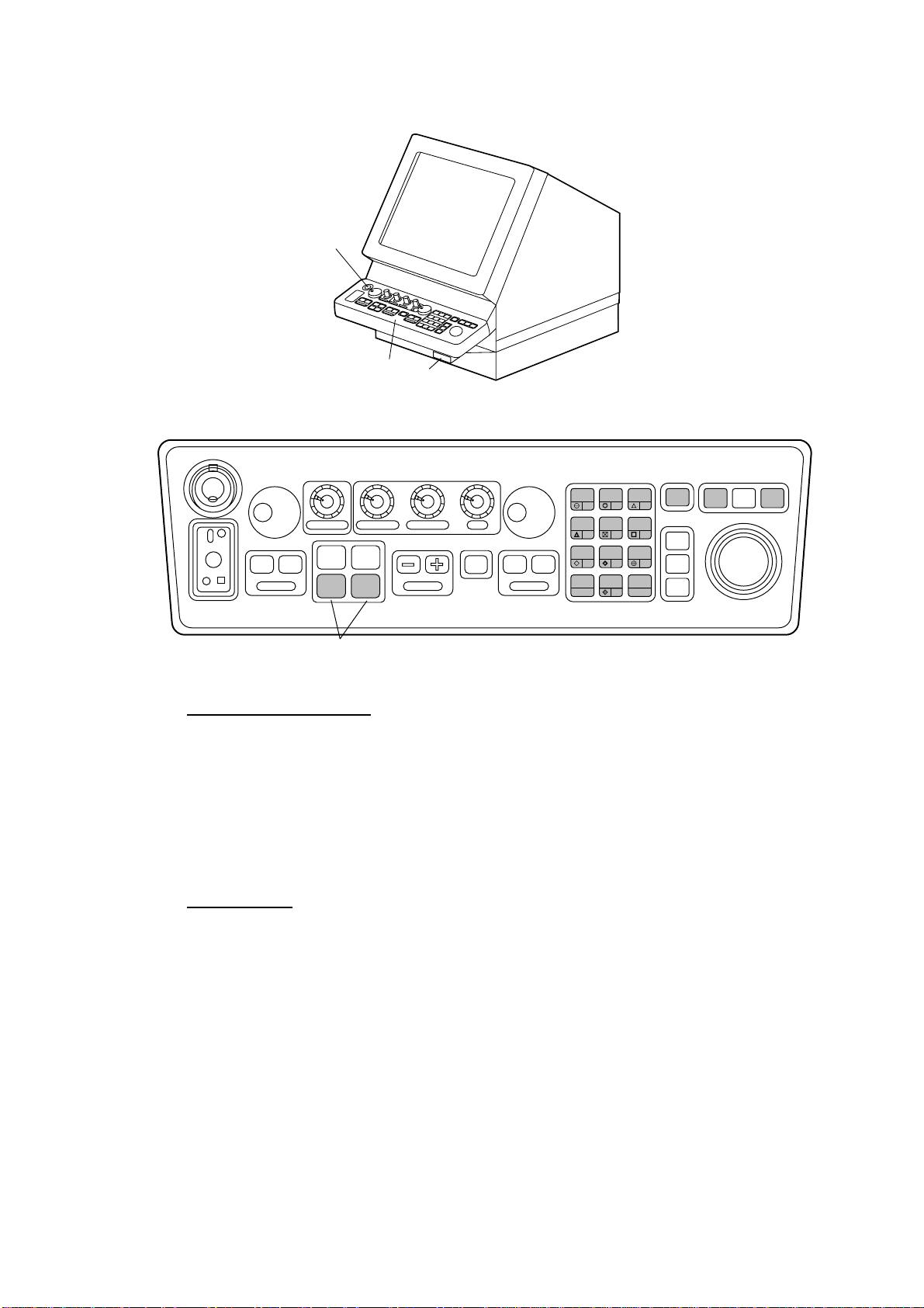
1.2 Controls
Power
switch
Control head
Card
slot
FR-2105 series radar display unit
POWER
ON
OFF
ANTENNA
TUNE
DEGAUSS ERROR
PM
OFF
BRILLIANCE
ON
EBL
#1 #2
AIS
DATA
A/C RAIN
AIS
MENU
A/C SEA
RANGE
GAIN
STBY
OFF
TX
VRM
Function set and labels attached at installation
HL
PANEL
MODE
LOST
TARGET
MARK
A/C
AUTO
ENTER
AUDIO
OFF
3
6
ACQ
TARGET
9
DATA
TARGET
CANCEL
OFF
BRILL
2
1
OFF
VECTOR
CENTER
4
5
CHART
EBL
ALIGN
7
TARGET
TRAILS
CANCEL
CU, TM
RESET
8
0
ON
FR-2105 series control head (RP-250-related controls shaded in gray)
Video plotter controls
RADAR MENU: Open and close the radar menu.
NAV MENU: Open and close the video plotter menu.
CHART ALIGN: Align video plotter display with radar display.
MARK: Enter various marks.
Numeric keys: Enter data.
ENTER: Terminate keyboard input.
AIS controls
RADAR
MENU
PLOT
MENU
NAV
MENU
AIS MENU: Open AIS menu.
AIS DATA: Display basic data for selected target.
AUDIO OFF: Silence AIS-related alarms.
VECTOR: Alternately display true and relative speed and course vector.
LOST TARGET: Erase AIS lost target marks. (ARPA lost target mark is also
erased.)
Note 1: A single beep is produced to signify that the radar has accepted your
command. Two beeps sound in case of incorrect key operation.
Note 2: When the NAV MENU key is pressed in the plotter/radar or plotter
mode, the message “Chart displayed is for reference only. Position
should be confirmed against nautical charts.” appears. Use the
electronic chart as an aid to navigation.
2
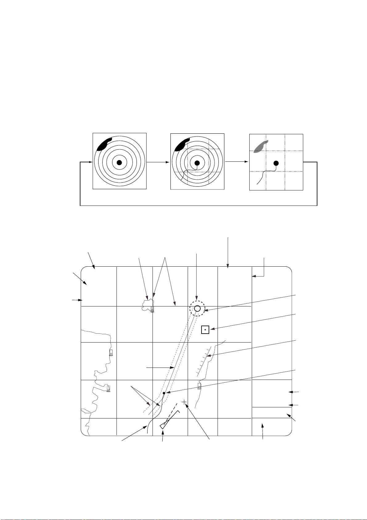
1.3 Choosing Display Mode
1. Press the [RADAR MENU] key.
2. Press the [9] key to choose display mode desired. The illustration at the
bottom of the page shows a sample video plotter display. Note that the
video plotter is not available when SHIP TYPE is set for DEEP SEA.
Note: When the radar display is selected, the display shows the indication
AIS: OFF and when the radar/video plotter display is in use the
indication AIS: ON appears. AIS-related alarms will be released even
if the display shows AIS: OFF, provided the AIS feature is active.
1. OPERATIONAL OVERVIEW
Range and
Bearing
to Cursor
Display
Mode
Radar Display Radar/Video Plotter
Display modes
Range
NM
12
2
/
+
3.458NM
179.9°T
NORTH UP, TM
Coastline
Planned
Route
Nav Line
Grid
011
Arrival
Alarm
Range
10
Video Plotter
Status of AIS function
Show ON to display
AIS symbols.
AIS FUNC: ON
DISP: ON
Data, Menu
Display
POSN [DR] MAN
35°20.370 N
141°18.300 E
+CURSOR MAN
35°20.360 N
141°18.770 E
2002/05/19 13:28 (UTC)
- - AIS ALARM - -
Waypoint
Mark
Prohibited
Area
Own Ship
Marker
Date,
Time
Position
Cursor
Position
Track
AIS Target
Symbol
Cursor
Message Area
(AIS-related
messages.)
Video plotter display
3
1. OPERATIONAL OVERVIEW
About the radar/video plotter display
When using the radar/video plotter display, you may erase marks, lines, grid,
etc. from the display to give priority to the radar display. This is also useful for
brightening charts.
1. Press the [NAV MENU] key to show the VIDEO PLOTTER 1 menu.
2. Press the [7] key to choose PLOTTER PRESENTATION.
3. Press the [7] key again to choose DEFAULT.
4. Press the [ENTER] key.
5. Press the [NAV MENU] key to close the menu.
Note: To restore the normal display, choose USER SET at step 3.
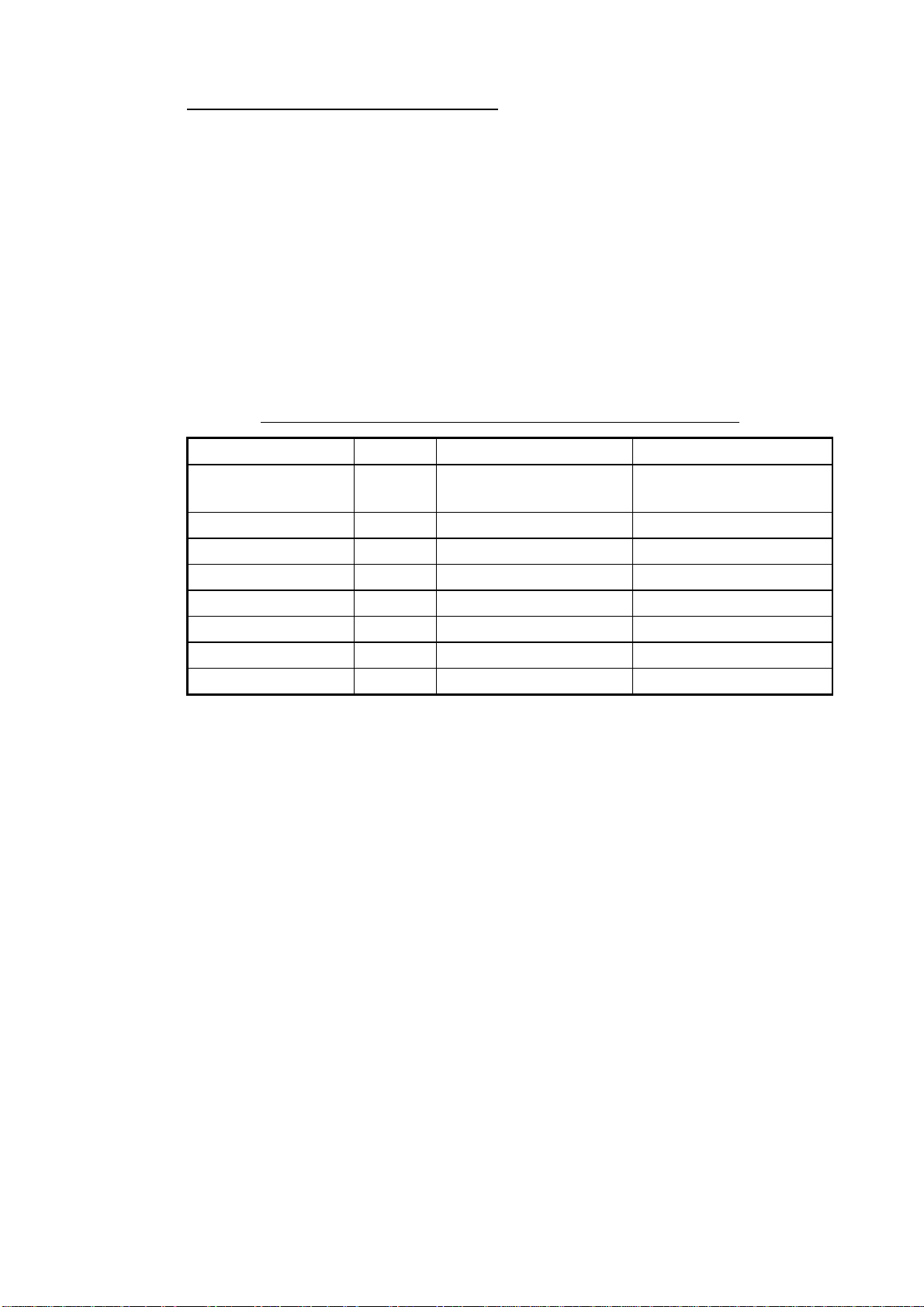
Item and default setting (DEFAULT selected at step 3 above)
Item Setting Item Setting
Lighthouse, wreck ON Background
Coastline ON Echo color Yellow
Land density ON Heading line brilliance Bright
Place name OFF Plotter brilliance MED 2
Mark OFF Range rings brilliance OFF
Own track OFF Chart brilliance MED 1
Other track OFF Symbol brilliance MED 1
Depth contour OFF Grid brilliance OFF
Black (green
characters)
1.4 Choosing Presentation Mode
The RP-250 has five presentation modes: True Motion, North-up, Course-up,
Head-up and Cursor Gyro. You may choose a mode with the [MODE] key.
Note 1: Charts are not available for use in the Head-up and Cursor Gyro
modes.
Note 2: In the true motion mode, the own ship mark is automatically reset to a
point of 75% radius when it is at a distance from the screen center 3/4
the range.
4
1.5 Charts
This section shows you how to display charts and correct their position.
Both the chart card and memory card are susceptible to sunlight. Handle them
carefully, following the guidelines below.
•
Keep them away from direct sunlight and heat sources.
•
Keep cards away from water and chemicals.
•
Keep the connector free of foreign m at erial.
•
Do not drop the cards.
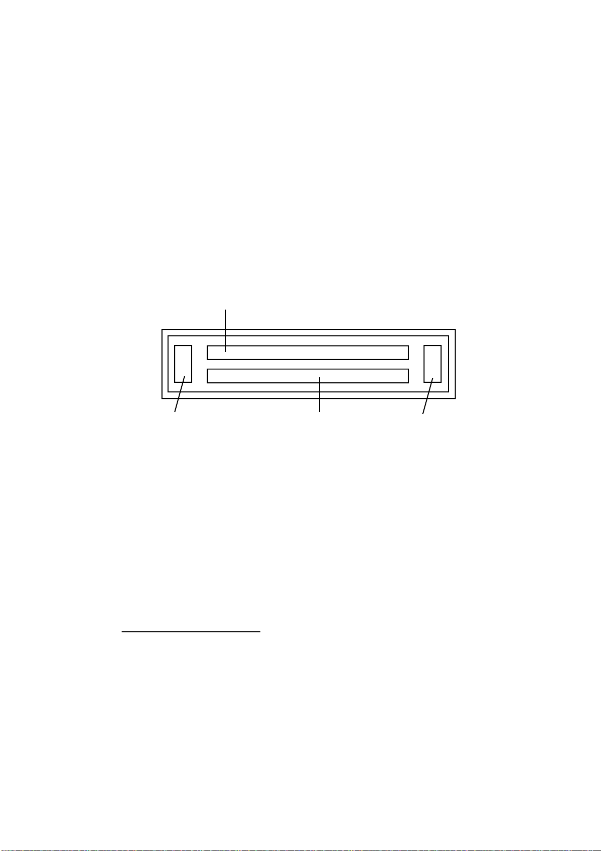
1.5.1 Displaying a chart
To display a chart, do the following:
1. Insert the chart card in the upper slot.
Drive for chart card
1. OPERATIONAL OVERVIEW
Eject button for
lower card
2. Turn on the power switch.
3. After the radar is set in transmit status, choose the video plott er display or
the radar/video plotter display.
To eject a card, press the Eject button and pull out the card.
Note: If a card inserted after the power is turned on, change the range with the
[RANGE] key to display the chart.
Drive for RAM card
Card slots
1.5.2 Chart, cursor position correction
Chart position correction
There may be a case where the radar picture does not mat c h the chart overl ay.
This is due to an error in the position fixing system (GPS, Loran, etc.) or the
different coordinates between the position fixing system and the radar. In this
case, align the chart with the radar image as below. Note that track is neither
recorded nor plotted while chart position is bein g correct ed.
1. Press the [CHART ALIGN] key. M. ALIGNING appears at the top of the
screen.
2. Rotate the trackball to shift the chart (or o wn ship) to the correct position.
3. Press the [CHART ALIGN] key again. MAN AL IGNED appears.
Eject button for
upper card
5

1. OPERATIONAL OVERVIEW
Canceling chart posit ion correction
1. Press the [NAV MENU] and [0] k eys to show the VIDE O PLOTTER 2 menu.
2. Press the [2] k ey to choose NAV DATA POSN.
3. Press the [ E NTER] key t o c anc el correcti on.
4. Press the [ NAV MENU] key to close the menu.
Cursor position correction
The cursor pos ition can be corr ec ted as follows:
1. Press the [ NAV MENU] and [ 0] keys to show the VIDEO PLOTT E R 2 m enu.
2. Press the [ 3] key to choose ALIGN +CURSOR DAT A.
3. Press the [3] key again to choose OFF or ON as appropriate and then
press the [ENTER] key. ON corrects cur s or pos ition and “COR: ON”
appears at t he c ur s or data loc ation (bottom r ight hand side of the screen).
Note: To use AI S c hoos e ON.
4. Press the [ NAV MENU] key to close the menu.
1.6 Setting up the Video Plotter Display
1.6.1 Hiding/Showing graphics
1. Press the [NAV MENU] and [8] k eys to display the PLOT DISPLAY S E LE CT
menu. Current selecti ons appear in reverse video.
Blank items have been turned off on the VIDEO PLOTTER INITIAL
SETTINGS menu. For further detai ls, see paragr aph 6.1.
[PLOTTER DISP SELECT]
1 [VIDEO PLOTTER(1)]
2 DANGER HIGHLIGHT
OFF/ON
3 COAST LINE
OFF/ON
4 LAND DENSITY
OFF/ON
5 PLACE NAME
OFF/ON
6 MARK
OFF/ON
7 OWN SHIP PLOT
OFF/SEPARATE/CONTINUE
8 TARGET PLOT
OFF/ON
9 CONTOUR LINE
OFF/ON
0 GRID
OFF/ L/L
Note 1: For C-MAP chart the following
points differ:
COAST LINE, LAND DENSITY:
Always ON
PLACE NAME:
ON: Displays place name and chart
border line.
CONTOUR LINE:
ON: Displays contour line and spot
soundings.
Note 2: For C-MAP, unit for spot
soundings is fixed for meters and
neither port nor tide info is
available.
PLOTTER DISP S E LE CT menu
2. Press appropriate numeri c k ey twice to hi de or s how graphic as appropriate.
3. Press the [ENTER] key.
4. Repeat steps 2 and 3 to hide or show other graphi c s.
6

5. Press any menu key to close the menu.
1. OPERATIONAL OVERVIEW
Note 1:
LAND DENSITY fills (ON) or hollows (OFF) land on an electronic chart.
Land will be hollow when wrong card or wrong scale is used,
regardless of LAND DENSITY setting.
Note 2:
OWN SHIP PLOT functions as follows:
OFF: Own track is neither plotted nor recorded.
SEPARATE: Own track is neither plotted nor recorded when RECORD
OWN SHIP PLOT of OWN SHIP, TARGET PLOT menu is OFF own
ship plotting.
CONTINUE: Own track is plotted but not recorded when RECORD
OWN SHIP PLOT of OWN SHIP, TARGET PLOT menu is OFF own
ship plotting.
1.6.2 Hiding/Showing nav data
You may choose what navigation data to display on the video plotter display as
follows:
1. Press the [NAV MENU] and [1] keys to display the NAV INFORMATION 1
menu.
[NAV INFORMATION(1)]
1 [VIDEO PLOTTER(1)]
2 SELECT NAVAID
GPS+LC/DEAD RECKONING
/AIS
3 OWN SHIP POSN
OFF/ L/L
4 POSN
00°00.000 N/S
000°00.000 E/W
5 +CURSOR DATA
OFF/L/L
6 WPT DATA
OFF/REL/TRUE
7 [NAV LINE]
8 [WAY POINT]
9 WIND DATA
ON/OFF
0 [NAV INFORMATION(2)]
NAV INFORMATIO N 1 menu
2. Press appropriate numeric key to choose both item and option. Press the
[ENTER] key to register selection.
Note 1: Item 2 chooses source of position data as below.
GPS+LC: Own ship position data fed from GPS or Loran C
navigator.
DEAD RECKONING: Position data entered at item 4 (POSN) is
used as starting point for dead reckoning.
AIS: Own ship position data fed from AIS transponder.
Note 2: When dead reckoning navigation is used on the IMO type radar (G
mode), the AIS feature is automatically turned off, no AIS symbols
are displayed, and the menu item “AIS OFF/ON” is not shown on
the AIS1 menu.
7

1. OPERATIONAL OVERVIEW
For manual input of position (item 4), do the following:
a) Press the [4] key.
b) Enter latitude in six digits with the numeric keys.
c) Press the [ENTER] key. (To change coordinate, press the [4] key and
then press the [ENTER] key).
d) Enter longitude in eight digits.
e) Press the [ENTER] key. (To change coordinate, press the [4] key and
then press the [ENTER] key).
3. Press the [0] key to go to next page, the NAV INFORMATION 2 menu.
Choose options as you did on the NAV INFORMATION 1 menu.
[NAV INFORMATION(2)]
1 [NAV INFORMATION(1)]
2 WIND GRAPH
OFF/ON
3 WIND UNIT
m/s/KT
4 CURRENT DATA
OFF/ON
5 CURRENT GRAPH
OFF/ON
6 DEPTH DATA
OFF/ON
7 DEPTH GRAPH
OFF/ON
8 DEPTH SCALE
10/20/50/100/200/500
9 DEPTH UNIT*
m/ft
0 [NAV INFORMATION(3)]
*= R, G type fishing
mode
NAV INFORMATIO N 2 menu
4. Press the [0] key to display the NAV INFORMATION 3 menu.
[NAV INFORMATION(3)]
1 [NAV INFORMATION(2)]
2 WATER TEMPERATURE*
OFF/ON
3 DATE
OFF/UTC/LOCAL ±00.00H
4 USED WPL#
NAV LINE/WP
5
6
7
8
9
0 [AIS(1)]
*= R, G type fishing
mode
# = USED WPL not shown on G-type
radar.
NAV INFORMATIO N 3 menu
5. To choose time system, press the [3] key several times to choose OFF, UTC
or LOCAL. To use local time, select LOCAL, press [ENTER] twice, and enter
time difference between it and UTC time.
6. Press the [ENTER] key.
7. Press the [NAV MENU] key to close the menu.
8

2 TRACK
This section provides the information necessary f or setting the track display
conditions for own ship and other vessels.
2.1 Stopping Plotting of Own Ship's Track
1. Press the [NAV MENU] and [5] keys.
[OWN SHIP, TARGET PLOT]
1 [VIDEO PLOTTER(1)]
2 RECORD OWN SHIP PLOT
OFF/ON
3 OWN SHIP PLOT INTVL
10/30SEC/1/2/3/6MIN
4 OWN SHIP PLOT COLOR
RED/MAGENTA/YEL*/
GRN*/CYAN/BLU/WHITE*
5 RECORD TARGET PLOT
OFF/ON
6 TARGET PLOT I NTVL
10/30SEC/1/2/3/6MIN
7 [TARGET PLOT COLOR]
8 SMOOTHING
OFF/1/2/3/4/5/6/7/8/9
* = Not available
on IMO type.
OWN SHIP, TARGET PLOT menu
2. Press the [2] key twice to choose OFF.
3. Press the [ENTER] key.
4. Press the [NAV MENU] key to close the menu.
Own ship's track is not plotted. To resume plotting, choose ON at step 2 and
press the [ENTER] key.
2.2 Stopping Plotting of Other Ship’s Track
1. Press the [NAV MENU] and [5] keys.
2. Press the [5] key twice to choose OFF.
3. Press the [ENTER] key.
4. Press the [NAV MENU] key to close the menu. Then, other ship's t r acks are
not plotted.
To resume plotting of other ship’s tracks, choose ON at step 2 and press the
[ENTER] key.
9
2. TRACK
2.3 Track Plotting Interval
The memory stores ship's position in latitude a nd longitude at a sampling rate
set on the OWN SHIP, TARGET PLOT menu. The position data so stored is
used to display past own ship's track on the screen. The memory for own ship
track and other ship track is 20,000 points each. The plotting interval affects
track reconstruction. A shorter interval provides more accurat e reconstruction of
track, however storage time of the track is reduced. A longer inter val stores more
track, however the track is less accurate.
The memory for own ship track is 20,000 points. The table below shows the
relation between plotting interval and maximum recording time. When the
storage capacity is exceeded oldest data is erased to make room of the latest.
Interval Max. Recording Time Interval Max. Recording Time
10 s 55 hrs 30 min 2 min 27 days 18 hr 40 min
30 s 166 hrs 40 min 3 min 41 days 16 hr
1 min 13 days 21 hrs 20 min 6 min 83 days 8 hr
The memory for other ship’s track is 20,000 points for 10 ships. The table
below shows the relation between plott ing interval and maximum recording
time for each ship. Note that the t r ack of ARPA targets 1 thru 10 may be
displayed. The track of ARPA targets 11 thru 30 cannot be displayed.
Interval Max. Recording Time Interval Max. Recording Time
10 s 5 hrs 30 min 2 min 66 hrs 40 min
30 s 16 hrs 40 min 3 min 100 hrs
1 min 33 hrs 21 min 6 min 200 hrs
2.3.1 Choosing track plotting interval
1. Press the [NAV MENU] and [5] keys.
2. To change own ship's track plotting interval, press the [3] key several times to
display desired plotting interval in re verse video. The choices are 10, 30 s; 1,
2, 3, 6 min.
3. Press the [ENTER] key.
4. To change other ship's track plotting interval, press the [6] key several times
to choose plotting interval.
5. Press the [ENTER] key.
6. Press the [NAV MENU] key to close the menu.
2.3.2 Finding track memory used
10
1. Press the [NAV MENU] and [0] keys. Memory used appears as below.
MEMORY IN USE
OWN SHIP = 03456
TARGET = 01124
MARK = 00021
MEMORY IN USE display
2. Press the [NAV MENU] key to close the menu.

2.4 Smoothing
Even when the vessel is sailing in a straight line the track shown on the display
looks irregular. This is due to signal variation of the external navaid. You can
compensate for this irregularity with smoothing.
A smoothing factor between 1 and 9 is available. OFF provides no smoothing. In
most cases a smoothing setting between 1 and 5 is satisfactory.
1. Press the [NAV MENU] and [5] keys.
2. Press the [8] key to choose smoothing factor.
3. Press the [ENTER] key.
4. Press the [NAV MENU] key to close the menu.
2.5 Erasing Track
In busy traffic, the screen may become cluttered. You can remove all or a
percentage of own ship’s track from the memory to clear the display. Tracks of
other ships can also be cleared.
1. Press the [NAV MENU] key and the [9] key to display the PLOTTER ERASE
menu.
[PLOTTER ERASE]
1 [VIDEO PLOTTER(1)]
2 OWN SHIP PLOT
30%/50%/80%/ALL
3 TARGET PLOT
30%/50%/80%/ALL
4 MARK
OFF/ALL
5 WPT
OFF/ALL
6 NAV LINE
OFF/ALL
2. TRACK
PLOTTER ERASE menu
2. Press the [2] key several times to choose OWN SHIP PLOT and the amount
of track you wish to erase.
3. Press the [ENTER] key.
4. To erase other ship's track, press the [3] key several times to choose
TARGET PLOT and the amount of track to erase.
5. Press the [ENTER] key.
6. Press the [NAV MENU] key to close the menu.
11

2. TRACK
2.6 Own Ship Track Color
You may display own ship’s track in red, magenta, yellow*, green*, cyan, blue
or white* as below. (* = Not available on IMO type.)
1. Press the [NAV MENU] key and the [5] key to choose OWN SHIP, TARGET
PLOT.
2. Press the [4] key to choose color desired.
3. Press the [ENTER] key.
4. Press the [NAV MENU] key to close the menu.
2.7 Other Ship Track Color
You may display other ship’s track in red, magenta, yellow*, green*, cyan, blue
or white* as below. (* = Not available on IMO type.)
1. Press the [NAV MENU] key and the [5] key to choose OWN SHIP, TARGET
PLOT.
2. Press the [7] key to choose TARGET PLOT COLOR.
= [TARGET PLOT COLOR] =
1 [OWN SHIP, TARGET PLOT]
2 TARGET NUMBER
01
3 TARGET PLOT COLOR
RED/MAGENTA/YEL/
GRN/CYAN/BLU/WHITE
TARGET PLOT COLOR LIST
TARGET NO. COLOR
01 RED
02 RED
03 RED
04 RED
05 RED
06 RED
07 RED
08 RED
09 RED
10 RED
TARGET PLOT COLOR menu
3. Press the [2] key to choose the target number you want to change the track
color.
4. Key in target number (two digits).
5. Press the [ENTER] key.
6. Press the [3] key to choose color desired.
7. Press the [ENTER] key.
8. Press the [NAV MENU] key to close the menu.
12
3 MARKS, LINES
You can inscribe marks on the display to note im portant points, for example, a
buoy or a wreck. The mark memory capacity is 20,000 points.
3.1 Choosing Method of Entry
Marks can be entered by cursor position, specific lat it ude and longitude or own
ship position.
1. Press the [NAV MENU], [0] and [6] keys.
2. Press the [6] key to choose method of m ark entry; CURSOR, L/L or OWN
SHIP POSN.
3. Press the [ENTER] key.
4. Press the [NAV MENU] key to close the menu.
3.2 Entering Marks/Lines
3.2.1 Entering marks/lines at cursor or own ship position
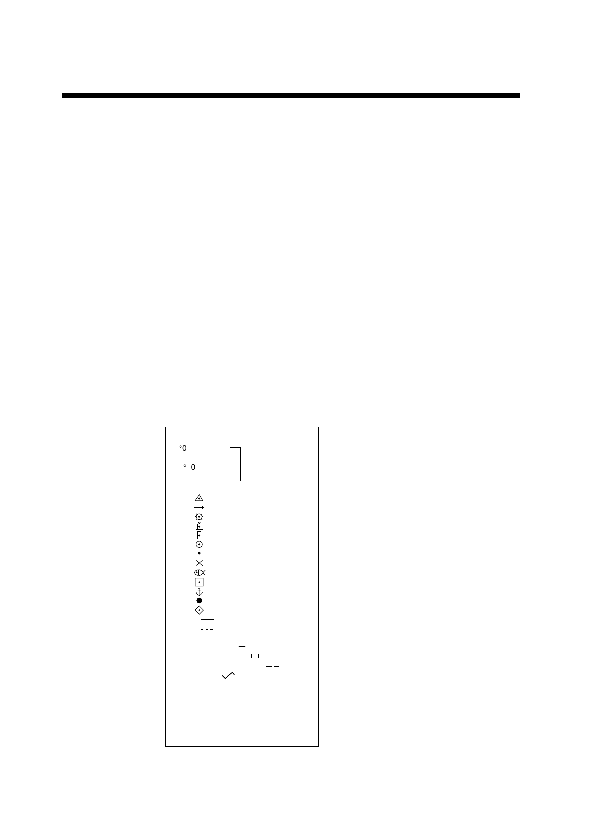
1. Press the [MARK] key to display the ENTER MARK menu.
[ENTER MARK]
00°00. 000 N/S
5-N 6-S
000°00. 000 E/W
7-E 8-W
MARK XX
01
02
03
04
05
06
07
08
09
10
11
12
13
14
15
NAV LINE
16
COAST LINE
17
CONTOUR LINE
18
PROHIBITED AREAS
19
CABLE
20
LINE CHANGE
21
MARK CANCEL
22
MARK COLOR
23
*2
RED/MAGENTA/YEL/
GRN/CYAN/BLU/WHITE
CANCEL ENTER MARK:
CANCEL KEY
1
*
*1 = Shown when mark entry method
is "latitude and longitude."
*2 = Not shown on IMO type.
ENTER MARK menu
13

3. MARKS, LINES
2. For entry at own ship’s position, enter mark number to choose desired
mark, followed by the [ENTER] key. The chosen mark appears at own ship
position.
3. For entry by cursor, operate the trackball to place the cursor on the
position desired for the mark. Enter mark number to choose desired mark
and then press the [ENTER] key. The chosen mark appears at the cursor
position.
4. To inscribe a lin e, first select the mark entry method (see paragraph 3.1)
for “cursor.” Then, do the following:
a) Use the trackball to place the cursor on the starting point of the line.
b) Enter desired line number with the numeric keys and press the [ENTER]
key.
c) Use the trackball to place the cursor on the ending point of the line and
then press the [ENTER] key.
d) Repeat c) to continue drawing the line.
5. To escape the mark entry mode, press the [CANCEL] key.
3.2.2 Entering marks at desired position
1. Press the [MARK] key to open the MARK menu.
2. Enter latitude by the numeric keys and then press the [ENTER] key. To
change polarity, press [5] for North; [6] for South.
3. Enter longitude and then press the [ENTER] key. To change polarity, press
[7] for East; [8] for West.
4. Enter mark number to choose desired mark.
5. Press the [ENTER] key.
6. To escape the mark entry mode, press the [CANCEL] key.
3.2.3 Line change feature
The line change feature allows you to change line type, or to inscribe a separate
line. For example, you may want to quit making nav lines and start making a
coastline.
1. Press the [MARK] key to open the ENTER MARK menu.
2. Inscribe a line as mentioned in paragraph 3.2.1.
3. Press the [2] and [1] keys to choose LINE CHANGE.
4. Enter line no. to be changed.
5. Use the trackball to place the cursor at the beginning of the line and then
press the [ENTER] key.
6. Use the trackball to place the cursor at the end of the line and then press
the [ENTER] key.
7. Repeat step 6 to continue drawing the line.
8. Press the [MARK] key to close the menu.
14

3.3 Mark/Line Color
Not available on IMO type.
1. Press the [MARK] key.
2. Press [2], [3] and [ENTER] key.
3. Continue pressing the [ENTER] to choose desired mark color.
4. Press the [CANCEL] key to close the menu.
Then, marks/lines will be inscribed in the color selected.
3.4 Erasing Marks/Lines
When the mark memory becomes full no marks can entered unless you erase
unnecessary marks.
3.4.1 Erasing individual marks
3. MARKS, LINES
1. Set mark entry method to CURSOR, referring to paragraph 3.1.
2. Press the [MARK] key to open the ENTER MARK menu.
3. Press the [2] key twice to choose MARK CANCEL.
4. Operate the trackball to place t he cursor on the mark you want to erase.
5. Press the [ENTER] key.
6. Press the [CANCEL] key to escape.
3.4.2 Erasing all marks and all lines
1. Press the [NAV MENU] and [9] keys.
2. Press the [4] key twice to choose MARK ALL followed by the [ENTER] key.
3. Press the [NAV MENU] key to close the menu.
3.4.3 Erasing line segments
1. Set mark entry method to CURSOR, referring to paragraph 3.1.
2. Press the [MARK] key to open the mark menu.
3. Press the [2] key twice for MARK CANCEL.
4. Operate the trackball to place t he cursor on the starting point, end point or
intersection of the line you want to erase. Choosing the intersection of two
lines erases both line segments.
5. Press the [ENTER] key.
6. Press the [CANCEL] key to escape.
15

3. MARKS, LINES
3.5 Finding Mark/Line Memory Used
1. Press the [NAV MENU] and [0] keys. Mark memory used appears as below.
MEMORY IN USE
OWN SHIP = 03456
TARGET = 01124
MARK = 00021
MEMORY IN USE display
2. Press the [NAV MENU] key to close the menu.
16
 Loading...