

Page 1
VIDEO PLOTTER
RP-180
Page 2

SAFETY INSTRUCTIONS
WARNING
Be sure to insert the memory card battery correctly.
The battery may explode if it is installed with polarity reversed.
NOTICE
No one navigational aid should be relied upon exclusively for the safety of vessel and
crew. The navigator has the responsibility to check all aids available to confirm his
position. Electronic aids are not a substitute for basic navigational principles and
common sense.
Digital charts cannot replace official nautical charts
Digital charts are intended as an navigational aid. Therefore, position should always be
checked against nautical charts, as well as other aids to navigation.
Handle chart/memory cards carefully
The chart and memory cards are weak against electrostatic discharge. Handle them
with care, observing the following guidelines.
- Keep cards away from heat sources.
- Replace cards in their protective cases after use.
Replace memory card battery within 10 minutes of removal.
Replace the memory card battery within 10 minutes of removal to prevent loss of
data.
i
Page 3

TABLE OF CONTENTS
FOREWORD ..................................................................................................................iv
1. OPERATIONAL OVERVIEW .............................................................................. 1-1
1.1 Introduction ..................................................................................................................... 1-1
1.2 Controls Used By the Video Plotter, AIS ........................................................................1-2
1.3 Choosing Displays.......................................................................................................... 1-3
1.4 Choosing Presentation Mode .........................................................................................1-4
1.5 Shifting the Display......................................................................................................... 1-5
1.6 Choosing Chart Scale..................................................................................................... 1-6
2. CHART CARDS.................................................................................................. 2-1
2.1 Displaying Charts ........................................................................................................... 2-1
2.2 Showing/Hiding Chart Features .....................................................................................2-3
2.3 Position, Bearing Correction........................................................................................... 2-5
3. TRACK................................................................................................................ 3-1
3.1 Displaying Own Ship’s Track.......................................................................................... 3-1
3.2 Stopping Plotting of Own Ship’s Track ...........................................................................3-2
3.3 Changing Own Ship’s Plot Interval................................................................................. 3-3
3.4 Other Ship’s Tracks and Plotting Interval ....................................................................... 3-4
3.5 Erasing Own Ship’s Track, Other Ship’s Track .............................................................. 3-5
3.6 Own Ship, Target Track Color ........................................................................................ 3-6
4. MARKS, LINES .................................................................................................. 4-1
4.1 Displaying Marks, Lines ................................................................................................. 4-1
4.2 Entering Marks, Lines..................................................................................................... 4-3
4.3 Erasing Marks, Lines...................................................................................................... 4-5
4.4 MOB Mark....................................................................................................................... 4-6
4.5 Origin Mark .....................................................................................................................4-7
4.6 Mark Color ......................................................................................................................4-7
5. WAYPOINTS, ROUTES...................................................................................... 5-1
5.1 Turning Waypoints On/Off ..............................................................................................5-1
5.2 Entering Waypoints......................................................................................................... 5-1
5.3 Waypoints .......................................................................................................................5-3
5.4 Creating Routes.............................................................................................................. 5-4
5.5 Turning Route Display On/Off ........................................................................................ 5-7
5.6 Deleting Route Waypoints .............................................................................................. 5-8
5.7 Deleting Routes .............................................................................................................. 5-8
6. NAVIGATION...................................................................................................... 6-1
6.1 Navigation....................................................................................................................... 6-1
6.2 Cancelling Navigation..................................................................................................... 6-4
6.3 Skipping Route Waypoints ............................................................................................. 6-4
7. ALARMS............................................................................................................. 7-1
7.1 Arrival Alarm, Anchor Watch Alarm ................................................................................ 7-1
7.2 XTE Alarm, Border Alarm ............................................................................................... 7-3
ii
Page 4

8. MEMORY CARD OPERATIONS......................................................................... 8-1
8.1 Formatting Memory Cards.............................................................................................. 8-1
8.2 Saving Screen Contents to Memory Card...................................................................... 8-3
8.3
Displaying Memory Card Contents on the Display
8.4 Playing Back Memory Cards.......................................................................................... 8-6
8.5 Erasing Files from Memory Cards.................................................................................. 8-7
............................................................. 8-5
9. OTHER FUNCTIONS.......................................................................................... 9-1
9.1 Entering Ship’s Position Manually .................................................................................. 9-1
9.2 Smoothing.......................................................................................................................9-2
9.3 Viewing Chart Card Contents......................................................................................... 9-2
9.4 Adjusting Brilliance ......................................................................................................... 9-3
9.5 Clearing All Data............................................................................................................. 9-4
9.6 Restoring Default Settings.............................................................................................. 9-4
9.7 Marker Colors on Chart Cards .......................................................................................9-5
9.8 Apportioning the Memory ............................................................................................... 9-6
10. AIS.................................................................................................................... 10-1
10.1 Changing Function of [F2] Key to AIS ........................................................................ 10-1
10.2 Turning AIS Feature On/Off ........................................................................................ 10-2
10.3 Activating Targets........................................................................................................ 10-3
10.4 Sleeping Targets .........................................................................................................10-4
10.5 Displaying Target Data................................................................................................ 10-5
10.6 Lost Target ..................................................................................................................10-7
10.7 Messages.................................................................................................................... 10-7
10.8 History Display ............................................................................................................ 10-9
10.9 AIS Symbol Color...................................................................................................... 10-10
10.10 Automatic Target Activation ...................................................................................... 10-11
10.11 Lost Target Range..................................................................................................... 10-11
10.12 ROT Display Setting ................................................................................................. 10-12
10.13 Combining AIS with ARPA (fusion) ........................................................................... 10-13
10.14 AIS System Messages.............................................................................................. 10-14
10.15 AIS Alarm Message .................................................................................................. 10-16
11. MAINTENANCE, TROUBLESHOOTING ..........................................................11-1
11.1 Replacement of Batteries ........................................................................................... 11-1
11.2 Diagnostic Test............................................................................................................ 11-2
12. INSTALLATION ................................................................................................ 12-1
12.1 Necessary Parts.......................................................................................................... 12-1
12.2 Installation................................................................................................................... 12-1
APPENDIX................................................................................................................AP-1
1. Digital Interface.................................................................................................................. AP-1
2. Interface Function .............................................................................................................. AP-4
3. Main Board Modification (IEC 60936-1 related items) ...................................................... AP-4
4. Menu Tree.......................................................................................................................... AP-5
5. Chart Icons ........................................................................................................................ AP-9
SPECIFICATIONS.....................................................................................................SP-1
INDEX.........................................................................................................................IN-1
iii
Page 5

v
FOREWORD
A Word to RP-180 Owners
Congratulations on your choice of the FURUNO RP-180 Video Plotter. We are confident
you will see why the FURUNO name has become synonymous with quality and reliability.
For nearly 50 years FURUNO Electric Company has enjoyed an enviable reputation for
innovative and dependable marine electronics equipment. This dedication to excellence is
furthered by our extensive global network of agents and dealers.
Your RP-180 is designed and constructed to meet the rigorous demands of the marine
environment. However, no machine can perform its intended function unless installed,
operated and maintained properly. Please carefully read and follow the recommended
procedures for operation and maintenance.
We would appreciate hearing from you, the end-user, about whether we are achieving our
purposes.
Thank you for considering and purchasing FURUNO equipment.
Features
The Video Plotter RP-180 is an optional circuit board which is accommodated in the display
unit of the FR-1500 MARK-3 series radars, and provides video plotter functions, such as
waypoint marking and route creation, and AIS (optional).
The main features are
•
Chart overlay on radar display
•
Head-up display for chart card data
•
Memory cards for unlimited storage of data
•
Memory cards useable together with chart cards
•
Radar position correction
•
Alarms: Arrival, Anchor Watch, Border, XTE (Cross-Track Error)
•
AIS function available with connection of AIS transponder
•
Own ship’s and other ships tracks available in various colors
i
Page 6

1.
OPERATIONAL OVERVIEW
1.1 Introduction
The Video Plotter RP-180 is an optional circuit board (RP board) which is accommodated in
the display unit of the FR-1500 MK3 series radar. It permits use of two memory cards, a
memory card (RAM card) for storing own ship and other ship tracks and marks, and the
other is a chart card (ROM card) for digital charts.
With connection of an AIS (Universal Automatic Identification System) transponder to the
RP board, the RP-180 provides navigation data about vessels which carry an AIS
transponder.
10 navigation lines may be stored and each line may contain up to 30 waypoints. 100
waypoints are available. The user may enter position data in waypoints 01-98. (Waypoint 00
is for own ship position when destination is set; waypoint 99 is for waypoint from external
equipment.) Own ship and other ship tracks may be stored at a selected interval.
Charts are superimposed on the radar picture without disturbing the radar observation. The
chart area is dependent on the radar range in use. The RP-180 comes in two versions
according to chart to be used: FURUNO/NAVIONICS and FURUNO/C-MAP.
1-1
Page 7
1. OPERATIONAL OVERVIEW
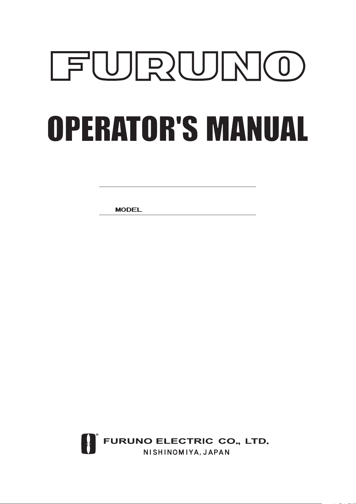
1.2 Controls Used By the Video Plotter, AIS
MODE
1
TGT
2
TRAIL
TGT
3
ALARM
SHIFT
4
ZOOM
INDEX
5
LINE
EBL
6
OFFSET
PLOT
Card Slot
7
SYMBOL
8
MARK
F 19
F 20
MENU
CANCEL
CLEAR
ENTER
SELECT
TX
STBY
POWER
ON
OFF
EBL
DEGAUSS (PUSH)
POWER Switch
BRILL
ONOFF
BKGND
DIMMER
COLOR
A/C RAIN
TLL (PUSH)DAY/NIGHT (PUSH)
AUDIO
OFF
RINGS
A/C SEA
A/C AUTO (PUSH)
FUNCT
ION
GAIN
HL OFF (PUSH)
RANGE
ONOFF
VRM
Controls used by the video plotter
MODE: Chooses presentation mode.
SHIFT/ZOOM: Offcenters the display (momentary press); zoom feature (long press).
MARK: Inscribes mark.
Numeric keys: Enter alphanumeric data.
AUDIO OFF: Silences audible alarm.
MENU: Opens/closes the menu.
CANCEL/CLEAR: Clears entire line of data; erases marks, cancels selection.
ENTER/SELECT: Registers data.
HL OFF: Temporarily erase the RP screen.
RANGE: Chooses radar range.
Controls used by the AIS
F2: Opens AIS menu.
CANCEL/CLEAR: Erases lost target.
ENTER/SELECT: Displays data for the target selected.
AUDIO OFF: Silences AIS-related audible alarm.
1-2
Page 8
1. OPERATIONAL OVERVIEW
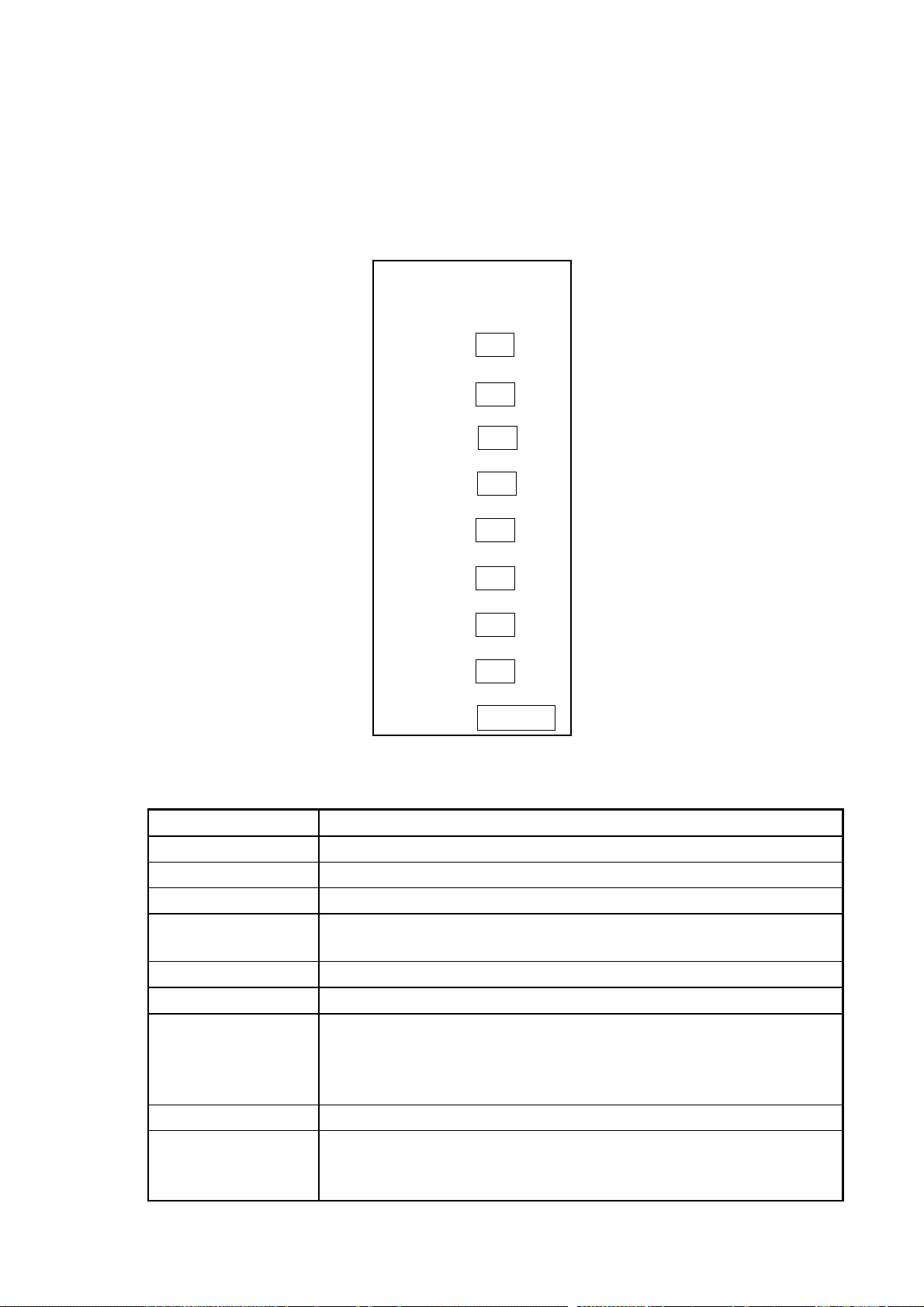
1.3 Choosing Displays
The RP-180 has three displays: Radar, Video Plotter, and Combination (radar + video
plotter). Displays may be selected on the Video Plot/AIS menu as follows:
1. Press the [MENU] key.
2. Press the [1] key twice to show the VIDEO PLOT/AIS menu.
VIDEO PLOT/AIS MENU
1. Radar Disp
2. Combination Disp
3. Video Plot Disp
4. Waypoint
5. Route
6. Destination Set
7. Plot Interval
8. Memory Card
Coastline/Mark Disp
9.
0.
AIS/Miscellaneous1
VIDEO PLOT/AIS menu
3. Press the [1], [2] or [3] key to choose the mode desired.
4. Press the [MENU] key to close the menu.
Video Plotter DisplayCombnation DisplayRadar Display
Displays
Note 1: The combination display requires heading signal. When the heading signal fails,
the radar display is automatically selected.
Note 2: The RP-180 may be used with the IMO-specification radar, however the video
plotter display is not available.
1-3
Page 9
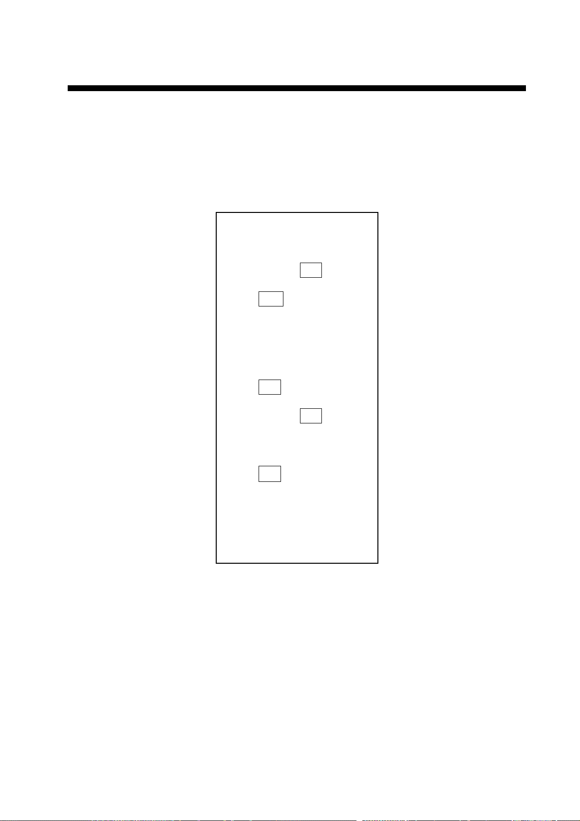
1. OPERATIONAL OVERVIEW
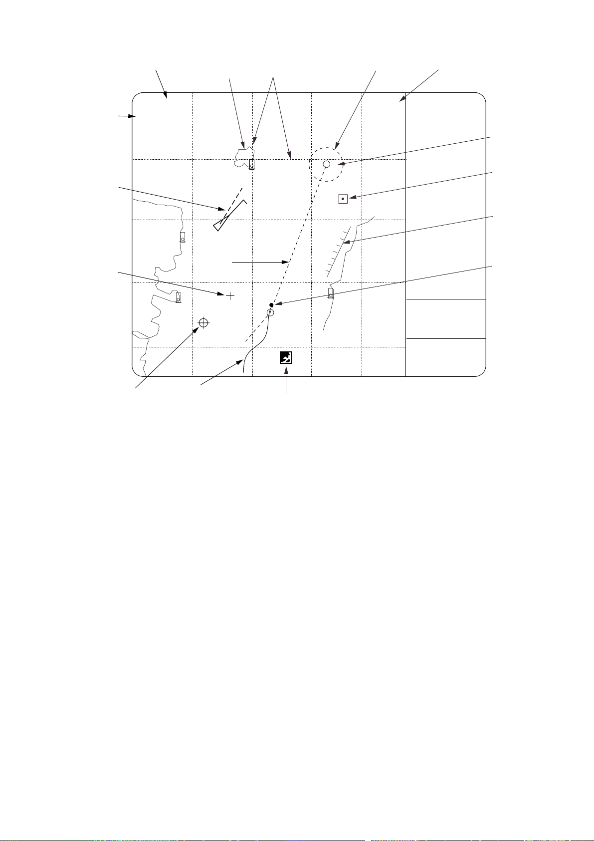
Display Mode
AIS Active
Target
Cursor
Range
12NM
HU RM
Coastline
Route
Grid
Alarm Range
AIS: D
10
11
AIS function
set for "DISP".
Data, menu
display area
Waypoint
Marker
Mark
Prohibited
Area
Own Ship
Marker
Error Message
Location
Origin Mark
Own Ship’s
Track
Icon
1.4 Choosing Presentation Mode
Five presentation modes are available by the [MODE] key: head-up, head-up true bearing,
course-up, north-up, and true-motion. (North-up, head-up true bearing, course-up and true
motion require a heading signal. TM mode additionally requires a speed signal.) Each time
the key is pressed, if heading is input to the radar, the display and the display mode
indication at the top left corner of the display change in the sequence of HU, HU TB, CU,
NU and TM. If there is no heading signal input, the display mode is always HU.
1-4
Page 10

1. OPERATIONAL OVERVIEW
1.5 Shifting the Display
1.5.1 Shifting by the trackball
The display can be shifted by the trackball up to 75% of the range in use in any direction.
Operate the trackball to shift the display, and the display shifts in the direction the trackball
is operated. When the cursor reaches an edge of the display, the pictures shifts in the
opposite direction.
1.5.2 Offcenter
Own ship position, or sweep origin, can be displaced to expand the view field without
switching to a larger range scale. The sweep origin can be offcentered to a point specified
by the cursor, up to 75% (50% in the true motion mode) of the range in use in any direction.
This feature is not available on the 72 nm range or higher.
To offcenter the radar picture:
1. Place the cursor at a position where you wish to move the sweep origin by operating the
trackball.
2. Press the [SHIFT/ZOOM] key momentarily. Then, the sweep origin is offcentered to the
cursor position. However, the heading line is left in the same position.
3. To cancel offcentering, press the [SHIFT/ZOOM] key again.
1.5.3 Zoom
Zoom enlarges an area of interest as large as twice the normal viewing. This feature is
available on the IMO-type radar only.
1. Place the cursor (+) close to the point of interest by operating the trackball.
2. Press and hold down the [SHIFT/ZOOM] key for about two seconds. The area around
the cursor and own ship is enlarged twice as large as the original size.
3. To cancel zoom, press and hold down the [SHIFT/ZOOM] key about two seconds.
Note: The zoom feature is inoperative when the display is off centered.
1-5
Page 11

1. OPERATIONAL OVERVIEW
1.6 Choosing Chart Scale
The chart scale can be selected with the [RANGE+] and [RANGE-] key. A larger range
shrinks the picture; a smaller one enlarges it.
1-6
Page 12
2.
CHART CARDS
NOTICE
Chart cards are intended as an aid to
navigation. The navigator has the
responsibility to check all aids
available to confirm position.
Handle chart cards and memory cards
with care.
- Keep cards away from direct sunlight,
heat sources, and active gases.
- Keep cards away from water and
chemicals.
- Keep the connector free of foreign
material.
- Do not drop the cards.
2.1 Displaying Charts
2.1.1 Inserting chart cards
1. Open the card slot cover at the left hand side of the display.
2. Insert a chart card label side left, arrow forward in the left-side card slot.
COASTLINE DATA CARD
FURUNO ELECTRIC CO., LTD.
Chart card
3. Close the card slot cover.
4. Choose the combination display or the video plotter display.
5. Press the [+] or [-] key to display the chart.
Note: Chart cards may be inserted in the left slot; memory card in the right slot.
2-1
Page 13

2. CHART CARDS
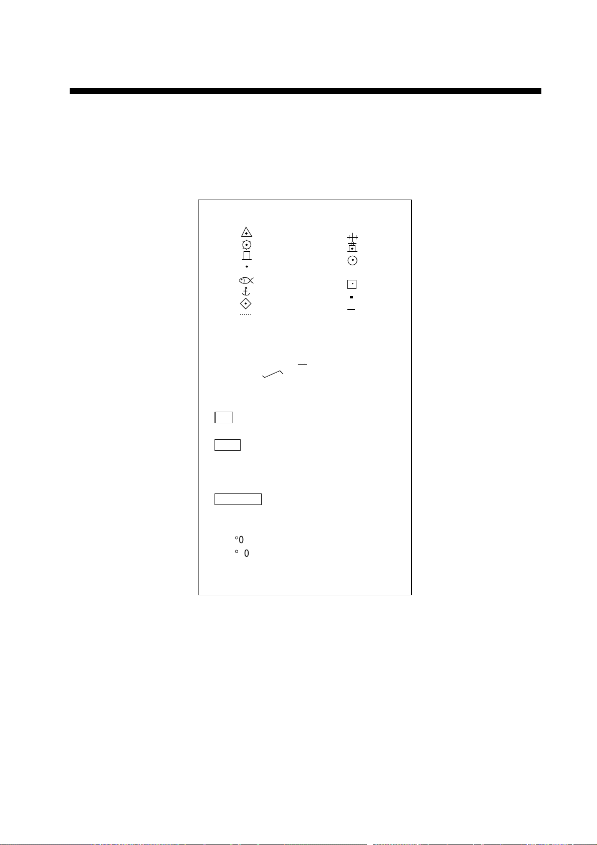
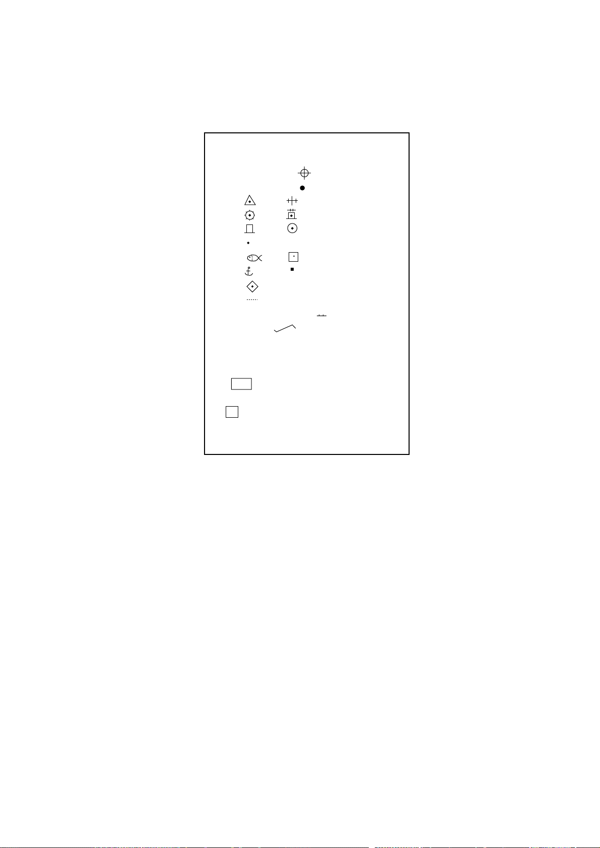
2.1.2 Chart icons
Chart icons are displayed to alert you to chart status.
Chart properly
displayed.
Chart
overenlarged.
Chart overenlarged
or wrong chart.
Chart icons
2.1.3 Ejecting chart cards
Chart cards may be ejected with the radar turned on or off.
1. Press the EJECT button on the card slot.
3. Remove the chart card.
2.1.4 Troubleshooting
•
Card inserted but no chart appears.
•
Small island, etc. not filled in.
•
Card is removed but chart remains on the screen.
To rectify the above cases, press the [+] or [-] key.
2-2
Page 14
2.2 Showing/Hiding Chart Features
Chart features may be turned on/off as follows:
1. Press the [MENU] key to display the main menu.
2. Press the [1] key twice to show the Video Plot/AIS menu.
3. Press the [9] key twice to choose Coastline/Mark Disp.
Coastline/Mark Disp
1. ↑
2. Waypoint
Off On
3. Grid
Off On
4. Coast Line
Off On
5. Land Density
Off On
6. Place Name
Off On
7. Lighthouse
Off On
8. Lighthouse Data
Off On
9. Depth Contour
Off On
0. Plotter Presentation
Default User set
2. CHART CARDS
Coastline/Mark Disp menu
Press appropriate numeric key to choose both item and option.
4.
Item Description
Waypoint Turns waypoint display on/off.
Grid Turns grid on/off.
Coastline Turns coastline on/off.
Land Density Fills in (On) or hollows (Off) land. Note that land will be hollow if the
wrong chart scale is used regardless of this setting.
Place Name Turns geographic names on/off.
Lighthouse Turns lighthouse icons on/off.
Lighthouse Data Turns lighthouse viewing angle on/off. Viewing angle is shown as an
arc extending from lighthouse position. Arc color, white or green, is the
color of the lighthouse’s beam. This feature is available on selected
charts.
Depth Contour Turns depth contour lines on/off.
Plotter Presentation Chooses plotter screen settings; default or user setting. Default
settings are as shown on the next page. Choose Default to erase
marks, lines, L/L grid, etc., giving priority to the radar display.
2-3
Page 15

2. CHART CARDS
5. Press the [ENTER/SELECT] key to register your selection.
6. Press the [MENU] key to escape.
metIgnitteS
dnaecnaillirb,srolocradaR
dnuorgkcab
rolocdnuorgkcaBkcalB
rolocohcEwolleY
stnemeletrahcforoloC
dnaL Green
dirG Green
skraM Green
ruotnoC Green
noitamrofnitrahC
stniopyaWNO
dirGFFO
eniltsaoCNO
ytisneddnaLNO
emanecalPFFO
esuohthgiLNO
atadesuohthgiLNO
ruotnochtpeDFFO
kcarttegraTFFO
kcartSOFFO
skraMFFO
2-4
Page 16

2. CHART CARDS
2.3 Position, Bearing Correction
2.3.1 Position correction
There may be some instances where the chart is not overlaid on the radar picture correctly.
You can compensate for this error by applying an offset to chart position.
Note 1: A gyrocompass is required to get accurate correction.
Note 2: The radar display and coastline data use different calculation methods, thus they
do not agree. Error is most prevalent in high longitudes.
1. Press the [MENU] key to open the main menu.
2. Press the [8] key twice to choose Mark.
3. Press the [5] key twice to choose Position Correction.
Position Correction
1. ↑
2. Position Corr.
No Yes
3. Delta L/L Entry
Delta L/L
00.000'S
00.000'W
Position Correction menu
4. Press the [2] key to choose Yes, and press the [ENTER/SELECT] key.
5. Press the [ENTER/SELECT] key.
6. Press the [3] key to choose Delta L/L Entry.
7. Press the [ENTER/SELECT] key. The menu disappears and you are asked to operate
the trackball to shift the chart.
8. Operate the trackball to shift the chart so that it is correctly aligned with the radar
picture.
9. Press the [ENTER/SELECT] key.
10. Press the [MENU] key. The offset icon (
To remove the offset, choose No at step 4 in the above procedure.
) appears at the bottom of the display.
2-5
Page 17

2. CHART CARDS
2.3.2 Bearing correction
In some cases radar bearing may not match chart bearing. This can be corrected by
offsetting bearing, automatically or manually. This feature is useful when no coastline is
displayed; that is, vessel is in mid ocean. A magnetic compass is required.
1. Press [MENU], [8], [8], [5], [5] to display the Position Correction menu.
2. Press the [4] key to choose Manu., and press the [ENTER/SELECT] key.
3. Press the [5] key to choose Manual Entry, and press the [ENTER/SELECT] key. The
menu disappears and the prompt “Rotate chart data by using VRM/EBL knob, and press
ENT.” appears.
4. As the prompt says, use the EBL or VRM knob to rotate chart data.
5. Press the [ENTER/SELECT] key. Control is returned to the Position Correction menu.
6. Press the [MENU] key to close the menu. The offset icon (
the display.
To remove the bearing offset, choose Off at step 2 in the above procedure.
) appears at the bottom of
2-6
Page 18
3.
TRACK
3.1 Displaying Own Ship’s Track
Own ship’s track may be displayed as follows:
1. Press the [MENU] key.
2. Press the [1] key twice to show the Video Plot/AIS menu.
3. Press the [7] key twice to choose Plot Interval.
Plot Interval
1. ↑
2. Own Track
Off On
3. Plot Mode
Time Dist
4. Plot Time
Time = 00M30S
5. Plot Distance
Dist = 0.02nm
6. Save Own Track
Yes No
7. Other Track*
Off On
8. Set Other Plot Intvl*
Time = 00M30S
9. Save Other Track*
Yes No
0. Plot Color
* Function available with ARP-17.
Plot Interval menu
4. Press the [2] key to choose On from the Own Track field.
5. Press the [ENTER/SELECT] key to register your selection and the [MENU] key to close
the menu.
3-1
Page 19
3. TRACK
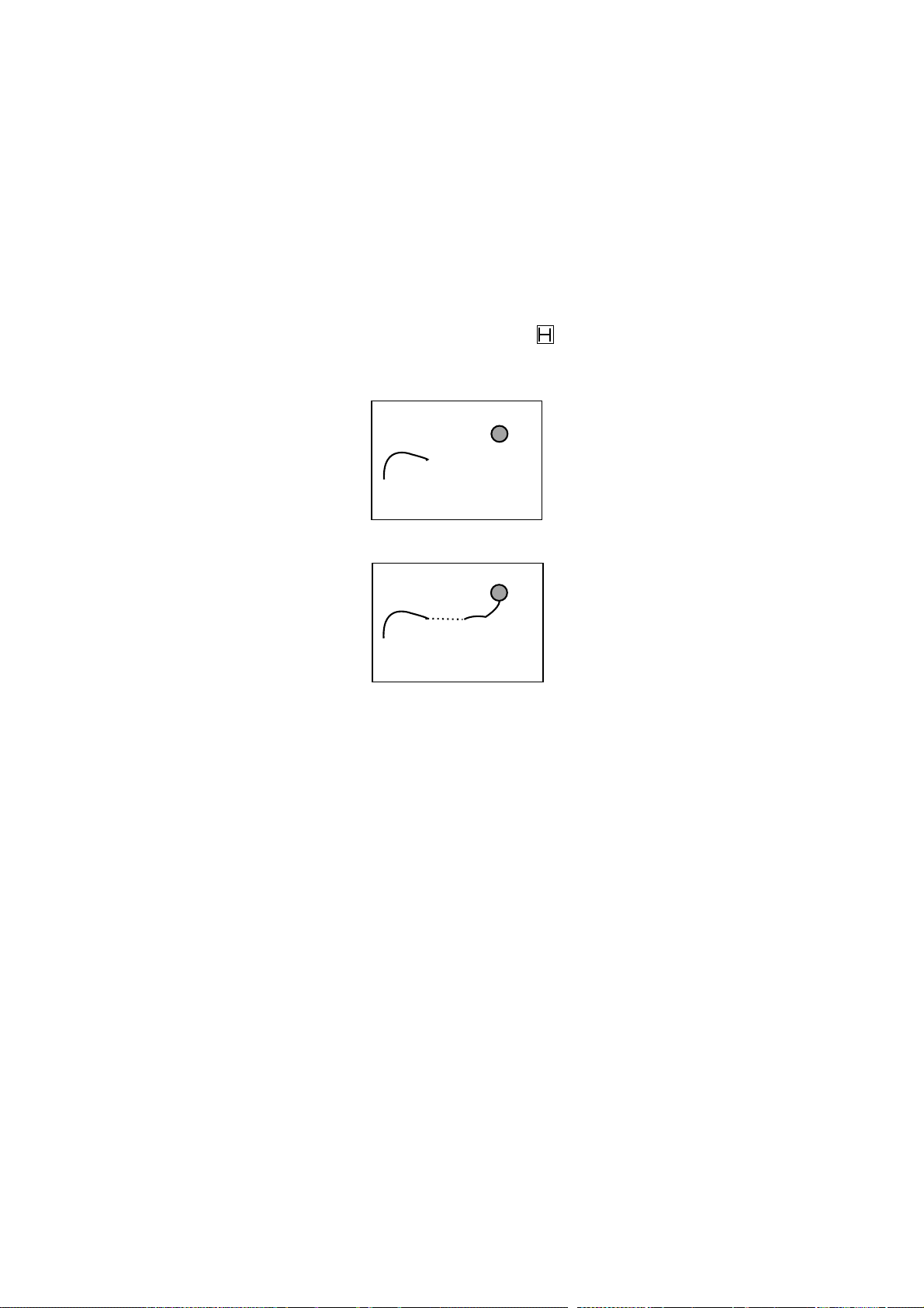
3.2 Stopping Plotting of Own Ship’s Track
When your ship is at anchor or returning to port you probably will not need to plot (record)
the track. You can stop plotting the track, to conserve the track memory, by actuating the
“HOLD” function. The track is neither plotted nor saved, thereby conserving the track
memory.
3.2.1 Stopping track plotting
1. Press [MENU], [1], [1], [7], [7] to display the Plot Interval menu.
2. Press the [6] key to choose No from the Save Own Track field.
3. Press the [ENTER/SELECT] key. The HOLD icon (
screen. (Video Plotter display only.)
4. Press the [MENU] key to finish.
Plotting
stopped
) appears at the bottom of the
(a) Plotting stopped; track is not plotted
Plotting
resumed
(b) Track is again plotted when plotting
is resumed.
Track plotting stopped, track plotting resumed
To resume plotting, choose Yes at step 2 in the above procedure.
3-2
Page 20

3. TRACK
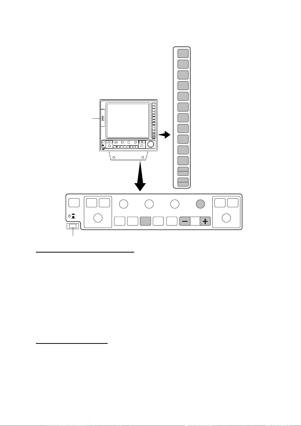
3.3 Changing Own Ship’s Plot Interval
The plot interval determines both how the track will be reconstructed on the display and the
track storage time.
3.3.1 How the track is drawn
The “quality” of the track displayed largely depends on the plot interval setting, smoothing
rate, etc.
In drawing the track, first the ship’s position fed from the navigation aid is stored into the
radar’s memory at an interval of time or distance selected by the operator. This interval of
time or distance is called the “Plot Interval” and it is selected considering the ship’s speed,
the chart scale, etc. If a shorter interval is selected, a reconstructed course line is provided
with better accuracy, but total storage time of the track is reduced.
Obviously there is a trade off between smooth reconstruction of the track and plot storage
time: The shorter the interval the smoother the reconstruction but storage time is reduced.
The following figure compares plot interval and track reconstruction.
: Actual track : Displayed track
(a) Small plotting interval (b) Large plotting interval
Plotting interval and
how track is plotted
3.3.2 Plot interval by time or distance
The plot interval can be selected by “Time” or “Distance”. “Distance” is useful when the ship
is anchored, since track is not plotted while the vessel is stationary.
3.3.3 Setting plot interval
1. Press [MENU], [1], [1], [7], [7] to display the Plot Interval menu.
2. Press the [3] key to choose Time or Dist from the Plot Mode field.
3. Press the [ENTER/SELECT] key.
4. Press the [4] key if you selected Time at step 2; [5] key if you selected Dist.
5. Key in plotting interval with the numeric keys.
6. Press the [ENTER/SELECT] key to register your selection and the [MENU] key to close
the menu.
3-3
Page 21

3. TRACK
3.4 Other Ship’s Tracks and Plotting Interval
The tracks of up to 20 ships may be displayed when the Auto Tracking Aid ARP-17 is
interfaced with the radar.
The plotting interval for other ships tracks can be set independently of that for own ship.
Also, plotting of other ships tracks may be suspended to conserve track memory.
1. Press [MENU], [1], [1], [7], [7] to display the Plot Interval menu.
2. Press the [7] key twice to choose On from Other Track.
3. Press the [ENTER/SELECT] key followed by the [MENU] key.
3-4
Page 22
3. TRACK
3.5 Erasing Own Ship’s Track, Other Ship’s Track
3.5.1 Erasing track by percentage
You may erase own ship’s track and other ship’s track by percentage points as follows:
1. Press the [MENU] key.
2. Press the [1] key twice to show the Video Plot/AIS menu.
3. Press the [0] key twice to choose AIS/Miscellaneous1.
4. Press the [3] key twice to display the Delete Memory menu.
Delete Memory
1. ↑
2. Mark
No
Display
All
3. Own Track
No
30%
50%
80%
All
4. Target Track
No
30%
50%
80%
All
5. Own Track Color All
R Y* G* C
M B W*
6. Target Track Color All
R Y* G* C
M B W*
Mark in use
3/20000
Own Track in use
17/20000
Target Track in use
0/20000
* Not available on IMO-type radar.
Delete memory menu
5. Press the [3] key (Own Track) or [4] key (Target Track) to choose amount of track to
erase. For example, 30% erases 30% of the track points stored in the track memory.
6. Press the [ENTER/SELECT] key.
7. Press the [ENTER/SELECT] key again followed by the [MENU] key.
3-5
Page 23

3. TRACK
3.5.2 Erasing track by color
Own ship’s track and target tracks may be erased by color as follows:
1. Press [MENU], [1], [1], [0], [0], [3], [3] to show the Delete Memory menu.
2. Press the [5] key (Own Track Color All) or [6] (Target Track Color All) depending on your
objective.
3. Press the [ENTER/SELECT] key.
4. Press the [ENTER/SELECT] key again followed by the [MENU] key.
3.6 Own Ship, Target Track Color
You may display own ship’s track and target tracks in red, yellow*, green*, cyan, magenta,
blue or white*. as below. (* = Not available on IMO-type radar.) The color currently chosen
for each target is shown on the Plot Color menu.
1. Press the [MENU] key [1], [1], [7], [7] to open the Plot Interval menu.
2. Press the [0] key twice to choose Plot Color.
Plot Color
1.
2. Own Ship Color
R Y* G* C
M B W*
3. Target No. 01
4. Target Plot Color
R Y* G* C
M B W*
[Target Plot Color List]
Target No. Color
01 M
02 M
03 M
.
.
.
20 M
*: Not available on IMO-type radar.
Plot color menu
3. Do one of the following depending on your objective:
Own Ship Track Color
a) Press the [2] key to choose Own Ship Color
b) Press the [2] key again to choose color desired.
Target Track Color
a) Press the [3] key to choose Target No.
b) Key in target no. with the numeric keys and then press the [ENTER/SELECT] key.
c) Press the [4] key to choose Target Plot Color.
d) Press the [4] key again to choose color desired.
4. Press the [ENTER/SELECT] key.
5. Press the [MENU] key to close the menu.
3-6
Page 24
4.
MARKS, LINES
4.1 Displaying Marks, Lines
4.1.1 Displaying marks, lines on the radar display
1. Press the [MENU] key.
2. Press the [8] key twice to show the Mark menu.
1. Mark Selection = 01
01
03
05
07
09
11
13
15
16 Nav Line --17 Coastline __
18 Depth Contour --19 Prohibited Area
20 Cable
21 Erase Mark
2. Display
On Off
3. Erase
No
Erase Display
Erase All
4. Entry Method
Cursor
L/L
OS Position
°
00
000
5. Position Correction
Mark in use 7/3000
00.000’N
°
00.000’E
02
04
06
08 X
10
12
14
Mark menu, radar display
3. Press the [2] key to choose On.
4. Press the [ENTER/SELECT] key.
5. Press the [MENU] key to close the menu.
To turn off marks and lines, choose Off at step 3.
4-1
Page 25
4. MARKS, LINES
4.1.2 Displaying marks, lines on the combination and video plotter
displays
1. Press the [MENU] key.
2. Press the [8] key twice to show the Mark menu.
Plotter Mark
1. Mark Selection = 01
01 Origin Mark
02 OS Position
03 04
05 06
07 08
09 10 X
11 12
13 14
15 16
17
18 Prohibited Area
19 Cable
20 Erase Mark
2. MOB
3. Display
On Off
4. Mark Color*
R Y G C
M B W
5. Position Correction
−
* For the IMO-type radar the choices
are RED, PNK (pink), PPL (purple)
and ORG (orange).
Mark menu, combination display
3. Press the [3] key to choose On.
4. Press the [ENTER/SELECT] key.
5. Press the [MENU] key to close the menu.
To turn off marks and lines, choose Off at step 3.
4-2
Page 26

4.2 Entering Marks, Lines
You can inscribe marks and lines on the display to denote important locations such as
fishing spots, buoys, islands, etc.
4.2.1 Entering marks on the radar display
Choosing mark entry method
Marks may be entered on the radar display by cursor, latitude and longitude position and
own ship’s position.
1. Press the [MENU] key.
2. Press the [8] key twice to display the Mark menu.
3. Press the [1] key to choose Mark Selection.
4. Use the numeric keys to enter mark or line number desired.
5. Press the [ENTER/SELECT] key.
6. Press the [4] key to choose mark/line entry method desired; cursor, L/L, or own ship
position.
7. Press the [ENTER/SELECT] key. Follow “Entering marks by cursor,” “Entering marks by
latitude and longitude position,” or “Entering marks at own ship’s position” depending on
selection made at step 6.
Entering marks at cursor position
1. Choose Cursor at step 6 in “Choosing mark entry method” above.
2. Place cursor on location where to inscribe a mark.
3. Press the [MARK] key.
4. To enter a line, repeat steps 2 and 3.
5. Press the [MENU] key.
Note: To inscribe another line, press the [1] key, key in line number (type) shown on the
Mark menu, press the [ENTER/SELECT] key, and the repeat steps 2 and 3. To
inscribe more than two of the same type of line, after completing a line, press [1], [2]
and [1] to choose Erase Mark, press the [ENTER/SELECT] key and then press [1] to
choose line type. The, do steps 2 and 3 in “Entering marks at cursor position.”
Entering marks by latitude and longitude position
1. Choose L/L at step 6 in “Choosing mark entry method” above.
2. Key in latitude and press the [ENTER/SELECT] key.
3. Key in longitude and press the [ENTER/SELECT] key.
4. Press the [MENU] key.
Entering marks at own ship’s position
1. Choose OS Position at step 6 in “Choosing mark entry method” above.
2. Press the [MARK] key. A mark is placed at own ship’s position.
3. Press the [MENU] key.
4-3
Page 27

4. MARKS, LINES
4.2.2 Entering marks on the combination, video plotter displays
Marks can be entered on the combination and video plotter displays by cursor or at own
ship’s position.
Choosing mark type
1. Press the [MENU] key.
2. Press the [8] key twice to display the Mark menu.
3. Press the [1] key to choose Mark Selection.
4. Use the numeric keys to enter mark or line number desired.
5. Press the [ENTER/SELECT] key.
Note: To inscribe a new line, press the [1] key, key in line number (type) shown on the Mark
menu, press the [ENTER/SELECT] key, and the repeat steps 2 and 3. To inscribe
more than two of the same type of line, after completing a line, press [1] [2] [1] to
choose Erase Mark, press the [ENTER/SELECT] key and then press [1] to choose
line type.
Entering marks at cursor position
1. Choose mark desired as described in “Choosing mark type” above.
2. Place cursor on location where to inscribe a mark.
3. Press the [MARK] key.
4. Press the [MENU] key.
Entering marks at own ship’s position
1. Choose mark desired as described in “Choosing mark type” above
2. Press the [MARK] key.
3. Press the [MENU] key.
4-4
Page 28

4. MARKS, LINES
4.3 Erasing Marks, Lines
4.3.1 Erasing individual marks and lines
1. For mark, place the cursor on mark to erase. For line place the cursor on the point to
erase.
2. Press the [CANCEL/CLEAR] key.
If the mark is not erased it may superimposed on several marks. In this case, press the
[CANCEL/CLEAR] key several times. To erase an entire line, all its points must be erased.
Individual origin marks and EPA plotting symbols are also erased in the same manner as
marks and lines. For this reason you may wish to erase only marks or lines when they are
superimposed on origin marks or plotting symbols. This can be done as follows:
1. Press the [MENU] key.
2. Press the [8] key twice to display the Mark menu.
3. Press the [1] key.
4. For the radar display, key in [2], [1].
For the video plotter or radar/plotter display, key in [2], [0].
5. Press the [ENTER/SELECT] key.
6. Place cursor on mark or line point to erase.
7. Press the [MARK] key.
8. Press the [MENU] key to close the menu.
4.3.2 Erasing marks from the radar display
1. Press the [MENU] key.
2. Press the [8] key twice to display the Mark menu.
3. Press the [3] key to choose method of erasure:
Erase Display:
Erase All: Erase all marks and lines including those stored in the memory (including
currently displayed marks).
4. Press the [ENTER/SELECT] key.
5. Press the [ENTER/SELECT] key again to erase.
6. Press the [MENU] key to close the menu.
Erase all marks and lines currently displayed.
4.3.3 Erasing marks and lines on the combination, video plotter
displays
Marks can be erased on the combination and video plotter displays individually or
collectively.
1. Press the [MENU] key.
2. Press the [1] key twice to show the Video Plot/AIS menu.
3. Press the [0] key twice to choose AIS/Miscellaneous1.
4. Press the [3] key twice to choose Delete Memory.
5. Press the [2] key to choose mark erasure method; Display or All.
6. Press the [ENTER/SELECT] key.
7. Press the [ENTER/SELECT] key again to erase.
8. Press the [MENU] key to close the menu.
4-5
Page 29
4. MARKS, LINES
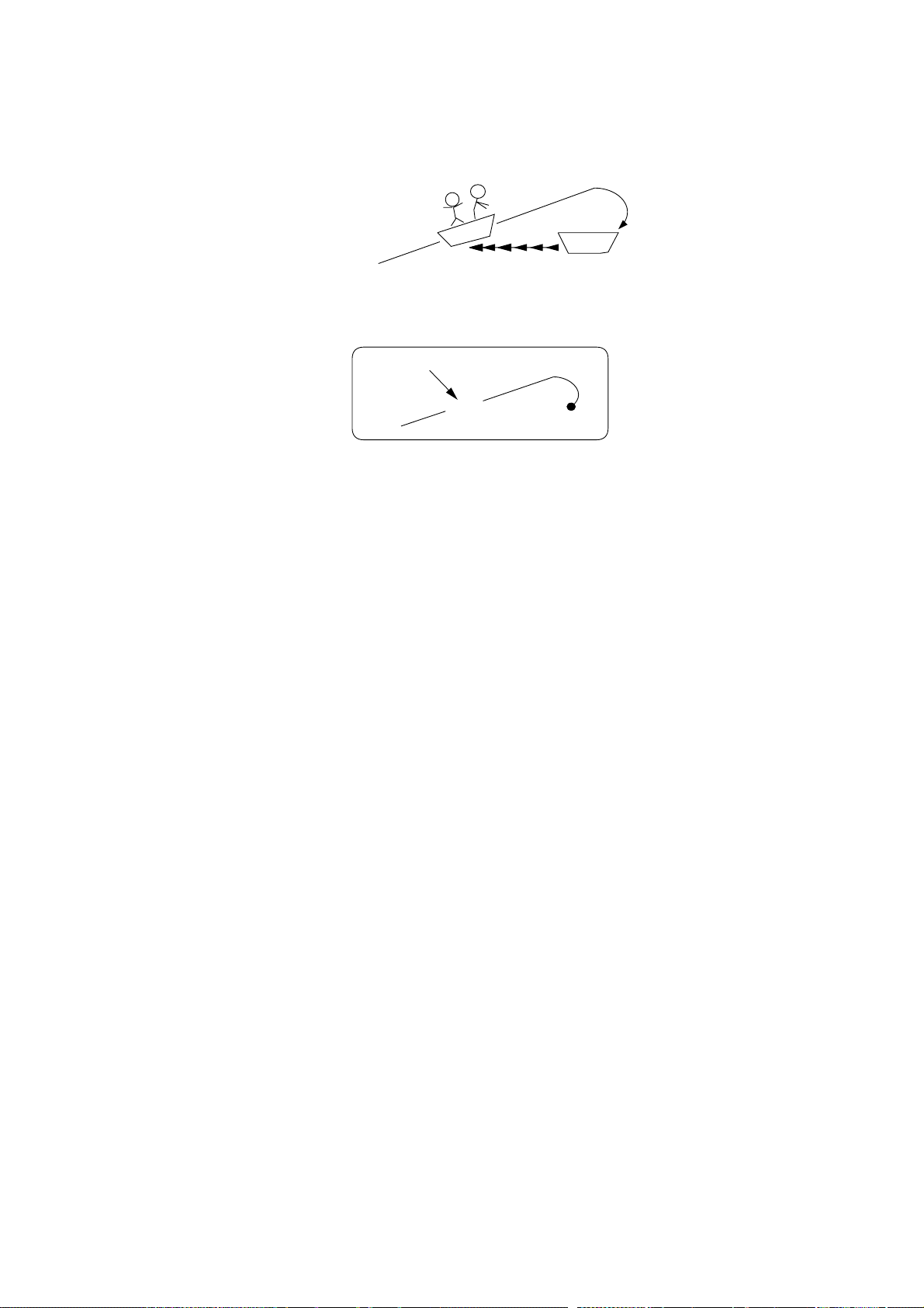
4.4 MOB Mark
The MOB (Man Overboard) mark denotes position of man overboard. This mark can only be
inscribed on the combination and video plotter displays.
Inscribe MOB
mark immediately
when man is
overboard.
MOB mark
Range
and
bearing
M
Current
position
MOB concept
1. Press the [MENU] key.
2. Press the [8] key twice.
3. Press the [2] key to choose 2. MOB. The MOB mark (“M”) is inscribed at own ship’s
position the moment the key is pressed.
4. Press the [MENU] key to close the menu.
A MOB mark can be erased by placing the cursor on it and pressing the [CANCEL/CLEAR]
key.
4-6
Page 30

4. MARKS, LINES
4.5 Origin Mark
The origin mark ( ) is mainly used to find the range and bearing between two targets on
the radar/plotter and plotter displays.
1. Press the [MENU] key.
2. Press the [8] key twice to display the Mark menu.
3. Press the [1] key to choose Mark Selection.
4. Enter [0], [1] to choose Origin Mark .
5. Press the [ENTER/SELECT] key.
6. Place the cursor on target and press the [MENU] key.
7. Place the cursor on the other target.
8. Press the [MARK] key to close the menu.
The (orange) origin mark appears. Check cursor position display at the screen top to find
range and bearing from the origin mark to own ship.
1.054NM
+
357.9° R
Origin mark data
To erase the origin mark, enter 01 at step 4.
4.6 Mark Color
Mark color can be selected as below. Note that the color of the origin mark (orange) cannot
be changed.
1. With the video plotter mode selected, press [MENU], [8], [8].
2. Press the [4] key to choose mark color desired.
3. Press the [ENTER/SELECT] key to register your selection.
4. Press the [MENU] key to close the menu.
4-7
Page 31

Page 32

5.
In navigation terminology, a particular location is known as a “waypoint,” whether it be a
starting point, a destination point or an intermediate point on a voyage.
WAYPOINTS, ROUTES
5.1 Turning Waypoints On/Off
You may choose to turn all waypoints on or off, and the default setting is ON. Note however
that when a route is displayed its waypoints are shown regardless of whether waypoints are
turned on or off.
1. Press the [MENU] key.
2. Press the [1] key twice to display the Video Plot/AIS menu.
3. Press the [9] key twice to choose Coastline/Mark Disp menu.
4. Press the [2] key to choose On.
5. Press the [ENTER/SELECT] key followed by the [MENU] key.
5.2 Entering Waypoints
Waypoints may be entered on the video plotter, combination display, by the cursor, at own
ship’s position, through the waypoint list. You can store 98 waypoints, numbered 01-98.
Waypoints 00 and 99 are special waypoints. Waypoint 00 marks own ship’s position when
destination is selected and waypoint 99 is for waypoint entered at the navigator (GPS, etc.)
5.2.1 Entering waypoints at own ship’s position
1. Press the [MENU] key.
2. Press the [1] key twice to display the Video Plot/AIS menu.
3. Press the [4] key twice to choose Waypoint.
Enter Waypoint
1. ↑
2. Cursor
3. OS Pos.
4. List
5. WPT No.
01
Waypoint menu
4. If you want to register the waypoint under a number different from what is shown below
“WPT No.,” press the [5] key and key in desired waypoint number in two digits (01-98)
and press the [ENTER/SELECT] key. (If you enter a number which already exists, “in
use” appears.) If you do not care to change the waypoint number, go to step 5; the
waypoint will be registered under the number shown below WPT No. Note that waypoint
00 or 99 cannot be entered - these are reserved for own ship position and external
waypoint.
5-1
Page 33

5. WAYPOINTS, ROUTES
5. Press the [3] key (OS Pos) twice, and a waypoint mark with waypoint number inside is
inscribed at own ship’s position.
6. Press the [MENU] key to finish.
If there is no empty waypoint, a beep sounds and no waypoint can be entered. In this case
erase unnecessary waypoints.
5.2.2 Entering waypoints at cursor position
1. Press [MENU], [1], [1], [4], [4].
2. If you want to register the waypoint under a number different from what is shown below
“WPT No.,” press the [5] key, key in desired waypoint number in two digits and then
press the [ENTER/SELECT] key. If you do not care to change the waypoint number, go
to step 3; the waypoint will be registered under the number shown below WPT No.
3. Place the cursor on the location desired for a waypoint.
4. Press the [2] key (Cursor) twice, and a waypoint mark with waypoint number inside is
inscribed at the cursor location.
5. Press the [MENU] key to finish.
5.2.3 Entering waypoints by manual entry of latitude and longitude
1. Press [MENU], [1], [1], [4], [4].
2. Press the [4] key twice to choose List.
Data input cursor
(Waypoint List)
No. Comment
↑
100°00.000'N 000°00.000'E ABCDEFGHJK
200°00.000'N 000°00.000'E 9876543210
u
3 ° . 'N ° . 'E
4 ° . 'N ° . 'E
5 ° . 'N ° . 'E
6 ° . 'N ° . 'E
7 ° . 'N ° . 'E
8 ° . 'N ° . 'E
9 ° . 'N ° . 'E
10 ° . 'N ° . 'E
20 ° . 'N ° . 'E
99 ° . 'N ° . 'E
Enter Lat/Long.
N, E: + S,W: - Delete: CLR Enter: ENT
Escape: MENU
(Japanese characters appear here.)
A B C D E F G H I J K L M N O P Q R S T U V W X Y
Z , - ! ? / & = # _ 1 2 3 4 5 6 7 8 9 0
a b c d e f g h i j k l m n o p q r s t u v w x y
z
Move cursor by using trackball and press ENT.
Character selection cursor
Waypoint list
OK
Available characters
5-2
Page 34

5. WAYPOINTS, ROUTES
3. Operate the trackball to place the cursor on an empty waypoint. You can scroll the list by
placing the cursor at the bottom of the page.
4. Key in latitude and longitude with the numeric keys.
Note: You can switch from North to South, East to West and vice versa with the [-] key. Do
this before entering the data. An entire line of data can be cleared with the
[CANCEL/CLEAR] key.)
5. If you want to enter a comment follow the procedure below. If not, go to step 6.
a) Confirm that the cursor is located in the Comments column. Choose alphanumeric character
with the cursor. (Numerics can be directly entered with the numeric keys. A wrong character
can be erased with the [CANCEL/CLEAR] key.)
b) Press the [ENTER/SELECT] key.
c) Repeat a) and b) to complete the comment.
d) Choose OK.
e) Press the [ENTER/SELECT] key.
6. Press the [ENTER/SELECT] key.
7. Press the [MENU] key to finish.
Waypoint number and waypoint mark are shown on the screen.
5.3 Waypoints
5.3.1 Deleting waypoints with the cursor
1. Use the trackball to select the waypoint to erase.
2. Press the [CANCEL/CLEAR] key.
5.3.2 Deleting waypoints through the waypoint list
1. Press [MENU], [1], [1], [4], [4], [4], [4] to display the waypoint list.
2. Use the trackball to choose the waypoint to erase.
3. Press the [CANCEL/CLEAR] key to delete waypoint.
4. Press the [ENTER/SELECT] key followed by the [MENU] key to finish.
5. Press the [MENU] key.
5-3
Page 35

5. WAYPOINTS, ROUTES
5.4 Creating Routes
In many cases a trip from one place to another involves several course changes, requiring a
series of route points (waypoints) which you navigate to, one after another.
The sequence of waypoints leading to the ultimate destination is called a route. The
RP-180 can automatically advance to the next waypoint on a route, so you do not have to
change the destination waypoint repeatedly. The figure below shows an example of a route
between two ports, involving six waypoints.
You can store up to 10 routes. A route may contain up to 30 waypoints.
PORT
PORT
WAYPOINT 01 WAYPOINT 02
WAYPOINT 03
FORWARD
WAYPOINT 06
REVERSE
WAYPOINT 04
WAYPOINT 05
Sample route
5.4.1 Creating routes with the cursor
1. Press the [MENU] key.
2. Press the [1] key twice to show the Video Plot/AIS menu.
3. Press the [5] key twice to choose Route.
Route
1. Mode = Cursor WPT No. List
2. Speed for TTG = 10.0kt
(Route List)
No. Pts Disp Total TTG
u
1 30 YES 234.56 nm 345.6H In use
2 5 YES 335.67 nm 455.6H
3 3 YES 37.99 nm 19.9H
10 _ _ YES _ _ _._ _ nm _ _ _ _ _._ H
Select mode and route no. by using trackball.
Display: + Not display: Enter: ENT
Delete: CLR
Route menu
4. Press the [1] key to choose Cursor, and press the [ENTER/SELECT] key.
5. Press the [2] key to choose Speed for TTG.
6. Key in ship’s speed with the numeric keys. (This allows for automatic calculation of
time-to-go to waypoints.)
7. Press the [ENTER/SELECT] key.
8. Choose route number with the trackball.
9. Press the [ENTER/SELECT] key.
5-4
Page 36

5. WAYPOINTS, ROUTES
10. As the screen prompts, place the cursor where you want to have a waypoint for the
route.
11. Press the [+] key. (To clear just-selected point, press the [-] key.)
12. Repeat steps 10 and 11 to complete the route.
13. Press the [ENTER/SELECT] key to register the route and the [MENU] key to close the
menu.
5.4.2 Creating routes with waypoints
1. Press [MENU], [1], [1], [5], [5] to display the Route menu.
2. Press the [1] key to choose WPT no., and press the [ENTER/SELECT] key.
3. Press the [2] key to choose Speed for TTG.
4. Key in ship’s speed with the numeric keys. (This allows for automatic calculation of
time-to-go to waypoints.)
5. Press the [ENTER/SELECT] key.
6. Choose route number with the trackball.
7. Press the [ENTER/SELECT] key. The screen for selection of waypoint number appears.
Reg. Route (No. )
WPT Nos. =
- -+- -+- -+- -+ -+- -+- -+- -+- -+- -
- -+- -+- -+- -+ -+- -+- -+- -+- -+- -+- -
- -+- -+- -+- -+ -+- -+- -+- -+- -+- -+- -
(Waypoint List)
No. Comment
↑
134°44.135'N 135°10.856'E ABCDEFGHJK
u
234°40.236'N 135°09.211'E 9876543210
3 ° . 'N ° . 'E
4 ° . 'N ° . 'E
5 ° . 'N ° . 'E
9 ° . 'N ° . 'E
10 ° . 'N ° . 'E
20 ° . 'N ° . 'E
99 ° . 'N ° . 'E
Select WPT and press +key.
To cancel, press -key.
Repeat above steps and press ENT to conclude.
Screen for entering route by waypoints
8. Choose waypoint number with the cursor and press the [+] key. (You may also enter
waypoint number with the numeric keys in which case it is not necessary to press the [+]
key.)
9. Repeat step 8 to complete the route.
10. Press the [ENTER/SELECT] key.
11. Press the [MENU] key to finish.
5-5
Page 37

5. WAYPOINTS, ROUTES
5.4.3 Creating routes from the route list
1. Press [MENU], [1], [1], [5], [5] to display the Route menu.
2. Press the [1] key to choose List, and press the [ENTER/SELECT] key.
3. Press the [2] key to choose Speed for TTG.
4. Key in ship’s speed with the numeric keys. (This allows for automatic calculation of
time-to-go to waypoints.)
5. Press the [ENTER/SELECT] key.
6. Choose route number with the trackball.
7. Press the [ENTER/SELECT] key. The screen for selection of route points appears.
Route (No. 01)
WPT Skip Distance TTG
1 08 YES 0.00 nm 0.0H
u
2 11 NO 135.67 nm 75.7H
3 15 YES 185.07 nm 125.6H
4 18 NO 185.07 nm 125.6H
5 22 NO 234.60 nm 345.6H
6 - - NO - - -.- - nm - - - - -.- - H
7 - - NO - - -.- - nm - - - - -.- - H
8 - - NO - - -.- - nm - - - - -.- - H
9 - - NO - - -.- - nm - - - - -.- - H
10 - - NO - - -.- - nm - - - - -.- - H
30 - - NO - - -.- - nm - - - - -.- - H
Move cursor and enter WPT no.
Skip: - No Skip: +
Delete: CLR Conclude: ENT Escape: MENU
Screen for making route
8. Locate the cursor where you want to enter a route point.
9. Key in waypoint number. (The buzzer sounds if you enter a waypoint which has not been
registered.)
10. Press the [ENTER/SELECT] key.
11. Repeat steps 8-10 to complete the route.
12. Press the [MENU] key to finish.
5-6
Page 38

5. WAYPOINTS, ROUTES
5.5 Turning Route Display On/Off
You may choose to display (or not) a route as follows.
1. Press the [MENU] key.
2. Press the [1] key twice to show the Video Plot/AIS menu.
3. Press the [5] key twice to choose Route.
4. Choose route number with the trackball.
5. Press the [ + ] key to display the route; the [ - ] key to not display it.
6. Press the [ENTER/SELECT] key to register your selection and the [MENU] key to close
the menu.
5-7
Page 39

5. WAYPOINTS, ROUTES
5.6 Deleting Route Waypoints
1. Press [MENU], [1], [1], [5], [5] to display the Route menu.
2. Press the [1] key twice to choose List.
3. Press the [ENTER/SELECT] key.
4. Use the trackball to choose route number.
5. Press the [ENTER/SELECT] key.
6. Use the trackball to choose route waypoint to delete.
7. Press the [CANCEL/CLEAR] key.
8. Press the [ENTER/SELECT] key. The route data changes to reflect deletion.
9. Press the [MENU] key to finish.
5.7 Deleting Routes
1. Press [MENU], [1], [1], [5], [5] to display the Route menu.
2. Choose route number with the trackball.
3. Press the [CANCEL/CLEAR] key.
4. Press the [ENTER/SELECT] key to delete the route.
5. Press the [MENU] key to finish.
5-8
Page 40

6.
This section covers navigation. You can navigate by waypoint, cursor-selected point and
route.
NAVIGATION
6.1 Navigation
6.1.1 Navigating to a waypoint
1. Press the [MENU] key.
2. Press the [1] key twice to show the Video Plot/AIS menu.
3. Press the [6] key twice to choose Destination Set.
Destination
1. ↑
2. Destination
Set
Cancel
3. Mode
Cursor
WPT
Route No.
MOB
Destination set menu
4. Press the [3] key to choose Mode.
5. Press the [3] key again to choose WPT.
6-1
Page 41

6. NAVIGATION
6. Press the [ENTER/SELECT] key.
Destination Set
WPT Nos. =
(Waypoint List)
No. Comment
↑
u
100°00.000'N 000°00.000'E ABCDEFGHJK
200°00.000'N 000°00.000'E 9876543210
3 ° . 'N ° . 'E
99 ° . 'N ° . 'E
Select WPT and press + key.
To cancel, press - key.
- -+- -+- -+- -+ -+- -+- -+- -+- -+- -
- -+- -+- -+- -+ -+- -+- -+- -+- -+- -+- -
- -+- -+- -+- -+ -+- -+- -+- -+- -+- -+- -
Screen for entry of destination waypoints
7. Use the trackball to choose a waypoint. (A waypoint may also be entered with the
numeric keys, in which case omit step 7. If an unregistered waypoint number is entered
the buzzer sounds to alert you.)
8. Press the [+] key to set waypoint. The [-] key can be used to cancel an entry.
9. If you want to navigate to more than one waypoint, repeat steps 6 and 7.
10. Press the [ENTER/SELECT] key. Current position is marked as “00” and a dashed line
connects between it and all waypoints. This line shows the ideal course between
waypoints.
11. Press the [MENU] key to finish.
6.1.2 Navigating to cursor-selected point
1. Press [MENU] [1], [1], [6], [6] to display the Destination menu.
2. Press the [3] key to choose Mode.
3. Press the [3] key to choose Cursor is selected and press the [ENTER/SELECT] key
4. As the screen prompts, use the trackball to place the cursor on location desired for
destination and press the [+] key. (You may choose up to 30 points. To clear a selection,
press [-].)
5. Press the [ENTER/SELECT] key. Current position is marked as “00” and a dashed line
connects between it and all destination waypoints. This line shows the ideal course
between waypoints.
6. Press the [MENU] key to finish.
6-2
Page 42

6. NAVIGATION
6.1.3 Following a route
1. Press [MENU], [1], [1], [6], [6] to display the Destination menu. If a route is currently
selected as destination, its number is shown at the top of the screen.
2. Press the [3] key to choose Route No. and press the [ENTER/SELECT] key.
3. Confirm that Route No. is selected.
4. Press the [ENTER/SELECT] key, and your display now looks something like the one
below.
Destination Set
1. Route nos. =
2. FWD/REV = Forward Reverse
(Route List)
No. Pts Disp Total TTG
u
1 30 YES 234.56 nm 2345.6H
2 5 YES 14.50 nm 41.6H
3 - - YES
---. --
nm
-----.-
H
10 - - YES
Select route and press +key.
To cancel selection, press -key.
Press ENT to conclude.
---. --
nm
-----.-
H
Screen for setting destination by route
If a route is currently used for navigation, the route number appears in 1. Route nos. If
not, “- -“ appears at that location.
5. Press the [2] key to choose the direction in which to traverse the route, Forward or
Reverse.
6. Press the [ENTER/SELECT] key.
7. Use the trackball to select a route. (You also may enter route number with the numeric
keys, in which case omit step 8. If an unregistered route number is entered the buzzer
sounds to alert you.)
8. Press the [+] key. (You can cancel an entry with the [-] key).
9. Press the [ENTER/SELECT] key. Current position is marked as “00” and a dashed line
connects between it and all route waypoints. This line shows the ideal course between
waypoints.
10. Press the [MENU] key to finish.
6.1.4 Navigating to MOB position
MOB must be set beforehand.
1. Press [MENU] [1], [1], [6], [6] to display the Destination menu.
2. Press the [3] key to choose Mode and then MOB.
3. Press the [ENTER/SELECT] key. Current position is marked as “00” and a dashed line
connects between it and MOB position. This line shows the ideal course between
waypoints.
6-3
Page 43

6. NAVIGATION
6.2 Cancelling Navigation
Once you arrive at your ultimate destination you probably won’t need the destination
waypoint. You can cancel it as follows:
1. Press [MENU], [1], [1], [6], [6] to display the Destination menu.
2. Press the [2] key to choose Cancel.
3. Press the [ENTER/SELECT] key followed by the [MENU] key.
Note: MOB destination can also be cancelled by placing the cursor on the MOB mark and
pressing the [CANCEL/CLEAR] key. This can only be done when the MOB is not set
as destination.
6.3 Skipping Route Waypoints
A route waypoint may be deselected temporarily from the route list. Using the following
figure as an example, you would want to temporarily deselect route waypoints 04, since
your ship is to change course at waypoint 05 and head to waypoint 03.
Route points cannot be skipped while following a route.
Port
Waypoint 01
New courseline
Port
Waypoint 06
Sample route in which waypoints are skipped
1. Press [MENU], [1], [1], [5], [5] to display the Route menu.
2. Press the [1] key to choose List and then press the [ENTER/SELECT] key.
3. Use the trackball to choose route number.
4. Press the [ENTER/SELECT key.
Waypoint 02
Waypoint 03
Waypoint 04
Waypoint 05
6-4
Page 44

6. NAVIGATION
Display "Yes" to skip waypoint.
Route (No. 01)
WPT Skip Distance TTG
u
1 08 YES 0.0 nm 0.0H
2 11 NO 135.67 nm 75.6H
3 15 YES 185.07 nm 125.6H
4 18 NO 234.60 nm 234.6H
5 22 NO 258.67 nm 345.6H
6 - - NO - - -.- - nm - - - - -.- - H
7 - - NO - - -.- - nm - - - - -.- - H
8 - - NO - - -.- - nm - - - - -.- - H
9 - - NO - - -.- - nm - - - - -.- - H
10 - - NO - - -.- - nm - - - - -.- - H
30 - - NO - - -.- - nm - - - - -.- - H
Move cursor and enter WPT no.
Skip: - No skip: +
Delete: CLR Conclude: ENT Escape: MENU
Route contents (route no. 1)
5. Use the trackball to choose route point to skip with the cursor.
6. Press [-] key to display YES (in Skip column). The route data changes to reflect skipped
waypoint.
7. Press the [ENTER/SELECT] key followed by the [MENU] key.
To restore a waypoint, press [+] at step 6 in the above procedure.
6-5
Page 45

6. NAVIGATION
(This page intentionally left blank.)
.
6-6
Page 46

7.
ALARMS
There are four conditions which releases visual and audible alarms: Arrival alarm, Anchor
watch alarm, XTE (Cross-track Error) alarm and Border alarm. When an alarm setting is
violated the audible alarm sounds and the alarm icon (
) appears at the bottom right-hand
corner of the display. To silence the buzzer, press the [AUDIO OFF] key.
7.1 Arrival Alarm, Anchor Watch Alarm
The Arrival alarm alerts you when own ship nears a waypoint by the distance set. The
Anchor Watch alarm sounds when own ship is moving when it should be at rest.
Alarm
range
Own ship
: Alarm area
ARRIVAL ALARM
Alarm
setting
Your ship's position where
you start the anchor watch
alarm.
ANCHOR WATCH ALARM
Destination
waypoint
: Alarm
area
Arrival alarm, anchor watch alarm concept
7-1
Page 47

7. ALARMS
Before setting the arrival or anchor watch alarm, set a destination waypoint. For the anchor
watch alarm the destination should be own ship position.
1. Press the [MENU] key.
2. Press the [1] key twice to show the Video Plot/AIS menu.
3. Press the [0] key twice to choose Miscellaneous.
4. Press the [2] key twice to choose Alarm Set.
Alarm Set
1. ↑
2. Arrival/Anchor
Arrival
Anchor
Off
Alarm Range 1. 000 nm
3. XTE/Border
XTE
Border
Off
Alarm Range 1. 000 nm
(Alarm triggered)
XXXXXXXX
XXXXXXXX
Set destination waypoint.
Shows which alarm is sounding.
Alarm Set menu
5. Press the [2] key to choose Arrival or Anchor.
6. Press the [ENTER/SELECT] key.
7. Key in alarm range (0.001-9.999). (To cancel input, press the [CANCEL/CLEAR] key.)
8. Press the [ENTER/SELECT] key.
9. Press the [MENU] key to finish.
To disable the Anchor watch alarm or Arrival alarm, choose Off at step 5 in the above
procedure.
7-2
Page 48

7. ALARMS
7.2 XTE Alarm, Border Alarm
The XTE (cross-track error) alarm warns you when own ship is off its intended course.
The Border alarm alerts you when own ship is nearing an area which you do not want to
approach.
Own ship
position
Intended
course
Own ship's position
: Alarm
XTE ALARM
Setting line
Alarm
setting
Alarm
setting
Destination
waypoint
: Alarm range
BORDER ALARM
XTE alarm, border alarm concept
1. Press [MENU], [1], [1], [0], [0], [2], [2] to display the Alarm Set menu.
2. Press the [3] key to choose XTE or Border.
3. Press the [ENTER/SELECT] key.
4. Key in alarm range (0.001-9.999). (To cancel input, press the [CANCEL/CLEAR] key.)
5. Press the [ENTER/SELECT] key.
6. Press the [MENU] key to finish.
To disable the XTE alarm or Border alarm, choose Off at step 2 in the above procedure.
7-3
Page 49

7. ALARMS
This page intentionally left blank.)
7-4
Page 50

8.
MEMORY CARD OPERATIONS
8.1 Formatting Memory Cards
Before you can save information to a memory card you must prepare its surface by
formatting it. Formatting is a routine procedure you must perform on new cards before you
can use them with this unit. You have to initialize them only once. You can format cards
you’ve used before, however, in which case all prior information on them is erased.
1. Press the [MENU] key.
2. Press the [1] key twice.
3. Press the [8] key twice to open the Memory Card menu.
Memory Card
1. ↑
2. Save Data
3. Display Card Data
4. Play Back Data
Memory card menu
8-1
Page 51

8. MEMORY CARD OPERATIONS
4. Press the [2] key twice to open the Save Data menu.
Save Data
1.
2. Mark
3. WPT
4. Track (Own Ship)
5. Track (Targets)
6. Mark (RadarMap)
7. Initial Setting
8. Delete Card Data
9. Format
0.
l
Line
l
Route
Save Data menu
5. Press the [9] key twice to choose Format.
6. As the screen prompts, press the [ENTER/SELECT] key to format the card. “Formatting”
appears while the card is being formatted, and “Formatting completed” when formatting
is completed.
7. Press the [MENU] key to finish.
8-2
Page 52

8. MEMORY CARD OPERATIONS
8.2 Saving Screen Contents to Memory Card
The memory cannot store track and marks indefinitely. For this reason, important track and
marks should be saved to a memory card. A memory card can store 50 files. For 6,000
track points, for example, the card can store eight files (card memory capacity: 512 KB).
1. Insert a formatted memory card in the card slot.
2. Press [MENU], [1], [1], [8], [8] to display the Memory Card menu.
3. Press the [2] key twice to display the Save Data menu.
4. Choose item to save by pressing appropriate numeric key twice: [2], marks/lines; [3],
routes/waypoints; [4], own ship’s track; [5], other ship’s tracks; [6], marks, or [7], initial
settings.
Mark•Line (L SLOT)
Date Pts.
u
00 New File
01
TOTAL NO. OF FILES = 1
Data input cursor
Move cursor by using trackball and press ENT.
Escape : MENU
(Japanese characters appear here.)
A B C D E F G H I J K L M N O P Q R S T U V W X Y
Z , - ! ? / & = # _ 1 2 3 4 5 6 7 8 9 0
a b c d e f g h i j k l m n o p q r s t u v w x y
z (OK)
Move cursor by using trackball and press ENT.
Mark●Line Save menu
5. Operate the trackball to choose “New file” and press the [ENTER/SELECT] key.
8-3
Page 53

8. MEMORY CARD OPERATIONS
6. Assign a file name as below. A file name may contain 32 alphanumeric characters. For
example, assign the file name FURUNO1.
(a) Choose the character “F” with the trackball.
(b) Press the [ENTER/SELECT] key. (You can change a wrong character by choosing it with the
trackball and the entering correct character. You may cancel an entire line of data with the
[CANCEL/CLEAR] key.)
(c) Choose the character “U” with the trackball and press the [ENTER/SELECT] key.
(d) Enter the remaining characters.
(e) Choose OK.
7. Press the [ENTER/SELECT] key. “Recording” appears while data is being recorded.
8. Press the [MENU] key to finish.
Write protect tab
The write protect tab on a memory card prevents writing over information stored on the card.
Slide the tab rightward to write protect a memory card.
Slide tab right to
write protect.
Write protect tab on memory card
8-4
Page 54

8. MEMORY CARD OPERATIONS
8.3
Displaying Memory Card Contents on the Display
Up to eight files may be played back on the radar display.
1. Insert memory card in card slot.
2. Press [MENU], [1], [1], [8], [8] to display the Memory Card menu.
3. Press the [3] key twice to choose Display Card Data.
Display Card Data (L SLOT)
Disp
u
01 1234567890123456 (2004-03-27) YES
7890123456789012 MARK 44 NO
02 Aimee (2004-03-27) NO
WPT 13
03
10
(TOTAL NO. OF FILES = 2)
Move cursor: Trackball
Display : +
Not display :
Register : ENT
Escape : MENU
-
Display Card Data menu
4. Operate the trackball to choose the file to display.
5. Press the [+] key to display Yes; or [-] to display No.
6. Press the [ENTER/SELECT] key followed by the [MENU] key.
8-5
Page 55

8. MEMORY CARD OPERATIONS
8.4 Playing Back Memory Cards
Memory card contents can be played back on the screen. This feature is useful for editing
and copying card contents.
1. Insert memory card in card slot.
2. Press [MENU], [1], [1], [8], [8] to display the Memory Card menu.
3. Press the [4] key twice to choose Play Back Data.
Play Back Data
1.
2. Mark
3. WPT
4. Track (Own Ship)
5. Track (Targets)
6. Mark (RadarMap)
7. Initial Setting
8.
9.
0.
l
Line
l
Route
Play Back Data menu
4. Press appropriate numeric key among 2-7 to choose data to play back.
5. Press the [ENTER/SELECT] key. File list appears.
6. Operate the trackball to choose file to play back.
7. Press the [ENTER/SELECT] key followed by the [MENU] key.
8-6
Page 56

8. MEMORY CARD OPERATIONS
8.5 Erasing Files from Memory Cards
You can erase unnecessary files as follows:
1. Press [MENU], [1], [1], [8], [8] to display the Memory Card menu.
2. Press the [2] key twice to choose Save Data.
3. Press the [8] key twice to choose Delete Card Data.
Delete Card Data (L SLOT)
Date Pts.
u
01 1234567890123456 (2004-04-10) 1234
MARK
02 Aimee (2004-03-27 1234
WPT
03
04
05
06
10
(TOTAL NO. OF FILES = 02)
Move cursor by using trackball and press ENT.
Escape: MENU
Delete card data menu
4. Operate the trackball to choose file to erase.
5. Press the [ENTER/SELECT] key.
6. Press the [ENTER/SELECT] key again.
7. Press the [MENU] key to close the menu.
8-7
Page 57

8. MEMORY CARD OPERATIONS
(This page intentionally left blank.)
8-8
Page 58

9.
OTHER FUNCTIONS
9.1 Entering Ship’s Position Manually
Ship’s speed is normally input by the navigator connected to the radar. If the navigator fails
enter ship’s position manually as follows:
1. Press the [MENU] key.
2. Press the [1] key twice to show the Video Plot/AIS menu.
3. Press the [0] key twice to choose AIS/Miscellaneous1.
4. Press the [7] key twice to choose Miscellaneous2.
MIscellaneous2
1. ↑
2. Pos. Sensor
Navaid Manual
3. Own Ship Pos.
00°00.000'N
000°00.000'E
4. Display All Card Data
5. Delete Data
6. All Delete
N, E; + S, W: -
Miscellaneous2 menu
5. Press the [3] key to choose Own Ship Pos.
6. Key in latitude position of ship. (Use the [-] key to switch latitude coordinate from North
to South; [+] from South to North.)
7. Press the [ENTER/SELECT] key.
8. Key in longitude position of ship. (Use the [-] to switch latitude coordinate from East to
West; [+] from West to East.)
9. Press the [ENTER/SELECT] key.
10. Press the [2] key to choose Manual.
11. Press the [ENTER/SELECT] key to register your selection.
12. Press the [MENU] key to finish.
9-1
Page 59

9. OTHER FUNCTIONS
9.2 Smoothing
Own ship’s track may be traced on the screen with a crooked line even though the ship is
running straight. This is due to navaid signal variation, and can be compensated by
adjusting the smoothing factor. A smoothing setting between 00 and 15 is available. The
higher the figure the more the track is smoothed however too high a setting slows response
time to speed and course changes.
1. Press [MENU], [1], [1], [0], [0], [5], [5] to display the Initial Setting menu.
Initial Setting
1. ↑
2. Smoothing
00 (0-15)
Initial setting menu
2. Press the [2] key to choose Smoothing.
3. Key in smoothing factor in two digits.
4. Press the [ENTER/SELECT] key to register your selection.
5. Press the [MENU] key to finish.
9.3 Viewing Chart Card Contents
You may display the contents of the chart card on the smallest range scale as follows:
1. Press the [MENU] key.
2. Press the [1] key twice to show the Video Plot/AIS menu.
3. Press the [0] key twice to choose AIS/Miscellaneous1.
4. Press the [7] key twice to choose Miscellaneous2.
5. Press the [4] key twice to choose Display All Card Data.
6. Press the [ENTER/SELECT] key followed by [MENU] key to finish.
9-2
Page 60

9.4 Adjusting Brilliance
9.4.1 Chart features
You may adjust the brilliance of chart features as follows:
1. Press [MENU], [9], [9], [9], [9] to display page 2 of the Brill menu.
PLOTTER BRIL
1. ↑
2. LAND
3. GRID
4. MARK
5. CONTOUR
6. COLOR
9. OTHER FUNCTIONS
Brill menu, page 2
2. Press appropriate numeric key among 2-5 to choose item to change brilliance.
3. Use the VRM control to adjust brilliance. Watch the bar graph to judge brilliance level.
The range of the bar graph is 10% to 100%.
4. Press the [ENTER/SELECT] key to register and the [MENU] key to close the menu.
9.4.2 Markers
The brilliance of tracks (own and other ships’), AIS symbols, marks and lines may be adjust
as follows:
1. Press [MENU], [9], [9], [6] to choose MARK.
2. Use the VRM control to adjust brilliance.
3. Press the [ENTER/SELECT] key.
4. Press the [MENU] key to finish.
9-3
Page 61

9. OTHER FUNCTIONS
9.5 Clearing All Data
You may clear all track, marks, waypoints and routes to start afresh.
1. Press the [MENU] key.
2. Press the [1] key twice to show the Video Plot/AIS menu.
3. Press the [0] key twice to choose AIS/Miscellaneous1.
4. Press the [7] key twice to choose Miscellaneous2.
5. Press the [5] key twice to choose Delete Data.
6. Press the [ENTER/SELECT] key..
7. Press the [MENU] key to finish.
9.6 Restoring Default Settings
1. Press the [MENU] key.
2. Press the [1] key twice to show the Video Plot/AIS menu.
3. Press the [0] key twice to choose AIS/Miscellaneous1.
4. Press the [7] key twice to choose Miscellaneous2.
5. Press the [6] key twice to choose All Delete.
6. Press the [ENTER/SELECT] key.
7. Press the [ENTER/SELECT] key again.
8. Reset the power.
9-4
Page 62

9. OTHER FUNCTIONS
9.7 Marker Colors on Chart Cards
You may change the color of grid, marks, land and depth contour as follows.
1. Press [MENU], [9], [9], [9], [9], [6], [6] to display the Plotter Color menu.
PLOTTER COLOR
1. ↑
2. MARK
R Y G C
M B W
3. GRID
R Y G C
M B W
4. LAND
R Y G C
M B W
5. CONTOUR
R Y G C
M B W
Plotter Color menu
2. Press appropriate numeric key to choose marker and color desired. R, Red; Y, Yellow; G,
Green; C, Cyan (Light-blue); M, Magenta; B, Blue, W, White.
3. Press the [ENTER/SELECT] key to register your selection and the [MENU] key to close
the menu.
9-5
Page 63

9. OTHER FUNCTIONS
9.8 Apportioning the Memory
The memory holds a total of 40,000 points of tracks and marks, and the default memory
apportion is 20,000 points each of tracks and marks. However, you may change that setting
to suit your operating needs as follows:
Note: All track and marks are erased when the memory is reapportioned.
1. Press the [MENU] key.
2. Press the [1] key twice to show the Video Plot/AIS menu.
3. Press the [0] key twice to choose AIS/Miscellaneous1.
5. Press the [4] key twice to choose Apportion Memory.
Apportion Memory
1. ↑
2. Track Memory
40000 pts
(MAX 40000PTS)
Current Apportion
Track: 20000 pts
Mark: 20000 pts
CAUTION: Changing memory
apportion deletes tracks
and marks in memory.
Enter points of track
memory, followed by ENT.
Mark Memory =
40000 - Track Memory
Apportion memory menu
5. Press the [2] key to choose Track Memory.
6. Enter the memory capacity desired for track points.
7. Press the [ENTER/SELECT] key.
8. Press the [ENTER/SELECT] key again.
9. Press the [MENU] key.
9-6
Page 64

10.
The AIS (Automatic Identification System) feature automatically provides navigation data on
AIS-equipped ships.
AIS
WARNING
Confirm compass reading on radar
and gyrocompass readout when the
bearing of AIS targets do not match
that of corresponding radar targets.
10.1 Changing Function of [F2] Key to AIS
If desired the [F2] can be programmed to open the AIS(1) menu.
1. Press the [STBY/TX] key to set the radar in stand-by.
2. Press the [MENU] key.
3. Press the [6] key twice to open the [FUNC] menu.
4. Press the [7] key twice to open the [F2 SET] menu.
5. Rotate the VRM control to choose “32.* AIS(1) MENU” (*: 31 for IMO-type radar).
6. Press the [ENTER/SELECT] key to register the function of the [F2] key as AIS.
7. Press the [MENU] key to close the menu.
Note: The [F2] key can also be assigned to display basic AIS data (33.* AIS DATA; *: 32 for
IMO-type radar). For further details see paragraph 10.5.1.
10-1
Page 65

AIS
10.2 Turning AIS Feature On/Off
1. Press the [F2] key to open the AIS(1) menu.
[AIS(1)]
1. Activate Target
2. Sleep Target
3. Basic Data
4. [Extended Data]
5. Lost Target
6. [Message]
7. Activate All Targets
8. Sleep All Targets
9. AIS
Off Func Disp
0. [AIS(2)]
AIS(1) menu
2. Press the [9] key to choose Off, Func, or Disp as appropriate.
Off: All AIS symbols erased and the AIS function is deactivated.
Func: All AIS symbols are erased, but all other AIS functions (collision watch, etc.) are
remain active.
Disp: Al targets received from the AIS transponder are displayed with symbols, and
all AIS functions (collision watch, etc.) are active.
3. Press the [ENTER/SELECT] key. “AIS:F” (FUNCTION) or “AIS:D” (DISPLAY) appears at
the top right hand corner on the display.
4. Press the [MENU] key to close the menu.
When DISP is selected, AIS-equipped ships are marked on the display at their current
position with the appropriate AIS symbol as shown below.
Activated target
Sleeping target
Dangerous
target
Lost target
Target selected
for data display
AIS symbols
Note 1: For the setting Func or Off, all AIS symbols are erased from the screen, however
AIS functions continue internally. The setting Disp will show all AIS targets on the
screen.
Note 2: AIS symbols are momentarily erased after the screen is redrawn when bow
direction is changed in the Head-up mode.
Note 3: The AIS(1) menu can also be opened by using the [MENU] key. The keying
sequence is [MENU], [1], [1], [0], [0], [8], [8].
Note 4: AIS is automatically turned off under any of the the conditions noted below and, if
the condition continues, the function “Disp” or “Func” cannot be selected.
a) EPFS or gyro alarm generated.
b) Manual ship’ speed is used. (See 9.1. IMO-type radar only.)
c) Receiving DTM sentence and it does not contain WGS-84. (IMO-type radar
only)
10-2
Page 66

AIS
10.3 Activating Targets
1. Use the trackball to place the cursor on the sleeping AIS target (indicates only the
presence of a vessel equipped with AIS in a certain location) you wish to activate; that is,
know more about a vessel’s motion.
2. Press the [F2] key to open the AIS(1) menu.
3. Press the [1] key (Activate Target) to activate the target. The activated AIS target symbol
is superimposed on the radar echo as below.
SOG and
COG vector
*1, *2
Activated target
*1 = Length adjustable on the PLOT menu 1 with 4. VECTOR TIME.
*2 = Vector shows STW (speed thru water) and CSE (course) when water tracking
mode is selected at the radar.
*3 = If there is no heading data, the line points in direction of COG.
4. Press the [MENU] key to close the menu.
Dangerous target
Turning
direction
Heading
line*3
When an activated AIS target violates the CPA/TCPA alarm setting set on the PLOT menu 1
its symbol changes to the dangerous target symbol (red and flashing) and the indication
“A-CLSN” appears. Press the [AUDIO OFF] key to acknowledge the CPA/TCPA alarm. The
audio alarm is silenced and the symbol stops flashing. Take appropriate action to avoid
collision.
Thicker than
activated target
Dangerous target
10-3
Page 67

AIS
10.4 Sleeping Targets
10.4.1 Sleeping specific AIS target
You may “sleep” an AIS target as below when the screen becomes filled with targets. Note
that targets that have been activated automatically cannot be “slept.”
1. Use the trackball to place the cursor on an activated AIS target symbol.
2. Press the [F2] key to open the AIS(1) menu.
3. Press the [2] key (Sleep Target) to sleep the target.
4. Press the [MENU] key to close the menu. The target is marked with the sleeping target
symbol, whose triangle is smaller than that of the activated AIS target symbol.
Sleeping target
10.4.2 Sleeping all AIS targets
1. Press the [F2] key to open the AIS(1) menu.
2. Press the [8] key (Sleep All Targets) to sleep all targets.
3. Press the [MENU] key to close the menu.
10.4.3 Activating all sleeping AIS targets
1. Press the [F2] key to open the AIS(1) menu.
2. Press the [7] key (Activate All Targets) twice.
3. Press the [MENU] key to close the menu.
10-4
Page 68

10.5 Displaying Target Data
10.5.1 Basic target data
1. Place the cursor on an AIS target symbol.
2. Press the [ENTER/SELECT] key to show the target’s basic data. The target is marked
as below.
Activated target selected for data display
AIS
AIS target, fusion target no.
Call sign
Bearing from own ship to target
Range from own ship to target
Course over ground
Speed over ground
CPA
TCPA
* = CSE (course) when water tracking mode is selected at radar.
# = STW (speed thru water) when water tracking mode is selected at radar.
AIS 02 TRUE VECT
1436782 6min BT
BRG 234.1
RNG 9.92NM
COG* 321.2
SOG# 21.1KT BT
CPA 2.8NM
TCPA 23:50
°
T
°
T BT
AIS target vector
orientation
(TRUE or REL)
Vector length;
BT: Bottom Tracking
or
WT: Water Tracking
Basic data display
Note 1: You may also show basic data by pressing the [F2] key followed by the [3] key
(Basic Data). Basic data is hidden by the AIS(1) menu; close the AIS(1) menu to
show basic data.
Note 2: If an ARPA symbol is hidden beneath and AIS symbol, press the [ENTER/SELECT]
key to display ARPA data. In this case, use 3. Basic Data (or [F2] key programmed
for “33. AIS DATA) on the AIS(1) menu to display AIS data.
10-5
Page 69

AIS
10.5.2 Extended target data
1. With basic data displayed as in paragraph 10.5.1, press the [F2] key to open the AIS
menu.
2. Press the [4] key (Extended Data) to display the selected target’s extended data.
[Extended Data]
1.
Ship’s name
Name: Voyager
Call sign
Latitude
Longitude
Heading
Rate Of Turn
Position-fixing device
Position accuracy (High, Low)
Navigation status
MMSI No.
IMO No.
Length
Width
Draft
Destination
Estimated Time of Arrival
Fusion (AIS and ARPA combined) target no.
Type of ship and cargo
Call Sign: 1436782
Lat:
°
44.2345’N
34
Long:
°
32.1890’E
135
Hdg: 323
ROT: R 050.0°/min
Pos.Sns:
GPS
Pos. Acc: High
Nav. State:
at anchor
MMSI NO.: 107374182
IMO NO.: 12354876
Ship Length: 187m
Ship Width: 28m
Ship Draft: 12.2m
Destination:
Osaka
ETA: 01/Feb 12:59
Fusion: 02
Type of Ship & Cargo Type:
Fishing
°
Extended data display
3. Press the [MENU] key to close the data display.
10-6
Page 70

AIS
10.6 Lost Target
A target is declared a lost target when no data is received for three to five reporting intervals.
When this occurs, the target is marked with the (flashing) lost target symbol and the
indication “A-LOST” appears. Press the [CANCEL/CLEAR] key to acknowledge the lost
target, and the lost target disappears. However, the target which becomes a lost target is a
activated target or a sleeping target within the lost target range. (See paragraph 10.11.)
Lost target
Confirming a lost target
1. Use the trackball to place the cursor where there is not ARPA target, marks nor lines.
2. Press the [CANCEL/CLEAR] key.
Note 1: You may also confirm a lost target by pressing [F2] and [5] (Lost Target).
Note 2: The AIS data transmission interval depends on other ship’s speed. For example,
the AIS data is transmitted every 10 seconds on a ship speed of 0-14 kt and every
two seconds on the ship speed of more than 23 knots. For details see the owner’s
manual of the AIS.
10.7 Messages
You may display messages received by the AIS transponder as below.
10.7.1 Displaying messages manually
1. Press the [F2] key to display the AIS(1) menu.
2. Press the [6] key ([MESSAGE]) twice to display the MESSAGE menu.
[Message]
No of messages saved
(Max. 5 for each type of message.
1 is the latest message.)
Safety message addressed to your ship
Safety messge addressed to all ships
Binary message addressed to your ship
Binary message addressed to all ships
Automatic displaying of message
* = Binary messages are messages
other than safety messages.
Message menu
1 [AIS(1)]
2 Safety Related Message
(Addressed)
3 Safety Related Message
(Broadcast)
4 Binary Message*
(Addressed)
5 Binary Message*
(Broadcast)
6 Auto Display
On Off
1
1
1
1
10-7
Page 71

AIS
3. Press appropriate numeric key among 2-5 to choose the type of message you want to
see. The example below shows a safety related message (addressed).
[Message]
1
1
1
1
Message type
Ship sending message
Ship receiving message
Date message received
Time message received
Text of message
1 [AIS(1)]
2 Safety Related Message
(Addressed)
3 Safety Related Message
(Broadcast)
4 Binary Message*
(Addressed)
5 Binary Message*
(Broadcast)
6 Auto Display
On Off
=========================
Safety Related Message
(Addressed)
Source ID: 012343215
Dest. ID: 045673289
Date: 01/30/2004
Time: 10:32:41
Message
STORM WARNING VICINITY
OF 35
°
N 135°W.
Safety related message
4. Key in the same number entered at step 3.
5. Press the [ENTER/SELECT] key to display the message.
6. Press the [MENU] key to close the message display.
10.7.2 Automatically displaying messages
You can automatically display a message when it is received.
1. Press the [F2] key to display the AIS(1) menu.
2. Press the [6] key ([Message]) twice to show the MESSAGE menu.
3. Press the [6] key (Auto Display) once or twice to choose ON.
4. Press the [ENTER/SELECT] key.
5. Press the [MENU] key to close the menu.
When a message is received the “message” display is automatically opened, showing the
received message. To close the display, press the [MENU] key.
10-8
Page 72

AIS
10.8 History Display
The history display shows equally time-spaced dots marking past positions of activated
targets being tracked. A new dot is added at preset time intervals until the preset number is
reached. If a target changes its speed, the spacing will be uneven. If it changes course, its
plotted course will not be a straight line.
Below are sample history displays.
(a) Ship turning
(b) Ship running
straight
(c) Ship reduced
speed
Sample history displays
10.8.1 Turning history display on/off
1. Press the [F2] key to open the AIS(1) menu.
2. Press the [0] key twice to show the AIS(2) menu.
[AIS(2)]
1. [AIS(1)]
2. History
On Off
3. History Points
5 10
4. History Interval
10 30sec 1
2 3 6min
5. Symbol Color
R* Y* G* C
M B W*
6. ROT Tag
000.1° /min
7. Auto Activate
On Off
Range = 000.0nm
8. Lost Target Range
000.0nm
9.
0. [(AIS(3)]
(d) Ship increased
speed
*: Not available on IMO-type radar.
AIS2 menu
3. Press the [2] key (History).
4. Further press the [2] key again to turn the history display on or off as appropriate.
5. Press the [ENTER/SELECT] key.
6. Press the [MENU] key to close the menu.
10-9
Page 73

AIS
10.8.2 Choosing history display attributes
You may choose history point color, the number of history points to show per history plot
interval and the history plot interval as below. Note that the color of the history points is the
same as the symbol color.
1. Press the [F2] key to open the AIS(1) menu.
2. Press the [0] key twice to show the AIS(2) menu.
3. Press the [3] key (History Points).
4. Further press the [3] key to choose number of history points to display per plotting
interval: 5 or 10.
5. Press the [ENTER/SELECT] key.
6. Press the [4] key (History Interval).
7. Press the [4] key again to choose history interval desired among 10, 30 s; 1, 2, 3 and 6
min.
8. Press the [ENTER/SELECT] key.
9. Press the [MENU] key to close the menu.
10.9 AIS Symbol Color
You may choose the color for the AIS symbols among red*, yellow*, green*, cyan, magenta,
blue and white*. (* = Not available on IMO-type radar.)
1. Press the [F2] key to open the AIS(1) menu.
2. Press the [0] key twice to show the AIS(2) menu.
3. Press the [5] key (Symbol Color).
4. Further press the [5] key to choose color desired.
5. Press the [ENTER/SELECT] key.
6. Press the [MENU] key to close the menu.
10-10
Page 74

AIS
10.10 Automatic Target Activation
You may automatically activate all targets within a specific distance from own ship as below.
Note that you may also automatically activate all targets within the ARPA’s automatic
acquisition zone or guard zone. When a target enters the ARPA’s automatic acquisition
zone or guard zone, it is automatically marked with the activated target symbol. If the
activated target goes out of the ARPA automatic acquisition zone or the guard zone it still is
an activated target. When a target enters the guard zone, the display shows “A-GZ” at the
lower right hand corner of the display.
1. Press the [F2] key to open the AIS(1) menu.
2. Press the [0] key twice to show the AIS(2) menu.
3. Press the [7] key (Auto Activate).
4. Press the [7] key again to choose ON and then press the [ENTER/SELECT] key.
5. Press the [ENTER/SELECT] key.
6. Use the numeric keys to enter automatic activation range (000.1 to 999.9 nm).
7. Press the [ENTER/SELECT] key.
8. Press the [MENU] key to close the AIS menu.
10.11 Lost Target Range
Set the distance at which an AIS target is declared a lost target when no AIS data is
received for six minutes or five reporting intervals, whichever is the shorter. When this
feature is activated the following occurs:
•
Sleeping targets within the lost target range for which no data is received are marked with
the lost target symbol.
•
Sleeping targets out of the lost target range are erased.
•
Any activated AIS target from which you are not receiving AIS data is marked with the lost
target symbol regardless of range to the target.
1. Press the [F2] key to open the AIS(1) menu.
2. Press the [0] key twice to show the AIS(2) menu.
3. Press the [8] key (Lost Target Range).
4. Use the numeric keys to enter lost target range (000.1 to 999.9 nm).
5. Press the [ENTER/SELECT] key.
6. Press the [MENU] key to close the AIS menu.
To disable this feature, enter all zeroes at step 4 in the above procedure.
10-11
Page 75

AIS
10.12 ROT Display Setting
You may set the lower limit of the ROT (Rate Of Turn) at which the heading line on target
symbols will point in direction of turning.
1. Press the [F2] key to open the AIS(1) menu.
2. Press the [0] key twice to show the AIS(2) menu.
3. Press the [6] key (ROT Tag).
4. Use the numeric keys to enter ROT (000.1 to 720.0°/min).
5. Press the [ENTER/SELECT] key.
6. Press the [MENU] key to close the AIS menu.
ROT display
10-12
Page 76

10.13 Combining AIS with ARPA (fusion)
If equipped with ARPA it may be jointly used with the AIS. In this case specify the
parameters for which an ARPA target is converted to an AIS target.
1. Confirm that "MAN" or “AUTO+MAN” is shown at the right-hand corner of the display.
2. Press the [F2] key to open the AIS(1) menu.
3. Press the [0] key twice to open the AIS(2) menu.
4. Press the [0] key twice to open the AIS(3) menu.
[(AIS(3)]
1.
2. Fusion
On Off
Posn 0.000NM
Rng 0.000NM
Brg 00.0
Spd 0.0KT
Cse 00.0
°
°
AIS
AIS Alarm Message
NO ALARM
AIS3 menu
4. Press the [2] key (FUSION).
5. Press the [2] key again to choose ON and press the [ENTER] key.
6. Enter the information below, pressing the [ENTER] key after entering each data. This
information will be used to determine which ARPA targets to convert.
Posn: Range between AIS target and ARPA target.
Rng: Enter the range difference from own ship to AIS target and ARPA target.
Brg: Enter the bearing difference from own ship to AIS target and ARPA target.
Spd: Enter the speed difference between AIS target and ARPA target.
Cse: Enter the course difference between AIS target and ARPA target.
7. Press the [MENU] key to close the AIS menu.
If the information above is within the corresponding value of the ARPA and AIS targets, the
targets are judged to be the same, the ARPA symbol is erased and only the AIS symbol is
displayed. Further, “A-FSN” appears at the bottom right corner of the display at the time of
conversion and the ARPA target no. appears next to the AIS symbol.
Note: An ARPA target whose speed is less than 1 kt is converted to an AIS target if it meets
all other criteria other than course.
10-13
Page 77

AIS
10.14 AIS System Messages
AIS system messages are displayed at the bottom right corner of the screen. The table
below shows the AIS system messages and their meanings.
AIS system messages
Message Meaning
A-FSN ARPA target converted to AIS target. The indication
disappears when the target no longer meets the
criteria set for the fusion feature. When the
message A-RCV is displayed, A-FSN not displayed.
A-CLSN CPA/TCPA of an AIS target is below preset value.
A-LOST Lost target
A-RCV Not receiving AIS data
A-WT This message appears when the water tracking
mode is set at the radar and STW and CSE are not
available. In this case the speed and course vector
on the AIS symbol disappears and SOG and COG
for the AIS target are displayed (on the basic
display). See the table on the next page for
conditions.
A-GZ Displayed when a target enters the ARPA guard
ring.
A-CPA CPA/TCPA of the AIS target cannot be calculated
because the “A-WT” alarm has been violated. *** is
shown at the CPA/TCPA data location on the basic
display. See the table on the next page for
conditions.
A-FULL Displayed when 1000 AIS targets have been
received. (The radar can only display 1000 AIS
targets closest in range to own ship.)
10-14
Page 78

AIS
Remarks
Msg on
IMO only
VBW
VBW
VTG
Log
BT data
WT data
Pulse
See Note 2
A-CPA
See Note 2
A-CPA
Not available
on IMO spec.
LOG
A-CPA
LOG
A-WT
A-CPA
A-WT
A-CPA
LOG
See Note 2
A-CPA
A-CPA
LOG
A-CPA
BT data of VBW
and gyro
VTG
WT data
of VBW
Ship’s speed and course data and A-WT, A-CPA alarm generating conditions
BT WT BT WT
Own ship speed data (Note 3) Own ship course data (Note 3) Msg when signal below is lost (IMO and Non-IMO)
Mode
VTG VTG
VTG VTG
calculation
VTG VTG A-CPA
course
BT Target based speed Target based
Set/
Drift
Speed
Source
MAN OFF WT VTG MAN VTG GYRO A-WT A-CPA
A-CPA
MAN ON BT A-CPA
LOG OFF WT VTG Log Pulse VTG GYRO LOG A-WT
A-CPA
LOG ON BT A-CPA A-CPA
LOG
NAV OFF/ BT VTG VTG A-CPA
ON
LOG OFF/ BT BT data of VBW BT data of VBW and
(S-BT) ON Gyro calculation
ON
LOG OFF WT VTG
(S-WT)
LOG ON BT
REF OFF/
(S-WT)
Note 1: "VTG" means VTG or RMC data, and the order of priority is VTG>RMC. MAN means manually entered ship’s speed; S/D means SET and DRIFT.
Note 2: "SET DRIFT" shown in red characters in this condition.
Note 3: Own ship speed and course data show the data which is used used to calculate CPA/TCPA and WT vector of AIS targets.
10-15
Page 79

AIS
10.15 AIS Alarm Message
The AIS(3) menu provides AIS alarm message information ($AIALR sentence) from the AIS
transponder. When an AIS alarm message is received “A-ALM” appears at the bottom
right-hand corner of the screen.
10-16
Page 80

11.
MAINTENANCE,
TROUBLESHOOTING
11.1 Replacement of Batteries
The battery icon ( ) appears on the display when the voltage of the memory card battery
or the battery on the RP Board is low. To find out which battery it is, conduct the diagnostic
test as described in Paragraph 11.2. “NG” appears as a battery check results when battery
voltage is low. Replace the battery at your earliest convenience.
The life of the both batteries is about three years. For replacement of the battery on the RP
Board, contact your dealer.
Battery Type Code No.
Memory Card Battery CR2025 000-141-093
Battery on RP Board CR2450-F2ST2L 000-144-941
Replacement of memory card battery
Follow the instructions below to replace the battery in a memory card. Replace the battery
within 10 minutes of removal to prevent loss of data.
1. With the memory card oriented as shown below, slide the stopper on the memory card
leftward.
2. Pull out the battery case and remove the battery.
3. Insert new battery in battery case positive (+) side up.
4. Set battery case to memory card.
Stopper
"+" mark
up
Battery case
Replacement of memory card battery
Note: Dispose of used batteries according to local regulations.
11-1
Page 81

11. MAINTENANCE, TROUBLESHOOTING
11.2 Diagnostic Test
1. Press the [MENU] key.
2. Press the [1] key twice to show the Video Plot/AIS menu.
3. Press the [0] key twice to choose AIS/Miscellaneous1.
4. Press the [6] key twice to choose Test.
The diagnostic test displays program version no., checks the ROM, RAM, DPRAM,
SRAM, internal battery, memory card battery and serial input(*2) for proper operation,
displaying OK or NG (No Good) as the check result. For NG at ROM, RAM, DPRAM or
SRAM contact your agent or dealer for advice. DIP switch setting is also shown.
TEST [RP-1] [RP-2]
Program No. 0359219-xx* 0359220-xx*
ROM OK OK
RAM OK OK
DPRAM OK OK
SRAM OK
DIP SW (1234) 00 00
Main Board Batt. OK
Card Batt. (Right) *1 OK
Card Batt. (Left) *1 OK
Card (Right) *1 OK
Card (Left) *1 OK
SIO *2 - -
*: xx = Program Version No.
Diagnostic test results
*1: When memory card is not inserted, nothing appears for results of Card and Card.
Batt. If a write-protected memory card is inserted, NG appears as results for Card.
*2: For factory use.
5. Press the [MENU] key to finish.
11-2
Page 82

12.
INSTALLATION
12.1 Necessary Parts
Contents of RP-180 installation kit
Name Type Qty Code No.
Floppy Disk NO.03591521XX 1 008-493-950
RP Board 14P0390A 1
Cable Assy. 03S9456 1 000-142-369
Label (M-card) 03-134-9106 1 100-235-230
Pan Head Screw M3x8 C2700W 5 000-881-404
Toroidal Core TFC-25-15-12A 1 000-145-474
Cable Tie CV-150N 1 000-570-325
Clamp CK-05H 1 000-570-247
Shrink Tubing 3x0.25 0.1m 1 000-105-874
NH Connector Assy. 1
Operator’s Manual OME30490-X 1
Note: A PC connection cable is required to update the radar program. A cable (Type:
JEC9S-XH4P-L1500, Code No. 000-145-362) is optionally available.
12-1
Page 83

12. INSTALLATION
12.2 Installation
1. Turn off the display unit power switch.
2. Turn off all equipment connected to the radar.
3. Open the card slot cover at the left front of the display unit.
4. Attach label as shown below.
Label (M-card)
03-134-9106
CARD SLO
T
Attachment of labels
5. Unfasten eight screws to remove the cover.
6. Fasten the RP Board with five panhead screws.
12-2
Page 84

12. INSTALLATION
7. Connect the cable assy. between J106 on the SPU Board and J3 on the RP Board.
Attach toroidal core to cable assy. and fasten cable assy. with cable tie.
Cable Assy.
03S9456
P4
J3
RP Board
14P0390A
LEFT SIDE
Chassis
Square Bushing
T oroidal Core
J3
RP Board
14P0390A
J4
(Connector for
updating program,
option)
J2
(Connector
for AIS)
Panhead Screw
M3X8 (5 pcs.)
RP Board
B
J3
Toroidal Core
Cable Tie
CV-150
SPU BOARD
03P9230
J106
SPU chassis
A
Cable Tie
Exploded View from A
Toroidal Core
TFC-25-15-12
FRONT PANEL
TOP VIEW
Face notch upward.
Cable Assy.
SPU Chassis
Inside
Exploded View from B
Display unit, left side view
12-3
Page 85

12. INSTALLATION
8. To connect the AIS transponder, connect the NH connector assy. (5P) to J2, routing the
cable as shown below.
To J2 on
RP Board
Square
Hole
Attach clamp
(supplied) and
J101
J214
J103
J105
J104
A
SPU Board
03P9230
J102
pass through
clamp.
Pass through
clamp.
Align flush
with chassis.
Exploded
view of A
30 mm
Rear
Chassis
From AIS
Solder
Display unit, top view
FR-1500 MKIII Series
RP BOARD
14P0390A
J2
> 3 >
RD-A
> 4 >
RD-B
> 5 >
GND
HOW TO ATTACH NH CONNECTOR
Shrink tubing
Solder
Armor
*
* = Clamp armor
by cable clamp.
FA-100 AIS TRANSPONDER
Junction Box
25
Pair
Pair
26
27
TD-A
TD-B
GNDiso
*
Use JIS cable TTYCS-1Q or
equivalent. (See FA-100's
installation manual.)
20 mm
(1) Cut shrink tubing
in 20 mm lengths and
slip onto each wire.
9. Reattach the display unit cover.
12-4
Solder
(2) Solder connector
to signal cable.
Connection of AIS
(3) Heat shrink
tubing with
soldering iron.
Page 86

12. INSTALLATION
10. Turn on the radar and conduct the self test by pressing [MENU], [0], [0], [0], [0], [2], [2].
Check the radar program number, at the top of the screen. If it is younger than the
program number recorded on the floppy disk (supplied), the program must be updated. If
updating is not required, no further adjustment is necessary; turn off the radar.
FR-1500 M-3 SERIES TEST
1. Program No. 03591521XX*
2. ROM Check OK EPA OK
3. RAM Check OK
4. Antenna Rotation rpm
5. TX Trigger Frequency 3000Hz
6. Video Level 000
7. Video Signal OK
ARP TEST
1. Program No. 18590411XX* 18590421XX*
2. ROM Check OK OK
3. RAM Check OK
4. Speed Log OK 0.0KT
5. Course OK
6. Trigger OK
7. Video Signal OK
8. Bearing Pulse OK
9. Heading Pulse OK
10. Minimum Hit 0003
11. Scan Time 0804
12. Manual Acq. 00
13. Auto Acq. 00
14. FE-Data 1 0000
15. FE-Data 2 0000
Press MENU key to escape
Press ENTER key to check CRT.
000
*: XX = Program Version No.
Self test results
000
X: 000
Y: 000
12-5
Page 87

12. INSTALLATION
11. If necessary, update the program as follows:
a) Connect the PC connection cable between the serial port (D-SUB 9 pin) on the PC and
J304 on the MAIN PANEL Board of the radar. Remove rubber cap under front panel and
connect XH4P connector.
PC
SERIAL PORT J304 MAIN PANEL Board (03P9226)
TX RS232C
RX RS232C
*D-SUB9P connector
GND
3
2
5
4
6
7
8
FR-1500 MKIII Series
1
RD-DT
2
TX-DT
3
GND
4
N.C.
* XH4P connector
Connection of PC to display unit
b) Insert supplied floppy disk in the floppy drive of the PC. Execute file (FR1500M3.bat) for
version update. “TARGET POWER ON” appears on the screen of the PC.
c) Turn on the radar. Updating begins. "Finished Version up." appears on the screen of the PC
when the updating has been completed. It takes 5-6 minutes to complete the updating.
d) Disconnect the PC from the radar.
e) Press and hold down the GAIN control while pressing the [MENU] key five times.
f) Press the [4] key, and then press the [ENTER/SELECT] key three times. This clears the
previous program.
g) Turn the power off and on.
h) Press [MENU], [0], [0], [0], [2], [2]. Confirm the program version of the radar. (See the figure
on page 12-5.)
i) Press the [MENU] key to close the menu.
j) Turn off the radar.
12-6
Page 88

A
APPENDIX
1. Digital Interface
Input sentences (RP board, J2)
VDM, ALR, VDO
Data reception
Data is received in serial asynchronous form in accordance with the standard referenced in
IEC 61162-2.
The following parameters are used:
Baud rate: 38400, Data bits: 8 (D7 = 0), Parity: none, Stop bits: 1
D0 D1 D2 D3 D4 D5 D6 D7
Start
bit
Data bits
Stop
bit
Data sentences
ALR –Set alarm state
$AIALR,hhmmss.ss,xxx,A,A,c--c*hh<CR><LF>
| | | | | |
| | | | | +----------------- 6
| | | | +----------------- 5
| | | +-------------------- 4
| | +---------------------- 3
| +------------------------- 2
+--------------------------------- 1
1. Time of alarm condition change, UTC
2. Local alarm number(identifier)
3. Alarm condition(A=threshold exceeded, V=not exceeded)
4. Alarm’s acknowledge state, A=acknowledged V=unacknowledged
5. Alarm’s description text
6. Checksum
P-1
Page 89

APPENDIX
VDM – VHF data-link message
!AIVDM,x,x,x,a,s--s,x*hh<CR><LF>
| | | | | | |
| | | | | | +----- 7
| | | | | +----- 6
| | | | +-------- 5
| | | +------------ 4
| | +-------------- 3
| +---------------- 2
+------------------ 1
1. Total number of sentences needed to transfer the message, 1 to 9
2. Message sentence number, 1 to 9
3. Sequential message identifier, 0 to 9
4. AIS channel Number
5. Encapsulated ITU-R M.1371 radio message
6. Number of fill-bits, 0 to 5
7. Checksum
VDO - UAIS VHF Data-link Own-vessel report
!AIVDO,x,x,x,x,s--s,x*hh<CR><LF>
| | | | | | |
| | | | | | +--- 7
| | | | | +----- 6
| | | | +-------- 5
| | | +------------ 4
| | +-------------- 3
| +---------------- 2
+------------------ 1
1. Total number of sentences needed to transfer the message, 1 to 9
2. Message sentence number, 1 to 9
3. Sequential message identifier, 0 to 9
4. AIS channel Number
5. Encapsulated ITU-R M.1371 radio message
6. Number of fill-bits, 0 to 5
7. Checksum
AP-2
Page 90

A
Schematic diagram
APPENDIX
Load requirements as listener
2.2 Kohms
P-3
Page 91

APPENDIX
2. Interface Function
(1) Data displayed in the Basic data display
- !AIVDM message 1-3
COG, SOG
- !AIVDM message 5
call sign
(2) Data displayed in the Extended data display
- !AIVDM message 1-3
ship’s position (latitude, longitude), position accuracy, navigational status, MMSI
number, HDG, ROT
- !AIVDM message 5
call sign, ship’s name, IMO number, type of ship and cargo type,
dimensions of ship, electronic position fixing equipment, ETA,
maximum present static draught, destination
(3) Data displayed in the Message display
● safety related message (addressed)
- !AIVDM message 12
source ID, destination ID, safety-related text
● safety-related message (broadcast)
- !AIVDM message 14
source ID, safety-related text
● binary message (addressed)
- !AIVDM message 6
source ID, destination ID, binary data (text telegram)
● binary message (broadcast)
- !AIVDM message 8
source ID, binary data (text telegram)
(4) Data displayed in the own ship position display area
- !AIVDO message 1-3
ship position (latitude, longitude)
(5) Data displayed in the AIS alarm message display area
- $AIALR (alarm’s description text)
3. Main Board Modification
(IEC 60936-1 related items)
When the RP-180 is installed in the radar display unit of the FR-1500 MK3 series radar, the
following modifications are done to the main board (SPU board, 03P9253):
•
The program of the main board (SPU board) is changed. The program no. after the
change is 0359152111. (Previous program no. 0359152110)
•
Modifications
- Communication feature added between the RP-180 and the SPU board.
- AIS menu display is added.
These modifications do not affect radar features or IEC 60936-1 related features.
AP-4
Page 92

APPENDIX
A
4. Menu Tree
The example screens shown in this manual may not match the screens you see on your
display. The screen you see depends on your system configuration and equipment settings.
Video plotter menu
[MENU] key
1. VIDEO PLOT/ AIS
1
1. Radar Disp
2. Combination Disp
3. Video Plot Disp
4. Waypoint
5. Route
6. Destination
Set
7. Plot
Interval
8. Memory Card
2
*
1.
2. Cursor
3. OS Pos.
4. List
5. WPT No. (01 - 98)
1. Mode (Cursor, WPT No., List)
2. Speed for TTG (0kt - 99.9kt, 10kt)
1.
2. Set (Set, Cancel)
3. Mode (Cursor, WPT, Route No., MOB)
1.
2. Own Track (Off, On)
3. Plot Mode (Time, Dist)
4. Plot Time (1 s - 60 min, 10 s)
5. Plot Distance (0.01nm - 9.99nm, 0.02nm)
6. Save Own Track (Yes, No)
7. Other Track*1 (Off, On)
8. Set Other Plot Intvl
9. Save Other Track* 1(Yes, No)
0. Plot Color
1.
2. Own Ship Color (Red, Yellow*, Green*, Cyan, Magenta, Blue, White*)
3. Target NO. (01 - 20)
4. Target Plot Color (Red, Yellow*, Green*, Cyan, Magenta, Blue, White*)
1.
2. Save Data
3. Display Card Data
4.Play Back Data
Default settings
in bold italics.
*1 (1 s - 60 min, 10 s)
*1: Available with
ARP-17.
*: Not available on IMO-type radar.
1.
n
2. Mark
3. WPT
4. Track (Own Ship)
5. Track (Targets)*1
6. Mark (Radar Map)
7. Initial Setting
8. Delete Card Data
9. Format
0.
1.
2. Mark
3. WPT
4. Track (Own Ship)
5. Track (Targets)*1
6. Mark (Radar Map)
7. Initial Setting
8.
9.
0.
Line
n
Route
n
Line
n
Route
P-5
Page 93

APPENDIX
1
2.TGT TRAIL
3.TGT ALARM
4.WATCH TIME
5.ECHO SIG
6.FUNC
7.PLOT
3
2
9. Coastline/Mark Disp
0. AIS/
Miscellaneous1
1.
2. Alarm Set
3. Delete
Memory
4. Apportion
Memory
5. Initial
Setting
6. Test
7. Misce llaneous 2
8.AIS(1)
1.
2. Waypoint (Off, On)
3. Grid (Off, On)
4. Coast Line (Off, On)
5. Land Density (Off, On)
6. Place Name (Off, On)
7. Lighthouse (Off, On)
8. Lighthouse Data (Off, On)
9. Depth Contour (Off, On)
0. Plotter Presentation (Default, User set)
1.
2. Arrival/Anchor (Arrival, Anchor, Off)
Alarm Range (0.001 - 9.999nm, 0.5nm)
3. XTE/Border (XTE, Border, Off)
Alarm Range (0.001 - 9.999nm, 0.25nm)
1.
2. Mark (No, Display, All)
3. Own Track (No, 30%, 50%, 80%, All)
4. Target Track (No, 30%, 50%, 80%, All)
5. Own Track Color All
6. Target Track Color All
1.
2. Track Memory (0 pts - 40,000 pts, 20,000 pts)
1.
2. Smoothing (00 - 15)
1.
2. Pos. Sensor (Navaid, Manual)
3. Own Ship Position
(90°00.000’N - 90°00.000’S, 00°00.000’N,
180°00.000’E - 180°00.000’W, 000°00.000’E)
4. Display All Card Data
5. Delete Data
6. All Delete
(Red, Yellow*, Green*, Cyan, Magenta, Blue, White*)
(Red, Yellow*, Green*, Cyan, Magenta, Blue, White*)
*: Not available on IMO-type radar.
4
AP-6
Page 94

APPENDIX
A
3
8. MARK
9. BRILL
0. OTHERS
Radar Display
Radar/Video Plotter
Combination Display,
Video Plotter
Display
1. Mark Selection (01 - 21)
2. Display (On, Off)
3. Erase (No, Erase Display, Erase All)
4. Entry Method (Cursor, L/L, OS Position)
5. Position Correction
1. Mark Selection (01-20, 03)
2. MOB
3. Display (On, Off)
4. Mark Color
(IMO spec.: Red, Pink, Purple, Orange
Non-IMO type: Red, Yellow, Green,
Cyan, Magenta, Blue, White)
5. Position Correction
1. TGT TRAIL
2. CHARACTER
3. HDG LINE
4. EBL/VRM
5. CURSOR
6. MARK
7. PLOT
8. OS SYMB
9.
¯
1.
2. LAND
3. GRID
4. MARK
5. CONTOUR
6. COLOR
1.
2. MARK (Red, Yellow, Green, Cyan, Magenta, Blue, White)
3. GRID (Red, Yellow, Green, Cyan, Magenta, Blue, White)
4. LAND (Red, Yellow, Green, Cyan, Magenta, Blue, White)
5. CONTOUR (Red, Yellow, Green, Cyan, Magenta, Blue, White)
1.
2. Position Corr.
(No, Yes)
3. Delta L/L Entry
4. Variation
(Off, Manu, Auto)
5. Manual Entry*
*: Appears with selection of
magnetic compass on
installation menu.
*
P-7
Page 95

APPENDIX
AIS menu
[F2] key (programmed to display AIS(1) menu)
4
1. Activate Target
2. Sleep Target
3. Basic Data
4. [Extended Data] 1.
5. Lost Target
6. [Message]
7. Activate All Targets
8. Sleep All Targets
9. AIS (Off, Func, Disp)
0. [AIS(2)]
(Detailed data on target selected)
1.
2. Safety Related Message (Addressed)
3. Safety Related Message (Broadcast)
4. Binary Message (Addressed)
5. Binary Message (Broadcast)
6. (Auto Display (On, Off)
1.
2. History (On, Off)
3. History Points (5, 10)
4. History Interval (10 s, 30 s, 1 min, 2 min, 3 min, 6 min)
5. Symbol Color (Red*, Yellow*, Green*, Cyan, Magenta, Blue, White*)
6. ROT Tag (0.1°/min - 720°/min)
7. Auto Activate (On, Off)
Range (0nm - 999.9nm)
8. Lost Target Range (0nm - 999.9nm)
9.
0. [AIS3]
*: Not available on
IMO-type radar.
1.
2. Fusion (On, Off)
Posn (0nm - 9.999nm)
Rng (0nm - 9.999nm)
Brg (0°- 9.9°)
Spd (0kt - 9.9kt)
Cse (0°- 9.9
°)
AP-8
Page 96

A
5. Chart Icons
•
Wrong chart card inserted.
•
Chart overshrunk.
•
Chart properly displayed; full accuracy.
•
Chart overenlarged.
•
Data reliability is low.
•
Chart offset applied.
APPENDIX
•
Alarm setting violated.
•
Icon disappears when alarm is disabled.
H
•
Track recording/plotting suspended.
•
Voltage of battery on circuit board
or memory card is low.
•
Appears while screen is being redrawn.
P-9
Page 97

APPENDIX
(This page intentionally left blank.)
AP-10
Page 98

FURUNO
RP-180
SPECIFICATIONS OF VIDEO PLOTTER
RP-180
1 GENERAL
1.1 Display Display of FR-1500 MK3 series Radar
1.2 Display Mode Radar picture overlaid on plotter picture
1.3 Presentation Mode North up (NU), True motion (TM), Course up (CU), Head up (HU),
Cursor Gy ro (CG)
1.4 Display Range 0.125/0.25/0.5/0.75/1/1.5/2/3/4/6/8/12/16/24/34/48/72 (nm)
1.5 Projection Mercator
1.6 Usable-Latitude 80° or below
1.6.1.1.1 Coastline Data PMCIA type Furuno card and Navionics card or C-MAP, selectable
1.7 Track
Memory Capacity (pts)
Plot Interval Own ship: 1-60 s or 0.01 nm-9.99 nm, Other ship: 1-60 s
1.8 Mark Type Own ship, MOB, square, circle, line
1.9 Courseline Traced using data fed from position-fixing equipment specified
1.10 Alphanumeric Data Indications
Own ship’s position (L/L)
Cursor intersection (L/L)
Range and bearing from the origin mark to the cursor intersection
Range and bearing to waypoint
1.11 Alarm Waypoint arrival/anchor watch, XTE/border
3,000 for radar map 40,000 for track+mark, 20,000 for other ship track
2 AIS INDICATION
2.1 Symbol Sleeping/ Activated/ Dangerous/ Selected/ Lost targets
2.2 Number of Targets 1,000 max.
2.3 Data Indication Basic and Extended data
2.4 Track 10 or 5 points per target
2.5 Alarm CPA/TCPA alarm
SP-1
Page 99

INDEX
A
AIS
activating targets....................................10-3
basic target data ....................................10-5
dangerous targets..................................10-3
extended target data..............................10-6
F2 key ....................................................10-1
lost target ...............................................10-7
messages, automatic display ................10-8
messages, manual display ....................10-7
on/off......................................................10-2
sleeping targets .....................................10-4
symbols..................................................10-2
Alarms
anchor watch alarm .................................7-1
arrival alarm .............................................7-1
border alarm ............................................7-3
Cross-track error alarm ...........................7-3
Anchor watch alarm.....................................7-1
Arrival alarm.................................................7-1
B
Border alarm ................................................7-3
Brillliance (chart features)............................9-3
C
Chart cards
bearing correction....................................2-6
brilliance of features ................................9-3
displaying contents of ..............................2-1
features showing/hiding...........................2-3
icons ........................................................2-2
marker color.............................................9-5
position correction ...................................2-5
viewing contents of ..................................9-2
Chart scale...................................................1-4
Charts cards
ejecting ....................................................2-2
Color
markers or chart cards ............................9-5
marks .......................................................4-7
Controls .......................................................1-1
Cross-track error..........................................7-3
D
Data clear ....................................................9-4
Default settings............................................9-4
Display
choosing .................................................. 1-2
offcentering ............................................. 1-3
shifting..................................................... 1-3
zoom........................................................ 1-3
M
Marks
choosing entry method............................ 4-3
color......................................................... 4-7
entering at cursor position (combination,
video plotter displays) .........................4-4
entering at cursor position
(radar display) ..................................... 4-3
entering at own ship’s position (combi-
nation, video plotter displays) .............4-4
entering at own ship’s position (radar
display)................................................ 4-3
entering by latitude and longitude posi-
tion (radar display) ..............................4-3
erasing from combination, video plotter
displays ...............................................4-5
erasing from radar display ...................... 4-5
erasing individual .................................... 4-5
MOB mark ............................................... 4-6
on/off .......................................................4-1
Origin mark.............................................. 4-7
selection of (combination, video plotter
displays) .............................................. 4-4
Memory apportioning ..................................9-6
Memory cards
displaying contents.................................. 8-5
erasing files from..................................... 8-7
formatting ................................................8-1
playing back ............................................ 8-6
saving screen contents to ....................... 8-3
MOB mark ................................................... 4-6
N
Navigation
cancelling ................................................ 6-4
navigating a route ................................... 6-3
navigating to a waypoint ......................... 6-1
navigating to cursor-selected point ......... 6-2
navigating to MOB position..................... 6-3
skipping route waypoints......................... 6-4
IN-1
Page 100

INDEX
O
Offcentering .................................................1-3
Origin mark ..................................................4-7
P
Presentation mode ......................................1-2
R
Routes
creating from route list.............................5-6
creating with cursor .................................5-4
creating with waypoints ...........................5-5
deleting route waypoints..........................5-8
routes.......................................................5-8
turning display of on/off ...........................5-7
S
Shifting the display ......................................1-3
Ship’s position input.....................................9-1
Smoothing....................................................9-2
T
Track
color......................................................... 3-6
display other ship’s.................................. 3-4
displaying own ship’s .............................. 3-1
erasing..................................................... 3-5
plotting interval (own ship) ...................... 3-3
stopping plotting of own ship’s................ 3-2
W
Waypoints
deleting.................................................... 5-3
entering at cursor position....................... 5-2
entering at own ship’s position................ 5-1
entering by latitude and longitude........... 5-2
on/off .......................................................5-1
Z
Zoom ........................................................... 1-3
IN-2
 Loading...