

Page 1

Installation Manual
MULTI DISPLAY RD-30
SAFETY INSTRUCTIONS....................................................................i
SYSTEM CONFIGURATION...............................................................ii
EQUIPMENT LISTS...........................................................................iii
1. INSTALLATION...............................................................................1
1.1 Installation of Display Unit........................................................................................1
1.2 Wiring.......................................................................................................................3
2. INITIAL SETTINGS.........................................................................7
2.1 Data Sentence Description ......................................................................................7
2.2 IEC 61162-1 (NMEA 0183) Input Data Sentences...................................................8
2.3 Setting Input/Output.................................................................................................9
PACKING LIST................................................................................A-1
OUTLINE DRAWINGS.................................................................... D-1
INTERCONNECTION DIAGRAM.................................................... S-1
Page 2
9-52 Ashihara-cho,9-52 Ashihara-cho,
A
A
*00080917801**00080917801*
*00080917801**00080917801*
*IME44130E10**IME44130E10*
Nishinomiya, JapanNishinomiya, Japan
Telephone :Telephone : 0798-65-21110798-65-2111
Telefax :Telefax : 0798-65-42000798-65-4200
ll rights reserved.
ll rights reserved.
PUB.No.PUB.No. IME-44130-E1IME-44130-E1
Printed in JapanPrinted in Japan
Your Local Agent/DealerYour Local Agent/Dealer
IRST EDITION :
IRST EDITION : MAR.MAR. 20012001
E1E1 :: FEB.FEB. 03,200303,2003
(( YOSHYOSH ))
RD-30RD-30
* 0 0 0 8 0 9 1 7 8 0 1 ** 0 0 0 8 0 9 1 7 8 0 1 *
*IME44130E10**IME44130E10*
* I M E 4 4 1 3 0 E 1 ** I M E 4 4 1 3 0 E 1 *
Page 3
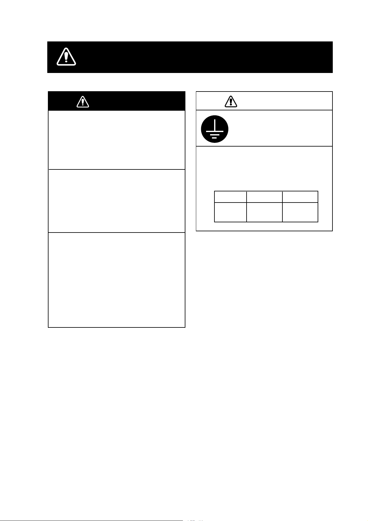
SAFETY INSTRUCTIONS
WARNING
Do not open the cover unless totally
familiar with electrical circuits and
service manual.
Improper handling can result in
electrical shock.
Turn off the power at the
switchboard before beginning the
installation.
Fire or electrical shock can result if the
power is left on.
Be sure that the power supply is
compatible with the voltage rating of
the equipment.
Connection of an incorrect power
supply can cause fire or equipment
damage. The voltage rating of the
equipment appears on the label above
the power connector.
CAUTION
Ground the equipment to
prevent mutual
interference.
Observe the following compass
safe distances to prevent
interference to a magnetic
compass:
Standard Steering
Display
unit
0.35 m 0.25 m
i
Page 4
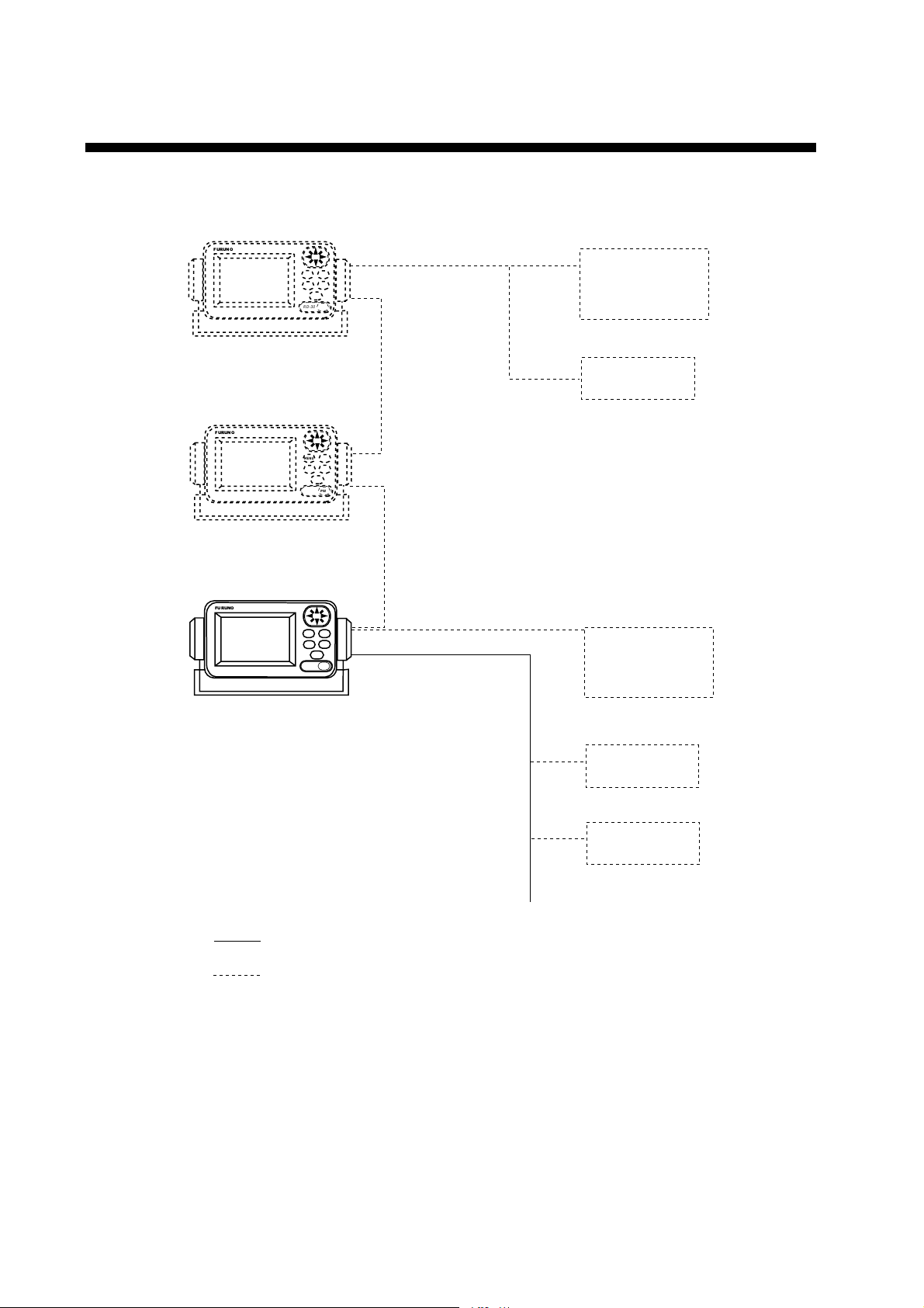
SYSTEM
FURUNO
Multi display
RD-30
FURUNO
Multi display
RD-30
CONFIGURATION
ENT
MENU
DIM
DISP
*
PWR
RD-30
ENT
MENU
DIM
DISP
*
PWR
RD-30
GPS receiver
GP-310B
Sensor
FURUNO
Multi display
RD-30
: Standard
: Option
ENT
MENU
DIM
DISP
*
PWR
RD-30
GPS receiver
GP-310B
Sensor
Navigator
Ship's mains
12-24 VDC
ii
Page 5
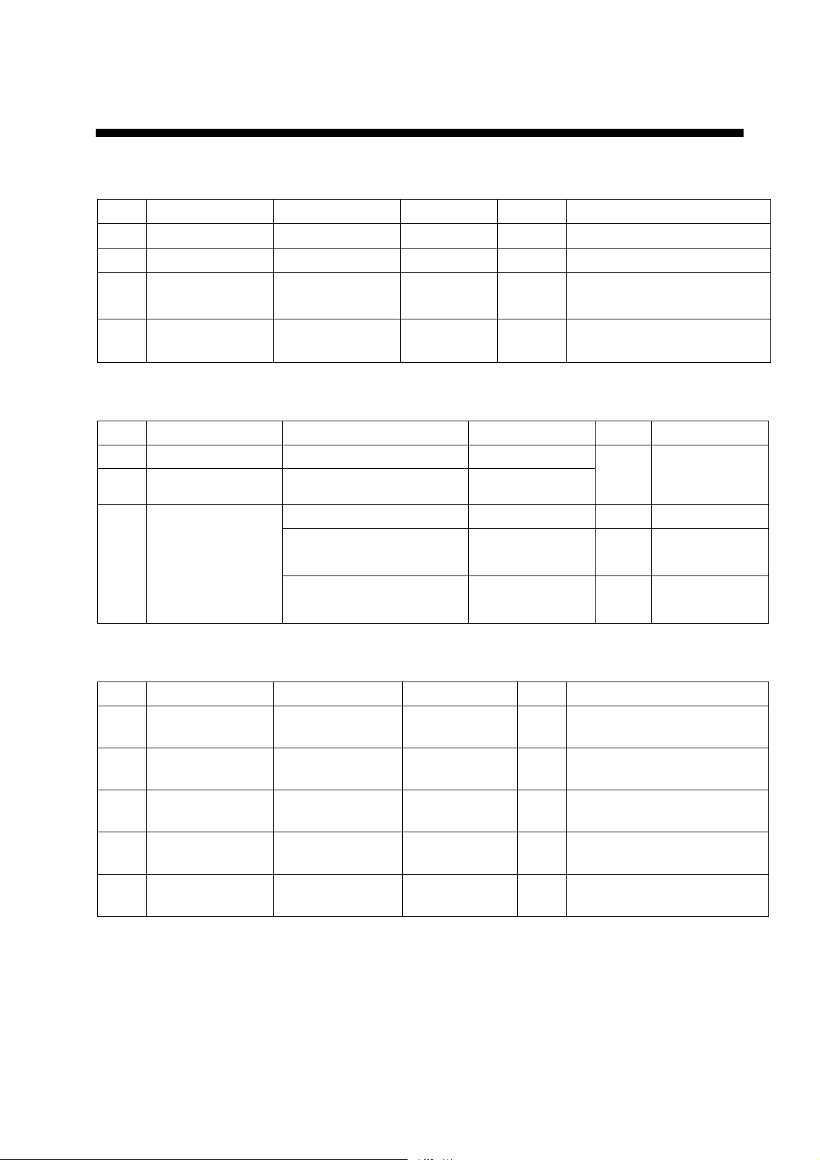
EQUIPMENT LIST
Standard supply
No. Name Type Code No. Qty Remarks
1 Multi Display RD-30 - 1
2 Spare Parts SP14-02901 - 1 set
3 Installation
Materials
4 Accessories FP14-02801 - 1 set Hard cover
CP14-06000 - 1 set +Tapping screw (4 pcs)
MJ-A7SPF0005-020
Optional supply
No. Name Type Code No. Qty Remarks
1 Flush Mount Kit S OP20-17 000-040-720
2 Flush Mount Kit F OP20-29 000-041-405
3 Cable Assy.
MJ-A7SPF0005-020 000-139-384 1 Power, signal
MJ-A7SPF0006-100 000-143-578 1 7P-7P
MJ-A7SPF/SRMD-100 000-144-534 1 7P-7P
1 For flush
mounting the
display unit
cross cable
straight cable
Sensors available
No. Name Type Code No. Qty Remarks
1 Smart Sensor 235DT-MSE 000-144-981 1 Depth & Temperature
Sensor
2 Smart Sensor 235DT-PSE 000-144-982 1 Depth & Temperature
Sensor
3 Smart Sensor 235DST-PWE 000-144- 9 83 1 Depth, S p ee d and
Temperature Sensor
4 Smart Sensor 235DHT-LMSE 000-144-984 1 Depth and High Precision
Temperature Sensor
5 Smart Sensor 235DHT-MSE 000-144-985 1 Depth and High Precision
Temperature Sensor
For technical specifications see Airmar’s technical data.
iii
Page 6

This page is intentionally left blank .
Page 7
1.
INSTALLATION
1.1 Installation of Display Unit
Mounting considerations
The display unit can be installed on a tabletop, on the overhead, or in a
panel (optional flush mounting kit required). Refer to the outline drawings
at the end of this manual for installation instructions. When selecting a
mounting location, keep in mind the following points:
• Locate the unit away from exhaust pipes and vents.
• The mounting location should be well ventilated.
• Mount the unit where shock and vibration are minimal.
• Locate the unit away from equipment which generates electromagnetic
fields such as a motor or generator.
• Allow sufficient maintenance space at the sides and rear of the unit and
leave sufficient slack in cables, to facilitate maintenance and servicing.
• Observe the following compass safe distances to prevent deviation of a
magnetic compass.
Standard compass, 0.35 m, Steering compass, 0.25 m.
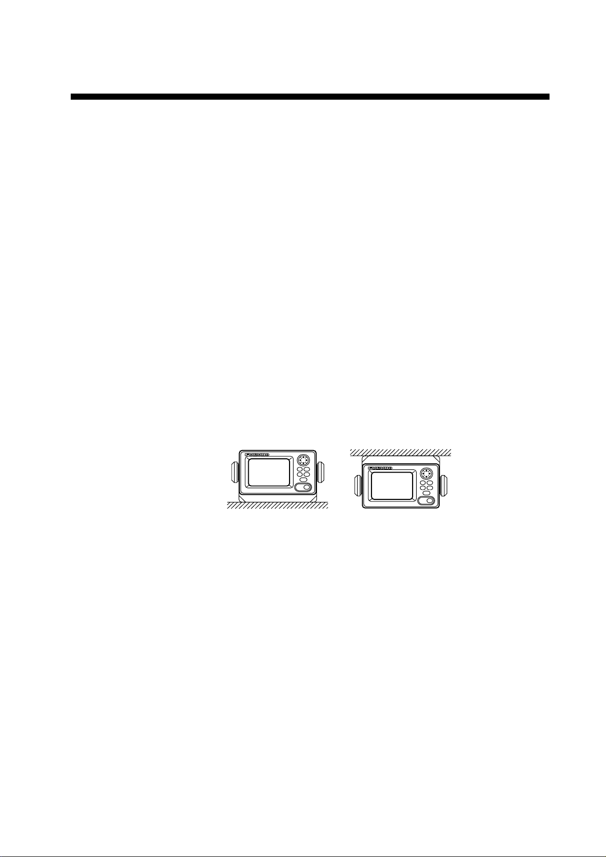
Tabletop and overhead mounting
Tabletop
Figure 1-1 Tabletop and overhead mounting methods
Overhead
1
Page 8

Flush mounting
There are two types of flush mount kits, F type and S type. For details, see
the outline drawings at the back of this manual.
F type
Flush mount kit F (Type: OP20-29, Code No.: 000-041-405)
No. Name Type Code No. Qty Remarks
1 Cosmetic Panel 20-016-1051 100-251-370 1
2 + Tapping Screw 5x20 SUS304 000-802-840 4
3 Hex Bolt M6x12 SUS304 000-862-127 2
4 Spring Washer M6 SUS304 000-864-260 2
1. Make a cutout of 183 X 92 mm.
2. Attach the cosmetic panel (supplied) to the display unit with hex bolts
(M6X12, supplied) and spring washers (M6, supplied).
3. Fix the display unit to the mounting location with four tapping screws
(5X20, supplied).
S type
Flush mount kit S (Type: OP20-17, Code No.: 000-040-720)
No. Name Type Code No. Qty Remarks
1 Fixing Metal 20-007-2401 100-183-190 2
2 Wing Bolt M4x30 YBSC2
MBN12
3 Hex Bolt M6x12 SUS304 000-862-127 2
4 Wing Nut M4 YBSC2
MBN12
5 Spring Washer M6 SUS304 000-864-260 2
1. Make a cutout of 167 X 92 mm.
2. Attach two fixing metals (supplied) to the display unit with hex bolts
(M6X12, supplied) and spring washers (M6, supplied).
3. Screw four wing bolts (supplied) into wing nuts (supplied).
4. Fasten the display unit to the mounting location with four sets of wing
bolts and nuts assembled at step 3.
000-804-799 4
000-863-306 4
2
Page 9

1.2 Wiring
The figure below shows where to connect cables on the rear of the display
unit.
GPS
RECEIVER
DISPLAY
UNIT
DISPLAY
UNIT
1A FUSE
(+ Line)
Black
POWER
(12-24 VDC)
-
+
Red
Ground
CAUTION
Ground the equipment to
prevent mutual interference.
Figure 1-2 Wiring
Note: The fuse holder contains a spring which fixes the fuse. To prevent
detachment of the spring, which would cause loss of power, tie the
line as shown in Figure 1-3.
Fuse holder
+ line (red)
Tie here.
Figure 1-3 How to fix spring in fuse holder
3
Page 10

Grounding
The display unit contains a CPU. While it is operating, it radiates noise,
which can interfere with radio equipment. Ground the unit as follows to
prevent interference:
• The ground wire should be 1.25 sq or larger.
• The ground wire should be as short as possible.
• The signal ground and frame ground are separated, however the power
line is not isolated. Therefore, do not connect the signal ground to the
frame ground when connecting other equipment to a positive ground
battery.
External equipment
The power supply port (IN/OUT port) is commonly used for connection of
external equipment such as navigation equipment or a PC. Refer to the
interconnection diagram on page S-1 for connection.
IN/OUT port
Connector Remarks
1TD-A
2TD-B
3 RD-H
4 RD-C
5+V
6GND
7FG
AUX port
Connector Remarks
1TD-A
2TD-B
3 RD-H
4 RD-C
5 +Vout
6GND
7FG
IEC61162-1/NMEA 0183
IEC61162-1/NMEA 0183
Power supply (1224VDC)
(INPUT)
IEC61162-1/NMEA 0183
IEC61162-1/NMEA 0183
Max 300 mA
(OUTPUT)
4
Page 11

One Display Unit
FURUNO
Two Display Units
FURUNO
No. 1
Ship's battery
12-24 VDC
MENU
DISP
RD-30
MENU
RD-30
ENT
DIM
*
PWR
AUX
ENT
DIM
DISP
IN/OUT
*
PWR
AUX
IN/OUT
NMEA 0183
POWER OUT
12-24 VDC
FURUNO
No. 2
Max. 20 m
Note2
MENU
DISP
RD-30
ENT
DIM
*
PWR
SENSOR
NMEA 0183
GP-310B
AUX
IN/OUT
Three Display Units
FURUNO
No. 1
Note1: A set of one GP-310B and three RD-30 can be powered with 12-24
Note2: For cable length up to 10 m use cable type MJ-A7SPF0006-100
AUX
ENT
MENU
DIM
DISP
IN/OUT
*
PWR
RD-30
Ship's battery
12-24 VDC
VDC power.
(cross cable), and for cable length 10-20 m use cable type MJ-
A7SPF0006-100 (cross cable) and MJ-A7SPF/SRMD-100 (straight
cable). Maximum length between the units is 20 m.
FURUNO
No. 2
Max. 20 m
Note2
MENU
DISP
RD-30
ENT
DIM
*
PWR
AUX
IN/OUT
FURUNO
No. 3
Max. 20 m
Note2
MENU
DISP
RD-30
ENT
DIM
*
PWR
GP-310B
AUX
IN/OUT
5
Page 12

Note3: Turn on display units in sequential order.
Note4: Refer to the following table to connect a sensor other than the GP-
310B. Do not exceed the maximum output current and the output
voltage range.
One RD-30 Two RD-30 Three RD-30
Ship’s
Battery
12 VDC 300 mA 10.0-14.9 V 180 mA 9.2-14.4 V 60 mA 8.7-14.1 V
24 VDC 300 mA 21.0-30.5 V 180 mA 20.4-30.2 V 60 mA 20.4-30.3V
Maximum
output
current
Fox example, in the three display units connection, a sensor with
maximum current 60 mA and input voltage range 8.7-14 .1 V or 20.4-30.3 V
can be connected.
Output
voltage range
Maximum
output
current
Output
voltage
range
Maximum
output
current
Output
voltage
range
6
Page 13

2. INITIAL SETTINGS
This equipment can input and output navigation data to external
equipment in IEC 61162-1 (NMEA 0183) format. Input data is output as
raw data. For output setting, refer to the operator’s manual of the
equipment.
2.1 Data Sentence Description
APB: Autopilot sentence data
BWC: Range and bearing to waypoint (great circle navigation)
BWR: Range and bearing to waypoint (rhumb line)
COG: Course over ground
DBK: Depth
DBS: Depth
DBT: Depth below transducer
DPT: Depth
GGA: GPS position fixing condition (time of fix, latitude, longitude,
receiving condition, number of satellites used, DOP)
GLC: Geographic position Loran-C
GLL: Latitude and longitude
GTD: Loran-C time difference
HDG: Heading, deviation and variation
HDM: Heading, magnetic north
HDT: Heading true
MDA: Wind direction and speed
MTW: Water temperature
MWV: Wind direction and speed
RMB: Generic navigational information (cross track error, steering
direction, starting waypoint no., destination waypoint no., latitude
and longitude of starting waypoint, latitude and longitude of
destination waypoint, range and bearing to waypoint, range and
bearing from present position to destination waypoint, velocity to
destination, arrival alarm)
RMC: Generic navigational information (UTC time, latitude, longitude,
ground speed, true course, day, month, year)
ROT: Rate of Turn
VBW: Water speed and ground speeds
VDR: Tidal current direction and current speed
VHW: Water speed and heading
VTG: Actual track and ground speeds
VWR: Relative wind direction and speed
VWT: Actual wind direction and speed
XTE: Course error amount and direction to steer
ZDA: UTC time (day, month, year)
7
Page 14

2.2 IEC 61162-1 (NMEA 0183) Input Data Sentences
The AUX port has priority when the same data sentences are input at it
and the IN/OUT port simultaneously.
> = Priority order
Position: GGA>RMC>GLL
Time: ZDA>GGA
Speed over ground: VTG>RMC>VBW
Speed through water: VHW>VBW
Wind speed, direction: True: MWV(T)>VWT>MDA
Water temperature: MTW>MDA
Depth: DPT>DBT >DBS >DBK
Course: VTG>RMC
Heading: HDT>HDG>HDM>VHW
Waypoint: RMB>BWR>BWC
Current set and drift: VDR
Atmospheric pressure: MDA (Bar>Inch, converted to hPa)
Humidity: MDA (True>Relative)
Cross-track error: XTE>APB>RMB
Time difference: GLC>GTD
Temperature: MDA
Rate of Turn: ROT
Apparent: MWV(R)>VWR
8
Page 15

2.3 Setting Input/Output
The I/O SETUP menu sets up the IN/OUT and AUX ports on the RD-30.
Additionally you can use this menu to output power to other display units,
in case of multiple display units.
Note: Note that the equipment can process data input at the rate of up to
430 characters/second. Some delay will occur when processing data
input at a higher rate.
1. Press the [MENU] key once or twice to open the main menu.
2. Select I/O SETUP and then press the [ENT] key.
I/O PORT SETUP
IN/OUT PORT : OFF
AUX PORT : OFF
POWER OUT : OFF
< SELECT SENTENCE >
IN/OUT PORT
AUX PORT
Figure 2-1 I/O PORT SETUP menu
3. Select IN/OUT PORT, AUX PORT or POWER OUT as appropriate and
then press the [ENT] key. One of the following displays appears
depending on your selection.
OFF
IN/OUT
IN/OUT and
AUX options
OFF
ON
POWER OUT
options
AUX
BOTH
OFF: No output
IN/OUT: Output data which is input through the IN/OUT port.
AUX: Output data which is input through the AUX port.
BOTH: Output mixed data which is input through the IN/OUT and AUX ports.
OFF:No output
ON: Outputs power to other display units
Figure 2-2 IN/OUT PORT, AUX PORT and POWER OUT options
Note: If, when BOTH is selected, the data sentence which has an
input interval faster than one second (ROT, HDT, etc.) is turned
on, some data may not be output.
4. Select appropriate option and then press the [ENT] key.
5. When OFF, IN/OUT or AUX is selected for the IN/OUT or AUX port, go
to step 8.
When “BOTH” is selected for IN/OUT or AUX port, select IN/OUT
PORT or AUX PORT of the SELECT SENTENCE and then press the
[ENT] key.
9
Page 16

IN/OUT PORT
AUX PORT
APB : OFF
BWC : OFFOFF
BWR : OFF
DBK : OFF
DBS : OFF
DBT : OFF
DPT : OFF
Number of sentences
currently turned on
00/08
APB : OFF
BWC : OFFOFF
BWR : OFF
DBK : OFF
DBS : OFF
DBT : OFF
DPT : OFF
00/08
Figure 2-3 IN/OUT PORT and AUX PORT menu
Note: Sentences currently being received are shown in reverse video.
6. Select sentence to output and then press the [ENT] key. Use or
to scroll the display.
OFF
ON
Figure 2-4 IN/OUT PORT and AUX PORT options
7. Select ON or OFF as appropriate and then press the [ENT] key. You
can turn ON up to eight sentences.
8. Press the [MENU] key twice to close the menu.
See the next page for examples of port settings.
10
Page 17

1
GP-310B
2
GP-310B
FURUNO
AUX
ENT
MENU
DIM
DISP
POWER
*
PWR
RD-30
IN/OUT
Ship's battery
12-24 VDC
IN/OUT: OFF
AUX: OFF
POWER OUT: ON
DEPTH
TEMPERATURE
AUX
ENT
MENU
DIM
DISP
*
PWR
RD-30
FURUNO
3
IN/OUT
DEPTH
TEMPERATURE
IN/OUT: AUX
AUX: IN/OUT
POWER OUT: OFF
L/L
L/L
L/L
GPS
PLOTTER
E/S
FURUNO
AUX
ENT
MENU
DIM
DISP
POWER
*
PWR
RD-30
IN/OUT
Ship's battery
12-24 VDC
IN/OUT: OFF
AUX: OFF
POWER OUT: ON
IN/OUT
AUX
MENU
DISP
*
RD-30
ENT
DIM
POWER
PWR
L/L
FURUNO
IN/OUT: AUX
AUX: OFF
POWER OUT: ON
L/L
4
FURUNO
AUX
ENT
MENU
DIM
DISP
POWER
*
PWR
RD-30
IN/OUT
Ship's battery
12-24 VDC
IN/OUT: OFF
AUX: AUX
POWER OUT: ON
5
FURUNO
AUX
ENT
MENU
DIM
DISP
*
PWR
RD-30
IN/OUT
Ship's battery
12-24 VDC
IN/OUT: BOTH
AUX: OFF
POWER OUT: ON
PLOTTER
L/L
GP-310B
L/L
L/L
L/L
LORAN C
PLOTTER
GPS
PLOTTER
FURUNO
AUX
MENU
RD-30
IN/OUT
L/L
ENT
DIM
DISP
L/L
*
PWR
L/L
IN/OUT: BOTH
AUX: IN/OUT
POWER OUT: ON
Note: For "BOTH," select sentences to
receive with "SELECT SENTENCE"
on the I/O SETUP menu.
FURUNO
AUX
ENT
MENU
DIM
DISP
*
PWR
RD-30
IN/OUT
L/L
DEPTH
IN/OUT: AUX
AUX: IN/OUT
POWER OUT: OFF
DEPTH
E/S
L/L
Figure 2-5 Example of I/O PORT SETUP
11
Page 18

PACKING LIST
C4413‑Z01‑C
A - 1
PACKING LIST
PACKING LISTPACKING LIST
RD-30
RD-30
RD-30RD-30
14CJ-X-9851 -4
1/1
N A M E
ユニット
ユニット UNIT
ユニットユニット
マルチディスプレイ
MULTIDISPLAY
予備品
予備品 SPARE PARTS
予備品予備品
ヒューズ
FUSE
付属品
付属品 ACCESSORIES
付属品付属品
保護カバー
COVER
工事材料
工事材料 INSTALLATION MATERIALS
工事材料工事材料
ケーブル組品MJ
CABLE ASSY.
+トラスタッピンネジ
UNIT
UNITUNIT
SPARE PARTS SP14-02901
SPARE PARTSSPARE PARTS
ACCESSORIES FP14-02801
ACCESSORIESACCESSORIES
INSTALLATION MATERIALS CP14-06000
INSTALLATION MATERIALSINSTALLATION MATERIALS
O U T L I N E
DESCRIPTION/CODE №
RD-30-E
000-041-574
FGMB 1A 125V
000-114-805
20-016-1091-2
100-297-032
MJ-A7SPF0009-020
000-145-612
5X20 SUS304 1シュ
**
SP14-02901
SP14-02901SP14-02901
FP14-02801
FP14-02801FP14-02801
CP14-06000
CP14-06000CP14-06000
Q'TY
1
2
1
1
+TAPPING SCREW
3.コ-ド番号末尾の[**]は、選択部品の代表コ-ド番号を表します。
CODE NUMBER ENDED BY "**" INDICATES THE NUMBER OF TYPICAL MATERIAL.
4
000-802-081
(略図の寸法は、参考値です。 DIMENSIONS IN DRAWING FOR REFERENCE ONLY.)
(略図の寸法は、参考値です。 DIMENSIONS IN DRAWING FOR REFERENCE ONLY.)
(略図の寸法は、参考値です。 DIMENSIONS IN DRAWING FOR REFERENCE ONLY.)(略図の寸法は、参考値です。 DIMENSIONS IN DRAWING FOR REFERENCE ONLY.)
Page 19

Page 20

Page 21

Page 22

外部センサー
Jan. 31, '03
S - 1
TD‑A
P
EXT. SENSOR
TD‑B
RD‑A
GPS受信機
GP‑310B
GPS RECEIVER
10m
*2 *3
MJ‑A7SPF/SRMD‑100
10m
ケーブル長:最大50m
CABLE LENGTH: MAX. 50m
RD‑B
P
MULTI DISPLAY
マルチディスプレイ
MJ‑A7SPFD
1
J2
AUX
TD‑A
TD‑A
IN/OUT
RD‑30
J1
1
*3
MJ‑A7SPFD
4
3
2
TD‑B
TD‑B
2
P
RD‑H
RD‑H
3
P
RD‑C
RD‑C
4
567
GND
Vout
+V
GND
567
FG
*1
IV‑1.25SQ
GND
FG
RD‑30
TITLE
マルチディスプレイ
相互結線図
名称
MULTI DISPLAY
NAME
INTERCONNECTION DIAGRAM
34
YEL
BLU
WHT
シロ
MJ‑A7SPF0005,2m
MJ‑A7SPFD
*3
1
J2
AUX
TD‑A
GRN
キ
アオ
ミドリ
P
P
ケーブル長:20mのとき
CABLE LENGTH: 20m
4
3
2
TD‑B
567
FG
RD‑H
GND
RD‑C
Vout
*1
IV‑1.25SQ
GND
MJ‑A7SPF/SRMD‑100
10m
*2 *3 *2 *3
10m
MJ‑A7SPF0006
*2
MJ‑A7SPF0006,10m
P
P
MJ‑A7SPFD
*3
J2
AUX
3
2
1
TD‑A
TD‑B
RD‑H
2
12‑24VDC
+V
P
RD‑C
4
GRN
GND
567
RED
BLK
TD‑A
TD‑B
FG
マルチディスプレイ
MULTI DISPLAY
IN/OUT
RD‑30
J1
*3
MJ‑A7SPFD
RD‑H
3
2
1
P
P
YEL
BLU
WHT
マルチディスプレイ
MULTI DISPLAY
TD‑A
TD‑B
IN/OUT
RD‑30
J1
*3
MJ‑A7SPFD
RD‑H
3
2
1
P
YEL
BLU
WHT
4
RD‑C
RD‑C
4
GRN
567
GND
Vout
DC OUT
300mA MAX
12‑24VDC
+V
GND
567
RED
BLK
kg
T.YAMASAKI
Y.KIMURA
Jan. 31 '03
APPROVED
MASS
SCALE
C4413‑C01‑ C
DWG.No.
FG
*1
IV‑1.25SQ
GND
Jan. 31 '03
CHECKED
DRAWN
FG
アカ
ミドリ
SENSOR
(+)
電源
クロ
FUSE(1A)
(‑)
SOURCE
12‑24 VDC
シロ
MJ‑A7SPF0009,2m
NMEA0183
アオ
NAV EQUIPMENT
B
キ
アオ
シロ
1
MJ‑A7SPF0009,2m
NMEA0183
NMEA0183
NAV EQUIPMENT
A
キ
NMEA0183
ミドリ
SENSOR
アカ
(+)
電源
クロ
FUSE(1A)
(‑)
*2. OPTION.
SOURCE
12‑24 VDC
注記
*1)造船所手配。
*2)オプション。
*3)コネクタは工場にて取付済み。
NOTE
*1. SHIPYARD SUPPLY.
*3. FITTED AT FACTORY.
C
 Loading...