

Page 1

OPERATOR'S MANUAL
REMOTE DISPLAY
MODEL
RD-20
www.furuno.co.jp
Page 2

Page 3

IMPORTANT NOTICES
General
• This manual has been authored with simplified grammar, to meet the needs of international users.
• The operator of this equipment must read and follow the descriptions in this manual. Wrong operation or maintenance can cancel the warranty or cause injury.
• Do not copy any part of this manual without written permission from FURUNO.
• If this manual is lost or worn, contact your dealer about replacement.
• The contents of this manual and equipment specifications can change without notice.
• The example screens (or illustrations) shown in this manual can be different from the screens
you see on your display. The screens you see depend on your system configuration and equipment settings.
• Save this manual for future reference.
• Any modification of the equipment (including software) by persons not authorized by FURUNO
will cancel the warranty.
• All brand and product names are trademarks, registered trademarks or service marks of their
respective holders.
How to discard this product
Discard this product according to local regulations for the disposal of industrial waste. For disposal
in the USA, see the homepage of the Electronics Industries Alliance (http://www.eiae.org/) for the
correct method of disposal.
How to discard a used battery
Some FURUNO products have a battery(ies). To see if your product has a battery(ies), see the
chapter on Maintenance. Follow the instructions below if a battery(ies) is used.
In the European Union
The crossed-out trash can symbol indicates that all types of batteries
must not be discarded in standard trash, or at a trash site. Take the
used batteries to a battery collection site according to your national
legislation and the Batteries Directive 2006/66/EU.
In the USA
The Mobius loop symbol (three chasing arrows) indicates that Ni-Cd
and lead-acid rechargeable batteries must be recycled. Take the used
batteries to a battery collection site according to local laws.
Ni-Cd Pb
In the other countries
Cd
There are no international standards for the battery recycle symbol. The number of symbols can
increase when the other countries make their own recycle symbols in the future.
i
Page 4

SAFETY INSTRUCTIONS
Indicates a condition that can cause death or serious
WARNING
CAUTION
Safety Instructions for the Operator Safety Instructions for the Installer
injury if not avoided.
Indicates a condition that can cause minor or moderate
injury if not avoided.
WARNING
Do not disassemble or modify the
equipment.
Fire, electrical shock or serious
injury can occur.
Turn off the power immediately if
water leaks into the equipment or
smoke or fire is coming from the
equipment.
Failure to turn off the equipment can
cause fire or electrical shock.
Contact a FURUNO agent for service.
Keep heater away from the
equipment.
Heat can change the equipment
shape and meltthe power cord, which
can cause fire or electrical shock.
WARNING
Turn off the power at the
switchboard before you install
the equipment.
Fire or electrical shock can occur if
the power is left on.
Be sure that the power supply is
compatible with the voltage rating
of the equipment.
Connection of an incorrect power
supply can cause fire or equipment
damage. The voltage rating of the
equipment appears on the label
above the power connector.
CAUTION
Ground the equipment to
prevent mutual interference.
CAUTION
Do not use the equipment for other
than its intended purpose.
Improper use of the equipment can
affect performance and void the
warranty.
Observe the following compass
safe distances to prevent
interference to a magnetic
compass:
Model
RD-20
RD-501 1.30 m 0.85 m
RD-502 1.00 m 0.65 m
Standard
compass
1.25 m 0.80 m
Steering
compass
ii
Page 5

TABLE OF CONTENTS
FOREWORD................................................................................................................ iv
SYSTEM CONFIGURATION........................................................................................ v
1. OPERATION.......................................................................................................... 1
1.1 Controls ......................................................................................................................1
1.2 How to Turn the Power On and Off............................................................................3
1.3 How to Adjust Display Brilliance................................................................................. 3
1.4 How to Select a Screen.............................................................................................. 4
1.5 How to Select the Units of Measurement ...................................................................8
1.6 How to Select the Display Mode.................................................................................8
1.7 How to Set the User Menu ....................................................................................... 10
2. MAINTENANCE, TROUBLESHOOTING................................................ ............ 12
2.1 Maintenance .............................................................................................................12
2.2 Life of the Parts ........................................................................................................13
2.3 Error Screens ...........................................................................................................13
2.4 Diagnostic Test.........................................................................................................13
2.5 Simulation Mode....................................................................................................... 15
2.6 Parts Location and Parts List.................................................................................... 16
3. INSTALLATION................................................................................................... 18
3.1 Equipment List..........................................................................................................18
3.2 Installation of Remote Display..................................................................................18
3.3 Installation of Remote Controller and Dimmer Controller.........................................20
3.4 Wiring .......................................................................................................................21
3.5 Adjustments..............................................................................................................26
3.6 JIS Cable Guide ....................................................................................................... 29
SPECIFICATIONS.................................................................................................. SP-1
PACKING LISTS .......................................................................................................A-1
OUTLINE DRAWINGS ..............................................................................................D-1
INTERCONNECTION DIAGRAM..............................................................................S-1
iii
Page 6

FOREWORD
A Word to the Owner of the RD-20 Remote Display
Congratulations on your choice of the FURUNO RD-20 Remote Display. We are confident you will
see why the FURUNO name has become synonymous with quality and reliability.
For over 60 years FURUNO Electric Company has enjoyed an enviable reputation for innovative
and dependable marine electronics equipment. This dedication to excellence is furthered by our
extensive global network of agents and dealers.
Your equipment is designed and constructed to meet the rigorous demands of the marine environment. However, no machine can perform its intended function unless properly installed and
maintained. Please carefully read and follow the operation and maintenance procedures set forth
in this manual.
We would appreciate feedback from you, the end-user, about whether we are achieving our purposes.
Thank you for considering and purchasing FURUNO equipment.
Features
The main features of the RD-20 are as shown below.
• Compact remote display features easy-to-view display with red LED.
• The navigation data in digital format with connection of various sensors.
• The size conforms to DIN (Deutsche Industrie Normen) standards, so there is uniformity among
the remote displays of other makers.
• Daisy chain connection is available for connecting a total of 10 RD-20s.
• When you connect multiple RD-20s, their display brilliances can be adjusted together.
Program Number
Program Number Initial Version
RD-20
Starter 2651003-01.xx Aug. 2009
Booter 2651004-01.xx Aug. 2009
Main 2651005-01.xx Aug. 2009
RD-501, RD-502
2651009-01.xx Aug. 2009
xx: minor change
iv
Page 7

SYSTEM CONFIGURATION
r
Single remote display
Remote display
RD-20
UNIT
MODE
RD-20
BRILL
FURUNO
PWR
DISP
12-24 VDC
NMEA0183
sensor signal
Remote controller
Environmental category:
Protected from weather: RD-20, RD-501, RD-502
FURUNO
DISP UNIT
MODE
REMOTE CONTROLLER
RD-501
RD-501
FURUNO
DAY
NT
BRILL
DIMMER CONTROLLER
RD-502
Dimmer controlle
RD-502
v
Page 8

SYSTEM CONFIGURATION
Multiple remote displays (daisy chain connection)
Pattern 1: Sensor signal and dimmer controller are commonly used. A total of 10 RD-20s
can be connected.
RD-20: A (main)
FURUNO
PWR
DISP
12-24 VDC
NMEA0183
sensor signal
RD-20
UNIT
MODE
BRILL
RD-20: B (sub) RD-20: C (sub) RD-20: D (main) RD-20: E (sub)
12-24 VDC
RD-501
FURUNO
DISP UNIT
MODE
REMOTE CONTROLLER
RD-501
RD-502: a
FURUNO
DAY
NT
BRILL
DIMMER CONTROLLER
RD-502
FURUNO
PWR
DISP
RD-20
UNIT
MODE
BRILL
FURUNO
PWR
DISP
RD-20
UNIT
MODE
BRILL
12-24 VDC
RD-501
FURUNO
DISP UNIT
REMOTE CONTROLLER
RD-501
MODE
DISP UNIT
Brilliance for RD-20 A, B and C are
controlled by RD-502 a.
Brilliance for RD-20 D and E are
controlled by RD-502 b.
12-24 VDC 12-24 VDC
RD-501
FURUNO
MODE
REMOTE CONTROLLER
RD-501
FURUNO
PWR
DISP
UNIT
MODE
RD-20
BRILL
RD-501
FURUNO
DISP UNIT
REMOTE CONTROLLER
RD-501
RD-502: b
FURUNO
DAY
NT
DIMMER CONTROLLER
RD-502
MODE
BRILL
FURUNO
PWR
DISP
RD-20
UNIT
MODE
BRILL
RD-501
FURUNO
DISP UNIT
MODE
REMOTE CONTROLLER
RD-501
Pattern 2: Dimmer controller is commonly used. A total of 10 RD-20s can be connected.
RD-20: main
FURUNO
PWR
DISP
12-24 VDC
NMEA0183
sensor signal
RD-20
UNIT
MODE
BRILL
RD-501
FURUNO
DISP UNIT
REMOTE CONTROLLER
RD-20: sub RD-20: sub RD-20: sub RD-20: sub
FURUNO
PWR
12-24 VDC
MODE
RD-501
RD-20
UNIT
DISP
MODE
BRILL
NMEA0183
sensor signal
FURUNO
PWR
DISP
12-24 VDC
RD-20
UNIT
MODE
BRILL
12-24 VDC 12-24 VDC
NMEA0183
sensor signal
RD-20
FURUNO
PWR
UNIT
DISP
MODE
NMEA0183
sensor signal
BRILL
RD-20
FURUNO
PWR
UNIT
DISP
MODE
NMEA0183
sensor signal
BRILL
RD-502
FURUNO
DAY
NT
BRILL
DIMMER CONTROLLER
RD-502
Note: When turning off the power for a RD-20 in the daisy chain connection, the RD-20s which
are connected after that RD-20 can receive neither the sensor signal nor the brilliance signal.
vi
Page 9

1. OPERATION
1.1 Controls
Remote display RD-20
RD-20
PWR DISP UNIT
2 3
1
No. Control Description
1 PWR Turn on/off the power.
2 DISP Switch the screen.
3 UNIT Select the units of measurement for the current screen.
4 MODE Select the mode for the current screen.
5 T, ST: Decrease the display brilliance.
S: Increase the display brilliance.
(See section 1.3 for details.)
How to remove the hard cover
MODE
4
5
Press here with thumb and
pull cover forward.
1
Page 10

1. OPERATION
Remote controller RD-501
2
1
DISP
REMOTE CONTROLLER
UNIT
RD-501
MODE
3
No. Control Description
1 DISP Switch the screen.
2 UNIT Select the units of measurement for the current screen.
3 MODE Select the mode for the current screen.
Dimmer controller RD-502
2
1
DAY
NT
BRILL
DIMMER CONTROLLER
RD-502
No. Control Description
1 DAY/NT Switch the display brilliance between daytime use and nighttime use.
2 T, ST: Decrease the display brilliance.
S: Increase the display brilliance.
2
Page 11

1. OPERATION
1.2 How to Turn the Power On and Off
Press the PWR key to turn on the power.
The start-up screen appears, showing all LED dots and 7-segments. Then, the model name, and
then the results of the ROM and RAM check, OK or NG (No Good), are shown. After the self-tests
are completed, the last-used display appears.
FURUNO
RD-20
8.8.8.8
LED test for dots
and 7-segments
Note: If all dots and 7-segments do not light, or if NG appears as the ROM and RAM check result,
contact your dealer.
To turn off the power, press the PWR key.
.
Model name
ROM
RAM
ROM/RAM test
OK
OK
1.3 How to Adjust Display Brilliance
To adjust the display brilliance, press T, S, or DAY/NT key. The setting range is 0 to 9. "0" is off
and "9" is the brightest.
Operation with main RD-20
The main RD-20 simultaneously controls the display brilliance of the main RD-20 and the sub
RD-20s.
• Controls with T key: Decrease the display brilliance.
• Controls with S key: Increase the display brilliance.
Operation with sub RD-20
When you want to individually adjust the display brilliance for each sub RD-20, do as follows:
• Controls with T key: Decrease the display brilliance. (The variation is smaller than that of the
main RD-20 and RD-502 connected to the main RD-20.)
• Controls with S key: Increase the display brilliance. (The variation is smaller than that of the
main RD-20 and RD-502 connected to the main RD-20.)
Operation with RD-502
The RD-502 simultaneously controls the display brilliance of the main RD-20 and the sub RD-20s.
• Controls with T key: Decrease the display brilliance.
• Controls with S key: Increase the display brilliance.
• Controls with the DAY/NT key: The display brilliance changes as shown in the table below with
every press of the key.
Current setting Setting after key operation Current setting Setting after key operation
00 59
15 62
26 73
37 84
48 95
3
Page 12
1. OPERATION
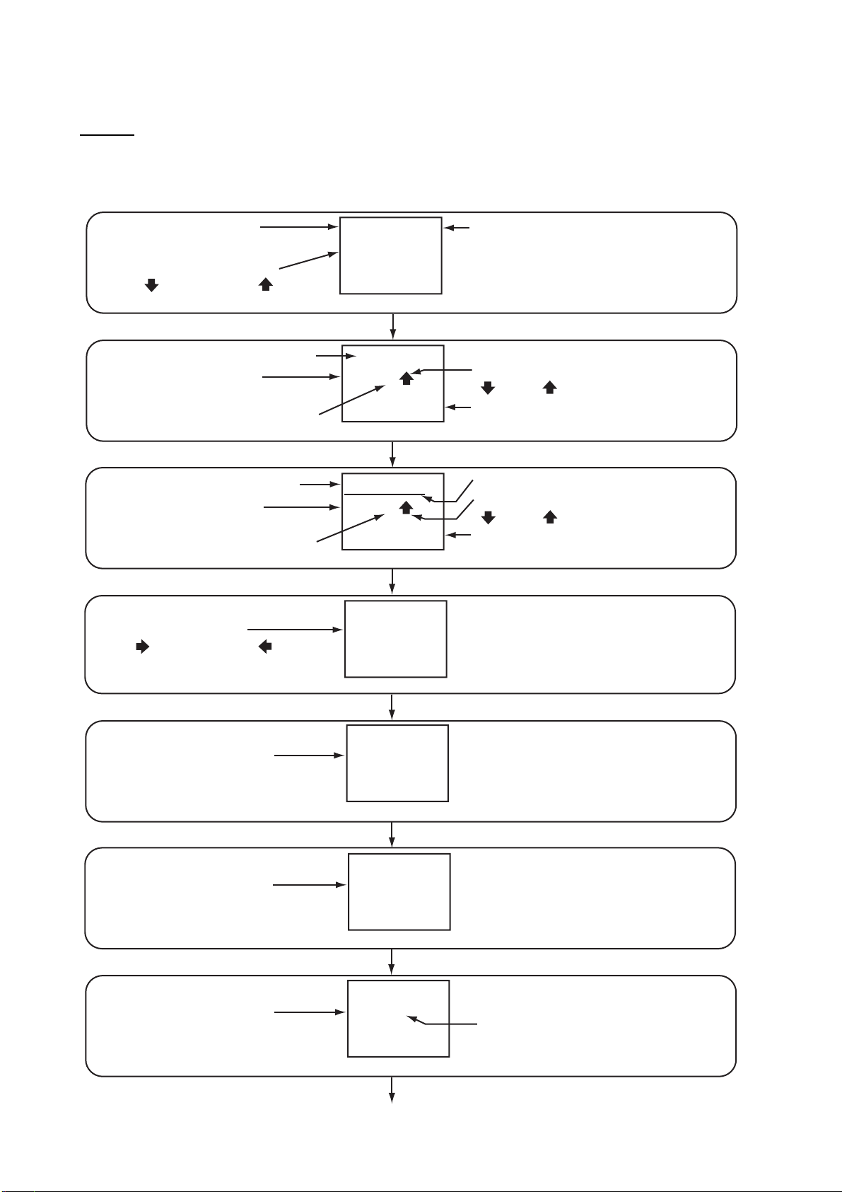
1.4 How to Select a Screen
Screen
The screen for the RD-20 changes as follows with the DISP key. When you start the RD-20, the
last-used screen appears. Availability of data depends on your system configuration.
Display mode
(AUTO, SOG, STW, GPS)
Direction of ship’s movement
(AFT or : After, FWD or : Forward)
Distance run
Display mode
(AUTO, SOG, STW, GPS)
“A” means AUTO mode.
Distance run
Display mode
(AUTO, SOG, STW, GPS)
“A” means AUTO mode.
Direction of ship’s turn
(S or : Starboard, P or : Port,
No indication: When 0.0 deg/min)
SOG
AFT
AUTO
kn
25.9
Speed (default)
DISP key
23456.7
SOG
N
M
kn
A
25.9
Distance since reset
DISP key
234567.8
SOG
N
M
kn
A
25.9
Total distance
DISP key
ROT
P
deg
/
min
10.6
Rate of turn
DISP key
AUTO appears when display
mode is “AUTO”.
Direction of ship’s movement
( : After, : Forward)
Speed
Underline for total distance screen
Direction of ship’s movement
( : After, : Forward)
Speed
Display mode
(No indication: True,
MAG: Magnetic)
Display mode
(No indication: True,
MAG: Magnetic)
Course over the ground
Display mode
(AUTO, DBK, DBT, DBS)
HDG
MAG
deg
135.4
Heading
DISP key
COG
MAG
deg
132.9
DISP key
DEPTH
DBK
A
m
198.5
Depth
DISP key (cotinued on next page)
“A” means AUTO mode.
4
Page 13

(Continued from previous page)
1. OPERATION
Direction of ship’s turn
(STBD or : Starboard side,
PORT or : Port side,
No indication: When 0.0 or 180.0 deg)
Direction of ship’s turn
(STBD or : Starboard side,
PORT or : Port side,
No indication: When 0.0 or 180.0 deg)
Display mode
(ENGINE or SHAFT)
Direction of ship’s movement
(AH or
: Ahead, AS or -: Astern)
+
Engine/Shaft revolution or Propeller pitch (Select in the user menu.)
Display mode
(T: Theoretical,
R: Relative)
Display mode
(T: Theoretical, PORT: The wind
blows from the port (relative),
STBD: The wind blows from the
starboard (relative), No indication:
When 0.0 or 180.0 deg)
RUDDER
STBD
9.4
Rudder angle
ORDER
STBD
9.4
Rudder angle order
ENGINE
+
3
RPM
150
or
WIND
T
3.1
Wind speed and direction
WIND
T
84.5
Wind direction
P
deg
DISP key
P
deg
DISP key
PITCH
+
DISP key
SPD
kn
DISP key
DIR
deg
DISP key
Current rudder position
(S: STBD (starboard),
P : PORT,
No indication: SINGLE)
Current rudder position
(S: STBD (starboard),
P : PORT,
No indication: SINGLE)
2
%
Number of engine, shaft
or propeller (When 0 is
selected, no indication.)
36
Theoretical: Theoretical
or calculated wind. Wind
direction relative to the
ship’s bow, wind speed
as if the ship is stationary.
Relative: Relative or
apparent wind. Wind
direction relative to the
ship’s bow, wind speed
relative to a moving vessel.
WATER
TEMP
°
C
41.0
Water temperature
DISP key
Go to the Speed screen.
Note: Settings are saved six seconds after you change settings. If you turn off the power right after
you change settings, the last settings are not saved.
5
Page 14

1. OPERATION
List of terms
The following table shows the terms used in the RD-20.
Term Meaning
% Percent
°C Degree(s) Celsius
°F Degree(s) Fahrenheit
1AXIS 1-axis
7-SEG 7-Segment
38.4k 38.4Kbps
4.8k 4.8Kbps
A, AUTO Automatic
AFT After
AH Ahead
ALL All
ARROWS Arrows
AS Astern
AVE Average
BACK Back
BAUD-RATE Baud rate
BOOTER Booter
BRILL Brilliance
CAL Calibration
CH1 Serial Input port, “Channel 1” (RD1A, RD1B)
CH2 Serial Input/Output port, “Channel 2” (RD2A, RD2B, TD2A, TD2B)
ChkSUM Check Sum
CLEAR Clear
COG Course Over the Ground
DATA Data
DAY Daytime
DBK Depth Below Keel
DBS Depth Below Surface
DBT Depth Below Transducer
deg/min degree/minute
DEPTH Depth
DIMMER Dimmer
DIR Direction
DISP Display
DOT Dot-Matrix
ENGINE Engine
ft feet
FWD Forward
GPS Global Positioning System
HDG Heading
KEY Key
km/h Kilometer/hour
kn knot
LED Light Emitting Diode
LOOP Loop
MAG Magnetic: The bearing measured with magnetic north as the reference direction.
MAIN Main
6
Page 15

1. OPERATION
Term Meaning
MENU Menu
mph Miles per hour
m/s Meter/second
NG No Good
NM Nautical Mile
No. Number
NO No
NT Night
OFF Off
OFFSET Offset
OK OK
ON On
ORDER Rudder Angle Order
OUT Output
PITCH Propeller Pitch
P, PORT Port/Port Side
PWR Power
R Relative: Relative or apparent wind. The wind direction relative to the ship’s bow
and the wind speed relative to the moving vessel.
RAM Random Access Memory
RANK Rank of Dot-Matrix LED
ROM Read Only Memory
ROT Rate of Turn
RPM Revolutions Per Minute
RUDDER Rudder/Rudder Angle
SAVE Save
SELECT Select
SET Set
SHAFT Shaft
SIM Simulation
SINGLE Single
S-OUT Sensor Out
SPEED, SPD Speed
SOG Speed Over the Ground
STARTER Starter
STW Speed Through the Water
S, STBD Starboard/Starboard Side
SUB Sub
SYS System
T Theoretical: Theoretical or calculated wind. The wind direction relative to the
ship’s bow and the wind speed as if the ship is stationary.
TEMP Temperature
TEST Test
TEXT Text
TIME Time
UNIT Unit
VECTOR Vector
WATER Water
WIND Wind
YES Yes
7
Page 16

1. OPERATION
1.5 How to Select the Units of Measurement
You can select the units of measurement for speed, distance, depth, wind speed and water temperature.
1. Press the DISP key to display the screen which you want to change the units of measurement.
2. Press the UNIT key to select the unit desired.
• Speed: kn (default), m/s, km/h
• Depth: ft (default), m, fm
• Wind speed: kn (default), m/s, km/h, mph
• Water temperature: °C (default), °F
• Distance: The combinations of the units for distance and speed are as follows:
Distance Speed Remarks
NM kn Default
NM m/s
km m/s
km kn
1.6 How to Select the Display Mode
1. Press the DISP key to display the screen which you want to change the display mode.
2. Press the MODE key to select the display mode desired.
• Speed: AUTO (default), SOG, STW, GPS
In the [AUTO] mode, speed data is displayed in order of priority, SOG, STW and GPS. The
SOG has the highest and GPS has the lowest priority. That is, when SOG, STW and GPS
data are input, the SOG data is displayed. "AUTO" appears at the upper-right corner of the
screen when the [AUTO] mode is active.
Display mode
(SOG: Speed over the ground,
STW: Speed through the water,
GPS: Speed data from the GPS)
SOG/STW: The speed data from the doppler sonar, doppler log, speed log, etc.
GPS: The data from the navigation equipment not described above (mainly, SOG data from
a GPS navigator)
SOG
AUTO
AFT
10.8
kn
“AUTO” indication
• Distance: AUTO (default), SOG, STW, GPS
In the [AUTO] mode, the highest priority data is SOG and the lowest is GPS. "A" appears
after the display mode when the [AUTO] mode is active.
N
M
kn
A
“A” means AUTO mode.
Display mode
234567.8
SOG
25.9
8
Page 17

1. OPERATION
• Heading: True (default, display indication: none), Magnetic (display indication: "MAG")
HDG
Display mode
(No indication: True,
MAG: Magnetic)
• Course over the ground: True (default, display indication: none), Magnetic (display indication: "MAG")
Display mode
(No indication: True,
MAG: Magnetic)
• Depth: AUTO (default), DBK, DBT, DBS
In the [AUTO] mode, the highest priority data is DBK and the lowest is DBS. "A" appears
after the display mode when the [AUTO] mode is active.
MAG
135.4
COG
MAG
30.9
deg
deg
Display mode
(DBK: Depth below keel,
DBT: Depth below transducer,
DBS: Depth below surface)
• Engine/shaft revolution: Select [ENGINE] or [SHAFT] from the user menu. The screen
shows "ENGINE" or "SHAFT" depending on your selection.
Display mode
(ENGINE or SHAFT)
DEPTH
DBK
A
ft
198.5
ENGINE
+
3
RPM
“A” means AUTO mode.
Revolution per minute
150
• Propeller pitch: Select [PITCH] from the user menu. "PITCH" appears on the screen.
Display mode
PITCH
+
2
%
36
• Wind speed: Theoretical (default, display indication: "T"), Relative (display indication: "R")
Display mode
(T: Theoretical,
R: Relative)
WIND
T
SPD
kn
3.1
• Wind direction: Theoretical (default, display indication: "T"), Relative (When the wind blows
from the port, "PORT" is displayed. When the wind blows from the starboard, "STBD" is displayed. When the wind direction is 0.0 or 180.0 degrees, there is no indication of "PORT"
nor "STBD".)
Display mode
(T: Theoretical,
PORT/STBD/no indication: Relative)
WIND
T
84.5
DIR
deg
9
Page 18

1. OPERATION
1.7 How to Set the User Menu
The user menu lets you adjust the RD-20 to meet your needs.
No. Menu Description Setting Default
1 KEY LED BRILL Set the brilliance for key LED. 1 to 8 8
2 RPM SET ENGINE
(or SHAFT, PITCH)
3 RPM SET No. Select the number of engine, shaft, or
4 WIND AVE TIME Set the wind averaging time to smooth
5 RUDDER SINGLE (or
STBD, PORT)
6 Direction ARROWS
(or TEXT)
7 DOT LED CAL If there is a difference between the dot8 7-SEG LED CAL -3 to 3 0
Select the engine-related data to show
from [ENGINE], [SHAFT], or [PITCH].
propeller.
wind data. The longer the setting, the
more the data is smoothed. To find the
momentary wind direction and speed, select the shorter time.
Select the mounting location of the rudder from [SINGLE], [STBD] (starboard),
or [PORT].
Select the indication of direction from
[ARROWS] or [TEXT] for speed, ROT
(rate of turn), rudder and engine/shaft/
pitch.
matrix LED brilliance and the 7-segment
LED brilliance, adjust the DOT LED CAL
or 7-SEG LED CAL so that both brilliances are the same. -3 is the darkest and 3
is the brightest.
ENGINE,
SHAFT,
PITCH
0 to 9 0
0, 1, 2, 3,
5, 10 min
SINGLE,
STBD,
PORT
ARROWS,
TEXT
-3 to 3 0
ENGINE
1 min
SINGLE
ARROWS
Setting procedures
1. While you hold down the DISP key, press the PWR key to turn on the power.
2. Press the MODE key or the UNIT key to select the screen desired.
3. Press T or S key to set the value then press the MODE key to save the data and go to the
next screen.
4. After you set all options, the screen for saving data appears. Press the MODE key to save the
data. The equipment restarts.
Note: The user menu is inoperative on the RD-501 and RD-502.
10
Page 19

1. OPERATION
KEY
BRILL
LED
1
Set the brilliance for key LED
using
or key
8
UNIT key
2
Select an item to display among [ENGINE], [SHAFT], or [PITCH].
RPM
SET
ENGINE
key key
RPM
SHAFT
key
UNIT key
RPM
No.
UNIT key
WIND
TIME
UNIT key
5
Select the mounting location of rudder.
RUDDER
SINGLE
key key
RUDDER
STBD
key
UNIT key
6
Select the indication of direction.
Direction
ARROWS
UNIT key
key
key
MODE key
SET
MODE key
SET
0
MODE key
AVE
1
MODE key
MODE key
Direction
TEXT
MODE key
RPM
SET
PITCH
3
Select the number of
engine, shaft or propeller
using
or key
4
Set the wind average
processing time (min)
using
or key
RUDDER
PORT
.
.
.
Dot-matrix
Segment
DOT
LED
CAL
0
UNIT key
7-SEG
CAL
MODE key
LED
0
UNIT key
SAVE DATA
YES
The equipment restarts.
MODE key
MODE
MODE key
11
7
Adjust the dot-matrix
LED brilliance using
or key
8
Adjust the 7-segment
LED brilliance using
or key
Confirmation for
saving data
.
.
Page 20

2. MAINTENANCE, TROUBLESHOOTING
NOTICE
Do not apply paint, anti-corrosive
sealant or contact spray to coating
or plastic parts of the equipment.
Those items contain organic solvents
that can damage coating and plastic
parts, especially plastic connectors.
2.1 Maintenance
Check the following points regularly to maintain performance:
• Check that connections on the rear panel are firmly tightened and free of dust.
• Check that the ground system is free of rust and the ground wire is tightly fastened.
• Remove dust or dirt from the cabinet with a soft, dry cloth. For stubborn dirt, you can use water-
diluted mild detergent. Clean the cabinet with a dry cloth after you use detergent. Do not use
solvents like thinner, acetone or benzene to clean the unit. They can remove paint and indications.
12
Page 21

2. MAINTENANCE, TROUBLESHOOTING
2.2 Life of the Parts
Fuse replacement
The fuse in the remote display protects the equipment from overcurrent and equipment fault. If the
fuse blows, find the cause before you replace the fuse. Use the correct fuse. A wrong fuse can
damage the equipment. See the outline drawings about the location of the fuse.
WARNING
Use the correct fuse.
A wrong fuse can damage the equipment
and cause fire.
Type Code No. Remarks
FGMB 125V 2A PBF 000-157-479-10 12-24 VDC
LED life
The life of the LED is approximately 46,000 hours. The actual number of hours depends on ambient temperature and humidity. The consumption current depends on the number of lighting
LEDs and the LED brilliance.
2.3 Error Screens
When the NMEA sentences are not input or are timed out, the RD-20 displays the following error
screens.
RUDDER
---
Example: Rudder
angle
P
deg
-
.
SPEEDAUTO
kn
--.-
Example: Speed
in [AUTO] mode
DEPTH
DBK
---
Example: Depth
in not [AUTO]
mode
ft
-
.
------
GPS
A
--.-
Example: Total
distance in
[AUTO] mode
N
-
.
M
kn
2.4 Diagnostic Test
The diagnostic test checks the system for correct operation. There are two types of diagnostic
tests; automatic test and key test.
Automatic test
1. While you hold down the UNIT key, press the PWR key to turn on the power.
2. Press the MODE key. The automatic test starts. To stop the test, press the PWR key.
Note: You can extend the display time for a screen by three seconds. Momentarily press any
key (except the PWR key) at the desired screen during the test. You can do this procedure up
to 10 times, that is you can extend the display time to a maximum of 30 seconds.
13
Page 22

2. MAINTENANCE, TROUBLESHOOTING
While holding down the UNIT key,
press the PWR key to turn on the power.
SELECT
Start screen for
automatic test
MODE key (Automatic test starts.)
AUTO
FURUNO
Model name
LED test
pattern 1
RD-20
8.8.8.8
LED test
pattern 2
8.8.8.8
ROM/RAM test
ROM
RAM
OK
OK
LOOPBACK
Serial loopback
test for CH2*
Serial loopback
test for CH1*
*: When loopback test
is OK, “OK” appears.
When loopback test is
NG, there is no indication.
CH2
LOOPBACK
CH1
RD-502
2651009-
.
**: When connecting
RD-501 or RD-502,
program number and
version number are
displayed.
xx.xx
RD-501
2651009-
.
xx.xx
RD-502 program
version**
RD-501 program
version**
MAIN
2651005-
Main program
version
xx.xx
STARTER
Starter program
version
2651003-
xx.xx
xx: Program version number
Test results
• Model name: The model name "RD-20" is displayed.
• LED test (pattern 1 and 2): Check that all LED segments light.
• ROM, RAM: The results of the ROM/RAM test are displayed as OK or NG (No Good). If any NG
is displayed, contact your dealer for instruction.
• Program version (starter, booter, main, RD-501, RD-502): The program version numbers are
displayed.
• Serial loopback test (CH1 and CH2), for field serviceman: A test jumper is required for this test.
The result of the loopback test is displayed as OK or no indication (test not done).
Key test
1. While you hold down the UNIT key, press the PWR key to turn on the power.
2. Press T key once to display the key test screen.
Note: You can not use the T key of the RD-502 at this screen.
BOOTER
2651004-
xx.xx
Booter program
version
14
Page 23

2. MAINTENANCE, TROUBLESHOOTING
3. Press the MODE key.
4. Press each key except the PWR key. You can test up to 10 keys. The key name for the key
pressed and the number of keys remaining to test are displayed. When the count is 0, the start
screen for the key test appears. When testing more than 10 keys, repeat steps 3 and 4.
While holding down the UNIT key,
press the PWR key to turn on the power.
SELECT
Start screen for
automatic test
AUTO
key
SELECT
Start screen for
key test
KEYTEST
MODE key
KEYTEST
10
Any key (for example,
KEYTEST
DISP
5. To stop the test, press the PWR key.
Note: For the remote controller and dimmer controller, "-R" is displayed after the key name except
the DAY/NT key.
2.5 Simulation Mode
The simulation mode, which shows internally generated navigation data, is provided to acquaint
you with the features of the RD-20. "SIM" appears and flashes at the upper-right corner of the
screen when the simulation mode is turned on.
SOG
AFT
DISP key)
9
Any key
SIM
kn
The indication
“SIM” appears.
KEY TEST
UNIT
0
(for example,
UNIT key)
10.8
1. While you hold down the UNIT key, press the PWR key to turn on the power.
2. Press T key twice. The screen for simulation appears.
Note: You can not use the T key of the RD-502 at this screen.
3. Press the MODE key to start the simulation mode.
4. To stop the simulation mode, press the PWR key to turn off the power.
15
Page 24

2. MAINTENANCE, TROUBLESHOOTING
2.6 Parts Location and Parts List
Parts Location
RD-20
26P0009
RD-501/502
Rear side
26P0009
26P0008
Cover opened
RD-501: 26P0012A
RD-502: 26P0012B
Cover opened
16
Page 25

Parts List
2. MAINTENANCE, TROUBLESHOOTING
ELECTRICAL PARTS
PRINTED CIRCUIT BOARD Code No.
26P0008, PNL
26P0009, MAIN
ELECTRICAL PARTS
PRINTED CIRCUIT BOARD Code No.
26P0012A, RMT
ELECTRICAL PARTS
Model
Unit Remote display RD-20
-
-
Model
Unit Remote controller RD-501
-
Model
Unit Dimmer controller RD-502
RD-20
RD-501
RD-502
PRINTED CIRCUIT BOARD Code No.
26P0012B, RMT
-
17
Page 26

3. INSTALLATION
3.1 Equipment List
Standard supply
Name Type Code No. Qty Remarks
Remote Display RD-20 - 1
Installation Materials CP26-01001* 001-076-460-00 1
Accessories FP26-00301* 001-076-470-00 1
Spare Parts SP26-00101* 001-076-450-00 1
Optional supply
Name Type Code No. Remarks
Remote Controller RD-501 - Including CP26-01101*
Dimmer Controller RD-502 - Including CP26-01201*
Hanger OP26-1* 000-016-195-00
*: See the Packing lists.
3.2 Installation of Remote Display
Mounting considerations
The remote display can be installed on a desktop, on the overhead, or flush mounted in a panel.
When you select a mounting location, keep in mind the following points:
• The nominal viewing distance for the display unit is 2.0 m. Select a suitable mounting location
considering that distance.
• Locate the unit away from exhaust pipes and vents.
• Locate the unit out of direct sunlight.
• Select an installation location that is well ventilated.
• Mount the unit where shock and vibration are minimal.
• Locate the unit away from equipment which generates the electromagnetic fields like a motor
or generator.
• Allow enough maintenance space at the sides and rear of the unit. Leave enough slack in cables to facilitate maintenance and servicing.
• Observe the compass safe distances (see page ii) to prevent interference to a magnetic compass.
18
Page 27

3. INSTALLATION
Flush mounting
1. Make a cutout in the mounting location (132 mm (width) x 120 mm (height)).
2. Make four pilot holes for self-tapping screws (diameter: 3 mm) in the location indicated in the
illustration below.
3. Insert the sponge to the remote display from the rear side.
4. Set the remote display to the cutout and fasten the remote display with four self-tapping
screws (M3x15).
5. Set a cosmetic cap to each fixing screw on the front panel. (See “How to set the cosmetic cap”
on page 20.)
131 ± 0.5 (5.16”)
132 ± 1.0 (5.20”)
131 ± 0.5 (5.16”)
Pilot hole for
self-tapping screw
144 (5.67”)
131 ± 0.5 (5.16”)
144 (5.67”)
131 ± 0.5 (5.16”)
120 ± 1.0 (4.72”)
Fixing hole (4-φ4)
for self-tapping screw
12 (0.47”)
74 (2.91”)
104 (4.09”)
Note: If it is more convenient to connect cables before you install the remote display, first connect the cables referring to the section 3.4.
Desktop or overhead mounting
You can mount the remote display on a desktop or on the overhead using the optional hanger
(Type: OP26-1, Code No.: 000-016-195-00).
1. Insert the hanger mounting plate to the remote display from the rear and fasten the hanger
mounting plate from the front of the remote display with four binding head screws (M3x12).
2. Fix the bottom of the hanger to the mounting location with four self-tapping screws (4x16).
3. Insert a washer to each knob (right and left) and fix the knobs to the remote display loosely.
4. Slip the screw parts of the knobs to the slit of the hanger and set the remote display to the
hanger.
5. Tighten the knobs to fasten the hanger to the remote display.
6. Set a cosmetic cap to each fixing screw on the front panel. (See “How to set the cosmetic cap”
on page 20.)
Washer
Binding
head screw
Knob
Hanger mounting plate
Hanger
19
Page 28

3. INSTALLATION
How to set the cosmetic cap
Set a cosmetic cap to each fixing screw on the front panel as shown below.
Set cosmetic cap to hole so cap is flush with panel.
3.3 Installation of Remote Controller and Dimmer Controller
The optional remote controller RD-501 and dimmer controller RD-502 can be flush mounted in a
panel. The size and the mounting procedure are shared by RD-501 and RD-502. For the mounting
location, refer to the mounting considerations for the remote display in section 3.2.
Flush mounting
1. Make a cutout in the mounting location (88 mm (width) x 76 mm (height)).
2. Make four holes of φ4 in the location indicated in the illustration below.
3. Set the remote controller or dimmer controller to the cutout. Insert four binding head screws
(M3x12) from the front side then fasten the unit with four sets of flat washers, spring washers
and hexagonal nuts from the rear side.
88 ± 1.0 (3.46”)
DISP
UNIT
MODE
86 ± 0.5 (3.39”)
76 ± 1.0 (2.99”)
86 ± 0.5 (3.39”)
Fixing hole (4-φ4)
REMOTE CONTROLLER
RD-501
Note: If it is more convenient to connect cables before you install the remote controller or dimmer controller, first connect the cables referring to the section 3.4.
20
Page 29

3.4 Wiring
Interconnection
Refer to the interconnection diagram (page S-1) to connect cables.
Single remote display
Remote display RD-20
12 11 10
9 8 7 6 5 4 3 2 1
12-24 VDC
Sensor signal
+
11
-
12
DPYC-1.5
TTYCS-1 (max. 100 m)
3. INSTALLATION
4
φ
Ground
terminal
Dimmer controller
RD-502
9 8 7 6 5 4 3 2 1
Signal
TD2A
TD2B
Vin
GND
RD-502 RD-501
1 6
2 7
3 8
4 9
TTYCS-4
RD1A
RD1B
Remote controller
RD-501
9 8 7 6 5 4 3 2 1
Signal
RD2A
RD2B
Vout
GND
7
8
Signal
Vin
GND
TD2A
TD2B
4
φ
TTYCS-4
RD-501 RD-20
3 1
4 2
1 3
2 4
IV-1.25sq
To ground terminal
on hull
Signal
Vout
GND
RD2A
RD2B
21
Page 30

3. INSTALLATION
RD-501
RD-502: a
RD-20: A
(Dimmer main)
12-24 VDC
NMEA0183 sensor signal
12-24 VDC
RD-501
RD-20: B
(Dimmer sub)
RD-20: C
(Dimmer sub)
RD-20: D
(Dimmer main)
RD-20: E
(Dimmer sub)
12-24 VDC
RD-501
Multiple remote displays (daisy chain connection)
Pattern 1: Sensor signal and dimmer controller are commonly used. A total of 10 RD-20s
can be connected in a daisy chain. A maximum of nine sub RD-20s can be connected.
NMEA0183 sensor signal
NMEA0183 sensor signal
12-24 VDC
12-24 VDC
RD-20: A
RD-20: A
(Dimmer main)
(Dimmer main)
RD-20
FURUNO
PWR
UNIT
DISP
MODE
BRILL
RD-501
RD-501
FURUNO
DISP UNIT
MODE
REMOTE CONTROLLER
RD-501
RD-502: a
DAY
NT
DIMMER CONTROLLER
RD-502: a
FURUNO
BRILL
RD-502
RD-20: B
RD-20: B
(Dimmer sub)
(Dimmer sub)
RD-20
FURUNO
PWR
UNIT
DISP
MODE
BRILL
12-24 VDC
12-24 VDC
RD-501
RD-501
FURUNO
DISP UNIT
REMOTE CONTROLLER
RD-501
MODE
RD-20: C
RD-20: C
(Dimmer sub)
(Dimmer sub)
RD-20
FURUNO
PWR
UNIT
DISP
MODE
12-24 VDC
12-24 VDC
FURUNO
DISP UNIT
REMOTE CONTROLLER
RD-501
Brilliance for RD-20 A, B and C is
controlled by RD-502 a.
BRILL
RD-501
RD-501
MODE
RD-20: E
RD-20: D
RD-20: D
(Dimmer main)
(Dimmer main)
RD-20
FURUNO
PWR
UNIT
DISP
MODE
BRILL
12-24 VDC 12-24 VDC
RD-20: E
(Dimmer sub)
(Dimmer sub)
RD-20
FURUNO
PWR
UNIT
DISP
MODE
RD-501
FURUNO
DISP UNIT
REMOTE CONTROLLER
RD-501
MODE
FURUNO
DISP UNIT
REMOTE CONTROLLER
RD-501
RD-502: b
FURUNO
DAY
NT
DIMMER CONTROLLER
RD-502
Brilliance for RD-20 D
BRILL
and E is controlled by
RD-502 b.
BRILL
RD-501
MODE
DC
Sensor
Remote display RD-20
(Dimmer main)
12 11 10
9 8 7 6 5 4 3 2 1
FURUNO
DAY
RD-502
NT
BRILL
DIMMER CONTROLLER
RD-502
Signal
TD2A
TD2B
12 11 10
DC
TTYCS-1 (max. 30 m)
FURUNO
DISP UNIT
MODE
REMOTE CONTROLLER
RD-501
RD-501
RD-20 (main) RD-20 (sub)
5 7
6 8
Remote display RD-20
(Dimmer sub)
9 8 7 6 5 4 3 2 1
FURUNO
DISP UNIT
MODE
REMOTE CONTROLLER
RD-501
Signal
RD1A
RD1B
RD-501
22
Page 31

3. INSTALLATION
Pattern 2: Dimmer controller is commonly used. A total of 10 RD-20s can be connected in
a daisy chain. A maximum of nine sub RD-20s can be connected.
DC
Sensor
FURUNO
DAY
NT
DIMMER CONTROLLER
RD-502
Remote display RD-20
(Dimmer main)
1 2 11 10
9 8 7 6 5 4 3 2 1
FURUNO
BRILL
RD-502
DISP UNIT
REMOTE CONTROLLER
RD-501
RD-501
MODE
DC
Sensor
TTYCS-1
Remote display RD-20
(Dimmer sub)
1 2 11 10
9 8 7 6 5 4 3 2 1
Signal
TD2A
TD2B
RD-20 (main) RD-20 (sub)
5 3
6 4
Sensor
Remote display RD-20
(Dimmer sub)
1 2 11 10
9 8 7 6 5 4 3 2 1
DC
TTYCS-1
Signal
RD2A
RD2B
Note: When you turn off the power for a RD-20 in the daisy chain connection, the RD-20s which
are connected after that RD-20 can receive neither the sensor signal nor the brilliance signal.
Connection of each unit
Process each cable referring to the illustrations below and on the next page. The cables shown
are JIS (Japanese Industrial Standard) cables. For the equivalent cables, see section 3.6.
Fabrication of RD-20 power cable DPYC-1.5
RD-20
120
7
Fabrication of sensor signal cable TTYCS-1
RD-20
110
7
Arbitrary
length
Sheath
Vinyl tape
Arbitrary
length
Sheath
Armor
Armor
M4
Shield
90
Vinyl tape
23
Page 32

3. INSTALLATION
r
Fabrication of cable TTYCS-4 between RD-20 and RD-501/5 02
RD-20
x2
M4
Arbitrary
110
7
Shield
70
length
Sheath
Vinyl tape
Armor
RD-501/502
7
x2
M4
50
Shield
65
Arbitrary
length
Sheath
Vinyl tape
Fabrication of cable TTYCS-4 between RD-501 and RD-502
RD-501
7
x2
M4
110
Shield
75
Arbitrary
length
Sheath
Vinyl tape
Armor
RD-502
7
x2
M4
50
Shield
65
Arbitrary
length
Sheath
Vinyl tape
Fabrication of cable TTYCS-1 between RD-20s in daisy chain conn ection
Armor
Armor
RD-20
M4
110
7
Shield
75
Arbitrary
length
Sheath
Vinyl tape
Armor
Connection
Remove the WAGO connector from each unit and connect each cable core to the WAGO connector. See the interconnection diagram (page S-1). The terminal opener is attached inside the remote display at the location shown in the figure below.
WAGO connecto
Terminal opener
Ground terminal
Cable entrance
Remote display, rear panel
24
Page 33

How to connect wires to WAGO connector
Press downward.
Terminal opener
Wire
Twist
Procedure
1. Twist the cores.
2. Press the terminal opener downward.
3. Insert the wire to hole.
4. Remove the terminal opener.
5. Pull the wire to confirm that it is secure.
WAGO connector
3. INSTALLATION
Attach the WAGO connectors (with cables). Bind the sheaths of cables to the fixture with the cable
ties.
25
Page 34

3. INSTALLATION
3.5 Adjustments
After wiring each unit, initialize each remote display as follows:
1. While you hold down the MODE key, press the PWR key to turn on the power.
SYS MENU
NO
Note: If you press the MODE key with this screen shown, the equipment restarts.
2. Press T key to select the screen for [YES].
SYS MENU
YES
3. Press the MODE key. The screen for speed appears.
4. Press T or S key to change the setting.
MODE
MODE
5. Press the MODE key to go to the next screen. Use T or S key to change the setting.
6. Repeat step 5 to set all menus. You can use the UNIT key to return to the previous screen.
7. After you set all menus, press the MODE key with the screen for [ALL CLEAR]. The equipment
restarts.
Note: The system menu is inoperative on the RD-501 and RD-502.
26
Page 35

MODE key + PWR key
3. INSTALLATION
The equipment
restarts.
MODE key
SYS MENU
NO
UNIT key
Default
SPEED
1 AXIS
UNIT key
Default
DIMMER
MAIN
UNIT key
Default
NoChkSUM
Disable
UNIT key
Default
BAUD
-
CH1 4.8k
BAUD
-
CH2 4.8k
MODE
MODE key
MODE key
RATE
UNIT key
RATE
key
key
MODE key
key
key
key
key
key
key
MODE key
key
key
MODE key
key
key
SYS MENU
YES
MODE
SPEED
VECTOR
DIMMER
SUB
NoChkSUM
Enable
BAUD
-
RATE
CH1 38.4k
Default
BAUD
-
RATE
CH2 38.4k
Select [YES] to start
the system menu.
1
Set the speed
([1 AXIS] or [VECTOR]).
2
Select [MAIN] or [SUB].
3
Select whether to
receive the nonchecksum data
or not.
4
Select the baud rate of
CH1 input data and CH2
input/output data.
UNIT key
Default
MODE key
key
S - OUT
ON
UNIT key
DOT
RANK
LED
key
MODE key
Press or key to
set the value. The
setting range is 1 to 3.
1
UNIT key
ALL CLEAR
NO
After saving the settings,
the equipment restarts.
MODE key
MODE
MODE key
key
key
5
Select whether to
S - OUT
OFF
ALL CLEAR
YES
The equipment restarts
with the default settings.
MODE
MODE key
share the sensor
signal or not in
the daisy chain.
6
Set the rank for
LED brilliance.
7
Select whether to
clear settings (restore
default settings) or
not.
27
Page 36

3. INSTALLATION
No. Menu Description Default
1 SPEED • [1 AXIS]: Display FWD/AFT speed.
Forward: FWD (↑), After: AFT (↓)
• [VECTOR]: Do not display the direction of the ship’s movement.
Note: The [VECTOR] speed consists of forward/after speed of
the ship and the influence of tidal current/wind. Requires multiaxis speed data.
2 DIMMER • [MAIN]: Set the unit which is connected to the dimmer con-
troller in the daisy chain connection as the main unit.
• [SUB]: Set the unit which is not connected to the dimmer
controller in the daisy chain connection as a sub unit.
3 NoChkSUM • [Enable]: Receive NMEA0183 sentences with and without
checksums.
• [Disable]: Do not receive NMEA0183 sentences that do not
have checksums.
4 BAUD-RATE • [CH1/2 4.8k]: Select if the CH1 input data or CH2 input/out-
put data is 4.8 Kbps.
• [CH1/2 38.4k]: Select if the CH1 input data or CH2 input/output data is 38.4 Kbps.
5 S-OUT • [ON]: Share the sensor signal in the daisy chain (pattern 1 in
the system configuration).
• [OFF]: Do not share the sensor signal in the daisy chain (pattern 2 in the system configuration).
[1 AXIS]
[MAIN]
[Disable]
[CH1 4.8k],
[CH2 38.4k]
[ON]
6DOT LED
RANK
7 ALL CLEAR • [NO]: Do not clear the settings. Select [NO] and press the
Set the rank for LED brilliance in order to even out the brilliance
of the remote displays in the daisy chain connection. Press T
or S key to set the value. The setting range is 1 to 3. [3] is the
highest ranking.
MODE key. After saving the above setting, the equipment
restarts.
• [YES]: Clear the settings. Select [YES] and press the MODE
key. The equipment restarts with the default settings.
When clearing the settings for RD-20, the following items are
restored to default.
• Settings for the data display (screen mode), display mode,
unit of measurement, direction of the ship, display brilliance
• Settings for the user menu
• Settings for the system menu except the rank for LED brilliance
-
[NO]
28
Page 37

3. INSTALLATION
3.6 JIS Cable Guide
Cables listed in the manual are usually shown as Japanese Industrial Standard (JIS). Use the following guide to locate an
equivalent cable locally.
JIS cable names may have up to 6 alphabetical characters, followed by a dash and a numerical value (example: DPYC-2.5).
For core types D and T, the numerical designation indicates the cross-sectional Area (mm
For core types M and TT, the numerical designation indicates the number of core wires in the cable.
2
) of the core wire(s) in the cable.
2. Insulation Type 1. Core Type
Double core power line
D
Triple core power line
T
1mm Multi core
M
0.75mm twisted pair communications (1Q = quad cable)
TT
4. Armor Type
C
Steel
PY
Ethylene Propylene
5. Shielding Type 6. Core Sheath
Corrosive resistant
YS
1 2 3 4 5 6
DPYCYS - 1.5 EX:
Designation type Core Area (mm )
2
3. Sheath Type
Vinyl
All cores in one sheath
Individually sheathed cores
-S
1 2 3 4
MPYC - 5
Designation type
DPYC
TPYC
MPYC-5
# of cores
TTYCS-4
The following reference table lists gives the measurements of JIS cables commonly used with Furuno products:
Core Cable
Type Area Diameter
Diameter
Type Area Diameter
Core Cable
Diameter
DPYC-1.5 1.5mm
DPYC-2.5 2.5mm
DPYCY-2.5
DPYCYS-1.5
DPYCYS-2.5
MPYC-2
MPYC-4
MPYC-7
MPYCY-12
MPYCY-19
TTYCS-1
TTYCS-1Q
TTYCS-4
TTYCYS-1
2.5mm
1.5mm
2.5mm
1mm
1mm
1mm
1mm
0.75mm
0.75mm 1.11mm
0.75mm 1.11mm
0.75mm 1.11mm
2
1.56mm 11.7mm
2
2.01mm
2
2.01mm 14.8mm
2
1.56mm 14.6mm
2
2.01mm 15.5mm
2
1.29mm 10.0mm
2
1.29mm
2
1.29mm 13.2mm
2
1.29mm 19.0mm
2
1.29mm
2
1.11mm 10.1mm
2
2
2
12.8mm
11.2mm
22.0mm1mm
11.3mm
16.3mm
21.1mm
TPYCY-1.5
TPYCY-2.5
TPYCY-4
TPYCYS-1.5
1.5mm
2.5mm
4mm
1.5mm
2
1.56mm 14.5mm
2
2.01mm 15.5mm
2
2.55mm 16.9mm
2
1.56mm 15.2mm
29
Page 38

FURUNO
RD-20
SPECIFICATIONS OF REMOTE DISPLAY
RD-20
1 REMOTE DISPLAY
1.1 Display type Segment LED and dot matrix (red)
1.2 Brilliance 10 steps (includes ‘OFF’)
1.3 Data indication Ship’s speed, Course, Heading, Distance, Depth, Rate of turn,
Wind direction/speed, Rudder angle, Engine/ shaft RPM,
Propeller pitch, Water temperature
1.4 Remote control Remote controller (option) required
1.5 Remote dimmer Dimmer controller (option) required
1.6 Interface
Remote control Serial, 1 port, 38,400 bps,
5 VDC output (for remote/dimmer controller)
Sensor Input: 1 port, NMEA0183 Ver1.5/2.0/3.0
Daisy chain (for RD-20) Output: 1 port, 38,400 bps
1.7 Data sentences DBK, DBS, DBT, DPT, HDG, HDT, HDM, HTC, HTD, MTW, MWV,
RPM, RMC, ROT, RSA, VBW, VHW, VLW, VTG, VWT, VWR
2 REMOTE CONTROLLER (OPTION)
2.1 Control button DISP, UNIT, MODE
2.2 Interface Serial, Input: 1 port, Output: 1 port, 38,400 bps
5 VDC input (supplied from remote display)
5 VDC output (for dimmer controller)
3 DIMMER CONTROLLER (OPTION)
3.1 Control button DAY/NT, BRILL (▲/▼)
3.2 Interface Serial, Output: 1 port, 38,400 bps
5 VDC input (supplied from remote display)
4 POWER SUPPLY
4.1 Remote display 12-24 VDC: 0.6-0.3 A (includes controller source)
5 ENVIRONMENTAL CONDITION
5.1 Ambient temperature
Remote display -25°C to +55°C
Remote/Dimmer controller -15°C to +55°C
5.2 Relative humidity 95% at 40°C
5.3 Degree of protection IP22, IP56 (optional waterproof box required)
5.4 Vibration IEC 60945
6 UNIT COLOR
N2.5
SP - 1 E4454S01E
Page 39

工事材料表
,
A-1
INSTALLATION MATERIALS
番 号
NO.
1
2
3
4
5
名 称
NAME
Fマウントスポンジ
FLUSH MOUNTING SPONGE
+バインドタッピン1シュ
TAPPING SCREW
コンベックス
CABLE TIE
圧着端子
CRIMP-ON LUG
圧着端子
CRIMP-ON LUG
REMOTE DISPLAY
RD-20
略 図
OUTLINE
CODE NO.
TYPE
型名/規格
DESCRIPTIONS
26-004-1201-0
CODE NO.
3X16 SUS304
CODE NO.
CV-150B
CODE NO.
FV2-4
CODE NO.
FV5.5-4(LF)
CODE NO.
001-076-460-00
CP26-01001
100-350-750-10
000-171-996-10
000-167-183-10
000-157-247-10
000-166-744-10
数量
Q'TY
1
4
9
3
1
26AB-X-9401
用途/備考
REMARKS
-1
1/1
型式/コード番号が2段の場合、下段より上段に代わる過渡期品であり、どちらかが入っています。 なお、品質は変わりません。
TWO TYPES AND CODES MAY BE LISTED FOR AN ITEM. THE LOWER PRODUCT MAY BE SHIPPED IN PLACE OF THE UPPER PRODUCT.
QUALITY IS THE SAME.
(略図の寸法は、参考値です。 DIMENSIONS IN DRAWING FOR REFERENCE ONLY.)
FURUNO ELECTRIC CO .
LTD.
26AB-X-9401
Page 40

付属品表
,
A-2
ACCESSORIES
番 号
NO.
1
2
名 称
フィルタークリーナー
LCD CLEANING CLOTH
ネジキャップ
CAP
NAME
REMOTE DISPLAY
RD-20
略 図
OUTLINE
CODE NO.
TYPE
型名/規格
DESCRIPTIONS
02-155-1082-1
CODE NO.
26-004-1255-1
CODE NO.
001-076-470-00
FP26-00301
100-332-651-10
100-353-651-10
数量
Q'TY
1
4
26AB-X-9501
用途/備考
REMARKS
-1
1/1
型式/コード番号が2段の場合、下段より上段に代わる過渡期品であり、どちらかが入っています。 なお、品質は変わりません。
TWO TYPES AND CODES MAY BE LISTED FOR AN ITEM. THE LOWER PRODUCT MAY BE SHIPPED IN PLACE OF THE UPPER PRODUCT.
QUALITY IS THE SAME.
(略図の寸法は、参考値です。 DIMENSIONS IN DRAWING FOR REFERENCE ONLY.)
FURUNO ELECTRIC CO .
LTD.
26AB-X-9501
Page 41

SHIP NO.
A-3
CODE NO.
TYPE
SPARE PARTS LIST FOR U S E
REMOTE DISPLAY
RD-20/RD-50,DS-600
001-076-450-00
SP26-00101
26AB-X-9301
BOX NO. P
SETS PER
VESSEL
-1
1/1
ITEM
NO.
1
NAME OF
PART
ヒューズ
GLASS TUBE
FUSE
OUTLINE
DWG. NO.
OR
TYPE NO.
FGMB 125V 2A
PBF
QUANTITY REMARKS/CODE NO.
WORKING
PER
PER
SET
SPARE
VES
2
000-157-479-10
MFR'S NAME
(略図の寸法は、参考値です。 DIMENSIONS IN DRAWING FOR REFERENCE ONLY.)
型式/コード番号が2段の場合、下段より上段に代わる過渡期品であり、どちらかが入っています。 なお、品
質は変わりません。
TWO TYPES AND CODES MAY BE LISTED FOR AN ITEM. THE LOWER PRODUCT MAY BE SHIPPED IN PLACE OF
THE UPPER PRODUCT. QUALITY IS THE SAME.
FURUNO ELECTRIC CO.,LTD.
DWG NO.
26AB-X-9301
1/1
Page 42

工事材料表
,
A-4
INSTALLATION MATERIALS
番 号
NO.
1
2
3
4
5
6
7
名 称
NAME
コンベックス
CABLE TIE
圧着端子
CRIMP-ON LUG
圧着端子
CRIMP-ON LUG
六角ナット 1シュ
HEXAGONAL NUT
ミガキ丸平座金
FLAT WASHER
バネ座金
SPRING WASHER
+バインドコネジ
BINDING HEAD SCREW
REMOTE CONTROLLER
RD-501
略 図
OUTLINE
CODE NO.
TYPE
型名/規格
DESCRIPTIONS
CV-150B
CODE NO.
FV2-4
CODE NO.
FV5.5-4(LF)
CODE NO.
M3 SUS304
CODE NO.
M3 SUS304
CODE NO.
M3 SUS304
CODE NO.
M3X12 SUS304
CODE NO.
001-076-990-00
CP26-01101
000-167-183-10
000-157-247-10
000-166-744-10
000-167-477-10
000-167-453-10
000-167-404-10
000-171-998-10
数量
Q'TY
4
1
2
4
4
4
4
26AC-X-9401
用途/備考
REMARKS
-1
1/1
型式/コード番号が2段の場合、下段より上段に代わる過渡期品であり、どちらかが入っています。 なお、品質は変わりません。
TWO TYPES AND CODES MAY BE LISTED FOR AN ITEM. THE LOWER PRODUCT MAY BE SHIPPED IN PLACE OF THE UPPER PRODUCT.
QUALITY IS THE SAME.
(略図の寸法は、参考値です。 DIMENSIONS IN DRAWING FOR REFERENCE ONLY.)
FURUNO ELECTRIC CO .
LTD.
26AC-X-9401
Page 43

工事材料表
,
A-5
INSTALLATION MATERIALS
番 号
NO.
1
2
3
4
5
6
7
名 称
NAME
コンベックス
CABLE TIE
圧着端子
CRIMP-ON LUG
圧着端子
CRIMP-ON LUG
六角ナット 1シュ
HEXAGONAL NUT
ミガキ丸平座金
FLAT WASHER
バネ座金
SPRING WASHER
+バインドコネジ
BINDING HEAD SCREW
DIMMER CONTROLLER
RD-502
略 図
OUTLINE
CODE NO.
TYPE
型名/規格
DESCRIPTIONS
CV-150B
CODE NO.
FV2-4
CODE NO.
FV5.5-4(LF)
CODE NO.
M3 SUS304
CODE NO.
M3 SUS304
CODE NO.
M3 SUS304
CODE NO.
M3X12 SUS304
CODE NO.
001-077-000-00
CP26-01201
000-167-183-10
000-157-247-10
000-166-744-10
000-167-477-10
000-167-453-10
000-167-404-10
000-171-998-10
数量
Q'TY
2
1
1
4
4
4
4
26AC-X-9402
用途/備考
REMARKS
-1
1/1
型式/コード番号が2段の場合、下段より上段に代わる過渡期品であり、どちらかが入っています。 なお、品質は変わりません。
TWO TYPES AND CODES MAY BE LISTED FOR AN ITEM. THE LOWER PRODUCT MAY BE SHIPPED IN PLACE OF THE UPPER PRODUCT.
QUALITY IS THE SAME.
(略図の寸法は、参考値です。 DIMENSIONS IN DRAWING FOR REFERENCE ONLY.)
FURUNO ELECTRIC CO .
LTD.
26AC-X-9402
Page 44

REMOTE DISPLAY
A-6
CODE NO.
TYPE
000-016-195-00
OP26-1
-0 26AB-X-9402
1/1
明細書
DESCRIPTION
番 号
NO.
+トラスタッピンネジ 1シュ
1
SELF-TAPPING SCREW
+バインドコネジ
2
BINDING HEAD SCREW
ハンガー組品
3
HANGER ASSY.
名 称
NAME
RD-20
略 図
OUTLINE
型名/規格
DESCRIPTIONS
4X16 SUS304
CODE
NO.
M3X12 SUS304
CODE
NO.
OP26-1-1
CODE
NO.
000-162-605-10
000-171-998-10
001-076-490-00
数量
Q'TY
4
4
1
用途/備考
REMARKS
型式/コード番号が2段の場合、下段より上段に代わる過渡期品であり、どちらかが入っています。 なお、品質は変わりませ
ん。
TWO TYPES AND CODES MAY BE LISTED FOR AN ITEM. THE LOWER PRODUCT MAY BE SHIPPED IN PLACE OF THE UPPER
PRODUCT. QUALITY IS THE SAME.
(略図の寸法は、参考値です。 DIMENSIONS IN DRAWING FOR REFERENCE ONLY.)
FURUNO ELECTRIC CO .,LTD.
26AB-X-9402
Page 45

9/Jun/09R.Esumi
D-1
Page 46

9/Jun/09R.Esumi
D-2
Page 47

9/Jun/09R.Esumi
D-3
Page 48

9/Jun/09R.Esumi
D-4
Page 49

1
S-1
23
1) NMEAデータを共有する場合 TO USE NMEA DATA JOINTLY
リモートディスプレイ
REMOTE DISPLAY
RD-20
A
IV-1.25sq.
12-24VDC
NMEA0183
RD-20
*3
RD1A
RD1B
12
*1
DPYC-1.5 *1
TTYCS-1 *1
7
8
Vout
GND
RD2A
RD2B
TD2A
TD2B
RD1A
RD1B
DC_H
DC_C
NC
NC
P
1
2
3
4
5
6
7
8
9
10
11
12
TTYCS-1
P
P
P
P
*1
B
TTYCS-4
*1
1
MAX.30m
(W/O RD-501)
*1
TTYCS-4
TD2A
2
TD2B
3
Vin
4 GND
5NC
6
RD2A
7
RD2B
8
Vout
9 GND
TD2A
1
TD2B
2
Vin
3
4 GND
9
リモート操作部
REMOTE
CONTROLLER
9
RD-501
*2
IV-1.25sq.
調光器
DIMMER
9
CONTROLLER
RD-502
IV-1.25sq.
*1
*2
*1
2) 調光制御のみを共有する場合 TO USE DIMMER CONTROL ONLY JOINTLY
リモートディスプレイ
REMOTE DISPLAY
RD-20
12
C
*1
IV-1.25sq.
Vout
GND
RD2A
RD2B
TD2A
TD2B
RD1A
RD1B
DC_H
DC_C
1
P
2
3
P
4
5
P
6
7
P
8
9
NC
10
NC
11
12
TTYCS-4
*1
TTYCS-1
DPYC-1.5
同上
DITTO
*1
NMEA0183
*1
12-24VDC
RD-20
注記
D
*1)造船所手配。
*2)オプション。
*3)メニューより設定変更が必要。
NOTE
*1: SHIPYARD SUPPLY.
*2: OPTION.
*3: CHANGE SETTING FROM MENU.
DRAWN
31/Jul/09
CHECKED
31/Jul/09
APPROVED
SCALE
DWG.No. REF.No.
4/Sep/09R.Esumi
C4454-C01- B 26-004-0001-1
T.YAMASAKI
T.TAKENO
MASS
kg
RD2A
RD2B
TD2A
TD2B
RD1A
RD1B
DC_H
DC_C
P
P
P
TTYCS-1 *1
TTYCS-1 *1
TTYCS-1 *1
DPYC-1.5 *1
RD-20
NMEA0183
12-24VDC
TITLE
名称
RD-20
リモートディスプレイ
3
4
5
6
7
8
11
12
相互結線図
NAME
REMOTE DISPLAY
INTERCONNECTION DIAGRAM
Page 50

Page 51

Page 52

Thepaperusedinthismanual
9‑52Ashihara‑cho,
Fax:
A:OCT
2009
.
B:FEB.25,2010
Pub.No.
(
)
*
00017201211
**00017201211
*
Nishinomiya,662‑8580,JAPAN
Telephone: +81‑(0)798‑65‑2111
+81‑(0)798‑65‑4200
iselementalchlorinefree.
・FURUNOAuthorizedDistributor/Dealer
Allrightsreserved.
YOTA
RD‑20
PrintedinJapan
OME‑44540‑B
*00017201211**00017201211*
*00017201211*
 Loading...