

Page 1
Octopus Pump Installation Guide
PUMPOCT06-12
PUMPOCT10-12
PUMPOCT16-12
Page 2
OCTOPUS
SELECTION & INSTALLATION GUIDE
REV: NEW – 18/05/2016
INSTALLATION GUIDE – OCTOPUS GEAR PUMPS
Page 1 of 5 Subject to change without notice
A. PUMP FAMILY OVERVIEW
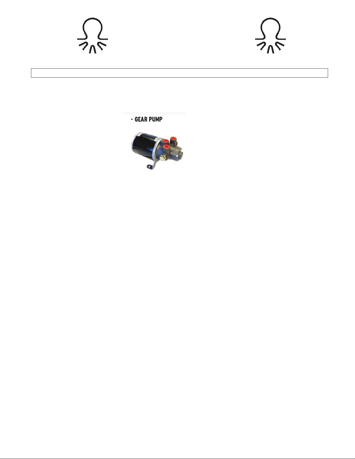
Octopus High Efficiency Gear Pumps are available in a range of sizes from 0.6 litres per minute to 1.6 litres per minute.
They are also available in 12vdc and 24vdc.
B. PUMP MODELS COVERED:
1. Octopus Hydraulic Gear Pump:
0.6 Litre per minute – 12v – OCTAFG0612.
1.0 Litre per minute – 12v – OCTAFG1012.
1.6 Litre per minute – 12v – OCTAFG1612.
0.6 Litre per minute – 24v – OCTAFG0624.
1.0 Litre per minute – 24v – OCTAFG1024.
1.6 Litre per minute – 24v – OCTAFG1624.
C. PUMP SELECTION - SIZING:
1. When sizing a pump for an autopilot application.
! The pump works with both balanced and unbalanced cylinders.
! Match the pump voltage to the power supply voltage from the
autopilot course computer.
! Size the pump considering the autopilot manufacturer’s recommended
rudder HO-HO speed for the type of vessel and the steering cylinder
volume.
! Rudder HO-HO speed usually falls within 10-15 seconds.
D. PUMP PREPARATION AND MOUNTING:
D1. PREPARATION:
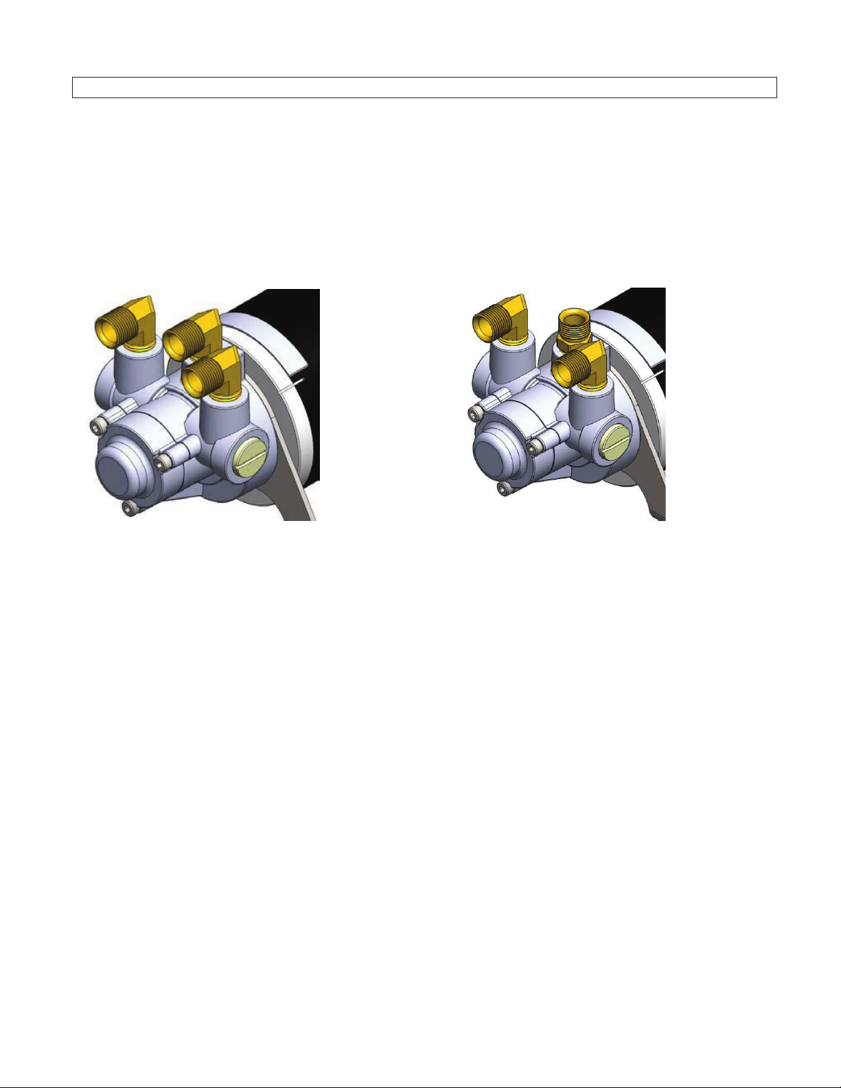
The Octopus Gear Pump housing has 3 x ¼ NPT female ports.
For a list of all available hose and fitting options see Table 1.
Octopus Reversing Pump Port Layouts & Fitting Options
OC14268
Page 3
OCTOPUS
INSTALLATION GUIDE – OCTOPUS GEAR PUMPS
Page 2 of 5 Subject to change without notice
Gear Pump Porting.
• 3 x ¼ NPT Female Ports – on front face.
• Flexibility to run lines into pump from front, rear or top must be gained by using fittings of best style to suite the
desired run. In any combination (example 2 x 90 degree elbows & 1 x straight), •
LH Sample shown has 3 x90 degree elbows (without captured sleeve & Nut).
• RH Sample shown has 2 x 90 degree elbows + 1 x straight (without captured sleeve and nut).
• Another option using “T” fittings would be to run lines from the helm pump to one leg of the “T” and a second
line from the second leg of the “T” the steering cylinder.
Table 1:
Additional hose and fitting options:
OC17SUK42- 30”, 750MM Hose and fitting kit, including NPT and ORB style Helm “T”
fitting kits
OC17SUK47- 4 Piece Orb style Helm “T” fitting kit to fit Seastar helms 2014 or newer
OC17SUK46- 4 Piece NPT style Helm “T” fitting kit to fit most helms 2014 or older
D2. MOUNTING:
The Octopus pump must be located at a level lower than the helm pump; it can be mounted in any orientation.
Care should be taken to ensure that the reservoir hose runs in an upwards path towards the Helm pump reservoir
connection with no loops or dips. This direct upwards path will ensure that no air pockets can get trapped. The
steering lines should also run as directly as possible.
E. HYDRAULIC CONNECTIONS:
1. In any hydraulic system it is important to use flexible hoses between the pump and the copper tubing to
protect the tubing against fatigue and also to isolate the more rigid tubing/structure from any noise that
the pump may generate.
2. The 2 steering ports must be connected to the tubes connecting the hand steering helm pump to the
steering cylinder.
Page 4

OCTOPUS
INSTALLATION GUIDE – OCTOPUS GEAR PUMPS
Page 3 of 5 Subject to change without notice
3. The reservoir port must be connected to the existing reservoir on the steering system. This is either a
separate pressurized reservoir or the steering helm itself. There is usually a port on the bottom of the
helm pump. If there are 2 helm stations; use the most convenient.
CAUTION:
1. Ensure that the existing hydraulic system has non-return (lock out) valves (check with the steering system
manufacturer); if it does not, then suitable valves must be fitted. Most modern steering systems do include
non-return valves.
2. A suitable liquid pipe thread sealer may be used sparingly. Do not use plastic or PTFE tape, this can very
easily separate and allow fragments into the system.
F. ELECTRICAL CONNECTIONS:
Follow the autopilot manufacturer’s instructions when connecting up the Octopus pump. Correct sizing of cable
is important. You have purchased the most efficient autopilot pump available today and it is not to your
advantage to compromise its performance by using undersize cable. Ensure all electrical connections are
properly made.
G. TYPICAL HYDRAULIC RETRO-FIT INSTALLATION PROCEDURE:
(Diagrams on next page)
The following example is based upon;
· A vessel with a 2 line hydraulic steering system.
· An existing manual steering helm with 1/4NPT ports.
· Utilizing an Octopus Hydraulic Hose and Fitting Kit – OC17SUK42
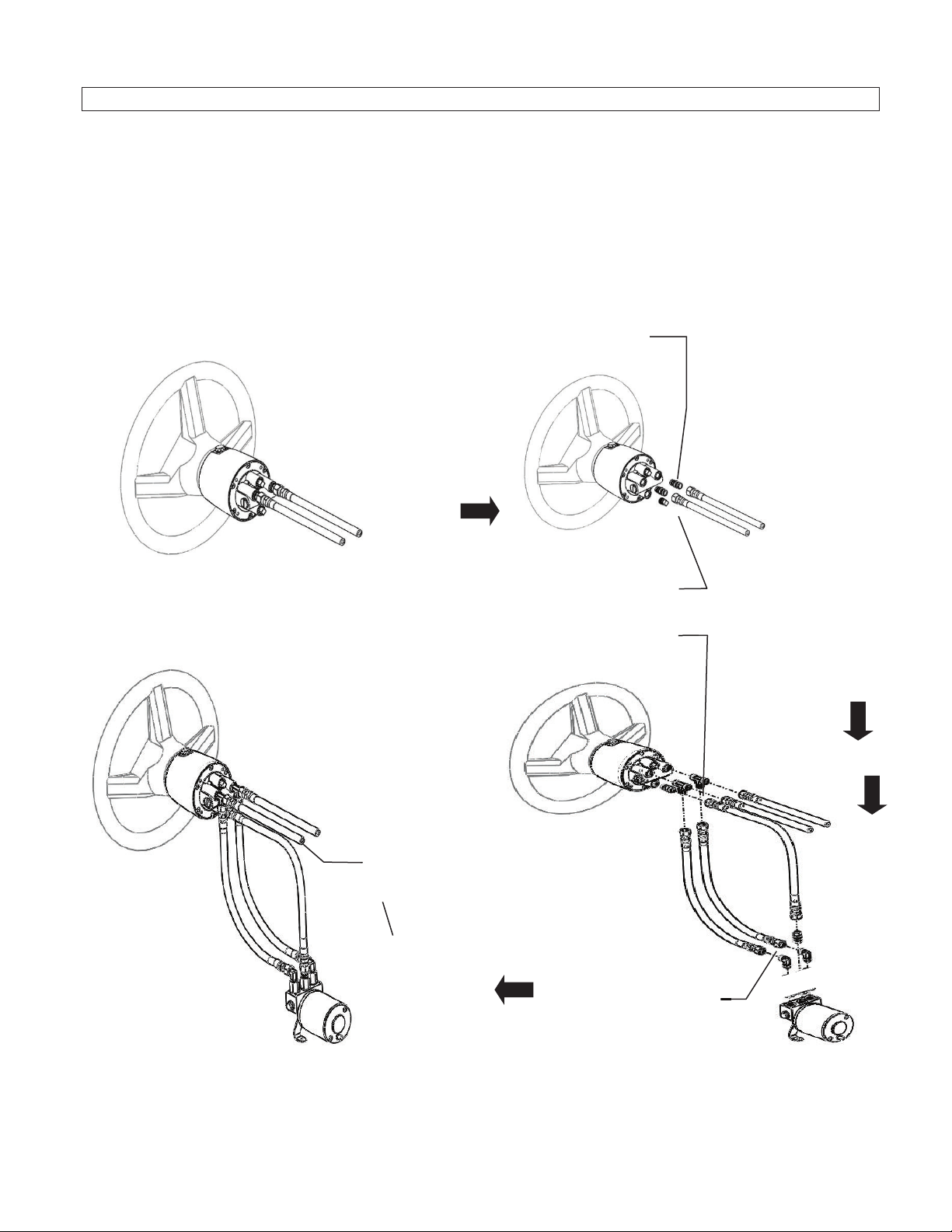
i. Working on the back side of the helm pump, identify and tag one of the existing steering hoses and its port
to assist in re-assembly.
ii. Disconnect 2 existing steering hoses.
iii. Remove and discard 2 fittings from the steering ports.
iv. Remove and discard the reservoir blanking plug from the lower port.
v. Install 2 tee fittings into steering ports
vi. Install either a straight or 90º angle fitting into the lower helm reservoir port - (choice depends on the routing
of the hose assembly – straight shown in diagrams).
vii. Re-connect 2 existing steering hoses to the most suitable connection of the tee fittings. (ensure that
steering hoses are connected to the correct side using tags applied in step i.).
viii. Choice of connection depends on the routing of the existing steering hoses – in-line shown in diagrams.
ix. Connect 2 high pressure steering hoses supplied with kit to the remaining connection of tee fittings.
x. Connect 1 x low pressure transparent hose supplied with kit to reservoir port fitting.
Page 5
OCTOPUS
INSTALLATION GUIDE – OCTOPUS GEAR PUMPS
Page 4 of 5 Subject to change without notice
xi. Install supplied fittings into Octopus pump as required to suit hose routing.
xii. Connect the 2 high pressure steering hoses and 1 low pressure transparent hose to Octopus pump.
xiii. Secure Octopus pump to vessel structure.
xiv. There will be fittings that are not used – they can be discarded.
xv. To increase the length of the standard hoses; additional hoses can be spliced.
xvi. Custom length hoses are available from the factory.
Remove & discard 3
Existing Steering
System
Install 2 Tee fittings & 1
straight/elbow fitting
Install fitting
combination
Lower Reservoir Port Plug
Connect all
Hoses & secure
To
Steering
Page 6

OCTOPUS
INSTALLATION GUIDE – OCTOPUS GEAR PUMPS
Page 5 of 5 Subject to change without notice
H. BLEEDING THE SYSTEM:
Bleeding the hydraulic system after installing the Octopus pump is a most important step; if there is any air left in
the system; the steering will feel unresponsive, especially at hard over. This can also affect the performance of
the Octopus pump, causing noise and degrading response times.
The electrical components (course computer and control head) must be installed and the Octopus pump
connected in order to utilize the pump during the bleeding procedure
The system reservoir must be full of hydraulic fluid before starting this procedure and this level must be
maintained during the procedure. See the steering system manufacturer’s guide for the exact procedure for your
steering system. (Note: this can vary depending upon the type of steering cylinder that is fitted).
Stage 1 – Purge the Octopus Pump to Helm Pump lines:
Using the autopilot control head:
Run the Octopus pump in one direction for 10-15 seconds.
Run the Octopus pump in the opposite direction for 10-15 seconds.
Repeat 2-3 times
Stage 2 – Purge the Helm Pump through to the steering cylinder.
The type of steering cylinder will dictate the specific procedure for this operation. See the steering system
manufacturer’s purging guide.
Stage 3 – Oil Level and System Check:
At this time the steering system must be checked for proper connections of all hoses and fittings and for air
removal. To do so: turn the steering wheel and pressurize very hard to port. Apply enough force to the wheel to
exceed the pressure relief valve setting. You will not harm the system. While pressure is maintained on the
steering wheel; check all port fittings and line connections for leaks. If no leaks are obvious your steering system
is ready for use. If leaks are found they must be corrected. Repeat this procedure for the starboard lines. Watch
the oil level in the helm pump when the steering reached both hard over positions. If there is no obvious drop in
the oil level; the air has been removed. If there is an obvious drop in oil level; you are compressing air and
further purging is required. Repeat the Stage 2 Purge.
I. SERVICE:
The Octopus Gear Pump requires no routine service. Installed correctly it will give many thousands of hours of
trouble free operation.
J. TROUBLESHOOTING:
If the unit fails to operate after installation is complete, check for the following common causes.
1. Motor does not run:
· No voltage applied to motor.
o Check voltage at motor with voltmeter.
· Autopilot not switched on correct setting.
o Check autopilot manual.
2. Motor runs but pump does not move the rudder:
· System not filled with oil.
o Fill and purge system.
· Hydraulic connection incorrect.
o Check that 2 steering ports connect to cylinder steering tubes.
· Reservoir line not connected.
o Must connect to reservoir.
 Loading...