

Page 1

NAVTEX RECEIVER
NX-700A/B
Page 2

Thepaperusedinthismanual
9-52 Ashihara-cho,9-52 Ashihara-cho,
A
A
*
0
*
0
*
0
*
0
*
O
*
O
*
O
*
O
Nishinomiya 662-8580, JAPANNishinomiya 662-8580, JAPAN
Telephone :Telephone : 0798-65-21110798-65-2111
FaxFax 0798-65-42000798-65-4200
::
iselementalchlorinefree.
Your Local Agent/Dealer Your Local Agent/Dealer
ll rights reserved.
ll rights reserved.
Pub. No.Pub. No. OME-56490OME-56490
(( HIMAHIMA ))
NX-700NX-700
Printed in JapanPrinted in Japan
FIRST EDITION :FIRST EDITION :MAY.MAY. 20052005
B1B1 :: JUL.JUL. 08, 200508, 2005
0015280401*
0015280401*
0015280401*
0015280401*
* 0 0 0 1 5 2 8 0 4 0 1 ** 0 0 0 1 5 2 8 0 4 0 1 *
ME56490B10*
ME56490B10*
ME56490B10*
ME56490B10*
* O M E 5 6 4 9 0 B 1 0 ** O M E 5 6 4 9 0 B 1 0 *
Page 3

IMPORTANT NOTICE
• No part of this manual may be copied or reproduced without written permission.
• If this manual is lost or worn, contact your dealer about replacement.
• The contents of this manual and equipment specifications are subject to change without
notice.
• The example screens (or illustrations) shown in this manual may not match the screens
you see on your display. The screen you see depends on your system configuration and
equipment settings.
• This manual is intended for use by native speakers of English.
• FURUNO will assume no responsibility for the damage caused by improper use or
modification of the equipment or claims of loss of profit by a third party.
• Please carefully read and follow the operation and maintenance procedures set forth in
this manual.
• Store this manual in a convenient place for further reference.
i
Page 4
SAFETY INSTRUCTIONS
Safety information for the Operator
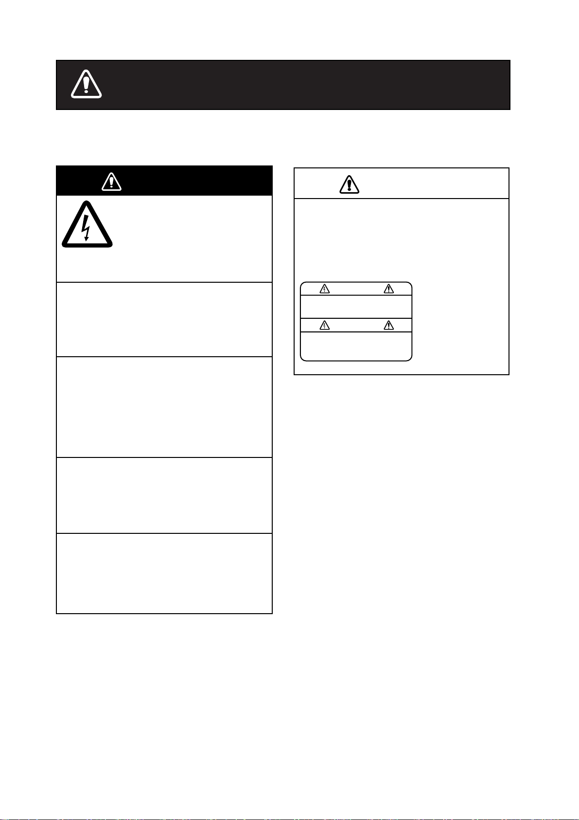
WARNING
ELECTRICAL SHOCK HAZARD
Do not open the equipment.
Only qualified personnel
should work inside the
equipment.
Do not disassemble or modify the
equipment.
Fire, electrical shock or serious injury can
result.
Immediately turn off the power at the
switchboard if the equipment is emitting
smoke or fire.
Continued use of the equipment can cause
fire or electrical shock. Contact a FURUNO
agent for service.
CAUTION
A warning label is attached to the equipment. Do not remove the label. If the
label is missing or damaged, contact
a FURUNO agent or dealer about
replacement.
WARNING
To avoid electrical shock, do not
remove cover. No user-serviceable
parts inside.
Name: Warning Label (1)
Type: 86-003-1011-1
Code No.: 100-236-231
Keep heater away from equipment.
A heater can melt the equipment's power
cord, which can cause fire or electrical
shock.
Use the proper fuse.
Fuse rating is shown on the equipment.
Use of a wrong fuse can result in damage
to the equipment.
ii
Page 5
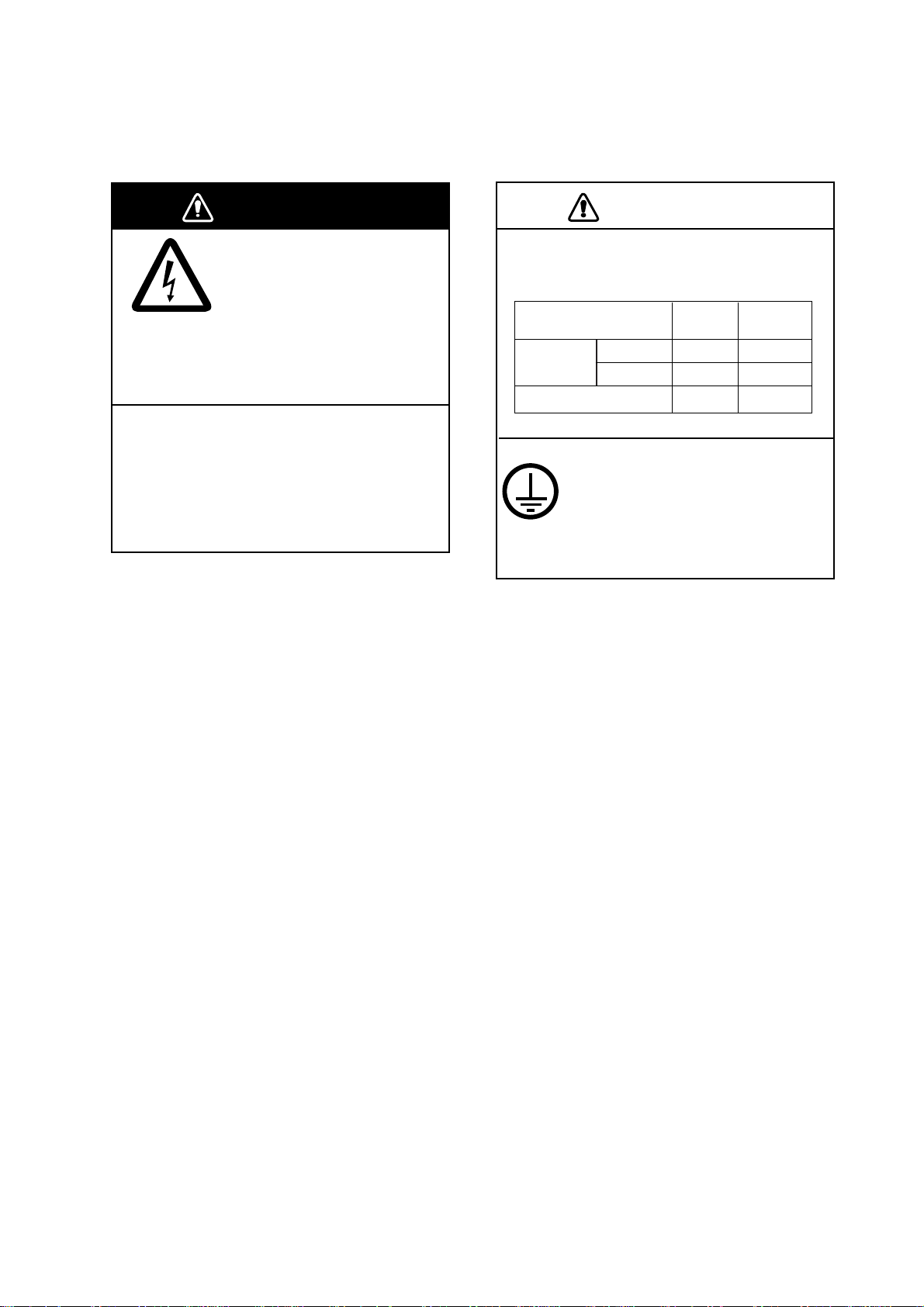
Safety information for the Installer
WARNINGWARNING
Do not open the equipment
unless totally familiar with
electrical circuits and
service manual.
ELECTRICAL
SHOCK
HAZARD
Turn off the power at the mains switchboard before beginning the installation.
Fire, electrical shock or serious injury can
result if the power is left on or is applied
while the equipment is being installed.
Only qualified personnel
should work inside the
equipment.
CAUTIONCAUTION
Observe the following compass safe
distances to prevent deviation of a
magnetic compass.
Steering
0.95 m
0.75 m
Display unit
Receiver unit NX-7001
NX-700A
NX-700B
Attach securely protective
earth to the ship's body.
The protective earth is required
to the power supply to prevent
electrical shock.
Standard
1.45 m
0.30 m 0.30 m
1.15 m
iii
Page 6

v
FORWORD
Congratul ations on your choice of the FURU NO NX-700A/B NAVTEX Receiver.
We are conf ident that y ou will enjoy many years of operation w ith this fine piec e
of equipment.
For over 50 y ears , Furuno Electr ic Company has enjoyed an enviable reputation
for quali ty and reliabil ity throughout the world. Our extens ive global network of
agents an d dealers furthers t his dedicati on to excell enc e.
The NX - 700A /B is just one of the many Furuno developments in t he field of
marine radi o com m unication.
NX-700A: Display unit w/printer
NX-700B: Display unit w/o printer
This NX-700A/B provides cost - effective price, high sens itivity and s imple
operati on in one compact and light-weight unit. In addition to its fundam ental
function of receiving NAVTEX broadcasts, this unit can also function as nav data
display when connected to navigation equipment.
This uni t is designed and const r uc ted to ensure the user many y ear s of
trouble-f ree operation. To obtain full performance from the equipment, however,
you should c ar efully read and follow the recom m ended procedures for
inst allation, operat ion and maintenanc e. No m achine can perform its intended
functions unless it is installed and maintained properly.
Thank you for considering and purchasing F URUNO equipment .
i
Page 7

v
Features
NAVTEX (Navigational Telex) is a world wide coastal telex broadcasting system.
Coastal NAVTEX broadcasting stations with specific ID’s transmit Navigational
warnings. Meteorological warnings, Search and Rescue (SAR) information and
other navigational information for NAVTEX receiver-equipped vessels sailing in
coastal waters.
The FURUNO NX-700 NAVTEX receiver receives NAVTEX messages and
automatically displays them together with station ID and message category
information.
If ship’s position data is fed from navigation equipment, the NX-700
automatically decides in which NAVAREA the vessel is navigating, and selects
stations. (NAVAREAs are geographical zones defined by the international
Maritime Organization.)
-Meets the following standards and regulations
MSC.148 (77) IMO A.694 (17)
IEC 61097-6 Ed.2 CDV (2005-02)
IEC 60945 Ed. 3 and 4
IEC 61162-1 and 2
EN 300 065V 1.1.3
EN 301 011V 1.1.1 (1998-09)
ITU-R M 540-2
ITU-R M 625-3
-Receives 518 kHz and another (490 or 4209.5 kHz) at the same time
-5” LCD display
-Prints out the message selected
-Bright 76 x 100 mm, monochrome LCD, 240 x 320 dots with adjustable contrast
and brilliance
-Low power consumption
-Displays the NAV data (date, own ship’s position, speed and course) or distance
(distance between own ship’s position and information mentioned in the
message) at the bottom of screen
Page 8

TABLE OF CONTENTS
EQUIPMENT LISTS...........................................................................................viii
SYSTEM CONFIGURATIONS .............................................................................. x
1. PRINCIPLE OF NAVTEX SYSTEM...............................................................1-1
1.1 How NAVTEX Works................................................................................................. 1-1
1.2 NAVTEX System Operation....................................................................................... 1-1
1.3 Message Format....................................................................................................... 1-2
1.4 NAVTEX Station Map................................................................................................ 1-3
1.5 NAVTEX Station List.................................................................................................. 1-4
2. OPERATION...................................................................................................2-1
2.1 Operating Controls.................................................................................................... 2-1
2.2 Turn the Unit On/Off .................................................................................................. 2-1
2.3 Adjusting LCD Dimmer.............................................................................................. 2-2
2.4 Confirming the New Message.................................................................................... 2-3
2.5 Sample Messages..................................................................................................... 2-4
2.6 Choosing the Receive Mode..................................................................................... 2-5
2.7 Choosing the Local Frequency.................................................................................. 2-6
2.8 Editing the Setting for Station and Message.............................................................. 2-6
2.9 Switchings the Frequency to Display......................................................................... 2-8
2.10 Alarm Messages........................................................................................................ 2-8
2.11 Processing Messages ............................................................................................... 2-9
2.12 Printing Messages................................................................................................... 2-10
2.13 Editing the NAVTEX S tation List.............................................................................. 2-12
2.14 Icons ....................................................................................................................... 2-15
2.15 Messages List......................................................................................................... 2-16
2.16 Other Functions....................................................................................................... 2-17
3. MAINTENANCE & TROUBLESHOOTING ...................................................3-1
3.1 Maintenance.............................................................................................................. 3-1
3.2 Replacement of Fuse, Battery, LCD and Therm al Pap er...........................................3-2
3.3 Troubleshooting......................................................................................................... 3-4
3.4 Diagnostics................................................................................................................ 3-5
3.5 Restoring All Defa ul t Set tings.................................................................................... 3-6
4. INSTALLATION..............................................................................................4-1
4.1 Display Unit............................................................................................................... 4-1
4.2 Receiver Unit.............................................................................................................4-3
4.3 Antenna Unit............................................................................................................. 4-4
4.4 Printer (NX-700B only).............................................................................................. 4-5
4.5 Wiring........................................................................................................................ 4-5
4.6 Setting of Printer...................................................................................................... 4-10
4.7 Digital Interfacing......................................................................................................4-11
vi
Page 9

MENU TREE....................................................................................................AP-1
SPECIFICATIONS........................................................................................... SP-1
PACKING LISTS ............................................................................................... A-1
OUTLINE DRAWINGS ...................................................................................... D-1
INTERCONNECTION DIAGRAM.......................................................................S-1
vii
Page 10

EQUIPMENT LISTS
Standard Supply
Name Type Code No. Qty Remarks
Display Unit
Receiver Unit NX-7001 - 1
Antenna Unit NX-7H - 1
Installation
Materials
Spare Parts SP08-02101* 004-514-370 1 Fuse for Receiver Unit*
Accessories FP08-00800* 000-040-396 1 For NX-700A
NX-700A - w/printer
NX-700B - 1 w/o printer
CP08-01810 000-040-180 10 m cable, CP08-01811*
CP08-01820 000-040-210 20 m cable, CP08-01811*
CP08-01870 000-040-350 30 m cable, CP08-01811*
CP08-01880 000-040-362 40 m cable, CP08-01811*
CP08-01890 000-040-363
CP08-01860 000-040-349 1
CP08-01863* 004-514-530 1
CP08-01864* 004-514-540
CP08-01861* 004-514-350 1 For Display Unit
1
50 m cable, CP08-01811*
DSUB25P cable, between
Display and Receiver Units
For Antenna Unit w/o antenna
cable
For Antenna Unit w/ antenna
cable.
*: See the back of this manual.
viii
Page 11

Optional Supply
Name Type Code No. Qty Remarks
Thermal Paper TP058-30CL 000-154-047 1 set For NX-700A
Flush Mount Kit
AC-DC Power PR-240-CE 000-053-373 1
Extension Cable Kit
Coaxial Cable RG-10/U-Y
Cable Assy DSUB25P-DSUB25P
Right Angle Mounting
Base
L-Angle Mounting
Base
Handrail Mounting
Base
Mast Mounting Kit CP20-01111 004-365-780 1
Display Unit
OP08-19 004-514-810 1 For NX-700A
OP08-20 004-514-820 1 For NX-700B
000-041-174 1 10 m, w/connector
000-041-175 1 20 m, w/connector
OP04-2
OP08-12
No.13-QA330 000-803-239 1
No.13-QA310 000-803-240 1
No.13-RC5160 000-806-114 1
NX-700A -
NX-700B -
000-041-176 1 30 m, w/connector
000-041-177 1 40 m, w/connector
000-041-178 1 50 m, w/connector
005-948-250 1 10 m
005-948-260 1 20 m
005-948-270 1 30 m
005-948-280 1 40 m
005-948-290 1 50 m
000-563-048 1 30 m
000-126-000 1 40 m
000-126-001 1 50 m
000-152-698 1 3 m
000-152-699 1 5 m
000-152-700 1 10 m
000-152-701 1 15 m
For antenna unit NX-7H
1
ix
Page 12
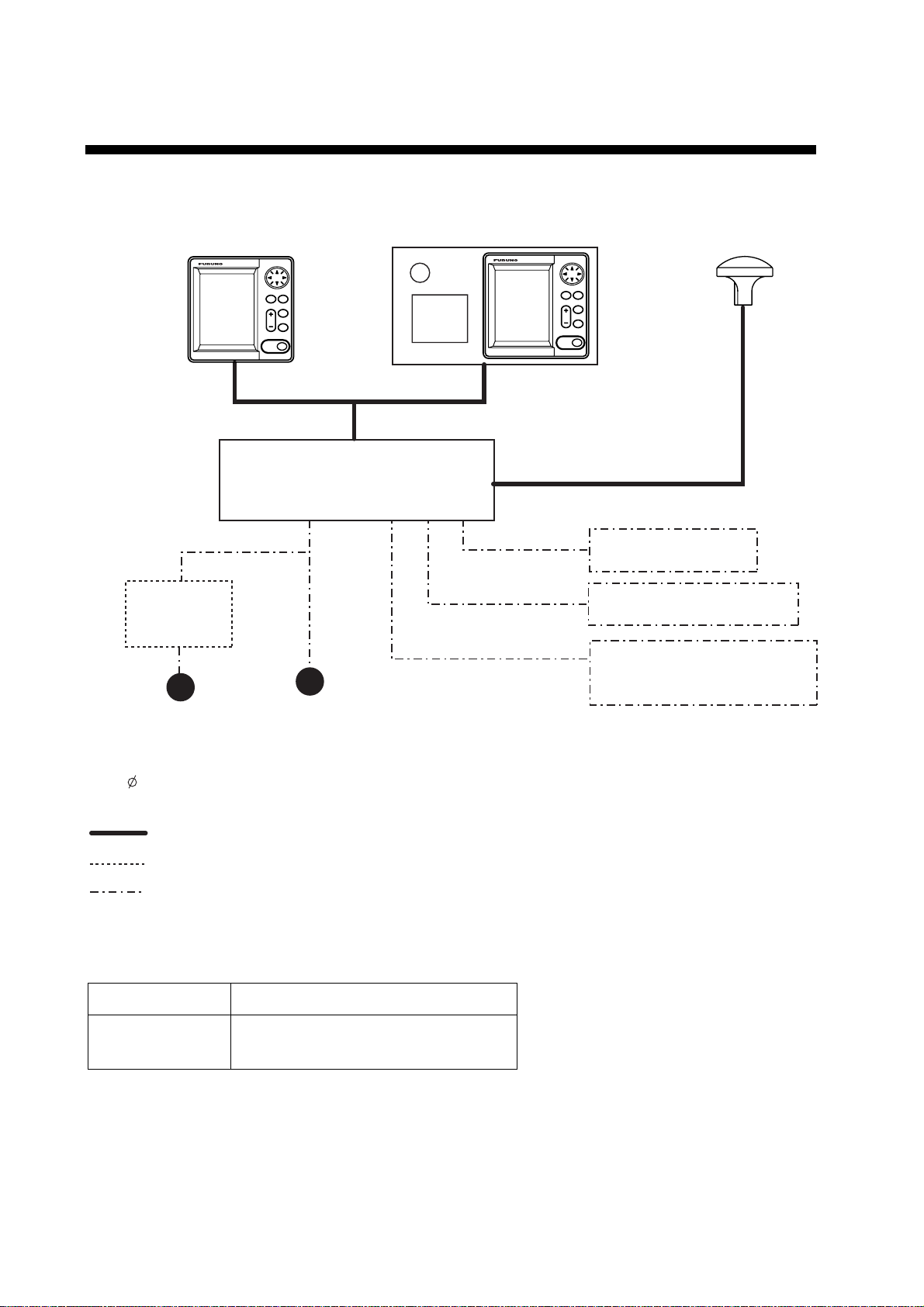
SYSTEM CONFIGURATIONS
DISPLAY UNIT
NX-700B
Rectifier
PR-240-CE
Power supply
100-115/
200-230 V A C.
1 , 50/60 Hz
or
Max. 15 m
RECEIVER UNIT
NX-7001
Power supply
12-24 VDC
DISPLAY UNIT
NX-700A
ANTENNA UNIT
NX-7H
Max. 100 m
External Alarm
Printer (NX-700B only)
INS
(Integrated Navigation System)
or
Navigator
: Standard
: Option
: User supply
Environmental Category
Antenna unit To be installed in an exposed area
Display unit
Receiver unit
To be installed in a protected area
x
Page 13
1. PRINCIPLE OF NAVTEX SYSTEM
1.1 How NAVTEX Works
NAVTEX is an acronym meaning Navigational Telex, and as its name shows, it is
a kind of narrow band radio teletype system for sending (by frequency shift
keying) text messages expressed in a 7-unit code. The difference is that a
NAVTEX transmitter transmits nine control characters (header code) ahead of
the main message, so that the receiver can identify the station, message type
and serial number automatically.
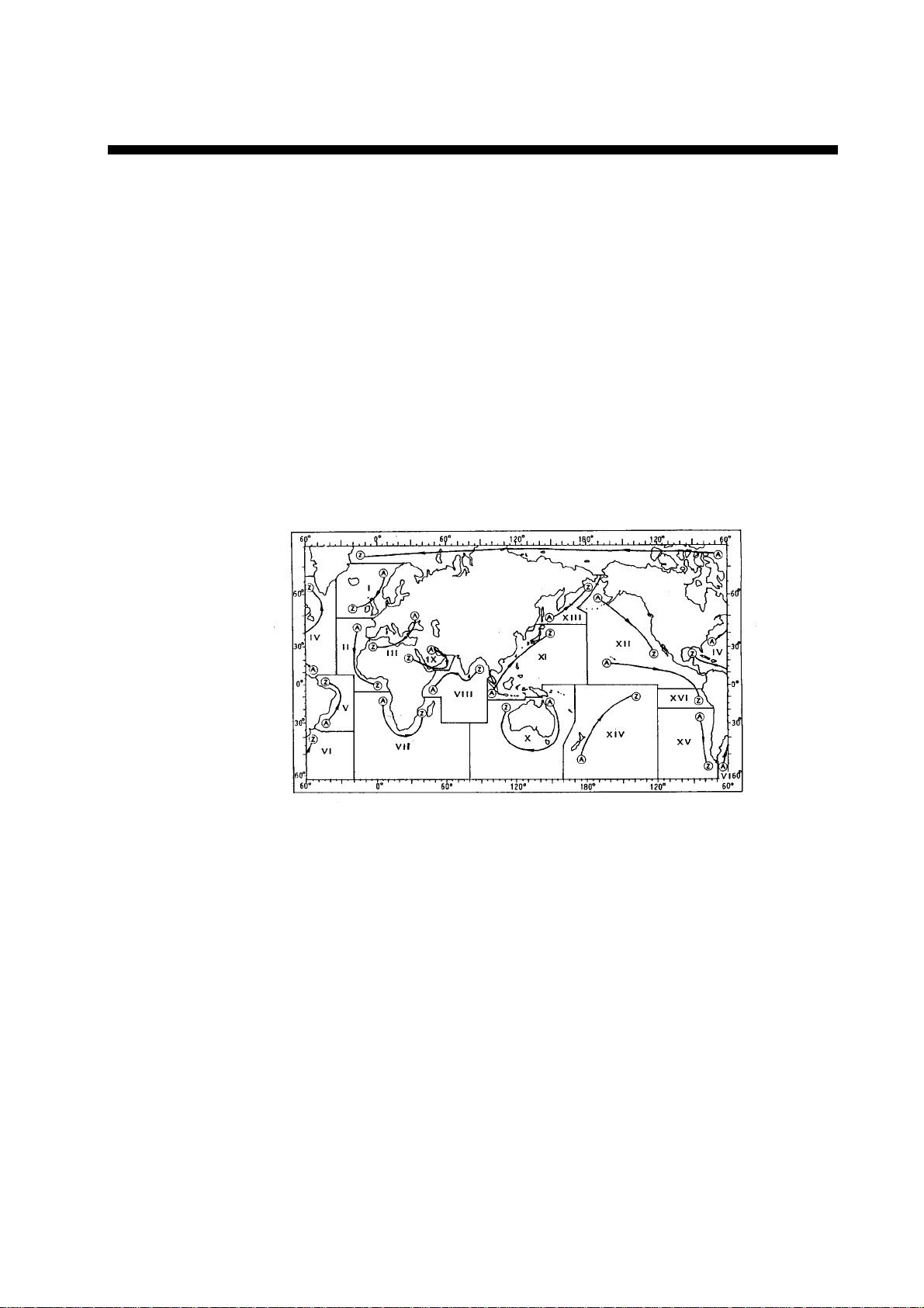
1.2 NAVTEX System Operation
For navigation purposes, the world is divided into 16 areas as shown in the
figure below. Each Navtex station has an identification code, from “A” to “Z”. The
frequency assigned to Navtex are 518 kHz and another (490 or 4209.5 kHz),
and many stations exist in the same service coverage.
If the stations were to transmit without any rule, the system would collapse due
to mutual interference. To avoid this problem, the following rules apply.
• The transmission schedule is determined so that two or more stations having
a common service area may not overlap in time.
• Each station transmits with minimum required power to cover its service area
(200 to 400 nautical miles nominal).
1-1
Page 14

1. PRINCIPLE OF NAVTEX SYSTEM
1.3 Message Format
For automatic identification of messages, each message starts with nine control
characters, called “Header codes”.
The first five characters are always “ZCZC_“ and common to all messages. This
part is used for message synchronization. The latter four characters are
designed as B1, B2, B3 and B4 indicate origin, category and serial number of
the message.
Character B1 is the identification letter of the Navtex station “A” thru “Z”.
Character B2 indicates the type of message. “A” thru “Z”, as listed below.
Character B3 and B4 indicate the serial number of the message. The serial
numbers are counted up from “01” to “99”, and starts from “01” again. Number
“00” is specially reserved for important emergency messages.
The end of each message is indicated by “NNNN” (four successive N’s).
General message format is summarized below.
Header code
ZCZC B1 B2 B3 B4 main message NNNN
Start code
Main message
Termination code
(sync)
Serial number
"00": Emergency message
"01" - "99": Normal message
Type of message
"A" - "Z"
(See the list below.)
Station ID
"A" - "Z"
[Type of message (category)]
A: Navigational warning I: Spare
B: Meteorological warning J: SATNAV message
C: Ice report K:
D:
Search and rescue information/pirate
attack warnings
L:
Other electronic navigational aid
system message
Navigational warning (addition to
“A”)
E: Meteorological forecast
F: Pilot message
G: AIS
H: LORAN message Z: QRU (no message on hand)
1-2
V to Y
Special services allocation by the
NAVTEX Co-ordinating Panel
Page 15
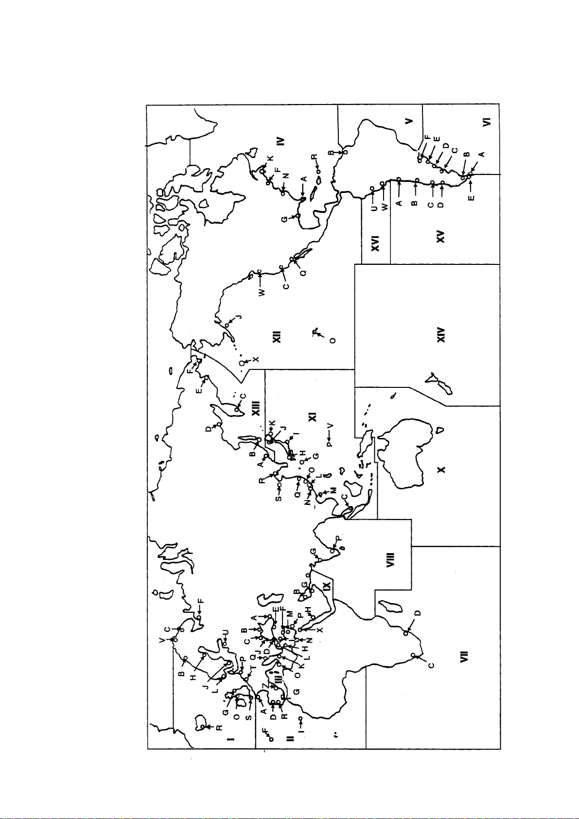
1.4 NAVTEX Station Map
1. PRINCIPLE OF NAVTEX SYSTEM
1-3
Page 16

1. PRINCIPLE OF NAVTEX SYSTEM
1.5 NAVTEX Station Li st
NAV
area
I Belgium Oostende 51 11 N 02 48 E 518 55 T 0310, 0710, 1110, 1510, 1910, 2310
Country
Estonia Tallinn 59 30 N 24 30 E 518 250 U 0320, 0720, 1120, 1520, 1920, 2320
Iceland Reykjavik Radio 64 05 N 21 51 W
Ireland Valentia 51 27 N 09 49 W 518 400 W 0340, 0740, 1140, 1540, 1940, 2340
Malin Head 55 22 N 07 21 W 518 400 Q 0240, 0640, 1040, 1440, 1840, 2240
France Niton 50 35 N 01 18 W 518 270 K 0140, 0540, 0940, 1340, 1740, 2140
Netherlands Den Helder 52 06 N 04 15 E 518 110 P 0230, 0630, 1030, 1430, 1830, 2230
Norway Bodo Radio 67 16 N 14 23 E 518 450 B 0010, 0410, 0810, 1210, 1610, 2010
Rogaland Radio 58 48 N 05 34 E 518 450 L 0150, 0550, 0950, 1350, 1750, 2150
Vardoe Radio 70 22 N 31 06 E 518 450 V 0330, 0730, 1130, 1530, 1930, 2330
Svalbard 78 04 N 13 38 E 518 450 A 0000, 0400, 0800, 1200, 1600, 2000
Orlandet 63 40 N 09 33 E 518 450 N 0210, 0610, 1010, 1410, 1810, 2210
Sweden Bjuroklubb 64 28 N 21 36 E 518 300 H 0110, 0510, 0910, 1310, 1710, 2110
Station
Latitude Longitude
Freq.
(kHz)
Area
Station
(nm)
518 550 R 0250, 0650, 1050, 1450, 1850, 2250
490 550 R 0318, 0718, 1118, 1518, 1918, 2318
ID
Broadcast schedule (UTC)
Gislovshammar 55 29 N 14 19 E 518 300 J 0130, 0530, 0930, 1330, 1730, 2130
Grimeton 57 06 N 12 23 E 518 300 D 0030, 0430, 0830, 1230, 1630, 2030
United
Kingdom
Portpatric k 54 51 N 05 07 W
Niton 50 35 N 01 18 W
Oostende 51 11 N 02 48 E 518 150 M 0200, 0600, 1000, 1400, 1800, 2200
II France Cross Corsen 48 28 N 05 03 W
Niton 50 35 N 01 18 W 490 270 T 0310, 0710, 1110, 1510, 1910, 2310
Portugal Horta 38 32 N 28 38 W 518 640 F 0050, 0450, 0850, 1250, 1650, 2050
Monsanto 38 44 N 09 11 W
Spain Coruna 43 21 N 08 27 W 518 400 D 0030, 0430, 0830, 1230, 1630, 2030
Cullercoats 55 02 N 01 26 W
518 270 G 0100, 0500, 0900, 1300, 1700, 2100
490 270 U 0320, 0720, 1120, 1520, 1920, 2320
518 270 O 0220, 0620, 1020, 1420, 1820, 2220
490 270 C 0020, 0420, 0820, 1220, 1620, 2020
518 270 E 0040, 0440, 0840, 1240, 1640, 2040
490 270 I 0120, 0520, 0920, 1320, 1720, 2120
518 300 A 0000, 0400, 0800, 1200, 1600, 2000
490 300 E 0040, 0440, 0840, 1240, 1640, 2040
518 530 R 0250, 0650, 1050, 1450, 1850, 2250
490 530 G 0100, 0500, 0900, 1300, 1700, 2100
Tarifa 36 01 N 05 34 W 518 400 G 0100, 0500, 0900, 1300, 1700, 2100
Las Palmas 28 10 N 15 25 W 518 400 I 0120, 0520, 0920, 1320, 1720, 2120
(Continued on next page)
1-4
Page 17

1. PRINCIPLE OF NAVTEX SYSTEM
NAV
area
III Bulgaria Varna 43 04 N 27 46 E 518 350 J 0130, 0530, 0930, 1330, 1730, 2130
Croatia Split radio 43 30 N 16 29 E 518 85 Q 0240, 0640, 1040, 1440, 1840, 2240
C yprus Cypradio 35 03 N 33 17 E 518 200 M 0200, 0600, 1000, 1400, 1800, 2200
Egypt Alexandria 31 12 N 29 52 E 518 350 N 0210, 0610, 1010, 1410, 1810, 2210
Serapeum 30 28 N 32 22 E 4209.5 400 X 0750, 1150
Country
Station
Latitude Longitude
Freq.
(kHz)
Area
(nm)
Station
ID
Broadcast schedule (UTC)
France Toulon 43 06 N 05 59 E
Greece Iraklion 35 20 N 25 07 E 518 280 H 0110, 0510, 0910, 1310, 1710, 2110
Kerkyra 39 37 N 19 55 E 518 280 K 0140, 0540, 0940, 1340, 1740, 2140
Limnos 39 52 N 25 04 E 518 280 L 0150, 0550, 0950, 1350, 1750, 2150
Israel Haifa 32 49 N 35 00 E 518 200 P 0020, 0420, 0820, 1220, 1620, 2020
Italy Roma 41 48 N 12 31 E 518 320 R 0250, 0650, 1050, 1450, 1850, 2250
Augusta 37 14 N 15 14 E 518 320 V 0330, 0730, 1130, 1530, 1930, 2330
Cagliari 39 14 N 09 14 E 518 320 T 0310, 0710, 1110, 1510, 1910, 2310
Trieste 45 41 N 13 46 E 518 320 U 0320, 0720, 1120, 1520, 1920, 2320
Malta Malta 35 49 N 14 32 E 518 400 O 0220, 0620, 1020, 1420, 1820, 2220
Russian
Federation
Spain Cabo de la Nao 38 43 N 00 09 E 518 300 X 0350, 0750, 1150, 1550, 1950, 2350
Turkey Istanbul 41 04 N 28 57 E 518 300 D 0030, 0430, 0830, 1230, 1630, 2030
Samsun 41 17 N 36 20 E 518 300 E 0040, 0440, 0840, 1240, 1640, 2040
Novorossiysk 44 42 N 37 44 E 518 300 A 0300, 0700, 1100, 1500, 1900, 2300
518 250 W 0340, 0740, 1340, 1540, 1940, 2340
490 250 S 0300, 0700, 1100, 1500, 1900, 2300
Antalya 36 53 N 30 42 E 518 300 F 0050, 0450, 0850, 1250, 1650, 2050
Izmir 38 22 N 26 36 E 518 300 I 0120, 0520, 0920, 1320, 1720, 2120
Ukraine Mariupol 47 06 N 37 33 E 518 280 B 0100, 0500, 0900, 1300, 1700, 2100
Odessa 46 29 N 30 44 E 518 280 C 0230, 0630, 1030, 1430, 1830, 2230
Bermuda
IV
(UK)
Canada
Wiarton 44 20 N 81 10 W 518 300 H 0110, 0510, 0910, 1310, 1710, 2110
St. Johns 47 30 N 52 40 W 518 300 O 0220, 0620, 1020, 1420, 1820, 2220
Thunder Bay 48 25 N 89 20 W 518 300 P 0230, 0630, 1030, 1430, 1830, 2230
Sydney, NS 46 10 N 60 00 W 518 300
Yarmouth 43 45 N 66 10 W 518 300
Bermuda 32 23 N 64 41 W 518 280 B 0010, 0410, 0810, 1210, 1610, 2010
Riviere-au-Renard
50 11 N 66 07 W 518 300
C D 0020, 0420, 0820, 1220, 1620, 2020
0035, 0435, 0835, 1235, 1635, 2035
Q J 0240, 0640, 1040, 1440, 1840, 2240
0255, 0655, 1055, 1455, 1855, 2255
U V 0320, 0720, 1120, 1520, 1920, 2320
0335, 0735, 1135, 1535, 1935, 2335
(Continued on next page)
1-5
Page 18

1. PRINCIPLE OF NAVTEX SYSTEM
NAV
area
IV Canada Labrador 53 42 N 57 01 W 518 300 X 0350, 0750, 1150, 1550, 1950, 2350
Country
Station
Latitude Longitude
Freq.
(kHz)
Area
(nm)
Station
ID
Broadcast schedule (UTC)
Iqaluit, NU 63 43 N 68 33 W
United States Miami 25 37 N 80 23 W 518 240 A 0000, 0400, 0800, 1200, 1600, 2000
Boston 41 43 N 70 30 W 518 200 F 0445, 0845, 1245, 1645, 2045, 0045
New Orleans 29 53 N 89 57 W 518 200 G 0300, 0700, 1100, 1500, 1900, 2300
Portsmouth 36 43 N 76 00 W 518 280 N 0130, 0530, 0930, 1330, 1730, 2130
Isabella 18 28 N 67 04 W 518 200 R 0200, 0600, 1000, 1400, 1800, 2200
Savannah, GA 32 08 N 81 42 W 518 200 E 0040, 0440, 0840, 1240, 1640, 2040
Netherlands
Antilles
V NIL
VI Argentina Ushaia 54 48 S 68 18 W 518 280 M 0200, 0600, 1000, 1400, 1800, 2200
Rio Gallegos 51 37 S 65 03 W 518 280 N 0210, 0610, 1010, 1410, 1810, 2210
Bahia Blanc a 38 43 S 62 06 W 518 280 P 0230, 0630, 1030, 1430, 1830, 2230
Curacao 12 10 N 68 52 W 518 400 H 0110, 0510, 0910, 1310, 1710, 2110
Comodoro
Rivadavia
45 51 S 67 25 W 518 280 O 0220, 0620, 1020, 1420, 1820, 2220
518 300 T 0310, 0710, 1110, 1510, 1910, 2310
490 300 S 0300, 0700, 1100, 1500, 1900, 2300
Mar del Plata 38 03 S 57 32 W 518 280 Q 0240, 0640, 1040, 1440, 1840, 2240
Buenos Aires 34 36 S 58 22 W 518 560 R 0250, 0650, 1050, 1450, 1850, 2250
Uruguay La Paloma 34 40 S 54 09 W
VII Namibia W alvis Bay 23 03 S 14 37 E 518 378 B 0010, 0410, 0810, 1210, 1610, 2010
South Africa Cape Town 33 40 S 18 43 E 518 500 C 0020, 0420, 0820, 1220, 1620, 2020
Port Elizabeth 34 02 S 25 33 E 518 500 I 0120, 0520, 0920, 1320, 1720, 2120
Durban 30 00 S 31 30 E 518 500 O 0220, 0620, 1020, 1420, 1820, 2220
VIII India Mumbay 19 05 N 72 50 E 518 250 G 0100, 0500, 0900, 1300, 1700, 2100
Madras 13 08 N 80 10 E 518 400 P 0230, 0630, 1030, 1430, 1830, 2230
Mauritius Mauritius R adio 20 10 S 57 28 E 518 400 C 0020, 0420, 0820, 1220, 1620, 2020
IX Bahrain Hamala 26 09 N 50 28 E 518 300 B 0010, 0410, 0810, 1210, 1610, 2010
Egypt Serapeum 30 28 N 32 22 E
Kosseir 26 06 N 34 17 E 518 400 V 0330, 0730, 1130, 1530, 1930, 2330
Iran Bushehr 28 59 N 50 50 E 518 300 A 0000, 0400, 0800, 1200, 1600, 2000
518 280 F 0050, 0450, 0850, 1250, 1650, 2050
490 280 A 0000, 0400, 0800, 1200, 1600, 2000
518 200 X 0350, 0750, 1150, 1550, 1950, 2350
4209.5 200 X 0750, 1150
Bandar Abbas 27 07 N 56 04 E 518 300 F 0050, 0450, 0850, 1250, 1650, 2050
(Continued on next page)
1-6
Page 19

1. PRINCIPLE OF NAVTEX SYSTEM
NAV
area
IX Saudi Arabia Jeddah 21 23 N 39 10 E 518 390 H 0705, 1305, 1905
Oman Muscat 23 36 N 58 30 E 518 270 M 0200, 0600, 1000, 1400, 1800, 2200
Pakistan Karachi 24 51 N 67 03 E 518 400 P 0230, 0630, 1030, 1430, 1830, 2230
X NIL
XI China Sanya 18 14 N 109 30 E 518 250 M 0200, 0600, 1000, 1400, 2200
Guangzhou 23 08 N 113 32 E 518 250 N 0210, 0610, 1010, 1410, 2210
Fuzhou 26 01 N 119 18 E 518 250 O 0220, 0620, 1020, 1420, 2220
Shanghai 31 08 N 121 33 E 518 250 Q 0240, 0640, 1040, 1440, 2240
Dalian 38 52 N 121 31 E 518 250 R 0250, 0650, 1050, 1450, 2250
Indonesia Jayapura 02 31 S 140 43 E 518 300 A 0000, 0400, 0800, 1200, 1600, 2000
Ambon 03 42 S 128 12 E 518 300 B 0010, 0410, 0810, 1210, 1610, 2010
Makassar 05 06 S 119 26 E 518 300 D 0030, 0430, 0830, 1230, 1830, 2030
Jakarta 06 06 S 106 54 E 518 300 E 0040, 0440, 0840, 1240, 1640, 2040
Japan Otaru 43 19 N 140 27 E 518 400 J 0130, 0530, 0930, 1330, 1730, 2130
Country
Station
Latitude Longitude
Freq.
(kHz)
Area
(nm)
Station
ID
Broadcast schedule (UTC)
Kushiro 42 57 N 144 36 E 518 400 K 0140, 0540, 0940, 1340, 1740, 2140
Yokohama 35 14 N 139 55 E 518 400 I 0120, 0520, 0920, 1320, 1720, 2120
Moji 34 01 N 130 56 E 518 400 H 0110, 0510, 0910, 1310, 1710, 2110
Naha 26 05 N 127 40 E 518 400 G 0100, 0500, 0900, 1300, 1700, 2100
Korea,
Republic of
Pyongsan 35 36 N 126 29 E
Malaysia Penang 05 26 N 100 24 E 518 350 U 0320, 0720, 1120, 1520, 1920, 2320
Miri 04 28 N 114 01 E 518 350 T 0310, 0710, 1110, 1510, 1910, 2310
Sandakan 05 54 N 118 00 E 518 350 S 0300, 0700, 1100, 1500, 1900, 2300
Singapore Singapore 01 25 N 103 52 E 518 400 C
Thailand Bangkok Radio 13 43 N 100 34 E 518 200 F 0050, 0450, 0850, 1250
United States Guam 13 29 N 144 50 E 518 100 V 0100, 0500, 0900, 1300, 1700, 2100
Chukpyong 37 03 N 129 26 E
518 200 V 0330, 0730, 1130, 1530, 1930, 2330
490 200 J 0130, 0530, 0930, 1330, 1730, 2130
518 200 W 0340, 0740, 1340, 1540, 1940, 2340
490 200 K 0140, 0540, 0940, 1340, 1740, 2140
0020-0030, 0420-0430, 0820-0830,
1220-1230, 1620-1630, 2020-2030
(Continued on next page)
1-7
Page 20

1. PRINCIPLE OF NAVTEX SYSTEM
NAV
area
XI Vietnam Ho Chi Minh City 10 47 N 106 40 E 518 400 X 0350, 0750, 1150, 1550, 1950, 2350
Country
Station
Latitude Longitude
Freq.
(kHz)
Area
(nm)
Station
ID
Broadcast schedule (UTC)
Haiphong 20 44 N 106 44 E
D anang 16 05 N 108 13 E 518 400 K 0140, 0540, 0940, 1340, 1740, 2140
Taiwan Kaohsiung 22 29 N 120 25 E 518 216 P 0230, 0630, 1030, 1430, 1830, 2230
Associate
Member of IMO
XII Canada Prince Rupert 54 20 N 130 20 W 518 300 D 0030, 0430, 0830, 1230, 1630, 2030
Tofino 48 55 N 125 35 W 518 300 H 0110, 0510, 0910, 1310, 1710, 2110
United States San Francisco 37 55 N 122 44 W 518 350 C 0400, 0800, 1200, 1600, 2000, 2400
Kodiak 57 46 N 152 34 W 518 200 J 0300, 0700, 1100, 1500, 1900, 2300
H onolulu 21 22 N 158 09 W 518 350 O 0040, 0440, 0840, 1240, 1640, 2040
C ambria 35 31 N 121 03 W 518 350 Q 0445, 0845, 1245, 1645, 2045, 0045
Astoria 46 10 N 123 49 W 518 216 W 0130, 0530, 0930, 1330, 1730, 2130
Russian
XIII
Federation
Mur mansk 68 46 N 32 58 E 518 300 C 0020, 0420, 0820, 1220, 1620, 2020
Hong Kong 22 13 N 114 15 E 518 400 L 0150, 0550, 0950, 1350, 1750, 2150
Kholmsk 47 02 N 142 03 E 518 300 B 0010, 0410, 0810, 1210, 1610, 2010
490 400 W 0340, 1540
4209.5 400 W 0230, 0630, 1030, 1430, 1830, 2230
Arkhangelsk 64 51 N 40 17 E 518 300 F 0050, 0450, 0850, 1250, 1650, 2050
Astrakhan 45 47 N 47 33 E 518 250 W 0340, 0740, 1140, 1540, 1940, 2340
XIV NIL
XV Chile Antofagasta 23 40 S 70 25 W 518 300
Valparaiso 32 48 S 71 29 W 518 300
Talcahuano 36 42 S 73 06 W 518 300
Puerto Montt 41 30 S 72 58 W 518 300
Punta Arenas 53 09 S 70 58 W 518 300
Isla de Pascua 27 09 S 109 25 W 518 300
XVI Peru Paita 05 05 S 81 07 W 518 200 S 0300, 0700, 1100, 1500, 1900, 2300
Callao 12 03 S 77 09 W 518 200 U 0320, 0720, 1120, 1520, 1920, 2320
A H 0400, 1200, 2000
0000, 0800, 1600
B I 0410, 1210, 2010
0010, 0810, 1610
C J 0420, 1220, 2020
0020, 0820, 1620
D K 0430, 1230, 2030
0030, 0830, 1630
E L 0440, 1240, 2040
0040, 0840, 1640
F G 0450, 1250, 2050
0050, 0850, 1650
Mollendo 17 01 S 72 01 W 518 200 W 0340, 0740, 1140, 1540, 1940, 2340
Note: The list shows the stations listed at Longwave Navtex Broadcasts (Oct. 2004).
1-8
Page 21
2. OPERATION
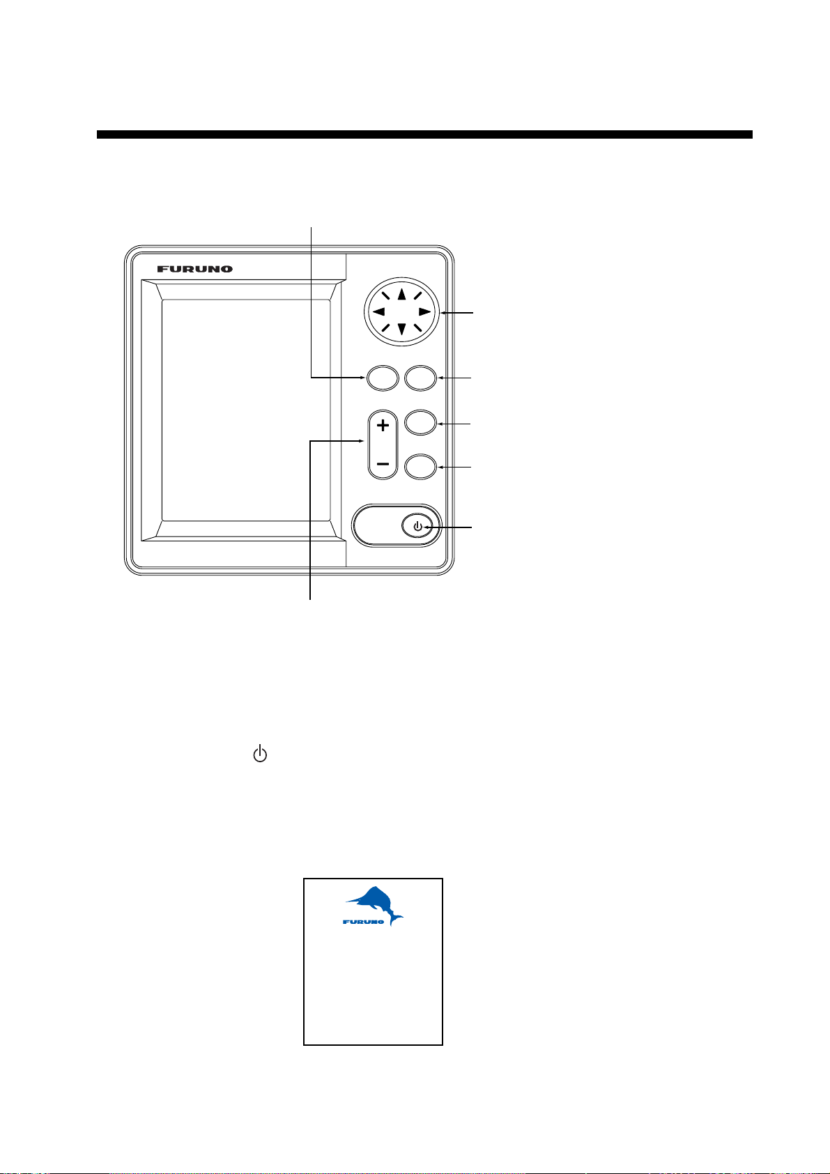
2.1 Operating Controls
Registers items on menus.
MENU
ENT
ESC
Cursor pad
-Shifts the cursor and display.
-Selects items on menus.
Opens menu/Returns to the previous display.
LIST
DIM
PRINT
Adjusts the panel and LCD dimmer.
+: Raises the setting.
- : Decreases the setting.
Display unit, front vi ew
2.2 Turning the Unit On/Off
Press the
the start up display, where the ROM and RAM are checked for proper operation
and the program no. is displayed. The results of the check are shown as OK or
NG (No Good).
When the results are OK, the list display is shown after five seconds after
completion of the check, with frequency last used before turning the power off.
key to turn the unit on. A beep sounds and the equipment shows
Opens the LIST options.
Opens the PRINT options.
Turns the power on/off.
DUAL CHANNEL NAVTEX
NX-700
FURUNO ELECTRIC CO., LTD.
ROM : OK RAM : OK
Program No. 0850193-XX
XX: Program version No.
2-1
Page 22
2. OPERATION
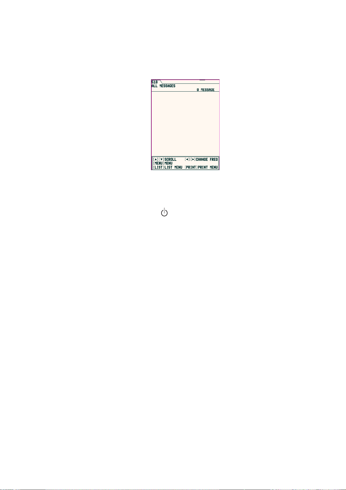
At the default setting, the equipment functions as below;
When the results of the check are OK, ALL MESSAGE display for 518 kHz
appears. This screen shows all messages received in 518 kHz.
You can switch 518 kHz (International message) and 490 kHz (local message) to
display. The NX-700A is preset to print all received message out.
Note 1: To display all received messages in 490 kHz, press ◄ or ►.
Note 2: To cancel the printing all received messages out, see page 2-11.
To turn the power off, press the
Note: If NG appears for any test, try to press any key to go to the next stage.
All message display (518 kHz)
key again.
The equipment, however, may not be operated properly. Contact your
dealer if the problem persists.
2.3 Adjusting LCD Dimmer
You can adjust LCD and panel dimmer with the + DIM – key. The adjustment
range is 0 (dark) to 9 (bright).
+: Raises the dimmer.
-: Decreases the dimmer.
2-2
Page 23
2.4 Confirming the New Message
When you receive a new message, do one of the following depending on
message received.
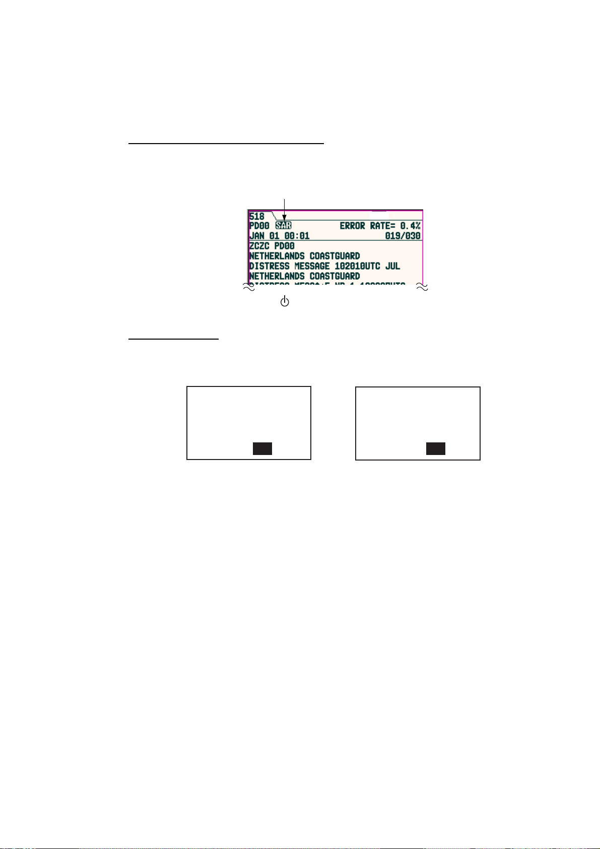
SAR (Search and Rescue) mes sage
1. When an SAR message is received, the audible alert sounds and details for
the SAR message appear.
Icon for SAR message
2. Press any key other than
Other messages
key to silence the alarm.
2. OPERATION
1. When a message other than an SAR message is received, the display shows
one of the following windows.
Received new int'l msg.
Display new msg ?
Yes No
International message
2. If you want to read the message immediately, press ◄ to choose “Yes” and
then press the ENT key to display the message
To read the message later, choose “No”, and then press the ENT key to
close the window.
Received new local msg.
Display new msg ?
Yes No
Local message
2-3
Page 24
2. OPERATION
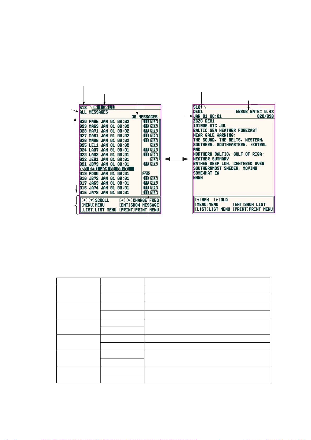
2.5 Sample Messages
Press ▲ or ▼ on the cursor pad to choose a message, and then press the ENT
key to show the detailed information for that message. The message list and
detailed message displays can be switched by pressing the ENT key.
Category of messages
(paragraph 2.11)
New
Old
Operation guide
Message list Detailed message
Frequency (paragraph 2.9)
Status icon (paragraph 2.14)
No. of saved messages
Station ID, type of message,
serial No. (two digits, paragraph 1.3)
Receiving
date
ENT key
Message icon (paragraph 2.14)
Error rate
Note 1: The operation guide at the bottom of screen shows the functions of the
keys available for use with the current screen.
Note 2: The character size can be changed. For detail, see page 2-18.
Key Display mode Function
▲▼
List Scrolls the list.
Detailed Scrolls the message.
◄►
List Switches the international and local lists.
Detailed Shows the newer (◄) or older (►) message.
MENU
List
Shows the main menu.
Detailed
ENT
List Shows the detailed message selected.
Detailed Shows the message list.
LIST
PRINT
List
Detailed
List
Detailed
Shows the list options.
Shows the print options.
2-4
Page 25
2.6 Choosing the Receive Mode
The NAVTEX menu allows you to select what station to receive, automatically,
manually. The Auto mode requires navigation data, and stations are
automatically selected according to the distance between own ship and NAVTEX
stations. If navigation data is not input, all stations are selected. The manual
mode lets you freely stations to receive. The INS mode allows you to set the
station, message and local channel from the external equipment (ex. Integrated
Navigation System, using NMK sentence) connected.
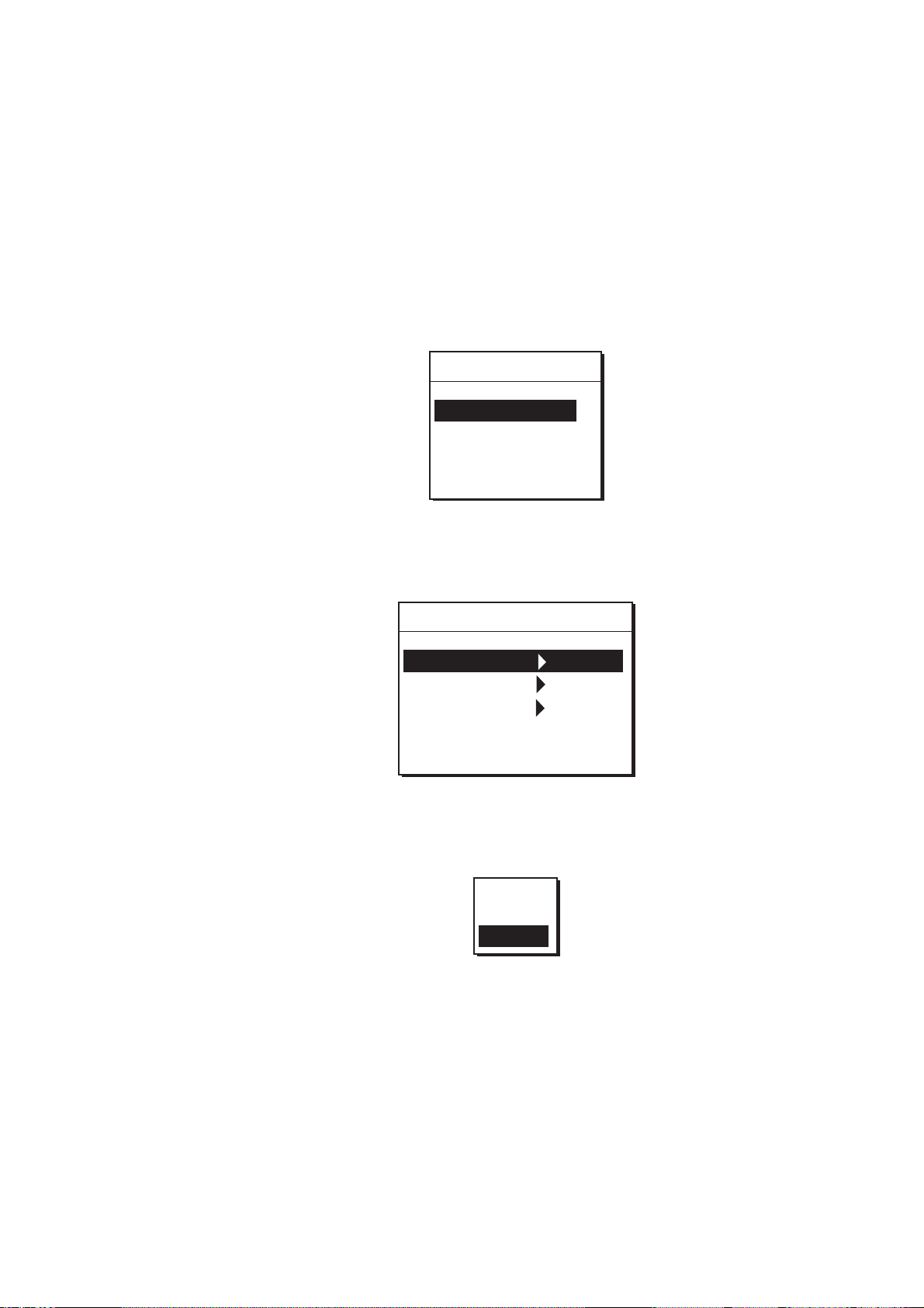
1. Press the MENU/ESC key to show the main menu.
Menu
NAVTEX
System
Display
Service
2. OPERATION
Main menu
2. Press ▲ or ▼ to choose NAVTEX.
3. Press the ENT key or ► to open the NAVTEX menu.
NAVTEX
Receive Mode Manual
Local Channel 490kHz
Auto Print All
Rcv Station & Msg
User Select Station & Msg
NAVTEX menu
4. Press ▲ or ▼ to choose Receive Mode, and then press the ENT key or ► to
show the receive mode options.
INS
Auto
Manual
Receive m ode options
5. Press ▲ or ▼ to choose INS, Auto or Manual as appropriate, and then press
the ENT key.
6. Press the MENU/ESC key several times to close the menu.
2-5
Page 26

2. OPERATION
2.7 Choosing the Local Frequency
You can choose 490 kHz or 4209.5 kHz as the local frequency. This function is
only available for the Auto and Manual modes. (See paragraph 2.6.)
1. Press the MENU/ESC key to show the main menu.
2. Press ▲ or ▼ to choose NAVTEX, and then press the ENT key or ►.
3. Press ▲ or ▼ to choose Local Channel, and then press the ENT key or ► to
show the local channel options.
490kHz
4209.5kHz
Local channel options
4. Press ▲ or ▼ to choose the frequency 490 kHz or 4209.5 kHz, and then
press the ENT key.
5. Press the MENU/ESC key several times to close the menu.
2.8 Editing the Settings for Station and Message
Stations and messages for receiving/displaying on each station (message) can
be edited as below.
Rcv Stat ion & Msg
Station
You can receive messages by station when Manual is chosen as the Receive
Mode on the NAVTEX menu.
Message
You can choose the messages to receive when Manual or Auto is chosen as the
Receive Mode on the NAVTEX menu. Note that A/B/D/L cannot be rejected.
User Select Station & Msg
Station
Choose the station to display on User Selected Messages, which is shown when
the LIST key is pressed.
Message
Choose the type of message to display on User Selected Messages, which is
shown when the LIST key is pressed.
Note 1: For messages, the alarm message is displayed always.
Note 2: When User Select is chosen as the Auto Print on NAVTEX menu, only
the messages chosen here are printed. (See paragraph 2-11.)
1. Press the MENU/ESC key to show the main menu.
2. Press ▲ or ▼ to choose NAVTEX, and then press the ENT key.
2-6
Page 27
2. OPERATION
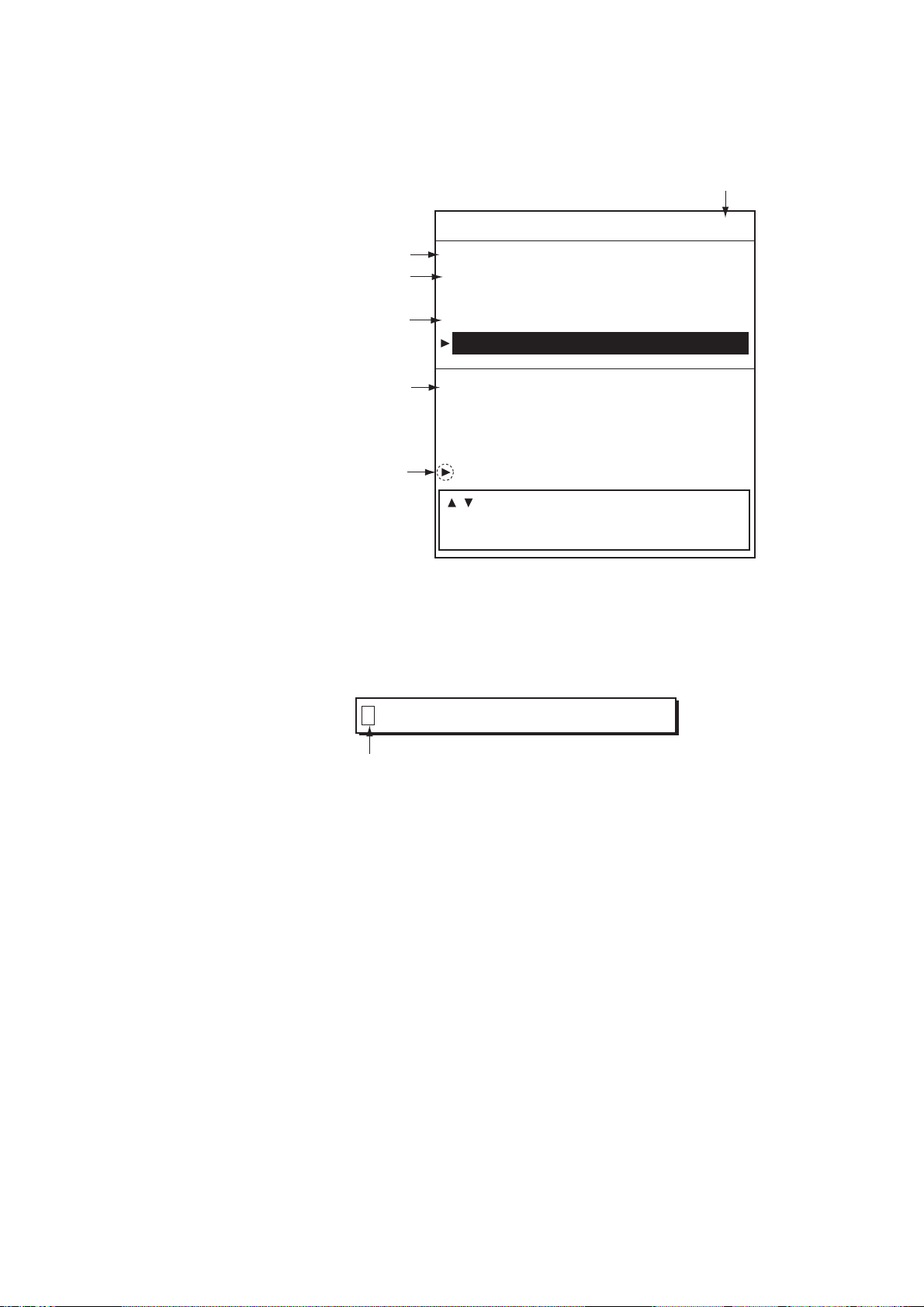
3. Press ▲ or ▼ to choose “Rcv Station & Msg” or “User Select Station & Msg”.
4. Press the ENT key to open the appropriate editing window. (Below is the Rcv
Station & Msg editing window.)
Recieve mode
Rcv Station & Msg [Auto]
Internaitional frequency
Station
Message
[518]
Station
ABCDEFGHIJKLMNOPQRSTUVWXYZ
Message
ABCDEFGHIJKLMNOPQRSTUVWXYZ
Local frequency*
[490]
Station
ABCDEFGHIJKLMNOPQRSTUVWXYZ
Message
Changeable item
ABCDEFGHIJKLMNOPQRSTUVWXYZ
[ ][ ] MOVE
[ENT] EDIT [MENU] RETURN TO MENU
*: Local channel selected at Paragraph 2.7.
Edit wi ndow (ex. Rcv S tation & M s g)
5. Press ▲ or ▼ to choose the item to edit, and then press the ENT key to
show the alphabet selection window.
ABCDEFGHIJKLMNOPQRSTUVWXYZ
Cursor
6. Press ◄ or ► to choose the alphabet desired, and then press ▲ or ▼ to
choose to receive or not.
The alphabet you have chosen not to receive is marked with “-“ (hyphen).
7. Press the ENT key
8. Repeat steps 5 through 7 to complete.
9. Press the MENU/ESC key to close the window.
2-7
Page 28

2. OPERATION
2.9 Switching the Frequency to Display
With showing the message list, you can switch the frequency to 518 kHz or 490
(or 4209.5) kHz by pressing ◄ or ► key.
Press
518
Swit c hing t he frequency to di s play
490 (4209)
2.10 Alarm Messages
The sequence of events when an alarm message is received is as shown below.
When receiving SAR (Search and Rescue) message:
The audible alarm beep sounds, and the SAR message is shown. Note that All
Messages list appears if other list option is chosen when the ENT key is pressed.
(See paragraph 2.11.)
When receiving WARNING message (A/B/L) :
When the Warn Msg Alm on System menu is set to On, the audible alarm
sounds and the message for receiving appears.
Silenci ng audible alarm
Press any key (except
key).
2-8
Page 29

2.11 Processing Messages
Choosing messages to display
You can choose which category of messages to display: All, Alarm, User
Selected and Good messages.
1. With the message list or detailed message shown, press the LIST key to
show the list options.
All Messages
Alarm Messages
User Messages
Good Messages
Lock Message
List options
2. Press ▲ or ▼ to choose the item.
All Messages: Shows all messages received.
Alarm Messa ge s: Shows only SAR/WARNING messages.
User Selected Messages: Shows messages arranged at User Select Station &
Msg on NAVTEX menu.
Good Messages: Shows messages whose error rate is less than 4%.
3. Press the ENT key to close the window.
The list chosen at step 2 appears.
Note: When the following messages appear, set the List window to All Messages
to show.
Urgent message:
“Message not chosen for display received; it is a int’l (or local) 00 message.
Choose “All Message” (LIST menu) to display.”
Normal messag e:
Int’l (or local) message not chosen for display received. Choose “All
Message” (LIST menu) to display.”
2. OPERATION
2-9
Page 30

2. OPERATION
Protecting message from deleting
Messages are automatically deleted from the memory under the following
conditions.
-66 hours passed from the moment when received.
-Older than No. 200
To prevent a message from being deleted, do the follows;
1. Choose the message at the list display.
2. Press the LIST key to show the list options.
3. Choose Lock Message from the list window.
Note 1: To unlock a message, choose it and then select Unlock Message in the
Note 2: When you unlock a message which was received 66 hours ago or a
Note 3: Maximum each 50 messages for International and local (or 25% of each
All Messages
Alarm Messages
User Messages
Good Messages
Lock Message
List options
The protect icon (
list window. (The protect icon disappears.)
message that is older than No. 200, it will be deleted promptly when
unlocked.
memory) can be protected.
) appears next to the message selected.
2.12 Printing Messages
Received messages can be printed automatically or manually, from the built-in
printer (NX-700A) or external printer (NX-700B).
Printing all messages displayed
All messages chosen on paragraph 2.11 can be printed out.
1. Press the PRINT key with showing all messages.
Print
Cancel Print
2. Press ▲ or ▼ to choose “Print”.
3. Press the ENT key to print.
Note: When a message is received while printing some messages, the new one
cannot be printed.
Print opt ions
2-10
Page 31

2. OPERATION
Printing each message
1. Press ▲ or ▼ to choose the desired message from the list.
2. Press the ENT key to show the detailed information.
3. Press the PRINT key.
4. Press ▲or ▼ to choose “Print” from the window.
5. Press the ENT key to print.
Printing messages automati cally
When receiving a message, it can be printed out immediately.
1. Press the MENU/ESC key to open the main menu.
2. Press ▲ or ▼ to choose NAVTEX, and then press the ENT key to show the
NAVTEX menu.
3. Press ▲ or ▼ to choose Auto Print, and then press the ENT key to open the
auto print options.
Off
All
User Select
Auto print options
4. Press ▲ or ▼ to choose All, User Select or Off as appropriate.
All: Prints all messages when receiving.
User Select: Prints only the specified messages at User Select Station & Msg
on the NAVTEX menu when receving.
Off: All messages are not printed automatically.
5. Press the ENT key.
6. Pres the MENU/ESC key several times to close the menu.
Canceling printing
When a menu is displayed, you cannot cancel the printing.
1. Press the PRINT key while showing the messages to open the print window.
2. Press ▼ to choose “Cancel Print” and then press the ENT key.
2-1 1
Page 32

2. OPERATION
2.13 Editing the NAVTEX Station List
Maximum 300 NAVTEX stations can be registered into the memory.
Note: To cancel editing of a NAVTEX station, press the MENU/ESC key. The
message “Exit without saving?” appears. Choose “Yes”, and then press
ENT key.
Adding NAVTEX station
You may add a NAVTEX station to the NAVTEX station list as follows:
1. Press the MENU/ESC key to show the main menu.
2. Press ▲ or ▼ to choose Service, and then press the ENT key.
Service
INS Input Speed 4800bps
INS Output Speed 4800bps
Print Header On
Edit Station List
Default Setting
Test
Rcv Monitor
Service menu
3. Press ▲ or ▼ to choose Edit Station List, and then press the ENT key.
Frequency
NAV Area
Station name
518kHz
NavArea 01
[ New ]
Oostende T, - , Tallinn U, - , Reykjavik Radio R,- , Valentia W,- , Malin Head Q,- , Niton K, - , Den Helder P, - , Bodo Radio B, - , Rogaland Radio L, - , Vardoe Radio V, - , Svalbard A, - , -
[ ][ ] CHANGE NAVAREA
[LIST] CHANGE FREQ
[ENT] EDIT [MENU] RETURN TO MENU
Edit station list display
4. Confirm that New is chosen, and then press the ENT key to show the
addition window appears.
2-12
Page 33

2. OPERATION
NAV Area
Station Name
Latitude
Longitude
NavArea 1
Station
Latitude 0 00'N
Longitude 0 00'E
518kHz ID1: - ID2: - ID3: -
Station ID
490kHz ID1: - ID2: - ID3: -
4209.5kHz ID1: - ID2: - ID3: -
Sertvice Area
Range 400nm
Save data ?
New addition window
5. Confirm that NavArea is chosen, and then press the ENT key to show the
area No. window.
6. Press ▲ or ▼ to choose a Nav area No. (1 to 16, and EXT), and then press
the ENT key.
For NAV area No., see paragraph 1.4. EXT is reserved for future use.
7. Confirm that Station is chosen, and then press ENT key.
8. Enter a station name (Max. 18 characters), and then press the ENT key.
a) Press ▲ or ▼ to choose a character. Each press of ▲ shows A -> … -> Z ->
a -> … -> z -> 0 -> … -> 9 -> _ -> - -> space in that sequence.
b) Press ► to move the cursor to next digit.
c) Repeat steps a) and b) to complete the station name.
9. Confirm that Latitude is chosen, and then press the ENT key.
10. Enter the latitude for station, and then press the ENT key.
Use ▲ or ▼ to switch to North and South.
11. Confirm that Longitude is chosen, and then press the ENT key.
12. Enter the longitude for station, and then pres the ENT key.
Use ▲ or ▼ to switch to East and West.
13. Choose 518kHz, 490kHz or 4209.5kHz, and then press the ENT key.
14. Enter the station ID (A to Z), and then press the ENT key.
For multiple stations, fill in ID2 and ID3.
15. Confirm that Range is chosen, and then press the ENT key.
16. Enter the service area (1 to 999 nm), and then press the ENT key.
17. Confirm that Save data? is chosen, and then press the ENT key.
The message “Save new station?” appears.
18. Press ◄ to choose “Yes”, and then press ENT key to close the new addition
window disappears.
Note: If the station ID was not entered at step 14, the message “Enter ID
data.” appears. Press any key, and then enter the station ID.
19. To enter another NAVTEX station, repeat steps 4 through 18.
20. Press the MENU/ESC key several times to close the menu.
2-13
Page 34

2. OPERATION
Editing NAVTEX station
Existing NAVTEX station may be edited as follows:
1. Press the MENU/ESC key to show the main menu.
2. Press ▲ or ▼ to choose Service, and then press the ENT key.
3. Press ▲ or ▼ to choose Edit Station List, and then press the ENT key.
4. Press ◄ or ► to choose the NAV area to be changed (01 to 16, EXT).
5. Press the LIST key to choose the frequency to be changed (518kHz, 490kHz
6. Press ▲ or ▼ to choose the station, and then press the ENT key.
7. Press ▲ to choose “Edit”, and then press ENT key to show the edit window
or 4209.5kHz).
appears.
NAV Area
Station Name
Longitude
Service Area
Latitude
Station ID
Edit
Delete
Oostende
NavArea 1
Station Oostende
Latitude 51 11'N
Longitude 2 48'E
518kHz ID1: T ID2: - ID3: 490kHz ID1: - ID2: - ID3: -
4209.5kHz ID1: A ID2: - ID3: Range 55nm
Save data ?
Edit wi ndow (Ex. NAVTEX station Oostende)
8. Edit data as appropriate.
9. Confirm that Save station? is chosen, and then press the ENT key.
10. Press ◄ to choose “YES”, and then press the ENT key to erase the edit
window.
11. Press the MENU/ESC key several times to close the menu.
Deleting NAVTEX stations
You may delete unnecessary NAVTEX stations as follows:
1. Press the MENU/ESC key to show the main menu.
2. Press ▲ or ▼ to choose Service, and then press the ENT key.
3. Press ▲ or ▼ to choose Edit Station List, and then press the ENT key.
4. Press ◄ or ► to choose the NAV area to be deleted. (01 to 16, EXT).
5. Press the LIST key to choose the frequency to be deleted (518kHz, 490kHz
or 4209.5kHz).
6. Press ▲ or ▼ to choose the station name to be deleted, and then press ENT
key.
The item window appears.
2-14
Page 35

7. Press ▲ or ▼ to choose Delete, and then press the ENT key.
The message “Delete station?” appears.
8. Press ◄ to choose “Yes”, and then press the ENT key to close the edit
window.
9. Press the MENU/ESC key several times to close the menu.
2.14 Icons
The NX-700 shows various icons to denote equipment status, and these are as
shown in the table below.
Icon Status Meaning
Status icon (shown at the tip of display)
Edit
Delete
2. OPERATION
Blinking
L1
Blinking
L2
Blinking
I Blinking
L1 Blinking
L2
Lighting
X
Lighting
P
R
Lighting While printing.
Message icon (shown next to messages)
NEW
Blinking
Lighting
Shows that an International frequency (518 kHz)
message has not been read.
Shows that a Local frequency message has not
been read.
L1: 490 kHz, L2: 4209.5 kHz
Appears while receiving a message.
I: International frequency (518 kHz)
L1: 490 kHz
L2: 4209.5 kHz
Displayed when the voltage of the internal battery is
low. The message “Battery error” also appears on
the display.
Print error (no paper, not connected to the printer,
etc.). The message “Printer error” also appears on
the display.
Displayed when message is displayed for the first
time.
(This icon disappeared after showing the detail or 24
hours has passed.)
SAR Lighting Displayed when message type D (SAR) is displayed.
!!
Lighting Protected message
Lighting
Appears when message type A, B or L (Warning) is
displayed.
2-15
Page 36

2. OPERATION
2.15 Messages List
In addition to the message “Received new local (int’l) msg.” the following
message-related messages may appear on the display.
Message Meaning Remedy
New message received.
Oldest message deleted to
free up memory.
Same message with lower
error rate received.
Currently displayed
message will be deleted.
Term of validity expired.
Currently displayed
message will be deleted.
Message not chosen for
display received; it is a int’l
00 message. Choose “All
Message”(LIST menu) to
display.
Message not chosen for
display received; it is a
local 00 message. Choose
“All Message”(LIST menu)
to display.
Int’l message not chosen
for display received.
Choose “All
Message”(LIST menu) to
display.
Local message not chosen
for display received.
Choose “All
Message”(LIST menu) to
display.
Appears when the oldest
message is deleted to
make space for the latest
one.
Appears when two
messages have the
same ID are received
and the latter’s error rate
is lower than the former.
Appears when 66 hours
has passed after
receiving the currently
displayed message.
Appears when receiving
an international message
not specified for display
(00) at the SELECT
MESSAGES display.
Appears when receiving
a local message not
specified for display (00)
at the SELECT
MESSAGES display.
Appears when receiving
an international message
not specified for display
(Normal) at the SELECT
MESSAGES display.
Appears when receiving
a local message not
specified for display
(Normal) at the SELECT
MESSAGES display.
Press any key.
Press any key.
Press any key.
Press any key, and then
choose All Message in
the List window.
2-16
Page 37

2.16 Other Functions
This paragraph describes the various options which allow you to set up your unit
to suit your needs.
NAVTEX menu
Item Description Setting
Receive
Mode
Local
Channel
Auto Print Chooses the message to print
Rcv Station &
Msg
User Select
Station &
Msg
System menu
Chooses the receiving mode. (See
paragraph 2.6.)
Chooses the local channel. 490kHz, 4209.5kHz
automatically. (See paragraph 2.12.)
Receives messages in the category.
Sets the station and type of message to
be shown on the SELECT MESSAGES
display.
2. OPERATION
INS, Auto, Manual
Off, All, User Select
-
-
Item Description Setting
Warn Msg Alm
Signal Monitor
Key Beep Turns key beep on/off. On, Off
Time Offset
Units
Printer Sets the printer type. (See paragraph 4.6.)
Turns the audible alarm on/off when receiving a
Warning message (A, B, and L).
Turns the audible alarm for monitoring of Rx
signal on/off.
Off: Disables monitoring.
Int’l: Monitors international frequency.
Local: Monitors local frequency.
If a GPS receiver feeds nav data to the NAVTEX,
you may use local time instead of UTC time.
Enter the time difference between local time and
UTC time.
Chooses units of measurement (distance and
ship speed) to be shown on the User Display.
On, Off
Off, Int’l, Local
-13:30 to
+13:30
nm, kt,
km, km/h,
mi, mi/h
None,
NX-700A,
Upright,
Inverted
2-17
Page 38

2. OPERATION
Display menu
Item Description Setting
Selects the speed of scrolling by pressing ▲ or ▼.
Slow: Scrolls by one line.
Scrolling
Fast: Scrolls by half of screen.
Skips t o $$:
Scrolls line by line in list display; Skips to $$ position in detailed
display.
Small,
Font Size Selects the size of characters.
Medium,
Large
Time Display Selects the time format. 24 hour,
12 hour
Selects the date format.
Date Display
MMM DD YYY,
DD MMM YYYY,
YYYY MMM DD
Selects the type of data as user display to be shown at the
bottom of the display.
Nav Data
Slow, Fast,
Skip to $$
Date
Own ship's
position
Ship's speed
User Display
MAY 07 2005 00:00:18
12 34. 001 ' N
123 45. 001 ' E
SOG 1. 6 kt
[ ][ ] SCROLL [ ][ ] CHANGE FREQ
[MENU] MENU [ENT]
[LIST] LIST MENU [PRINT] PRINT MENU
COG 56. 9
SHOW MESSAGE
Course
Nav Data,
Distance
Distance
Distance between the positions shown in the message and
own ship's when receiving.
DISTANCE 23.4nm
[ ][ ] SCROLL [ ][ ] CHANGE FREQ
[MENU] MENU [ENT]
[LIST] LIST MENU [PRINT] PRINT MENU
SHOW MESSAGE
Speed
Display
Selects the speed format to be displayed.
SOG: Speed Over Ground
STW: Speed Through Water
SOG, STW
Contrast Sets the display contrast. 0 to 9
Off,
2-18
Page 39

2. OPERATION
Service menu
Item Description Setting
4800,
INS
Input
Speed
Selects the data transmission speed at which to input data
from INS.
9600,
19200,
38400
bps
4800,
INS
Output
Speed
Selects the data transmission speed to output data to the INS.
9600,
19200,
38400
bps
Turns the header (Own ship’s position, date, frequency, error
rate and distance information when receiving a message) for
printing on/off.
518kHz Error Rate: 0.0%
Received MAY 07 2005 01:12:53
Position 34 28'N 134 03'E
Distance 23.4nm
ZCZC AA10
Header
On, Off
Print
Header
Edit
Receiving date
Own ship's poisition
when receiving
Distance between the positions shown in the messasge
and own ship's when receiving.
Edits/deletes stations. (See paragraph 2.13.) -
Station
List
Default
Restores all default settings. (See paragraph 3.5.)
Settings
Test Starts the diagnostic test. (See paragraph 3.4.) -
Shows the status for International and Local receiving.
International
message
-
Rcv
Monitor
Local message
-
2-19
Page 40

2. OPERATION
This page is intentionally left be blank.
2-20
Page 41

3. MAINTENANCE & TROUBLESHOOTING
This chapter provides information necessary for keeping your unit in good
working order and remedying simple problems.
WARNINGWARNING
Do not open the equipment.
Hazardous voltage which can
cause electrical shock exists
inside the equipment. Only
qualified personnel should
work inside the equipment.
3.1 Maintenance
Regular maintenance is important for optimum performance. A maintenance
program should be established and should at least include the items shown in
the table below.
Maint enanc e pr ogram
Item Check point Remedy
Display unit connectors Check for tight connection. Tighten loosened connectors.
LCD The LCD will, in time,
accumulate a coating of dust
which tends to dim the picture.
Wipe LCD lightly with soft
cloth to remove dust.
Wipe the LCD carefully to
prevent scratching, using
tissue paper and an LCD
cleaner. To remove dirt or salt
deposits, use an LCD cleaner,
wiping slowly with tissue
paper so as to dissolve the dirt
or salt. Change paper
frequently so the salt or dirt
will not scratch the LCD. Do
not use solvents such as
thinner, acetone or benzene
for cleaning.
Ground terminal Check for tight connection and
corrosion.
Clean or replace ground wire
as necessary.
3-1
Page 42

3. MAINTENANCE & TROUBLESHOOTING
3.2 Replacement of Fuse, Battery and Thermal
Paper
Fuse
The fuse inside the receiver unit protects the equipment from overcurrent or
reverse polarity. If the fuse blows, contact your dealer about replacement.
Name Type Code No.
Fuse FGMB 2A 125V 000-103-165
WARNING
Use the proper fuse.
Use of a wrong fuse can result in damage
to the equipment or cause fire.
Battery
A battery is installed inside the display unit, and it preserves data when the
power is turned off. The life of the battery is about 5-10 years, and its voltage is
checked when the power is turned on. When its voltage is low, the BATTERY
(
dealer to request replacement of the battery.
Note: When the battery is dead, all default settings are restored.
) icon appears on the display to alert you. When this happens, contact your
Name Type Code No.
BATT CR2450-F2ST2L 000-144-941
WARNING
Ensure battery polarity is correct.
Wrong polarity may cause the batteries to
explode.
3-2
LCD Display
The life of the LCD is approx. 20,000 hour. When the LCD has expired, the
brilliance cannot be raised.
Page 43

3. MAINTENANCE & TROUBLESHOOTING
Thermal paper (NX-700A o nly)
When the thermal paper runs out completely, the message “Printer error” (center
X
of screen) and the
icon (at the right-hand top corner) appear. Replace the
paper as follows.
Name Type Code No.
Thermal paper TP058-30CL 000-154-047
1. Turn off the power.
2. Press the button shown below to open the paper holder cover.
Eject button
3. Peel the tape from the end of new paper.
Tape
4. Set the new paper in the paper container in the direction shown below.
Paper holder
New paper
Paper holder cover
5. Pull the end of the paper by 2 to 3 cm (as shown above), and then close the
cover.
3-3
Page 44

3. MAINTENANCE & TROUBLESHOOTING
3.3 Troubleshooting
This section provides simple troubleshooting procedures which the user can
follow to restore normal operation. If you cannot restore normal operation do not
attempt to check inside the unit. Any trouble should be referred to a qualified
technician.
If . . . then . . .
you cannot turn on the power
the equipment receives unwanted
messages.
NAVTEX signal cannot be received.
paper does not advance. (NX-700A only) load paper correctly.
paper feeds but no recording. (NX-700A
only)
paper has darkened. (NX-700A only)
the recording is not proper for the external
printer. (NX-700B only)
-ask serviceman to replace the blown
fuse.
-check battery for proper voltage
output.
confirm that “Manual” is chosen at
Receive Mode on the NAVTEX menu.
check equipment by the diagnostic
test.
check the broadcasting schedule.
check that the D-sub connector is
firmly fastened.
check that the antenna cable is firmly
fastened.
check if correct thermal paper is being
used.
keep the paper in a well-ventilated and
cool place.
check the setting of Printer on the
System menu.
check the printer cable.
check that the power of printer is
turned on and status is
“SELET/READY”.
check that the printer is available.
check that paper is set properly.
3-4
Page 45

3.4 Diagnostics
The memory test checks ROM, RAM, data port, battery, keyboard and LCD for
proper operation and displays program version numbers.
1. Press the MENU/ESC key to open the main menu.
2. Press ▼ to choose Service, and then press the ENT key.
3. Press ▲ or ▼ to choose Test, and then press the ENT key.
The message “Start test?” appears.
4. Press ◄ to choose “Yes”, and then press the ENT key.
3. MAINTENANCE & TROUBLESHOOTING
Memory Test
Program No : 0850193-01.*
Boot : 0850192-01.*
ROM : OK
SRAM : OK
DRAM : OK
CPU RAM : OK
EEPROM : OK
Battery : OK (3.2V)
Hit any key.
*: Program version no.
Memory te s t
For any NG (No Good), contact your dealer.
5. When the message “Hit any key.” appears at the bottom of screen, press any
key (except
key) to show the key test screen.
Ke y Test
If there is no operation for
10 s, the screen changes.
Key test
6. Press each key (except
A key is functioning properly if its on-screen location fills in black when the key is
pressed.
key) one by one.
7. After all keys have been tested or no key is pressed after 10 seconds, the
equipment starts the LCD test by showing the white and black display (level
0 to 9).
3-5
Page 46

3. MAINTENANCE & TROUBLESHOOTING
8. When the message “Hit any key” appears on the screen, press any key
(except
The alarm for receiving monitor sounds while the Rx test is being conducted.
Also the test message is printed when the item other than “None” at Printer on
System menu.
key) to show the Rx test screen.
Rx test
9. When the message “Hit any key.” appears on the screen, press any key
(except
10. Press the MENU/ESC key several times to close the menu.
key) or wait for one minute with no operation to finish.
3.5 Restoring all Default Settings
This operation restores all default settings. The following two settings, however,
are not disturbed.
-Received messages
-NAVTEX stations list (See paragraph 2.13.)
1. Press the MENU/ESC key to show the main menu.
2. Press ▼ to choose Service, and then press the ENT key.
3. Press ▲ or ▼ to choose Default Setting, and then press ENT key.
The message “Restore default settings?” appears.
4. Press ◄ to choose “Yes”, and then press the ENT key.
The Service menu appears.
5. Press the MENU/ESC key several times to close the menu.
3-6
Page 47

4. INSTALLATION
4.1 Display Unit
The display unit can be installed on a tabletop, on the overhead, or in a panel.
Refer to the outline drawings at the back of this manual for installation
instructions. When selecting a mounting location, keep in mind the following
points.
• Locate the unit away from exhaust pipes and vents.
• Locate it of direct sunlight, (or in a suitable, ventilated enclosure) to prevent
heat which can build up inside the cabinet.
• The mounting location should be well ventilated.
• Mount the unit where shock and vibration are minimal.
• Allow sufficient maintenance space at the sides and rear of the unit and leave
sufficient slack in cables, to facilitate maintenance and servicing.
• Compass safe distances are:
NX-700A (Standard: 1.45 m, Steering: 0.95 m)
NX-700B (Standard: 0.30 m, Steering: 0.30 m)
T abletop, overhead mounting
1. Fix the hanger by using four self-tapping screws (5x20).
2. Screw knob bolts in display unit, set it to the hanger, and tighten the knob
bolts.
Note: For the overhead mounting, reinforce the mounting location for the weight
of the display unit (NX-700A: 3.3 kg, NX-700B: 0.7 kg) and secure the
hanger, with bolts, nuts and washers (local supply).
NX-700A
NX-700B
4-1
Page 48

4. INSTALLATION
Flush mounting
The display unit can be installed flush mounted in a console or panel by using
the optional flush mount kit.
.
(For NX-700A)
Type: OP08-19 Code No.: 004-514-810
Name Type Code No. Qty Remarks
Mounting metal 08-023-1019 100-326-960 1
Self-tapping screw 5X20 000-802-081 6
Hex. bolt M8x15 000-862-144 2
Spring washer M8 000-864-262 2
1. Cut out a hole with dimensions as shown below in the mounting location.
30+1
168+0.5
284+0.5
156+1
7
275+1
7
4
Fixing hole
2. Attach the fixing metal to the display unit with two hex. bolts (M8x15,
supplied with optional kit) and spring washers (supplied with optional kit).
3. Fasten six self-tapping screws to fix the display unit to the mounting location.
(For NX-700B)
Type: OP08-20 Code No.: 004-514-820
Name Type Code No. Qty Remarks
Mounting metal 08-023-2011 100-327-010 1
Self-tapping screw 5x20 000-802-081 4
Pan head screw M4x12 000-802-130 4
1. Cut out a hole with dimensions as shown below in the mounting location.
144+1
155+0.5
156+1
4-2
155+0.5
4
Fixing hole
2. Attach the fixing metal to the display unit with four pan head screws (M4X12,
supplied with the optional kit).
3. Fasten four self-tapping screws (supplied with the optional kit) to fix the
display unit to the mounting location.
Page 49

4. INSTALLATION
4.2 Receiver Unit
General mounting considerations
• The mounting location should be well ventilated and dry.
• The unit can be mounted on bulkhead or the desk.
• Secure the maintenance space shown in drawing at the back of this manual
for ease of maintenance and service.
• Compass safe distances are:
Standard: 1.15 m, Steering: 0.75 m
Mounting Method
Fasten the receiver unit with four self-tapping screws (5x20, supplied as
installation material). For bulkhead mounting, do the follows.
1. Tighten lower self-tapping screws so there is 5 mm clearance between
bottom of screw head and bulkhead.
2. Hook the receiver unit on the lower screws.
3. Tighten upper screws followed by the lower screws.
Fixing hole 2- 6
205+1
8
210+1
6
210+1
Notch
4-3
Page 50

4. INSTALLATION
4.3 Antenna Unit
Mounting considerations
Install the antenna unit referring to the antenna installation diagram at the back
of this manual. When selecting a mounting location for the antenna unit, keep in
mind the following points:
• Do not shorten the antenna cable.
• The NX-700 contains a very sensitive receiver. To avoid mutual interface with
other radio equipment, do not install this unit near an SSB/VHF/CB
radiotelephone.
Coat here with silicone sealant to
prevent breakage of the cable by
vibration.
Wrap the vinyl sheet to prevent
the breakage of the cable, and
then fix the hose clamp.
4-4
Page 51

4.4 Printer (NX-700B only)
Prepare the printer by locally as shown below for the NX-700B.
-8 bit parallel Centronics interface, or serial RS-232C
-Serial printer
-Baud Rate: 9600 bps
-Character length: 8 bit
-Parity: No
-Flow control: Xon/Xoff
-32 characters/line or more
4.5 Wiring
4. INSTALLATION
Ground wire
IV-1.25sq (Local supply)
DSUB25P-DSUB25P cable
Ground wire
IV-1.25sq (Local supply)
(Local supply)
Display unit
NX-700A or B
(3m)
Power cable
DPYC-2.5
Antenna ubit
NX-7H
Antenna cable
04S4168 10/20/30/40/50m
Receiver unit
NX-7001
-INS or Navigator
-Printer (for NX-700B only)
-Alarm
12-24VDC
4-5
Page 52

4. INSTALLATION
Receiver unit
All cables are gathered to the receiver unit. Connect cables at inside of the
receiver unit as shown below.
TB401
(+)
RCV Board
08P3227
TB402
(-)
J401
J402*
1 2 3 4 5 6
J403
1 2 3 4 5 6 7 8
Antenna cable
(to Antenna unit)
DPYC-2.5
(to ship's battery)
TTYCS-1Q
(to Navigator
Printer cable
(to Printer, NX-700B only)
or INS )
DPYC-1.5
(to External alarm)
DSUB25P-DSUB25P-3M cable
(to Display unit)
Receiver unit, inside view
Use the following JIS cable (Japan Industrial Standard) or equivalent to connect
power source, INS and external alarm appropriately.
DPYC-2.5
φ =
12.5 mm
Conductor
S = 2.5 mm
φ = 2.01 mm
Armor
Sheath
2
DPYC-1.5
φ =
11.7 mm
Conductor
S = 1.5 mm
φ = 1.56 mm
Armor
Sheath
2
TTYCS-1Q (Four core twisted)
Armor
Sheath
φ = 11.3 mm
Conductor
S = 0.75 mm
φ = 1.11 mm
Shield
2
4-6
For printer, use the cable supplied with the printer.
Page 53

Fabricate these cables as below to connect to the receiver unit.
DPYC-1.5 (For external alarm)
Vinyl sheath
25 mm
100 mm
4. INSTALLATION
5 mm
Scrape the paint off the cable
where the cable contacts the cable clamp.
TTYCS-1Q (For Navigator or INS)
Scrape the paint off the cable
where the cable contacts the cable clamp.
DPYC-2.5 (For ship’s battery)
25 mm
25 mm
Soldering
Shield
Soldering
Vinyl sheath
100 mm
Vinyl wire
5 mm
100 mm
Vinyl wire
5 mm
Crimp-on lug
(M4, local supply)
Vinyl sheath
Scrape the paint off the cable
where the cable contacts the cable clamp.
How to use J402 and 403 connector
1. Insert the terminal opener (attached in the receiver unit) into the connector.
2. Insert a wire in terminal while pressing and holding the terminal opener.
3. Release the terminal opener. Pull wire to confirm that it is connected firmly.
Terminal opener
Wire
4-7
Page 54

4. INSTALLATION
Antenna cable
Be sure to leave some slack in the cable for future service and maintenance.
For RG-10/UY, RG-214 cable
When using the coaxial cable, type RG-10/UY or RG-214, attach the FM-MP-7
connector (supplied as installation material) or PL-259 (loc al supply) as below.
1. Remove the sheath by 30 mm.
2. Bare 23 mm of the center conductor. Trim braided shield by 5 mm and tin.
3. Slide coupling ring onto cable.
4. Screw the plug assembly on the cable.
5. Solder plug assembly to braided shield through solder holes. Solder contact
sleeve to conductor.
6. Screw coupling ring into plug assembly.
Sheath
Braided shield
5 mm
30 mm
2 mm
Conductor
Insulator
Plug assembly
Coupling ring
Contact sleeve
Solder both
sides of hole.
Cut conductor here.
Note: When the RG-214 cable is used, care must be exercised to p revent
damage to the cable as it has no armor.
Solder here
.
4-8
Page 55

4. INSTALLATION
Extending antenna cable length
When connecting two cables for extension, use optional extension cable kit
OP-04-2.
Code No.: 000-041-174 (10 m), 000-041-175 (20 m), 000-041-176 (30 m),
000-041-177 (40 m), 000-041-178 (50 m)
Name Type Code No. Qty Remarks
005-948-320 10 m w/connectors
005-948-330 20 m w/connectors
Cable assy 04S4168
Connector FMA-1 000-152-964-10 1
Insulating tape U tape 0.5x19x5M 000-800-985 1
005-948-340 30 m w/connectors
005-948-350 40 m w/connectors
005-948-360
1
50 m w/connectors
OP04-2
To Receiver unit
FMA-1 connector
Grounding
The ground wire (local supply) should be 1.25 sq or larger. The ground wire
should be as short as possible.
4-9
Page 56

4. INSTALLATION
4.6 Setting of Printer
After the connection completely, the setting of printer should be done for
NX-700B as shown below. (For NX-700A, use the default setting as is.)
1. Press the
2. Press the MENU key to show the main menu.
3. Press ▼ to choose System, and then press the ENT key or ► to activate the
System menu.
key to turn the power on.
Menu
NAVTEX
System
Display
Service
System
Warn Msg Alm Off
Signal Monitor Off
Key Beep Off
Time Offset +00:00
Units nm, kt
Printer NX-700A
4. Press ▼ to choose Printer, and then press the ENT key or ► to show the
item window.
None
NX-700A
Upright
Inverted
5. Press ▲ or ▼ to choose the appropriate setting, and then press the ENT
key.
None: When no printer is connected.
NX-700A: For NX-700A only.
Upright: When NX-700B is connected to an upright-type printer which ejects
paper in bottom to top direction.
Inverted: When NX-700B is connected to a bulkhead mount printer which ejects
paper in top to bottom direction.
6. Press the MENU key several times to close the menu.
4-10
Page 57

4.7 Digital Interfacing
This equipment can receive navigation data in IEC 61162-1 Ed2/2 format.
Priority
TIME&DATE ZDA
L/L GNS > GGA > RMC > GLL
SOG VTG > VBW > RMC
STW VHW > VBW
COG VTG > RMC
Input data sentence description
GGA: GPS position fixing condition
$--GGA,hhmmss.ss,llll.lll,a,yyyyy.yyy,a,x,xx,x.x,x.x,M,x.x,M,x.x,xxxx*hh<CR><LF>
| | | | | | | | | | | | | | |
| | | | | | | | | | | | | | +-- 11
| | | | | | | | | | | | | +---- 10
| | | | | | | | | | | | +--------- 9
| | | | | | | | | | +---+------------ 8
| | | | | | | | +---+------------------ 7
| | | | | | | +------------------------- 6
| | | | | | +---------------------------- 5
| | | | | +------------------------------- 4
| | | +----+--------------------------------- 3
| +---+--------------------------------------------- 2
+------------------------------------------------------------- 1
4. INSTALLATION
1. UTC of position
2. Latitude, N/S
3. Longitude, E/W
4. GPS quality indicator (see note)
5. Number of satellite in use,00-12, may be different from the number in view
6. Horizontal dilution of precision
7. Antenna altitude above/below mean sealevel, m
8. Geoidal separation, m
9. Age of differential GPS data
10. Differential reference station ID, 0000-1023
11. Checksum
NOTE
0 = fix not available or invalid
1 = GPS SPS mode, fix valid
2 = differential GPS, SPS mode, fix valid
3 = GPS PPS mode, fix valid
4 = Real Time Kinetic. Satellite system used in RTK mode with fixed integers
5 = Float RTK. Satellite system used in RTK mode with floating fingers
6 = Estimated (dead reckoning) mode
7 = Manual input mode
8 = Simulator mode
The GPS quality indicator shall not be a null field.
4-1 1
Page 58

4. INSTALLATION
GLL: Latitude and longitude
$--GLL,llll.lll,a,yyyyy.yyy,a,hhmmss.ss,A,a*hh<CR><LF>
| | | | | | | |
| | | | | | | +------- 6
| | | | | | +--------- 5
| | | | | +----------- 4
| | | | +---------------- 3
| | +------+----------------------- 2
+---+----------------------------------- 1
1. Latitude, N/S
2. Longitude, E/W
3. UTC of position
4. Status: A=data valid, V=data invalid
5. Mode indicator (see note)
6. Checksum
NOTE Positioning system Mode indicator:
A = Autonomous
D = Differential
E = Estimated (dead reckoning)
M = Manual input
S = Simulator
N = Data not valid
The Mode indicator field supplements the Status field. The Status field shall be
set to V=invalid for all values of Operating Mode except for A=Autonomous and
D=Differential. The positioning system Mode indicator and Status field shall not
be null fields.
4-12
Page 59

RMC: Recommend Minimum Specific G NS S Data
$--RMC,hhmmss.ss,A,llll.lll,a,yyyyy.yyy,a,x.x,x.x,xxxxxx,x.x,a,a*hh<CR><LF>
| | | | | | | | | | | | |
| | | | | | | | | | | | +--- 10
| | | | | | | | | | | +----- 9
| | | | | | | | | +--+------- 8
| | | | | | | | +--------------- 7
| | | | | | | +--------------------- 6
| | | | | | +------------------------- 5
| | | | +---+---------------------------- 4
| | +---+---------------------------------------- 3
| +--------------------------------------------------- 2
+---------------------------------------------------------- 1
1. UTC of position fix
2. Status: A=data valid, V=navigation receiver warning
3. Latitude, N/S
4. Longitude, E/W
5. Speed over ground, knots
6. Course over ground, degrees true
7. Date: dd/mm/yy
8. Magnetic variation, degrees E/W
9. Mode indicator (see note)
10. Checksum
4. INSTALLATION
NOTE Positioning system Mode indicator:
A = Autonomous
D = Differential
E = Estimated (dead reckoning)
M = Manual input
S = Simulator
N = Data not valid
The Mode indicator field supplements the Status field. The Status field
shall be set to V=invalid for all values of Operating Mode except for
A=Autonomous and D=Differential. The positioning system Mode indicator
and Status field shall not be null fields.
4-13
Page 60

4. INSTALLATION
ZDA: Time and date
$--ZDA,hhmmss.ss,xx,xx,xxxx,xx,xx*hh<CR><LF>
| | | | | | |
| | | | | | +--------- 7
| | | | | +----------- 6
| | | | +-------------- 5
| | | +------------------ 4
| | +---------------------- 3
| +------------------------- 2
+--------------------------------- 1
1. UTC
2. Day, 01 to 31(UTC)
3. Month, 01 to 12(UTC)
4. Year(UTC)
5. Local zone hours, 00h to +-13h
6. Local zone minutes, 00 to +59
as local hours
7. Checksum
4-14
Page 61

4. INSTALLATION
NRQ: Request NAVTEX messages
Command to request specific NAVTEX message(s) to be sent to IBS port. Messages may be
sent in any order. Each message sent from the IBS port shall be preceded by the NRX sentence.
$-NRQ,x,h,h*hh<CR><LF>
Note 1: the transmitter coverage area mask is defined as a 32 bit mask 0xFF.FF.FF.FF where
the least significant bit represents transmitter coverage area ’A’, the next bit is ’B’ and so on up
to bit 25 which is ’Z’. Bits 31-26 shall be set to ’0’. To select a transmitter coverage area its
corresponding bit shall be set to ’1’; to deselect a transmitter coverage area its corresponding
bit shall be set to ’0’.
Note 2: the message type mask is defined as a 32 bit mask 0xFF.FF.FF.FF where the least
significant bit represents message type ’A’, the next bit is ’B’ and so on up to bit 25 which is ’Z’.
Bits 31-26 shall be set to ’0’. To select a message type its corresponding bit shall be set to ’1’;
to deselect a message type its corresponding bit shall be set to ’0’.
NMK: Set NAVTEX mask
Command to set B1.B2 mask for specific NAVTEX message(s) to be stored in internal message
memory & echoed to the IBS port.
$-NMK,x,h,h*hh<CR><LF>
Note 1: the transmitter coverage area mask is defined as a 32 bit mask 0xFF.FF.FF.FF where
the least significant bit represents transmitter coverage area ’A’, the next bit is ’B’ and so on up
to bit 25 which is ’Z’. Bits 31-26 shall be set to ’0’. To select a transmitter coverage area its
corresponding bit shall be set to ’1’; to deselect a transmitter coverage area its corresponding
bit shall be set to ’0’.
Note 2: the message type mask is defined as a 32 bit mask 0xFF.FF.FF.FF where the least
significant bit represents message type ’A’, the next bit is ’B’ and so on up to bit 25 which is ’Z’.
Bits 31-26 shall be set to ’0’. To select a message type its corresponding bit shall be set to ’1’;
to deselect a message type its corresponding bit shall be set to ’0’.
Example usage:
&NVNMK,518,00001E1F,00000023*42
4-15
Page 62

4. INSTALLATION
ACK: Acknowledge
GNS:
$--GNS,hhmmss.ss,llll.lll,a,yyyyy.yyy,a,c--c,xx,x.x,x.x,x.x,x.x,x.x*hh<CR><LF>
| | | | | | | | | | | | |
| | | | | | | | | | | | +--- 11
| | | | | | | | | | | +------ 10
| | | | | | | | | | +---------- 9
| | | | | | | | | +-------------- 8
| | | | | | | | +------------------ 7
| | | | | | | +---------------------- 6
| | | | | | +------------------------- 5
| | | | | +------------------------------ 4
| | | +-----+--------------------------------- 3
| +-----+--------------------------------------------- 2
+------------------------------------------------------------- 1
$--ACK,xxx*hh<CR><LF>
| |
| + ------------------------2
+-----------------------------1
1. Local alarm number(identifier)
2. Checksum
1. UTC of position
2. Latitude, N/S
3. Longitude, E/W
4. Mode indicator
5. Total number of satllite in use,00-99
6. HDOP
7. Antenna altitude, metres, re:mean-sea-level (geoid)
8. Geoidal separation
9. Age of differential data
10. Differential reference station ID
11. Checksum
4-16
Page 63

VHW: Water speed an d heading
$--VHW,x.x,T,x.x,M,x.x,N,x.x,K*hh<CR><LF>
| | | | | | | | |
| | | | | | | | +--------- 5
| | | | | | +--+----------- 4
| | | | +--+----------------- 3
| | +---+----------------------- 2
+---+----------------------------- 1
1. Heading, degrees true
2. Heading, degrees magnetic
3. Speed, knots
4. Speed, km/h
5. Checksum
VTG: Course over ground and ground speed
$--VTG,x.x,T,x.x,M,x.x,N,x.x,K,a*hh<CR><LF>
| | | | | | | | | |
| | | | | | | | | +------- 6
| | | | | | | | +--------- 5
| | | | | | +--+----------- 4
| | | | +--+----------------- 3
| | +--+----------------------- 2
+--+----------------------------- 1
4. INSTALLATION
1. Course over ground, degrees true
2. Course over ground, degrees magnetic
3. Speed over ground, knots
4. Speed over ground, km/h
5. Mode indicator (see note)
6. Checksum
NOTE Positioning system Mode indicator:
A = Autonomous
D = Differential
E = Estimated (dead reckoning)
M = Manual input
S = Simulator
N = Data not valid
The positioning system Mode indicator field shall not be a null field.
4-17
Page 64

4. INSTALLATION
VBW: Dual ground/water speed
$--VBW,x.x,x.x,A,x.x,x.x,A,x.x,A,x.x,A*hh<CR><LF>
| | | | | | | | | | |
| | | | | | | | | | +--- 11
| | | | | | | | | +----- 10
| | | | | | | | +-------- 9
| | | | | | | +----------- 8
| | | | | | +-------------- 7
| | | | | +----------------- 6
| | | | +-------------------- 5
| | | +------------------------ 4
| | +--------------------------- 3
| +------------------------------ 2
+---------------------------------- 1
1. Longitudial water speed, knots
2. Transverse water speed, knots
3. Status: water speed, A=data valid V=data invalid
4. Longitudial ground speed, knots
5. Transverse ground speed, knots
6. Status: ground speed, A=data valid V=data invalid
7. Stern transverse water speed, knots
8. Status: stern water speed, A=data valid V=data invalid
9. Stern transverse ground speed, knots
10. Status: stern ground speed, A=data valid V=data invalid
11. Checksum
4-18
Page 65

4. INSTALLATION
Output data description
NRX: New NAVTEX received message
New NAVTEX message to follow in ASCII format
$NXNRX,xxxx,x,x,x,xx,xx,xxxx,hhmmss,x.x,n--n*hh<CR><LF>
encapsulated message
error rate % (xx.x)
UTC of receipt of message
year
month (1-12)
day (0-31)
freq ('490', '518' or '4209')
number of lines in message (1 to 999)
line number (1 to 999)
message identifier (B
The first NRX sentence transmitted for a particular NAVTEX message shall contain valid data
for all fields. For subsequent NRX sentences encapsulating a NAVTEX message, all fields apart
from 'message identifier', 'line number' and 'encapsulated message' are optional. If UTC time or
date are not known then the fields are NULL.
Example usage:
1B2B3B4
)
$NXNRX,TA21,1,4,518,10,01,2005,102000,2.2,291600 UTC JAN =*hh
$NXNRX,TA21,2,4,,,,,,,OOSTENDERADIO - INFO 37/04 =*hh
$NXNRX,TA21,3,4,,,,,,,WESTHINDER ANCHORAGE, ANCHOR LOST IN*hh
$NXNRX,TA21,4,4,,,,,,,POSITION 51-24.94N 002-40.02E.+*hh
Example usage when no UTC is available to the equipment:
$NXNRX,T A21,1,4,518,,,,,2.2, TEST MESSAGE*hh
Where the NAVTEX message contains reserved characters as defined in IEC 61162-1, then
these shall be handled by using ASCII 'escape code' :
c) Reserved character ASCII escape code
d) <CR> ^0D
e) <LF> ^0A
f) $ ^24
g) * ^2A
h) , ^2C
i) ! ^21
j) \ ^5C
k) ^ ^5E
l) ~ ^7E
4-19
Page 66

4. INSTALLATION
ALR: Set alarms
$NXALR,hhmmss.ss,xxx,A,A,c--c*hh<CR><LF>
| | | | | |
| | | | | +----------------- 6
| | | | +----------------- 5
| | | +-------------------- 4
| | +---------------------- 3
| +------------------------- 2
+--------------------------------- 1
1. Time of alarm condition change, UTC
2. Local alarm number(identifier)
3. Alarm condition(A=threshold exceeded, V=not exceeded)
4. Alarm's acknowledge state, A=acknowledged V=unacknowledged
5. Alarm's description text
6. Checksum
Serial In t erf ace
4-20
Page 67

A
MENU TREE
MENU/ESC Key
NAVTEX
System
Display
Service
Receive Mode (INS, Auto, Manual)
Local Channel (490kHz, 4209.5kHz)
Auto Print (Off, All, User Select)
Rcv Station & Msg
User Select Station & Msg
Warn Msg Alm (Off, On)
Signal Monitor (Off, Int’l, Local)
Key Beep (Off, On)
Time Offset (-13:30 to +13:30, 0:00)
Units (nm, kt, km, km/h, mi, mi/h)
Printer (None*, NX-700A, Upright, Inverted)
Scrolling (Slow, Fast, Skip To $$)
Font Size (Small, Medium, Large)
Time Display (24hour, 12hour)
Date Display (MMM DD YYYY, DD MMM YYYY, YYYY MMM DD)
User Display (Off, Nav Data, Distance)
Speed Display (SOG, STW)
Contrast (0 to 9, 5)
INS Input Speed (4800, 9600, 19200, 38400bps)
INS Output Speed (4800, 9600, 19200, 38400bps)
Print Header (Off, On)
Edit Station List
Default Setting
Test
Rcv Monitor
*: Default seting for NX-700B.
LIST key
PRINT key
All Messages
Alarm Messages
User Selected Messages
Good Messages
Lock Message
Print
Cancel Print
P-1
Page 68

FURUNO
NX-700A/B
SPECIFICATIONS OF NAV TEX RECEIVER
NX-700A/B
1 NAVTEX RECEIVER
1.1
Receiving frequency 518 kHz and 490 kHz (or 4209.5 kHz), receive both frequencies
simultaneously
1.2 Mode of reception F1B
1.3 Sensitivity 2 µV e.m.f. (50 ohms), 4% error rate or less
1.4 Input protection Withstands 30 Vrms for 15 minutes or more (w/ pre-amp unit)
1.5 Spurious emission 1nW or less
1.6 Message category A: Navigation warning
B: Meteorological warning
C: Ice report
D: Search and rescue information/ pirate attack warnings
E: Meteorological forecast
F: Pilot message
G: AIS
H: Loran message
I: Spare
J: SATNAV messages
K: Other electronic navigational aid and system message
L: Navigational warning (addition to “A”)
V to Y: Special services allocation by the NAVTEX Co-ordinating
Panel
Z: QRU (no message on hand)
2 DISPLAY UNIT
2.1
Display system 5-inch, 76 (W) x 100 (H) mm, monochrome LCD, 240 x 320 dots
2.2 Display modes Message selection mode
Message display mode
2.3 Message storage 200 messages x 2 channels
(100,000 characters x 2 channels)
3 PRINTER SECTION (FOR NX-700A ONLY)
3.1 Printing system Line thermal head printing system
3.2 Printing paper Thermal paper (58 mm x 30 m)
3.3 Printing width 48 mm
3.4 Character format 24 x 12 dot
3.5 Dot pitch 8 dots/ mm
3.6 Number of characters 32 characters/line
3.7 Print speed Approx. 20 mm/sec.
SP - 1 E5649S01B-M
Page 69

FURUNO
NX-700A/B
4 ANTENNA UNIT
4.1 Antenna type NX-7H: H-field antenna
4.2 Output impedance 50 ohms
4.3 Power supply +7 V to +9 V (thru co-ax cable)
5 INTERFACE
5.1
Input data IEC61162-1, -2
GGA, GLL, RMC, ZDA, NRQ, NMK, ACK, GNS, VHW, VTG, VBW
Output data NRX, ALR
5.2 Alarm PHOTO MOS Contact closure signal (max. 0.5 A, 50 V) for SAR
alert
6 POWER SUPPLY
6.1 NX-700A 12-24VDC: 1.5-0.8A
6.2 NX-700B 12-24VDC: 0.7-0.4A
7 ENVIRONMENTAL CONDITION
7.1 Ambient temperature
Antenna unit -25°C to +70°C
Receiver / Display unit -15°C to +55°C
7.2 Relative humidity 95% at 40°C (without dew condensation)
7.3 Waterproofing
Antenna unit IP66
Receiver / Display unit IP20 (NX-700B: IP25 for front panel)
7.4 Vibration - 2Hz to 5 Hz and up to 13.2 Hz with a deviation of ±1 mm ±10%
(7 m/s2 maximum acceleration at 13.2 Hz);
- above 13.2 Hz and up to 100 Hz with a constant maximum
2
acceleration of 7 m/s
.
8 COATING COLOR
8.1 Display unit N3.0
8.2 Receiver unit N3.0
8.3 Antenna unit N9.5
SP - 2 E5649S01C-M
Page 70

PACKING LIST
A-1
NX‑700A/NX‑700A‑HK
08AW‑X‑9862 ‑2
1/1
NAME
OUTLINE
DESCRIPTION/CODE№
ユニット UNIT
指示部
DISPLAYUNIT
NX‑700‑A*
000‑040‑342
**
付属品 ACCESSORIES FP08‑00800
感熱記録紙
RECORDINGPAPER
TP058‑30CL
000‑154‑047
工事材料 INS TALLATIONMATERIALS
工事材料
INSTALLATIONMATERIALS
CP08‑01861
004‑514‑350
Q'TY
1
1
1
1.コ-ド番号末尾の[**]は、選択品の代表コードを表します。
CODENUMBERENDINGWITH"**"INDICATESTHECODENUMBEROFREPRESENTATIVEMATERIAL.
(略図の寸法は、参考値です。DIMENSIONSINDRAWINGFORREFERENCEONLY.)
08AW‑X‑9862
Page 71

PACKING LIST
A-2
NX‑700B/NX‑700B‑HK
08AW‑X‑9860 ‑0
1/1
NAME
OUTLINE
ユニット UNIT
指示部
DISPLAYUNIT
工事材料 INSTALLATIONMATERIALS
+トラスタッピンネジ 1種
SELF‑TAPPINGSCREW
DESCRIPTION/CODE№
NX‑700B*
000‑152‑663
5X20SUS304
000‑802‑081
**
Q'TY
1
4
1.コ-ド番号末尾の[**]は、選択品の代表コードを表します。
CODENUMBERENDINGWITH"**"INDICATESTHECODENUMBEROFREPRESENTATIVEMATERIAL.
(略図の寸法は、参考値です。DIMENSIONSINDRAWINGFORREFERENCEONLY.)
08AW‑X‑9860
Page 72

PACKING LIST
A-3
NX‑7001‑AN‑J*/E*,NX‑7001‑BN‑J*/E*
08AW‑X‑9861 ‑0
1/1
NAME
OUTLINE
DESCRIPTION/CODE№
ユニット UNIT
受信部
RECEIVERUNIT
NX‑7001‑*
000‑040‑345
**
受信部予備品 RECEIVERUNITSPAREPARTS
予備品
SPAREPARTS
SP08‑02101
004‑514‑370
工事材料 INSTALLATIONMATERIALS CP08‑01860
ケーブル組品
CABLEASSY.
DSUB25P‑DSUB25P‑3M
000‑152‑698
受信部工材 RECEIVERUNITINSTALLATIONMATERIALS
工事材料
INSTALLATIONMATERIALS
CP08‑01863
004‑514‑530
図書 DOCUMENT
Q'TY
1
1
1
1
操作要領書(和)
OPERATOR'SGUIDE
取扱説明書(和)
OPERATOR'SMANUAL
OS*‑56490‑*
000‑152‑805
OM*‑56490‑*
000‑152‑803
1
**
1
**
1.コ-ド番号末尾の[**]は、選択品の代表コードを表します。
CODENUMBERENDINGWITH"**"INDICATESTHECODENUMBEROFREPRESENTATIVEMATERIAL.
(略図の寸法は、参考値です。DIMENSIONSINDRAWINGFORREFERENCEONLY.)
08AW‑X‑9861
Page 73

PACKING LIST
A-4
NX‑7001‑AA‑J*/E*、NX‑7001‑BA‑J*/E*
08AW‑X‑9859 ‑0
1/1
NAME
OUTLINE
DESCRIPTION/CODE№
ユニット UNIT
受信部
RECEIVERUNIT
NX‑7001‑*
000‑040‑345
**
受信部予備品 RECEIVERUNITSPAREPARTS
予備品
SPAREPARTS
SP08‑02101
004‑514‑370
工事材料 INSTALLATIONMATERIALS CP08‑01860
ケーブル組品
CABLEASSY.
DSUB25P‑DSUB25P‑3M
000‑152‑698
受信部工材 RECEIVERUNITINSTALLATIONMATERIALS
工事材料
INSTALLATIONMATERIALS
CP08‑01864
004‑514‑540
図書 DOCUMENT
Q'TY
1
1
1
1
操作要領書(和)
OPERATOR'SGUIDE
取扱説明書(和)
OPERATOR'SMANUAL
OS*‑56490‑*
000‑152‑805
OM*‑56490‑*
000‑152‑803
1
**
1
**
1.コ-ド番号末尾の[**]は、選択品の代表コードを表します。
CODENUMBERENDINGWITH"**"INDICATESTHECODENUMBEROFREPRESENTATIVEMATERIAL.
(略図の寸法は、参考値です。DIMENSIONSINDRAWINGFORREFERENCEONLY.)
08AW‑X‑9859
Page 74

PACKING LIST
A-5
NX‑7H‑0‑10/‑10‑HK,NX‑7H‑0‑20/‑20‑HK
08AW‑X‑9852 ‑0
1/1
NAME
OUTLINE
DESCRIPTION/CODE№
ユニット UNIT
アンテナ
ANTENNA
NX‑7H*
000‑040‑214
**
工事材料 INSTALLATIONMATERIALS CP08‑01810/01820
工事材料
INSTALLATIONMATERIALS
ケーブル組品
CABLEASSY.
ケーブル組品
CABLEASSY.
CP08‑01811
004‑514‑610
04S4168*20M*
000‑107‑019
04S4168*10M*
000‑106‑821
Q'TY
1
1
1
(*)
1
(*)
1.コ-ド番号末尾の[**]は、選択品の代表コードを表します。
CODENUMBERENDINGWITH"**"INDICATESTHECODENUMBEROFREPRESENTATIVEMATERIAL.
2.(*)印のケ-ブル組品は選択出来ます。
(*)MARKEDCABLESARESELECTABLE.
(略図の寸法は、参考値です。DIMENSIONSINDRAWINGFORREFERENCEONLY.)
08AW‑X‑9852
Page 75

工事材料表
A-6
INSTALLATIONMATERIALS
番号
NO.
1
名 称
NAME
+トラスタッピンネジ 1種
SELF‑TAPPINGSCREW
略 図
OUTLINE
CODENO.
TYPE
5X20SUS304
CODENO.
004‑514‑350
CP08‑01861
型名/規格
DESCRIPTIONS
000‑802‑081
数量
Q'TY
08AW‑X‑9401
4
‑0
1/1
用途/備考
REMARKS
08AW‑X‑9401
FURUNO ELECTRIC CO .,LTD.
(略図の寸法は、参考値です。 DIMENSIONSINDRAWINGFORREFERENCEONLY.)
Page 76

工事材料表
A-7
INSTALLATIONMATERIALS
番号
NO.
1
名 称
NAME
+トラスタッピンネジ 1種
SELF‑TAPPINGSCREW
略 図
OUTLINE
CODENO.
TYPE
5X20SUS304
CODENO.
004‑514‑530
CP08‑01863
型名/規格
DESCRIPTIONS
000‑802‑081
数量
Q'TY
08AW‑X‑9402
4
‑0
1/1
用途/備考
REMARKS
アダプタ
2
REDUCER(L)
アダプタ
3
REDUCER(S)
同軸プラグ
4
COAX.PLUG
MP‑M5A
CODENO.
MP‑M3A
CODENO.
FM‑MP‑7
CODENO.
2
000‑108‑861
2
000‑108‑860
2
000‑108‑859
08AW‑X‑9402
FURUNO ELECTRIC CO .,LTD.
(略図の寸法は、参考値です。 DIMENSIONSINDRAWINGFORREFERENCEONLY.)
Page 77

工事材料表
A-8
INSTALLATIONMATERIALS
番号
NO.
1
名 称
NAME
+トラスタッピンネジ 1種
SELF‑TAPPINGSCREW
略 図
OUTLINE
CODENO.
TYPE
5X20SUS304
CODENO.
004‑514‑540
CP08‑01864
型名/規格
DESCRIPTIONS
000‑802‑081
数量
Q'TY
08AW‑X‑9403
4
‑0
1/1
用途/備考
REMARKS
同軸プラグ
2
COAX.PLUG
FM‑MP‑7
CODENO.
1
000‑108‑859
08AW‑X‑9403
FURUNO ELECTRIC CO .,LTD.
(略図の寸法は、参考値です。 DIMENSIONSINDRAWINGFORREFERENCEONLY.)
Page 78

工事材料表
A-9
INSTALLATIONMATERIALS
番号
NO.
1
名 称
NAME
ケーブル組品
CABLEASSY.
NX‑700A/B
略 図
OUTLINE
CODENO.
TYPE
型名/規格
DESCRIPTIONS
04S4168*30M*
CODENO.
000‑107‑020
数量
Q'TY
08AW‑X‑9407
選択 TOBESELECT
1
‑0
1/1
用途/備考
REMARKS
ケーブル組品
2
CABLEASSY.
ケーブル組品
3
CABLEASSY.
04S4168*40M*
CODENO.
04S4168*50M*
CODENO.
選択 TOBESELECT
1
000‑107‑021
選択 TOBESELECT
1
000‑107‑022
08AW‑X‑9407
FURUNO ELECTRIC CO .,LTD.
(略図の寸法は、参考値です。 DIMENSIONSINDRAWINGFORREFERENCEONLY.)
Page 79

工事材料表
A-10
INSTALLATIONMATERIALS
番号
NO.
1
名 称
NAME
絶縁テープ
SELF‑BONDINGTAPE
略 図
OUTLINE
CODENO.
TYPE
型名/規格
DESCRIPTIONS
Uテープ 0.5X19X5M
CODENO.
004‑514‑610
CP08‑01811
000‑800‑985
数量
Q'TY
08AW‑X‑9404
1
‑0
1/1
用途/備考
REMARKS
08AW‑X‑9404
FURUNO ELECTRIC CO .,LTD.
(略図の寸法は、参考値です。 DIMENSIONSINDRAWINGFORREFERENCEONLY.)
Page 80

SHIPNO.
A-11
CODENO.
TYPE
004‑514‑370
SP08‑02101
SPAREPARTSLISTFOR USE
08AW‑X‑9301
BOXNO.P
SETSPER
VESSEL
‑0
1/1
ITEM
NO.
1
NAMEOF
PART
ヒューズ
FUSE
OUTLINE
DWG.NO.
OR
TYPENO.
FGMB2A125V
QUANTITY REMARKS/CODENO.
WORKING
PER
PER
SET
SPARE
VES
1
000‑103‑165
MFR'SNAME
FURUNOELECTRICCO.,LTD.
(略図の寸法は、参考値です。 DIMENSIONSINDRAWING FORREFERENCEONLY.)
DWGNO.
08AW‑X‑9301
1/1
Page 81

D-1
Page 82

Y. Hatai
D-2
Page 83

D-3
Page 84

D-4
Page 85

Y. Hatai
D-5
Page 86

A
D-6
B
C
D
116
ケーブル固定板
CABLE FIXTURE
654321
φ156
NX‑3H‑D/NX‑7H
空中線部
外寸図
ANTENNA UNIT
OUTLINE DRAWING
名称
TITLE
1.5 m
NAME
08‑021‑310G‑ 1
MASS W/ 10m CABLE.
NX‑300
NX‑700
1‑14UNS1B
ねじ山数(25.4mmにつき): 14
ピッチ: 1.8143 mm
オネジ有効長さ: 15.17 mm
オネジ有効径: 24.17 mm
THREAD PER 25.4mm (1 INCH): 14
PITCH: 1.8143 mm
THREAD LENGTH: 15.17 mm
WHIP ANTENNA
ホイップアンテナ(MF/HF)
WHIP ANTENNA
ホイップアンテナ(VHF/UHF)
RX WHIP ANTENNA
FROM OTHER ANTENNAS TO AVOID MUTUAL INTERFERENCE.
THE FIGURE BELOW SHOWS THE RECOMMENDED SEPARATION DISTANCES
受信ホイップアンテナ
3m 1m 1m
*
4m
4m
NAVTEX ANTENNA
ナブテックスアンテナ
0.5 m
MAIN MAST
メインマスト
TX ANTENNA(MF/HF)
送信アンテナ(MF/HF)
公差(mm)
±1.5±3±2.5
TOLERANCE
TABLE 1表1
PITCH DIAMETER: 24.17 mm
E.MIYOSHI
MAY 16, '0 5
NOTE 1. TABLE 1 INDICATES TOLERANCE OF DIMENSIONS.
注記 1)指定なき寸法公差は表1による。
DRAWN
質量は10mケーブルを含む。
kg
±10%
0.94
MASS
TAKAHASHI.T
C5629‑G05‑ E
1/2
DWG. No.
SCALE
APPROVED
CHECKED
LOOP ANTENNA
ループ・アンテナ
MOUNTING LOCATION
インマルサットアンテナ
他の機器のアンテナから下の図の距離以上離す。
取付場所
b)パイプのみを使うとき
USE A PIPE ONLY.
INMARSAT ANTENNA
MAST MOUNTING
USE MAST MOUNTING KIT CP20‑01111.
a)マスト取付金具CP20‑01111(工事材料)でマストに固定する。
A)マストへの取付け
A
a
3m
1.5 m
DISTANCE (MIN.)
確保する距離
10 cm
30 cm
DIA. OF 'a'
aの直径
* DISTANCE DEPENDS ON MAST DIAMETER OF 'a'.
DIMENSIONS
寸法区分(mm)
0<L≦ 50
50 < L ≦ 100
100 < L ≦ 500
皿穴
4‑M5
COUNTERSUNK
6
1
7
6
φ
φ
90゚
テープを巻く
WIND TAPE
゚
5
MOUNTING DIMENSIONS OF ANTENNA BASE
アンテナベース基部
4
NOT WITHIN INMARSAT BEAM5m
テープを巻く
NOT WITHIN RADAR BEAM
レーダービームに入らないこと
インマルビームに入らないこと
*支柱の太さにより変わる。
WIND TAPE
(現地手配)
(LOCAL SUPPLY)
CABLE TIE
コンベックス
PIPE
パイプ
173
KEEP CABLE ASIDE TO AVOID
INJURY FROM PIPE.
ケーブルを脇へよける。
パイプで傷つかないよう
FIXING BOLT
HANDRAIL MOUNTINGB)スタンションやパルピットにつけるとき
固定ボルト
HOSE CLAMP
クランプ
CABLE FIXTURE
ケーブル固定板
パーカー
(LOCAL SUPPLY)
CABLE TIE
コンベックス
(現地手配)
ANTENNA CABLE
アンテナケーブル
65° ‑ 98°32° ‑ 65°‑5° ‑ 33°
173
ANTENNA BASE MOUNTING
65° 65° 98°
32°
テープを巻く
0° 0°
ANTENNA BASE
MOUNTING BRACKET
取付補助金具
WIND TAPE
STRESS ON CONNECTOR.
LEAVE SLACK HERE TO RELIEF
よう、余裕を持たせる。
コネクタに力がかからない
PIPE
パイプ
アンテナベース
115
33°
0°
‑5°
120
TURNING THE ANTENNA MAY TWIST THE CABLE AND PLACE STRESS ON CONNECTOR.
アンテナケーブル
(コード番号:000‑806‑114)
レール用アンテナベース No.13‑RC5160(取付可能レール直径:φ19〜φ32)
USE HANDRAIL MOUNTING BASE No.13‑RC5160
THE DIAMETER OF THE HANDRAIL MAY BE FROM
φ19mm TO φ32mm.
ANTENNA CABLE
(CODE No.000‑806‑114, OPTION).
B
アンテナ側をねじるとコネクタ部やケーブルに無理がかかり、故障の原因となる。
2. WHEN FIXING ANTENNA, TURN PIPE OR ANTENNA BASE; NOT THE ANTENNA.
1. FASTEN PIPE(ANTENNA BASE) TO ANTENNA UNIT FIRST THEN FIX THEM TO MAST OR HANDRAIL.
2)アンテナを固定するときはパイプ(アンテナベース)をアンテナにねじ込むこと。
1)パイプ(アンテナベース)はアンテナユニットにねじ込んだ後に固定する。
注記
NOTE
C
USE OPTIONAL ANTENNA BASE No.13‑QA330/QA310.
INCLINATION
傾斜
オプションのアンテナベースを使う。
装備方法
METHOD
MOUNTING
C)取付ける場所が傾斜しているとき
D
L型アンテナベース
直型アンテナベース
アンテナ
ベース型式
000‑803‑240000‑803‑239
No.13‑QA310
L‑TYPE ANT ENNA BASE
RIGHT ANGL E ANTENNA BASE
No.13‑QA330
CODE No.
TYPE
ANTENNA BASE
コード番号
Page 87

アンテナ部
Y.Hatai
S-1
0.6m
NX‑7H
ANTENNA UNIT
*1
NX‑700A/B
指示部
MP‑7 or PL‑259
M‑P‑3
DISPLAY UNIT
*2
43
EXTENSION CABLE KIT
延長ケーブルキット
04S4168,10/20/30/40/50m,φ5.5
M‑P‑3 M‑P‑3
ANT
受信部
RECEIVER UNIT
NX‑7001
M‑P‑3
FMA‑1
04S4168,φ5.5
*2
10/20/30/40/50m
*1
FM‑MP‑7orPL‑259
(+)
TB401
RG‑10/UY,30/40/50m
TB402
GND *1
IV‑1.25sq.
or RG‑214 *1, MAX200m
NX‑700A/B
ナブテックス受信機
相互結線図
NAME
MASSSCALE
NAVTEX RECEIVER
INTERCONNECTION DIAGRAM
08‑001‑3157‑A
SD(NX‑700A)/NC(NX‑700B)
RD(NX‑700A)/NC(NX‑700B)
TD‑A
TD‑B
RD‑A
RD‑B
ALARM‑H
ALARM‑C
TEST‑RD‑A
TEST‑RD‑B
FRQ‑RD‑A
FRQ‑RD‑B
490‑TD‑A
490‑TD‑B
518‑TD‑A
518‑TD‑B
12V+
0V SG
0V GND‑ISO
DC+
DC+
DC+
DC‑
DC‑
RECEIVER
1
2153164175186197208219
14
DSUB25P‑DSUB25P‑3M,
(5/10/15m, *2)
3m,φ10
1
2153164175186197208219
14
SD
RD
J401
TD‑A
TD‑B
RD‑A
*3
(‑)
RD‑B
ALARM‑H
ALARM‑C
FRQ‑RD‑A
FRQ‑RD‑B
490‑TD‑A
490‑TD‑B
518‑TD‑A
FG
RD‑A
RD‑B
6
5
4
J402(WAGO)
TEST‑RD‑A
TEST‑RD‑B
TD‑A
TD‑B
GND‑ISO
(IEC61162‑2)
321
10222311241225
10222311241225
DC+
12V+
0V SG
518‑TD‑B
0V GND‑ISO
*3
SD
FG
ALARM‑C
ALARM‑H
J403(WAGO)
1234567
DC+
RD
DC‑
13
TITLE
名称
13
DC+
DC‑
DC‑
DC‑
FG
FG
SG
8
B2 RCV 08P3227
*1
GND
IV‑1.25sq.
E.MIYOSHI
TAKAHASHI.T
*1. SHIPYARD SUPPLY.
C5649‑C01‑ D
DWG.No.
*2. OPTION.
*3. SELECT OUTPUT OF PRINTER SIGNAL FROM MENU.
Jul.8,'05
CHECKED
+
‑
2
*2
DC OUT
AC/DC POWER
SUPPLY UNIT
PR‑240‑CE
AC/DC電源ユニット
DC IN
AC IN
+
*1
100‑115/
DPYC‑1.5
200‑230VAC
*1
DPYC‑2.5
24VDC
1φ,50/60Hz
*1
DPYC‑2.5
1
12‑24 VDC
保護アース
PE,IV‑1.25sq *1
*1
*1
TTYCS‑1Q
TTYCS‑1Q
INS
‑
FG
RD‑A
RD‑B
GND‑ISO
6
345
*1 J402(WAGO)
TTYCS‑1Q
NAVIGATOR
航法装置
*1
*1
(MAX.0.5A,50V)
RS‑232C CABLE
DPYC‑1.5
*1
(NX‑700B ONLY)
PRINTER
プリンタ
(NX‑700Bのみ)
EXT. ALARM
外部アラーム
DRAWN
*1)造船所手配。注記*2)オプション。
*3)プリンタ信号出力はメニューにて選択。
APPROVED
NOTE
A
B
C
Page 88

INDEX
A
Alarm message............................................. 2-9
C
Contrast...................................................... 2-18
D
Date............................................................ 2-21
Default Settings ............................................3-6
Diagnostics ...................................................3-5
F
Font Size.................................................... 2-18
Frequency..................................................... 2-8
I
Icons........................................................... 2-15
Input Speed ................................................2-19
Editing..................................................... 2-14
O
Output Speed..............................................2-19
P
Power ...........................................................2-1
Printer Setting.............................................4-10
Printing ....................................................... 2-10
all messages........................................... 2-10
canceling ................................................ 2-11
each messages....................................... 2-11
Print header ................................................ 2-19
Protecting ...................................................2-10
R
Rcv Monitor.................................................2-19
Receive Mode............................................... 2-5
Replacement.................................................3-2
K
Keys .............................................................2-1
Key Beep.................................................... 2-17
L
LCD dimmer .................................................2-2
M
Maintenance .................................................3-1
Menu Tree ................................................. AP-1
Message
Sample ..................................................... 2-4
Format......................................................1-2
List.......................................................... 2-16
New .......................................................... 2-3
Processing................................................2-9
N
NAVTEX .......................................................1-1
NAVTEX Station Map.................................... 1-3
NAVTEX Station List .....................................1-4
Adding .................................................... 2-12
Deleting .................................................. 2-14
S
Scrolling...................................................... 2-18
Speed Display.............................................2-18
T
Time Display ...............................................2-18
Time Offset ................................................. 2-17
Troubleshooting ............................................3-4
U
Units........................................................... 2-17
IN-1
 Loading...