

Page 1
NAVpilot-700
NAVpilot-711
NAVpilot-720
NAVpilot-700
NAVpilot-711
WIND
NAVpilot-720
www.furuno.com
Page 2

9-52 Ashihara-cho,
*
00017181215
**00017181215
*
*
00017181215
**00017181215
*
Nishinomiya, 662-8580, JAPAN
The paper used in this manual
is elemental chlorine free.
・FURUNO Authorized Distributor/Dealer
All rights reserved.
Pub. No. OME-72720-F1
(REFU ) NAVpilot-700/711/720
Printed in Japan
A : DEC 2009
F1 : JUN . 12, 2012
* 0 0 0 1 7 1 8 1 2 1 5 *
.
Page 3

IMPORTANT NOTICES
General
• This manual has been authored with simplified grammar, to meet the needs of international users.
• The operator of this equipment must read and follow the descriptions in this manual. Wrong operation or maintenance can cancel the warranty or cause injury.
• Do not copy any part of this manual without written permission from FURUNO.
• If this manual is lost or worn, contact your dealer about replacement.
• The contents of this manual and equipment specifications can change without notice.
• The example screens (or illustrations) shown in this manual can be different from the screens
you see on your display. The screens you see depend on your system configuration and equipment settings.
• Save this manual for future reference.
• Any modification of the equipment (including software) by persons not authorized by FURUNO
will cancel the warranty.
• All brand and product names are trademarks, registered trademarks or service marks of their
respective holders.
How to discard this product
Discard this product according to local regulations for the disposal of industrial waste. For disposal
in the USA, see the homepage of the Electronics Industries Alliance (http://www.eiae.org/) for the
correct method of disposal.
How to discard a used battery
Some FURUNO products have a battery(ies). To see if your product has a battery, see the chapter
on Maintenance. Follow the instructions below if a battery is used. Tape the + and - terminals of
battery before disposal to prevent fire, heat generation caused by short circuit.
In the European Union
The crossed-out trash can symbol indicates that all types of batteries
must not be discarded in standard trash, or at a trash site. Take the
used batteries to a battery collection site according to your national
legislation and the Batteries Directive 2006/66/EU.
In the USA
The Mobius loop symbol (three chasing arrows) indicates that Ni-Cd
and lead-acid rechargeable batteries must be recycled. Take the used
batteries to a battery collection site according to local laws.
Ni-Cd Pb
In the other countries
Cd
There are no international standards for the battery recycle symbol. The number of symbols can
increase when the other countries make their own recycle symbols in the future.
i
Page 4
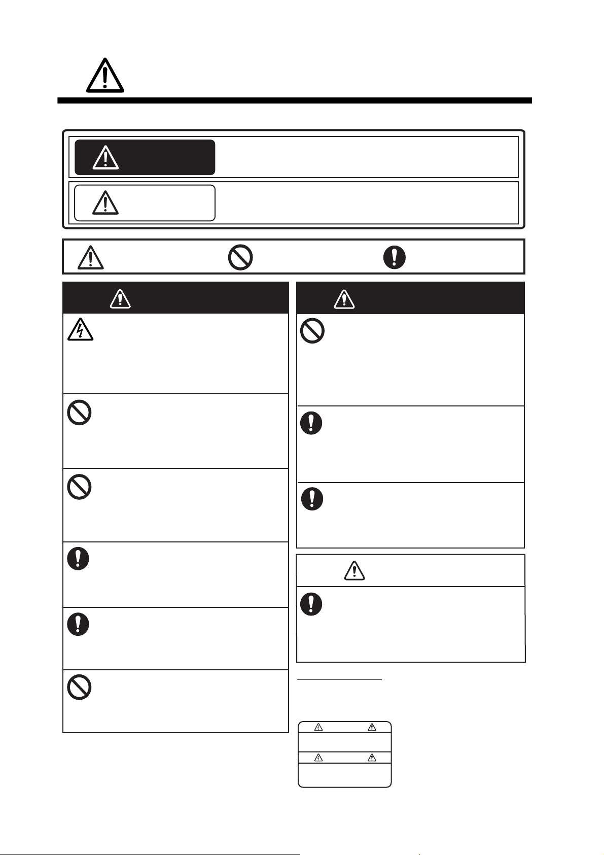
SAFETY INSTRUCTIONS
WARNING
WARNING
Please read these safety instructions before you operate the equipment.
Indicates a condition that can cause death or serious injury if
WARNING
CAUTION
not avoided.
Indicates a condition that can cause minor or moderate injury
if not avoided.
Warning, Caution
WARNING
Do not open the equipment unless
you are well familiar with electrical
circuits.
Only qualified personnel should work
inside the equipment.
Do not set the course changing
speed too high.
The boat will be turned too sharply at
the course change, which could create
a very dangerous situation.
Do not use the autopilot in the
following situations:
- Harbor entrance or narrow channel
- Where vessels change course often,
such as a cape or small island
Observe the following cautions when
using the autopilot:
- Maintain a vigilant watch
- Watch for drifting of vessel
In an emergency, manually steer the
vessel.
The autopilot cannot avoid vessels, etc.
automatically.
Do not use the SIMULATION mode on
the boat.
The rudder may move suddenly. This is
a special-purpose mode for technicians.
Prohibitive Action
Do not use the ORBIT mode in rough
seas.
Because the boat turns a 360° circle
around the waypoint, a large wave or
strong wind can cause the boat to
capsize.
For the figure-eight mode, confirm that
no object is in the general vicinity
of the waypoint.
The distance from the waypoint to the
turning point depends on boat's speed.
Use the correct fuse.
Use of a wrong fuse can cause fire or
damage the equipment.
In case of power failure, turn off the
autopilot or manually steer the vessel.
Leaving the equipment in the AUTO or
NAV mode during power failure will cause
wear on the rudder mechanism.
WARNING LABEL
A warning label is attached to the processor unit.
Do not remove the label. If the label is missing or
damaged, contact your dealer about replacement.
WARNING
To avoid electrical shock, do not
remove cover. No user-serviceable
parts inside.
Mandatory Action
WARNING
CAUTION
Name: Warning Label (1)
Type: 86-003-1011
Code No.: 100-236-231
ii
Page 5

TABLE OF CONTENTS
FOREWORD...................................................................................................................vi
SYSTEM CONFIGURATION .........................................................................................vii
1. INTRODUCTION ....................................................................................................1-1
1.1 Controls ......................................................................................................................1-1
1.1.1 Control Unit FAP-7001 ...................................................................................1-1
1.1.2 Control Unit FAP-7011 ...................................................................................1-2
1.1.3 Control Unit FAP-7021 ...................................................................................1-2
1.2 How to Turn Power On, Off ........................................................................................1-3
1.3 How to Adjust Brilliance, Contrast ..............................................................................1-4
1.3.1 NAVpilot-700 ..................................................................................................1-4
1.3.2 NAVpilot-711, NAVpilot-720 ...........................................................................1-4
1.4 Displays in the STBY, AUTO, NAV, WIND and FishHunter
1.4.1 Content of displays in the STBY, AUTO, NAV, WIND and
FishHunter
1.4.2 Graphic displays.............................................................................................1-9
1.4.3 How to select the data to show in the STBY mode ......................................1-12
1.4.4 How to select displays from the menu..........................................................1-13
TM
modes......................................................................................1-5
TM
Modes .......................1-5
2. STEERING MODES ...............................................................................................2-1
2.1 STBY Mode ................................................................................................................2-1
2.2 AUTO Modes..............................................................................................................2-2
2.2.1 AUTO mode ...................................................................................................2-2
2.2.2 ADVANCED AUTO mode ..............................................................................2-4
2.3 NAV Mode ..................................................................................................................2-5
2.3.1 How to get the NAV mode..............................................................................2-5
2.3.2 Sailing method for the NAV mode ..................................................................2-8
2.3.3 Waypoint switching method............................................................................2-9
2.3.4 How to set the steering behavior of your boat after you arrive to a waypoint.2-9
2.4 Response Feature....................................................................................................2-10
2.4.1 How to activate and set the response feature ..............................................2-10
2.4.2 How to deactivate the response feature.......................................................2-10
2.5 TURN Mode..............................................................................................................2-11
2.5.1 How to select a turn and start the turn .........................................................2-11
2.5.2 180° turn.......................................................................................................2-12
2.5.3 360° turn.......................................................................................................2-12
2.5.4 User turn.......................................................................................................2-12
2.6 FishHunter
2.6.1 How to preset FishHunter
2.6.2 How to select a FishHunter
2.6.3 Circle turn .....................................................................................................2-15
2.6.4 Orbit turn ......................................................................................................2-16
2.6.5 Spiral turn .....................................................................................................2-16
2.6.6 Figure-eight turn ...........................................................................................2-17
2.6.7 Square turn...................................................................................................2-17
2.6.8 Zigzag turn ...................................................................................................2-18
2.7 How to Navigate to a TLL Position ...........................................................................2-18
2.8 REMOTE Mode ........................................................................................................2-19
2.8.1 Dial-type remote controller (FAP-5551, FAP-5552) .....................................2-19
2.8.2 Button-type remote controller (FAP-6211, FAP-6212), Dodge-type remote
TM
Mode ..................................................................................................2-13
controller (FAP-6231, FAP-6232), Lever-type remote controller (FAP-6221,
FAP-6222) ....................................................................................................2-20
TM
turn parameters ..............................................2-13
TM
turn and start the turn...................................2-14
iii
Page 6

TABLE OF CONTENTS
2.9 DODGE Mode..........................................................................................................2-22
2.9.1 How to dodge in the AUTO and NAV modes...............................................2-22
2.9.2 How to FU dodge in the STBY mode...........................................................2-23
2.9.3 How to NFU dodge in the STBY mode ........................................................ 2-23
2.10 WIND Mode (for sailboats)....................................................................................... 2-23
2.10.1 How to get the WIND mode .........................................................................2-23
2.10.2 Wind angle mode ......................................................................................... 2-24
2.10.3 TACK mode..................................................................................................2-25
2.10.4 Tacking in WIND mode (WIND TACK).........................................................2-27
2.11 Safe Helm Mode ......................................................................................................2-31
2.12 Power Assist Mode ..................................................................................................2-33
3. ALARMS ................................................................................................................3-1
3.1 ALARM Menu............................................................................................................. 3-1
3.2 Alarm Buzzer..............................................................................................................3-2
3.3 Buzzer Interval ........................................................................................................... 3-2
3.4 Watch Alarm............................................................................................................... 3-3
3.5 Deviation Alarm.......................................................................................................... 3-3
3.6 XTE Alarm.................................................................................................................. 3-4
3.7 Arrival Alarm...............................................................................................................3-5
3.8 Speed Alarm ..............................................................................................................3-5
3.9 Depth Alarm ............................................................................................................... 3-6
3.10 Water Temperature Alarm..........................................................................................3-6
3.11 Trip Distance Alarm, Trip Distance Reset.................................................................. 3-7
3.11.1 How to set the log trip alarm .......................................................................... 3-7
3.11.2 How to reset the trip distance.........................................................................3-7
3.12 Wind Alarms (for sailboats)........................................................................................3-8
3.12.1 Heading change alarm...................................................................................3-8
3.12.2 Wind deviation alarm......................................................................................3-9
3.12.3 True wind speed alarm...................................................................................3-9
3.12.4 Apparent wind speed alarm ........................................................................... 3-9
3.13 Alarm Log................................................................................................................. 3-10
4. HOW TO CUSTOMIZE YOUR NAVPILOT ............................................................4-1
4.1 Parameter Setup (PARAMETER SETUP Menu) .......................................................4-1
4.1.1 Sea state........................................................................................................4-2
4.1.2 Trim gain ........................................................................................................ 4-5
4.1.3 Speed calculation........................................................................................... 4-6
4.2 Rudder Drive Level (For Fantum Feedback
4.3 Net Towing.................................................................................................................4-7
4.4 Course After Operation of a Remote Controller......................................................... 4-7
4.5 Nav Data Source........................................................................................................ 4-8
4.6 NavNet vx2 Synchronization......................................................................................4-8
4.7 SYSTEM SETUP Menu ............................................................................................. 4-9
4.8 Menu Shortcuts........................................................................................................4-11
4.8.1 How to create a menu shortcut .................................................................... 4-11
4.8.2 How to delete a menu shortcut ....................................................................4-11
TM
).......................................................... 4-6
5. MAINTENANCE, TROUBLESHOOTING...............................................................5-1
5.1 Preventive Maintenance.............................................................................................5-1
5.2 Replacement of Fuse ................................................................................................. 5-2
5.3 Diagnostics.................................................................................................................5-2
5.3.1 Diagnostic menu ............................................................................................5-2
5.3.2 Processor unit test .........................................................................................5-3
5.3.3 Control unit test..............................................................................................5-3
5.3.4 NMEA0183 test..............................................................................................5-4
iv
Page 7

TABLE OF CONTENTS
5.3.5 CAN bus test ..................................................................................................5-4
5.3.6 Keyboard test .................................................................................................5-5
5.3.7 Screen test .....................................................................................................5-5
5.3.8 Rudder test.....................................................................................................5-6
5.3.9 Helm sensor test ............................................................................................5-8
5.4 System Data...............................................................................................................5-8
5.5 Messages ...................................................................................................................5-9
5.5.1 Message pop-up display ................................................................................5-9
5.5.2 Message board...............................................................................................5-9
5.5.3 Message description ......................................................................................5-9
5.6 Sensor in Use Display ..............................................................................................5-12
APPENDIX 1 MENU TREE .......................................................................................AP-1
SPECIFICATIONS .....................................................................................................SP-1
INDEX ......................................................................................................................... IN-1
v
Page 8

FOREWORD
A Word to the Owner of the NAVpilot-700/711/720
Congratulations on your choice of the NAVpilot-700/711/720. We are confident you will see why
the FURUNO name has become synonymous with quality and reliability.
Since 1948, FURUNO Electric Company has enjoyed an enviable reputation for innovative and
dependable marine electronics equipment. This dedication to excellence is furthered by our extensive global network of agents and dealers.
Your equipment is designed and constructed to meet the rigorous demands of the marine environment. However, no machine can perform its intended function unless properly operated and
maintained. Please carefully read and follow the operation and maintenance procedures set forth
in this manual.
Thank you for considering and purchasing FURUNO.
We would appreciate feedback from you, the end-user, about whether we are achieving our purposes.
Features
• “Adaptive” technology allows NAVpilot to continue improving your vessel’s steering on every
voyage
• Versatile, high-resolution monochrome LCDs provide a variety of user-defined display configurations
• Auto set-up and self-learning for vessel speed and course
• One-touch operation for STBY, NAV and AUTO modes
• “FishHunter
ver around fish or other target
• The NAVpilot-720 (handheld type) can work as a full-functioned remote control unit within a
NAVpilot system
• Network up to six full-size NAVpilot-700, compact NAVpilot-711 and/or handheld NAVpilot-720
control units
TM
” guides your vessel in circle, orbit, spiral, figure-eight, square or zigzag maneu-
vi
Page 9
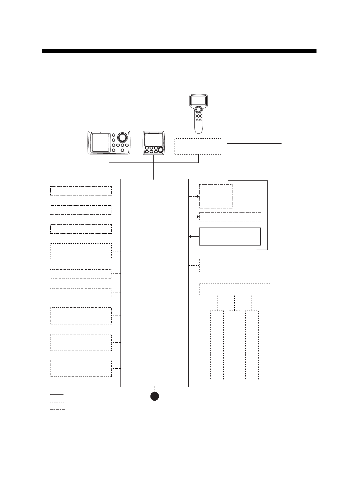
SYSTEM CONFIGURATION
NAVpilot-700/711/720 can be controlled with the rudder reference unit or without it (Fantum Feed-
TM
back
). For details of Fantum FeedbackTM, see the installation manual (IME-72720-x).
CONTROL UNIT
CONTROL UNIT
FAP-7001
CONTROL UNIT
FAP-7011
FAP-7021
CONTACT SIGNAL IN
CONTACT SIGNAL OUT
PC (for serviceman)
HEADING SENSOR
PG-700
EXTERNAL BUZZER
EVENT SWITCH
NAV EQUIPMENT
(NMEA 0183)
Select one
PROCESSOR UNIT
FAP-7002
JUNCTION BOX
FAP-7822
SOLENOID
VALVE
HYDRAULIC LINEAR DRIVE
RUDDER REFERENCE UNIT
REMOTE CONTROLLER
DISTRIBUTOR FAP-6800
CONTROL UNIT QTY
FAP-7001/7011: MAX. 6*
FAP-7021: MAX. 2
2
FAP-6112
*
1
SHIP'S
STEERING
SYSTEM
NAV EQUIPMENT
(NMEA 0183)
CANBUS EQUIPMENT
(NMEA 2000)
: STANDARD
: OPTION
: USER SUPPLY
*1 : Any combination of FAP-7001 and
FAP-7011 is available. Also, FAP-7021
can be connected at the end of series.
2
: RRU is not required for Fantum FeedbackTM.
*
12-24 VDC
REMOTE CONTROLLER
REMOTE CONTROLLER
REMOTE CONTROLLER:
DIAL TYPE: FAP-5551, FAP-5552
BUTTON TYPE: FAP-6211, FAP-6212
LEVER TYPE: FAP-6221, FAP-6222
DODGE TYPE: FAP-6231, FAP-6232
REMOTE CONTROLLER
vii
Page 10

SYSTEM CONFIGURATION
This page is intentionally left blank.
viii
Page 11

1. INTRODUCTION
1.1 Controls
The Control Unit for your NAVpilot is either the FAP-7001, FAP-7011, or FAP-7021.
The descriptions in this manual mainly follow the key names of the NAVpilot-700 (Control Unit FAP-7001). Refer to the table below for equivalent controls on the NAVpilot711 and NAVpilot-720.
1.1.1 Control Unit FAP-7001
STBY key
- Select STBY (manual) mode.
- Press together with AUTO to
get WIND mode (sailboats only).
NAV key
Select
NAV mode.
AUTO key
Selects AUTO mode.
MENU key
Open/close menu.
PORT key
Steer boat to port.
Course control knob
Rotate: Select menu items and
options; set course on AUTO mode.
Push: Confirm menu setting.
STBD (STARBOARD) key
Steer boat to starboard.
POWER/BRILL key
Momentary press: Turn on power,
adjust contrast and brilliance.
TURN key
Open TURN menu.
Long press: Turn off power.
1-1
Page 12

1. INTRODUCTION
1.1.2 Control Unit FAP-7011
PORT key
Steer boat to port.
POWER/STBY key
Momentary press: Turn on
power; go to STBY mode.
Long press: Turn off power.
WIND mode: Press together
with AUTO to get WIND mode
(sailboats only).
AUTO key
Select AUTO mode.
STBD (STARBOARD) key
Steer boat to starboard.
Course control knob
Rotate: Select menu items and
options; set course on AUTO mode.
Push: Confirm menu setting.
NAV key
Select NAV mode.
TURN/MENU key
Momentary press: Open TURN menu.
Long press: Open/close menu.
1.1.3 Control Unit FAP-7021
Course control knob
Rotate: Select menu items and
options; set course on AUTO mode.
Push: Confirm menu setting.
PORT key
Steer boat to port.
STBY/POWER key
Momentary press: Turn power
on; select STBY (manual) mode.
Long press: Turn power off.
WIND mode: Press together with
AUTO to get WIND mode (sailboats
only.)
TURN/MENU key
Momentary press: Open TURN menu.
Long press: Open/close menu.
STBD (STARBOARD) key
Steer boat to starboard.
WIND
AUTO key
Select AUTO mode.
NAV key
Select NAV mode.
1-2
Page 13
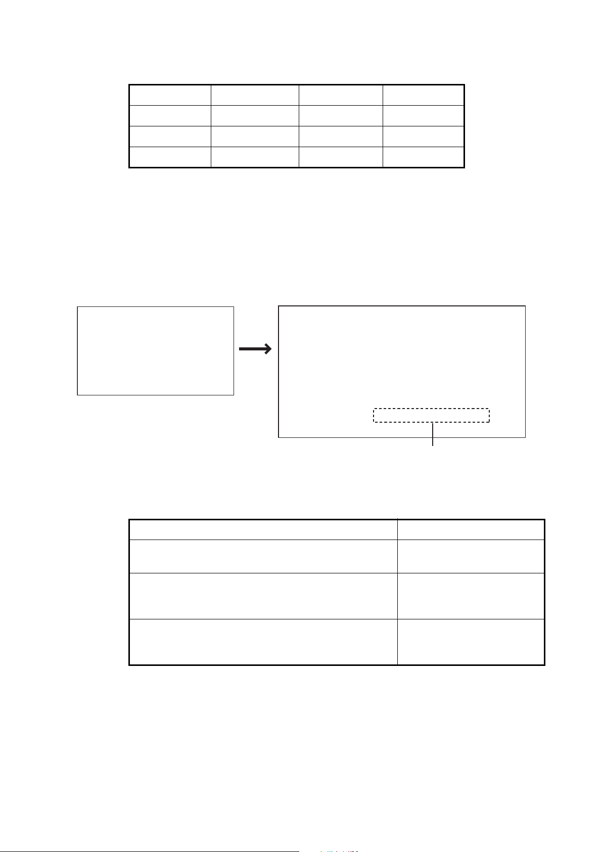
1.2 How to Turn Power On, Off
Control unit Key ON OFF
FAP-7001 POWER/BRILL Short-press Long-press*
FAP-7011 POWER/STBY Short-press Long-press*
FAP-7021 STBY/POWER Short-press Long-press*
*:A timer counts down the time that remains until the power goes off
When the heading sensor PG-500 (or PG-700) is connected, see the note at the bottom of this page. A beep sounds and the equipment shows product information followed by the results of the startup test. The start up test checks the ROM, RAM and
backup of the processor unit and control unit. The test also checks for the presence of
heading from the heading sensor and rudder angle information from the rudder reference unit.
START UP TEST
AUTO PILOT
NAVPILOT-700*
FURUNO ELECTRIC CO., LTD
* Or NAVPILOT-711, NAVPILOT-720
PROCESSOR 6454007-**.**
CONTROLLER 6454011-**.**
ROM RAM BACKUP
PROCESSOR UNIT OK OK OK
CONTROLLER OK OK OK
HEADING SENSOR OK 359.9°
------------------------------------------RRU OK xx.x°
CONTROLLER ID 1
1. INTRODUCTION
**.** : Program version no.
For Fantum FeedbackTM, “FANTUM FEEDBACK” is displayed.
If NG appears for any item, an error message, shown in the table below, appears. Follow the information provided in the message to restore normal operation. If you cannot
restore normal operation, contact your dealer for information.
Error message Meaning
BACK UP DATA IS BROKEN. USE FACTORY DEFAULT. PUSH ANY KEY TO CONTINUE.
CAN NOT RECEIVE HEADING DATA. PLEASE
CHECK THE HEADING SENSOR. PUSH ANY KEY TO
CONTINUE.
SYSTEM HAS FAILED STARTUP TEST. PLEASE
CONTACT LOCAL FURUNO REPRESENTATIVE FOR
REPAIR. PUSH ENTER KNOB TO CONTINUE.
Note: When the Heading Sensor PG-500/PG-700 is connected, turn on the NAVpilot
and wait four minutes before you leave port. This allows time for the PG-500/PG-700
heading data to stabilize.
Backup data is corrupted.
Problem with heading sensor.
The system has failed the
startup test.
1-3
Page 14
1. INTRODUCTION
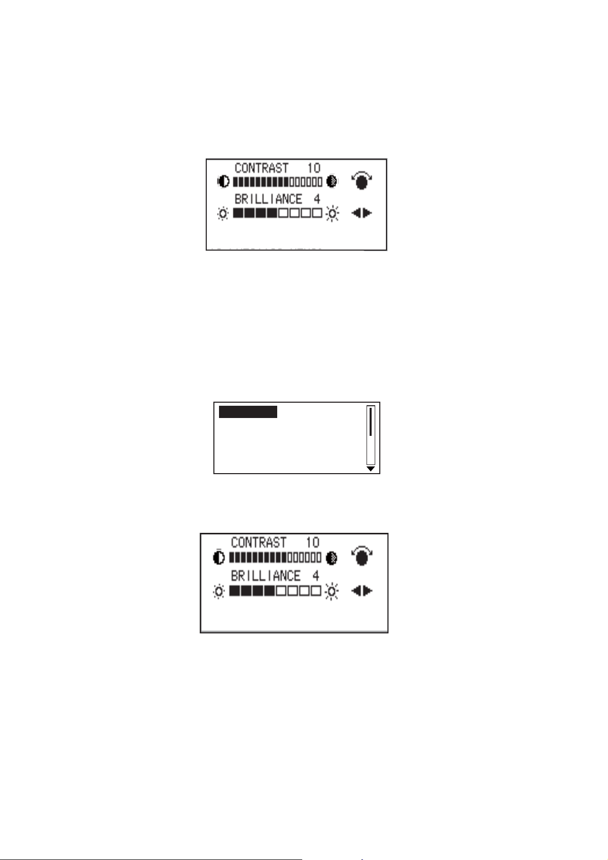
1.3 How to Adjust Brilliance, Contrast
1.3.1 NAVpilot-700
1. Short-push the POWER/BRILL key to show the screen for the adjustment of contrast and brilliance.
2. Operate the Course control knob to adjust the contrast. (Contrast can also be adjusted (cyclically) with the POWER/BRILL key.)
3. Operate the W or X key to adjust the brilliance.
4. Push the Course control knob to close the screen, or wait several seconds for
the screen to close automatically.
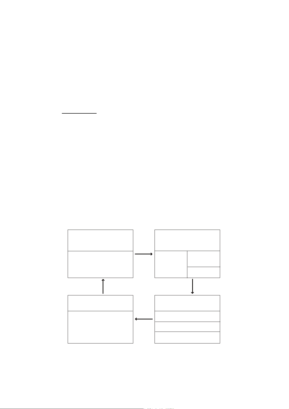
1.3.2 NAVpilot-711, NAVpilot-720
1. Long-push the TURN/MENU key to open the menu.
MESSAGE
SENSOR IN USE
CONTRAST/BRILLIANCE
RUDDER DRIVE LEVEL*
SEA STATE: FULL-AUTO
*: Shown with Fantum FeedbackTM.
2. Rotate the Course control knob to select [CONTRAST/BRILLIANCE] then push
the knob. The screen for the adjustment of contrast and brilliance appears.
PUSH MENU KEY TO RETURN
TO PREVIOUS MENU.
3. Operate the Course control knob to adjust the contrast.
1-4
4. Operate the W or X key to adjust the brilliance.
5. Push the Course control knob to close the screen, or wait several seconds for
the screen to close automatically.
Page 15
1. INTRODUCTION
1.4 Displays in the STBY, AUTO, NAV, WIND and
TM
FishHunter
There are four (NAVpilot-700) or five (NAVpilot-711, NAVpilot-720) displays to select
from in the STBY mode. For Fantum Feedback
711, NAVpilot-720) to select. To select a display, press the STBY key, AUTO key or
NAV key continuously to step through the displays.
1.4.1 Content of displays in the STBY, AUTO, NAV, WIND and Fish-
TM
Hunter
NAVpilot-700
• Autopilot Display 1 (Digital course and heading, and rudder angle or heading deviation)
• Autopilot Display 2 (Digital course and heading, rudder angle or heading deviation,
and one or two nav data displays)
• Nav Data Display (Digital course and heading, and two or three digital nav displays)
modes
Modes
TM
, there are three display (NAVpilot-
• Graphic Display (Digital course and heading, and graphic display)
• Press the STBY key to show the displays in the STBY mode.
Note 1: For the WIND mode, the wind deviation replaces the heading deviation.
Note 2: The rudder angle can not be selected in case of Fantum Feedback
TM
.
Note 3: The number of boxes depends on setting of DATA BOX FORMAT in the DISPLAY SETUP menu in the INSTALLATION menu.
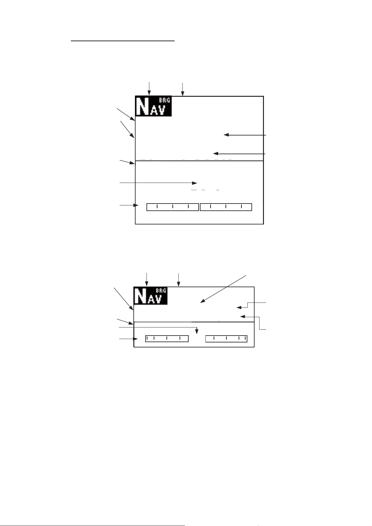
Autopilot
Display 1
MODE
COURSE
HEADING
Rudder angle
or
heading deviation
[1] (page no.)
Graphic
display
3
*
STBY, AUTO*
or NAV*2 key
MODE
COURSE HEADING
GRAPHIC display
STBY,
AUTO
or
NAV
key
4
*
1
STBY,
AUTO
or
NAV
key
Autopilot
Display 2
MODE
1
*
COURSE
2
*
HEADING
Rudder angle
or
heading
deviation
[2] (page no.)
3
*
Nav data
display
MODE
1
*
COURSE HEADING
2
*
NAV DATA
NAV DATA
4
*
NAV DATA
STBY, AUTO*
or NAV*2 key
1
NAV DATA
NAV DATA
[4] (page no.)
1
AUTO or WIND mode
*
2
NAV or FishHunterTM mode
*
3
Page no. appears when selecting display.
*
4
See Note1 and Note2 as above.
*
3
*
[3] (page no.)
Displays (NAVpilot-700)
3
*
1-5
Page 16
1. INTRODUCTION
NAVpilot-711, NAVpilot-720
When the rudder reference unit is installed
• Autopilot Display 1 (Digital course and heading)
• Autopilot Display 2 (Digital course and heading, and rudder angle or heading deviation)
• Nav Data Display 1 (Digital course and heading, rudder angle or heading deviation,
and one nav data display)
• Nav Data Display 2 (Digital course and heading, and one or two digital nav data display)
• Graphic Display (Digital course and heading, and graphic display)
• Press the STBY key to show the displays in the STBY mode.
Note 1: For the WIND mode, the wind deviation replaces the heading deviation.
Autopilot
Display 1
MODE
COURSE
HEADING
[1] (page no.)
Note 2: The rudder angle can not be selected in case of Fantum Feedback
TM
.
Note 3: The number of boxes depends on setting of DATA BOX FORMAT in the DISPLAY SETUP menu in the INSTALLATION menu.
3
*
Graphic
Display
MODE
GRAPHIC display
Autopilot
Display 2
STBY,
AUTO
or
NAV
key
MODE
1
*
COURSE HEADING
2
*
Rudder angle
heading deviation
[2] (page no.)
STBY, AUTO*
or NAV*2 key
1
COURSE HEADING
or
3
*
STBY,
AUTO
or
NAV
key
STBY,
AUTO
or
NAV
key
4
*
Nav Data
Display 2
MODE
1
*
COURSE HEADING
2
*
NAV DATA
Nav Data
Display 1
MODE
1
*
COURSE HEADING
2
*
Rudder angle
or
heading
deviation
[3] (page no.)
STBY, AUTO*
or NAV*2 key
4
*
3
*
NAV DATA
NAV DATA
1
1-6
[5] (page no.)
1
AUTO or WIND mode
*
2
NAV or FishHunterTM mode
*
3
Page no. appears when selecting display.
*
4
See Note 1 and Note 2 as above.
*
3
*
[4] (page no.)
3
*
Displays when the RRU is installed (NAVpilot-711, 720)
Page 17
1. INTRODUCTION
For Fantum Feedback
TM
• Autopilot Display 1 (Digital course and heading)
• Nav Data Display 2 (Digital course and heading, and one or two digital nav data display)
• Graphic Display (Digital course and heading, and graphic display)
• Press the STBY key to show the displays in the STBY mode.
Note: The number of boxes depends on setting of DATA BOX FORMAT in the DISPLAY SETUP menu in the INSTALLATION menu.
Autopilot
Display 1
MODE
COURSE
HEADING
3
*
1
STBY,
AUTO
or
NAV
key
Nav Data
Display 2
MODE
1
*
COURSE HEADING
2
*
STBY, AUTO*
or NAV*2 key
1
Graphic
Display
MODE
COURSE HEADING
GRAPHIC display
[1] (page no.)
STBY, AUTO*
or NAV*2 key
NAV DATA
[3] (page no.)
1
*
AUTO or WIND mode
2
NAV or FishHunter mode
*
3
Page no. appears when selecting display.
*
3
*
[2] (page no.)
NAV DATA
3
*
1-7
Page 18

1. INTRODUCTION
Available displays
The table below shows all the nav data and graphic displays available. Appropriate
sensors are required.
Data displayed Data meaning
Nav data displays
AIR TEMP Air temperature
ATMOS PRESS Atmospheric pressure
BRG Bearing to waypoint
COG Course over ground
DATE Current date
DEWPOINT Dewpoint
DPT Depth
ETA Estimated time of arrival to waypoint
HUMIDITY Humidity
POS Position
RNG Range to waypoint
SOG Speed over ground
STW Speed through water
TEMP Water temperature
TIME Current time
TRIP Trip distance
TTG Time-to-go to waypoint
VOLT Input/output voltage to processor unit
WIND APPARENT Apparent wind direction/speed
WIND TRUE True wind direction/speed
WPT Waypoint position (Latitude/Longitude)
XTE Cross-track error
Graphic displays
1
COMPASS, RUDDER*
Compass rose, and analog and digital rudder angle
DEPTH Analog and digital depth
ENGINE SPEED Analog engine speed (revolution meter)
HIGHWAY Graphic presentation of progress towards waypoint
RUDDER*
1
Analog and digital rudder angle
TEMP Analog (graph) and digital water temperature
WIND APPARENT Analog and digital apparent wind direction speed
WIND TRUE Analog and digital true wind direction speed
Rudder angle, deviation, wind deviation (analog)
RUDDER*
1
DEVIATION*
WIND DEV.*
*
*
For Fantum Feedback
2
3
1
Can not be selected in case of Fantum FeedbackTM.
2
Any mode other than WIND.
Rudder angle
Heading deviation:
Wind deviation
TM
, NAVpilot-711 and NAVpilot-720 can not display
[DEVIATION].
3
*
WIND mode only
1-8
Page 19
1.4.2 Graphic displays
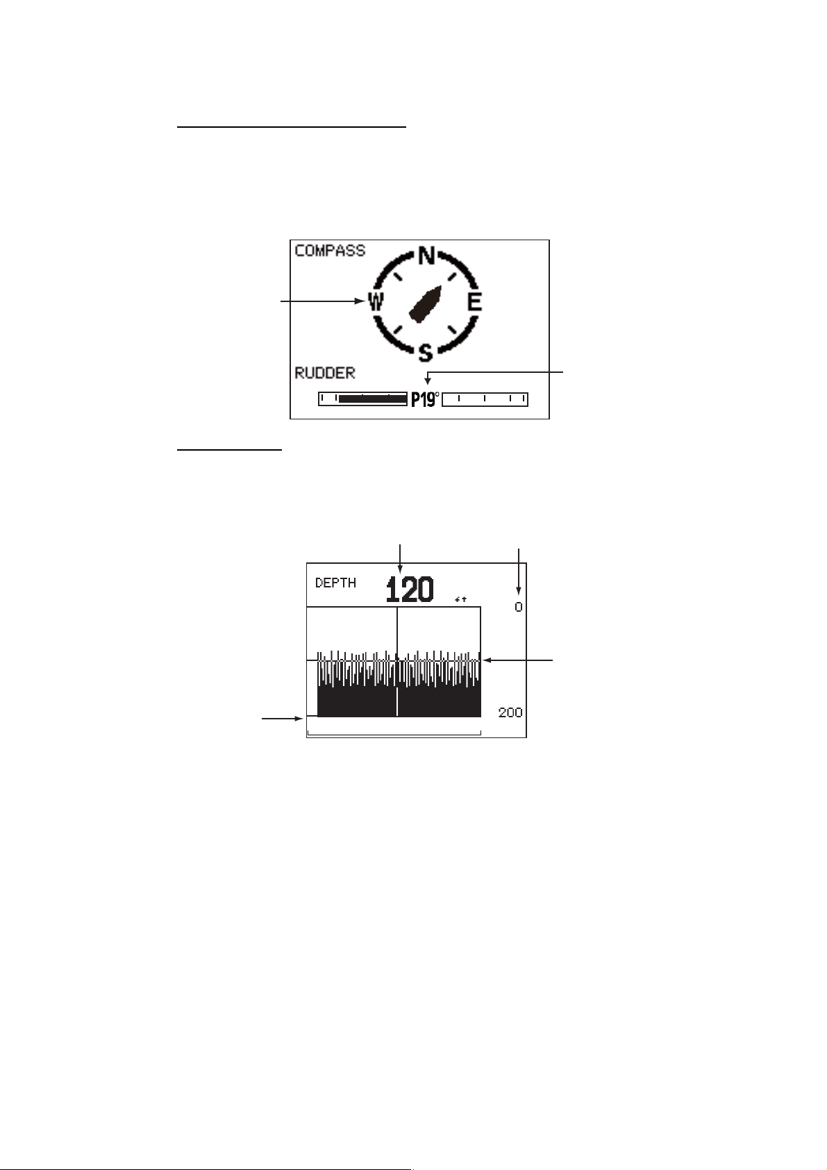
Compass rose, rudder display
The compass rose and rudder display show ship’s heading in graphic form and rudder
angle in both analog and digital formats. Requires heading data.
1. INTRODUCTION
Note: Not available with Fantum Feedback
Compass
rose
20 10 5 5 10 20
TM
.
Rudder
angle
°
(port 19
)
Depth display
The depth display provides depth data in a graph. Data scrolls across the screen from
right to left. Requires depth data.
Current Depth
Depth scale
Interval
(selected on
menu)
Latest data
at right edge
01
1-9
Page 20
1. INTRODUCTION
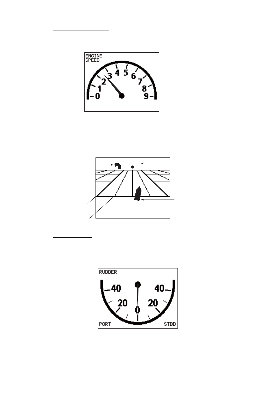
Engine speed display
The engine speed display shows the engine revolution. Requires engine speed data.
Highway display
The highway display provides a graphic presentation of your boat’s progress along its
intended course. The own ship marker moves according to your boat’s track to the
waypoint.
9: 9000 rpm
Direction to
next waypoint
0.1
0.05
001WP
Waypoint name
Own ship marker
Rudder display
Note: Not available with Fantum FeedbackTM.
The rudder display shows analog and digital rudder angle.
O°
1-10
Page 21
1. INTRODUCTION
r
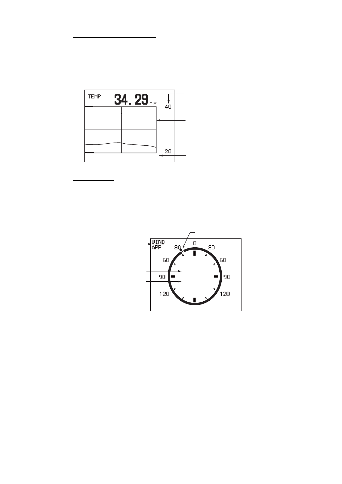
Water temperature display
The water temperature display shows water temperature over the selected time interval, and the current water temperature. Data scrolls across the screen from right to
left. The interval of time can be selected from the menu. Requires water temperature
data.
Temperature
scale
Latest data
at right edge
10
0
Interval (selected on menu)
Wind display
The wind display shows wind angle and wind speed. The data can be shown in true
wind or apparent wind. The apparent wind is the actual flow of air acting upon a sail,
or the wind as it appears to the sailor. The true wind is the wind seen by a stationary
observer in velocity and direction. Requires a wind sensor.
Wind angle marke
Wind mode
(TRUE or APP)
Wind angle
Wind speed
30.1°
10.2
kn
1-11
Page 22
1. INTRODUCTION
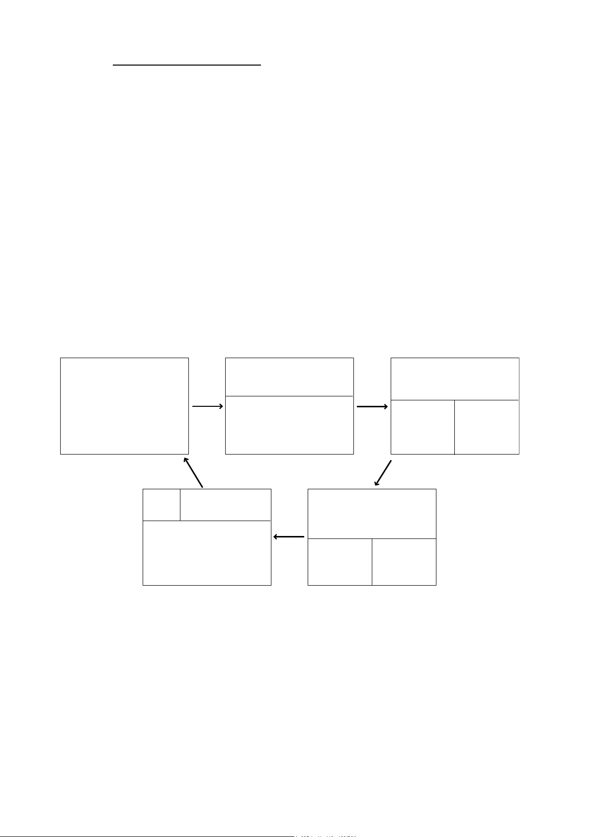
1.4.3 How to select the data to show in the STBY mode
You can select the data to show in the STBY mode as follows:
1. Short press the STBY key to go to the STBY mode.
2. Press the STBY key again to select a display. For example, select the nav data
display.
MODE
COURSE HEADING
NAV DATA NAV DATA
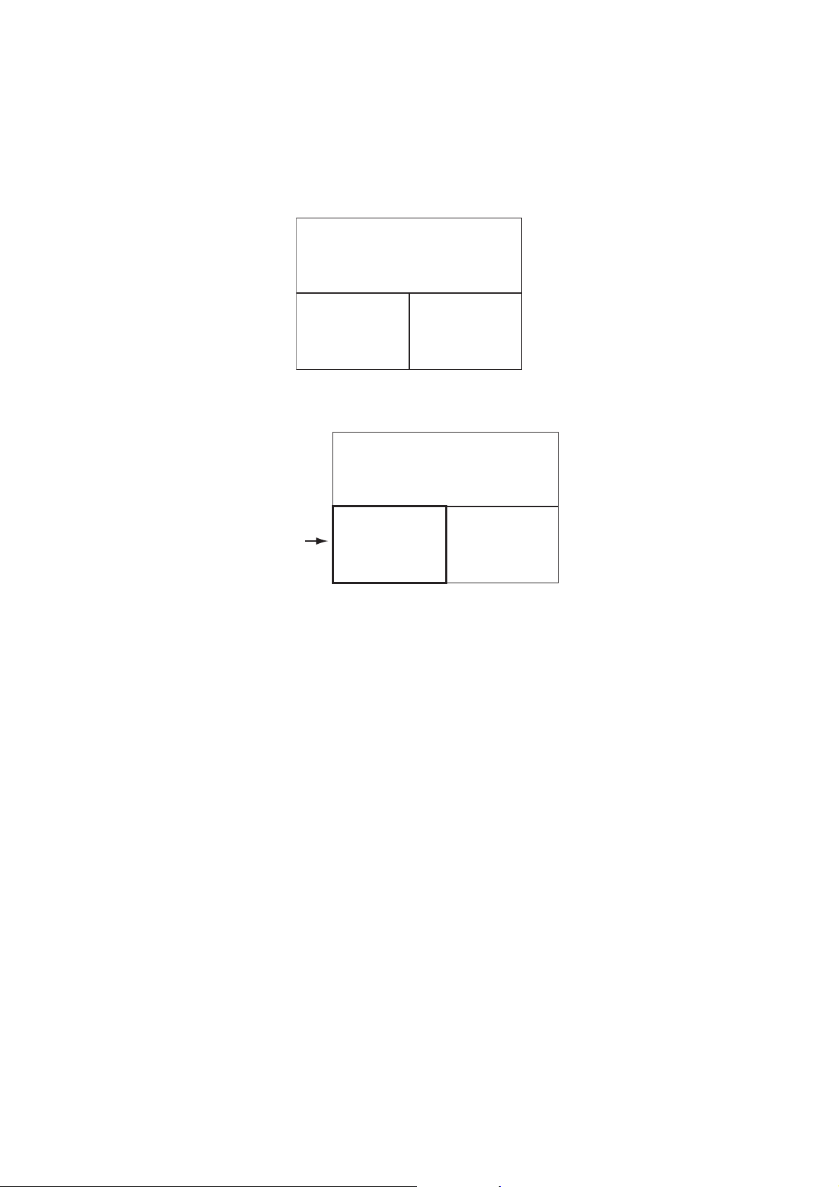
3. Push the Course control knob. The item selected by the cursor is circumscribed
with a thick rectangle, as in the illustration below.
MODE
COURSE HEADING
NAV DATA NAV DATA
Cursor
4. For multi-data display, press W or X to put the cursor on the data to change.
5. Rotate the Course control knob to select the data (or graphic) (Graphic displays:
Depth graph, Temperature graph, Engine speed, Compass rose, Rudder, Highway, Wind)
6. Push the Course control knob.
1-12
Page 23
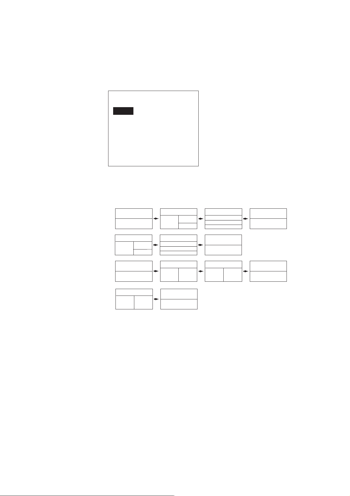
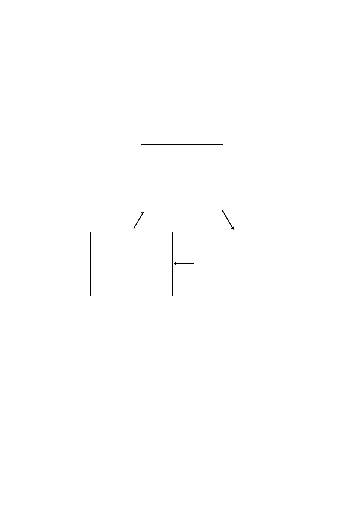
1.4.4 How to select displays from the menu
You can select the nav data or graphic display to show in the STBY, AUTO(WIND)
and NAV(FishHunter
1. Open the [SYSTEM SETUP] menu, select [DISPLAY DATA SELECT MENU] then
push the Course control knob.
DISPLAY DATA SELECT MENU
STBY
AUTO
NAV
WIND*
* Visible when [SHIP’S CHARACTERISTICS]=sailboat
2. Rotate the Course control knob to select the mode desired then push the knob.
Rotate the knob to select the display division desired then push the knob. The example below shows the display divisions in the STBY, AUTO and NAV modes.
TM
) modes.
1. INTRODUCTION
NAVpilot-700
(When the RRU is installed)
NAVpilot-700
TM
(For Fantum Feedback
)
NAVpilot-711, 720
(When the RRU is installed)
NAVpilot-711, 720
(For Fantum Feedback
TM
STBY, AUTO, NAV[1]*
1
STBY, AUTO, NAV[2]*
STBY, AUTO, NAV[2]*
1
STBY, AUTO, NAV[2]*
)
1 2
STBY, AUTO, NAV[2]*
1
2
3
STBY, AUTO, NAV[3]*
1
2
1
2
3
STBY, AUTO, NAV[3]*
1 2
STBY, AUTO, NAV[3]*
1
STBY, AUTO, NAV[3]*
1
2
3
STBY, AUTO, NAV[4]*
1
STBY, AUTO, NAV[4]*
1 2
STBY, AUTO, NAV[4]*
1
STBY, AUTO, NAV[5]*
1
* “WIND” available when [SHIP’S CHARACTERISTICS]=sailboat
Note: The number of boxes depends on setting of DATA BOX FORMAT in the
DISPLAY SETUP menu in the INSTALLATION menu.
1-13
Page 24

1. INTRODUCTION
3. Rotate the Course control knob to select “1:” or “2:”, “3:” then push the knob. The
choices available for each division are as follows:
NAVpilot-700 (When the RRU is installed): 1 of [1], [2]
NAVpilot-711, 720 (When the RRU is installed): 1 of [2], [3]
RUDDER
DEVIATION
Note: For Fantum Feedback
TM
, the display as above is not showned.
NAVpilot-700 (When the RRU is installed): 2 and 3 of [2], 1, 2 and 3 of [3]
NAVpilot-700 (For Fantum Feedback
TM
): 1 and 2 of [2], 1, 2 and 3 of [3]
NAVpilot-711, 720 (When the RRU is installed): 2 of [3], 1 and 2 of [4]
TM
NAVpilot-711, 720 (For Fantum Feedback
POS
COG
SOG
STW
TEMP
DPT
BRG
RNG
WPT
Page 1
XTE
TTG
ETA
DATE
TIME
WIND TRUE*
1
WIND APPARENT*
VOLT
TRIP
Page 2
): 1 and 2 of [2]
AIR TEMP
ATMOS PRESS
HUMIDITY
DEW POINT
Page 3
1
NAVpilot-700: 1 of [4]
NAVpilot-711, 720 (When the RRU is installed): 1 of [5]
NAVpilot-711, 720 (For Fantum Feedback
COMPASS
RUDDER
*2
2
*
TM
): 1 of [3]
HIGHWAY
1
WIND TRUE
WIND APPARENT
DEPTH
*
*1 Shown when [SHIP’S CHARACTERISTICS]=sailboat
1
*
*2 Not shown in case of Fantum FeedbackTM.
TEMP
ENGINE SPEED
Graphic display
4. Rotate the Course control knob to select nav data desired then push the knob.
5. Set other patterns similarly.
6. Press the MENU key four times to close the menu.
1-14
Page 25
2. STEERING MODES
Your NAVpilot has eight primary steering modes: STBY (manual), AUTO, NAV,
TM
TURN, FishHunter
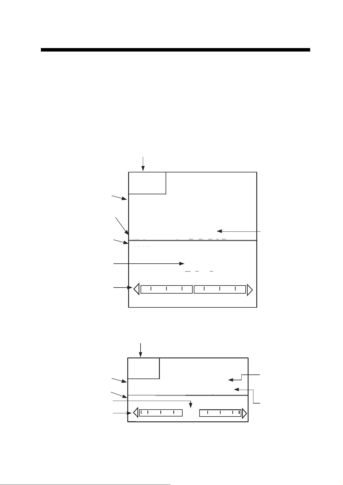
2.1 STBY Mode
After turning on the power, the equipment goes to the STBY mode. This is a manual
steering mode. When sailing into or out of a harbor, steer the vessel in the STBY mode
by using the steering wheel (helm) of your boat.
Course mode
Heading mode
T: True
M: Magnetic
Data name (rudder)
, DODGE, REMOTE (FU and NFU), and WIND (for sailboats).
Steering mode
S
TBY
SETCSE
ー
HDG
T
RUDDER
323°
°
Heading
Rudder angle (digital)
Rudder angle (analog)
Course mode
Data name (rudder)
Rudder angle (digital)
Rudder angle (analog)
20 10 5 5 10 20
Autopilot display 1 (NAVpilot-700)
Steering mode
S
TBY
SETCSE
RUDDER
20 10 5 5 10 20
0°
°
ー
0°
HDG T
323°
Heading mode
T: True
M: Magnetic
Heading
Autopilot display 2 (NAVpilot-711, NAVpilot-720)
2-1
Page 26
2. STEERING MODES
2.2 AUTO Modes
2.2.1 AUTO mode
The AUTO mode steers the boat automatically on a course set by the operator.
The AUTO mode will not compensate for the effects of wind or tide, which can push
you off course athwart in the ship direction. Use the AUTO mode for short, straight
voyages. Otherwise switch to the NAV mode.
Tide and WindTide and Wind Tide and Wind
To get the AUTO mode, do as follows:
1. Direct the boat toward required course.
2. Press the AUTO key to activate the AUTO mode.
Your boat automatically maintains the current course when the AUTO key is
pressed.
When the heading changes from the set course, the NAVpilot automatically adjusts the rudder to return the boat to the set course.
3. To change the course setting in the AUTO mode, rotate the Course control knob
to the required course.
2-2
Page 27
2. STEERING MODES
4. To exit the AUTO mode to steer manually, press the STBY key. Steer your boat
by the helm.
Course mode
Heading mode
T: True
M: Magnetic
Data name (rudder)
Rudder angle (digital)
Rudder angle (analog)
Steering mode: AUTO
SETCSE
323°
HDG
T
RUDDER
20 10 5 5 10 20
Autopilot display 1 (NAVpilot-700)
Steering mode: AUTO
323°
0°
Set course
Heading
Course mode
Data name (rudder)
Rudder angle (digital)
Rudder angle (analog)
Set course
SETCSE
323°
RUDDER
20 10 5 5 10 20
Autopilot display 2 (NAVpilot-711, NAVpilot-720)
0°
HDG T
323°
Heading mode
T: True
M: Magnetic
Heading
2-3
Page 28
2. STEERING MODES
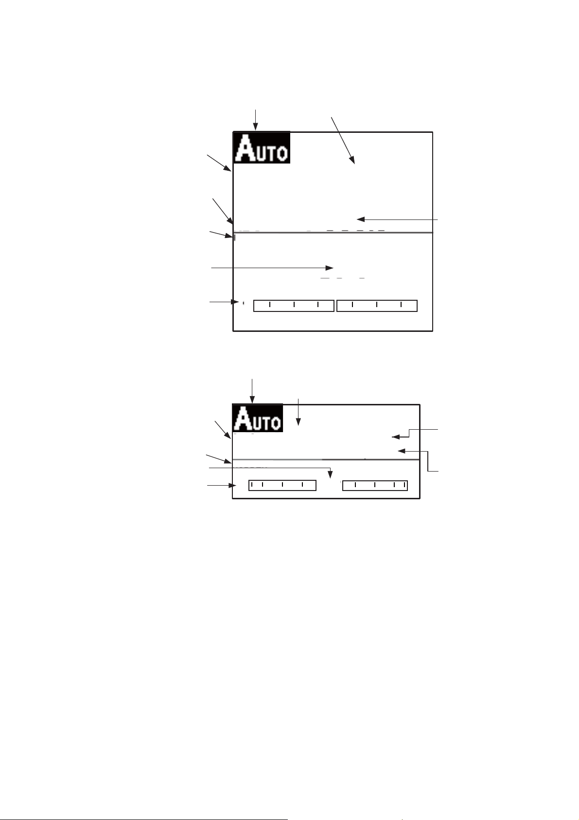
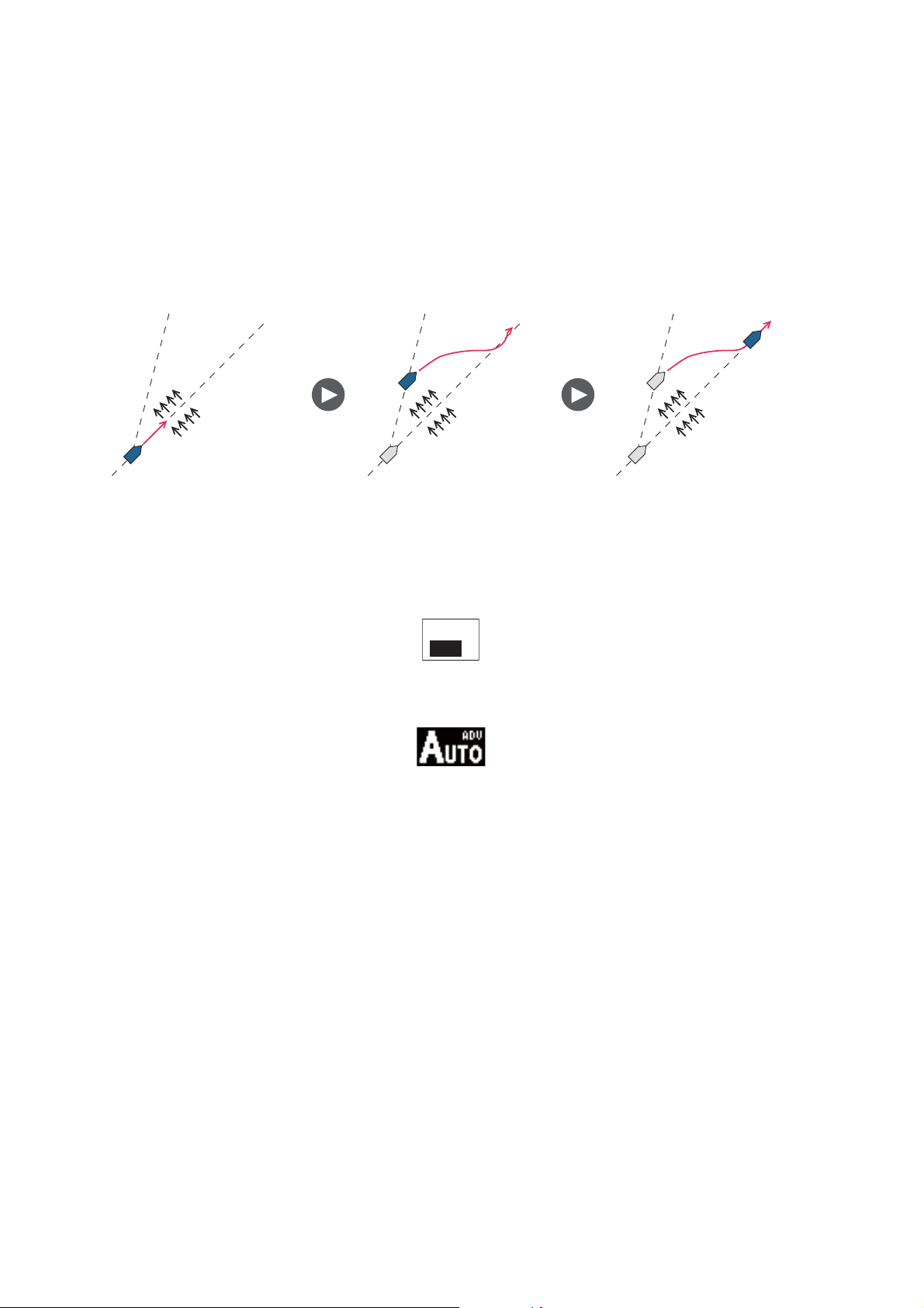
2.2.2 ADVANCED AUTO mode
The AUTO mode keeps a set course, but your boat’s course can change by the effects
of tide and wind. To adjust for the effects of tide and wind, use the ADVANCED AUTO
mode. The NAVpilot calculates your course according to your current position and
heading, then sets a virtual "waypoint" in its memory to navigate towards. If either tide
or wind begins to push you off course, the NAVpilot corrects your heading accordingly.
Your NAVpilot must be connected to a GPS navigator which outputs position data
(Latitude and Longitude).
Tide and Wind Tide and WindTide and Wind
To get the ADVANCED AUTO mode, do as follows:
1. In the AUTO mode, press the MENU key to show the menu.
2. Rotate the Course control knob to select [ADVANCED AUTO] then push the
Course control knob to show the advanced auto options window.
OFF
ON
3. Rotate the Course control knob to select [ON]. The steering mode display changes as below.
Select [OFF] to quit the ADVANCED AUTO mode.
4. Push the Course control knob to confirm the setting.
5. Press the MENU key to close the menu.
You can switch between AUTO and ADVANCED AUTO modes by holding down the
AUTO key three seconds to show the message "ADVANCED AUTO ON (OFF)" appears.
Note: How strictly the ADVANCED AUTO mode keeps the course depends on the
NAV MODE setting in the NAV OPTION menu. COURSE/XTE(ECONOMY) keeps the
course within 0.03 NM and XTE(PRECISION) keeps the course within 0.01 NM.
2-4
Page 29
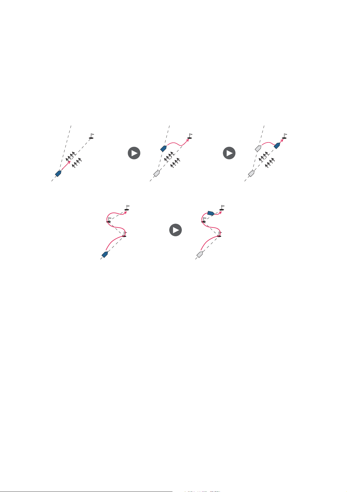
2.3 NAV Mode
NAVpilot steers the vessel towards the current waypoint while compensating for the
effects of tide and wind.
When connected to a GPS Navigator, NAVpilot steers the vessel to follow a series of
waypoints in sequence. When you arrive at each waypoint or destination, audible and
visual alerts are activated.
The NAVpilot takes 15 seconds to activate the NAV mode after the NAVpilot receives
the destination information.
2. STEERING MODES
Waypoint
Tide and Wind
Steering to a single waypoint
Waypoint Waypoint
Steering a route (a series of waypoints)
Tide and Wind
2.3.1 How to get the NAV mode
Waypoint
Waypoint
Tide and Wind
To get the NAV mode, do as follows:
1. Set the destination waypoint (or route) on the GPS navigator or chartplotter.
(To navigate a route, make sure that your plotter is navigating towards the nearest
or required waypoint before you put the NAVpilot into the NAV mode.)
2. Manually steer the boat toward the waypoint.
3. Press the NAV key.
4. You are asked if you are sure to navigate to the waypoint selected. Push the Con-
trol course knob to start to navigate to the waypoint.
Note 1: The course reading on the NAVpilot is not always the same as the waypoint
direction shown on the chartplotter.
Note 2: You can switch between nav data sources (for example, one source fails) by
pressing the NAV key three seconds. (This feature is not available when [BOTH] is
selected as nav data source on the [NAV DATA SOURCE] menu, set during the installation.
2-5
Page 30
2. STEERING MODES
NAV mode, “COURSE” setting
Note: “COURSE“ is not available with Fantum FeedbackTM.
Bearing
Heading mode
T: True
M: Magnetic
Data name (rudder)
Rudder angle (digital)
Rudder angle (analog)
Steering mode
BRG
HDG
T
RUDDER
20 10 5 5 10 20
Autopilot display 1 (NAVpilot-700)
Selected navigator
Waypoint name
SRC: NAVNET
WPT: CRAB
323°
323°
0°
Set course
Heading
Bearing
Data name (rudder)
Rudder angle (digital)
Rudder angle (analog)
Selected navigator
Steering mode
BRG
RUDDER
20 10 5 5 10 20
Autopilot display 2 (NAVpilot-711, NAVpilot-720)
Waypoint name
SRC: NAVNET
WPT: CRAB
323°
0°
HDG T
323°
Set course
Heading mode
T: True
M: Magnetic
Heading
2-6
Page 31

NAV mode, “ECONOMY”, PRECISION” setting
Steering mode
ECO: Economy
XTE: Precision
ECO
Cross-track
error graphic
Selected navigator
Waypoint name
SRC: NAVNET
WPT: CRAB
2. STEERING MODES
Heading mode
T: True
M: Magnetic
Data name (rudder)
Rudder angle (digital)
Rudder angle (analog)
Cross-track
error graphic
Heading mode
T: True
M: Magnetic
HDG
T
RUDDER
20 10 5 5 10 20
Autopilot display 1 (NAVpilot-700)
Steering mode
ECO: Economy
XTE: Precision
ECO
HDG
T
0.01
323°
0°
Selected navigator
Waypoint name
SRC: NAVNET
WPT: CRAB
0.01
323°
nm
nm
Cross-track
error
Heading
Cross-track error
Heading
Autopilot display 2 (NAVpilot-711, NAVpilot-720)
2-7
Page 32

2. STEERING MODES
2.3.2 Sailing method for the NAV mode
Your vessel can go off course between waypoints in the NAV mode. This can occur
when, for example, a command is received from a remote controller. To return to the
course set, three methods are available: [COURSE], [XTE (PRECISION], and [XTE
(ECONOMY)]. For [COURSE], the NAVpilot calculates a new course according to
your new position, after dodging, etc. that takes you directly to your destination waypoint. [XTE (PRECISION)] and [XTE (ECONOMY)] both use the XTE (cross-track error) value to steer the boat towards your ORIGINAL course before dodging.
PRECISION provides for tighter course keeping, within 0.01 nm of the set course.
ECONOMY gives less tighter course keeping, within 0.03 nm of the set course.
Note: [COURSE] is not available with Fantum Feedback
TM
.
COURSE line
Waypoint
Original course
XTE line
Select COURSE or one of the XTE selections as shown below.
1. In the NAV mode, press the MENU key to show the menu.
2. Rotate the Course control knob to select [OTHER MENU] then push the knob.
3. Rotate the Course control knob to select [NAV OPTION] then push the knob.
4. Rotate the Course control knob to select [NAV MODE] then push the knob to
show the NAV mode options window.
COURSE*
XTE (PRECISION)
XTE (ECONOMY)
2-8
*: Not shown with Fantum Feedback
TM
.
5. Rotate the Course control knob to select an option then push the knob.
6. Press the MENU key three times to close the menu.
Page 33

2.3.3 Waypoint switching method
When you arrive at a waypoint on a route in the NAV mode, you can switch to the next
waypoint automatically or manually.
The AUTO setting switches to the next destination waypoint when your boat is within
the arrival alarm area (set on the chartplotter). When your boat is within the arrival
alarm area, the buzzer sounds for five seconds and the message "WPT WAS
CHANGED" appears.
The MANUAL setting requires operator confirmation (pushing the Course control
knob) before switching to the next waypoint. For manual switching, the NAVpilot
sounds a five-second alarm when the vessel arrives at the destination waypoint. The
message "PUSH ANY KEY TO TURN." appears. Push any key. Then, the message
WPT WAS CHANGED.” appears.
Select waypoint switching method as follows:
1. In the NAV mode, press the MENU key to show the menu.
2. Rotate the Course control knob to select [OTHER MENU] then push the knob.
3. Rotate the Course control knob to select [NAV OPTION] then push the knob to
show the related options window.
2. STEERING MODES
4. Rotate the Course control knob to select [WAYPOINT SWITCHING] then push the knob to show the waypoint switching options
AUTO
MANUAL
window.
5. Rotate the Course control knob to select an option then push the knob.
6. Press the MENU key three times to close the menu.
2.3.4 How to set the steering behavior of your boat after you arrive to a waypoint
The FishHunterTM mode can be enabled and set up control of the steering behavior
of your boat after it reaches the last waypoint in a route. You can choose from orbit,
figure eight or square. For details of each movement, see section 2.6.This function is
not available when [BOAT CHARACTERISTICS] (on the Installation menu) is set for
[SAILBOAT].
To enable the FishHunter
1. In the NAV mode, press the MENU key to show the menu.
2. Rotate the Course control knob to select [OTHER MENU] then push the knob.
3. Rotate the Course control knob to select [NAV OPTION] then push the knob.
TM
mode and set the steering behavior, do as follows:
4. Rotate the Course control knob to select [AFTER ARRIVAL] then push the knob
to show the after arrival options window.
5. Rotate the Course control knob to select an option
then push the knob.
Note: For Fantum Feedback
TM
, only [GO STRAIGHT]
and [ORBIT TO STBD] appear.
6. Press the MENU key three times to close the menu.
GO STRAIGHT
ORBIT TO PORT
ORBIT TO STBD
FIGURE EIGHT PORT
FIGURE EIGHT STBD
SQUARE PORT
SQUARE STBD
2-9
Page 34

2. STEERING MODES
2.4 Response Feature
The Response feature provides for simple setting of the NAVpilot’s parameters. This
is useful when you need a quick adjustment to counter the effects of wind, etc. This
feature is available in the following conditions:
• AUTO, NAV, WIND and FishHunter
• Sea State is set for FULL-AUTO or SEMI-AUTO
TM
modes
2.4.1 How to activate and set the response feature
1. Push the Course control knob to show the RESPONSE window.
RESPONSE
AUTO
PUSH ENTER KNOB
TO RETURN
2. Push the X key to show the following window.
RESPONSE
AUTO
TURN THE KNOB
TO CHANGE VALUE.
3. Rotate the Course control knob to set response level, 1-9. Clockwise rotation:
Raise the response level to get back on course when external interference (wind,
etc.) is pushing the boat off course. Counterclockwise rotation: Lower the response level when the NAVpilot is oversteering the rudder.
3
3
4. Push the Course control knob to confirm your setting and close the window.
2.4.2 How to deactivate the response feature
1. Push the Course control knob to show the RESPONSE window.
2. Push the W key to select [AUTO].
3. Push the Course control knob to close the window.
2-10
Page 35

2.5 TURN Mode
The TURN mode provides three preset turning motions: 180°, 360°, and User. These
turns are available in the AUTO mode and in clockwise and counterclockwise directions.
For the User turn, you can confirm and change the parameters of the turn before you
do the turn. If confirmation or change is not necessary in these turns, simply push the
Course control knob after selecting the turn with the TURN key.
This function is not available when [SHIP’S CHARACTERISTICS] (on the Installation
menu) is set for [SAILBOAT].
2.5.1 How to select a turn and start the turn
Select the 180°, 360°, or User turn as follows:
1. Press the TURN key to show the Turn menu.
2. STEERING MODES
NAVpilot-700 NAVpilot-711/NAVpilot-720
2. Rotate the Course control knob to select a turn. The cursor highlights current se-
lection. See the next section for description of turns.
P
S
P
S
P
P
S
180° TURN 360° TURN USER TURN CIRCLE TURN
P
S
P
P
S
ORBIT TURN SPIRAL TURN FIGURE 8
TURN
S
P
SQUARE
TURN
Note 1: You can set the parameters for the User turn (before starting the turn) by
pressing the X key. For details, see section 2.5.4.
Note 2: Only [180° TURN], [360° TURN], and [USER TURN] are available with
Fantum Feedback
TM
.
3. Push the Course control knob to start the turn.
S
S
ZIGZAG
TURN
After you start the turn, the steering mode indications shows "XXXT" (XXX=turn angle), the message "BEGINNING TURN" appears, and the buzzer sounds. After the
turn is completed, the message "THE TURN ENDED" appears.
To escape from a turn, press the STBY key.
2-11
Page 36

2. STEERING MODES
2.5.2 180° turn
This function changes the current set course by 180° in the opposite direction. This
feature is very useful in a man overboard situation and whenever you want to steer
back on a reciprocal heading.
2.5.3 360° turn
This function also provides a continuous turn feature with a constant rate of turn in a
circle. This feature is useful in purse seining.
2.5.4 User turn
You can set desired turn angle with this turn, from 15° to 360° in 15° degree increments.
How to set the turn angle for the user turn and start the turn
1. Select [USER TURN TO PORT] or [USER TURN TO STBD] from the Turn menu.
2. Press the X key.
3. The cursor is selecting the value for [TURN ANGLE]; push the Course control
knob.
4. Rotate the Course control knob to set the turn angle then push the knob.
5. To start the turn, rotate the Course control knob to select [RUN] then push the
knob.
TURN OF USER SETTING DATA
TURN ANGLE: 45 ° RUN
2-12
Page 37

2. STEERING MODES
2.6 FishHunter
The FishHunter mode is a unique feature of FURUNO’s NAVpilot series. Find a fish
target with your FURUNO sonar/sounder or bird target with your FURUNO radar and
feed it to the NAVpilot. The NAVpilot will activate the FishHunter
circle, orbit, spiral, figure eight, square or zigzag maneuvers around the specified target.
Like with the user turn, you can confirm and change the parameters of a FishHunter
turn before you make the turn. If confirmation or change is not necessary, simply push
the Course control knob after selecting the turn with the TURN key.
After you start the turn, the steering mode indication changes as shown in the table
below, and the buzzer sounds.
Note: This function is not available when [SHIP’S CHARACTERISTICS] (on the Installation menu) is set for [SAILBOAT], or the RRU is not installed (Fantum
Feedback
Circle CRCL
TM
).
Turn name Turn mode indication
TM
Mode
TM
mode to perform
Orbit ORBT
Spiral SPRL AUTO, SPRL NAV, SPRL TLL
Figure-eight FIG8
Square SQRE
Zigzag ZGZG
2.6.1 How to preset FishHunterTM turn parameters
You can preset the parameters for the FishHunterTM turns as follows:
1. Press the MENU key to open the menu.
2. Rotate the Course control knob to select [OTHER MENU] then push the knob.
3. Rotate the Course control knob to select [FISH HUNTER OPTION] then push
the knob.
FISH HUNTER OPTION
CIRCLE
ORBIT
SPIRAL
FIGURE 8
SQUARE TURN
ZIGZAG
4. Set the parameters for each turn referring to the figure on the next page.
2-13
Page 38

2. STEERING MODES
0
FISH HUNTER OPTION
CIRCLE
ORBIT
SPIRAL
FIGURE 8
SQUARE TURN
ZIGZAG
CIRCLE
RATE OF TURN: 3 °/s
ORBIT
RADIUS: 0.05 nm
SPIRAL
SPEED: 0.5 kn
RADIUS: 0.05nm
Item Setting range
CIRCLE
ORBIT
SPIRAL
°-30°/s*
1
0.05-9.99nm
Speed:0.1-2.0kn
Radius: 0.05-9.99nm
FIGURE 8
SQUARE
TURN
ZIGZAG
0.05-9.99nm
Side Length: 1.0 - 9.9nm
°
Azimuth: 0 - 359
Turn Angle: 30
(Manual)
°-150°
Number of Turns: 1-20
Distance: 1-99nm
Width: 0.1-9.9nm
* Rate of turn cannot be higher
than that set at installation
Formula for calculating spiral distance:
L (distance between
centers of spiral: nm)
6.28 d (radius of orbit: nm)
=
Vs (ship's speed: kn)
See section 2.5.5.
Set at menu item NUMBER OF TURNS.
Set at menu item DISTANCE.
FIGURE 8
RADIUS: 0.05 nm
SQUARE TURN
SIDE LENGTH: 1.0 nm
AZIMUTH: AUTO
AUTO
MANUAL
ZIGZAG
TURN ANGLE: 90 °
TERMINATION:
CONTINUOUS
DISTANCE:
NUMBER OF TURNS:
WIDTH: 0.5nm
NUMBER OF TURNS
DISTANCE
CONTINUOUS
2.6.2 How to select a FishHunter
1. Press the TURN key to show the Turn menu.
NAVpilot-700 NAVpilot-711/NAVpilot-72
2. Rotate the Course control knob to select a FishHunter
lights current selection.
2-14
TM
turn and start the turn
TM
turn. The cursor high-
Page 39

2. STEERING MODES
P
S
P
S
P
P
S
180° TURN 360° TURN USER TURN CIRCLE TURN
P
S
P
P
S
ORBIT TURN SPIRAL TURN FIGURE 8
TURN
S
P
SQUARE
TURN
3. If you want to change the parameters for the turn, do 1) - 3) below. If you do not
need to change the parameters, push the Course control knob to start the turn.
1) Press the X key to the show the setting menu for the turn. See section 2.5.5
for details.
2) Use the Course control knob to set the parameters.
3) Select [RUN] then push the knob to start the turn.
The message "START TO TURN BY FISHING MODE" appears, then your boat starts
the turn selected.
S
S
ZIGZAG
TURN
The orbit and spiral turns require that the speed of the boat be less than 10 knots. If
the speed is higher, the message "TOO FAST TO GO TO FISHING MODE." appears.
Reduce boat's speed to less than 10 knots.
After the turn is completed, the message "THE TURN ENDED" appears.
To escape from the turn, press the STBY key.
2.6.3 Circle turn
The circle turn can be used for circling fish or a particular object on the seabed. The
rate of turn for the circle can be selected on the menu, but it cannot be higher than that
set at installation.
Specified turn rate
Heading
Bow
direction
2-15
Page 40

2. STEERING MODES
2.6.4 Orbit turn
In the AUTO mode, your boat orbits around its current position. For the NAV mode,
the boat orbits around the (last) waypoint. This function requires a chartplotter or GPS
navigator.
Radius (set on menu)
2.6.5 Spiral turn
The boat spirals in the direction of current heading (STBY), set course (AUTO) or the
course to the next waypoint (NAV) that was active at the moment that the spiral turn
is started. The spiral speed can be set in the menu. In the NAV mode, the boat steers
toward the waypoint(s) spirally. The arrival alarm must also be active on the chartplotter.
The boat will continue to spiral until the AUTO or STBY key is pressed.
Radius (set on menu)
2-16
Distance between spiral centers
(speed, set on menu)
Note: If the boat does not enter the arrival alarm area, the NAVpilot does not switch
to the next waypoint. To prevent this, set the arrival alarm range as large as possible
and activate the perpendicular function on the chartplotter.
Page 41

2.6.6 Figure-eight turn
After the boat has traveled the distance "d" set on the menu, it starts turning in a figureeight pattern, automatically returning to the position where the figure-eight was initiated. "d", the radius, is set on the menu.
2.6.7 Square turn
2. STEERING MODES
Radius set on menu
The square turn is started from a waypoint. You can set length of the sides and the
azimuth on the menu.
N
Corner
Turn angle
L
Center
Turning line
2-17
Page 42

2. STEERING MODES
2.6.8 Zigzag turn
The zigzag turn starts from current position. The distance between legs, turn angle,
number of turns and how to stop the zigzag turn can be set on the menu. This turn is
available in the AUTO and NAV modes.
Turning line
N
2nd
turn
Turn angle
4th turn
6th turn
Distance
5th turn
Width
3rd turn
Turn angle
1st turn
7th turn
Number of turns
set on menu
2.7 How to Navigate to a TLL Position
The moment TLL (Target Latitude and Longitude) data is input from a radar or echo
sounder in the STBY, AUTO or NAV mode, a dialog box appears (other than sailboat).
You may choose how to progress towards that position, from nav mode, spiral and zigzag. (You may also continue current steering mode, by choosing [CANCEL].) This
mode requires position data and waypoint position data.
NAV mode: The boat goes to the TLL by the NAV mode.
Spiral: The boat goes to the TLL point in a spiral pattern.
Zigzag: The boat follows a zigzag pattern to the TLL.
Note: [Spiral] and [Zigzag] are not available with Fantum Feedback
TM
.
2-18
Page 43

2.8 REMOTE Mode
Four types of optional remote controllers can be connected to your NAVpilot to control
the NAVpilot from a remote location.
2. STEERING MODES
Note: Remote controllers are not available with Fantum Feedback
2.8.1 Dial-type remote controller (FAP-5551, FAP-5552)
These are FU-type remote controllers, and they can be used in the AUTO and NAV
modes. The rudder moves until operation of the remote controller is stopped.
1. Turn the switch on the remote controller to show "FU
RC" (Remote Controller) on the control unit. If the remote controller switch is turned on when in the STBY
mode, a beep sounds to alert you that the remote
mode is not available.
Steering mode Steering command
S2°
Data name (rudder)
Heading mode
T: True
M: Magnetic
Data name (rudder)
RUDDER
20 10 5 5 10 20
HDG
T
RUDDER
S2°
323°
Rudder angle (digital)
Rudder angle (analog)
Heading
TM
.
Rudder angle (digital)
Rudder angle (analog)
2. Rotate the dial on the remote controller to set the rudder angle.
20 10 5 5 10 20
S2
°
2-19
Page 44

2. STEERING MODES
3. To turn off the REMOTE mode, turn off the remote controller
Control is returned to the main control unit and the mode that was originally active
(AUTO or NAV) is restored. For the NAV mode, the boat will go to the destination waypoint based on the (COURSE or XTE) nav steering method menu setting.
2.8.2 Button-type remote controller (FAP-6211, FAP-6212), Dodgetype remote controller (FAP-6231, FAP-6232), Lever-type remote controller (FAP-6221, FAP-6222)
These controllers can be used in the STBY, AUTO and NAV modes. (The dodge-type
controller is not shown.)
The button-type controller has an ON/OFF switch and works like an NFU remote controller and a dodge remote controller. In the NFU mode the user operates the remote
controller to move the rudder and the rudder stops once operation of the remove controller is stopped. The dodge-type remote controller sets your course and the rudder
is moved to steer the set course.
1. For button-and lever-type remote controllers, turn on the remote controller. The
dodge-type remote controller doesn't have a power switch, it can be operated by
simply pressing the direction buttons.
How to power button-and lever-type remote controllers
2-20
Page 45

The indication "NFU RC" (Remote Controller) appears on the control unit.
Data name (rudder)
Heading mode
T: True
M: Magnetic
Data name (rudder)
Steering mode
FU
N
RUDDER
20 10 5 5 10 20
HDG
T
RUDDER
S2°
323°
2. STEERING MODES
Rudder angle (digital)
Rudder angle (analog)
Heading
Rudder angle (digital)
Rudder angle (analog)
Autopilot display in NFU mode (example: NAVpilot-700)
2. For button-and dodge-type remote controllers, press the W or X key on the re-
mote controller. For the lever-type, position the lever for the direction.
S2°
20 10 5 5 10 20
2-21
Page 46

2. STEERING MODES
3. For the button-and lever-type remote controllers, turn off the remote controller to
terminate the REMOTE mode. For the dodge-type remote controller, simply release a key. Control is returned to the control unit and the previously used mode
(STBY, AUTO or NAV).
How to power off button-and lever-type remote controllers
2.9 DODGE Mode
The DODGE mode is useful in situations where you need to quickly take control of the
helm to avoid an obstruction.
To quit the DODGE mode, release theW or X key.
2.9.1 How to dodge in the AUTO and NAV modes
Press the W or X key down to steer appropriately until the boat has cleared the obstruction. The equipment goes into the DODGE mode and the audible alarm sounds
when one of the above keys is operated, to alert you to dodge operation. Note also
that "DODG" appears on the display.
Note: In the AUTO mode, the W and X keys can be used to change the course degree
by 5° or 10° or user setting (1°-90°, one-degree steps) steps depending on the installation setting. It is useful when you need to affect a large course change rapidly. However, the DODGE mode becomes inoperative when this function is activated. For
details, ask your serviceman.
Course mode
Heading mode
T: True
M: Magnetic
Data name (rudder)
Steering mode
SETCSE
HDG
T
RUDDER
Set course
323°
323°
Heading
2-22
Rudder angle (digital)
0°
Rudder angle (analog)
20 10 5 5 10 20
Autopilot display (NAVpilot-700)
Page 47

2.9.2 How to FU dodge in the STBY mode
Note: FU dodge mode is not available with Fantum FeedbackTM.
Press the W or X key down to steer appropriately until the boat has cleared the obstruction. The equipment goes into the DODGE mode (from STBY to DODGE mode
the mode indication shows "NFU"* (Non-Follow Up) while pressing the W or X key.
Steering can not be done from other control units or remote controllers. Further the
audible alarm sounds when one of the above keys is operated, to alert you to dodge
operation. The steering mode indication shows [DODG]. If the Course control knob is
operated, the display shows "FU" and the rudder is moved until you stop operating the
knob. To escape from the FU or NFU mode, press the STBY key.
2.9.3 How to NFU dodge in the STBY mode
Non-Follow up (NFU) is a manual steering mode that moves the rudder as long as the
or W or X key is operated.
2.10 WIND Mode (for sailboats)
2. STEERING MODES
In the WIND mode, the NAVpilot steers the boat
based on the wind angle. The NAVpilot consistently maintains the preset angle between
ship’s heading and wind direction (true or apparent), while eliminating the effects of turbulence and short term wind variations.
The WIND mode requires wind sensor data and
the ship’s characteristic (set on the menu at installation) must be set for “sailboat.”
Note: The WIND mode is not available with
Fantum Feedback
TM
.
2.10.1 How to get the WIND mode
1. Direct the heading to the desired direction and trim the sail to keep the wind direction, in the STBY mode.
2. Press the AUTO key while holding the STBY key down to activate the WIND
mode.
3. Set the wind angle by rotating the Course control knob.
Wind
(True or apparent)
Wind
angle
(true or
apparent)
Heading
2-23
Page 48

2. STEERING MODES
4. To escape from the WIND mode, press the STBY key.
Wind angle indicator
(Triangle moves with wind.)
Compass rose
Rudder angle (analog)
Steering mode
S 16°
COMPASS
RUDDER
20 10 5 5 10 20
NAVpilot-700
Wind angle
22.1°S
P1°
HDG T
18°
Set wind angle
(between heading
and wind direction)
Heading mode
T: True
M: Magnetic
Heading
Rudder
angle
2.10.2 Wind angle mode
There are two wind angle modes: AWA (Apparent Wind Angle) and TWA (True Wind
Angle).
AWA: The boat is steered so that the apparent wind angle is constant. AWA mode requires wind angle and speed data from a wind sensor. Use this mode when wind is
stable.
TWA: The boat is steered so that the true wind angle (in relation to ship’s bow) is constant. This mode requires apparent wind angle, apparent wind speed, your boat's
speed and heading. Use this mode when there is an unstable downwind.
N
Boat's
heading
True wind
angle (TWA)
Own boat's
movement
Apparent wind angle (AWA)
True wind
(TW)
Apparent wind
(AW)
NOTICE
When running on engine, use
the TWA mode.
The autopilot cannnot control your
boat when its speed exceeds the
true wind speed in AWA mode,
which can lead to a potentially
dangerous situation.
2-24
To select the wind angle mode, do the following:
Page 49

2. STEERING MODES
0
1. Press the MENU key to open the menu.
2. Rotate the Course control knob to select
[OTHER MENU] then push the Course
control knob.
3. Rotate the Course control knob to select
[WIND OPTION] then push the knob.
4. Rotate the Course control knob to select
[MODE TYPE] then push the knob.
5. Rotate the Course control knob to select an option then push the
knob.
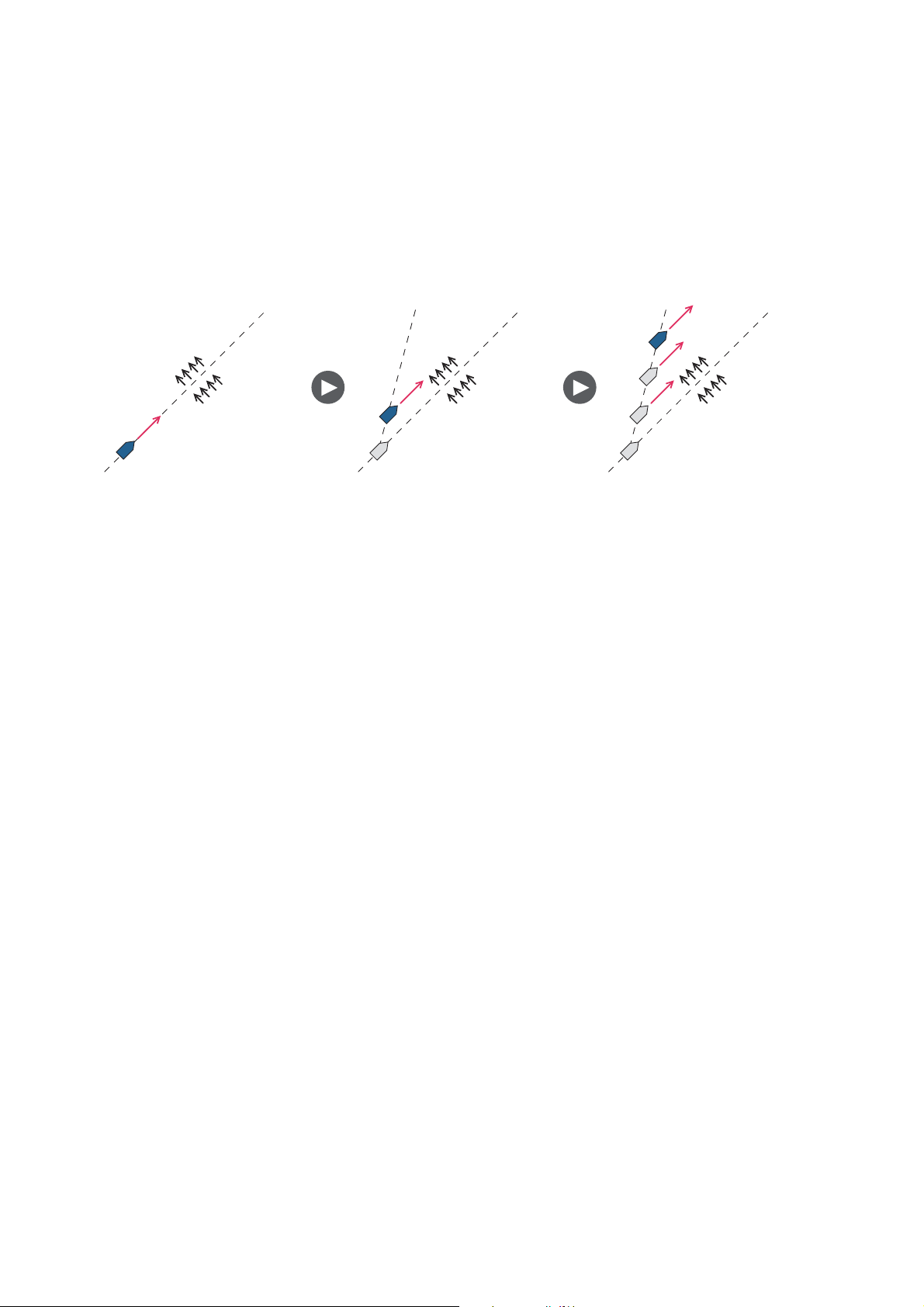
2.10.3 TACK mode
The TACK mode provides various tacking and gybing motions with the TURN key.
Fixed and auto tacking are available.
Tacking/gybing (fixed tack)
This function changes the current course by the degrees (set on menu) to port or starboard direction. There are two types of speed, SLOW (for gybing) and FAST (for tacking) in this mode. Use the tack mode when the true wind angle is less than 90°.
WIND OPTION
MODE TYPE: AWA
WIND TACK RUD ANGLE: 35
WIND DAMPING: OFF
FIXED TACK ANGLE: 20
RATE OF SLOW TACK: 3°/s
RATE OF FAST TACK: 20
TACK TIMER: OFF
°
°
/s
°
AWA
TWA
To start tacking/gybing, do the following:
1. Press the AUTO key to get the AUTO mode.
2. Press the TURN key to show the Turn menu.
SLOW TURN TO STBD
SLOW TURN TO STBD
NAVpilot-711NAVpilot-72
NAVpilot-700
3. Rotate the Course control knob to select a turn.
SLOW TURN TO PORT or SLOW TURN TO STBD: For gybing, when the wind
angle is larger than 120°. The boat slowly changes the heading angle.
2-25
Page 50

2. STEERING MODES
K
FAST TURN TO PORT or FAST TURN TO STBD: For tacking, when the true
wind angle is less than 90°. The boat rapidly changes the heading angle.
TACK ING
Degrees set on RATE OF FAST TACK
FAST mode (Rudder to starboard)
4. Push the Course control knob to start the turn.
The steering mode indication shows [BEGINNING TURN]. When the turn starts,
three beeps sound. You can set the timing between pressing the Course control
knob and starting tacking. See "How to set the tack timer" on page 2-31.
5. While confirming your heading, do jib sheet creasing and trimming operations.
Your boat starts turning in the direction selected at step 3
• The tacking angle can be set on the menu. See “How to set the fixed tack angle” on
the next page.
Wind direction
GYBING
Wind direction
Degrees set on RATE OF SLOW TAC
SLOW mode (Rudder to starboard)
• When the turning is completed, a beep sounds three times and the message "THE
TURN ENDED" appears.
How to set the rate of turn for FAST and SLOW tacking
The rate of turn is preset as 3° for SLOW and 20° for FAST. If you need to change the
value, do the following:
1. Press the MENU key to open the menu.
2. Rotate the Course control knob to select [OTHER MENU] then push the Course
control knob.
3. Rotate the Course control knob to select [WIND OPTION] then push the knob.
4. Rotate the Course control knob to select the value shown for [RATE OF SLOW
TACK] then push the knob.
5. Rotate the Course control knob to set the rate then push the knob.
6. Rotate the Course control knob to select the value shown for [RATE OF FAST
TACK] then push the knob.
7. Rotate the Course control knob to set the rate then push the knob.
8. Press the MENU key three times to close the menu.
2-26
Page 51

How to set the fixed tack angle
The fixed tacking mode requires the setting of tacking angle. Set the angle as follows:
1. Press the MENU key to open the menu.
2. Rotate the Course control knob to select [OTHER MENU] then push the Course
control knob.
3. Rotate the Course control knob to select [WIND OPTION] then push the knob.
4. Rotate the Course control knob to select the value shown for [FIXED TACK ANGLE] then push the knob.
5. Rotate the Course control knob to set the angle then push the knob.
6. Press the MENU key three times to close the menu.
2.10.4 Tacking in WIND mode (WIND TACK)
In the WIND mode, the degree and direction of tacking are automatically set so that
the boat receives the apparent wind on its opposite side with the same angle.
2. STEERING MODES
To start turning, do the following:
Wind direction
"
"
2-27
Page 52

2. STEERING MODES
1. In the WIND mode, press the TURN key to show the Turn menu.
The turning direction is determined according to the heading at the time the key is
pressed, as shown below.
Wind direction
STBD
10°
15°
15°
PORT
When the boat is in this area,
it cannot be turned in either direction.
15°
STBD
PORT
When the boat is in this
area, it may be turned
in either direction.
: Direction
available to turn
2. Rotate the Course control knob to select the direction to turn.
The choices are “TURN TO PORT” and “TURN TO STBD” (starboard). If you select an unavailable direction, the message "WIND DIRECTION OUT OF RANGE
FOR YOUR CHOICE." appears and the selection is refused.
2-28
Page 53

2. STEERING MODES
3. Push the Course control knob to start the turn.
The boat starts turning toward the selected direction until the heading changes
twice that set when the Course control knob was pressed. When the Course
control knob is pressed, for example, at the P (port) 50°, the boat turns until the
heading decreases 100°.
Wind direction
(apparent)
50
50
Tacking maneuver when wind angle is 50°
You can set the tacking start timing between pressing the Course control knob
and the start of turning. For details, see “How to set the tack timer” on page 2-31.
4. When the turning is completed, a beep sounds three times.
How to set maximum rudder angle for wind tacking
The tacking in the WIND mode requires the setting of maximum rudder angle. This angle is calculated automatically when the NAVpilot is installed. If you need to change
the value, do the following:
1. Press the MENU key to open the menu.
2. Rotate the Course control knob to select [OTHER MENU] then push the knob.
3. Rotate the Course control knob to select [WIND OPTION] then push the knob.
4. Rotate the Course control knob to select the value shown for [WIND TACK RUD
ANGLE] then push the knob.
5. Rotate the Course control knob to set the angle then push the knob.
6. Press the MENU key to three times close the menu.
2-29
Page 54

2. STEERING MODES
How to set the damping interval for wind data
You can set the damping interval for wind data to compensate for random fluctuation
in wind data. The higher the setting the more “smooth” the data. However, a high
damping interval causes delay in receiving wind data; the amount of delay equivalent
to the damping interval. Turn off wind damping if the wind data is received stably.
The port and starboard wind angles must be 55° or higher and the [MODE TYPE] must
be selected to [AWA] to use this function.
1. Press the MENU key to open the menu.
2. Rotate the Course control knob to select the current setting for [WIND DAMPING] then push the knob.
3. Rotate the Course control knob to select [ON] then push the knob.
4. Rotate the Course control knob to select the current wind damping interval then
push the knob.
OFF
ON
5. Rotate the Course control knob to set the interval then push the knob. The set-
ting range is 0.7 to 99 (sec.). See the table below for wind angle and wind damping
interval.
Wind
damping
(s)
User
setting
1.0
0 55.0 70.0 180.0 (deg)
Wind angle
6. Press the MENU key to close the menu.
2-30
Page 55

2. STEERING MODES
How to set the tack timer
You can set the amount of time to wait before starting a turn, after pushing the Course
control knob.
1. Press the MENU key to open the menu.
2. Rotate the Course control knob to select [OTHER MENU] then push the knob.
3. Rotate the Course control knob to select [WIND OPTION] then push the knob.
4. Rotate the Course control knob to select the value shown for [TACK TIMER]
then push the knob to show the tack timer options.
OFF
ON
5. Rotate the Course control knob to select [ON] then push the knob.
6. Rotate the Course control knob to select the current timer value then push the
knob.
7. Rotate the Course control knob to set the timer value then push the knob. The
setting range is 1-99 (sec.).
8. Press the MENU key three times to close the menu.
2.11 Safe Helm Mode
The safe helm mode, available with the Accu-Steer FPS 12V/24V drive unit, temporarily switches the NAVpilot to manual steering for the specified time interval when the
helm is steered in an automatic steering mode (AUTO, NAV, etc.). After cruising at angular velocity 3° or less per second for the set time, the safe helm mode is deactivated
and the previous automatic steering mode is restored. This prevents continued turning
of the helm. The mode and course indications flash when the safe helm mode activates.
Note: The safe helm mode is not available with Fantum Feedback
SETCSE
323°
HDG
T
RUDDER
323°
Flashing
TM
.
0°
20 10 5 5 10 20
Autopilot display 1 (NAVpilot-700)
SETCSE
SETCSE
T
RUDDER
Autopilot display 2 (NAVpilot-711, NAVpilot-720)
323°
20 10 5 5 10 20
0°
HDG T
323°
2-31
Page 56

2. STEERING MODES
How to set the safe helm mode
1. Open the menu in the STBY mode.
2. Use the Course control knob to select the [OTHER] menu then select [SAFE
HELM/P.ASSIST SETUP].
3. Use the Course control knob to select [SAFE HELM] then push the knob.
4. Use the Course control knob to select [ON] then push the knob.
5. Use the Course control knob to select [RETURN DELAY] then push the knob.
6. Rotate the Course control knob to set the return delay.
After cruising at angular velocity 3° or less per second for the set time, the safe
helm mode is deactivated and the AUTO or NAV mode is restored. The setting
range is 1-20 seconds.
SAFE HELM/P.ASSIST SETUP
SAFE HELM: ON
RETURN DELAY 5 SEC
SAFE HELM RESPONSE
POWER ASSIST: OFF
7. Use the Course control knob to select [SAFE HELM RESPONSE] then push the
knob.
SAFE HELM RESPONSE
RESPONSE: 6 PORT STBD
TURN HELM PORT/STBD TO
SET SAFE HELM RESPONSE
TIME. HIGHER VALUE =
FASTER RESPONSE
PUSH MENU KEY TO CONTINUE
8. Turn the Course control knob to set the response then push the knob. Turn the
helm to port or starboard. A beep sounds and the indication PORT or STBD on
the menu appear in reverse video.
9. Press the MENU key to finish.
2-32
Page 57

2.12 Power Assist Mode
The power assist mode, available with the Accu-Steer FPS 12V/24V type drive, customizes manual steering to your own preferences. The mode is available during the
safe helm mode and the STBY mode. The indication “PA” appears at top of the screen
when the mode is active.
Note: The power assist mode is not available with Fantum Feedback
PA
SETCSE
323°
HDG
T
RUDDER
323°
PA indication
2. STEERING MODES
TM
.
PA
0°
20 10 5 5 10 20
Autopilot display 1 (NAVpilot-700)
How to set the power assist mode
1. Open the menu in the STBY mode.
2. Use the Course control knob to select the [OTHER] menu then select [SAFE
HELM/P.ASSIST SETUP].
SETCSE
SETCSE
T
RUDDER
20 10 5 5 10 20
Autopilot display 2 (NAVpilot-711, NAVpilot-720)
SAFE HELM/P.ASSIST SETUP
SAFE HELM: ON
RETURN DELAY 5 SEC
SAFE HELM RESPONSE
POWER ASSIST: OFF
323°
HDG T
323°
0°
3. Use the Course control knob to select [POWER ASSIST] then push the knob.
2-33
Page 58

2. STEERING MODES
4. Use the Course control knob to select [ON] then push the knob.
When this is done the menu items for power assist appear.
5. Use the Course control knob to select [FOR SPEEDS UNDER] then push the
knob.
6. Rotate the Course control knob to set the highest speed at which power assist
activates. The setting range is 1.0 to 9.9 knots.
7. If you want power assist in the STBY mode, use the Course control knob to
set [POWER ASSIST STBY] to [ON].
8. Use the Course control knob to select [POWER ASSIST RUDDER SPEED] then
push the knob.
SAFE HELM/P.ASSIST SETUP
SAFE HELM: ON
RETURN DELAY 5 SEC
SAFE HELM RESPONSE
POWER ASSIST: OFF
FOR SPEEDS UNDER 3.0kn
POWER ASSIST STBY: ON
POWER ASSIST RUDDER SPEED
POWER ASSIST RUDDER SPEED
RUDDER SPEED: 10
TURN HELM PORT/STBD TO
SET RUDDER SPEED.
HIGHER VALUE = FASTER SPEED
PUSH MENU KEY TO CONTINUE
20 10 5 5 10 20
9. Turn the helm to port and starboard to set safe helm response time then push the
Course Control knob.
10. Press the MENU key to finish.
2-34
Page 59

3. ALARMS
Your NAVpilot has nine conditions which generate both audio and visual alarms:
watch alarm, deviation alarm, XTE (cross-track error) alarm, wind alarm (four types,
sailboats only), arrival alarm, speed alarm, depth alarm, water temperature alarm, and
log trip alarm.
When an alarm is violated, the buzzer sounds, and the alarm icon ( ) and a pop-up
message display appear (see section 5.5.3). You can see which alarm(s) has been violated by opening the Alarm Log, from the [SYSTEM SETUP] menu.
3.1 ALARM Menu
All alarm operations are done from the [ALARM] menu. To show the [ALARM] menu,
do as follows:
1. Press the MENU key to open the menu.
2. Rotate the Course control knob to select [OTHER MENU] then push the knob.
3. Rotate the Course control knob to select [ALARM] then push the knob.
Page 1 Page 2
ALARM
BUZZER: INTERNAL
BUZZER INTERVAL:
SHORT
WATCH ALARM: OFF
DEVIATION ALARM: 30°
XTE ALARM: OFF
WIND ALARM*
ARRIVAL ALARM: OFF
* Appears when Ship’s Characteristics is
set for “Sailboat”.
SPEED ALARM: OFF
DEPTH ALARM: OFF
TEMP ALARM: OFF
TRIP LOG: OFF
CLEAR TRIP LOG: NO
3-1
Page 60

3. ALARMS
3.2 Alarm Buzzer
You can select the buzzer from which to output the audio alarm as follows. Use the
external buzzer if the volume of the internal buzzer is not loud enough.
1. Rotate the Course control knob to select [BUZZER] from the ALARM menu then
push the knob.
2. Rotate the Course control knob to select [INTERNAL]
or [INTERNAL+EXTERNAL] then push the knob.
[INTERNAL]: Buzzer in Control Unit sounds.
[INTERNAL+EXTERNAL]: Buzzer in control unit and
external buzzer sound.
3. Push the Course control knob to confirm setting.
3.3 Buzzer Interval
The sound pattern for the alarms can be selected as follows.
1. Rotate the Course control knob to select [BUZZER INTERVAL] from the
[ALARM] menu then push the knob.
2. Rotate the Course control knob to select [SHORT], [LONG] or [CONTINUOUS]
then push the knob. [CONTINUOUS] releases the buzzer continuously.
200 ms
INTERNAL
INTERNAL +EXTERNAL
SHORT
LONG
CONTINUOUS
400 ms
SHORT pattern
3. Push the Course control knob to confirm setting.
800 ms
LONG pattern
800 ms
3-2
Page 61

3.4 Watch Alarm
The watch alarm periodically warns the helmsman to check the NAVpilot when in the
AUTO or NAV mode.
1. Rotate the Course control knob to select [WATCH ALARM] from the [ALARM]
menu then push the knob.
2. Rotate the Course control knob to select [OFF] or [ON] then push the knob. For
[OFF] got to step 5.
3. Rotate the Course control knob to select the current watch alarm value then
push the knob.
4. Rotate the Course control knob to set the time interval (1 to 99 min).
5. Push the Course control knob to confirm setting.
If the set time passes without operation, the buzzer sounds and the message "THE
SET TIME HAS PASSED" appears. Further, if three minutes elapses after the watch
alarm has sounded, the alarm becomes louder. Press any key to clear the alarm.
3. ALARMS
OFF
ON
3.5 Deviation Alarm
The deviation alarm sounds in the AUTO and NAV modes when the heading deviates
more than the deviation alarm value.
1. Rotate the Course control knob to select the current setting for [DEVIATION
ALARM] from the [ALARM] menu then push the knob.
2. Rotate the Course control knob to set the degree of deviation then push the
knob.
3-3
Page 62

3. ALARMS
3.6 XTE Alarm
The XTE alarm, which is available in the NAV mode, alerts you when the course error
has exceeded the XTE alarm setting.
Own ship
position
Intended
course
: Alarm
1. Rotate the Course control knob to select [XTE ALARM] from the [ALARM] menu
then push the knob.
OFF
ON
2. Rotate the Course control knob to select [OFF] or [ON] then push the knob. For
[OFF], press the MENU key consecutively to close the menu.
3. Rotate the Course control knob to select the current XTE alarm value then push
the knob.
4. Rotate the Course control knob to set the XTE alarm value.
5. Push the Course control knob to confirm setting.
Alarm
setting
Destination
3-4
Page 63

3.7 Arrival Alarm
The arrival alarm alerts you when you are within a specific distance from a waypoint.
Own ship
3. ALARMS
Alarm
range
: Alarm area
1. Rotate the Course control knob to select [ARRIVAL ALARM] from the [ALARM]
menu then push the knob.
2. Rotate the Course control knob to select [OFF] or [ON] then push the knob. For
[OFF], press the MENU key consecutively to close the menu.
3. Rotate the Course control knob to select the current arrival alarm value then
push the knob.
4. Rotate the Course control knob to set the arrival alarm value.
5. Push the Course control knob to confirm setting.
3.8 Speed Alarm
The speed alarm warns you when the speed of your boat is within, outside, over or
under the speed range setting. Requires speed data.
1. Rotate the Course control knob to select [SPEED ALARM] from the [ALARM]
menu then push the knob.
Waypoint
OFF
ON
OFF
UNDER
OVER
INSIDE
OUT OF RANGE
2. Rotate the Course control knob to select an option then push the knob. For
[OFF], press the MENU key consecutively to close the menu.
[OFF]: Turn the alarm off.
[UNDER]: Alarm sounds when ship’s speed is under the set value.
[OVER]: Alarm sounds when ship’s speed is over the set value.
[INSIDE]: Alarm sounds when ship’s speed is within the speed range set.
[OUT OF RANGE]: Alarm sounds when ship’s speed is outside the range set.
3. Rotate the Course control knob to set value.
For [INSIDE] and [OUT OF RANGE], set the upper and lower limits for the alarm.
For [OVER] and [UNDER], set a value.
4. Push the Course control knob to confirm setting.
3-5
Page 64

3. ALARMS
3.9 Depth Alarm
The depth alarm warns you when the bottom is shallower, deeper within or outside the
depth alarm setting. Requires a depth sensor.
1. Rotate the Course control knob to select [DEPTH ALARM] from the [ALARM]
menu then push the knob.
2. Rotate the Course control knob to select an option then push the knob. For
[OFF], press the MENU key consecutively to close the menu.
[OFF]: Turn the alarm off.
[SHALLOW]: Alarm sounds when depth is less than the set value.
[DEEP]: Alarm sounds when depth is greater than the set value.
[INSIDE]: Alarm sounds when depth is within the depth range set.
[OUT OF RANGE]: Alarm sounds when depth is outside the range set.
OFF
SHALLOW
DEEP
INSIDE
OUT OF RANGE
3. Rotate the Course control knob to set value.
For [INSIDE] and [OUT OF RANGE], set the upper and lower limits for the alarm.
For [SHALLOW] and [DEEP], set a value.
4. Push the Course control knob to confirm setting.
3.10 Water Temperature Alarm
There are five types of water temperature alarms: [UNDER], [OVER], [INSIDE], [OUT
OF RANGE] and [SHEAR]. Requires a water temperature sensor.
1. Rotate the Course control knob to select [TEMP ALARM] from the [ALARM]
menu then push the knob.
2. Rotate the Course control knob to select an option then
push the knob. For [OFF], press the MENU key consecutively to close the menu.
[OFF]: Turn the alarm off.
[UNDER]: Alarm sounds when water temperature is less
than the set value.
[OVER]: Alarm sounds when water temperature is higher
than the set value.
[INSIDE]: Alarm sounds when water temperature is within the depth range set.
[OUT OF RANGE]: Alarm sounds when water temperature is outside the range
set.
[SHEAR]: Alarm sounds when the temperature changes over the value set within
a minute.
OFF
UNDER
OVER
INSIDE
OUT OF RANGE
SHEAR
3-6
3. Rotate the Course control knob to set value.
[INSIDE], [OUT OF RANGE]: Set the upper and lower limits for the alarm.
[OVER], [UNDER], [SHEAR]: Set a value.
4. Push the Course control knob to confirm setting.
Page 65

3.11 Trip Distance Alarm, Trip Distance Reset
3.11.1 How to set the log trip alarm
The log trip alarm alerts when you have traveled a specific distance.
1. Rotate the Course control knob to select [TRIP LOG] from the [ALARM] menu
then push the knob.
OFF
ON
2. Rotate the Course control knob to select [OFF] or [ON] then push the knob. For
[OFF], press the MENU key consecutively to close the menu.
3. Rotate the Course control knob to set a value.
4. Push the Course control knob to confirm setting.
3.11.2 How to reset the trip distance
Follow the procedure below to reset the trip distance to zero.
3. ALARMS
1. Rotate the Course control knob to select [CLEAR TRIP LOG] from the [ALARM]
menu then push the knob.
NO
YES
2. Rotate the Course control knob to select [YES] then push the knob.
3. Push the Course control knob reset the trip distance to zero.
3-7
Page 66

3. ALARMS
3.12 Wind Alarms (for sailboats)
The WIND alarm, which is an alarm exclusively for sailboats, has four conditions which
generate both audio and visual alarms: heading change, wind deviation, true wind
speed and apparent wind speed.
To access the [WIND ALARM] menu, do the following:
1. Press the MENU key to open the menu.
2. Rotate the Course control knob to select [OTHER MENU] then push the knob.
3. Rotate the Course control knob to select [ALARM] then push the knob.
4. Rotate the Course control knob to select [WIND ALARM] then push the knob.
WIND ALARM
HEADING CHANGE ALARM OFF
WIND DEVIATION ALARM: 45°
TRUE WIND SPD ALARM: OFF
APP. WIND SPD ALARM: OFF
3.12.1 Heading change alarm
The heading change alarm sounds when own boat's heading changes remarkably by
the effects of true wind angle. Set the heading value and alarm range as shown in the
procedure which follows.
N
Range where the alarm occurs
1. Rotate the Course control knob to select [HEADING CHANGE ALARM] from the
[WIND ALARM] menu then push the knob.
2. Rotate the Course control knob to select [ON] then push the knob. The line below
[HEADING CHANGE ALARM] shows two values.
Heading value set (HDG)
Range setting (BND)
OFF
ON
3-8
3. Rotate the Course control knob to select the value (heading) at the far left then
push the knob.
4. Rotate the Course control knob to set value then push the knob to confirm set-
ting.
5. Rotate the Course control knob to select [BND] and then push the knob.
6. Rotate the Course control knob to set value then push the knob to confirm set-
ting.
Page 67

3.12.2 Wind deviation alarm
The wind deviation alarm sounds when the current wind angle is greater than the wind
angle limit set.
1. Rotate the Course control knob to select the value for [WIND DEVIATION
ALARM] from the [WIND ALARM] menu then push the knob.
2. Rotate the Course control knob to set value then push the knob to confirm setting.
3.12.3 True wind speed alarm
The true wind speed alarm warns you when the true wind speed is over or under the
true wind speed alarm setting.
1. Rotate the Course control knob to select [TRUE WIND SPD ALARM] from the
[WIND ALARM] menu then push the knob.
3. ALARMS
OFF
ON
2. Rotate the Course control knob to select [ON] then push the knob.
3. Rotate the Course control knob to select the current true wind speed alarm value
then push the knob.
4. Rotate the Course control knob to set the upper and lower limits for the alarm
then push the knob to confirm setting.
3.12.4 Apparent wind speed alarm
The apparent wind speed alarm warns you when the apparent wind speed is over or
under the apparent wind speed alarm setting.
1. Rotate the Course control knob to select [APP. WIND SPD ALARM] from the
[WIND ALARM] menu then push the knob.
OFF
ON
2. Rotate the Course control knob to select [ON] then push the knob.
3. Rotate the Course control knob to select the current apparent wind speed alarm
value then push the knob.
4. Rotate the Course control knob to set the upper and lower limits for the alarm
then push the knob to confirm setting.
3-9
Page 68

3. ALARMS
3.13 Alarm Log
The Alarm Log shows the date, time and alarm no. of violated alarms. To show this
log, select [ALARM LOG] from the [SYSTEM SETUP] menu. For a list of alarm numbers, see section 5.5.3.
ALARM LOG
2009/10/26 09:54:30 5105
Alarm no.
Time of alarm
Date of alarm
3-10
Page 69

4. HOW TO CUSTOMIZE YOUR NAVPILOT
This chapter shows you how to customize your NAVpilot to suit the characteristics of
your boat and your operational needs.
The items shown in each menu depend on the mode in use. For the STBY mode the
complete menu is shown. In the AUTO, NAV or WIND mode, only the menu items related to those modes are shown.
In the STBY mode, press the MENU key to show the STBY mode menu.
NAVpilot-700 NAVpilot-711/720
MESSAGE
SENSOR IN USE
RUDDER DRIVE LEVEL*
SEA STATE: FULL-AUTO
MANUAL PARAMETER
ADVANCED AUTO: ON
OTHER MENU
MESSAGE
SENSOR IN USE
CONTRAST/BRILLIANCE
RUDDER DRIVE LEVEL*
SEA STATE: FULL-AUTO
* Shown with Fantum FeedbackTM.
4.1 Parameter Setup (PARAMETER SETUP Menu)
The various parameters for your NAVpilot are set up from the [PARAMETER SETUP]
menu, which is in the [OTHER MENU].
PARAMETER SETUP
SEA STATE: FULL-AUTO
DEVIATION LEVEL: AUTO
MANUAL PARAMETER
TRIM GAIN*
SPEED CALCULATION: AUTO*
1
: AUTO
NAVpilot-700
2
1
*
Not shown with Fantum FeedbackTM.
2
*
Appears on page 2 of menu for
NAVpilot-711/720.
4-1
Page 70

4. HOW TO CUSTOMIZE YOUR NAVPILOT
4.1.1 Sea state
Your NAVpilot has an automatic adjustment feature which sets up the equipment according to ship's characteristics and sea state, for optimum performance in the AUTO,
NAV and WIND modes. In addition, a self-learning algorithm is incorporated: Parameters for rudder ratio, counter rudder and auto trim gains are constantly optimized
based on the steering history of your boat, and are stored in memory for future navigation.
How to select NAVpilot steering parameters
Set how the NAVpilot steers your boat as follows:
1. Rotate the Course control knob to select [SEA STATE] then push the knob.
FULL-AUTO
SEMI-AUTO
MANUAL-CALM
MANUAL-MODERATE
MANUAL-ROUGH
2. Rotate the Course control knob to select the option which best matches current
sea state then push the knob. For items other than [FULL-AUTO], go to step 4.
[FULL-AUTO]: Auto adjustment and self-learning are on.
[SEMI-AUTO]: Auto adjustment is on, self-learning is off.
[MANUAL-CALM]: Self-learning is off, using the parameter selected for calm sea.
[MANUAL-MODERATE]: Self-learning is off, using the parameters for a typical
normal sea state.
[MANUAL-ROUGH]: Self-learning is off, using preset parameters for a typical
rough sea state.
For normal, everyday operation, the [FULL-AUTO] mode is recommended. However, if you want the NAVpilot to steer the boat based on experience-related parameters, but you don't want the pilot to be in "self-learning" mode, choose the
[SEMI-AUTO] option.Note that the course keeping quality may be decreased if the
sea state is different from the experience-related parameters. This option is provided if you happen to be using the pilot in a situation that you do not anticipate
encountering again.
4-2
3. For [FULL-AUTO], set the deviation level as follows:
1) Rotate the Course control knob to select [DEVIATION LEVEL] then push the
knob.
AUTO
LEVEL
2) Rotate the Course control knob to select [AUTO] or[ LEVEL]. For [LEVEL],
you may set a value between 1 and 9. A lower number keeps the course more
precisely but the rudder may be turned more often. With a higher number, the
rudder is fixed, but the course may not be kept as precisely.
4. Push the Course control knob to confirm setting.
Page 71

4. HOW TO CUSTOMIZE YOUR NAVPILOT
How to manually set NAVpilot steering parameters
When [MANUAL-CALM], [MANUAL-MODERATE] or [MANUAL-ROUGH] is selected
as the sea state, set [MANUAL PARAMETER] as below.
You can set three parameters for the MANUAL function: Weather, Rudder gain and
Counter rudder.
1. Rotate the Course control knob to select [MANUAL PARAMETER] from the [PARAMETER SETUP] menu then push the knob. The display now looks like the one
shown below.
[CALM] [MODERATE] [ROUGH]
[WEATHER] 1° 2° 3°
[RUDDER GAIN] 3 5 10
[COUNTER RUDDER] 1 2 4
2. Rotate the Course control knob to select the setting of [WEATHER-CALM] then
press the knob.
3. Rotate the Course control knob to set value (0° to 10° for weather).
4. Push the Course control knob.
5. Set [WEATHER-MODERATE], [WEATHER-ROUGH] and [RUDDER GAIN] and
[COUNTER RUDDER] similarly (setting range: 0-10 for weather, 1-20 for rudder
gain, and 0-20 for counter rudder).
6. Press the MENU key to finish.
Guidelines for how to set SEA STATE
[WEATHER]: When the sea is rough, the boat's heading fluctuates to port and starboard. If the rudder is driven very often to maintain the set course, the helm mechanism may wear out. To prevent this, the weather adjustment makes the NAVpilot
insensitive to minute course deviations. You may choose a degree between 1° to 10°.
Until the course deviation exceeds the selected setting, steering to correct the heading
will not be initiated.
The illustration at the top of the next page shows boat's track lines with weather setting
3° and 7°. When 7° is set, for example, the rudder is not driven until the course deviation exceeds 7°. Increasing the setting reduces activation of the steering gear, however the boat tends to zigzag. When the sea is calm, set a smaller value.
7°
3°
Weather = 3° Weather = 7°
[RUDDER GAIN]: When the boat's heading deviates from the set course, the NAVpilot
adjusts the rudder to correct it. The rudder angle (number of degrees) which is steered
against every degree of course deviation is known as the rudder gain.
4-3
Page 72

4. HOW TO CUSTOMIZE YOUR NAVPILOT
The following illustrations show how many degrees the NAVpilot steers the rudder in
order to nullify 4 degrees of course deviation with various settings of the rudder gain.
Rudder gain = 1° Rudder gain = 2° Rudder gain = 3°
4°
Rudder angle = 4° x 1=4° Rudder angle = 4° x 2=8° Rudder angle = 4° x 3=12°
Set rudder gain so that the boat does not make frequent yaw. The figure shown below
provides general guidelines for setting rudder gain.
Fast
Calm
Light
4°
Speed
Sea State
Load Condition
4°
Slow
Rough
Heavy
Low
[COUNTER RUDDER]: If the boat is heavily loaded, the heading could change excessively because of inertia. This phenomenon causes the vessel to "overshoot" the intended course. If this happens, the NAVpilot will steer the rudder to the opposite side
and the heading will turn in opposite direction excessively again. In an extreme case
the heading oscillates several times until it finally settles in the new course. An adjustment known as "counter rudder" prevents this kind of oscillation.
Counter rudder is usually not required for small boats. When your boat zigzags a lot
before settling in the new course, increase the counter rudder setting.
RUDDER GAIN
High
4-4
Page 73

Counter rudder:
small setting
Counter rudder:
proper setting
4. HOW TO CUSTOMIZE YOUR NAVPILOT
Large course error
Intended
course
The counter rudder feature functions to smoothly
return ship's heading toward intended course.
Slow
Light
Low
4.1.2 Trim gain
The NAVpilot continually monitors the boat's trim in order to keep the trim sensitivity
optimum. A lower setting is common because boat's trim usually does not change
quickly. A large number changes the trim compensation value more frequently. Too
high of a setting may result in the following problems.
Note: Trim gain is not available with Fantum Feedback
• Trim sensitivity is over-affected, resulting that a trim appears in both port and star-
board directions alternately.
• Trim compensation mechanism responds to the yawing, resulting in more serious
oscillation of ship's heading.
To automatically set the trim, do as follows:
1. Rotate the Course control knob to select [TRIM GAIN] from the [PARAMETER
SETUP] menu.
Speed
Load Condition
COUNTER RUDDER
TM
Fast
Heavy
High
.
2. Push the Course control knob to show the options for [TRIM
GAIN].
3. Rotate the Course control knob to select [AUTO] or [MANUAL]
then push the knob. For [AUTO] go to step 6.
4. Rotate the Course control knob to select the current value and push the knob.
5. Rotate the Course control knob to set a value (1 to 20. The default value is automatically calculated according to length of your boat, entered on the [SHIP’S
CHARACTERISTICS] menu at installation.
6. Push the Course control knob to finish.
AUTO
MANUAL
4-5
Page 74

4. HOW TO CUSTOMIZE YOUR NAVPILOT
4.1.3 Speed calculation
Speed is normally entered automatically, from your navigator. If the navigator fails,
manually enter speed.
1. Rotate the Course control knob to select [SPEED CALCULATION] from the [PARAMETER SETUP] menu.
2. Push the Course control knob to show the options for [SPEED CALCULATION].
3. Rotate the Course control knob to select [AUTO] or [MANUAL] then push the
knob. For [AUTO] go to step 4. For [MANUAL], do as follows:
1) Rotate the Course control knob to select the current value then push the
knob.
2) Rotate the Course control knob to set a value (0.1 - 99.0).
4. Push the Course control knob to finish.
AUTO
MANUAL
4.2 Rudder Drive Level (For Fantum Feedback
For Fantum FeedbackTM, the driving power of steering can be adjusted by the rudder
drive level. The higher the setting is, the greater the rudder is turned.
1. Press the MENU key.
2. Rotate the Course control knob to select [RUDDER DRIVE LEVEL] then push
the knob.
3. Rotate the Course control knob to set a value (1 - 20) then push the knob.
4. Press the MENU key to finish.
TM
)
4-6
Page 75

4.3 Net Towing
When a boat is towing fishing gear its stern is "dragged" by the net. This causes the
boat to stray from its intended course. To keep the boat on course, you need to adjust
the trim manually, which can be bothersome. If you do not want to be bothered with
trim adjustments, you can enable the automatic towing function to have the trim automatically adjusted. This feature is useful for trawlers and purse seiners.
[SHIP’S CHARACTERISTICS] must be set for “other than sailboat” to get this feature.
4. HOW TO CUSTOMIZE YOUR NAVPILOT
Note: This feature is not available with Fantum Feedback
TM
.
1. Open the [OTHER MENU] followed by the [AUTO OPTION] menu.
2. Rotate the Course control knob to select [NET TOWING AUTO] then push the
knob.
OFF
ON
3. Rotate the Course control knob to select [OFF] or [ON].
4. Push the Course control knob to finish.
Note that you must keep the boat on a straight course before the AUTO mode is selected.
4.4 Course After Operation of a Remote Controller
Select the course to follow after a remote controller is operated.
Note: This feature is not available with Fantum Feedback
TM
.
Previous course
New course
Remote
controller: OFF
PRESENT COURSE mode
Remote
controller: ON
Previous course
Remote
controller: OFF
Remote
controller: ON
PREVIOUS COURSE mode
1. Open the [OTHER MENU] followed by the [AUTO OPTION] menu.
2. Rotate the Course control knob to select [CSE AFTER REMOTE] then push the
knob.
PREVIOUS COURSE
PRESENT COURSE
3. Rotate the Course control knob to select desired option.
4. Push the Course control knob to finish.
4-7
Page 76

4. HOW TO CUSTOMIZE YOUR NAVPILOT
4.5 Nav Data Source
Select the source of nav data to use in the NAV mode.
1. Select [OTHER MENU] followed by [NAV OPTION].
2. Rotate the Course control knob to select [NAV DATA SOURCE] then push the
knob.
NAV DATA SOURCE
DATA SOURCE: SOURCE1
SOURCE1: - - - - - - - - - - - - - SOURCE2: - - - - - - - - - - - - - -
3. Rotate the Course control knob to select [DATA SOURCE] then push the knob.
4. Rotate the Course control knob to select source then push the knob. If you have
more than one source of nav data, you can select [BOTH]. In this case, the nav
data fed by [SOURCE2] is used when that of [SOURCE1] is not available.
SOURCE1
SOURCE2
BOTH
5. Rotate the Course control knob to select [SOURCE1] then push the knob.
- - - - - - - - - - - - - -
NAVNET3: 000C2F
PORT2
If you have some equipment which outputs nav data, the name appears in the window. In the example above, a NavNet 3 equipment, with unique number of
000C2F, is connected.
6. Rotate the Course control knob to select source then push the knob. If you have
more than one device that outputs nav data, you can select it at [SOURCE2].
Note: If you have NavNet vx2 equipment connected and it is synchronized with the
NAVpilot ([NAVNET2] turned on in the [NAV OPTION] menu, [SOURCE2] is automatically selected.
4.6 NavNet vx2 Synchronization
The NAVpilot goes to the NAV mode when it receives a P sentence (proprietary FURUNO sentence) from a NavNet vx2 equipment. For example, “autopilot information”.
You can turn this feature on or off as follows:
4-8
1. Open the [OTHER MENU] followed by the [NAV OPTION] menu.
2. Rotate the Course control knob to select [NAVNET2] then push the knob.
OFF
ON
3. Rotate the Course control knob to select [OFF] or [ON].
4. Push the Course control knob to finish.
Page 77

4.7 SYSTEM SETUP Menu
The [SYSTEM SETUP] menu provides various functions which once set do not require
frequent adjust. Set the items in this menu according to operational needs, current environment, etc. To open this menu, select [OTHER MENU] followed by [SYSTEM
SETUP].
4. HOW TO CUSTOMIZE YOUR NAVPILOT
Page 1
SYSTEM SETUP
KEY BEEP: OFF
BUZZER VOL: LARGE
ARROW KEY: DODGE
TURN ANGLE: 15
KEY LOCK: UNLOCK
PANEL DIMMER: 8
PASSWORD: 0000
PASSWORD FUNCTION: OFF
RECEIVE SCREEN: OFF
Page 2
SYSTEM SETUP
SAVE USER SETTING: NO
LOAD USER SETTING: NO
SAVE DISPLAY SETTING: NO
LOAD DISPLAY SETTING: NO
ALARM LOG
SIM/DEMO: OFF
DIAGNOSTIC: OFF
DISPLAY DATA SELECT MENU
SYSTEM SETUP menu (shown: NAVpilot-700)
SYSTEM SETUP menu description
Item Description Options
[KEY BEEP] Turn the key beep on or off. [ON], [OFF]
[BUZZER VOL] Set the volume of the buzzer, on
the NAVpilot-700.
Page 3
SYSTEM SETUP
SYSTEM DATA
[SMALL], [LARGE]
[ARROW KEY] Set the function of an arrow key
when pressed to dodge an obstruction in the AUTO and WIND
modes.
[TURN ANGLE] Set the angle of User turn in the
Turn mode.
[KEY LOCK] Prevent operation of the control
unit.
[PANEL DIMMER] Set the backlighting level for the
panel dimmer.
[PASSWORD] Assign a four-digit password to
use to unlock the keys and menu
on the control unit.
[PASSWORD
FUNCTION]
Activates or deactivates password requirement. Select ON to
require a password to access
menus. If the password is entered
correctly, the menu becomes operative and the option setting for
this item changes to OFF.
[DODGE], [5°], [10°], [MANUAL]. For [MANUAL], select
degree of turn from 1°-90°.
15°-360°, 15° steps
[LOCK], [UNLOCK]. The
“LOCK” icon ( ) appears
when [LOCK] is selected.
1-8
0000-9999
[ON], [OFF]
4-9
Page 78

4. HOW TO CUSTOMIZE YOUR NAVPILOT
Item Description Options
[RECEIVE
SCREEN]
[SAVE USER SETTING]
[LOAD USER SETTING]
[SAVE DISPLAY
SETTING]
[LOAD DISPLAY
SETTING]
[ALARM LOG] Show the alarms generated. See
For multiple control units, you can
copy the settings of one control
unit to another. When you receive
settings from a control unit of a
different size than own, the following rule applies:1DIN
1BOX 2BOXES 2BOXES
3BOXES
Save current settings as user default settings.
Load user default settings. The
equipment is automatically restarted to restore saved user settings.
Save all display-related settings. [NO], [YES]
Load currently saved display-related settings.
section 3.13.
2DIN
[NO], 1-6 (actual number depends on number of control
units connected)
[NO], [YES]
[NO], [YES]
[NO], [YES]
[SIM/DEMO] Activate and deactivate the dem-
onstration mode. DO NOT use
this function on board your boat; it
is intended for use by service
technicians. "SIM" appears at the
top right corner when the simulation mode is enabled.
[DIAGNOSTIC] Perform various diagnostics on
the NAVpilot system. See
section 5.3.
[DISPLAY DATA
SELECT MENU]
[SYSTEM DATA] Show system data. See
Set and select the data to show in
the STBY, AUTO, NAV, WIND,
TM
and FishHunter
page 1-11 for the procedure.
section 5.4.
modes. See
[OFF], [DEMO SLIDE
SHOW], [SIMULATOR],[SIM
W/DRIVE].
4-10
Page 79

4.8 Menu Shortcuts
You can create menu shortcuts to the STBY mode menu for menu items which you
often use. Up to 20 shortcuts can be created.
4.8.1 How to create a menu shortcut
The procedure below shows you how to create a menu shortcut for the arrival alarm.
1. Open the STBY mode menu.
2. Select the menu item for which you want to create a menu shortcut. For example,
select [ARRIVAL ALARM] from the [ALARM] menu.
3. Long press the MENU key to show the following prompt.
+++ MENU ENTRY +++
ARE YOU SURE?
YES-PUSH ENTER KNOB
NO-PUSH MENU KEY
4. HOW TO CUSTOMIZE YOUR NAVPILOT
4. Press the Course control knob to create the shortcut. The shortcut is then added
to the STBY mode menu.
MESSAGE
SENSOR IN USE
SEA STATE: FULL-AUTO
MANUAL PARAMETER
ADVANCED AUTO: ON
ARRIVAL ALARM: OFF
OTHER MENU
4.8.2 How to delete a menu shortcut
1. Open the STBY mode menu.
2. Select the menu item to delete.
3. Long press the MENU key to show the following prompt.
- - - MENU DELETE - - ARE YOU SURE?
YES-PUSH ENTER KNOB
NO-PUSH MENU KEY
Menu shortcut
4. Press the Course control knob to delete the shortcut.
4-11
Page 80

4. HOW TO CUSTOMIZE YOUR NAVPILOT
This page is intentionally left blank.
4-12
Page 81

5. MAINTENANCE, TROUBLESHOOTING
This chapter provides the maintenance and troubleshooting procedures.
WARNING
ELECTRICAL SHOCK HAZARD
Do not open the equipment.
This equipment uses high
voltage that can cause
electrical shock.
0nly qualified persons can
work inside the equipment.
5.1 Preventive Maintenance
Regular maintenance is necessary for best performance. Create a maintenance
schedule which includes the items shown below.
Item Check point Remedy
Control unit connectors
LCD Dust on the LCD dims pic-
Check for tight connection. Tighten loosened connectors.
ture.
D
sealant or contact spray to plastic
parts or equipment coating.
Those items contain products that can
damage plastic parts and equipment
coating.
NOTICE
o not apply paint, anti-corrosive
Clean the LCD carefully to prevent
damage, with tissue paper and an
LCD cleaner. To remove dirt or salt
deposits, use an LCD cleaner and
wipe slowly with lens paper so as to
dissolve the dirt or salt. Change the
paper frequently so the salt or dirt will
not damage the LCD. Do not use solvents like thinner, acetone or benzine
for cleaning.
Ground terminal Check for tight connection
and corrosion
Clean or replace the ground wire as
necessary.
5-1
Page 82

5. MAINTENANCE, TROUBLESHOOTING
5.2 Replacement of Fuse
Two fuses (125V 4A) in the processor unit protect the equipment from reverse polarity
of the ship's mains and equipment fault. If a fuse blows, you cannot turn on the power.
Have a qualified technician check the set.
WARNING
Use the proper fuse.
Use of a wrong fuse can cause fire or
damage the equipment.
Parts name Type Code no. Remarks
Fuse FGMB 125V 4A PBF 000-157-482-10 Supplied as spare
parts
5.3 Diagnostics
Your NAVpilot contains the diagnostics that check the processor unit, control unit,
NMEA 0183 input/output, CAN bus, keyboard, screen, rudder, and helm (Accu-Steer
FPS 12V/24V helm sensor only). The tests are for use by service technicians, but you
can do the tests to help the technician in troubleshooting.
5.3.1 Diagnostic menu
1. Press the MENU key to open the menu.
2. Rotate the Course control knob to select [OTHER MENU] then push the knob.
3. Rotate the Course control knob to select [SYSTEM SETUP] then push the knob.
4. Rotate the Course control knob to select the current setting for [DIAGNOSTIC]
then push the knob.
OFF
PROCESSOR UNIT
CONTROL UNIT
NMEA0183 TEST
CAN BUS TEST
KEYBOARD TEST
SCREEN TEST
RUDDER TEST
HELM SENSOR*
5-2
*: Appears when the Accu-Steer FPS 12V/24V is installed.
5. Rotate the Course control knob to select the item to test then push the knob to
start the test.
6. Press the MENU key continuously to quit the test and close the menu.
Page 83

5.3.2 Processor unit test
This test checks the processor unit for correct operation. Open the diagnostic test options window, select [PROCESSOR UNIT] then push the Course control knob. The
results for the ROM, RAM and RUDDER ANGLE are shown as OK or NG. If NG appears, repeat the test. If the error condition continues, contact your dealer.
PROCESSOR UNIT ID: 39768
ROM: OK 6454007-**.**
6454009-**.**
RAM: OK BACKUP: OK
RUDDER ANGLE: OK 0°
BYPASS/CLUTCH: 0.7A
RC1/RC2: OFF -1° /OFF -2°
INPUT VOLTAGE: 24.5 V
PORT1/PORT2/CAN: - -/- -/OK
CAN ID: 39713 CPU/PWR: */*
*: Version no.
**.**: Program version no.
5. MAINTENANCE, TROUBLESHOOTING
For Fantum FeedbackTM, “FANTUM
FEEDBACK” is displayed.
Not shown with Fantum FeedbackTM.
[ROM]: "OK" for normal, program number
[RAM]: RAM test, "OK" for normal
[BACKUP]: Backup data test, "OK" for normal.
[RUDDER ANGLE]: "OK" for normal, actual rudder angle.
[BYPASS/CLUTCH]: Bypass/clutch amperage. ("NOT PRESENT" shown in case of
no connection.)
[RC1/RC2]: Remote controller state (ON or OFF) and rudder signal input value. "NOT
USED" shown in case of no connection.
[INPUT VOLTAGE]: Voltage.
[PORT1/PORT2/CAN]: I/O test for PORT1/PORT2/CAN (CAN bus). OK for normal.
[CAN ID]: ID of CAN bus equipment.
5.3.3 Control unit test
This test checks the control unit for correct operation. Open the diagnostic test options
window, select [CONTROL UNIT] then push the Course control knob. The results for
[ROM], [RAM], [BACKUP], and [COMMUNICATION] are shown as OK or NG (No
Good). If NG appears, repeat the test. If the error condition continues, contact your
dealer.
CONTROL UNIT
ROM: OK 6454011-**.**
6454010-**.**
RAM: OK BACKUP: OK
COMMUNICATION: OK
CONTROLLER ID: 2
CAN ID: 0 CPU:*
*: Version no.
**.**: Program version no.
5-3
Page 84

5. MAINTENANCE, TROUBLESHOOTING
5.3.4 NMEA0183 test
This test checks for correct input and output of NMEA 0183 data from PORT1 and
PORT2. The test is for service technicians and requires a special test connector. (If
the test is done without the connector, the results are shown as “- -”.)
Open the diagnostic test options window, select [NMEA0183 TEST] then push the
Course control knob. The results are shown as OK or "- -". For any "- -", repeat the
test. If the error condition continues, contact your dealer.
NMEA0183 TEST
PORT1: OK
PORT2: OK
5.3.5 CAN bus test
This test checks the CAN bus network. Open the diagnostic test options window, select [CAN BUS TEST] then push the Course control knob. The results are shown as
OK or NG (No Good). ("- -" appears when there is no CAN bus connection.) If NG appears, repeat the test. If the error condition continues, contact your dealer.
CAN BUS TEST
CAN BUS: OK
5-4
Page 85

5.3.6 Keyboard test
The keyboard test checks the key panel on the control unit. Open the diagnostic test
options window, select [KEYBOARD TEST] then push the Course control knob.
Press each key and the Course control knob. The related on-screen location fills in
black if the key or knob is normal. Rotate the Course control knob. The figure inside
the circle on the screen counts up or down with knob rotation.
5. MAINTENANCE, TROUBLESHOOTING
KEYBOARD TEST
PUSH MENU KEY THREE TIMES
TO RETURN
NAVpilot-700
5.3.7 Screen test
The screen test checks the control unit for correct presentation of black and white
tones. Open the diagnostic test options window, select [SCREEN TEST] then push the
Course control knob. Push the Course control knob to change the screen. Press
the MENU key continuously to quit the test and close the menu.
SCREEN TEST
CHANGE TEST PATTERN?
YES ... PUSH ENTER KNOB.
PUSH MENU KEY TO RETURN.
000
KEYBOARD TEST
000
PUSH MENU KEY THREE TIMES
TO RETURN
NAVpilot-711
KEYBOARD TEST
000
PUSH MENU KEY THREE TIMES
TO RETURN
NAVpilot-720
(Flashing)
5-5
Page 86

5. MAINTENANCE, TROUBLESHOOTING
5.3.8 Rudder test
The rudder test checks drive type, presence or absence of bypass/clutch circuit, rudder deadband, rudder speed, rudder duty*, and rudder angle.
* The rudder control value required to obtain rudder speed of 5°/sec. For solenoid systems, ship’s characteristics=sailboat, the indication is 100% always. For ship’s characteristics=sailboat, the message "Rudder speed is too slow to control the vessel. The
vessel may not be controlled properly." does not appear when the rudder speed is
greater than 5°/sec; however, this is not a sign of malfunction.
When the rudder reference unit is installed
Open the diagnostic test options window, select [RUDDER TEST] then push the
Course control knob. You are asked to center the rudder. Center the rudder then
push the Course control knob to start the test.
RUDDER SETUP AND AUTO TEST
DRIVE TYPE: REVERSIBLE 12V
BYPASS/CLUTCH: NOT PRESENT
DB : 0.5
RUDDER DUTY: 100%
°
SPD: 5.2 °/S
20 10 5 5 10 20
The result display
For Fantum Feedback
㪫㪤
Note 1: For Fantum FeedbackTM, the rudder test does not check presence or absence
of bypass/clutch circuit, the rudder deadband, and rudder angle.
TM
Note 2: For Fantum Feedback
, this rudder test is the different from it at installation
in the following points.
• The adjustment of the rudder speed is not available.
• The result calculated by the rudder test is not reflected to the control of the NAVpilot.
1. Select [RUDDER TEST] in the [DIAGNOSTIC] menu then push the Course con-
trol knob.
USE WHEEL TO
CENTER RUDDER BEFORE
RUDDER TEST.
ARE YOU SURE?
YES ENTER NO MENU
2. Center the rudder then push the Course control knob.
5-6
3. Turn the helm or press the W (or X) key hard-over to PORT/STBD then push the
knob.
4. Long press the W (or X) key hard-over to the opposite direction from step 3.
Page 87

5. MAINTENANCE, TROUBLESHOOTING
5. When the rudder is reached to hard limit, release the W (or X) key.
HAS THE RUDDER REACHED
THE HARD LIMIT?
YES ENTER NO MENU
6. If the rudder reached to the hard limit properly, select [YES]. If not, select [NO] to
display the message as below.
RUDDER TEST IS
UNCOMPLETED.
RETRY?
YES ENTER NO MENU
If retry the rudder test, select [YES] and go back to step 3. If not, select [NO] to
abort the rudder test.
7. The result of the rudder test is displayed.
RUDDER TEST
DRIVE TYPE: REVERSIBLE 12V
°
SPD: 5.2
/S
RUDDER DUTY: 100%
RUDDER DRIVE LEVEL: 6
PUSH MENU KEY TO RETURN
The result display
The result message
When the rudder test is completed, a message announces the results of the test.
Message Meaning
Rudder test completed. Rudder tested OK.
Rudder speed is too fast to control the vessel. The vessel
may not be controlled properly.
Rudder speed is too slow to control the vessel. The vessel may not be controlled properly.
Deadband is too big to control the vessel. The vessel may
not be controlled properly.*
Deadband is too big rudder speed is too fast to control the
vessel. The vessel may not be controlled properly.*
Deadband is too big rudder speed is too slow to control
the vessel. The vessel may not be controlled properly.*
Rudder test failed.*
Rudder speed is too fast.
Rudder speed is too slow.
Deadband is too large.
Deadband is too large; rudder speed is too fast.
Deadband is too large; rudder speed is too slow.
*: Not shown with Fantum Feedback
TM
.
5-7
Page 88

5. MAINTENANCE, TROUBLESHOOTING
5.3.9 Helm sensor test
The helm sensor test checks the connection between the Accu-Drive FPS 12V/24V
helm sensor and the processor unit. (The test is not available for other types of helm
sensors.) Turn the helm to port or starboard and then in the opposite direction. If the
connection is normal, the message "HELM SENSOR TEST COMPLETED." appears.
For failure, "HELM SENSOR TEST FAILED." appears. Check that your helm sensor
is Accu-Drive FPS 12V/24V. Also, check that the helm sensor is correctly connected
to TB4.
Note: The helm sensor test is not available with Fantum Feedback
5.4 System Data
The system data display allows you to confirm the equipment and drive system status.
To show this display, open the [SYSTEM MENU], select [SYSTEM DATA] then push
the Course control knob.
[INPUT VOLTAGE]: Voltage input to the NAVpilot.
[CONTROLLER ID]: ID of the controller that displays the system data.
[DRIVE TYPE]: Drive type used with the NAVpilot.
[BYPASS/CLUTCH]
[P/C TEMP]: Temperature of processor unit / control unit.
[MOTOR DRIVE CUR]: Motor drive current. Max. value is 25.0 A.
[BYPASS/CLUTCH CUR]*: Bypass/clutch current. Max. value is 3.0 A.
INPUT VOLTAGE: 24.4 V
CONTROLLER ID: 2
DRIVE TYPE: REVERSIBLE 24V
BYPASS/CLUTCH: NOT PRESENT
P/C TEMP: 71.3
MOTOR DRIVE CUR: 10.0 A
BYPASS/CLUTCH CUR*: 0.0 A
*
: Presence or absence of bypass/clutch.
°F/91.1°F
TM
.
5-8
*: Not shown with Fantum Feedback
TM
.
Page 89

5.5 Messages
Your equipment displays messages to alert you to potential equipment problem and
operation status.
5.5.1 Message pop-up display
When the system detects alarm violation, error, etc., the buzzer sounds and an error
message pop-up display appears. The illustration below shows the message for rudder drive error. For any error message, turn off the NAVpilot and have a qualified technician check the drive circuit.
RUDDER DRIVE ERROR
PLEASE TURN OFF AND
CHECK DRIVE CIRCUIT
5.5.2 Message board
The message board contains the information about the latest alarm/error messages.
To show the message board, press the MENU key to open the menu. [MESSAGE] is
selected; push the Course control knob.
5. MAINTENANCE, TROUBLESHOOTING
ALARM 1/1
Message no.,
message category
(ALARM, CAUTION
ERROR, FAIL)
0013 FAIL
RUDDER DRIVE ERROR
PUSH MENU KEY TO RETURN
5.5.3 Message description
Error
no.
Alarm
5101 “DEVIATION ALARM” Deviation alarm violated.
5103 “WIND DEVIATION ALARM” Wind deviation alarm violated.
5105 "ARRIVAL ALARM" You are nearing a waypoint.
5107 "CROSS TRACK ERROR" Your boat is off course by the amount set
Error message Meaning, remedy
MESSAGE
Message no./
total no. of messages
Message
on the XTE alarm.
5203 "THE PRESET TIME HAS
PASSED"
5301 "HEADING CHANGE ALARM" Heading change alarm violated.
5303 "TRUE WIND SPEED ALARM" True wind alarm violated (sailboats only).
The watch alarm has activated. Operate
any key to confirm presence.
5-9
Page 90

5. MAINTENANCE, TROUBLESHOOTING
Error
no.
5305 "APP WIND SPEED ALARM" Apparent wind alarm violated (sailboats
5307 "SPEED ALARM" Speed alarm violated.
5309 "WATER TEMP ALARM" Water temperature alarm violated.
5311 "DEPTH ALARM" Depth alarm violated.
5313 "TRIP ALARM" Your boat has travelled the distance set
Error
1101 "TOO FAST TO GO FISHING
MODE. PLEASE SLOW DOWN
LESS THAN 10 kn."
1201 "COMMUNICATION ERROR" No communication between processor
1203 "FU REMOTE CONTROLLER
ERROR"
Error message Meaning, remedy
only).
for the trip alarm.
Set speed below 10 knots then go to respective mode.
unit and control unit. Turn off power.
Check remote controller.
1301 "MISSING HEADING DATA" Check heading sensor.
1303 "HEADING DATA IS SHIFTED" Heading data has changed abruptly.
Check heading sensor.
1305 "NO SPEED DATA. PLEASE
CHECK SPEED SOURCE OR
ENTER MANUAL SPEED VALUE IN PARAMETER SETUP."
1307 "NO WIND DATA" Check wind sensor.
1309 "WIND DATA IS SHIFTED" Wind data has changed abruptly. Check
1311 "NO NAV DATA. WAIT FOR 1
SECONDS."
1315 "DEGRADATION OF NAV DATA
QUALITY"
1317 "NO POSITION DATA" Check position-fixing equipment.
1901 "RATE SENSOR ERROR" Check rate sensor.
1903 "BACKUP ERROR" All user and engineer default settings are
Check the speed source or enter the
speed manually.
wind sensor.
Check nav data sensor.
Check nav data sensor.
restored. Reenter installation settings.
5-10
Fail
0001 "DRIVE UNIT ERROR" Turn off power
0003 "DRIVE UNIT OVERLOAD" Turn off power.
0005 "DRIVE UNIT IS OVER- HEAT-
ED"
0007 "BYPASS/CLUTCH DRIVE ER-
ROR"
Temperature of drive circuit is higher than
80°C(176°F). Turn off power.
Bypass/clutch error. Turn off power.
Page 91

5. MAINTENANCE, TROUBLESHOOTING
Error
no.
0009 "BYPASS/CLUTCH IS OVER-
LOADED"
0011 "BYPASS/CLUTCH IS SHORT-
ED OUT"
0013 "RUDDER DRIVE ERROR" Turn off power.
0017 "RUDDER ANGLE ERROR" Turn off power.
0301 "COMMUNICATION ERROR" No communication between processor
Notice
2001 "INPUT VOLTAGE IS UNDER
LIMIT"
2003 "INPUT VOLTAGE IS OVER
LIMIT"
2101 "NAV MODE PARAMETER ER-
ROR"
Error message Meaning, remedy
Bypass/clutch overload. Turn off power.
Bypass/clutch is shorted. Turn off power.
unit and all control units. Turn off power.
Input voltage under limit. Check power
supply.
Input voltage over limit. Check power supply.
Invalid parameter entered in NAV mode.
Reenter parameter.
2105 "START TO TURN BY FISHING
MODE"
2107 "CIRCLE MODE STOPPED" Circle mode was stopped.
2109 “MODE WAS CHANGED” Steering mode changed.
2201 "WARNING. REMOTE CON-
TROLLER’S SW IS ON"
2203 "THE SET TIME HAS PASSED" Watch alarm has activated.
2301 "HEADING SOURCE ARE
CHANGED"
2303 "WIND SOURCE ARE
CHANGED"
2305 "POSITION SOURCE ARE
CHANGED"
2307 “SPEED SOURCE HAS
CHANGED”
2330 "ARRIVED AT WAYPOINT" Arrival alarm alerts you to arrival at final
Boat is starting to turn after dodge operation.
Remote controller switch is ON. Turn it
OFF to continue operation.
Heading source changed.
Wind source changed.
Position source changed.
Source of speed changed.
waypoint.
2340 "WAYPOINT WAS CHANGED" Switching to next waypoint.
2360 "NO WATER TEMP DATA" Check water temperature sensor.
2362 "NO DEPTH DATA" Check depth sensor.
2370 “HELM SENSOR ERROR” Check helm sensor.
2901 "NO COMPASS ADJUSTMENT
DATA"
Check heading sensor.
5-11
Page 92

5. MAINTENANCE, TROUBLESHOOTING
5.6 Sensor in Use Display
The SENSOR IN USE display provides a comprehensive list of the sensors connected
to your NAVPILOT.
1. In the STBY mode, press the MENU key to show the STBY mode menu.
NAVpilot-700 NAVpilot-711/720
MESSAGE
SENSOR IN USE
RUDDER DRIVE LEVEL*
SEA STATE: FULL-AUTO
MANUAL PARAMETER
ADVANCED AUTO: ON
OTHER MENU
2. Rotate the Course control knob to select [SENSOR IN USE] then push the knob.
SENSOR IN USE
HDG : PG-700 : 0019E4
STW : PORT1
SOG : NAVNET3 : 000C2F
POS : NAVNET3 : 000C2F
WIND : -------------DPT : -------------TEMP: --------------
The display shows the source for each data and the equipment identifier number. For
example the source of HDG is the FURUNO PG-700 and its equipment identifier number is 0019E4. Dashed lines indicate no connection or sensor is not currently active.
MESSAGE
SENSOR IN USE
CONTRAST/BRILLIANCE
RUDDER DRIVE LEVEL*
SEA STATE: FULL-AUTO
* Shown with Fantum FeedbackTM.
5-12
Page 93

APPENDIX 1 MENU TREE
STBY mode menu
[MENU] key
MESSAGE
SENSOR IN USE
CONTRAST/BRILLIANCE (1-16, 8 / 1-8, 8) (1-8=NAVPilot-711/720)
RUDDER DRIVE LEVEL*4 (1-20, the deafault is depended on the rudder test.)
SEA STATE
MANUAL PARAMETER
ADVANCED AUTO
WIND DAMPING*
OTHER
MENU
See AUTO/NAV menu on page AP-4.
1
(0.7-99.9 sec, 5.0 sec)
ALARM
SETUP
Bold Italic: Default
BUZZER (INTERNAL, INTERNAL +EXTERNAL)
BUZZER INTERVAL (SHORT, LONG, CONTINUOUS)
WATCH ALARM (OFF, ON(1-99min, 5min))
DEVIATION ALARM (OFF, ON(1° to 90°, 45°))
XTE ALARM (OFF, ON(0.001-9.999nm, 0.054nm))
WIND
ALARM*
ARRIVAL ALARM (OFF, ON(0.01-9.99nm, 0.05nm))
SPEED ALARM (OFF, UNDER, OVER, INSIDE, OUT OF RANGE)
UNDER, OVER: 0.0-999kn, 15.0kn,
INSIDE, OUT OF RANGE: 0.0-999.9kn, 15.0-20.0kn
DEPTH ALARM (OFF, SHALLOW, DEEP, INSIDE, OUT OF RANGE)
SHALLOW, DEEP: 0-999ft, 50ft, INSIDE, OUT OF RANGE: 0-9999ft, 50-333ft
TEMP ALARM (OFF, UNDER, OVER, INSIDE, OUT OF RANGE, SHEAR)
UNDER, OVER: 0°F-120F, 50°F, INSIDE, OUT OF RANGE: 0°F-120F, 50°F-68°F
SHEAR: 0°F-120F, 41°F
TRIP LOG (OFF, ON(0-9999nm, 100nm))
CLEAR TRIP LOG (NO, YES)
HEADING CHANGE ALARM
1
(OFF, ON(HDG, 0°-359°, 0°; BND, 1°-180°, 30°))
WIND DEVIATION ALARM (OFF, ON(1°-180°, 45°))
TRUE WIND SPD ALARM (OFF, ON(0.1-99kn, 3.0-30.0kn))
APP. WIND SPD ALARM (OFF, ON(0.1-99kn, 3.0-30.0kn))
PAR AMETER
SETUP
AUTO
OPTION
NAV
OPTION
(Continued on next page)
SEA STATE (FULL-AUTO, SEMI-AUTO, MANUAL-CALM,
MANUAL-MODERATE, MANUAL ROUGH)
DEVIATION LEVEL (AUTO, LEVEL(1-9, 5))
MANUAL PARAMETER (WEATHER, RUDDER GAIN,
COUNTER RUDDER) (See page AP-3 for settings.)
TRIM GAIN*
SPEED CALCULATION (AUTO, MANUAL(0.1-99kn, 30.0kn))
ADVANCED AUTO (OFF, ON)
NET TOWING AUTO*
CSE AFTER REMOTE*
NAV MODE (COURSE, XTE(PRECISION), XTE(ECONOMY))
NAV DATA SOURCE
WAYPOINT SWITCHING (AUTO, MANUAL)
AFTER ARRIVAL*
TO STBD, FIGURE EIGHT PORT, FIGURE EIGHT STBD
SQUARE PORT, SQUARE STBD)
NAVNET 2 (OFF, ON)
3
(AUTO, MANUAL(1-20, 10))
3
(OFF, ON)
3
(PREVIOUS COURSE, PRESENT COURSE)
DATA SOURCE
(SOURCE1, SOURCE2, BOTH)
SOURCE1 (PORT1, PORT2)
SOURCE2 (PORT1, PORT2)
2
(GO STRAIGHT, ORBIT TO PORT, ORBIT
*1 [SHIP’S CHARACTERISTICS]=sailboat
2
*
[SHIP’S CHARACTERISTICS]=other than sailboat
For Fantum Feedback
are available.
3
Not shown with Fantum FeedbackTM.
*
4
Shown with Fantum FeedbackTM.
*
TM
, only the [GO STRAIGHT] or [ORBIT TO STBD]
AP-1
Page 94

APPENDIX 1 MENU TREE
(Continued from previous page)
FISH
HUNTER
OPTION*
WIND
OPTION*
(Continued on
next page)
CIRCLE (RATE OF TURN*1, 1° to 5°, 3°)
2
ORBIT (RADIUS, 0.05-9.99nm, 0.05nm)
SPIRAL (SPEED, 0.1-2.0kn, 0.5kn)
RADIUS (0.05-9.99nm, 0.05nm)
FIGURE 8 (RADIUS, 0.05-9.99nm, 0.05nm))
SQUARE TURN (SIDE LENGTH, 1.0-9.9nm, 1.0nm;
AZIMUTH (AUTO, MANUAL, 0°-359°, 0°)
ZIGZAG
TURN ANGLE (30°-150°, 90°)
TERMINATION (NUMBER OF TURNS,
DISTANCE, CONTINUOUS)
DISTANCE (1-99nm, 50nm)*
NUMBER OF TURNS (1-20, 10)*
3
4
WIDTH (0.1-9.9nm, 0.5nm)
5
MODE TYPE (AWA, TWA)
WIND TACK RUD ANGLE (10-45°, 35°)
WIND DAMPING (OFF, ON(0.7-99.9sec, 5.0sec))
FIXED TACK ANGLE (15°-179°, 100°)
RATE OF SLOW TACK (1°-10°/s, 3°/s)
RATE OF FAST TACK (10°-30°/s, 20°/s)
TACK TIMER (OFF, ON(1-99sec, 10sec))
1
*
Cannot be set higher than [RATE OF TURN] set
with [SHIP’S CHARACTERISTICS] (at installation).
2
*
[SHIP’S CHARACTERISTICS]=other than sailboat
Not shown with Fantum Feedback
3
Visible when [TERMINATION] is set for
*
TM
.
[DISTANCE].
4
Visible when [TERMINATION] is set for
*
[NUMBER OF TURNS].
5
*
[SHIP’S CHARACTERISTICS]=sailboat
Not shown with Fantum Feedback
TM
.
AP-2
Page 95

(Continued from previous page)
APPENDIX 1 MENU TREE
SAFE
HELM/
P.ASSIST
SETUP
SYSTEM
SETUP
SAFE HELM (OFF, ON)
RETURN DELAY (1-20SEC, 5SEC)
SAFE HELM RESPONSE (1-10, 6)
3
*
POWER ASSIST (OFF, ON)
FOR SPEEDS UNDER (1.0 - 9.9kn, 3.0kn)
POWER ASSIST STBY (OFF, ON)
POWER ASSIST RUDDER SPEED (1-10, 10)
KEY BEEP (OFF, ON)
1
*
BUZZER VOL
(SMALL, LARGE)
ARROW KEY (DODGE, 5°, 10°, MANUAL(1°-90°, 20°))
KEY LOCK (LOCK, UNLOCK)
2
*
TURN ANGLE
(15°-360°, 45°)
PANEL DIMMER (1-8, 8)
PASSWORD (Set 4-digit password.)
PASSWORD FUNCTION (OFF, ON)
RECEIVE SCREEN (NO, 1-6)
SAVE USER SETTINGS (NO, YES)
LOAD USER SETTINGS (NO, YES)
SAVE DISPLAY SETTINGS (NO, YES)
LOAD DISPLAY SETTINGS (NO, YES)
ALARM LOG (Shows alarms generated.)
SIM / DEMO (OFF, DEMO SLIDE SHOW, SIMULATOR, SIM W/DRIVE)
DIAGNOSTIC (OFF, PROCESSOR UNIT, CONTROL UNIT,
NMEA0183 TEST, CAN BUS TEST, KEYBOARD TEST,
4
*
SCREEN TEST, RUDDER TEST, HELM SENSOR
DISPLAY DATA SELECT MENU
SYSTEM DATA
1
*
NAVpilot-700 only
2
*
[SHIP’S CHARACTERISTICS]=other than sailboat
3
*
Not shown with Fantum Feedback
4
*
Available with the Accu-Steer FPS 12V/24V type drive.
5
*
[SHIP’S CHARACTERISTICS]=sailboat
TM
.
STBY
AUTO
NAV
WIND
)
See the next page
for available
display division
and data
5
*
AP-3
Page 96

APPENDIX 1 MENU TREE
AUTO, NAV, WIND menu
[MENU] key
MESSAGE (Shows error messages.)
SENSOR IN USE
CONTRAST/BRILLIANCE (1-16, 8 / 1-8*
RUDDER DRIVE LEVEL*2 (1-20, the default is depended on the rudder test.)
SEA STATE (FULL-AUTO, SEMI-AUTO, MANUAL-CALM, MANUAL-MODERATE,
MANUAL-ROUGH)
MANUAL PARAMETER
WEATHER (CALM, 0°-10°, 1°; MODERATE, 0°-10°, 2°; ROUGH, 0°-10°, 3°)
RUDDER GAIN (CALM, 1-20, 3; MODERATE, 1-20, 5; ROUGH, 1-20, 10)
COUNTER RUDDER (CALM, 0-20, 10; MODERATE, 0-20, 2; ROUGH, 0-20, 4)
ADVANCED AUTO (OFF, ON)
3
WIND DAMPING*
OTHER MENU
(0.7-99.9 sec, 5.0 sec)
BUZZER VOL*4 (SMALL, LARGE)
ARROW KEY (DODGE, 5°, 10°, MANUAL(1°-90°, 20°))
DISPLAY DATA SELECT MENU (See “1.4.4 How to select displays from the menu”.)
SYSTEM DATA
1
, 8)
*1 NAVpilot-711, 720
*2 Shown with Fantum FeedbackTM.
3
[SHIP’S CHARACTERISTICS]=sailboat
*
4
NAVpilot-700
*
AP-4
Page 97

FURUNO
NAVpilot-700/711/720
SPECIFICATIONS OF AUTOPILOT
NAVpilot-700/711/720
1 CONTROL UNIT
1.1 Display Monochrome dot matrix LCD
1.2 Effective display area
FAP-7001 85.2 x 85.2 mm (160 x 160 dot)
FAP-7011/7021 85.2 x 43.6 mm (160 x 80 dot)
1.3 Backlight 8 steps
1.4 Contrast 16 steps
1.5 Useable set 6 sets
2 PROCESSOR UNIT
2.1 Rudder mode STBY, Auto, Dodge, Remote, Advanced auto*, Navigation*, Wind*,
TM
FishHunter
2.2 Weather mode AUTO, MANUAL-CALM/ MODERATE/ ROUGH
2.3 Rudder gain AUTO/1-20 (Manual)
2.4 Counter rudder AUTO/0-20 (Manual)
2.5 Trim gain AUTO/1-20 (Manual)
2.6 Course change speed 1-30 deg/s
2.7 Rudder angle settings 1-60 deg
2.8 Alarm Heading deviation, Cross-track error, Ship’s speed*, Depth*,
Water temperature*, Wind*, Watch, Log trip*
2.9 Motor/ Solenoid drive 25A continuous, 50A for 5 seconds
2.10 Clutch/ Bypass drive 3A
*: external data required
3 INTERFACE
3.1 Number of port
NMEA0183 2 ports
CAN bus 1 port
Relay contact output 2 ports, alarm and status, 30V max., 3A max.
Contact signal input 2 ports, event switch control
USB 1 port, for maintenance only
3.2 Data sentences NMEA 0183 Ver1.5/2.0/3.0
Input AAM, APB, BOD, BWC, BWR, DBT, DPT, GGA, GLL, GNS, HDG,
HDM, HDT, MTW, MWV, ROT, RMB, RMC, THS, TLL, VHW,
VTG, VWR, VWT, XTE, ZDA
Output DBT, DPT, GGA, GLL, GNS, HDG, HDM, HDT, MTW, MWV, RMB,
RMC, ROT, RSA, VHW, VTG, VWR, VWT, ZDA
3.3 CAN bus PGN (NMEA2000)
Input 059392/904,060928,061184,126208/464/720/992/996,
*
SP - 1 E7272S01D-M
Page 98

FURUNO
NAVpilot-700/711/720
127250/251/258/488/489,128259/267,
129025/026/029/033/283/284/285,
130306/310/311/312/313/314/577/880
Output 059392/904,060928,061184,126208/464/720/992/996,
127237/245/250/251/258,128259/267,
129025/026/029/033/283/284/285, 130306/310/311/312/822/823
4 POWER SUPPLY
12-24 VDC: 4.0-2.0 A (control unit: 6 sets)
5 ENVIRONMENTAL CONDITION
5.1 Ambient temperature -15°C to +55°C
5.2 Relative humidity 95% at 40°C
5.3 Degree of protection
Control unit IP56
Processor unit IP20
Rudder reference unit IPX5
5.4 Vibration IEC 60945 Ed.4
6 UNIT COLOR
6.1 Control/processor unit N2.5
6.2 Remote controller N3.0 (FAP-5552/6232), N1.5 (FAP-6212/6222)
6.3 Rudder reference unit N1.5
6.4 Junction box N3.0
SP - 2 E7272S01D-M
Page 99

INDEX
Numerics
180-degree turn....................................... 2-12
360-degree turn....................................... 2-12
A
ADVANCED AUTO mode ......................... 2-4
Alarm buzzer ............................................. 3-2
Alarm log ................................................. 4-10
Alarm menu............................................... 3-1
Alarms
alarm menu ............................................. 3-1
apparent wind speed alarm ..................... 3-9
arrival alarm ............................................ 3-5
buzzer ..................................................... 3-2
buzzer interval......................................... 3-2
depth alarm ............................................. 3-6
deviation.................................................. 3-3
heading change alarm............................. 3-8
speed alarm ............................................ 3-5
trip distance alarm................................... 3-7
true wind speed alarm............................. 3-9
watch alarm............................................. 3-3
water temperature alarm ......................... 3-6
wind deviation alarm ............................... 3-9
XTE alarm ............................................... 3-4
Apparent wind speed alarm ...................... 3-9
Arrival alarm .............................................. 3-5
Arrow key function..................................... 4-9
AUTO mode .............................................. 2-2
B
Brilliance adjustment ................................. 1-4
Button-type remote controller (FAP-6221, FAP-
6222) ....................................................... 2-20
Buzzer interval .......................................... 3-2
Buzzer volume .......................................... 4-9
diagnostics menu .................................... 5-2
helm sensor test...................................... 5-8
keyboard test........................................... 5-5
NMEA 0183 test ...................................... 5-4
processor unit test................................... 5-3
rudder test ............................................... 5-6
screen test............................................... 5-5
Dial-type remote controller (FAP-5551, FAP-
5552) ....................................................... 2-19
Display data in AUTO mode........... 1-13
Display mode
NAVpilot-700 ........................................... 1-5
NAVpilot-711/720 .................................... 1-6
Display settings saving, loading .............. 4-10
DODGE mode
AUTO and NAV modes ......................... 2-22
AUTO mode .......................................... 2-23
STBY mode........................................... 2-22
Dodge-type remote controller (FAP-6231,
FAP-6232)............................................... 2-20
, 4-10
E
Engine speed display .............................. 1-10
F
Fantum FeedbackTM................................... vii
Figure-eight turn...................................... 2-17
FishHunter
circle turn............................................... 2-15
figure-eight turn ..................................... 2-17
orbit turn ................................................ 2-16
spiral turn .............................................. 2-16
square turn ............................................ 2-17
zigzag turn............................................. 2-18
FU DODGE mode ................................... 2-22
Fuse replacement ..................................... 5-2
TM
mode
C
CAN bus test ............................................. 5-4
Circle turn................................................ 2-15
Compass, rudder display .......................... 1-9
Contrast adjustment .................................. 1-4
Control description
NAVpilot-700 ........................................... 1-1
NAVpilot-711 ........................................... 1-2
NAVpilot-720 ........................................... 1-2
Control unit test ......................................... 5-3
Counter rudder setting .............................. 4-4
Course after remote operation .................. 4-7
D
Depth alarm............................................... 3-6
Depth display ............................................ 1-9
Deviation alarm ......................................... 3-3
Diagnostics
control unit test........................................ 5-3
H
Heading change alarm .............................. 3-8
Helm sensor test ....................................... 5-8
Highway display ...................................... 1-10
K
Key beep ................................................... 4-9
Key lock..................................................... 4-9
Keyboard test ............................................ 5-5
M
Maintenance.............................................. 5-1
Menu shortcuts
creating ................................................. 4-11
deleting.................................................. 4-11
Menu tree ................................................AP-1
Messages.................................................. 5-9
IN-1
Page 100

INDEX
N
NAV mode
boat’s behavior after switching waypoint..2-9
data source ..............................................4-8
description................................................2-5
sailing method for.....................................2-8
waypoint switching method ......................2-9
NavNet vx2 synchronization ......................4-8
Net towing ..................................................4-7
NFU dodge in STBY mode ......................2-23
NMEA 0183 test.........................................5-4
O
Orbit turn ..................................................2-16
P
Panel dimmer.............................................4-9
Parameter setup menu ..............................4-1
Password ...................................................4-9
Power assist mode...................................2-33
POWER/BRILL key (NAVpilot-700) ...........1-3
Processor unit test .....................................5-3
R
REMOTE mode........................................2-19
Response.................................................2-10
Rudder display .........................................1-10
RUDDER DRIVE LEVEL ...........................4-6
Rudder gain setting....................................4-3
Rudder test ................................................5-6
Trip distance reset......................................3-7
True wind speed alarm...............................3-9
Turn angle in TURN mode .........................4-9
TURN mode
180-degree turn......................................2-12
360-degree turn......................................2-12
turn selection..........................................2-11
user turn .................................................2-12
U
User settings saving, loading ...................4-10
User turn ..................................................2-12
W
Watch alarm...............................................3-3
Water temperature alarm ...........................3-6
Water temperature display.......................1-11
Weather setting..........................................4-3
Wind deviation alarm..................................3-9
Wind display.............................................1-11
WIND mode
starting ...................................................2-23
wind angle ..............................................2-24
X
XTE alarm ..................................................3-4
Z
Zigzag turn ...............................................2-18
S
Safe helm mode.......................................2-31
Screen test.................................................5-5
Sea state
automatic setup........................................4-2
manual setup............................................4-3
Simulation mode ......................................4-10
Speed alarm...............................................3-5
Speed calculation.......................................4-6
Spiral turn.................................................2-16
Square turn ..............................................2-17
STBY mode
description................................................2-1
selection of data.....................................1-13
STBY/POWER key (NAVpilot-720)............1-3
Synchronization of control units ...............4-10
System configuration .................................. vii
System data ...............................................5-8
T
TACK mode
AUTO mode ...........................................2-25
damping interval for wind data ...............2-30
fast, slow tracking rate of turn ................2-26
fixed tack angle ......................................2-27
max rudder angle ...................................2-29
tack timer................................................2-31
WIND mode............................................2-27
Trim gain setting ........................................4-5
Trip distance alarm ....................................3-7
IN-2
 Loading...