

Page 1

MULTI-DISTRIBUTOR
MD-550
Page 2

(
C
9-52, Ashihara-cho,
Nishinomiya, Japan
Telephone: 0798-65-2111
Telefax: 0798-65-4200
All rights reserved.
Printed in Japan
PUB. No. OME-44080
TENI)
MD-550
Your Local Agent/Dealer
FIRST EDITION : NOV. 2001
Page 3
SAFETY INSTRUCTIONS
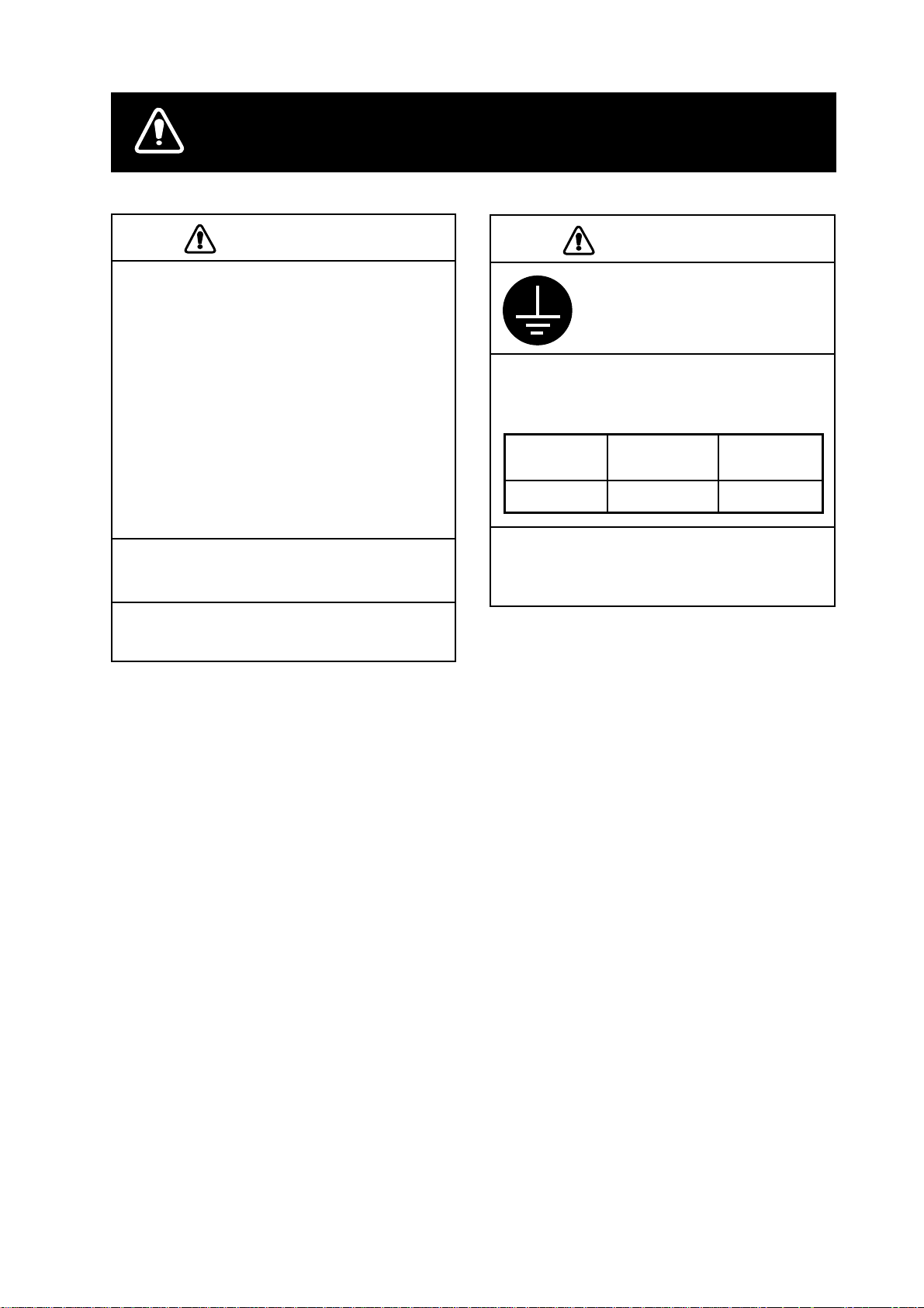
CAUTION
CAUTION
CAUTION
The mounting location should satisfy
the following conditions:
Sparate from radio transmitter, radar,
direction finder (at least 3m).
Locate the equipment away from air
conditioner vents.
Keep the equipment out of direct
sunlight.
Vibration should be minimal.
The location should be free of water
spray.
Do not install this unit on the
overhead.
Do not use the cable having a
diameter greater than 11.7 mm.
CAUTION
Ground the equipment
cable armor to prevent
mutual interference and
electrical shock.
Observe the following compass safe
distances to prevent deviation of a
magnetic compass:
Standard
compass
MD-550
Turn off the power switch at the
switchboard before beginning the
installation.
1.40 m 0.95 m
Steering
compass
i
Page 4

TABLE OF CONTENTS
System Configuration .........................................................................................................................1
Installation materials and Spare parts...............................................................................................1
Cables ...................................................................................................................................................2
Mounting............................................................................................................................................... 2
Setting................................................................................................................................................... 3
Fabrication of signal cable ................................................................................................................. 3
SPECIFICATIONS...........................................................................................................................SP-1
PACKING LIST
OUTLINE DRAWING
INTERCONNECTION DIAGRA M
SCHEMATIC DIAGRAM
ii
Page 5

System Configur a ti on
12-24 VDC
Distribute NMEA from one
input to four output
Input1
Input2
Distribute AD-10 format
Input1
Output1
Output2
Output3
Output4
Output5
Output6
Output7
Output8
Output1
Output2
Output3
Output4
Distribute NMEA from one
input to eight output
Input1
When connecting by current loop,
the standard FURUNO receive circuit
(current limiter circuit: 470 Ω,
photocoupler: PC-400/900 are
included) accepts one unit per output
line. For connection of multiple
equipment, contact a FURUNO
agent or dealer for details.
Installation materials and Spare parts
Output1
Output2
Output3
Output4
Output5
Output6
Output7
Output8
Name Type Code No. Qty Remarks
Tapping screw 4X16 SUS304 000-802-080 4 CP14-06101
Fuse FGMB 0.5A 125V 000-114-994 1 SP14-03001
1
Page 6

Cables
Mounting
Use the following cables (Japan Industrial
Standard cables) or the equivalents.
DPYC-1.5
Power cable
Armor
Sheath
φ =
11.7 mm
Conductor
S = 1.5 mm
2
φ = 1.56 mm
TTYCS-1 (Twisted pair cable)
Current loop or RS-422
Armor
Sheath
Shield
φ =
10.1 mm
Conductor
S = 0.75 mm
2
φ = 1.11 mm
TTYCS-1Q (Four core twisted)
AD-10 format
Armor
Sheath
Shield
φ =
11.3 mm
We recommend use of the following crimp-on
lug.
Conductor
S = 0.75 mm
φ = 1.11 mm
2
FV1.25-M3 (Code no.: 000-538-110)
φ = 6.6 mm
4.0 mm
φ = 3.7 mm
This unit has not power switch. If you do not
connect the MD-550 to power switchboard or
circuit breaker, install an external power switch
(local supply), locating it near the MD-550.
CR4 (POWER)
LEDs
Jumpers
216
POWER LED: Lights when the power is
supplied.
IN1 LED: Blinks when data is input.
IN2 LED: Blinks when data is input.
Note: You can confirm working of output port
(by LED) by connecting it to the other
input port. (Refer to schematic diagram.)
CR5 (IN1)
CR6 (IN2)
Jumpers
145
CR5
Input1
Output1
Output2
Output3
Output4
CR6
Input2
Output5
Output6
Output7
Output8
Connection for confirming working of output
port
2
Page 7

Setting
Factory jumper settings are for current loop
and “1 in 4 out”.
IN1 (OUT1-4) IN2 (OUT5-8)
JP4 (#1-#2),
JP5 (#1-#2),
JP6 (#1-#2)
JP4 (#2-#3),
JP5 (#2-#3),
JP6 (#2-#3)
Current loop
RS-422
JP1 (#1-#2),
JP2 (#1-#2),
JP3 (#1-#2)
JP1 (#2-#3),
JP2 (#2-#3),
JP3 (#2-#3)
JP7
1 in 4 out #1-#2
1 in 8 out #2-#3
Note1: Put short jumper into connector in
same direction as before.
Note2: Do not short jumpers JP13 & JP14. They
should be “open.”
Fabrication of signal cable
DPYC-1.5
77
3
TTYCS-1
77
Shield
Earth wire fabrication
55
1
Crimp-on lug
6
Earth wire
6
TTYCS-1Q
77
3
Armor
8
twist and cut
56
Solder
15
10
Vinyl tape
3
Sheath
6
1
Crimp-on lug
Armor
Cut the sheath.
15
10
Vinyl tape
Shield
8
Earth wire fabrication
1
55
6
Crimp-on lug
6
5
Earth wire
Armor
twist and cut
Solder
1015
Vinyl tape
3
Page 8

SPECIFICATIONS OF MULTI-DISTRIBUTOR
MD-550
This equipment is used for distribution of navaid data from navigation equipment. It provides four
outputs each from two independent inputs or eight outputs from one input by changing an
internal setting. AD-10 format signal is also available to distribute four outputs from one input.
1. Port Input: 2 ports (data / shift lines)
Output: 8 ports (4 output for one input)
2. Type of Signal Serial Signal
Input: IEC 61162-1 or NMEA 0183 Ver. 1.5/2.0
(RS-422 or current loop)
Output: IEC 61162-1 (RS-422)
3. Transmission Rate 4800 bps to 38400 bps
4. Power Supply 12-24 VDC: 0.25-0.15 A
5. Coating Color 2.5G7/2 Newtone No.5
SP-1 E4408S01B
Page 9

Page 10

Page 11

Page 12

 Loading...