

Page 1
Operator’s Guide to
Marine Radar
Page 2
Table of Contents
© Copyright Furuno USA 2008
All Rights Reserved
1-3) Principles of Radar
3-5) Radar System Congurations
5-6) Radar Terminology
6-8) Radar Controls
9) Targeting Birds
10-11) Range, Bearing and Position
12-14) Advanced Radar Operation
15-18) Radar FAQ's
19) Additional Resources
20) Radar Mark Denitions
21) Maintenance
Boats of all types can benet from having a Radar
onboard for navigation and situational awareness..
When it comes to safety on the water, no other piece of
electronic equipment on your bridge is as important
as your Radar. For more than 30 years, Furuno Radars
have consistently won the prestigious NMEA (National Marine Electronics Association) award for Best Radar. Whether you are looking for a compact 2.2kW unit
or a commercial grade 50kW Radar, Furuno is the single largest source of Radars you can rely on. This book
will help you learn about what a Radar is, how it works,
and how to get the most from what is perhaps the most
important navigation device you will ever own.
Page 3

1. Principles of Radar
What is Radar?
Radar is an acronym meaning RAdio Detecting And
Ranging. It is a device which measures not only the
time it takes for a pulsed signal to be reected back
from an object but also its bearing relative to your
position. No other piece of marine electronics can give
you as much information about objects around your
own ship as Radar.
Present state of Radar:
Radar was developed during World War II. Today,
Radar is available for all classes of vessels including
small shing vessels and pleasure craft. Many
pleasure boats may also have a color video sounder
(Fish Finder) or navigation device such as a GPS
receiver, but the single most important piece of
electronics is the Radar. No other gear can give you
the ability to spot a vessel coming at you out of the
fog, or tell you the location of the inlet to a harbor in
the pitch black of night.
For navigational safety, nothing beats Radar. While
your chart plotter may show you where everything
around you is supposed to be, only your Radar can
show you where everything is, including coastline
and navigation aids such as beacons or buoys, as well
as uncharted objects such as vessel trafc and other
obstructions.
About Furuno Radars:
The National Marine Electronics Association (NMEA)
annually recognizes its member marine electronics
manufacturers for superior products. Furuno annually
takes home the top award in several categories of
marine electronics equipment, and our Radars have
won the top prize every year since 1976. Furuno
has repeatedly won the coveted NMEA award for
Manufacturer of the Year - Support. These awards
make it clear that Furuno is the leading manufacturer
of Radar in terms of quality, reliability and after-
purchase support.
What Radar Can Do
Radar mainly functions as an anti-collision aid. It
also provides information about the whereabouts of
neighboring vessels, coastal outlines, etc.
Navigate in darkness and fog•
In fog or darkness, you may lose situational awareness
around your own ship because of poor or no visibility.
With Radar acting as your eyes, however, you have
the ability to monitor other ships’ movement under
these conditions.
Collision avoidance•
The guard alarm feature of every Furuno Radar alerts
you when targets enter a particular area, or own ship is
nearing a danger area. The alarm area can be forward
of own ship or a 360-degree circle around the vessel.
When Radar targets such as other ships, landmasses or
buoys enter the zone, an audible alarm sounds to alert
the operator.
Assess target movement•
The Echo Trail feature simulates target movement
in afterglow. It is useful for assessing the movement
of all targets relative to own ship. Some Radars have
the capability to show the true movement of targets,
providing increased navigational safety.
Determine own ships position•
Since Radar sees further than the naked eye, the
echoes from islands and landmasses can be used to
determine own ships’ position. When running near
land, you can use peninsulas and other targets whose
echoes show distinct contours on the display to
determine own ships’ position. Distant, tall mountains
or bridges may be similarly used provided they are
above the horizon
Navigatetospeciclocation•
Fishing vessels and pleasure boats use Radar to
help them navigate to favorite shing spots. When
navigating to a shing spot, the forces of wind
and current can combine to throw the vessel off its
intended course. To remember your location if your
ship drifts, use the VRM and EBL to mark range and
bearing to nearby islands or peninsulas.
120
Page 4
Navigate straight to waypoint•
The map-like picture displayed by Radar helps you
navigate straight to a waypoint and compliments chart
plotter images.
Receive Radar beacon (RACON)•
Radar can receive pulsed signals from a Radar beacon
to determine own ships position.
Fishing operation•
Besides its basic function as an aid to navigation,
Radar is also a valuable tool for shing operations.
Purse seiners use it to monitor net shape, observing
the echoes from oats attached to the net. It is
especially useful in eet shing for determining
position of vessels, locating shing grounds and
positioning vessels.
Specialty sherman use Radar to search for sea birds,
which may be an indication of the presence of bait
sh or their target species. This technique has become
easier with the advent of dual-range simultaneous
scanning, such as that found in NavNet 3D, where
the navigator can use one Radar screen with the gain
set for targeting birds, while the other Radar screen
is used to navigate. As you can see, for many shing
vessels Radar functions more often as an aid to shing
rather than an aid to navigation.
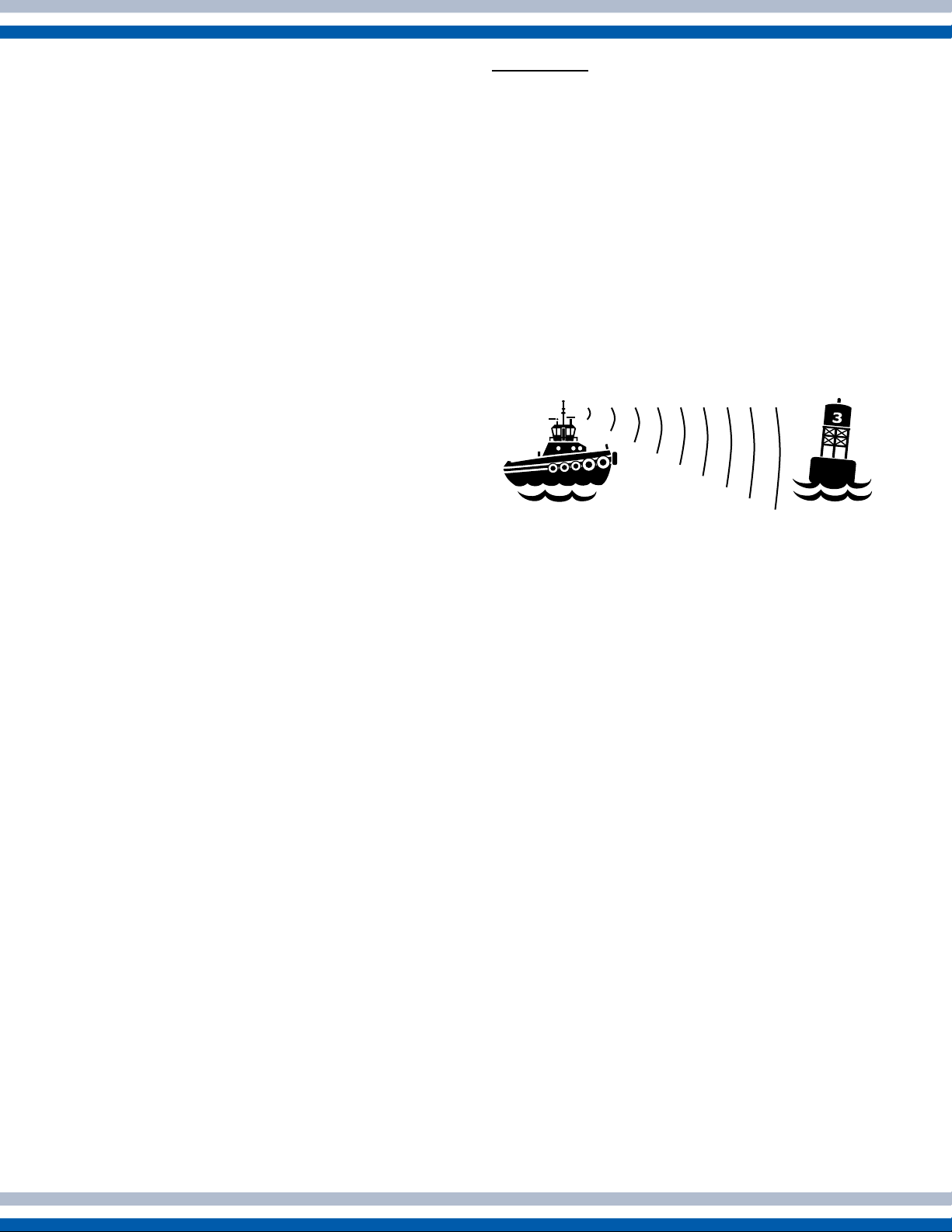
How It Works
Did you ever shout at a cliff and hear the echo of your
shout? Radar works in a similar manner. Imagine that
radio pulses are emitted from the scanner in a certain
direction. When the pulse strikes an object such as
a ship or island some of the energy returns to the
scanner. The direction in which the scanner is pointing
when the reection is received is the direction of the
target causing the reection. Since radio waves travel
at a near-constant speed, the time required for the
reected echo to return to the scanner is a measure of
the range to the target.
How Radar determines range
The radio pulse makes a complete round trip, but
only half the time of travel is needed to determine the
range to the target. This equation shows how range is
determined:
2
D = 1/2 x cT
c = Speed of Radio Pulse (3 x 10⁸ m/sec)
T = Time between transmission of radio pulse and
reception of reected echo
D = Distance
Both radio waves and light travel at the near-constant
speed of 186,000 miles per second; therefore, the
Radar can process vast amounts of information in
a very short time. Comparatively, Sonar and Fish
Finders use ultrasonic waves rather than radio waves.
Since the propagation speed of the ultrasonic wave
is 1,500 miles per second, signal processing is much
slower with these devices than with Radar.
How Radar determines bearing
Radar determines the range to a target by measuring
the amount of time required for a reected echo to
return to the scanner. Bearing to a target is determined
by the direction from which a reected echo returns.
The scanner rotates 360 degrees about its vertical
axis, using a special gear. In order to achieve precise
bearing resolution the antenna radiates RF (radio
frequency) power in the form of a highly directional
beam. “Super” beams having horizontal beamwidth
on the order of one 1 degree or less provide highly
precise bearing information. The sharper the beam,
the more accurately the bearing of a target can be
determined.
How the Radar displays targets
Radar targets are displayed on what is called a Plan
Position Indicator, or PPI. This display is essentially
a polar diagram, with the transmitting ships’ position
at the center. Images of target echoes are received
and displayed at their relative bearing, and at their
distances from the PPI center. Early model Radars
displayed targets and possess few features such as
heading marks and range rings. To view the display,
a viewing hood was required to block out extraneous
light.
Page 5
Almost all late model Radars use Liquid Crystal
Display (LCD) or daylight bright Cathode Ray
Tube (CRT) displays. These types of displays
provide steady, bright, non-fading Radar echoes
in monochrome or color depending on model.
The picture is visible even in full daylight. Digital
information is displayed on-screen to keep you
informed of your navigational situation at all times.
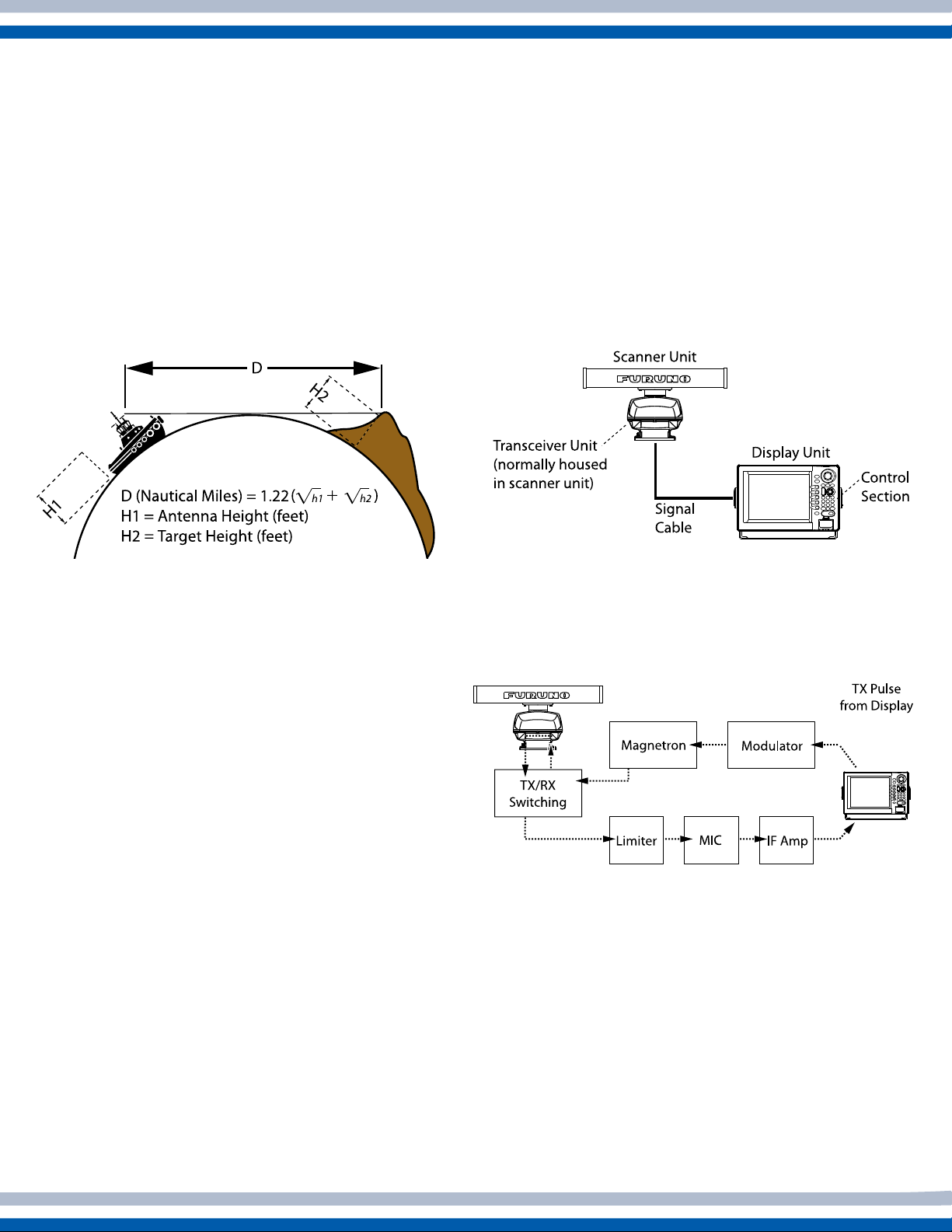
Radar range
Atmospheric conditions and target shape, material and
aspect slightly affect Radar range. However, Radar
range is generally calculated as follows:
RadarSystemConguration
Basic system
The basic Radar system consists of two units: the
scanner unit and the display unit. The transceiver
(transmitter/receiver unit, or t/r) is generally housed
in the gearbox of the scanner unit. In some designs
the t/r is separate from the scanner unit and contained
in its own housing; such a unit is referred to as ‘t/r
down.’ Also, the control unit may be separate from
the display unit so as to allow for custom selection of
display in what is referred to as a ‘black box’ system.
Figure 1 - Determining Radar range
D is the distance from the scanner to the target
horizon. Under normal atmospheric conditions, this
distance is 6% greater than the optical horizon. This
is because radio waves bend or refract slightly by
atmospheric change.
The higher the scanner or target is above the surface,
the longer the detection range. For example, if the
scanner is 9 meters above the sea surface and the
height of the target is 16 meters, you should be able to
see the target’s echo on the display when the target is
15 miles from the Radar.
Unusual propagation conditions
Air ducts created by atmospheric conditions can affect
radio pulse propagation and thus Radar range. When
the radio pulse is bent downward, radio pulses can
travel great distances thereby increasing the ranges
at which targets can be detected. This is called super-
refraction. The opposite condition, in which Radar
waves bend upward and decrease the range at which
targets can be detected, is called sub-refraction.
Figure 2 - Basic Radar system
Scanner unit components
Most scanner units employ the circuits and devices
shown in Figure 3:
Figure 3 - Circuits and devices of a scanner unit
Magnetron
The magnetron generates the radio pulses.
Magnetrons, as well as the Radar itself, are classied
by their transmitting frequency band. There are two
main frequency bands in commercial Radar: X-Band
(9,000 MHz band; wavelength 3cm) and S-Band
(3,000 MHz band; wavelength 10 cm). Magnetron
output power ranges from 1kW for small Radars to
60kW for large Radars. Table 1 compares the S-Band
and X-Band frequencies.
Page 6
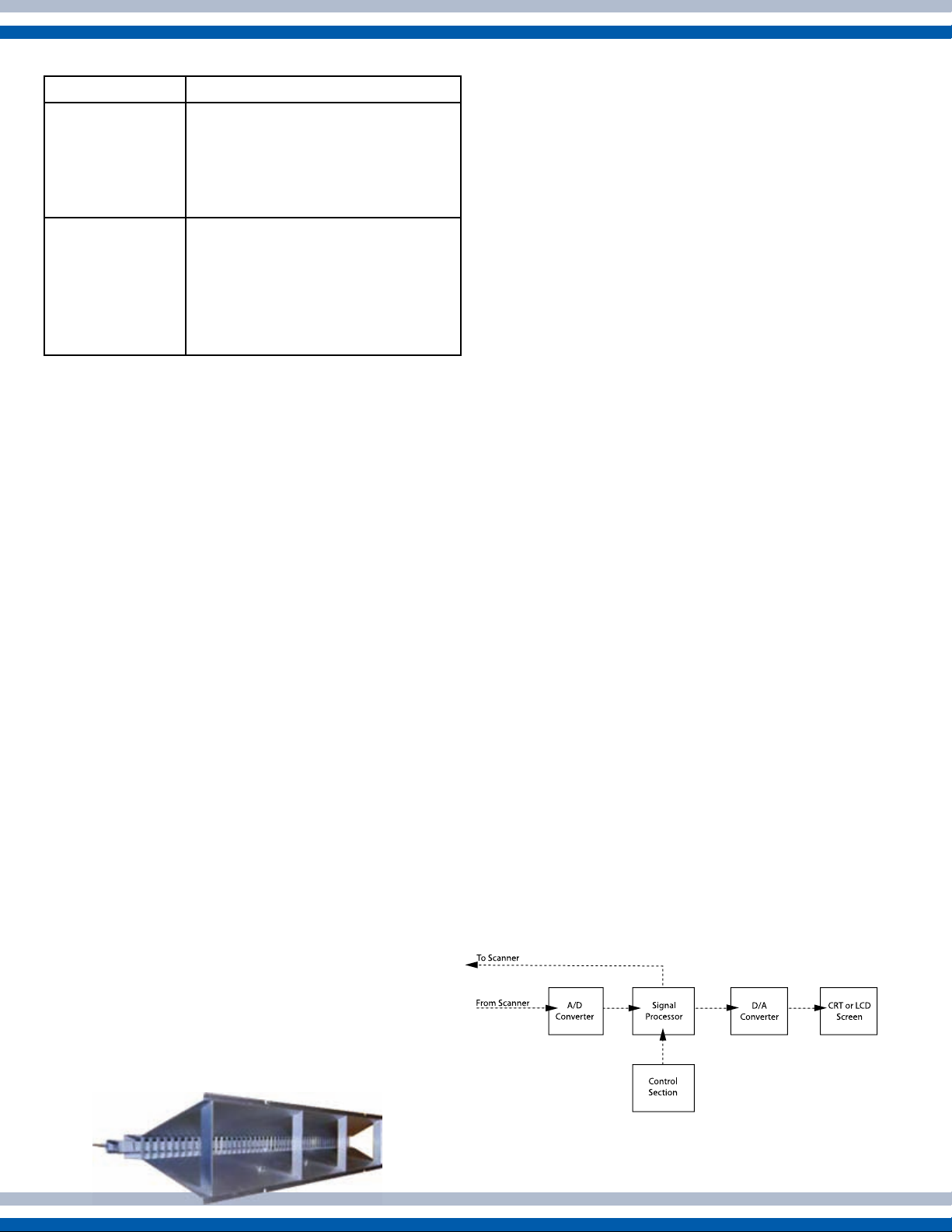
Table 1 - Comparison of X-Band and S-Band
Frequency Band Characteristics
X-Band
S-Band
Short wavelength for better •
directivity
Attenuation in precipitation is •
greater than on S-Band
Small, light-weight antennas•
Longer wavelength for long •
range detection
Penetrates precipitation for •
excellent performance in
inclement weather
Large antenna•
Modulator
The device responsible for monitoring the magnetron
for proper operation is the modulator. It ensures that
the magnetron transmits at exactly the same frequency
throughout the duration of the pulse, and that the time
between pulses is the proper length.
TX/RX Switching
A TX/RX switching device enables the Radar to
transmit the radio pulse and receive its reected echo
through one scanner. The switching device used by the
Radar is called a circulator It consists of a permanent
magnet and a ferrite core. When transmitting, it
directs radio pulses to the scanner and disconnects
the receiver circuits. When receiving, it funnels weak
reected echoes away from the magnetron to prevent
both ow to the magnetron and loss of receive signal.
The length of the array affects horizontal beamwidth,
and thus the Radar’s ability to determine target
bearing. The longer the array, the more accurately the
Radar can determine bearing. For example, an array
of 50 cm length gives a horizontal beamwidth of 5
degrees, while one of 300 cm length gives a horizontal
beamwidth of 0.75 degrees.
Scanner directivity is a measure of the two
beamwidths. One is in the horizontal plane, known as
horizontal beamwidth, and the other is in the vertical
plane, known as vertical beamwidth. The narrower
the horizontal beamwidth the sharper the beam. The
vertical beamwidth should be wide; it is typically 20
to 25 degrees. The main reason for a wide vertical
beamwidth is to ensure the ability to display a target
while own ship is pitching and rolling.
Limiter
The limiter protects the receiver circuits from damage
in the event own ship’s Radar receives radio pulses
from another ship’s Radar. When this occurs, the
limiter attenuates them to protect the next stage MIC
(Microwave Integrated Circuit).
MIC
MIC is an acronym meaning Microwave Integrated
Circuit. The MIC consists of a local oscillator and
mixer circuits. Incorporating those devices on an IC
improves quality, reliability, sensitivity and noise
gure (nf).
Scanner
The scanner transmits the radio pulses and receives
their reected echoes. Most scanners rotate at a
constant speed of 24 rpm. Many modern Furuno
Radar scanners rotate at variable speeds dependent
upon the range in use in order to optimize Radar
detection. The type of scanner used by most vessels
is the slotted array, an antenna with a series of slits
spaced at suitable intervals and angles from which
radio pulses are transmitted. The reected echoes also
pass through these slits.
Figure 4 - A typical slotted array scanner
IFAmplier
The IF amplier amplies the Intermediate Frequency
signal output by the MIC.
Display unit components
Most display units employ the devices shown in
Figure 5:
Figure 5 - Devices of a display unit
4 17
Page 7
A/D Converter
The received IF signal is an analog signal. This signal
is converted to a digital signal in order to undergo
various processing in the display unit. The A/D
(Analog to Digital) converter converts analog signals
to digital signals.
Signal Processing
This section is the heart of the Radar and contains
computers, memories, and other IC’s. Extensive use of
digital techniques permits high speed processing.
Control Unit
The control unit contains various keys and controls for
adjustment of the Radar picture. Whenever a control
setting is changed the associated reaction appears
almost immediately on the display. In some Radar
designs, the control unit is separate from the display
unit.
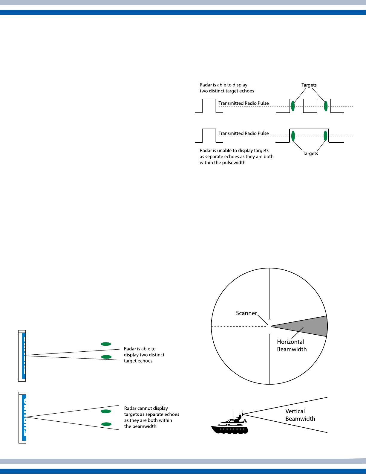
Range resolution is a measure of the capability of the
Radar to display as separate pips the echoes received
from two targets that are on the same bearing and
are close together. The main factor that affects range
resolution is pulselength. A short pulselength gives
better range resolution than a long pulselength.
Figure 7 - Example of range resolution
Basic Radar Terms
Radar Resolution: Different than display
resolution, which is a measure of the pixels in an LCD
display, Radar resolution describes the Radar’s ability
to distinctly display two Radar targets which are
close to each other. Radar has two types of resolution:
range, and bearing.
Bearing resolution is a measure of the capability of
the Radar to display as separate targets the echoes
received from two targets that are at the same range
and close together. The principal factor affecting
bearing resolution is horizontal beamwidth. The
narrower the horizontal beamwidth the better the
bearing resolution.
Generally, use a short pulselength on short ranges for
better range resolution, and a long pulselength on long
ranges for longer range detection.
Beamwidth: Beamwidth is the angular width,
horizontal or vertical, of the path taken by the Radar
pulse. Horizontal beamwidth ranges from 0.75 to
5 degrees, and vertical beamwidth from 20 to 25
degrees.
Figure 6 - Example of
bearing resolution
Figure 8 - Example of
scanner beamwidth
Page 8

Pulse Repetition Rate: Pulse repetition rate is
the number of radio pulses transmitted in one second.
It is automatically determined by pulselength and
detecting range. For short ranges, pulselength is short
and the pulse repetition rate is high. For long ranges,
pulselength is long and the pulse repetition rate is low.
Minimum detectable range: This is the
minimum range at which a target is detectable by the
Radar. It is determined by scanner height, vertical
beamwidth, blind sector within the scanner beam, and
pulselength.
Maximum detectable range and output
power:
Radar raises the maximum detectable range by only
19 percent. In the reverse case, halving the output
power lowers the maximum detectable range by
16 percent. While you can increase the maximum
detectable range by using a high output power Radar,
a better (and more economical) way to do it would
be to mount the scanner as high as possible above the
waterline and/or utilize a longer antenna to increase
horizontal beamwidth.
Doubling the output power of a typical
Control Description:
Power: Powers the entire Radar system. After
turning on the power, a timer displays the time
remaining for transmission preparation. “ST-BY”
appears when the Radar is ready to transmit. The
method of turning off the power varies by model;
consult your Operator’s Manual for details on
powering off your Radar.
Economy: The economy mode turns off power to
the display in stand-by to lessen power consumption.
Trackball/Cursor Pad: The trackball or cursor
pad shifts the cursor, which sets the guard zone,
displays range and bearing to a target, etc. Some
models may have individual arrow keys in place of a
trackball or cursor pad.
Scanner: This switch starts and stops scanner
rotation. Turning the switch off when transmitting
sets the Radar in stand-by. A rotating scanner can be
dangerous - before turning the switch on, be sure no
one is standing near the scanner unit.
2. RADAR CONTROLS
This section briey describes the function, objective
and usage of Radar controls. Note that some controls
described here may not be provided on your Radar.
For detailed control description, refer to your
Operator’s Manual.
Precautions:
A rotating scanner is dangerous. Before turning the
Radar on, be sure no one is near the scanner unit.
The scanner unit emits high frequency radio pulses,
which can be harmful, particularly to your eyes. Never
look directly into the scanner unit when the Radar is
in operation.
Key response: The Radar normally releases a
beep when you correctly enter a command. If no beep
is released, try again. Incorrect command generates
several beeps. This function can usually be disabled,
but caution must be used as this audible feedback is
important to verify correct entry of commands.
ST BY/TX: Press this key to transmit radio pulses.
To stop transmitting, press the key again.
Gain: This control adjusts receiver sensitivity. Adjust
the gain to increase sensitivity and display echoes. For
long range, adjust the control so background noise
is just visible on the display. For short range, some
Radar operators set this control relatively high and
adjust sensitivity using the A/C SEA control.
A/C Rain (FTC): The Rain control, also called FTC
(Fast Time Constant), suppresses the reected echoes
from rain, hail and snow to clear the display. On the
X band Radar, because of its short pulselength, the
echoes from legitimate contacts can become lost in the
echoes from precipitation, called rain clutter. When
rain clutter masks the display, adjust this control to
break up the clutter and distinguish echoes. Adjust the
control so that the clutter just disappears; too much
A/C Rain action may shrink or erase the echoes from
legitimate targets.
6 15
Page 9

A/C Sea (STC): Sea control, also called STC
(Sensitivity Time Constant), suppresses reections
from waves near own ship. In rough seas the
reected echoes from wave crests are very strong,
producing a mass of echoes which cover the central
part of the display. This is called sea clutter. Any
echoes within the clutter will be partially or totally
obscured. Adjust this control to reduce the clutter
and distinguish echoes. The proper setting should be
such that the clutter is suppressed and echoes become
distinguishable. If the control is set too high, both sea
clutter and echoes will disappear from the display.
When there is no sea clutter visible on the display,
turn the control fully counterclockwise.
Brill: This control adjusts the display brilliance.
Range: Press the [+] and [-] keys to raise and lower
the range respectively. When you change ranges,
the number of range rings and range ring interval as
well as pulselength are automatically changed. For
conrmation, the range and range ring interval appear
on the display.
Rings: Press this key to show or hide the range
rings. Range rings provide an estimate of the range
to a target. The number of range rings and range ring
interval automatically change with the range. Ring
interval (distance between rings) appears on the
display.
VRM: The VRM (Variable Range Marker) measures
the range to targets. To measure range, press the key
to display the VRM. It appears as a dashed circle.
Adjust the VRM so that it touches the inner edge of
the target. The range to the target appears in a data
box on the display. Some Radars may display two
VRM’s; the length of the dash of the #2 VRM is
longer than that of the #1 VRM.
EBL: The EBL (Electronic Bearing Line) measures
bearing to targets in degrees. To measure bearing,
press the key to display the EBL. It appears as a
dashed line. Adjust the EBL so that it bisects the
target. The bearing to target appears in a data box on
the display. Some Radars can display two EBL’s; the
length of the dash of the #2 EBL is longer than that of
the #1 EBL.
Offset EBL: This EBL can be shifted to any
location on the display. This allows you to predict
other ships’ course (to avoid collision) and measure
the range and bearing between two targets.
Plot: This function plots the movement of all ships
relative to own position. Press the key to start plotting.
The positions of all targets at the end of the preset
time are marked on the display.
Echo Trails: This feature continuously shows the
movements of other ships in afterglow. It is useful for
assessing target movement and collision possibility.
Display Mode: The display mode determines target
position and movement on the display. There are two
types of display mode: Relative and True.
Relative Bearing Display:• This mode is also
known as Head-up, since own ships heading is
always at the top of the display. The position of
own ship is xed and echoes of all other objects
therefore move relative to own ship. This is the
usual form in small Radar sets.
True Bearing Display:• This mode is sometimes
called North-up since the display is oriented
North. This mode is suitable for long -range
observation since it is somewhat like looking at a
nautical chart.
Off Center: This key shifts the display center
to location desired. The off-center display allows
the operator to view the situation around own ship
without changing the range. Set the cursor where you
want the center position to be, and then press the key.
To cancel the off-center display, press the key again.
X2 Zoom: The X2 ZOOM feature allows you to
take a closer look at a target of interest. Set the cursor
near the object you want to zoom and press the key.
To cancel zoom, press the key again.
Index Lines: Index lines are useful for maintaining
a constant distance between own ship and the
coastline or a partner ship. Press the key to toggle
index lines on and off.
Page 10

Interference Rejection: This control reduces or
eliminates interference received from another ship’s
Radar. Turn it off when no Radar interference exists.
Guard Alarm: The guard alarm creates a zone
about own ship, either complete 360 degree zone or
a specic area forward of own ship. If targets enter
or exit the zone an audible alarm sounds to alert the
operator.
Echo Averaging: The Radar’s internal circuitry
processes echo data to obtain a desired effect. The
result depends on the Radar model. For example,
some Radars may suppress brilliance of unstable
echoes (sea clutter, etc.), or emphasize an unstable
small echo.
Huer, Color, Background Color: These
settings change display color and background color
respectively to improve display visibility. Note that
marks and characters also change color when the keys
are pressed.
HM Off: The heading mark may sometimes hide a
small echo. To show that echo, press and hold down
the HM OFF key to temporarily erase the heading
mark . Release the key to display the heading mark.
Echo Stretch: This function ‘stretches’ small
echoes to make them easier to see. It stretches not
only small echoes but also returns from sea and
rain clutter and Radar interference. For this reason,
make sure clutter and interference are sufciently
suppressed before using echo stretch.
NAV: This key shows/hides navigation data,
including position, range and bearing to waypoint,
ship’s speed and more. This feature usually requires a
navigation aid which can output data in NMEA0183
or NMEA2000 format. If a gyrocompass is connected
to the Radar, a dashed line connects navaid-selected
waypoint with own ship’s position.
Figure 9 shows a sample Radar display. Own ship’s position is at the display center. The Radar range is 12
nautical miles and the range ring interval is 2 nautical miles. The circled objects are ARPA targets and the
triangle objects are AIS targets. The large, continuous echoes are from land masses. Note that the actual shape
of a target cannot be displayed on the Radar - only the portions struck by the radio pulse appear on the display.
8 13
Page 11

Targeting Birds With Your Furuno Radar
It’s a well known fact that if you
want to catch fish you need to know
how to find them, and in order to
find the fish, you need to locate
the birds - the undisputed masters
of fish finding technology. What
is less clear is exactly how to go
about targeting birds with Radar, a
tool normally reserved for collision
avoidance. This section will remove
some of the mystery surrounding the
subject.
The first thing to think of when
considering bird-tracking Radar is
antenna beamwidth. Remember
that the narrower the beamwidth,
the greater target discrimination
you will have. For this reason,
dome antennas are not as adept
at tracking birds as a comparable
open array antenna. As the length of
the antenna radiator increases,
beamwidth becomes narrower, so
a larger antenna will invariably offer
better target discrimination.
Experience and practice will make
you a bird-finding machine, but to
get there you need to start with the
basics. For the novice, it is best to
practice these techniques on a clear
day with calm seas. It is easiest to
first visually locate a flock of birds
that you want to target.
To target the birds, set the Radar to
a mid- or long-range. Next, increase
the Gain control until you see noise
on the display. This will appear as
a blanket of small specks. You will
need to leave the Gain turned all
the way up, thus setting the receiver
These birds were targeted using the Furuno 1954C
NavNet Radar. True Color is highly desirable when
targeting birds, as demonstrated above; these flocks were
easily picked out in red against the blanket of clutter.
for maximum sensitivity in order to
detect birds. Resist the temptation
to turn up the AC/Sea or AC/Rain to
drop out the noise. Flocks of birds
may look like dense, recurring noise
rather than a solid target, but you
should be able to see them clearly.
This is what you will be looking for
when you don’t have a visual cue as
to where the birds are feeding.
If your Radar is capable of operating
in True Motion, do so. You will be
Practice these techniques and soon
you will be scouting your fishing
spots just like the pros.
stabilizing the
display, and you
will be able to
tell if the flock
is travelling in
a straight line
looking for bait
pods or if they
have found their
target school and
are feeding.
When operating
in Head Up or
True Motion, be
sure to turn on
your target trail
function and set
it for long trails
to help track
travelling flocks.
Radar Factoids - UHD Digital Radar
Radar Factoids - UHD Digital Radar
Furuno’s NavNet 3D integrates Ultra High Denition
(UHD) Digital Radar that facilitates fully automatic,
high-precision Gain, Sea/Rain Clutter and Tuning
control that allow the auto mode to adapt to a variety
of sea-states for hands-free operation and ultimate
performance.
One amazing features of Furuno UHD Digital Radar
is ‘Real Time’ dual range Radar display. NavNet 3D
simultaneous scanning technology allows dual
progressive scan to display and update two Radar
pictures, both long and short range, at the same
time as opposed to the alternating update methods
of typical conventional dual range Radars. This
can be used to have one screen with the gain set
to locate birds and buoys, while you use the other
Radar screen to navigate.
UHD™ oers crystal clear, noise-free target presentation with
automatic real-time digital signal processing. Antenna rotation
speed (24 /36/48 rpm) is automatically shifted to the appropriate
pulse length.
9
Page 12

Radar Picture and Marks
The Radar display shows you not only echoes but also
marks and information. This section describes the Radar
picture and marks you will see on the display.
Measuring Range
The range from own ship to target can be measured in three
ways: by range rings, by cursor, and by VRM.
By Range Rings:
The RINGS key shows/hides the range rings and adjusts
their brilliance. To measure range by the range rings, count
the number of rings between the center of the display and
the echo. Check the range ring interval at the top of the
display and judge the distance of the echo from the inner
edge of the nearest ring.
By EBL:
Display an EBL and adjust it so that it bisects the
target. The bearing to the target appears on the
EBL readout. Bearing relative to heading is relative
bearing, while bearing relative to North is true
bearing.
Figure 11: Comparison of true and relative bearing
By Cursor:
The cursor provides a more accurate measurement of range
to targets. Set the cursor intersection on the inner edge of
the target. The range from own ship to target appears on the
display.
By VRM:
The VRM, like the cursor, provides a more accurate
measurement of the range to targets. Display a VRM and
adjust it so that it rests on the inner edge of the target. The
range to target appears on the VRM readout.
Figure 10 - How to measure range
Measuring Bearing
The relative bearing from own ship to targets can be
measured by the cursor and by the EBL. With gyrocompass
connection, you can display true bearing.
No Gyrocompass Connection:
You can determine true bearing by adding relative
bearing to your compass reading. If the sum is over
360 degrees, subtract 360 from the number.
Gyrocompass connection:
Select the true bearing display, north-up mode.
Measure the bearing by the EBL and check the EBL
readout.
AIS provides real-time information about AIS-equipped vessels on your
AIS-ready chart plotter, navigation software or Radar. This information is
presented graphically, allowing you to monitor and avoid AIS equipped ves-
sels in the area. Since AIS targets can be received even if they are not within
line of sight, the system greatly enhances situational awareness in congested
waterways, limited visibility or heavy sea conditions, and gives the navigator much
more information about AIS equipped vessels. Some common AIS symbols are:
By Cursor:
Set the cursor intersection on the center of the echo. The
bearing from own ship to target appears on the display.
10 11
Page 13

How to Suppress Sea Clutter
How to Suppress Rain Clutter
The effect of echoes with waves changes with wave
size, sea conditions, weather and antenna height above
the sea surface. Sea clutter can be suppressed by not
only the A/C SEA controls but also by a combination
of A/C RAIN and GAIN controls.
General Procedure:
Turn the A/C SEA control fully counterclockwise
(down). Turn the GAIN control fully clockwise (up).
Slowly turn the GAIN control counterclockwise
(down) to reduce sea clutter and distinguish targets.
Note that echoes that are weaker than the sea clutter
will not appear.
If this action does not remove sea clutter near own
ship, gradually turn the A/C SEA control clockwise
(up) to reduce sea clutter.
NOTE: The A/C RAIN control is also effective in
suppressing sea clutter. It is most effective when the
echo of the target is larger than that of the sea clutter.
Its main advantage over the A/C SEA control is that,
when used to suppress sea clutter, it does not shrink
small echoes.
Echoes from precipitation cover a much wider area on
the display than echoes from waves. However, since
they are not as strong as those from waves, they can
be suppressed by adjusting the A/C RAIN and GAIN
controls.
Example 1: Drizzle over a wide area
If using the A/C RAIN control shrinks or erases
echoes, turn the GAIN control clockwise (up) until
rain clutter just appears on the display.
Example 2: Density of rain different from area to
area
In this instance you usually reduce the clutter in the
area of light rain by adjusting the A/C RAIN control.
Be careful not to remove the clutter completely;
weak echoes may be missed. If strong clutter appears
in the area of heavy rain, turn the GAIN control
counterclockwise (down) a little.
An ARPA target is measured by range and bearing from
own ship and located on the Radar PPI. When ARPA
and AIS are combined and their symbols are within an
operator-set criteria, the ARPA symbol is merged with the
AIS symbol. Some common ARPA symbols are:
Page 14

3. INTERPRETING THE DISPLAY
This section provides the information necessary for
interpreting the display.
Radar Picture and Target Properties
The strength of the reected echo depends not only
on the height and size of the target, but also its shape,
material composition and angle at which the radio
pulse strikes. The size of the target actually has little
to do with the reected echo. If the radio pulse strikes
it at a right angle, even a small target will return
a strong echo provided that the material is a good
reector of RF energy.
A return echo will be weak if the angle at which the
radio wave strikes a target is small. For example,
at surfaces such as sandy beaches, sandbars and
mudbanks have almost no area that can reect
energy back to the Radar. Conical surfaces, such as
lighthouses, generate weak return echoes because their
shape diffuses most of the radiated energy. Because of
their poor reecting properties, at or conical surfaces
do not return an echo suitable for range determination.
Radar sees only the near side of targets. For example,
it cannot show you what is behind a sea wall or an
island. The echo of a mountain peak may appear on
the Radar display as a peninsula or small island. The
Radar image is not always as it seems - you should
always exercise caution when interpreting the display.
Targetmaterialandreectedecho
Generally, steel objects return a very strong echo
while reefs and water return weak echoes. The
weakest echoes come from wood and berglass
objects. In summary, non-metallic objects or those
that are at or conical in shape do not make good
Radar targets, and the Radar may display only weak,
intermittent echoes - or it may not display them at all.
Precipitation
Rain, snow and hail may return echoes which appear
on the display as a blurred or cluttered area. You can
suppress them by adjusting the A/C RAIN control, or
lowering the sensitivity.
InuenceofWavesandPrecipitation
On short range, a mass of echoes covers the central
part of the display. This is caused by echoes from
waves, called sea clutter. The higher the waves the
more extensive the sea clutter on the display. In most
cases it is more pronounced to the windward side of
the vessel. To suppress sea clutter, use the A/C SEA
control. Always leave a little sea clutter on the display
to be sure weak target echoes are not erased.
ARPA and AIS
ARPA is an acronym that stands for Automatic Radar
Plotting Aid. The ARPA functions as a collision
avoidance tool, tracking individual Radar targets and
plotting their course and speed in order to determine
the closest point of approach (CPA) and time to
closest point of approach (TCPA) to own vessel. Data
such as course, speed, range, bearing, CPA and TCPA
can be called up in a data box on the screen simply by
selecting the target of interest.
AIS is an acronym that stands for Automatic
Identication System. The AIS system is used to
exchange vessel and navigation data including vessel
name and call sign, length and beam, position with
accuracy indication and integrity status, course, speed,
heading and ROT and other specic information, all
in real time. Data is shared with other nearby ships as
well as coastal VTS (Vessel Trafc Service) stations.
Unlike ARPA, which is dependent upon Radar returns
to track targets, AIS targets are acquired and tracked
via VHF (radio) signal. This means that AIS-equipped
targets that are partially or totally obscured from the
sweep of the Radar can still be acquired and tracked if
within VHF coverage.
12
Page 15

Other Aids To Navigation
False Echoes
The Radar display sometimes shows a series of
dots or dashed radial lines. They are navigational
marks transmitted by Radar beacons. A Radar
beacon transmits a coded signal when it receives a
radio pulse from a Radar, and some Radar beacons
transmit continuously. Its main purpose is to help the
navigator nd his own position in terms of range and
bearing from the beacon. There are two main classes
of Radar beacons: RACON and RAMARK. Another
type of Radar beacon is called a Search And Rescue
Transponder, or SART. When activated by a crew
member on a ship in distress it transmits a distinctive
signal when its transmitter is triggered by a radio
pulse.
RACON
The RACON (RAdar beaCON) automatically
transmits a signal when it receives a radio pulse.
The signal transmitted by the RACON appears
intermittently on the display as a Morse character, a
dashed or dotted line radiating out from the beacon.
In the U.S., RACONs are used to mark lighthouses
and buoys, inconspicuous coastlines, navigable
spans under bridges, offshore structures such as oil
platforms, or environmentally sensitive areas such as
coral reefs.
Occasionally false echoes appear on the screen at
positions where there is no target. In some cases the
effects can be reduced or eliminated. The operator
should become familiar with the appearance of these
false echoes so as not to confuse them with echoes
from legitimate contacts.
Indirect echoes
Indirect echoes may be returned from either a passing
ship or from a reecting surface on your own ship,
such as a stack. Figure 12 illustrates the effects of an
indirect echo. Indirect echoes may be recognized as
follows:
They usually occur in shadow sectors•
They appear on the bearing of the obstruction but •
at the range of the legitimate contact
When plotted, their movements are usually •
abnormal
Their shapes may indicate that they are not direct •
echoes
RAMARK (Radar Marker)
The RAMARK is a Radar beacon which transmits
either continuously or at intervals. When a Radar
scanner faces a RAMARK it receives the RAMARK
signal. The RAMARK signal appears on the display
as a Morse character, a dashed or dotted radial line.
RAMARKs are not commonly used in the U.S.
SART (Search And Rescue Transponder)
When a Radar transponder is activated by a ship in
distress, its transmitter emits a signal when activated
by a radio pulse. The appearance of the signal on the
display depends on the distance between the Radar
and the transponder. The closest transponder signal to
own ship position is the approximate position of the
ship in distress.
In the GMDSS (Global Maritime Distress and Safety
System), certain classes of vessel must carry a SART.
You should continuously monitor the display for
Radar transponder signals. Be prepared to offer
assistance to a ship in distress if required.
Figure 12 - Example of Indirect Echo
Page 16

Multiple Echoes
Multiple echoes can occur when a strong, short-range
echo is received from a target. A second, third or more
target may be observed on the display at double, triple
or other of the actual range of the target. Multiple
reection echoes may be reduced or often eliminated
by decreasing the sensitivity.
Blind and Shadow Sectors
Funnels, stacks, masts or derricks in the path of the
antenna may hide Radar targets which are behind
them. If the angle subtended at the scanner is more
than a few degrees a blind sector may be produced.
Within the blind sector small targets at close range
may not be detected while larger targets at much
greater range may be detected.
Side Lobe Echoes
Every time the scanner rotates, some radiation escapes
from each side of the beam. This energy is referred to
as side lobe energy. If a target exists where it can be
detected by the side lobes as well as the main lobe,
the side lobe echoes may be represented on both
sides of the true echo at the same range. Side-lobes
usually only show at short ranges and from strong
targets. They can be reduced through careful reduction
of sensitivity or proper adjustment of the A/C SEA
control.
Radar Interference
Radar Interference occurs when in the vicinity of
another Radar operating on the same frequency
band, normally 9GHz; 3GHz for large Radars. It
is usually seen on the display as large numbers of
bright dots either scattered at random or in the form
of dotted lines extending from the center to the edge
of the display. The interference effects are easily
distinguishable from normal echoes because they do
not appear at the same places on successive rotations
of the scanner. You can reduce the interference effects
by turning on the interference rejection.
Figure 13 - Example of Sidelobes
14 7
Page 17

Radar FAQ's
We've gathered a list of some of the most frequently asked questions about Radars and provided the answers in this section. If
you have a question that is not answered in this book, you can visit us on the web at www.FurunoUSA.com and click on the
Support button. You can browse through answers to questions, or search for your answer by model, topic or keyword. If you
can't nd the answer you're looking for, you can send an E-mail directly from our web site to our technical support sta. A
knowledgeable technician will respond with your answer, generally within 48 hours.
Q: How do I adjust my new Furuno Radar for the best presentation?
A: Normally the auto features will work well for most situations. If you want to adjust the Radar manually try
the following:
1) Transmit the Radar in maximum range
2) Set STC (sea clutter) to minimum
3) Set FTC (rain clutter) to minimum
4) Set the gain control to maximum (the screen should show mostly Radar noise)
5) Now adjust the gain control to show a very small amount of noise (only a few noise spots on the screen)
6) Without disturbing the gain control select the appropriate working range
7) Adjust STC(sea clutter) as desired
8) Adjust FTC(rain clutter) if needed
Note: The timing and heading must still be set according to the procedure listed in the installation manual.
Q: Should I manually tune my Furuno Radar or use the automatic tuning feature?
A: Unless a problem is suspected with the automatic tuning circuit, automatic tuning is superior to manual
tuning. The automatic tuning circuits adjust the receiver sensitivity to each transmitted pulse. It would be
impossible to duplicate this procedure using manual tuning. Most Furuno Radars have an automatic tune
compensation adjustment that must be done as part of the initial installation alignments. See installation
manual for more information on initial set-up.
Q: My Radar is showing targets in the wrong place (i.e. the buoy in front of the boat is showing on the
Radar as a target behind the boat). My compass heading input is correct and the Radar is in head-up
mode. How do I correct this?
A: All Radars require a heading alignment upon installation of the Radar antenna. Refer to your installation
manual for the proper procedure in completing this adjustment. Once you complete the heading alignment the
targets should show in the correct places.
Q: My Radar turns on but will not go into transmit. It has a message on the screen that says HD/BP, what
does that mean?
A: The error message “HD/BP” indicates that the display is not getting heading or bearing pulse signals. The
rst step is to see if the antenna is turning. If you have an open array this is easy to check, but if you have a
radome antenna you will need to remove the cover to check for rotation. You will need to contact an Authorized
Furuno representative. This information will help them start the troubleshooting process.
Q: How does UHD Radar work?
A: Furuno’s Ultra High Denition Radars use a new digital processing technique that eectively doubles the
scan lines on the screen, dramatically improving resolution. Additionally, vastly improved Auto Modes employ
digital ltering and modeling techniques that allow the Radar to adapt to a variety of sea states.
Page 18

Radar FAQ’s continued ...
Q: Can I cut my Radar cable to length or should I coil it and store it?
A: It is not recommended to cut your Radar cable. Find a place to hide and coil the excess. If there is no other
way to hide the cable, it can be reduced in length but this should be done by an authorized Furuno USA dealer.
If not performed correctly, cutting the cable could lead to corrosion and may result in voiding the warranty.
Adjusting the cable length will also aect the timing of the Radar. Please conrm that the timing is still correct
if any changes are made to the cable length.
Q: What are the “streaks” or “spiral lines” that sometimes show up on my Radar display?
A: If they appear intermittently and then go away, it is most likely Radar interference from other vessels
or perhaps even a second Radar aboard your own boat. Furuno Radars oer several levels of interference
rejection, or “IR”. IR is usually selectable from a menu setting. Start by applying the rst level of IR and see if
the interference stops. Even if higher levels of IR are necessary, you will note very little degradation of your
Radar picture. CAUTION: Interference Rejection may suppress certain very weak targets and/or Radar signals
from RACON buoys.
Q: Will I be able to detect weather with my Furuno Radar?
A: Yes, most marine Radars will detect weather fronts. With Furuno true color Radars you will be able to see
individual weather cells at a great distance.
Q: I am purchasing a Furuno Radar system and was wondering if I would be better o with an open array
unit or a radome type of antenna unit?
A: Generally speaking, an open array Radar antenna will have better performance than a radome antenna of
comparable output power. The open array antenna focuses its output beam better then the radome, resulting in
better bearing resolution and target discrimination. This focus is best measured by the horizontal beam width
of an antenna. The smaller the horizontal beam width the better the target resolution. If you have the space, the
open array is the best choice for maximum performance.
Q: What are the benets of upgrading from a dome antenna (closed array), to a larger, more powerful
open array antenna?
A: The larger Radar antenna has a narrower horizontal beam width. Therefore, the Radar display has better
target resolution (a sharper picture). Greater power combined with higher resolution give the operator a
better chance of detecting and separating small, weak targets at a greater distance as well as the ability to better
penetrate through fog and bad weather.
Q: I have accessed the installation menu for my Furuno Radar but cannot select heading or sweep timing
adjustments. When selected with the [ENTER] button the Radar display just beeps twice and nothing
happens. Why?
A: Heading alignment and sweep timing adjustment cannot be selected unless the Radar is in transmit mode.
Place Radar in transmit mode before accessing the Installation Menu.
Q: My Radar doesn’t pick up targets as far as it previously did. What could be the cause?
A: The most likely cause is the magnetron. Please contact your local Furuno dealer for repair information.
16 5
Page 19

Radar FAQ’s continued ...
Q: Why does my Furuno Radar transmit for about 30 seconds, beep, and then go into stand-by mode for
5 minutes?
A: It sounds like you have the Watchman mode turned on. The Watchman mode sets the Radar to stand by
and then transmits the Radar at a user selected interval to check for target changes in the Guard Zone. If any
changes occur, the Radar will sound an audible alarm, cancel the Watchman mode and continue to transmit.
Please refer to your operator’s manual for instructions on turning this mode o.
Most Furuno Radars will have a notation of [Watchman] on the display when the function is active and the
display will beep when going into or out of this mode.
Q: Do I need to install a ux gate compass for my Radar/chart overlay and ARPA to work?
A: Yes. A stabilized heading input is required for both of these features to work.
Radar overlay will work with either an NMEA or Furuno AD10S heading input. NMEA sentences that will work
are HDG, HDM, HDT.
ARPA requires the Furuno AD10S heading input at 25 milliseconds. You can use any of Furuno’s current ux
gate compasses, an AD100 Gyro Converter, or any autopilot or ux gate compass capable of supplying this data
format. Furuno’s UHD Radars require high-speed NMEA to support ARPA, but do NOT reuire AD10S
Q: What is the dierence between X-band and S-band Radars?
A: Simply put, they dier in frequency. The majority of marine Radars operate on X-band.
X-band is widely used because of the ability to utilize smaller antennas that t on most boats and to provide
better target resolution. S-band Radars are often used for specialized applications, such as seeing through
heavy weather or precipitation and for long-range bird detection. S-band antennas are larger. The smallest
Furuno S-band antenna is 9 feet long and can be as long as 12 feet.
Q: Can I nd birds using a Furuno X-Band Radar?
A: Yes, birds do reect X-Band Radar signals well enough to be detected. You must use a high power Radar to
get a usable level of bird detection. We recommend 12kW of output power or higher to consistently detect birds
Since birds are a small target, the set-up of the Radar must be optimized and the detection range will vary.
Q: How big does my boat have to be to have a Radar?
A: There is no size restriction for a boat to have a Radar. As long as you have a stable mounting platform for the
antenna and enough dash space to mount a display, Furuno has a Radar for you.
Q: Is it okay to paint my Radar antenna?
A: Yes, it is okay to paint your Radar antenna. However, the paint MUST be epoxy-based with NO metallic
ingredients. Paint with metallic ingredients will cause poor performance and may cause damage to your Radar.
Q: My ARPA auto Radar plotter is erratic or drops targets. What could be causing this to happen?
A: All Furuno ARPA plotters require an AD10 heading input with a 25ms refresh rate. It will not work properly
with a GPS NMEA heading input. Please check to make sure you are using the proper type of heading input. The
Furuno PG500R or SC30/SC50/SC110 compass will give you the 25ms input that is required.
Page 20

Radar FAQ’s continued ...
Q: What is the dierence between a true color Radar and a “color” Radar?
A: With a true color Radar the return signal strength from the target(s) determines the color represented on the
display for the target(s). Strong targets are depicted in warm colors, such as red. Weak targets are represented
in cool colors such as yellows and greens.
A good example would be observing a thunder storm with your true color Radar. With the Radar properly set
up and adjusted you can see strong cells within the storm depicted in reds. Areas of the storm with light rain are
depicted in yellows and greens.
A “color” Radar represents all targets in one color, no matter what the signal strength is.
Note: All Furuno color Radars are true color Radars.
Q: Can I mount a masthead light on top of my Radome?
A: Making any kind of penetration in the upper dome assembly is not recommended and will void your
warranty. This almost always leads to water intrusion due to improper sealing, or physical damage to the
dome(cracking).
Q: I need a replacement upper cover for the radome of my Radar. How do I nd the part number?
A: To nd the part number click on the “Search” button on our web site, www.FurunoUSA.com. Enter the
model number of your Radar and select the “Find Parts For this Model #(Enter exact Model #)” radio button.
Click Search to display a list of parts for your unit and look for the upper radome assembly (ASSY/RADOME
UPPER...). If you are not certain of your model number you may try locating your model under the “Products”
tab on the top navigation bar.
Once you have located the part number you may contact your local authorized Furuno dealer to purchase this
item.
Q: The bottom 25 percent of the Radar picture is blank on my 1621 Radar display. The Radar picture
above is normal. What could be the problem?
A: The bottom portion of many of the Furuno Radar displays can be congured to display navigation data from
a GPS source, etc. Please follow the steps below to properly congure your Radar display.
1) Check in the [MENU] setting for [Nav Data] selected.
2) Select [OFF] to display the Radar picture in full screen mode.
Note: If the display is interfaced with a GPS, etc. make sure to power on the device to display the information at
the bottom 25 percent of the Radar screen.
Q: Why does the lollipop symbol on my Radar bounce around when I am stopped or moving at slow
speeds?
A: The waypoint lollipop gets its heading information from your GPS using Course Over Ground (COG). Since
COG is based on changes in your position, it will “bounce” around when you are moving slow or stopped.
18 3
Page 21

Radar FAQ’s continued ...
Q: What are Radar side lobes and what do they do?
A: Side lobes are naturally occurring areas of transmitted energy that are part of virtually any transmitter used
in marine electronics. Radar, echo sounders (shnders) and sonars all generate a “main beam”, which is also
known as the “main lobe”. “Side lobes” are transmitted energy that is outside of the “main beam” or “main
lobe”.
Reections from side lobes can sometimes cause false targets and/or “noise” on your display. All Furuno
products have gain and clutter controls to help minimize the aects of side lobe returns. Many installation
menus and settings exist for ne-tuning Furuno products.
Q: Why does my Radar have to wait 2 minutes after I turn it on before I get a picture?
A: The component that transmits Radar energy is called a magnetron and is similar to that which is in your
microwave oven, but much more powerful. This is a tube, which will be damaged if the lament isn’t heated to
a proper temperature. Therefore, Radars have a timing circuit – typically 2 or 3 minutes – which disables the
magnetron from transmitting until the lament is suciently heated. This protects the magnetron from being
damaged.
Additional Resources
www.FurunoUSA.com:
Visit our web site at www.FurunoUSA.com for information on the entire
line of award-winning Furuno Radars. Browse through our catalog of
chart plotters, sh nders, sonar, communication products and PC soft-
ware to round out your helm.
Authorized Furuno Dealers:
Your local Furuno dealer is a valuable resource when it comes to an-
swering specic questions about the electronics that are right for you.
To nd your nearest Furuno dealer, simply go to our web site at www.
FurunoUSA.com and click on Dealer Locator. Enter in your zip code and
you will receive a complete list of Furuno dealers in your area.
Furuno Support Center:
Have a question that needs an answer? Click on support and browse
through our extensive library of frequently asked questions. You can
also ask our knowledgeable Technical Support sta a question and
receive an answer via e-mail.
19
Page 22

Mark Display:
+
+
+
+
+
Table 2 describes the marks commonly found on Furuno Radars.
Mark Appearance Description
Cursor
Tuning Bar
The cursor is controlled by operating the trackball, arrow keys or
omnipad. Its main function is to measure range and bearing to a
target, select AIS and ARPA targets, and set guard zones
The tuning bar shows receiver tuning state. Normally, a longer bar
indicates better tuning, however the length of the bar can vary
with range and number of targets.
Heading Mark
North Mark
Range Rings
VRM
EBL
Guard Zone
The heading mark shows own ships heading. With no gyro or uxgate compass the mark always points to zero degrees.
This mark appears when a gyro or uxgate compass is connected
to the Radar. The short dashed line always points to north.
Range rings provide an estimate of range to target. The interval
and number of rings may change with range.
Variable Range Marker. These marks appear on the display as
dashed circles. The length of the dash of the #2 VRM is longer
than that of the #1 VRM. They function to measure range to target.
Electronic Bearing Line. These marks appear on the display as
dashed lines. The length of the dash on the #2 EBL is longer than
that of the #1 EBL. They function to measure bearing to target.
The guard zone denes an area which, when targets enter or leave
as per user settings, an audible alarm is triggered to alert the user
to the change.
AIS Target Display: ARPA Target Display:
Page 23

4. MAINTENANCE
Regular maintenance is important for continued performance of the Radar. Before reviewing this section,
please read the safety information which follows.
DANGER: ELECTRICAL SHOCK HAZARD
This equipment uses high voltage electricity which can endanger human life. At several places within
the unit there are high voltages sufcient to kill anyone coming in direct contact with them. While the
equipment has been designed with consideration for the operators safety, precautions must always be
exercised when reaching inside the equipment for the purpose of maintenance or service. For this reason,
only qualied personnel totally familiar with electrical circuits and service manual should work inside the
display or scanner units. A residual charge remains in capacitors and other devices for several minutes after
turning off the power. Therefore, before beginning any maintenance work, wait for two or three minutes to
allow the residual charge to subside.
PERIOD ITEM
3 to 6
Months
Scanner unit xing bolts and nuts are exposed to the marine environment and are thus subject
to corrosion. Check bolts for tightness and corrosion, replacing any corroded bolts and coating
new bolts with anticorrosion sealant.
6 Months
to 1 Year
Foreign material such as salt deposits, oil, etc., can accumulate on the radiator (antenna) and
cause a considerable drop in Radar performance. Wipe the radiator clean with a freshwatermoistened cloth. Because the radiator is constructed of reinforced plastic, do not use gasoline, benzine or any other commercial cleaners to clean the radiator as they can damage the
integrity of the radiator and remove paint from its surface.
Check the waterproong gasket for wear. The gasket should be coated with silicone grease to
preserve elasticity.
Open the scanner unit and visually check that all screws on terminal board are secured tightly.
Wipe the screen clean with a soft cloth to remove any dust. Do not use chemical cleaners to
clean the screen as they may remove paint, markings and any anti reective coating that may
be on the screen.
Check the scanner drive motor brushes. The life of these carbon brushes is about 2,000
hours. If their lengths are less than 6 mm, replace them with new brushes, which are 11 mm
long.
Carbon dust given off by the scanner drive motor brushes may fall into the slits of the timing
disk. This may cause the sweep on the display to jump. Check the slits for carbon dust and
foreign material.
1 Year
Table 3 above outlines a suggested regimen of maintenance that you may follow to get the best performance from your Radar.
Preventive maintenance greatly extends the life of the equipment. A maintenance program should be established and should
at least include the items listed above.
Check that all wiring on terminal boards is secure. Check that all plugs and jacks are properly
seated.
Page 24

Pure Radar for the Radar Purist...
Pure Radar for the Radar Purist...
Introducing the FR8002 Color Radar Series
Introducing the FR8002 Color Radar Series
Tidewater Inc.’s “Miss Jane Tide” provides
supply support to an oshore oil rig. Furuno
has been Tidewater’s electronics choice for
GMDSS, AIS, Radar and more.
FR8002 Radar series
12.1˝ SVGA true-color lcd display
6kW/12kW or 25kW output power
4´ or 6´ open array
Unbeatable Furuno Radar Features!
• Superior shor t, medium and long range
target detection
• 48 RPM antenna rotation (auto or manual) for reliable tracking of fast moving targets at close range
• Displays up to 100 AIS targets (may require
optional interface for non-Furuno AIS receivers)
• Advanced Auto mode provides improved control
and adjustment of Gain, Tuning, AC Rain/Sea
• RGB video output option for external display
• Easy operation with large buttons, programmable
function keys, dedicated rotary controls & trackball
• Optional 10 target ARPA and hand-held
remote control
• Operate in nautical miles, statute miles or kilometers
• Dual NMEA0183 ports allows for interfacing with
GPS, Char t Plotter and Loran
• 12 VDC or 2 4 VDC for any output power or
antenna conguration
RADAR FISH FINDERS SONAR NAVIGATION COMMUNICATION AUTOPILOTS SOFTWARE
www.FurunoUSA.com
 Loading...