

Page 1

Aug
DLM 600W Series
Power Supplies
M51A Option: Isolated Analog
Programming Manual
Power Supplies
Elgar Electronics Corporation
9250 Brown Deer Road
San Diego, CA 92121-2294
1-800-73ELGAR (1-800-733-5427)
Tel: (858) 450-0085
Fax: (858) 458-0267
Email: sales@elgar.com
www.elgar.com
©2002 by Elgar Electronics Corporation
This document contains information proprietary to Elgar Electronics Corporation. The information contained herein is
not to be duplicated or transferred in any manner without prior written permission from Elgar Electronics Corporation.
ust 21, 2002 Document No. M362299-01 Rev A
Page 2

.
Page 3
SAFETY NOTICE
Before applying power to the system, verify that the instrument is configured properly for the user’s
particular application.
WARNING!
Hazardous voltages may be present when covers are
removed. Qualified personnel must use extreme caution
when servicing this equipment. Circuit boards, test points,
and output voltages also may be floating with respect to
chassis ground.
Installation and servicing must be performed by qualified personnel who are aware of dealing
properly with attendant hazards. This includes such simple tasks as fuse verification.
Ensure that the AC power line ground is connected properly to the chassis. Similarly, other
power ground lines including those to application and maintenance equipment must
properly for both personnel and equipment safety.
be grounded
Always ensure that facility AC input power is de-energized prior to connecting or disconnecting any
cable.
In normal operation, the operator does not have access to hazardous voltages within the chassis.
However, depending on the user’s application configuration, HIGH VOLTAGES HAZARDOUS TO
HUMAN SAFETY may be normally generated on the output terminals. The customer/user must
ensure that the output power lines are labeled properly as to the safety hazards and that any
inadvertent contact with hazardous voltages is eliminated.
Guard against risks of electrical shock during open cover checks by not touching any portion of the
electrical circuits. Even when power is off, capacitors may retain an electrical charge. Use safety
glasses during open cover checks to avoid personal injury by any sudden component failure.
Some circuits are live even with the front panel switch turned off. Service, fuse verification, and
connection of wiring to the chassis must be accomplished at least five minutes after power has
been removed via external means; all circuits and/or terminals to be touched must be safety
grounded to the chassis.
These operating instructions form an integral part of the equipment and must be available to the
operating personnel at all times. All the safety instructions and advice notes are to be followed.
Neither Elgar Electronics Corporation, San Diego, California, USA, nor any of the subsidiary sales
organizations can accept any responsibility for incidental or consequential injury of personnel, or
loss or damage of equipment or material that results from improper use of the equipment and
accessories.
i
Page 4
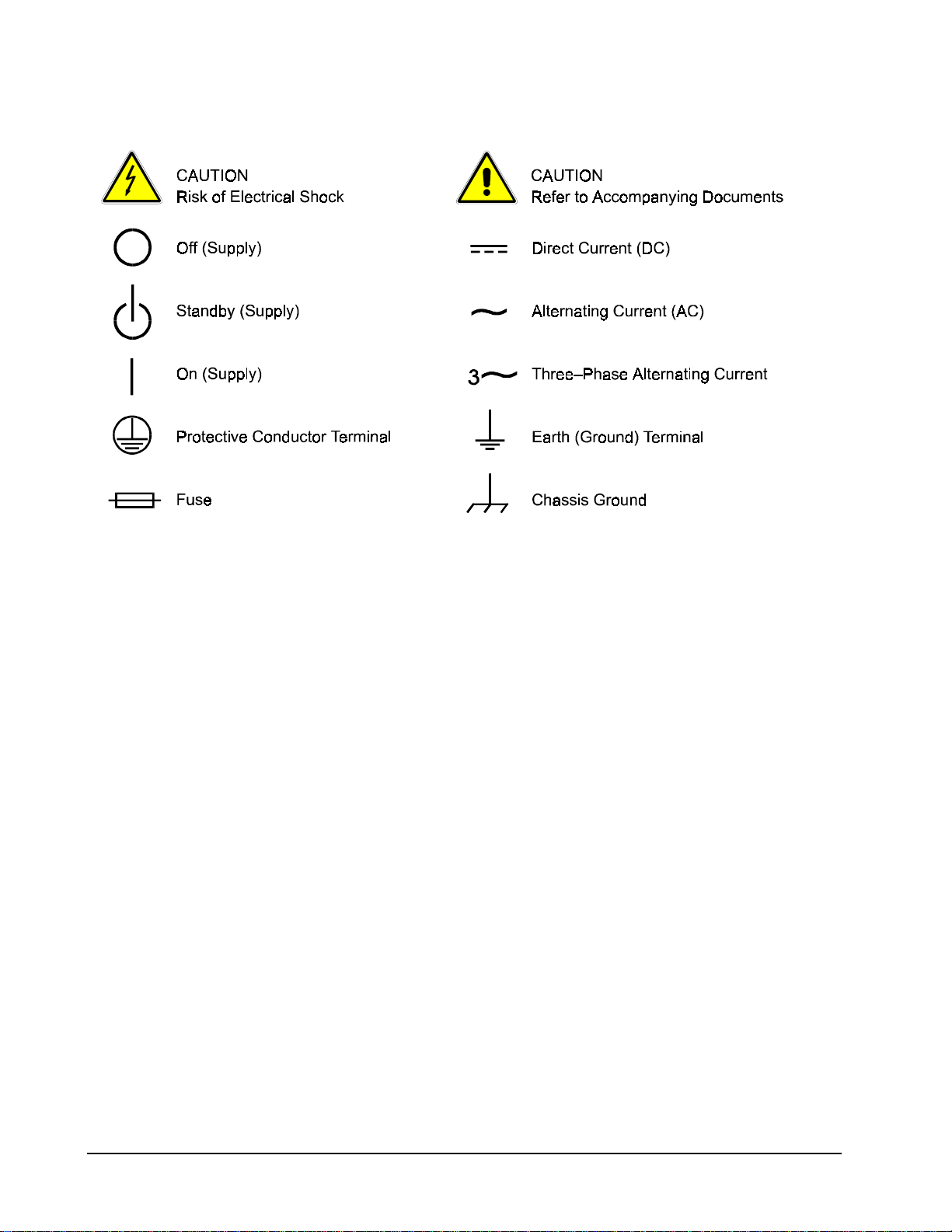
SAFETY SYMBOLS
ii
Page 5

ELGAR FIVE–YEAR WARRANTY
Elgar Electronics Corporation (hereinafter referred to as Elgar) warrants its products to be free from defects in
material and workmanship. This warranty is effective for one year from the date of shipment of the product to
the original purchaser. Liability of Elgar under this warranty shall exist provided that:
• the Buyer exposes the product to normal use and service and provides normal maintenance on the
product;
• Elgar is promptly notified of defects by the Buyer and that notification occurs within the warranty period;
• the Buyer receives a Return Material Authorization (RMA) number from Elgar’s Repair Department prior to
the return of the product to Elgar for repair, phone 800-73-ELGAR (800-733-5427), ext. 2295;
• the Buyer returns the defective product in the original, or equivalent, shipping container;
• if, upon examination of such product by Elgar it is disclosed that, in fact, a defect in materials and/or
workmanship does exist, that the defect in the product was not caused by improper conditions, misuse,
or negligence; and,
• that Elgar QA seal and nameplates have not been altered or removed and the equipment has not been
repaired or modified by anyone other than Elgar authorized personnel.
This warranty is exclusive and in lieu of all other warranties, expressed or implied, including, but not limited
to, implied warranties of merchantability and fitness of the product to a particular purpose. Elgar, its agents,
or representatives shall in no circumstance be liable for any direct, indirect, special, penal, or consequential
loss or damage of any nature resulting from the malfunction of the product. Remedies under this warranty
are expressly limited to repair or replacement of the product.
CONDITIONS OF WARRANTY
• To return a defective product, contact an Elgar representative or the Elgar factory for an RMA number.
Unauthorized returns will not be accepted and will be returned at the shipper’s expense.
• For Elgar products found to be defective within thirty days of receipt by the original purchaser, Elgar will
absorb all ground freight charges for the repair. Products found defective within the warranty period, but
beyond the initial thirty-day period, should be returned prepaid to Elgar for repair. Elgar will repair the unit
and return it by ground freight pre-paid.
• Normal warranty service is performed at Elgar during the weekday hours of 7:30 am to 4:30 pm Pacific
time. Warranty repair work requested to be accomplished outside of normal working hours will be subject to
Elgar non-warranty service rates.
• Warranty field service is available on an emergency basis. Travel expenses (travel time, per diem expense,
and related air fare) are the responsibility of the Buyer. A Buyer purchase order is required by Elgar prior to
scheduling.
• A returned product found, upon inspection by Elgar, to be in specification is subject to an inspection fee and
applicable freight charges.
• Equipment purchased in the United States carries only a United States warranty for which repair must be
accomplished at the Elgar factory.
Committed to Quality...Striving for Excellence
iii
Page 6

This page intentionally left blank.
iv
Page 7

CONTENTS
SECTION 1 M51A OPTION OVERVIEW
1.1 Introduction ...................................................................................................... 1-1
1.2 General Description ......................................................................................... 1-1
1.3 Specifications................................................................................................... 1-2
1.3.1 Electrical Specifications ....................................................................... 1-2
1.3.2 Supplemental Characteristics .............................................................. 1-2
SECTION 2 ISOLATED REMOTE ANALOG INTERFACE OPERATION
2.1 INTFC SETUP Switch...................................................................................... 2-1
2.1.1 INTFC SETUP Switch Functions ......................................................... 2-2
2.2 SETUP Switch ................................................................................................. 2-2
2.3 Isolated Analog Interface Connector ............................................................... 2-3
2.3.1 ISOLATED ANALOG INTERFACE Functions ..................................... 2-5
2.4 Remote Programming Configuration ............................................................... 2-7
2.4.1 Voltage Source Programming of Output Voltage................................. 2-8
2.4.2 Voltage Source Programming of Output Current................................. 2-8
2.4.3 Voltage Source Programming of OVP ................................................. 2-8
2.4.4 Resistance Programming of Output Voltage ....................................... 2-9
2.4.5 Resistance Programming of Output Current........................................ 2-9
2.4.6 Resistance Programming of OVP...................................................... 2-10
2.4.7 4-20mA Current Source Programming of Output Voltage ................. 2-10
2.4.8 4-20mA Current Source Programming of Output Current.................. 2-10
2.5 EXTERNAL-OFF Control............................................................................... 2-11
2.6 Remote Monitoring ........................................................................................ 2-11
2.7 Remote Digital Status Signals ....................................................................... 2-12
M51A Option v
Page 8

Contents DLM 600W Series
LIST OF TABLES
Table 2–1. INTFC SETUP Switch............................................................................... 2-1
Table 2–2. ISOLATED ANALOG INTERFACE Connector Pinout .............................. 2-4
Table 2–3. Remote Programming Configuration Options ........................................... 2-7
Table 2–4. Remote Monitoring................................................................................. 2-11
Table 2–5. Remote Digital Status Signals ............................................................... 2-12
LIST OF FIGURES
Figure 2–1. Rear Panel View, Low–Voltage Models................................................... 2-3
Figure 2–2. Rear Panel View, High–Voltage Models.................................................. 2-3
vi M51A Option
Page 9

SECTION 1
M51A OPTION OVERVIEW
1.1 Introduction
This addendum is to be used in conjunction with the DLM 600W Series Power Supplies
Operation Manual, Sorensen Document No. M362161-01.
The Sorensen M51A Option for the DLM 600W Series power supplies provides a remote analog
interface, which has safety isolation from the output terminals. This allows the remote analog
interface to be connected to user accessible (SELV) control circuits, even though the output
terminals were floated at a high potential with respect to the chassis.
1.2
The M51A Option provides isolation for all programming, monitoring, and digital I/O signals that
are available through the remote analog interface. This isolation barrier eliminates the
connection that exists in the standard DLM models between the non-isolated remote interface
circuits and the output return (negative) terminal. The M51A Option remote analog signals are
referenced to chassis, and could be user accessible irrespective of the float potentials that exist
at the output terminals.
General Description
The M51A Option provides a full complement of programming, monitoring, and control methods.
Remote programming is available for output voltage, current, and overvoltage protection (OVP).
Analog output monitor signals are available for the output voltage and current. Digital I/O
signals provide indication of the operational state, and a means of enabling the remote interface
and the output.
The type and range of the control and monitor signals are user-selectable with a rear panel
setup switch. The output voltage, current, and OVP could be programmed with a 0-5VDC,
0-10VDC, or 0-5kΩ resistance; in addition, the output voltage and current could be programmed
with 4-20mA signals. The output voltage and current monitors could produce 0-5VDC,
0-10VDC, or 4-20mA signals. Isolated 1mA current sources are provided to facilitate the
utilization of 0-5kΩ programming resistances.
Except for the isolated remote analog interface, the installation and operation of the DLM 600W
Series power supplies remains as presented in the Operation Manual. The following sections
provide a detailed description of the new features and the differences in operation.
M51A Option 1-1
Page 10

M51A Option Overview DLM 600W Series
1.3 Specifications
1.3.1
Remote Voltage Programming Accuracy, 0-5/10V Inputs:
Output Voltage: 0.5% of Vmax
Output Current: 0.75% of Imax
OVP: 1.0% of 1.1 X Vmax
Remote 4-20mA Programming Accuracy:
Output Voltage: 0.75% of Vmax
Output Current: 1.0% of Imax
1.3.2
Remote Resistance Programming Accuracy, 0-5kΩ Input:
Output Voltage: 1.0% of Vmax
Output Current: 1.5% of Imax
OVP: 1.5% of 1.1 X Vmax
Remote Monitor Accuracy:
Output Voltage, 0-5/10V ranges: 0.5% of Vmax
Output Voltage, 4-20mA: 0.75% of Vmax
Output Current, 0-5/10V ranges: 0.75% of Imax
Output Current, 4-20mA: 1.0% of Imax
Electrical Specifications
Supplemental Characteristics
1-2 M51A Option
Page 11

SECTION 2
ISOLATED REMOTE ANALOG
INTERFACE OPERATION
2.1
The INTFC SETUP (Interface Setup) switch is accessible from the rear panel of the unit. It
provides user selectability of the programming/monitoring ranges and signal types, as well as
configuring the power supply for operation under remote control. Setting a switch to the UP
position enables a function. The factory default settings are all switch positions OFF (down).
See Figure 2–1 for a rear panel view of low-voltage models DLM5–75M51A, DLM 8–75M51A,
DLM 20–30M51A, DLM 40–15M51A, and DLM 60–10M51A. Refer to Figure 2–2 for a rear
panel view of high-voltage models DLM 80–7.5M51A, DLM 150–4M51A, and DLM 300–2M51A.
Switch
Position
INTFC SETUP Switch
Function OFF (Down) Position ON (Up) Position
1 V, 10V or 4-20mA Select 0-5VDC 0-10VDC or 4-20mA
2 I, 10V or 4-20mA Select 0-5VDC 0-10VDC or 4-20mA
3 OVP, 10V Select 0-5VDC 0-10VDC
4 VMON, 10V Select 0-5VDC or 4-20mA 0-10VDC
5 IMON, 10V Select 0-5VDC or 4-20mA 0-10VDC
6
7 LCK-OUT
8 Not Used — —
EXT-OFF, Active-Low
Select
Active-High Logic Level Active-Low Logic Level
Enable Front Panel
Controls
Lockout Front Panel
Table 2–1. INTFC SETUP Switch
M51A Option 2-1
Page 12

Isolated Remote Analog Interface Operation DLM 600W Series
2.1.1
The following sections describe the functions of the various switch positions:
V, 10V or 4-20mA Select: Position-1, when ON, selects 0-10VDC programming of the output
voltage. Also, must be set to ON position when the ISOLATED ANALOG INTERFACE
connector is wired for 4-20mA output voltage programming. When OFF, selects 0-5VDC
programming of the output voltage.
I, 10V or 4-20mA Select: Position-2, when ON, selects 0-10VDC programming of the output
current. Also, must be set to ON position when the ISOLATED ANALOG INTERFACE
connector is wired for 4-20mA output current programming. When OFF, selects 0-5VDC
programming of the output current.
OVP, 10V Select: Position-3, when ON, selects 0-10VDC programming of OVP threshold.
When OFF, selects 0-5VDC programming of OVP threshold.
VMON, 10V Select: Position-4, when ON, selects 0-10VDC range for readback of output
voltage. When OFF, selects 0-5VDC readback of output voltage. Also, must be set to OFF
position when the ISOLATED ANALOG INTERFACE connector is wired for 4-20mA output
voltage readback.
IMON, 10V Select: Position-5, when ON, selects 0-10VDC range for readback of output current.
When OFF, selects 0-5VDC readback of output current. Also, must be set to OFF position
when the ISOLATED ANALOG INTERFACE connector is wired for
4-20mA output current readback.
EXT-OFF, Active-Low Select: Position-6, when ON, selects the ACTIVE-LOW logic level for
disabling the output with the EXTERNAL-OFF signal of the ISOLATED ANALOG INTERFACE
connector. When OFF, selects the ACTIVE-HIGH logic level for disabling the output with the
EXTERNAL-OFF signal of the Isolated Analog Interface connector.
LCK-OUT: Position-7, when ON, disables the front panel controls; the front panel
LOCAL(REMOTE) switch will not toggle between the front panel and remote control.
Position-8: Not used
INTFC SETUP Switch Functions
2.2
Only two positions of the SETUP switch remain functional: Position-1, REM SNS, for remote
sensing selection; Position-2, SLAVE, for master/slave selection. Their operation is the same
as presented in the Operation Manual. The other switch positions, Position-3 through
Position-8, are not used.
2-2 M51A Option
SETUP Switch
Page 13

DLM 600W Series Isolated Remote Analog Interface Operation
Figure 2–1. Rear Panel View, Low–Voltage Models
Figure 2–2. Rear Panel View, High–Voltage Models
M51A Option 2-3
Page 14

Isolated Remote Analog Interface Operation DLM 600W Series
2.3 Isolated Analog Interface Connector
The ISOLATED ANALOG INTERFACE connector is a 25-position female
Subminiature-D type.
Pin Function
1 ANALOG-CONTROL input
2 Return for 0-5/10V monitor outputs and EXTERNAL-OFF
3 OVP programming input
4 Voltage monitor output, 4-20mA
5 VOLTAGE-MODE status output
6 Return for 4-20mA monitor outputs, Auxiliary 5VDC, and digital I/O
7 Current monitor output, 0-5/10V
8 1.25VDC output for 4-20mA voltage programming signal
9 Voltage programming input
10 Current programming input
11 1.25VDC output for 4-20mA current programming signal
12 Return for 0-5/10V or resistance programming signals
13 Return for 4-20mA current programming signal
14 EXTERNAL-OFF input
15 Auxiliary 5VDC output (+)
16 OVP resistance programming output, 1mA source
17 OVP status output
18 FAULT status output
19 Voltage monitor output, 0-5/10V
20 1.25V input for 4-20mA voltage programming signal
21 Voltage resistance programming output, 1mA source
22 Current resistance programming output, 1mA source
23 1.25V input for 4-20mA current programming signal
24 Current monitor output, 4-20mA
25 Return for 4-20mA voltage programming
Table 2–2. ISOLATED ANALOG INTERFACE Connector Pinout
CAUTION
The signals of the ISOLATED ANALOG INTERFACE have an internal
connection to chassis ground. Damage could result if the voltage from
signal returns, Pin-2, 6, 12, 13, and 25, to chassis ground exceeds
15VDC.
2-4 M51A Option
Page 15

DLM 600W Series Isolated Remote Analog Interface Operation
2.3.1 ISOLATED ANALOG INTERFACE Functions
The following sections describe the functions of the various signals of the ISOLATED ANALOG
INTERFACE. Pin numbers correspond to the connector pinout of Table 2–2.
Digital Control Input Signals
ANALOG-CONTROL: Pin-1, enables remote analog programming with an active-high logic
level of 3-15VDC. An internal 100kΩ pull-down resistor is provided. When ANALOGCONTROL is asserted, the power supply will power-up with the analog interface in control of the
output voltage. Signal is referenced to Pin-6. Circuit is SELV, and has electrical isolation from
the output of the unit.
EXTERNAL-OFF: Pin-14, disables the output when asserted. Active logic level could be
selected with the INTFC SETUP switch to be high (3-30VDC) or low. An internal 100kΩ pulldown resistor is provided. Signal is referenced to Pin-2. Circuit is SELV, and has electrical
isolation from the output of the unit.
Digital Control Output Signals
VOLTAGE-MODE: Pin-5, nominal 5VDC logic level indicates operation in constant-voltage
mode. Source resistance is 2kΩ. Signal is referenced to Pin-6. Circuit is SELV, and has
electrical isolation from the output of the unit.
OVP: Pin-17, nominal 5VDC logic level indicates that the output has been disabled because of
overvoltage protection. Source resistance is 2kΩ. Signal is referenced to Pin-6. Circuit is
SELV, and has electrical isolation from the output of the unit.
FAULT: Pin-18, nominal 5VDC logic level indicates that the output is disabled because of
overtemperature or summary fault. Source resistance is 2kΩ. Signal is referenced to Pin-6.
Circuit is SELV, and has electrical isolation from the output of the unit.
Analog Monitor Signals
VOLTAGE MONITOR, 0-5/10V: Pin-19, readback of the output voltage is provided with a
0-5VDC or 0-10VDC signal (user selectable with INTFC SETUP switch) indicating
0-100% of full scale output. Signal is referenced to Pin-2. Circuit is SELV, and has electrical
isolation from the output of the unit.
VOLTAGE MONITOR, 4-20mA: Pin-4, readback of the output voltage is provided with a
4-20mA signal indicating 0-100% of full scale output. Signal return for the 4-20mA current is
Pin-6. Circuit is SELV, and has electrical isolation from the output of the unit.
CURRENT MONITOR, 0-5/10V: Pin-7, readback of the output current is provided with a
0-5VDC or 0-10VDC signal (user selectable with INTFC SETUP switch) indicating
0-100% of full scale output. Signal is referenced to Pin-2. Circuit is SELV, and has electrical
isolation from the output of the unit.
CURRENT MONITOR, 4-20mA: Pin-24, readback of the output current is provided with a
4-20mA signal indicating 0-100% of full scale output. Signal return for the 4-20mA current is
Pin-6. Circuit is SELV, and has electrical isolation from the output of the unit.
M51A Option 2-5
Page 16

Isolated Remote Analog Interface Operation DLM 600W Series
Analog Programming Signals
OVP PROGRAMMING INPUT: Pin-3, an input signal of 0-5 volts or 0-10 volts (user selectable
with INTFC SETUP switch) programs the OVP threshold from 5-110% of full scale output
voltage. Signal is referenced to Pin-12. Circuit is SELV, and has electrical isolation from the
output of the unit.
VOLTAGE PROGRAMMING INPUT: Pin-9, an input signal for two methods of programming the
output voltage: 0-5/10V voltage source or 4-20mA current source.
An input signal of 0-5VDC or 0-10VDC (user selectable with INTFC SETUP switch) to Pin-9
programs the output voltage 0-100% of full scale. Signal is referenced to Pin-12.
An input signal of 4-20mA (user selectable with INTFC SETUP switch) to Pin-9 programs the
output voltage 0-100% of full scale. Two jumpers are also required:
Pin-20 to Pin-8; Pin-25 to Pin-12. Signal return for the 4-20mA current is Pin-25; resultant
burden voltage is referenced to Pin-12.
Circuits are SELV, and have electrical isolation from the output of the unit.
CURRENT PROGRAMMING INPUT: Pin-10, an input signal for two methods of programming
the output current: 0-5/10V voltage source or 4-20mA current source.
An input signal of 0-5VDC or 0-10VDC (user selectable with INTFC SETUP switch) to Pin-10
programs the output current 0-100% of full scale. Signal is referenced to Pin-12.
An input signal of 4-20mA (user selectable with INTFC SETUP switch) to Pin-10 programs the
output current 0-100% of full scale. Two jumpers are also required:
Pin-23 to Pin-11; Pin-13 to Pin-12. Signal return for the 4-20mA current is Pin-13; resultant
burden voltage is referenced to Pin-12.
Circuits are SELV, and have electrical isolation from the output of the unit.
OVP RESISTANCE PROGRAMMING OUTPUT: Pin-16 provides a 1mA current source which
would be connected to Pin-3, OVP PROGRAMMING INPUT, with a 0-5kΩ external resistor
connected between Pin-16 to Pin-12, to program the OVP threshold from 5-110% of full scale
output voltage. The INTFC SETUP switch Position-3, OVP, must be set to OFF (down) to
select 0-5VDC input range. Circuit is SELV, and has electrical isolation from the output of the
unit.
VOLTAGE RESISTANCE PROGRAMMING OUTPUT: Pin-21 provides a 1mA current source
which would be connected to Pin-9, VOLTAGE PROGRAMMING INPUT, with a 0-5kΩ external
resistor connected between Pin-21 to Pin-12, to program the output voltage from 0-100% of full
scale output. The INTFC SETUP switch Position-1, V, must be set to OFF (down) to select
0-5VDC input range. Circuit is SELV, and has electrical isolation from the output of the unit.
2-6 M51A Option
Page 17

DLM 600W Series Isolated Remote Analog Interface Operation
CURRENT RESISTANCE PROGRAMMING OUTPUT: Pin-22 provides a 1mA current source
which would be connected to Pin-10, CURRENT PROGRAMMING INPUT, with a 0-5kΩ
external resistor connected between Pin-22 to Pin-12, to program the output current from
0-100% of full scale output. The INTFC SETUP switch Position-2, I, must be set to OFF (down)
to select 0-5VDC input range. Circuit is SELV, and has electrical isolation from the output of the
unit.
Auxiliary Sources
AUXILIARY 5VDC OUTPUT: Pin-15, 5VDC source output for use with logic and programming
circuits. Source capability is adequate to provide for full scale programming of output voltage,
current, or OVP when the user connects it to the appropriate programming input(s). Source is
referenced to Pin-6. Maximum output current is 15mA. Circuit is SELV, and has electrical
isolation from the output of the unit.
AUXILIARY 5VDC RETURN: Pin-6, return of 5VDC AUXILIARY source output. Circuit is
SELV, and has electrical isolation from the output of the unit.
1.25VDC REFERENCE FOR 4-20mA VOLTAGE PROGRAMMING: Pin-20, provides a
1.25VDC reference utilized by internal circuits associated with 4-20mA programming of output
voltage.
1.25VDC REFERENCE FOR 4-20mA CURRENT PROGRAMMING: Pin-11, provides a
1.25VDC reference utilized by internal circuits associated with 4-20mA programming of output
current.
2.4 Remote Programming Configuration
Table 2–3 presents the options for remote control operation. Pin numbers refer to the
ISOLATED ANALOG INTERFACE connector. Switch position numbers refer to the INTFC
SETUP switch on the rear panel.
Mode of
Operation
Remote Only High Level ON (Up) Remote No
ANALOG-
CONTROL
Signal, Pin-1
LCK-OUT, INTFC
Setup Switch
Position-7
Power-Up
State
Local/Remote
Toggling
Local Only Low or Open Off (Down) Local No
Local/Remote High Level OFF (Down) Remote Yes
Table 2–3. Remote Programming Configuration Options
M51A Option 2-7
Page 18

Isolated Remote Analog Interface Operation DLM 600W Series
2.4.1
Setting up for voltage source programming of the output voltage is as follows:
1. Set Position-1, V, of the INTFC SETUP switch to OFF (down) for 0-5VDC programming
2. Set Position-1, V, of the INTFC SETUP switch ON (up) for 0-10VDC programming
3. Connect the external programming voltage source to the ISOLATED ANALOG
4. Program the other parameters to the desired limit values: CURRENT PROGRAMMING
5. Connect Pin-1, ANALOG-CONTROL, of the ISOLATED ANALOG INTERFACE
2.4.2
Setting up for voltage source programming of the output current is as follows:
1. Set Position-2, I, of the INTFC SETUP switch to OFF (down) for 0-5VDC programming
2. Set Position-2, I, of the INTFC SETUP switch ON (up) for 0-10VDC programming range.
3. Connect the external programming voltage source to the ISOLATED ANALOG
4. Program the other parameters to the desired limit values: VOLTAGE PROGRAMMING
5. Connect Pin-1, ANALOG-CONTROL, of the ISOLATED ANALOG INTERFACE
Voltage Source Programming of Output Voltage
range.
range.
INTERFACE connector, with positive to Pin-9 and negative to Pin-12.
INPUT, Pin-10, and the OVP PROGRAMMING INPUT, Pin-3, with respect to pin-12.
connector to Pin-15.
Voltage Source Programming of Output Current
range.
INTERFACE connector, with positive to Pin-10 and negative to Pin-12.
INPUT, Pin-10, and the OVP PROGRAMMING INPUT, Pin-3, with respect to pin-12.
connector to Pin-15.
2.4.3
Setting up for voltage source programming of OVP is as follows:
1. Set Position-3, OVP, of the INTFC SETUP switch to OFF (down) for 0-5VDC
2. Set Position-3, OVP, of the INTFC SETUP switch ON (up) for 0-10VDC programming
3. Connect the external programming voltage source to the ISOLATED ANALOG
2-8 M51A Option
Voltage Source Programming of OVP
programming range.
range.
INTERFACE connector, with positive to Pin-3 and negative to Pin-12.
Page 19

DLM 600W Series Isolated Remote Analog Interface Operation
4. Program the other parameters to the desired limit values: VOLTAGE PROGRAMMING
INPUT, Pin-9, and the CURRENT PROGRAMMING INPUT, Pin-10, with respect to
Pin-12.
5. Connect Pin-1, ANALOG-CONTROL, of the ISOLATED ANALOG INTERFACE
connector to Pin-15.
2.4.4
Setting up for resistance programming of the output voltage is as follows:
1. Set Position-1, V, of the INTFC SETUP switch to OFF (down) for 0-5VDC programming
2. Connect the external programming resistance, 0-5kΩ, to the ISOLATED ANALOG
3. Connect a jumper from Pin-21 to Pin-9.
4. Program the other parameters to the desired limit values: CURRENT PROGRAMMING
5. Connect Pin-1, ANALOG-CONTROL, of the ISOLATED ANALOG INTERFACE
2.4.5
Setting up for resistance programming of the output current is as follows:
1. Set Position-2, I, of the INTFC SETUP switch to OFF (down) for 0-5VDC programming
2. Connect the external programming resistance, 0-5kΩ, to the ISOLATED ANALOG
3. Connect a jumper from Pin-22 to Pin-10.
4. Program the other parameters to the desired limit values: VOLTAGE PROGRAMMING
5. Connect Pin-1, ANALOG-CONTROL, of the ISOLATED ANALOG INTERFACE
Resistance Programming of Output Voltage
range.
INTERFACE connector, from Pin-21 to Pin-12.
INPUT, Pin-10, and the OVP PROGRAMMING INPUT, Pin-3, with respect to Pin-12.
connector to Pin-15.
Resistance Programming of Output Current
range.
INTERFACE connector, from Pin-22 to Pin-12.
INPUT, Pin-9, and the OVP PROGRAMMING INPUT, Pin-3, with respect to Pin-12.
connector to Pin-15.
M51A Option 2-9
Page 20

Isolated Remote Analog Interface Operation DLM 600W Series
2.4.6
Setting up for resistance programming OVP is as follows:
1. Set Position-3, OVP, of the INTFC SETUP switch to OFF (down) for 0-5VDC
2. Connect the external programming resistance, 0-5kΩ, to the ISOLATED ANALOG
3. Connect a jumper from Pin-16 to Pin-3.
4. Program the other parameters to the desired limit values: VOLTAGE PROGRAMMING
5. Connect Pin-1, ANALOG-CONTROL, of the ISOLATED ANALOG INTERFACE
2.4.7
Setting up for 4-20mA programming of the output voltage is as follows:
1. Set Position-1, V, of the INTFC SETUP switch to OFF (down) for 0-5VDC programming
2. Connect the external 4-20mA programming current source to the ISOLATED ANALOG
3. Connect a jumper from Pin-25 to Pin-12.
4. Connect a jumper from Pin-8 to Pin-20.
5. Program the other parameters to the desired limit values: CURRENT PROGRAMMING
6. Connect Pin-1, ANALOG-CONTROL, of the ISOLATED ANALOG INTERFACE
Resistance Programming of OVP
programming range.
INTERFACE connector, from Pin-16 to Pin-12.
INPUT, Pin-9, and the CURRENT PROGRAMMING INPUT, Pin-10, with respect to pin-
12.
connector to Pin-15.
4-20mA Current Source Programming of Output Voltage
range.
INTERFACE connector, with source at Pin-9 and return at Pin-25.
INPUT, Pin-10, and the OVP PROGRAMMING INPUT, Pin-3, with respect to pin-12.
connector to Pin-15.
2.4.8
Setting up for 4-20mA programming of the output current is as follows:
1. Set Position-2, I, of the INTFC SETUP switch to OFF (down) for 0-5VDC programming
2. Connect the external 4-20mA programming current source to the ISOLATED ANALOG
2-10 M51A Option
4-20mA Current Source Programming of Output Current
range.
INTERFACE connector, with source at Pin-10 and return at Pin-13.
Page 21

DLM 600W Series Isolated Remote Analog Interface Operation
3. Connect a jumper from Pin-13 to Pin-12.
4. Connect a jumper from Pin-11 to Pin-23.
5. Program the other parameters to the desired limit values: VOLTAGE PROGRAMMING
INPUT, Pin-9, and the OVP PROGRAMMING INPUT, Pin-3, with respect to pin-12.
6. Connect Pin-1, ANALOG-CONTROL, of the ISOLATED ANALOG INTERFACE
connector to Pin-15.
2.5
The EXTERNAL-OFF control input provides the same functionality as the OUTPUT switch on
the front panel. When asserted, it will turn off the output converter, discharge the output
capacitors with the downprogrammer, and reset the OVP and FAULT monitors. The signal
could be configured to be either active-low or active-high with the INTFC SETUP switch on the
rear panel.
Set Position-6, /EXT-OFF, to the OFF (down) position to select the active-high logic level for
asserting EXTERNAL-OFF. Set Position-6, /EXT-OFF, to the ON (up) position to select the
active-low logic level for asserting EXTERNAL-OFF. The logic-high level could be produced
with a voltage source within the range of 3-30VDC, and would be connected to Pin14, positive,
and Pin-2, return. The circuit is SELV, and has electrical isolation from the output of the unit.
2.6
Analog signals are available for monitoring the output voltage and current. These signals vary
proportionally to the output parameters, and have user selectable ranges of 0-5VDC, 0-10VDC,
or 4-20mA for an output change from zero to full scale. Refer to Table 2–4 for information on
configuring the monitors.
EXTERNAL-OFF Control
Remote Monitoring
Output
Monitor
Signal
ISOLATED ANALOG
INTERFACE Connections
Signal Return Position Setting
INTFC SETUP Switch
Signal
Range
Voltage Pin-19 Pin-2 4, VMON OFF (down) 0-5VDC
Voltage Pin-19 Pin-2 4, VMON ON (up) 0-10VDC
Voltage Pin-4 Pin-6 4, VMON OFF (down) 4-20mA
Current Pin-7 Pin-2 5, IMON OFF (down) 0-5VDC
Current Pin-7 Pin-2 5, IMON ON (up) 0-10VDC
Current Pin-24 Pin-6 5, IMON OFF (down) 4-20mA
Table 2–4. Remote Monitoring
M51A Option 2-11
Page 22

Isolated Remote Analog Interface Operation DLM 600W Series
2.7 Remote Digital Status Signals
Digital signals are available for remote monitoring the operational status of the unit. Refer to
Table 2–5 for information on the characteristics of the signals.
Status
Indicator
Signal
VOLTAGE-
MODE
OVP Pin-17 Pin-6 5V 0V 2kΩ
FAULT Pin-18 Pin-6 5V 0V 2kΩ
ISOLATED ANALOG
INTERFACE Connections
Signal Return Asserted Not Asserted
Pin-5 Pin-6 5V 0V 2kΩ
Table 2–5. Remote Digital Status Signals
Logic Levels (with No
Signal Output Current)
Output
Resistance
2-12 M51A Option
 Loading...