

Page 1

LOUD HAILER
Back
LH-3000, LH-3000-CG
Page 2

Page 3

SAFETY INSTRUCTIONS
WARNING
Do not open the equipment.
Only qualified personnel should work inside
the equipment.
Do not disassemble or modify the
equipment.
Fire, electrical shock or serious injury can
result.
Do not place liquid-filled containers on
the top of the equipment.
Fire or electrical shock can result if a liquid
spills into the equipment.
Immediately turn off the power at the
switchboard if the equipment is emitting
smoke or fire.
CAUTION
Do not use the equipment for other than
its intended purpose.
Use of the equipment for other than its
intended purpose may result in damage to
the equipment or cause bodlily injury.
Observe the following compass safe
distances to prevent interference to a
magnetic compass:
Standard
compass
LH-3000 1.55 m 1.00 m
LH-3010 2.15 m 1.40 m
Steering
compass
Continued use of the equipment can cause
fatal damage to the equipment. Contact a
FURUNO agent for service.
Make sure no rain or water splash leaks
into the equipment.
Fire or electrical shock can result if water
leaks in the equipment.
Keep heater away from equipment.
A heater can melt the equipment's power
cord, which can cause fire or electrical
shock.
Use the proper fuse.
Use of a wrong fuse can result in damage
to the equipment.
i
Page 4

TABLE OF CONTENTS
FOREWORD ........................................................................................................iii
SYSTEM CONFIGURATION................................................................................ iv
EQUIPMENT LIST................................................................................................ iv
1. INSTALLATION................................................................................................1
1.1 Mounting the Loud Hailer..............................................................................................1
1.2 Intercom Speaker (option).............................................................................................3
1.3 Wiring............................................................................................................................4
2. OPERATIONAL OVERVIEW............................................................................9
2.1 Controls.........................................................................................................................9
2.2 Turning the Power On/Off............................................................................................10
2.3 Adjusting Key Backlighting..........................................................................................11
2.4 Adjusting Output Level................................................................................................11
2.5 Adjusting Listening Volume.........................................................................................11
2.6 Calling Al l Intercom Stations........................................................................................11
2.7 Calling a Specific Inter com St ation ..............................................................................12
2.8 Receivin g a Call fr om an Intercom Station...................................................................12
2.9 Hailing by Voice...........................................................................................................13
2.10 Soun ding W arnin g Signals..........................................................................................14
2.11 Transmitting the Auxiliary Signal..................................................................................18
2.12 Alarm Mode.................................................................................................................18
2.13 Siren Mode (LH-3000-CG) ..........................................................................................20
3. MAINTENANCE, TROUBLESHOOTING....................................................... 21
3.1 Preventive Maintenance..............................................................................................21
3.2 Replacing the Fuse.....................................................................................................22
3.3 Troubleshooting...........................................................................................................22
SPECIFICATIONS...........................................................................................SP-1
PACKING LIST
OUTLINE DRAWINGS
INTERCONNECTION DIAGRAM
ii
Page 5

FOREWORD
A Word to the Owner of the LH-3000, LH-3000-CG
Congratul ations on y our c hoice of the FURUNO Loud Hailer LH-3000, LH-3000-CG. We are
confident you will s ee why FURUNO has bec ome sy nonymous with quality and reliability.
For over 50 y ears FURUNO Electric Com pany has enjoyed an enviabl e r eputat ion for
innovati ve a nd dependable marine electronic s equipment. Thi s dedi c ation to excellence i s
furthered by our extensive global netw or k of agents and dealers .
Your Loud Hailer is designed and constr uc ted to meet the rigorous demands of the marine
environme nt. How ever, no machine can perform its int ended function unless i ns talled,
operated an d m aintained properl y. Please carefully read and follow the rec om m ended
procedures f or inst allation, operation and m aintenance.
We would appreciat e hear ing from you, the end- us er, about whether w e ar e achieving our
purposes.
Thank you for consi der ing and purchasing FURUNO equipment .
Features
• Two types of specifications are availabl e: LH-3000 and LH- 3000-CG ( for U.S. Coast
Guard). The tw o are al m ost identi c al; the LH-3000-CG is additionally equipped with a
Siren M ode. (Unless other wise noted “ LH- 3000” r efers to both LH-3000 and
LH-3000-CG.)
• 30 W audio output power to get another boat’s attention under almost any condi tion.
• Eight internationally ac c epted warning s ignals can be selected for automati c oper ation for
a variety of differ ent maritime situations alerting nearby vessels of your pr es enc e and
status in low visi bility conditions.
• Four i ntercom st ations (speaker s ) m ay be connected to get 2- way comm unications
between m as ter station and one or all interc om stations.
• LED indicators al er t you to equi pment stat us .
• Keys ar e bac klit for nighttim e oper ation.
• Smartly designed and intui tive front panel for ease of operation.
• An auxiliary audio input all ows transmissi on of music or ot her ex ternal audio signal s ( from
cassette pl ayer, CD player, radi o, etc.) to the interc om s peakers, external hor ns or both.
iii
Page 6

v
SYSTEM CONFIGURATION
Intercom Speaker
(Max. 4)
Junction
Box
Forward Horn
After Horn
MIC
External Speaker
Microphone
System c onfiguration
EQUIPMENT LIST
PWR OFF
ALL
IC 1
YELP
FUNC/PTT
MAN
FWD
IC 2
UNWY
STOP
LISTEN
VOL
AFT
BOTH
DIM
IC 4IC 3
AUX
TOW
SAIL
AUTOMATIC
FUNC
ANCH AGND
HAIL
VOL
13.6 VDC
icrophone
ote M
Rem
Auxiliary Audio
Source
Sensor
Alarm
: Standard Supply
: Optional Supply
: Local Supply
Standard supply
Name Type Code No. Qty Remarks
LH-3000 Loud Hailer
1
See packing list for details.
LH-3000-CG
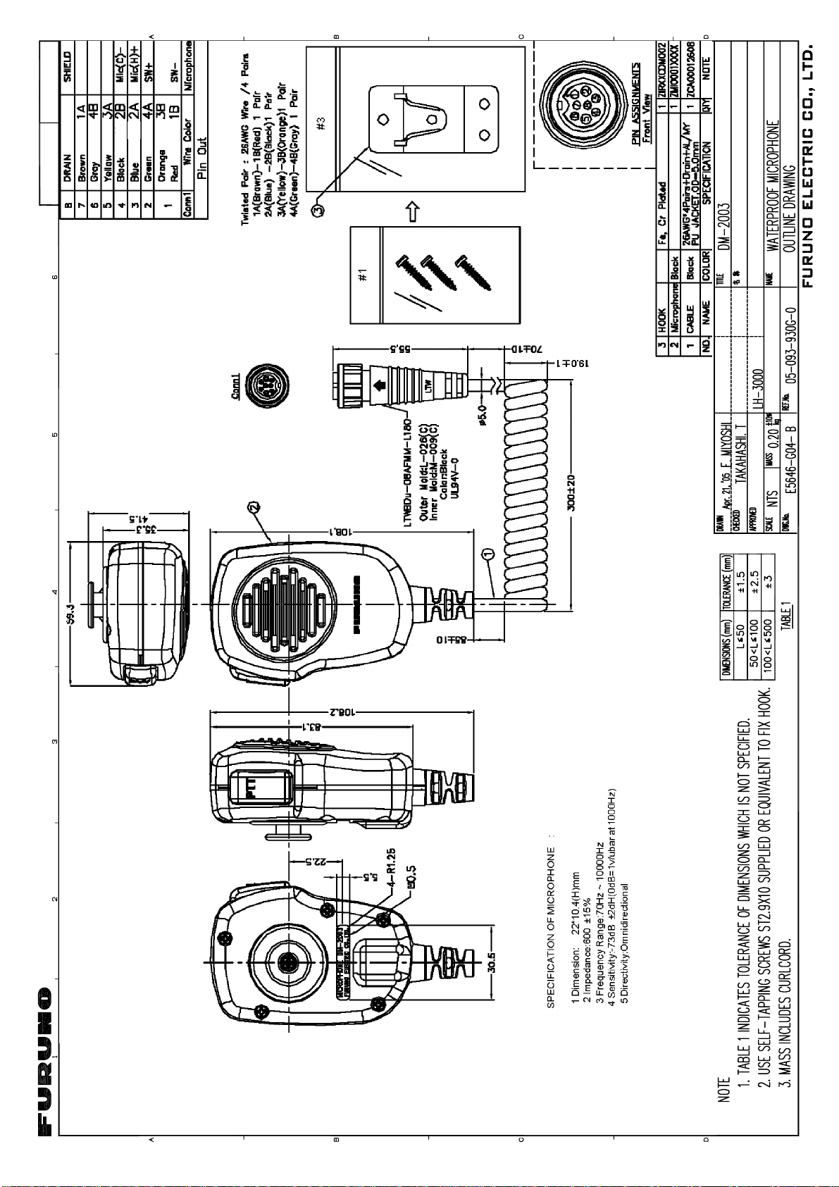
Microphone Set DM-2003 1 set
Installation
1 set
Materials
Spare Parts 1 set
Template E52-00303 000-149-157 1
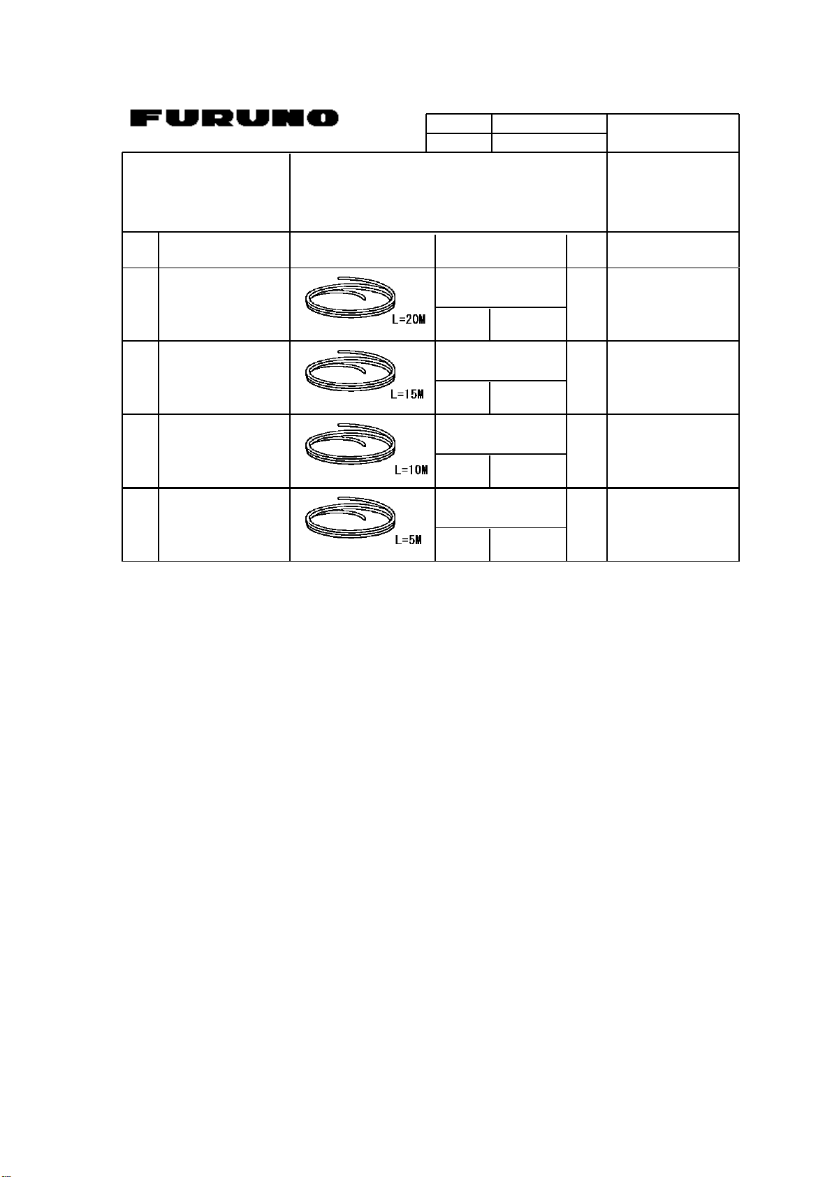
Optional supply
Name Type Code No. Qty Remarks
Intercom Speaker LH-3010 000-149-111 1 Max. 4
Flush Mount Kit LH-3020 000-149-112 1 See packing list.
Twisted Pair Cable CO-SPEVV-SB-C
0.2X2P
000-111-680 1 5 m
000-120-792 1 10 m
000-120-793 1 15 m
000-120-794 1 20 m
i
Page 7

1. INSTALLATION
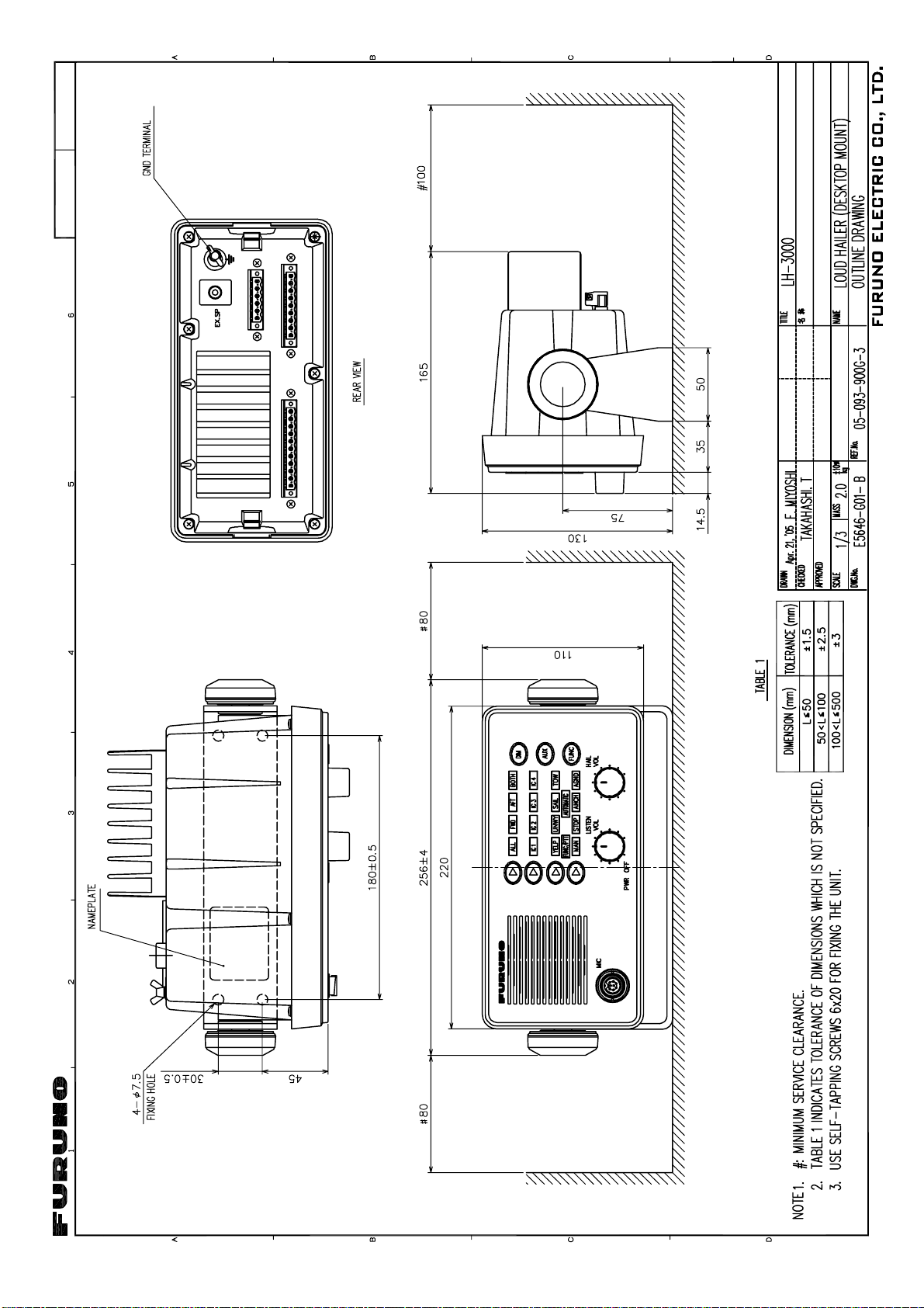
1.1 Mounting the Loud Hailer
The Loud Hailer can be mounted on a desktop, on the overhead, on a bulkhead or f lush
mounted i n a panel (optional ki t required). Refer to the mounting template (supplied) for
installation instructions.
Mounting considerations
When planning the location for t he Loud Hail er, keep in the mind the fol lowing
considerations.
Locate the unit where the front panel can be eas ily viewed and operated.
Leave sufficient space at the sides and rear of your uni t for ease of maintenance.
Locate the unit as near to the power sour c e as pos s ible.
The loc ation should be out of direct sunlight because of heat t hat can build up inside the
cabinet.
Choose a location not subject to rain and salt spr ay.
Locate the unit well away from sourc es of noise such as motors, al ternators a nd
generators.
Mounting procedure
Desktop, bulkhead, overhead mounting
1. At tach rubber cushions (s upplied) to the body
so they locate across from the bott om of the slot i n the hanger regardless of mou nting
method.
of the Loud Hailer. Posit ion the cushi ons
Rubber
cushion
2. Fix the hanger to the mounting location with t apping screws (6x20).
3. Scr ew knob bol ts into t he Loud Hailer.
4. Set the Loud Hailer to the hanger and tight en k nob bolts.
1
Page 8

1. INSTALLATION
Flush mounting
Requires flush mount k it LH-3020 (C ode No. 000-149-112). See the fl us h m ount outline
drawing for det ails.
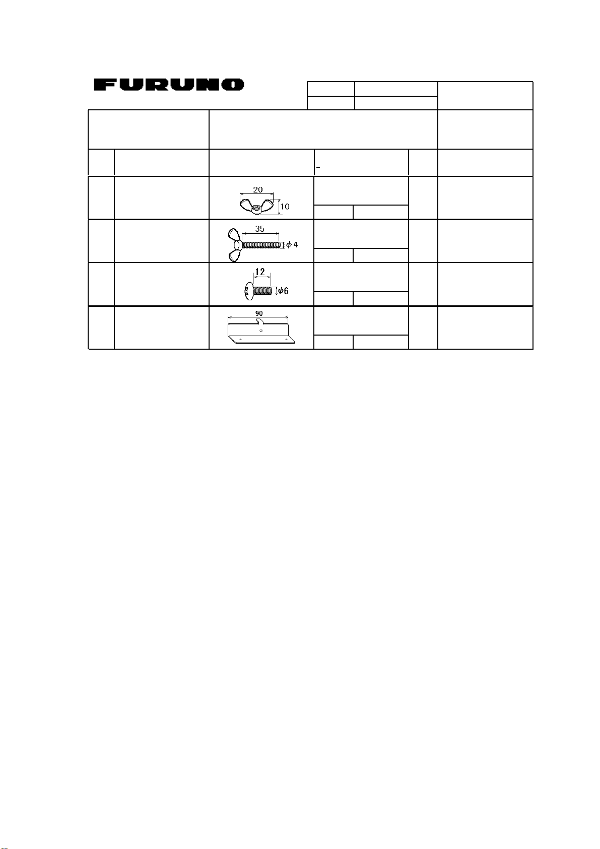
Contents of flush mount kit
Name Type Code No. Qty
Flush Mounting Plate TZ7300012A 999-999-025 2
Screw 6X12 SUS304 999-999-027 2
Wing Screw M4X35 SUS304 999-999-027 4
Wing Nut M4 SUS304 999-999-028 4
1. Make a cutout i n the mounting location referring t o fl us h m ount outline drawing.
2. Place the Loud Hai ler in the c utout.
3. Fix the two flus h m ounting plat es to the Loud Hai ler with s c r ews.
4. Screw the wing nuts on the w ing screws .
5. Fix the Loud Hailer with t he wing bolts and then ti ghten the wing nuts.
Loud hailer, flush mount
2
Page 9

1. INSTALLATION
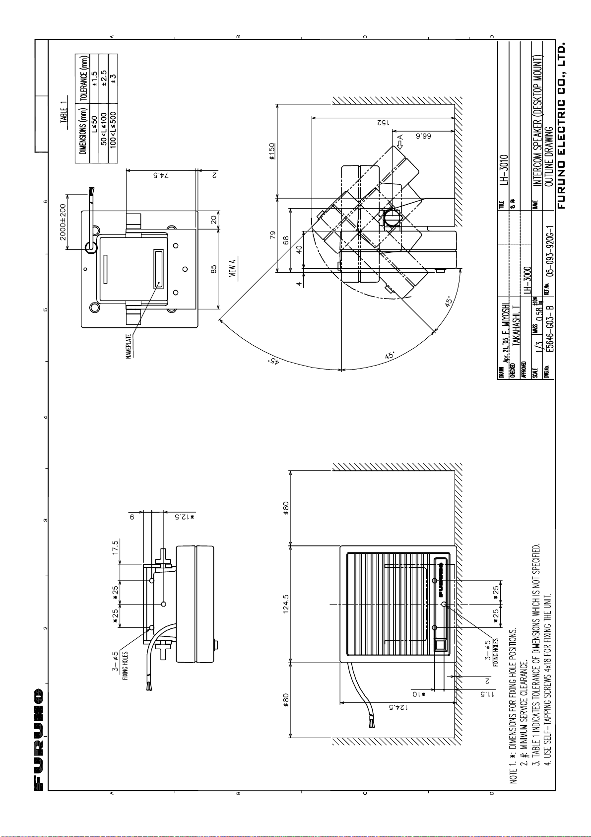
1.2 Intercom Speaker (option)
Four inter c om s peakers (maximum) may be connected to get 2-way communications
between m as ter station and one or all interc om speakers. For m ounting dimens ions and
fixing i ns tructions , see the outl ine drawi ng.
Intercom speaker
3
Page 10

1. INSTALLATION
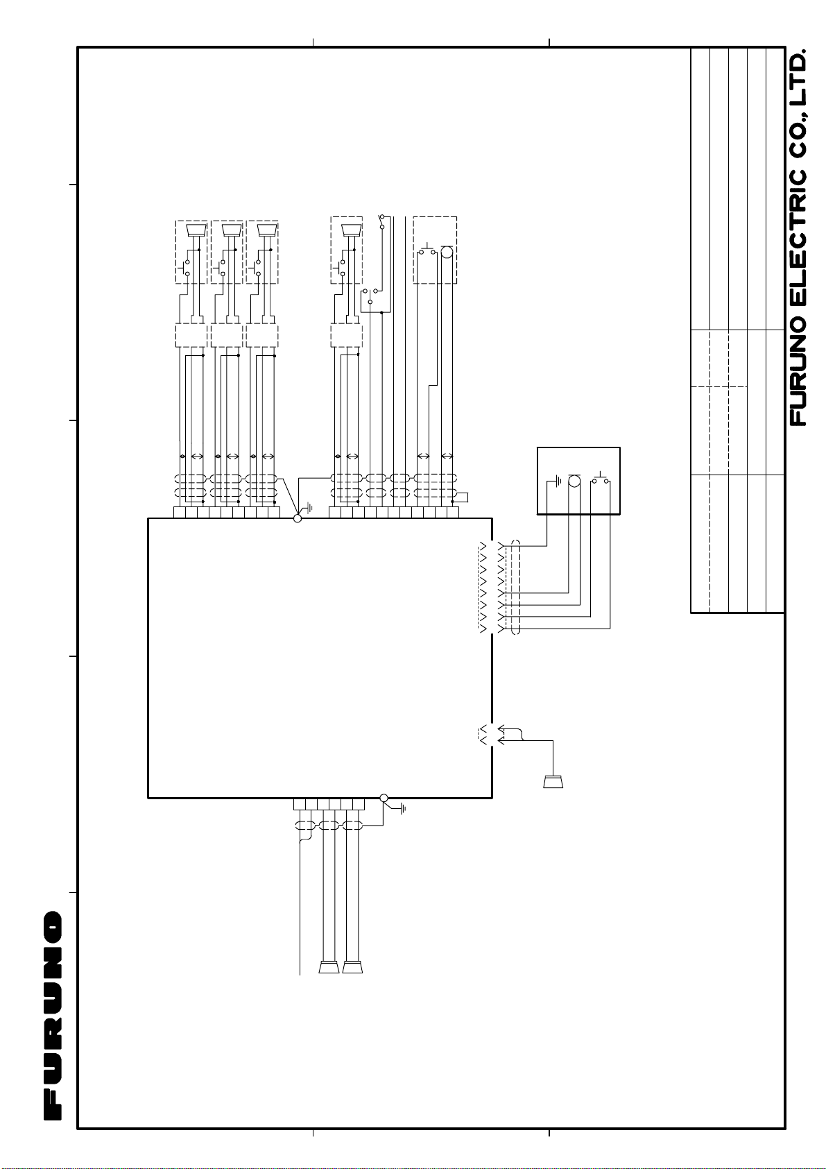
1.3 Wiring
All equipment are termi nated at the r ear panel of the LH-3000. S ee the illustration on the
next page for how to connec t equipment to terminals. Refer to the i nterconnecti on diagram
for detailed information.
Rear panel layout
13.6 VDC (Power),
FWD and AFT
terminals
J1
J3
MIC, AUX, ALRM, PTT, CAL
and SP (intercom speaker #4)
terminals
Connect drain wires of armored cables to the ground terminal.
Do not short them to the heat sink.
NOTICE
J2
SP and CAL (intercon
station #1 - #3) terminals
External Speaker
Ground
Terminal
LH-3000, rear panel
4
Page 11

1. INSTALLATION
Wiring
The illustration below shows how to connect the power supply. Other equipm ent are
connected similarly.
(1) Unfasten screws.
J1
J3
(4) Set terminal;
tighten screws.
- + - + - +
AFT FWD 13.6V
TERMINAL ARRANGEMENT
J1
J2
- +
Jeweler's
screwdriver
(2) Pull out terminal.
(3) Insert wire into terminal,
and tighten screw at top
of terminal.
Note 1 : Connect power cables
to the battery correctly.
- + - + - +
AFT FWD 13.6V
Note 2: Connection of intercom
speaker cable to J2 or J3:
Brown: CAL
J2
SP3 0V2 CAL2 SP1
0V3 CAL3 SP2 0V1 CAL1
Red: SP1
Black: OV1
J3
MIC PTT AUX ALRM SP4
0V 0V 0V 0V 0V4 CAL4
LH-3000, rear panel, how to wire terminals
5
Page 12

1. INSTALLATION
Power connection
The LH-3000 is intended for
use with a 13.6 VDC power
supply. Connect the power
cable (loca l supply) to the
77
Sheath
Drain wire fabrication
15
L*
5
3
Armor
* Length long enough to
reach ground terminal.
Armor
Sheath
terminals labeled “13.6V”.
φ =
Use cable type DPY C-1.5 or
equi v alent. Fabricate the
cable as shown below. For
longer runs the wire size of
Solder drain wire
7
Cut the sheath.
15
10
11.7 mm
DPYC-1.5 Sectional view
Conductor
S = 1.5 mm
φ = 1.56 mm
2
leads should be increased
accordingly to minimize line
losses. The wire connected to the positiv e (+) t erminal must be connected to the positiv e
terminal on the DC power source, and the wire connected to the negativ e terminal (-) must
be connected to the negative t erminal on the DC power source. If the power leads are
rev ersed the fuse (inside t he Loud Hailer) will blow.
Intercom speaker (option)
Up to four intercom speakers may be connected to the intercom speaker terminals labeled
CAL1-CAL4. Connect each speaker to the terminal block according to desired intercom
speaker selection. The cable end is prefabricated. Howev er, to meet EMC requ irements the
length of the cable must be less than 1 m. If the distance between the Loud Hailer and
intercom speaker is greater than 2 m ( max. 20 m) , use a j unction box (l ocal supply) . For the
connection to the j unction box use cable type CO-SPEVV-SB-C 0.2X2P (opt ion) an d
fabricate it as below. In this case, the length of the cable between the j unction box and an
intercom speaker must no be more than 1 m regardless of whether the equipm ent must
meet EMC require ments or not.
Loud Hailer
Distance between loud hailer and intercom speaker is less than 2 m.
Loud Hailer
Distance between loud hailer and intercom speaker is 2-20 m.
Outer sheath
2 m max.
2-20 m max.
Inner sheath
Vinyl
tape
Intercom
Speaker
Junction
Box
45
Remove the outer sheath and
armor by 45 mm.
11
7
Remove the inner sheath by 11 mm,
and the sheath of the cores by 7 mm.
Twist and trim the shield.
Cut the unused cores.
Solder a vinyl wire to the shield.
Vinyl wire
Tape the sheath.
Connection of speaker cable to
J2 or J3 on Loud Hailer:
Brown: CAL, Red: SP1, Black: OV1
1 m max.
Intercom
Speaker
Fabrication of speaker cable
6
Page 13

1. INSTALLATION
Hailer horn (local supply)
Mount the hailer horns ( local supply) faci ng away from t he Loud Hailer to prevent feedback.
They should also be pointed in the opposite direction of the micr ophone as you are
speaking into it. B efore mounting any horn, you should test it with the HAIL feature with the
horn in the desired location to check f or s uitability of mount ing location.
Connect horns to the Loud Hailer with cabl e type DPYC-1.5 or equivalent. (See pag e 6 for
how to fabricate this cable.) B e s ur e the cable is suitabl e for all-w eather use. The
terminat ing point on t he terminal is either FWD or A FT depending on the l oc ation of the
speaker.
Burglar alarm (local supply)
The unit can function as a burglar alarm by connecting an exter nal alarm sens or (local
supply) to the ALRM ter m inals. The alarm sens or s hould be a “norm ally open switch”. Use
cable type TTY CS - 1 or equivalent to connect the sens or. Fabricate the cable as shown
below.
When the sens or c onnected to t he ALRM terminal becom es s horted an d the alarm func tion
is active, the yelp signal is released at maxi mum vol um e through both hailer hor ns.
77
Shield
3
Armor
8
Twist and cut
Drain wire fabrication
L*
15
7
Drain wire
* Length long enough to
reach ground terminal.
5
Solder
15
10
Vinyl tape
φ =
10.1 mm
TTYCS-1 Sectional view
Conductor
S = 0.75 mm
φ = 1.11 mm
Armor
Sheath
Shield
2
Fabricat ion of cable T TYCS-1
7
Page 14

1. INSTALLATION
A
Floating ground
The LH-3000 h as a floati ng gr ound. What this means is t hat the heat si nk gr ound is floating
and will not ground batteries if t hey are c onnec ted to the s hip’s chass is. To maint ain a
floating ground:
1. Use a stereo plug when connecting a 4 ohm speaker to the external speak er plug.
Connect i t as shown i n the i llustration below.
Do not use for battery use for ship's earth only
St er eo plug
2. Do not connect any of the output connectors on the rear panel to t he s hip’s ground.
3. SP outputs ar e floati ng and m us t not be connected to either battery or the rear p anel.
Use a normal two conductor insulated speaker wire for the horn speaker.
Output power
The output power may be s et for 30 W or 20 W, and the default s ettings is 30 W. For 20 W
output contact a FURU NO agent or dealer for details.
Note: I f an external speaker is used it must be capable of handling the rat ed output power.
Siren mode switch (for LH-3000-CG)
To use the siren mode funct ion, connec t a toggle switch whose spec ifications are as shown
below to t he bur glar alarm t er m inal.
SIREN
LH-3000C
ALRM
T oggle switch specifications
4
5
OFF
ALARM
larm SENSOR
Circuit: SPDT (3P)
Swit c hing f unc tion: ON-OFF-ON
Rating: 6A, 250 VAC
Insul ation resistance: 500 VDC, 100 Mohms m in.
Volt age br eak down: 1500 VAC (one minute)
Contact r es istanc e: less than 20 M ohms m ax .
8
Page 15

2. OPERATIONAL OVERVIEW
2.1 Controls
4
3
2
12
11
MIC
1
PWR OFF
ALL
IC 1
YELP
FUNC/PTT
MAN
8
10
FWD
IC 2
UNWY
STOP
LISTEN
VOL
AFT
BOTH
SAIL
AUTOMATIC
ANCH AGND
IC 4IC 3
TOW
9
FUNC
HAIL
VOL
5
DIM
AUX
6
7
Control description
1
[Hail Select] Key
2
[Intercom Select] Key
3
[Upper Signal Select] Key
4
[Lower Signal Select] Key
5
[DIM] Key
6
[AUX] Key
LH-3000, fr ont view
Chooses loud hailer speaker to use (ALL, FWD, AFT,
BOTH).
Chooses which intercom station (IC1, IC2, IC3, IC4) to
call.
Chooses warning signal among YELP, UNWY, SAIL and
TOW.
Chooses warning signal among MAN, STOP, ANCH and
AGND.
Adjusts indicator backlighting, in five levels, includin g off.
Transmits audio signal from external source to all intercom
stations.
9
Page 16

2. OPERATION
7
[FUNC] Key
8
[LISTEN VOL] Control
Activates automatic and manual warning signals.
Adjusts listening volume from the internal speaker; turns
power on/o f f.
9
[HAIL VOL] Control
Adjusts output volume from the horn speakers or intercom
station speakers.
10
LED Indicators
From top row:
- Hail indicators (ALL, FWD, AFT BOTH)
- Intercom indi c at ors (IC1 – IC4)
- Alarm signal indicators (YELP(manual), UNWY, SAIL,
TOW)
- FUNC/PTT and AUTOMATIC indicators
- Alarm signal indicators (MAN(manual), STOP, ANCH,
AGND)
11
MIC
12
Speaker
MIC input
2.2 Turning the Power On/Off
Turn the [LISTEN VOL] control cl oc kw ise to turn on the Loud Hailer. The “ALL” indicator
lights, which means the Loud Hailer is i n standby and awaiting your command.
The equipm ent is in the standby m ode when the “A LL” indicator is lit. Norm ally, the
equipment s hould be retur ned to the standby m ode after a f unc tion has been c ompleted. In
the standby mode the Lo ud Hailer is ready to call all stations, including both horn sp eakers
and all i ntercom stations, and i s r eady to receive a call fr om any intercom station.
10
Page 17

2. OPERATION
2.3 Adjusting Key Backlighting
You may adjust the intensity of the key backlight ing cyclically with the [DIM] key, in five
levels, including off.
2.4 Adjusting Output Level
Turn the [HAIL VOL] control to adjust the output volume fr om the horn speakers or int er c om
speakers. Clockwise rotation increases volume; counter c lockwise rotation decreases it.
2.5 Adjusting Listening Volume
Turn the [LISTEN VOL] control to adjust the listening volum e from the Lou d Hailer’s int er nal
speaker and ext ernal speaker (if c onnec ted).
2.6 Calling All Intercom Stations
1. In the standby mode, hold the microphone 2-3 cm from your mouth and press the PT T
swit c h on the microphone. Spe ak into the microphone. All intercom stations and both
horn speakers will hear you.
2. After speaking, releas e the PTT switch to return the equipment to the s tandby m ode.
Note: To call all intercom s tations while soundi ng warni ng s ignals, s ee page 17.
11
Page 18

2. OPERATION
2.7 Calling a Specific Intercom Station
1. Press the [I ntercom Selec t] key until the indicat or lights on the desired i ntercom station.
After a one- s ec ond delay, a short tone sounds f rom the selected int er c om station.
2. Press the PTT switch on the microphone and speak i nto the micr ophone.
3. Release the PTT switch to list en for a reply from the select ed intercom station. If
necessary, adjust listening volume w ith the [ LISTEN VOL] control.
4. After completing your c onversation, pr es s the [Hai l Select] k ey to return to t he s tandby
mode.
Note: To call a s pec ific interc om s tati ons while soundi ng warni ng s ignals, s ee page 17.
2.8 Receiving a Call from an Intercom Station
When an interc om station is call ing the main s tation, the indicator for the calling station
flashes on t he m ain station’s indicator and a tone sounds while the intercom stati on
operator is pressing the stat ion’s calling switch.
Automatic ally selecting a singl e call ing station
1. In the standby mode, press the PTT switch on the microphone t o ans wer the c all. T he
LH-3000 aut om atically swit c hes to the calling station and t he flashing indicator then
lights steadily.
2. If necessary, adjust list ening volume with [LISTEN V OL] control.
3. After you have finished your conversation, press the [Hail Select] key to ret urn to the
standby mode.
Automatically selecting multiple calling stations
When you receive a call from more t han one station, the appr opr iate int er c om s tati on
indicat or s flash and a tone sounds.
1. In the standby mode, press t he P TT sw itch on the microphone. When cal ls are received
simultaneously, the low-number station will be selec ted firs t.
2. After you have com pleted your c onversation, press the [Hail S elect] key to r eturn to the
standby mode.
3. Press the PTT switch on the microphone again and the next low-number station wi ll
automatic ally be selected.
4. After you have f inished al l intercom conversations, press t he [Hail Select] key to return
to the standby mode (“A LL” indicator lights).
Calling all intercom stations while an intercom voice is selected
1. Press and hold t he [Hail Select] key.
2. Press the PTT switc h on the microphone and speak i nto the micr ophone. Al l s tation
indicat or s flash.
12
Page 19

2. OPERATION
Manually selecting a calling station
1. Press the [Intercom Select] key until the indi c ator lights for the desired st ation.
2. Press the PTT switc h on the microphone and answ er the call.
3. Release the PTT switch to list en to the intercom s tation. Adjust listening volume with the
[LISTEN VOL] control if necessar y.
4. To call another station, selec t the next st ation with the [Intercom S elect] k ey.
5. After you have finished all conversations, press the [Hai l Select ] key to return to t he
standby mode.
Intercom station operation
Press the button on the i ntercom to call. Rel ease the button to l isten.
2.9 Hailing by Voice
1. Press the [Hail Select ] key until the indicator lights for the desir ed hor n s peaker(s).
2. Press the PTT switc h on the microphone and speak i nto the micr ophone. If nec es s ary,
adjust the output pow er to the speaker(s) with t he [HAIL VOL] control.
3. Release the PTT swi tch and the Loud Hailer wil l switch to the listening mode, using the
speaker(s) as m icrophone(s ) . If nec essary, adjust listeni ng vol um e with t he [LISTEN
VOL] contr ol.
4. After speaking, press t he [Hail Select] key to return to the st andby mode.
13
Page 20
2. OPERATION
2.10 Sounding Warning Signals
Your Loud Hailer has eight different warning signals: two manual and s ix automatic. The two
manual signals, YELP and MAN, are designed to be sounded at each pr es s of the PTT
swit c h on the microphone. T he s ix automatic s ignals are soun ded when the [ FUNC] key is
operated.
Only the hor n s peakers sou nd warni ng s ignals and the volume is automatically set to
maximum when sounding warni ng s ignals.
Descript io n of warn in g sig na ls
Manual warning signals
MAN: Si gnal for pas s ing. T he lengths and timing of the horn blasts ar e controll ed by
pressing the P TT sw itch on the mic r ophone.
YELP: Yelp type emergency sir en.
500 Hz
250 Hz
Yelp signal
Automatic warning signals
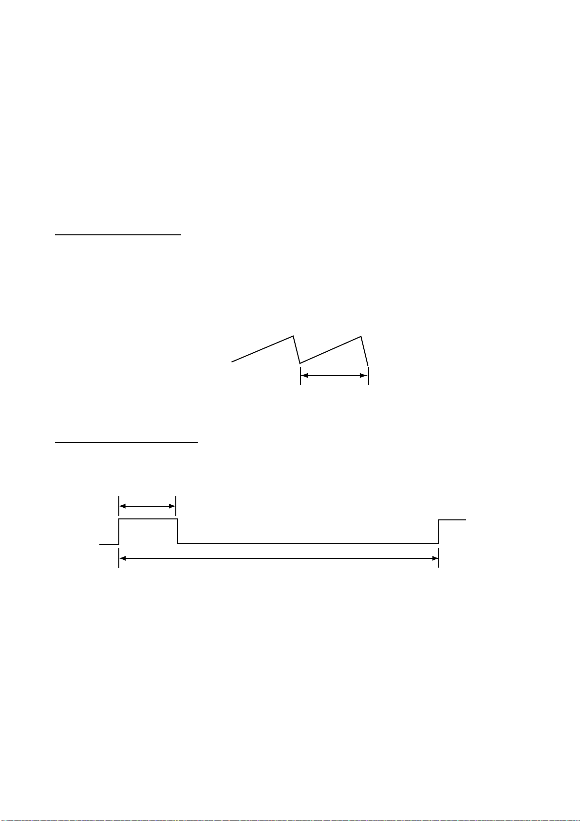
UNWY: Warning sign al for power-driven vessels underway. One 5-second blast at 120
second interval intervals.
5 s
120 s
Underway s ignal
1 s
14
Page 21

2. OPERATION
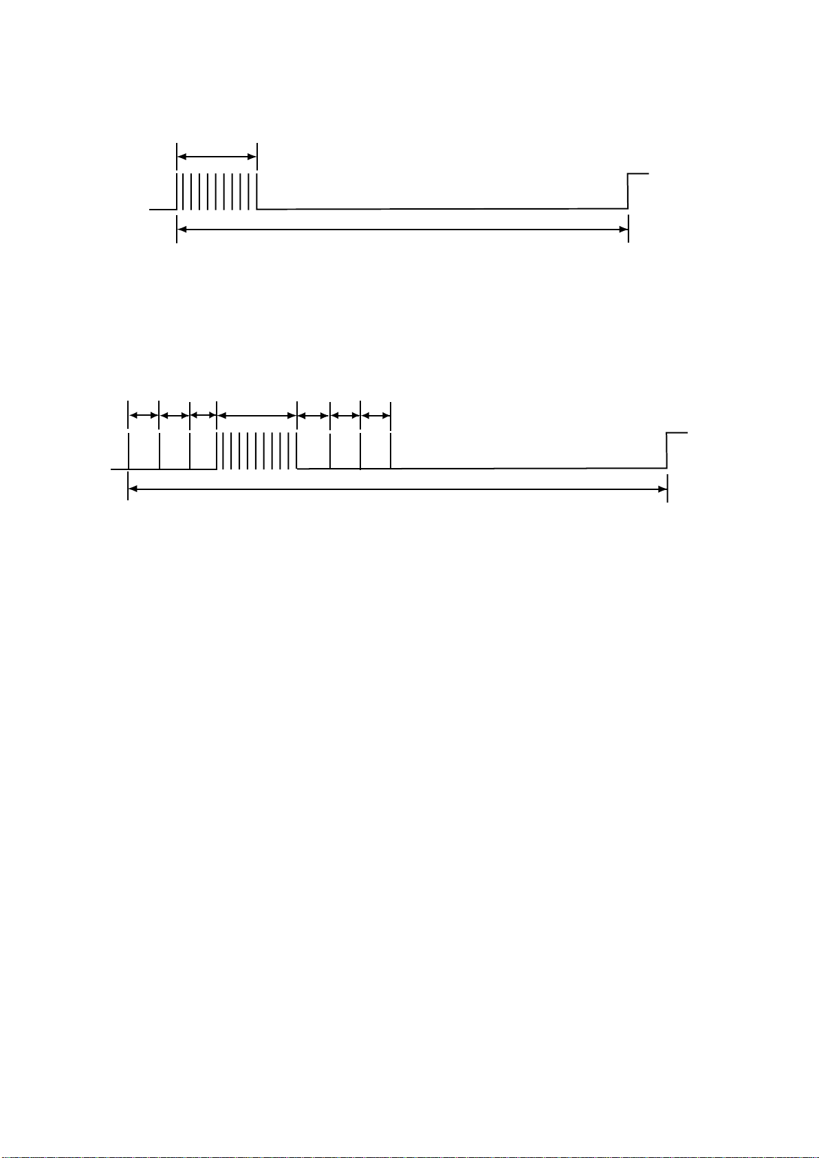
SAIL: Warning signal for sail boats, tug boats and tow boats und er way. One 3-second
blast, followed by one 2- s ec ond interval, one 1- s ec ond blast, one 2-second
interval and one 1-second blast. Repeated every 120 seconds.
1 s
2 s
2 s
3 s
1 s
120 s
Sailing signal
TOW: Warni ng s ignal for vessels und er tow. O ne 3-s ec ond blast, f ollow ed by one
2-second i nterval, one 1- s econd blast , one 2-se c ond interval , one 1-second blast,
one 2-secon d interval , and one 1-second blast. Repeated ev er y 120 seconds .
2 s
1 s
2 s
3 s
1 s
2 s
1 s
120 s
Tow ing signal
STOP : Warni ng s ignal for power - dr iven vessel that is stationary. Two 3-second blasts,
with a 2-second interval between each blast, repeated every 120 seconds.
3 s
2 s
3 s
120 s
St op s ignal
15
Page 22
2. OPERATION
ANCH: Warning si gnal for vessels at anchor. A rapidly ringing bell tone sounds for a
duration of 5 s ec onds, repe ated at an interval of 60 seconds.
5 s
60 s
Anchor signal
AGND: Wa r ning signal for vessels agroun d. Two bell tones of 0. 5 s ec onds, a bell tone of
1 second followed by a r apidly ringing bell t one for a dur ation of 5 seconds,
followed by a bell tone of 2 seconds and 0. 5 s econds. Re peated onc e every 60
seconds.
0.5 s 0.5 s 1 s 5 s 2 s 0.5 s 0.5 s
60 s
Aground si gnal
Sounding a manual warning signal
1. Press the [Hail Select ] key until the indicator lights for the desir ed hor n s peaker(s). If no
selection is made, “ B OTH” will be aut om atically selected when a war ning signal is
initiated.
2. Press the [Upper S ignal Sel ec t] key to select YELP or pr es s the [Low er S ignal Select]
key to select MAN. The indic ator begins flashing for the des ired signal.
3. Press the [FUNC] k ey to act ivate the warning signal. The indicator st ops flashi ng and
lights steadily.
4. Press the PTT switc h on the microphone t o s ound the warning si gnal. Each ti m e the
PTT sw itch is pressed, the warning signal will sound until the PTT swit c h is r eleased.
When the PTT swit c h is released the equipment will r eturn to the li s ten mode. Adj us t the
[LISTEN VOL] control if necessar y.
5. To temporarily interrupt manual si gnals wit h voic e transmiss ions do the following:
1) Press the [Hail Select] key. The indicator for the chosen signal flashes to indicate the
signal is still selected, but not active.
2) Press the PTT switch on the microphone and speak into the microphone. Your voice will
sound to all st a ti o ns .
3) Release the PTT switch again to return to manual warning signals.
16
Page 23

2. OPERATION
Sounding an automatic warning signal
1. Press the [Hail Select ] key until the indicator lights for the desir ed hor n s peaker(s). If no
selection is made, “ B OTH” will be aut om atically selected when a war ning signal is
initiated.
2. Press the [Upper S ignal Sel ec t key] to select UNWY, SAIL or TOW or press the [Lower
Signal Select] k ey to select STOP, A NCH or AGND until the indi c ator flashes f or the
desired si gnal.
3. Press the [FUNC] k ey to act ivate the automat ic warning signal . The indicator s tops
flashi ng and lights and then the signal is s ounded from the s elected horn speaker(s) .
4. To temporarily interr upt automati c s ignals with voice trans m issions , press the [FUNC]
key. The indicator for the chos en s ignal flashes to indicate the signal i s still select ed, but
not active.
5. Press the PTT switc h on the microphone and speak i nto the micr ophone. Your voice
sounds from the chosen horn speaker(s ) .
6. Release the PTT switch and press t he [FUNC] key again to return to automat ic warning
signals.
7. To stop transmitting automatic warning signals, press the [FUNC] key followed by t he
[Hail S elect] key to r eturn to the standby mode.
Calling interc om statio ns while s ou n ding war nin g sig n als
Calling all intercom stations
1. While pressing and holding down the [ Hail Select ] key, press the PTT sw itch. All
intercom indicator s flash.
2. Press the PTT switc h on the microphone and speak i nto the micr ophone.
3. After speaking, releas e the PTT switch and then the [Hail Select ] key to retur n to the
chosen warning signal.
Calling a specific intercom station
1. Press the [Intercom Select] key until the indi c ator lights on the desir ed intercom stati on.
A short tone sounds from t he s elected intercom one sec ond after choosing a stati on.
2. Press the PTT switc h on the microphone and speak i nto the micr ophone.
3. Release the PTT switch to list en to the reply from the select ed intercom station. If
necessary, adjust the li s tening volume with the [LISTEN VOL] control.
4. After you have finished your conversation, press the [Hail Select] key to ret urn to the
standby mode. Signal activi ty on the selec ted horn speaker will be r es tored.
17
Page 24

2. OPERATION
2.11 Transmitting the Auxiliary Signal
Transmitting the auxiliary signal over all speakers
An audio signal from an ext ernal audi o s ourc e can be transmitted thr ough the equipment
via the AUX input connector on the rear p anel.
1. In the standby m ode, press the [A UX ] key. The signal from the external AF source (radio,
CD player, etc.) sounds from all intercom stations and any connect ed horn speaker s .
Adjust t he output volume level di rec tly from the ex ternal input source.
2. To turn off the external AF signal, press the [A UX] key to ret ur n to the st andby mode.
Transmitting the auxiliary signal over all intercom stations
1. Press and hold t he [Inter c om S elect] key.
2. Press the [AUX] key.
Returning auxiliary transmission to standby mode
Press the [A UX] key tw ice.
2.12 Alarm Mode
The LH-3000 can operate as a burglar alarm by connecting an ex ternal, normal-open switch
to the ALRM terminal s on the r ear panel.
Both horn speak ers are sel ected automat ically when the al ar m m ode is enabled. If the
alarm is t ri gger ed, the volume output i s automatically set to maximum.
Enabling the alarm mode
1. Press and hold down the [Upper S ignal Sel ec t] key until the YELP indicat or flashes.
Note that you may li ght the MAN indicator (with the [ Lower Signal Select] key) instead of
the Y E LP indicat or.
2. Press the [FUNC] key unti l t he ALL, FWD, AFT and BOT H indicator s light. The YELP
indicat or goes off.
3. After approximately five minut es, the ALL, FWD, AFT and BO TH indicators go off. Then
the equipme nt goes into standby, lighting the BOT H indicator every four seconds t o
indicat e s tandby m ode.
See the next p age for procedure flow.
When an attempt is made to remove the Loud Hai ler
When an attempt is made to remove the Lo ud Hailer, the alarm sound is released through
both horn speakers at maximum volume. The alarm sounds f or two minutes followed by a
five-minut e r es t time. The BOT H indicator li ghts every four seconds during the sounding of
the alarm or t he five-minut e r es t period.
18
Page 25

2. OPERATION
Disabling the alarm mode
Press any k ey or switch ot her than the [AUX] or [DIM ] key, or turn off the power.
Enable alarm
Press the [Lower Signal
Select] key to flash
the YELP indicator.
Press the [FUNC] key.
ALL, FWD, AFT and BOTH indicators light.
YELP indicator goes off.
After 5 minutes
ALL, FWD, AFT and BOTH indicators go off.
BOTH indicator lights every four seconds.
STANDBY STATUS
(Alarm mode enabled)
An attempt is made
to remove the
Alarm sound is released through both horn
speakers at maximum volume.
Loud Hailer with
alarm mode active
Press any key except AUX or DIM,
or turn off the power.
Alarm set t ing/cancel flow
Silence/cancel alarm
19
Page 26

2. OPERATION
2.13 Siren Mode (for LH-3000-CG)
Enabling the siren mode
The si r en m ode, ac tivated by a sw itch connect ed to the burglar alarm t erm inal, f unc tions to
sound the warning signal (YELP ) from both horn s peak ers in the standby mode. To interrupt
the war ning signal to s peak , pr es s the PTT sw itch on the microphone and speak into it .
Communicati n g wit h inter com st ati o ns while in th e sir e n mode
You may c om m unicate wit h intercom stat ions in the sir en m ode. However, unlike the
standby mode, you must choos e intercom statio ns .
1. In the siren mode, pres s the [Intercom Selec t] key until the indicat or lights on the desired
intercom station. A fter a one-second delay, a short tone sounds from the sel ec t ed
intercom station.
2. Press the PTT switch on the m icrophone and speak into it.
3. Release the PT T switch to listen for a reply from the sel ec ted intercom station. If
necessary, adjust listening volume wi t h the [ LISTEN V OL] control.
4. After completing your c onversation, pr es s the [Hai l Select] k ey t o r eturn to the siren
mode.
Talking to ALL intercom stations while in the siren mode
You may talk to ALL intercom s tations. However, unl ike the standby mode, you must
choose intercom stations.
1. In the siren mode, pres s the [Intercom Selec t] key until the indicat or lights on the desired
intercom station.
2. Press and hold down the [Hail Select ] key, then press the P TT swit c h and talk into the
microphone.
3. After speaking, release the P T T swi t c h and then the [Hail Select] k ey to return to the
siren mode.
Disabling the siren mode
Turn off the siren mode sw itch, and t he LH- 3000-CG stops s ounding.
20
Page 27

3. MAINTENANCE, TROUBLESHOOTING
Periodic checks and maint enance are i mportant for maintaining performance. This chapter
contai ns m aintenance and troubles hooting instructions to be followed to obtai n optimum
performanc e and the longest possi ble life of the equipment.
WARNING
Do not open the equipment.
Only qualified personnel should work inside
the equipment.
3.1 Preventive Maintenance
General checks
Check the fol lowi ng m onthly.
Check all c abling. I f damaged, replac e.
Check connect ions. Retighten if necessary.
Measure the input voltage to be sure it is within the rated vol tage (13.6 V DC ±20%).
Cleaning
Dust or dirt should be removed from ext er ior surfaces wi th a soft, dry cloth. Do not us e
chemical -bas ed cleaners to clean the Loud Hailer – they c an r em ove paint and m ar k ings.
21
Page 28

3. MAINTENANCE, TRO UBLESHO OTING
3.2 Replacing the Fuse
The 6A f use ins ide the Loud Hailer protec ts it from reverse polarity and equipment faul t. If
the power c annot be turned on, the fuse may have blown. Have a qualified tec hnician check
the fuse.
WARNING
Use the proper fuse.
Use of a wrong fuse can result in damage
to the equipment or cause fire.
3.3 Troubleshooting
Below are s imple tr oubleshooting pr oc edures which the user m ay follow to try to res tore
normal oper ation. If normal operat ion cannot be r es tored, do not attempt to check inside
any unit . Any repair work is best left to a qualified techni c ian.
Troubleshooting table
If…
power cannot be turne d on check that the power cable is tightly connected.
fuse may have blown. Have a qu alified technician
check the fuse.
you cannot hear voice from an intercom
station
output volume is too low adjust the [HAIL VOL] control.
adjust the [LISTEN VOL] control.
Then…
22
Page 29

FURUNO
SPECIFICATIONS OF LOUD HAILER
LH-3000/LH-3000-CG
1 AUDIO OU T PUT
1.1 Hail speaker 30 W, 8 ohms
1.2 Intercom speaker 4.5 W, 4 ohms
1.3 External speaker 4.5 W, 4 ohms
1.4 Internal speaker 2.5 W, 4 ohms
2 INPUT IMPEDANCE
2.1 MIC impedance 600 ohms
2.2 Aux impedance 10K ohms
3 INPUT SENSITIVITY
3.1 MIC sensitivity -73 ±3 dB (0 dB=1V/µBar)
LH-3000/LH-3000-CG
3.2 Aux sensitivity 0 dBm ±3 dB (at 1 kHz)
4 DISTORTION FACTOR
4.1 Hail mode 10% (1 kHz 30 W)
4.2 Intercom mode 10% (1 kHz 2.5 W)
5 SIGNAL-TO-NOISE
5.1 Hail mode 60 dB (1 kHz)
5.2 Intercom mode 60 dB (1 kHz)
6 POWER SUPPLY
12 VDC, less than 5A, less than 280 mA (standby)
7 ENVIRONMENTAL CONDITIONS
7.1 Ambient temperature -15 to 55°C
7.2 Relative humidity 95% at 40°C
7.3 Waterproofing IPX5 (Front panel), IPX0 (Other)
8 COLOR
N3.0
9 SIREN MODE (LH-3000-CG)
Sounds warning signal in standby.
SP - 1 E5646S01C
Page 30

This page is intentionally left blank .
Page 31

1/1
A-1
Q'TY
1
1
1
1
05EB‑X‑9851
05EB‑X‑9851‑0
LH‑3000
DESCRIPTION/CODE№
TZ7300030A
OUTLINE
NAME
防振ゴム1
000‑149‑771
TZ7300031A
RUBBERCUSHION
防振ゴム2
000‑149‑772
E52‑00303‑*
図書 DOCUMENT
RUBBERCUSHION
型紙
000‑149‑157
OME‑56460‑*
TEMPLATE
取扱説明書
000‑149‑118
OPERATOR'SMANUAL
PACKING LIST
1
LH‑3000
000‑040‑004
1
DM‑2003
1
**
999‑999‑022
FORDM‑2003
3
**
999‑999‑023
3X10
**
999‑999‑024
FGMB6A125V
2
000‑147‑324
6X20SUS3041シュ
4
000‑802‑084
NAME OUTLINE Q'TYDESCRIPTION/CODE№
ユニット UNIT
ラウドヘイラ‑
LOUDHAILER
マイクセット MICROPHONESET
マイクロフォン
MICROPHONE
MICハンガー
MICROPHONEHANGER
+ナベタッピンネジ
+TAPPINGSCREW
ヒューズ
予備品 SPAREPARTS
FUSE
工事材料 INSTALLATIONMATERIALS
+トラスタッピンネジ
+TAPPINGSCREW
1.コ-ド番号末尾の[**]は、ダミーコードに付き、注文できません。
** THISCODECANNOTBEORDERED.
(略図の寸法は、参考値です。DIMENSIONSINDRAWINGFORREFERENCEONLY.)
Page 32
工事材料表
A-2
INSTALLATIONMATERIALS
番号
NO.
1
名 称
NAME
2対ケーブル *20M*
2PTWISTEDPAIRCABLE
略 図
OUTLINE
CODENO.
TYPE
型名/規格
DESCRIPTIONS
CO‑SPEVV‑SB‑C0.2X2P
CODENO.
000‑120‑794
数量
Q'TY
1
05EB‑X‑9402
選択
TOBESELECT
‑0
用途/備考
REMARKS
1/1
2対ケーブル *15M*
2
2PTWISTEDPAIRCABLE
2対ケーブル *10M*
3
2PTWISTEDPAIRCABLE
2対ケーブル *5M*
4
2PTWISTEDPAIRCABLE
CO‑SPEVV‑SB‑C0.2X2P
CODENO.
CO‑SPEVV‑SB‑C0.2X2P
CODENO.
CO‑SPEVV‑SB‑C0.2X2P
CODENO.
000‑120‑793
000‑120‑792
000‑111‑680
選択
TOBESELECT
1
選択
TOBESELECT
1
選択
TOBESELECT
1
05EB‑X‑9402
FURUNO ELECTRIC CO .,LTD.
(略図の寸法は、参考値です。 DIMENSIONSINDRAWINGFORREFERENCEONLY.)
Page 33
フラッシュマウントキット
A-3
FLUSHMOUNTKIT.
LH‑3020
CODENO.
TYPE
000‑149‑112
05EB‑X‑9401
‑0
1/1
番号
NO.
蝶ナット
1
WINGNUT
蝶ボルト
2
WINGSCREW
+トラスネジ
3
SCREW
フラッシュマウント金具
4
FLUSHMOUNTINGPLATE
名 称
NAME
略 図
OUTLINE
型名/規格
DESCRIPTIONS
M4SUS3042シュ
CODENO.
M4X35SUS3042シュ
CODENO.
M6X12SUS304
CODENO.
TZ7300012A
CODENO.
999‑999‑028
999‑999‑027
999‑999‑026
999‑999‑025
数量
Q'TY
用途/備考
REMARKS
(*)
4
(*)
4
(*)
2
(*)
2
注記:(*)は、ダミーコードに付き、注文できません。
* THISCODECANNOTBEORDERED.
(略図の寸法は、参 考値です。 DIM ENS IO NS IN DR AW ING F OR RE FER EN CE ON LY. )
05EB‑X‑9401
FURUNO ELECTRIC CO .,LTD.
Page 34
Takahashi T.
Y.Hatai
Yosh
itoshi
Hatai
電子署名
者:
Yoshitoshi
Hatai
DN:
cn=Yoshit
oshi
Hatai,
o=Furuno,
c=JP
日付:
2004.01.2
3
11:29:48
+09'00'
署名は無効で
す
D-1
Page 35

Takahashi T.
Y.Hatai
Yosh
itoshi
Hatai
電子署名
者:
Yoshitoshi
Hatai
DN:
cn=Yoshit
oshi
Hatai,
o=Furuno,
c=JP
日付:
2004.01.2
3
11:29:48
+09'00'
署名は無効で
す
D-2
Page 36
Takahashi T.
Y.Hatai
Yosh
itoshi
Hatai
電子署名
者:
Yoshitoshi
Hatai
DN:
cn=Yoshit
oshi
Hatai,
o=Furuno,
c=JP
日付:
2004.01.2
3
11:29:48
+09'00'
署名は無効で
す
D-3
Page 37
Y.Hatai
D-4
Page 38
*1
Y. Hatai
S-1
*1
*1
*3
*3
*3
LH‑3010
インターコムスピーカ
INTERCOM SPEAKER
LH‑3010
インターコムスピーカ
INTERCOM SPEAKER
LH‑3010
インターコムスピーカ
INTERCOM SPEAKER
43
*1
J.B.
*5
RED
BLK
BLK
BRN
P
P
*3 CO‑SPEVV‑SB‑C 0.2X2P MAX 20m
2345678
1
J2
SP1
0V1
CAL1
*5
BRN
*3 CO‑SPEVV‑SB‑C 0.2X2P MAX 20m
*1
*1
RED
BLK
P
CAL2
J.B.
BLK
P
SP2
J.B.
*5
BRN
RED
BLK
BLK
P
P
*4
*4
*3 CO‑SPEVV‑SB‑C 0.2X2P MAX 20m
9
SP3
0V2
0V3
CAL3
*3
ALARM SENSOR
LH‑3010
SIREN MODE SWITCH(LH‑3000‑CG)
インターコムスピーカ
INTERCOM SPEAKER
*1
J.B.
*5
BRN
RED
BLK
P
P
*3 CO‑SPEVV‑SB‑C 0.2X2P MAX 20m
J3
123456789
SP4
CAL4
INPUT FROM
BLK
*1
*1
TTYCS‑1
TTYCS‑1
0V
AUX
0V4
ALARM
EXT. AUDIO SOURCE
0V
MICROPHONE
LH‑3000
ラウドヘイラー
相互結線図
LOUD HAILER
BRN
BLK
BLK
TITLE
名称
RED
MIC
P
P
*3 CO‑SPEVV‑SB‑C 0.2X2P, MAX 5m
10
11
0V
0V
MIC
PTT
FG
NC
NC
DM‑2003
E. MIYOSHI
TAKAHASHI. T
INTERCONNECTION DIAGRAM
NAME
C5646‑C01‑D
NC
AG
MIC
PTT
GND
1234567812
DRAWN
MAY 25, '04
CHECKED
APPROVED
DWG.No.
*2
LOUD HAILER
LH‑3000
GND
EXT. SPEAKER
J4
*1
TTYC‑1
2
FWD+
FWD‑
AFT‑
+13.6V
12345
J1
*1
DPYC‑1.5, MAX 7.5m
1
13.6 VDC
A
AFT+
‑13.6V
6
*1
*1
DPYC‑1.5
DPYC‑1.5
Forward Horn
*1
After Horn
*1
*4
IV‑1.25
B
φ3.5 PLUG
注記
*1)現地手配。
外部スピーカ 8Ω
*2)コネクタは工場にて取付済み。
*1
EXTERNAL SPEAKER
*3)オプション。
*4)ケーブルのあじろがい装にアース線を
JBとLH‑3010間は1m以下にすること。
DISTANCE BETWEEN LH‑3000 AND JB SHALL BE 20m OR LESS.
DISTANCE BETWEEN JB AND LH‑3010 SHALL BE 1m OR LESS.
CONNECT CABLE FROM LH‑3010 DIRECTLY TO LH‑3000.
USE JUNCTION BOX(JB).
2m OR LESS:
このアース線は放熱板にショートさせないこと。
ハンダ付けしてアース端子に接続。
*5)LH‑3000とLH‑3010間:
(2m以下の場合)LH‑3010からのケーブルを直接LH‑3000に接続すること。
(2mを超える場合)接続箱(JB)を使用し、LH‑3000とJB間は20m以下、
NOTE
*1: LOCAL SUPPLY.
*2: CONNECTOR PLUGS FITTED AT FACTORY.
*3: OPTION.
GREATER THAN 2m:
DO NOT SHORT THE DRAIN WIRES ON THE HEAT SINK.
*5: CABLING BETWEEN LH‑3000 AND LH‑3010:
*4: SOLDER DRAIN WIRE TO ARMOR OF CABLE AND CONNECT IT TO EARTH TERMINAL.
C
Page 39

Page 40
9-52 Ashihara-cho,9-52 Ashihara-cho,
A
A
*
00014911811
**00014911811
*
*
00014911811
**00014911811
*
*
OME
56460
B
00
**OME
56460
B
00
**OME
56460
B
00
**OME
56460
B
00
*
Nishinomiya 662-8580, JAPANNishinomiya 662-8580, JAPAN
Telephone :Telephone : 0798-65-21110798-65-2111
FaxFax 0798-65-42000798-65-4200
::
The paper used in this manual
is elemental chlorine free.
FURUNO Authorized Distributor/DealerFURUNO Authorized Distributor/Dealer
ll rights reserved.
ll rights reserved.
Pub. No.Pub. No. OME-56460OME-56460
(( DAMIDAMI ))
LH-3000LH-3000
Printed in JapanPrinted in Japan
FIRST EDITION :FIRST EDITION : FEB.FEB. 20042004
BB ::MAY.MAY. 26, 200526, 2005
* 0 0 0 1 4 9 1 1 8 1 1 ** 0 0 0 1 4 9 1 1 8 1 1 *
* O M E 5 6 4 6 0 B 0 0 ** O M E 5 6 4 6 0 B 0 0 *
 Loading...