

Page 1

INTERFACE UNIT
IF-2500
(TENI, 0307)
PUB. No. OMC-43421-A1
IF-2500
Page 2
SAFETY INSTRUCTIONS
CAUTION
The mounting location should satisfy
the following conditions:
Sparate from radio transmitter, radar,
direction finder (at least 3m).
Locate the equipment away from air
conditioner vents.
Keep the equipment out of direct
sunlight.
Vibration should be minimal.
The location should be free of water
spray.
CAUTION
Observe the following compass safe
distances to prevent deviation of a
magnetic compass:
Standard
compass
IF-2500
Turn off the power switch at the
switchboard before beginning the
installation.
1.40 m 0.95 m
Steering
compass
i
Page 3

TABLE OF CONTENTS
Overview...............................................................................................................1
Installation materials...........................................................................................1
Spare parts...........................................................................................................1
Cables...................................................................................................................2
Mounting............................................................................................................... 2
Grounding ............................................................................................................2
Selection of output data format.......................................................................... 2
Cable fabrication .................................................................................................2
Maintenance.........................................................................................................5
SPECIFICATIONS
PACKING LIST
OUTLINE DRAWING
INTERCONNECTION DIAGRAM
ii
Page 4
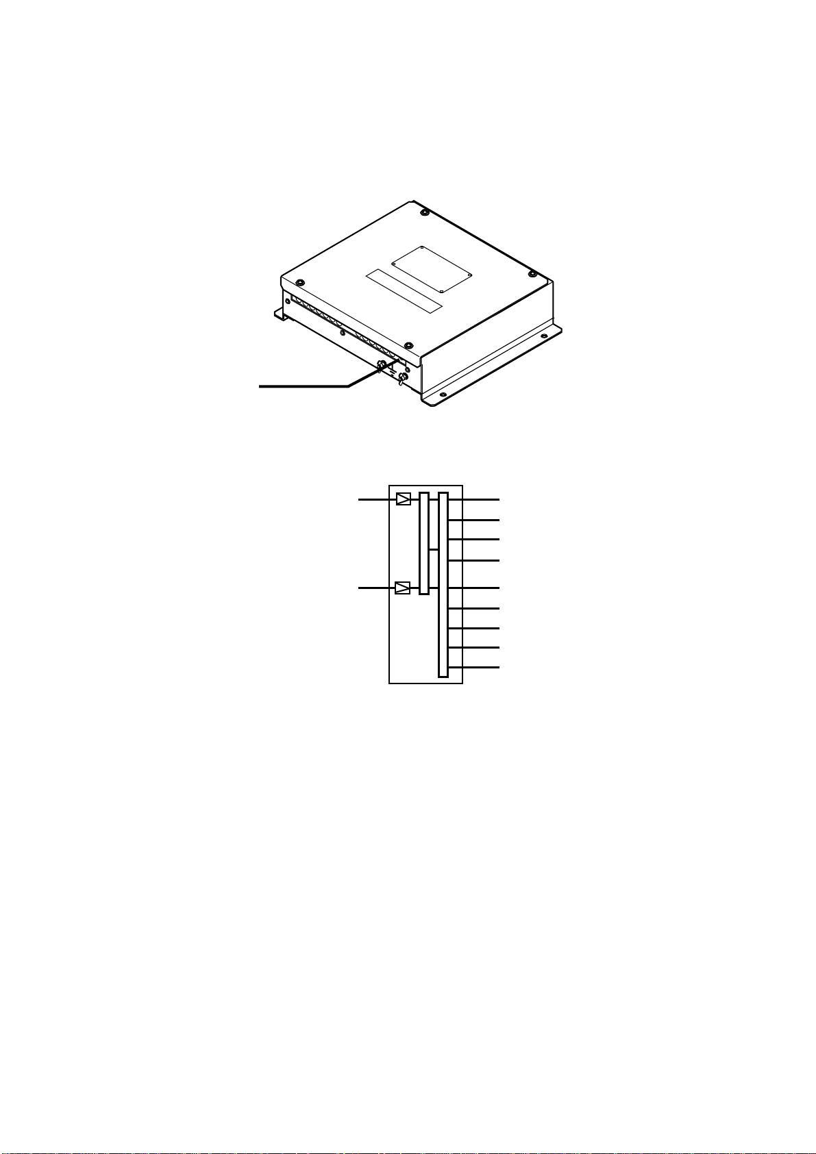
Overview
The interface for the dual GPS navigator receives data from two GPS navigators and chooses
one to output in accordance with priority order. Output data is converted to NMEA cur r ent loop,
IEC 61162-1 or contact signal and output.
12-24 VDC
Outputs data in accordance
with priority order
Input 1
(GPS navigator)
Input 2
(GPS navigator)
Output 1
Output 2
Output 3
Output 4
Output 5
Output 6
Receiving Error Alarm
Cross Track Error Alarm
Arrival Alarm
1
Page 5

Mounting
This unit does not have power switch. If you
do not connect the IF-2500 to power
switchboard or circuit breaker, install an
external power switch (local supply), locating
it near the IF-2500.
Selection of output data format
The output data format is selectable by
changing a jumper block; A for IEC61162-1
and B for NMEA. For example, to select
NMEA for J4, change the jumper block from A
to B on JP401 and JP402. Do the same on J5
thru J9.
Factory setting
Output Jumper
J4 JP401/JP402
J5 JP501/JP502
J6 JP601/JP602
J7 JP701/JP702
J8 JP801/JP802
J9 JP901/JP902
IEC61162-1
(A)
!
!
!
!
!
Current
loop
(B)
!
• All dimensions in millimeters.
• For added support, use nuts, bolts and
washers instead of woodscrews.
• Leave sufficient space at the sides and rear
of the unit for maintenance and servicing.
Grounding
To prevent mutual interface, run a ground
wire between the earth terminal on the unit
and ship’s superstructure.
Cable fabrication
Use the following cables (Japan Industrial
Standard cables) or the equivalents.
TTYCS-1 (Twisted pair cable)
Current loop or IEC 61162-1 signal
Armor
Sheath
Shield
φ = 10.1 mm
CO-SPEVV-SB-C 0.2x2P
φ = 10.5 mm
Conductor
S = 0.75 mm
φ = 1.11 mm
Current loop or IEC 61162-1 signal
Conductor
S = 0.2 mm
φ = 0.6 mm
2
Vinyl sheath
Armor
Sheath
Shield
2
2
Page 6

Fabrication of CO-SPEVV-SB-C 0.2X2P
75 mm
(Supplied)
Earth cable
3 mm
15 mm
3 mm
Twist and solder
35 mm
Sheath
33 mm
Shield
28 mm
Cut unused cores and solder them to shield.
15 mm
Heat shrink tube
Armor
30 mm
Fix the cable with
the cable clamp
at this location.
Heat shrink tube
How to fabricate the signal cable
3
Page 7

JP801JP701JP601JP501JP901JP401
S1
10-35V
J1
Power
FUSE
0.5A
Alarm output 3
J12
Alarm output 2
J11
Alarm output 1
J10
14P0285
JP802
JP702JP602JP502JP402JP902
B
A
B
A
B
A
B
A
B
A
A
B
CR10
CR9CR8CR7CR6CR4CR3CR2
B
A
B
A
B
A
B
A
A
B
B
A
J8
J7
J6
J5
J4
J9
Output port 5
Output port 4
Output port 3
Output port 2
Output port 1
Output port 6
Input port 2
J3
Input port 1
J2
Alarm output 1 Arrival Alarm
Alarm output 2 Cross Tr ack Error Alarm
Alarm output 3 Receiving Error Alarm
Alarm output normal closed type
Normal Relay contact is closed.
Abnormal Relay contact is open.
Turns the power
Relay contact is open.
off
Jumper
Parts location
A: IEC61162-1
B: Current loop
LEDs (Normal status)
CR6 Blinks every second.
CR7 Off.
CR8 Off.
CR9 Lights when Input port 1 has
priority.
CR10 Lights when Input port 2 has
priority.
4
Page 8

Maintenance
Self test 1
The unit performs an internal self-check in
the following sequence each time power is
turned on.
1. LEDs CR7 to CR10 blink twice every 2
seconds.
2. ROM and RAM are tested.
3. LED CR6 blinks every second for normal
operation. If an error is detected during
the test, the corresponding LED is turned
on.
• When CR7 is on, ROM is defective.
• When CR8 is on, RAM is defective.
Self test 2
The test requires an external loop to check
I/O. Follow the steps below to carry out the
test.
1. Set the DIP switch #4 of S1 to the ON
position.
2. Temporarily disconnect input and output
connectors J2 and J4.
3. Construct a pair of short connector
assemblies as below.
For J4, J5, J6 ,J7 and J8
RS422_OUT_A
RS422_OUT_B
GND
For J9
RS422_OUT_A
RS422_OUT_B
GND
1
2
3
NC NC
4
1
2
3
NC
4
NC
5
XH4P
XH5P
XH6P
XH6P
Short connector assy
4. Connect the XH6P-XH4P short connector
assy. between J2 and J4.
5. Confirm that each LED lights according
to equipment status as follows:
1
2
3
4
5
6
1
2
3
4
5
6
J2
NC
NC
RD_H
RD_C
GND
J2
NC
NC
RD_H
RD_C
NC
GND
CR2 Lights when receiving NMEA data
from J2.
CR4 Lights when sending NMEA data
to J4 thru J9.
CR6 Blinks every second.
CR7 Lights when ROM error is
detected.
CR8 Lights when RAM error is
detected.
CR9 Lights when SIO error is detected.
CR10 Normally off.
5. Remove the connector from J4 and plug
it into J5, J6, J7 and J8 successively,
confirming that CR2 and CR9 light as
below for each port. Then, remove the
XH6P-XH4P short connector assy., plug
in the XH6P-XH5P short connector assy.
between J2 and J9, and confirm that CR2
and CR9 light as below.
CR2 Lights when receiving NMEA data
at J2.
CR9 Lights when SIO error is detected.
6. Remove the XH6P-XH5P short
connector assy. Plug in the XH6P-XH4P
short connector assy. between J3 and J4,
J5, J6, J7 and J8 successively. Confirm
that LEDs light or blink as below.
Remove the XH6P-XH4P short
connector assy., plug in the XH6P-XH5P
short connector assy. between J3 and J9
and confirm that the LEDs light or blink
as below.
CR3 Lights when receiving NMEA data
at J3.
CR4 Lights when sending NMEA data
to J4 thru J9.
CR6 Blinks every second.
CR9 Lights when SIO error is detected.
The relay contact signal output is turned on
and off alternately every second during the
test.
Fuse replacement
If the fuse blows, find the cause of the
problem before replacing it. Do no use a fuse
rated more than 0.5A, since it may cause
more serious damage to the equipment.
5
Page 9

FURUNO
SPECIFICATIONS OF INTERFACE UNIT
IF-2500
This equipment is used for dist ribution of navaids data from navigation eq uipment. It provides
six outputs each from two independent inputs. Alarm sig nal is also available to distribute three
outputs from two independent inputs.
1. Port Input: 2 ports (IEC61162-1)
Output: 6 ports (IEC61162- 1 or Cur rent loop)
Alarm signal Output: 3 port s ( Relay contact )
2. Alarm signal Receiving Error Alarm, Cross T rack Error Alarm, Arrival Alarm
3. Rated voltage/Current 12-24 VDC: 0.16-0.08 A
4. Coating Color 2.5GY 5/1.5 Newtone No.5
5. Ambient Temperature -15 to 55℃
6. Relative Humidity 95%RH(40℃)
7. Water proofing IPX0
SP-1 E4408S01C
Page 10

Page 11

1/1
Q'TY
3
1
(*1)
1
(*1)
1
14CL‑X‑9851
14CL‑X‑9851‑1
DESCRIPTION/CODE№
XH3P‑002
OUTLINE
NAME
XHコネクタ組品
000‑000‑994
VCTF1.25X2C*3M*/VH2P
XHCONNECTORASSY.
電源ケーブル組品
000‑000‑995
3X0.25クロ*1.00M*
POWERCABLEASSY.
スミチューブF(Z)
HEAT‑SHRINKTUBE
000‑568‑172
10X0.25クロ*0.5M*
スミチューブF
000‑123‑379
HEAT‑SHRINKTUBE
IF‑2500
IF‑2500IF‑2500
IF‑2500
IF‑2500
UNITUNIT
UNIT
1
(*1)
000‑000‑999
3
SP14‑01100SP14‑01100
SP14‑01100
FGMB0.5AAC125V
SPAREPARTSSPAREPARTS
SPAREPARTS SP14‑01100
CP14‑06300CP14‑06300
CP14‑06300
000‑114‑994
MJ‑A6SPF0012‑100
INSTALLATIONMATERIALSINSTALLATIONMATERIALS
INSTALLATIONMATERIALS CP14‑06300
1
64S4071
4
000‑133‑817
4X16SUS3041シュ
2
000‑802‑080
XH6P‑002
(*1)
000‑000‑991
XH5P‑002
1
(*1)
000‑000‑992
XH4P‑002
5
(*1)
000‑000‑993
NAME OUTLINE Q'TYDESCRIPTION/CODE№
ユニット
ユニットユニット
PACKING LIST
PACKING LISTPACKING LIST
PACKING LIST
ユニット UNIT
インタ‑フェイスユニット
INTERFACEUNIT
予備品
予備品予備品
予備品 SPAREPARTS
ヒューズ
FUSE
工事材料
工事材料工事材料
工事材料 INSTALLATIONMATERIALS
ケーブル組品MJ
CABLEASSY.
+トラスタッピンネジ
+TAPPINGSCREW
XHコネクタ組品
XHCONNECTORASSY.
XHコネクタ組品
XHCONNECTORASSY.
XHコネクタ組品
XHCONNECTORASSY.
1.(*1)印のユニット及び部品コードは架空コードに付き注文用には使用できません。
(*1)Code numbers are not allowed to order as dummy code.
(略図の寸法は、参考値です。DIMENSIONSINDRAWINGFORREFERENCEONLY.)
(略図の寸法は、参考値です。DIMENSIONSINDRAWINGFORREFERENCEONLY.)(略図の寸法は、参考値です。DIMENSIONSINDRAWINGFORREFERENCEONLY.)
(略図の寸法は、参考値です。DIMENSIONSINDRAWINGFORREFERENCEONLY.)
Page 12

123
Takahashi T.
Takahashi T.
インターフェイスユニット
INTERFACE UNIT
IF‑2500
A
12‑24VDC
VCTF1.25x2C/VH2P,3m,φ7.4
航法装置
NAVIGATOR
データ入力
IEC61162‑1
優先順位 (Priority): J2 > J3
航法装置
NAVIGATOR
CO‑0.2x2P OR
TTYCS‑1 *1
DATA INPUT
CO‑0.2x2P OR
TTYCS‑1 *1
P
P
P
J1(VH2P)
1
2
1
2
3
4
5
6
1
2
3
4
5
6
DC+
DC‑
J2(XH6P)
NC
NC
RD‑H
RD‑C
NC
GND
J3(XH6P)
NC
NC
RD‑H
RD‑C
NC
GND
B
TD‑H/TD‑B
*2
TD‑C/TD‑A
TD‑H/TD‑B
*2
TD‑C/TD‑A
TD‑H/TD‑B
*2
TD‑C/TD‑A
TD‑H/TD‑B
*2
TD‑C/TD‑A
J4(XH4P)
NC
GND
J5(XH4P)
NC
GND
J6(XH4P)
NC
GND
J7(XH4P)
NC
GND
1
2
3
4
1
2
3
4
1
2
3
4
1
2
3
4
CO‑0.2x2P OR
TTYCS‑1 *1
P
CO‑0.2x2P OR
TTYCS‑1 *1
P
CO‑0.2x2P OR
TTYCS‑1 *1
P
CO‑0.2x2P OR
TTYCS‑1 *1
P
出力
OUTPUT
IEC61162‑1/
CURRENT LOOP
出力
OUTPUT
IEC61162‑1/
CURRENT LOOP
出力
OUTPUT
IEC61162‑1/
CURRENT LOOP
出力
OUTPUT
IEC61162‑1/
CURRENT LOOP
C
注記
*1)造船所手配。
*2)内部の設定で切替え。
D
J8(XH4P)
TD‑H/TD‑B
*2
TD‑C/TD‑A
GND
J9(XH5P)
TD‑H/TD‑B
*2
TD‑C/TD‑A
GND
J10(XH3P)
ALARM‑OUT1‑H
ALARM‑OUT1‑C
ALARM‑OUT2‑H
ALARM‑OUT2‑C
ALARM‑OUT3‑H
ALARM‑OUT3‑C
GND
J11(XH3P)
GND
J12(XH3P)
GND
アース銅板 *1
COPPER STRAP
CO‑0.2x2P OR
1
2
3
NC
4
1
2
3
NC
4
NC
5
1
2
3
1
2
3
1
2
3
TTYCS‑1 *1
P
CO‑0.2x2P OR
TTYCS‑1 *1
P
CO‑0.2x2P OR
TTYCS‑1 *1
P
CO‑0.2x2P OR
TTYCS‑1 *1
P
CO‑0.2x2P OR
TTYCS‑1 *1
P
出力
OUTPUT
IEC61162‑1/
CURRENT LOOP
出力
OUTPUT
IEC61162‑1/
CURRENT LOOP
アラーム出力(接近警報)
ALARM OUTPUT (ARRIVAL)
アラーム出力(オフトラック)
ALARM OUTPUT (OFF TRACK)
アラーム出力(受信不良)
ALARM OUTPUT (RECEIVING ERROR)
DRAWN
CHECKED
APPROVED
SCALE
DWG.No.
NOTE
*1. SHIPYARD SUPPLY.
*2. SELECT CURRENT LOOP OR IEC61162‑1 BY INNER SETTING.
CO‑0.2x2P: CO‑SPEVV‑SB‑C 0.2x2P,φ10.5
31 July '03
H.MAKI
MASS
kg
C4342‑C02‑ A
TITLE
IF‑2500
名称
インターフェイスユニット
相互結線図
NAME
INTERFACE UNIT
INTERCONNECTION DIAGRAM
 Loading...