

Page 1

INTERFACE UNIT
Back
IF-2300
Page 2

Page 3

Record of revision
Rev D:
Nov 2000
Prog No. 004
(1450132 004)
since production in
December 1999.
More detail is added to clarify the use of 2 input ports as below:
RD1: VBW/VTG (Log),
RD2: HDT or other data, e.g. MTW , DPT, DBT
Position: Direct to the associated radar
TD1-3: Compound data outputs
Introduction; the following is added: One of particular applications is to receive a speed
data and either heading or depth data and supply the compound data to radar FR-21x5 or
FR/FAR-28x5 Series.
2 - Functional overview. Priority related description is deleted.
Description for overflow is changed.
Page 4

CONTENTS
SPECIFICATIONS OF IF-2300 .................................................................................................................... 1
INTRODUCTION.......................................................................................................................................... 2
1 OPERATION .......................................................................................................................................... 2
2 FUNCTIONAL OVERVIEW..................................................................................................................... 2
3 MAINTENANCE ..................................................................................................................................... 3
3.1 Regular check ...................................................................................................................................... 3
3.2 Self-test................................................................................................................................................ 3
4 INSTALLATION ..................................................................................................................................... 5
4.1 General considerations for placement................................................................................................... 5
4.2 Mounting .............................................................................................................................................. 5
5 ADJUSTMENT ....................................................................................................................................... 7
5.1 Setting DIP switch S1........................................................................................................................... 7
PARTS LOCATION ..................................................................................................................................... 8
PARTS LIST ................................................................................................................................................ 8
DIAGRAMS
Page 5

SPECIFICATIONS OF IF-2300
A
Connection port 2 inputs
3 outputs: Compound data
Data sentence IEC 61162-1, NMEA 0183 (Version 1.5/2.0), or other format
Data rate 4800 baud
Operation No operator control after proper installation.
Power supply 12 - 24 VDC, 2 W max., 0.15 - 0.08 A
Physical data 150W x 180H x 45D (mm), 0.5 kg
Coating Light gray (2.5GY5/1.5 Newtone No. 5)
Equipment class To be installed in Protected Area
Equipment list Interface unit IF-2300 1 set
Installation materials CP14-04500 1 set
Spare parts SP14-01100 1 set
Compass safe distance Minimum distance from magnetic compass
Standard compass 0.50 m
Steering compass 0.40 m
ll incoming data is automatically conditioned and put through the
output ports.
This equipment is designed, produced and documented by FURUNO ELECTRIC CO., LTD.
which is certified to ISO 9001 standards by the Lloyds’ Register of Quality Assurance
System.
-1-
Page 6
INTRODUCTION
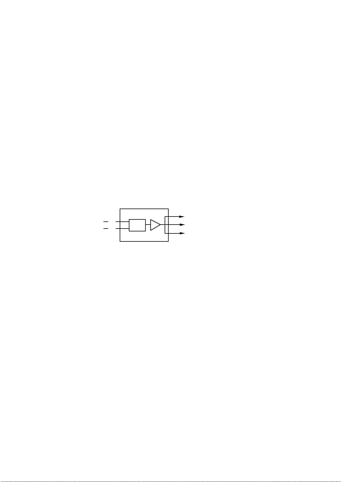
The Furuno interface unit IF-2300 receives digital data from 2 types of sensors or equipment and
transmits them to other equipment through 3 output ports. It handles any data format as well as
IEC 61162-1 sentences. One application is to receive speed data and either heading or depth data
and supply the data to radar series FR-21x5 or FR/FAR-28x5.
1 OPERATION
The IF-2300 does not need any user operation except for turning on or off the power switch. The
power switch can be a ship’s switchboard or a small dedicated switch. The unit can be left
energized at all times whether the associated equipment is in use or not.
2 FUNCTIONAL OVERVIEW
The IF-2300 receives any data written in sentence format of IEC 61162-1 edition 1 or NMEA 0183
Version 1.5/2.0 or others. Two Receive Data are mixed in the IF-2300 and the compound data is
outputted through three output ports. One example of applications is to feed LAT/LON and wind
data to one input port of the radar.
RD1
RD2
(a)
(b)
IF-2300
MIX
TD1:
TD2:
TD3:
(a) + (b)
(a) + (b)
(a) + (b)
CIF
Input and output data are in CIF format (FURUNO format). One record of input data is limitted up
to 300 bytes. Any bytes over that amount are invalid. Further, a record containing receive error is
also invalid.
IEC 61162-1
Input and output data are in IEC 61162-1 format. The P sentence (special code) is input/output.
Input port 1 takes priority over input port 2 when the same data is input to both. Note however that
the P sentence has no priority.
Priority is given to the input data sentences below. The P sentence is output preferentially.
AAM, APA, APB, BOD, BWC, RMA, RMB, RMC, WPL, XTE, ZDA
RD1: Receive data from an SDME (speedlog) in sentence of VBW or VTG
RD 2: Receive data in sentence of either HDT or other data e.g. MTW, DPT, DBT
Note: Position data (ex. Lat/Lon from a GPS navigator) is supplied directly to the FR/FAR-28x5
or FR-21x5 series radars.
TD1-3: Transmit data. Connect this output to Channel 1 of Radar FR-21x5 or FR/FAR-28x5 Series
Transmission rate: 4800 bps, Data batch is transferred from the receive buffer to the transmit
buffer at intervals of 500 ms. P sentences go straight through the transmit
buffer.
Overflow: The IF-2300 has the data receiving buffer, the capacity of which is 1600
characters (equivalent to 20 sentences) at inputs of RD1 and RD2. CR4
lights when the data amount exceeds this limit.
-2-
Page 7
3 MAINTENANCE
3.1 Regular check
Check all cables and ground monthly for tight connection.
3.2 Self-test
Start-up test
The following check is done automatically at each power-on.
ROM test: Checks the program area.
RAM test: Checks all memories.
Input data test: Checks the input data size.
LED Indicator
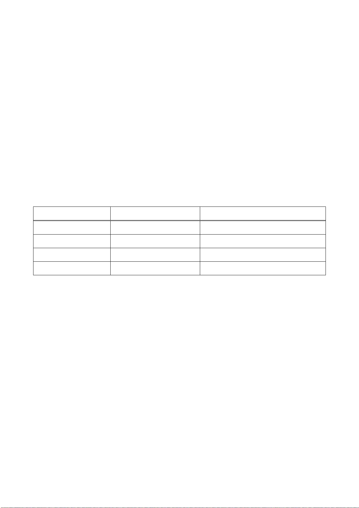
Error is warned with the state of LEDs, CR1 - 4.
LED No. State Condition
CR1 (Green) Blinks every second. Normal
CR2 (Red) ON ROM faulty
CR3 (Red) ON RAM faulty
CR4 (Red) ON Input buffer overflowing
Overflow: If data into RD1 and RD2 exceeds a total of 1600 characters (equivalent to 20
sentences), CR4 lights in red.
-3-
Page 8
Test mode
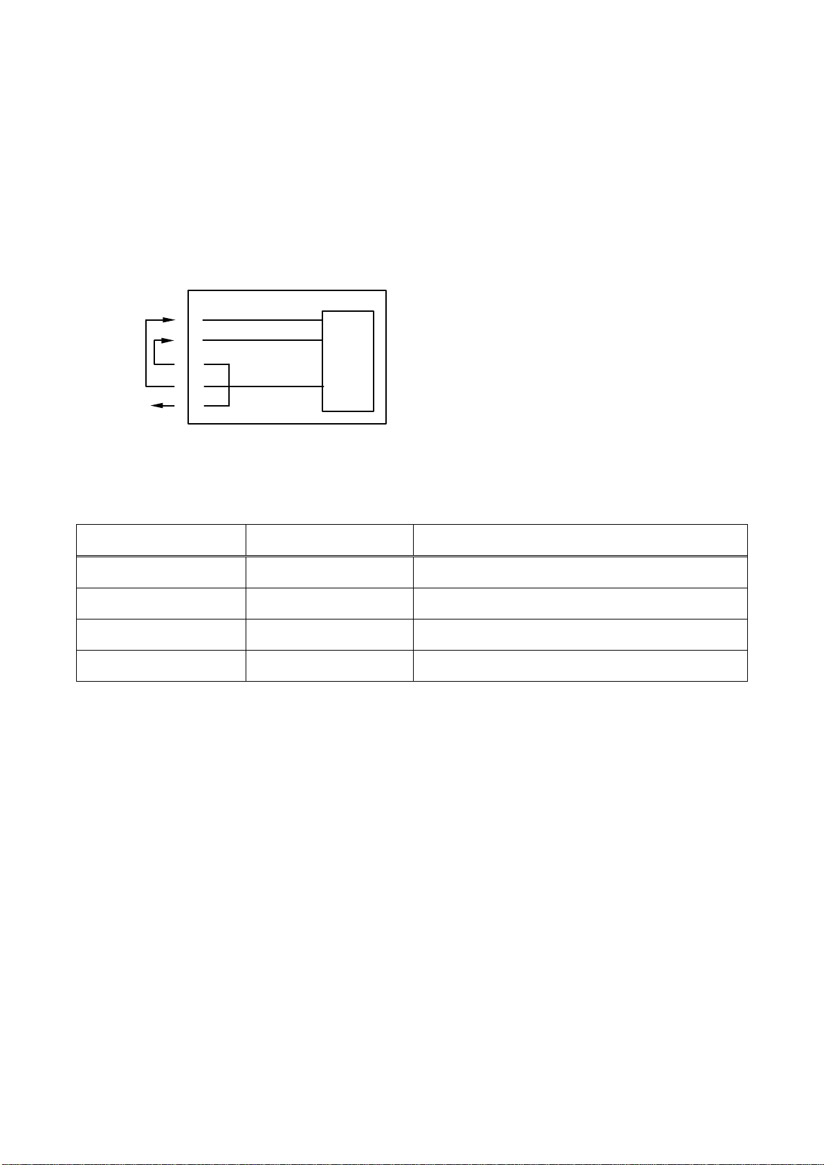
The test mode checks the ROM (Read Only Memory) and RAM (Random Access Memory) for
proper input and output of data by means of a loopback circuit. The test mode is initiated by turning
on the #4 segment of DIP switch S1.
ROM test: Checks the program area.
RAM test: Checks all memories.
SIO test: CPU loopback test. See below:
To LED
IF-2300
DATA IN1
DATA IN2
DATA OUT1
DATA OUT2
DATA OUT3
CPU
RXA0
RXA1
TXA0
LED Indicator
Error is warned with the state of LEDs, CR1 - 4.
LED No. State Condition
CR1 (Green) Blinks every second Normal
CR2 (Red) ON ROM faulty
CR3 (Red) ON RAM faulty
CR4 (Red0 ON SIO (CPU loopback) Data error
Fuse replacement
If the IF-2300 does not work, suspect the blown fuse. The fuse is accessible when the cover is
removed. It protects the electrical circuitry against overvoltage or internal short circuit. Find the
cause of problem before replacing the fuse. Only the fuse of 0.5 A should be used.
-4-
Page 9
4 INSTALLATION
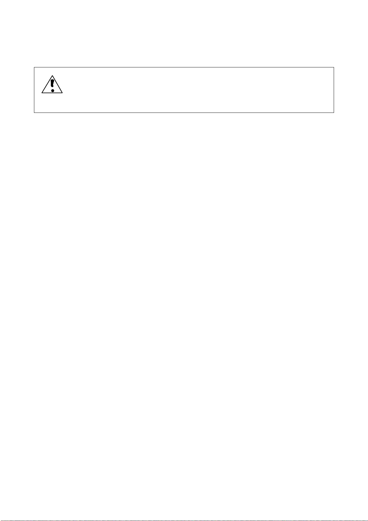
CAUTION
Turn off the power at the ship’s mains switchboard before commencing the terminal
connection of any equipment units. Only qualified personnel should work inside the
equipment.
4.1 General considerations for placement
! Maximum cable length: The IF-2300 is configured in the current loops and signal cables,
locally arranged, should be less than 5 m approx. as far as possible.
! Avoid direct sunlight.
! Select a clean and well-ventilated location.
! Select a place where shock, vibration, and noise are minimal.
! Select a location where temperature and humidity are moderate and stable.
4.2 Mounting
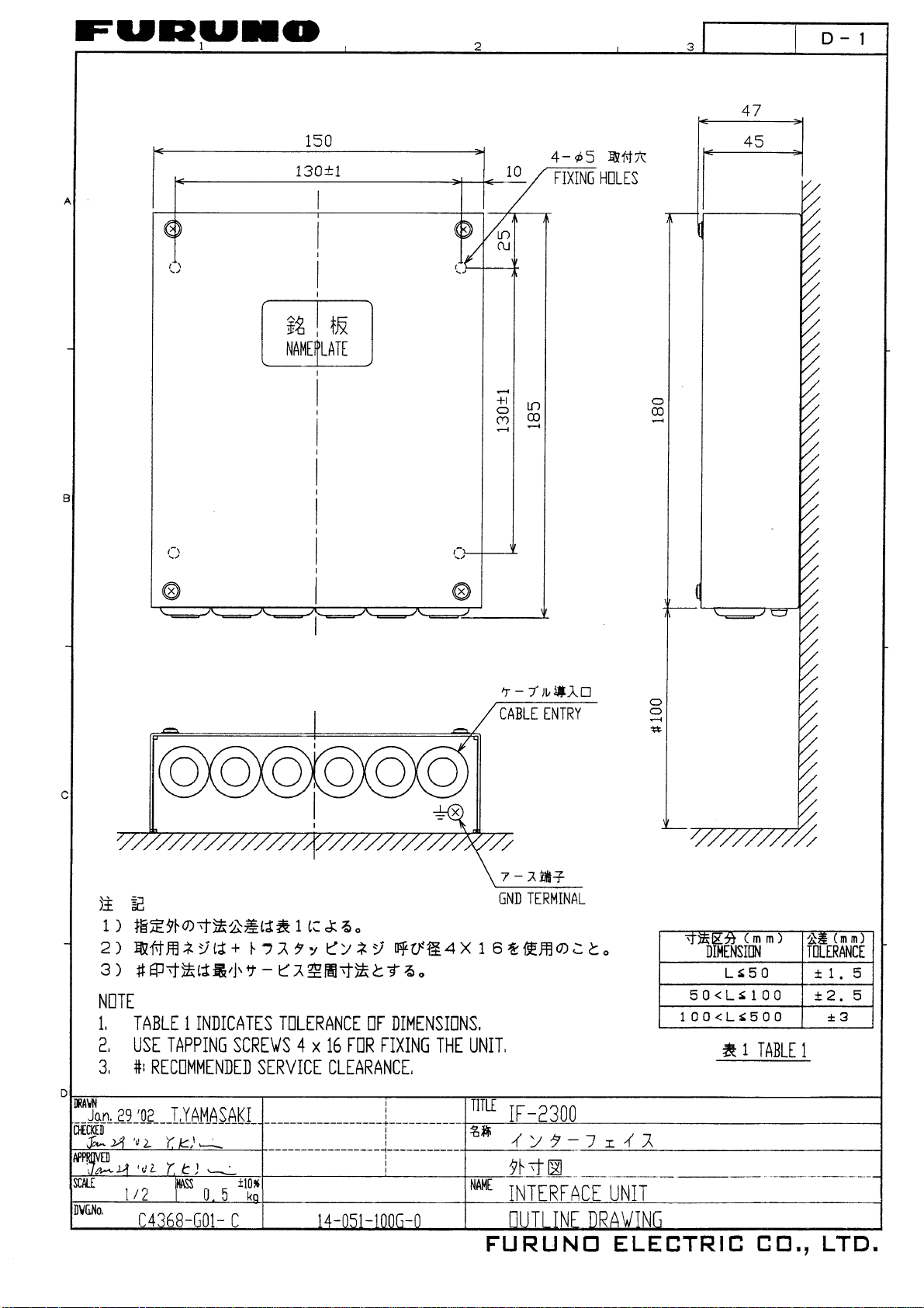
The IF-2300 may be mounted on a tabletop, bulkhead or overhead. Keep it away from the
magnetic compass by the distance stated in the specifications section.
Fixing
.1 Remove the cover.
.2 Fix the unit with tapping screws (ø4 x 16 mm, supplied). For thin walls, use nuts and bolts (to
be locally procured) instead of tapping screws.
Power cable
.1 Make a hole in the rubber bush for power cable entry (right side of the unit).
.2 Pass the power cable through the cable entrance.
.3 Remove the sheath by 30 mm.
.4 Remove the insulation on the VH connector (supplied) by 3 mm.
.5 Slip heat shrink tube over the vinyl wires of the cable. Solder the wires.
.6 Heat the heat shrink tube on each of positive and negative lines.
.7 Connect the VH connector to power jack J1 at the power inlet compartment (bottom right).
IMPORTANT: Pin 1 is for the positive (+) line, Pin 2 is for the negative (-) line.
-5-
Page 10

Signal cables
Cables are not supplied in the standard kit. Locally procure the cable TTYCS-1 (Japan
Standard Cable) or equivalent. Crimp-on lugs supplied are good for 1.25 sq cables.
.1 The interface box can accommodate maximum 2 input lines and 3 output lines. Open holes in
the rubber bushes at required ports. For each signal cable, do the same as below:
.2 Remove the outer sheath by 50 mm.
.3 Pass the signal cable through the entrance selected.
.4 Remove the inner sheath by 30 mm and the insulation of cores by 6 mm.
.5 Twist wire shield and pass it through a 25 mm tubing (local supply).
.6 Fit crimp-on lugs (supplied) to cores. Check the connection.
.7 Cover areas between the shield and the armor (if provided) with vinyl tape.
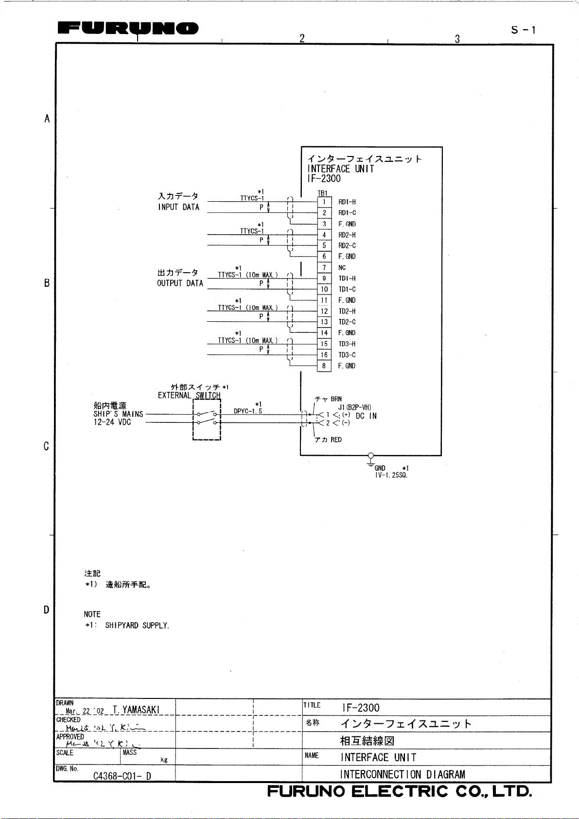
.8 Fasten wires by crimp-on lugs on the terminal strip. Refer to the interconnection diagram.
.9 Replace the cover.
.10 Fix the cable with cable clamps (local supply) outside the equipment.
TTYCS-1 (Twisted pair cable)
Current loop or RS-422
Armor
Sheath
Shield
Conductor
S = 0.75 mm
φ = 1.11 mm
Grounding
- Connect the ground wire (IV-1.25 sq) between the ground terminal and the ship’s ground bus,
to avoid interference and electrical shock.
2
-6-
Page 11
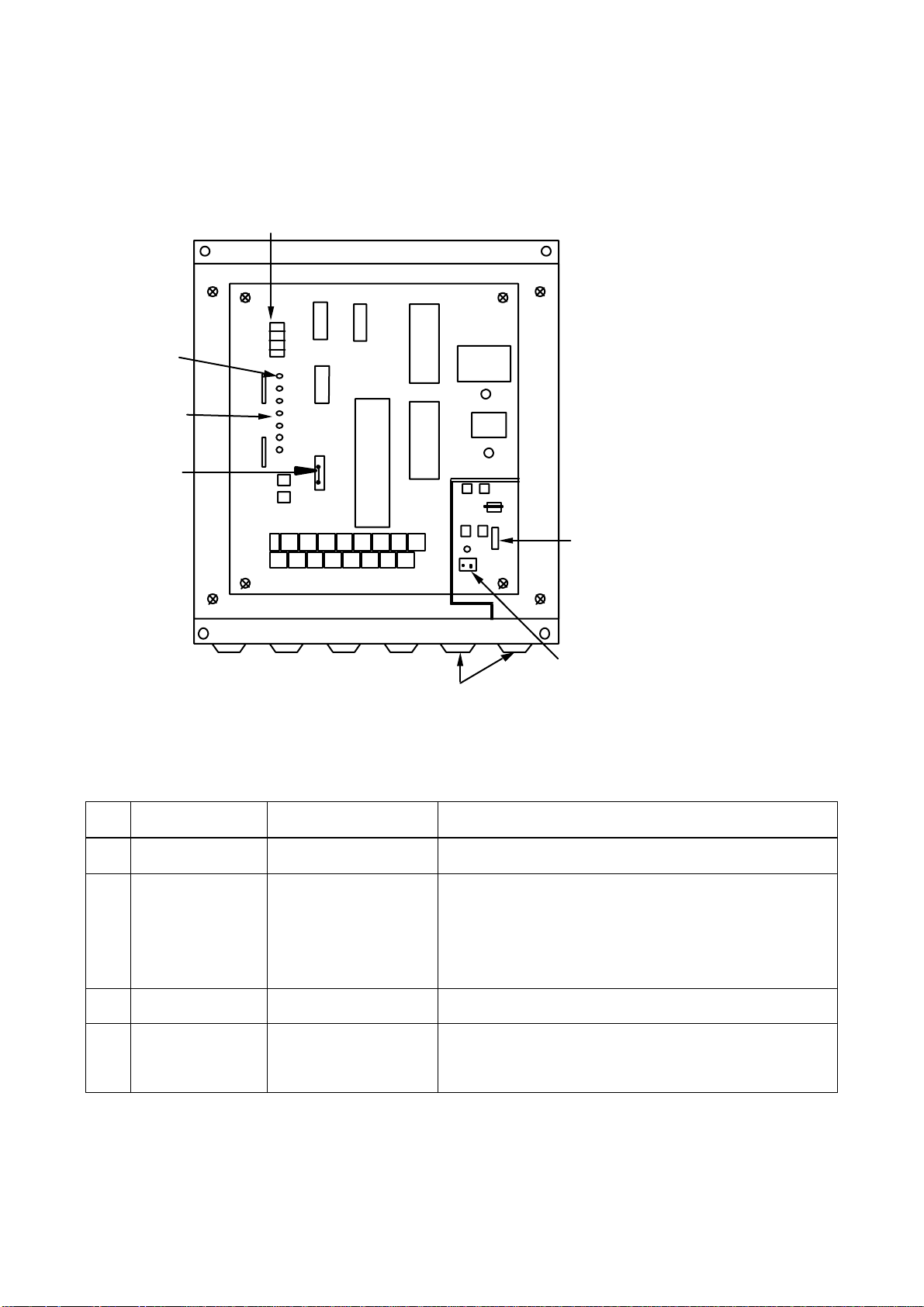
5 ADJUSTMENT
Turn off the power at the ship’s mains switch board before setting the dip switch.
DIP SWITCH S1
4
Red LEDs
Green LEDs
JP1
S1
3
2
1
CPU
TB1
RAM
ROM
Fuse
J1
Cable entrance
5.1 Setting DIP switch S1
Dual Inline Package switch S1 must be set properly.
NO. FUNCTION ON or OFF REMARKS
1 IEC 61162-1 OFF
2 NMEA OUTPUT O N: Ver 1.5
OFF: straight through
(IEC 61162-1)
3 Not used
4 Self test ON: Test
OFF: Normal
When NO. 2 is set to ON, GLL and GGA are
converted to NMEA V 1.5 and other data sentences
are output directly. When IEC 61162-1 format is
selected (NO. 1 switch: OFF), switch NO. 2 must be
set OFF.
After test is fini sh ed, tur n it to OFF for norm al
operation.
Power connector
After setting of DIP switch, turn on the power.
-7-
Page 12
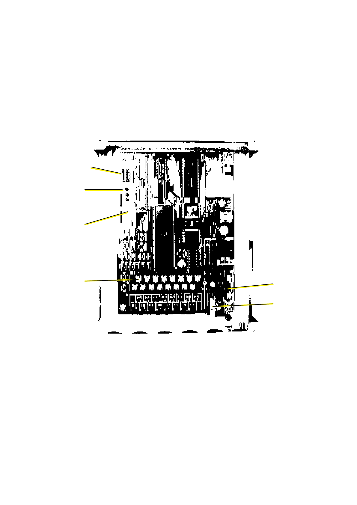
PARTS LOCATION
PARTS LIST
This equipment contains one complex module in which fault diagnosis and repair down to
component level is not practicable; therefore, parts list is omitted in this manual (IMO
A.694(17)/8.3.1). Only discrete components that may be checked or replaced by the ship
personnel are power jack and a fuse (0.5 A).
DIP SWITCH
CR4
3
2
1
CR7
TERMINAL STRIP
TB1
6
5
FUSE
POWER JACK J1
CIRCUIT BOARD 14P0272
-8-
Page 13

Page 14
Page 15
Page 16
9-52 Ashihara-cho,9-52 Ashihara-cho,
A
A
*
00080726311
**00080726311
*
*
00080726311
**00080726311
*
*
OME
43680
G
10
**OME
43680
G
10
**OME
43680
G
10
**OME
43680
G
10
*
Nishinomiya 662-8580, JAPANNishinomiya 662-8580, JAPAN
Telephone :Telephone : 0798-65-21110798-65-2111
FaxFax 0798-65-42000798-65-4200
::
The paper used in this manual
is elemental chlorine free.
FURUNO Authorized Distributor/DealerFURUNO Authorized Distributor/Dealer
ll rights reserved.
ll rights reserved.
Pub. No.Pub. No. OME-43680OME-43680
(( TENITENI ))
IF-2300IF-2300
Printed in JapanPrinted in Japan
FIRST EDITION :FIRST EDITION : FEB.FEB. 19961996
G1G1 :: AUG.AUG. 18, 200318, 2003
* 0 0 0 8 0 7 2 6 3 1 1 ** 0 0 0 8 0 7 2 6 3 1 1 *
* O M E 4 3 6 8 0 G 1 0 ** O M E 4 3 6 8 0 G 1 0 *
 Loading...