

Page 1

AIS INTERFACE
IF-1500AIS
Page 2
SAFETY INSTRUCTIONS
Safety Instructions for the Operator
WARNING
Do not disassemble or modify the
equipment.
Fire, electrical shock or serious injury can
result.
Immediately turn off the power at the
switchboard if the equipment is emitting
smoke or fire.
Continued use of the equipment can cause
fire or electrical shock. Contact a FURUNO
agent for service.
Make sure no rain or water splash leaks
into the equipment.
Fire or electrical shock can result if water
leaks in the equipment.
Safety Instructions for the Installer
WARNING
Turn off the power at the switchboard
before beginning the installation.
Fire or electrical shock can result if the
power is left on.
Do not install the equipment where it
may get wet from rain or water splash.
Water in the equipment can result in fire,
electrical shock or damage the equipment.
Be sure that the power supply is
compatible with the voltage rating of
the equipment.
Connection of an incorrect power supply
can cause fire or damage the equipment.
Keep heater away from equipment.
A heater may melt the power cord, which
can result in fire or electrical shock.
Do not place liquid-filled containers on
the top of the equipment.
Fire or electrical shock can result.
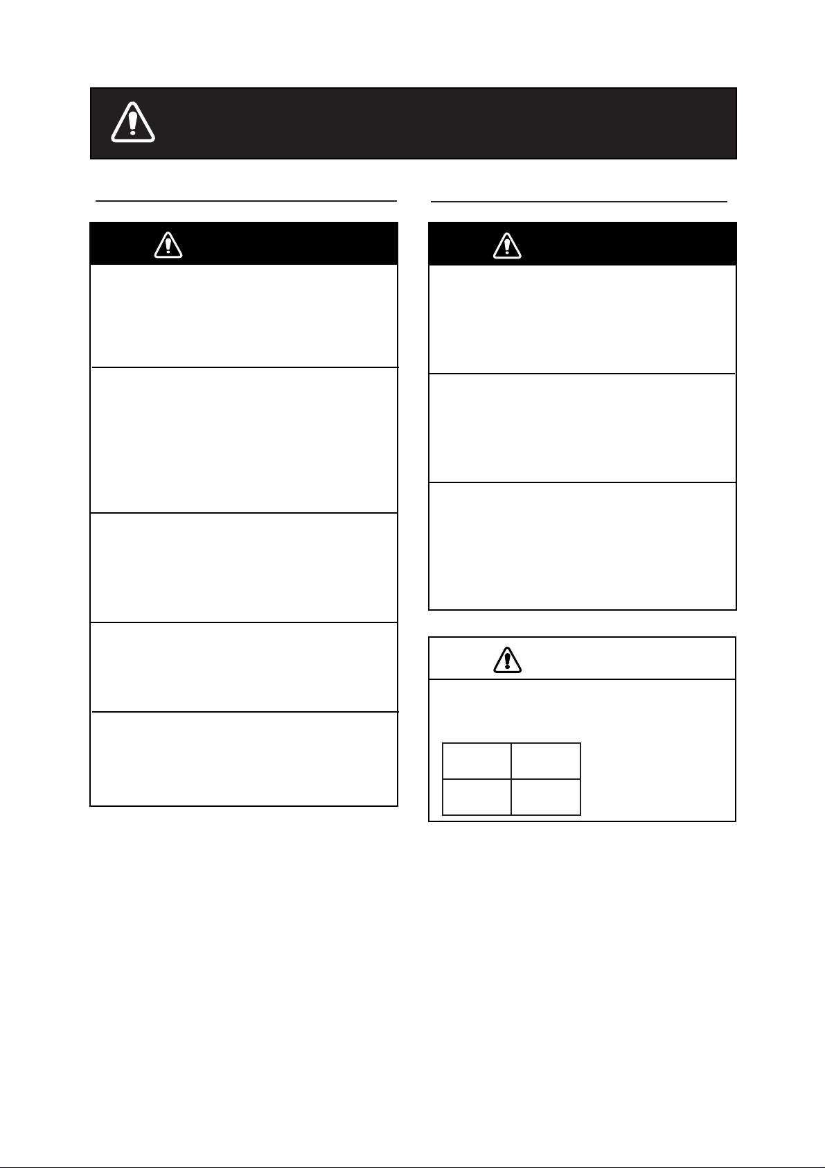
CAUTION
Observe the following compass safe
distances to prevent interference to a
magnetic compass:
Standard Steering
compass compass
0.55 m 0.35 m
1
Page 3
Foreword
FURUNO Electric Company thanks you for purchasing the IF-1500AIS AIS Interface. We
are confident you will discover why the FURUNO name has become synonymous with
quality and reliability.
Your equipment is designed and constructed to meet the rigorous demands of the marine
environment. However, no machine can perform its intended function unless properly
installed and maintained. Please carefully read and follow the installation and maintenance
procedures set forth in this manual.
Thank you for considering and purchasing FURUNO.
Features
The IF-1500AIS enables connection of the FURUNO AIS Transponder FA-100 to the
NavNet2 Series radars to display AIS information on the radar and plotter displays. AIS
target data input from the transponder are selected and sorted (by range, CPA/TCPA ,etc.),
format-converted and then output to the NavNet2 series radar.
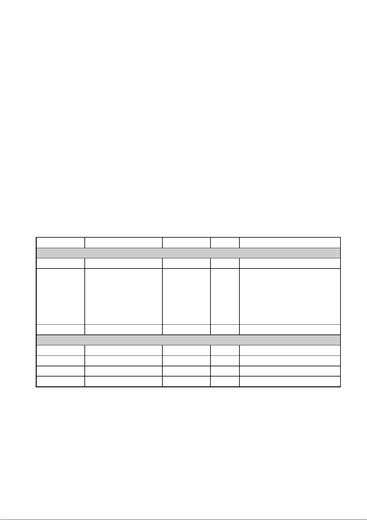
Equipment List
Name Type Code No. Qty Remarks
Sta ndard supply
AIS Interface IF-1500AIS — 1
Installation
Materials
Spare Parts SP14-03301 004-000-730 1 set
Optional supply
Cable Assy. MJ-A15A3F0013-035-3A 000-145-880 1
Cable Assy. MJ-A7SPF0003-050 000-136-730 1
Cable Assy. MJ-A6SPF0012-050 000-134-424 1
Cable Assy. MJ-A6SPF0012-100 000-133-817 1
CP14-06500 000-040-013 1 set 1) Cable assy.
MJ-A15A3F0013-035-3A
MJ-A7SPF0003-050
MJ-A6SPF0012-050
2) Self-tapping screws 4x16,
4 pcs.
2
Page 4

System Configuration
Cable
MJ-A6SPF0012-050 (5 m)*
* 10 m cable optionally
available
NavNet2 Series
Radar, Plotter
AIS Transponder
FA-100
Cable
MJ-A7SPF0003-050 (5 m)
IF-1500AIS
Cable
MJ-A15A3F0013-035
12-24 VDC
Mounting
The unit can be mounted on a desktop or a bulkhead. When choosing a mounting location,
keep in mind the following points:
• Consider cable lengths.
• Choose a location away from rain and water splash and one which is not in direct
sunlight.
• Observe the maintenance space noted in the outline drawing to facilitate servicing.
• Observe the compass safe distances noted in the safety instructions at the beginning of
this manual.
Fix the unit to the mounting location with four self-tapping screws (4x16). Connect cables
referring to the interconnection diagram. Run a ground wire (local supply) between the
ground terminal and ship’s superstructure.
3
Page 5

Wiring
A
A
A
plug
A
Refer to the interconnection diagram at the back of this manual and the illustration below.
For IEC 61162-2
IS
-
External display
-
Aux. display
-
Pilot
Notice:
RD
RD B
TD
TD B
ISO GND
ISO GND
F.G.
WHT
BLK
YEL
GRN
RED
BLU
MJ-A7SPF0003-050
Do not connect "SIG. GND" of the IF-1500AIS
to "Frame Ground".
For IEC 61162-1, NMEA-0183
IF-1500AIS
J1:AIS IN
1
TD A
2
TD B
3
RD H
4
RD C
5
SIG. GND
6
SIG. GND
7
F.G.
IS
-
External display
-
Aux. display
-
Pilot plug
RD H
RD C
TD A
TD B
N.C
N.C
F.G.
Notice:
WHT
BLK
YEL
GRN
RED
BLU
MJ-A7SPF0003-050
IF-1500AIS
J1:AIS IN
TD A
1
TD B
2
RD H
3
RD C
4
SIG. GND
5
SIG. GND
6
F.G.
7
Do not connect "SIG. GND" of the IF-1500AIS
to "Frame Ground".
4
Page 6

Data Sentences
The following data sentences are input to and output from the AIS Interface.
AIS
Transponder
ABM
BBM
ACK
LRI/LRF
AIS
Interface
ACK
TGT Qty
Sort Condition
VDM
VDO
ALR
ABK
TXT
ACA
LRI/LRF
VDM
VDO
ALR
TXT
P Sentences
NavNet2 Series
Radar, Plotter
Operation
No operation is required of the user. All AIS-related operations are carried out from the
NavNet2 series radar or plotter.
Cleaning
Dust may be removed from the cabinet with a soft dry cloth. For stubborn dirt, water-diluted
mild detergent may be used. Do not use chemical-based cleaning agents to clean the
cabinet; they can remove paint and markings.
Replacement of Fuse
The 3A fuse in the power cable protects the
equipment from reverse polarity and equipment
trouble. If the fuse blows, find the cause before
replacing the fuse. If it blows after replacement
request service.
Use the proper fuse.
Use of a wrong fuse can result in damage
to the equipment or cause fire.
WARNING
5
Page 7

FURUNO
SPECIFICATIONS OF
AIS INTERFACE
IF-1500AIS
1. PORTS
1.1 Number of ports 2 ports (IN/OUT)
1.2 Baud rate 38,400 bps
1.3 AIS IN port (RS-485) Input data: VDM, VDO, ALR, ABK, TXT, ACA, LRI/LRF
Output data: ABM, BBM, ACK, LRI/LRF
1.4 DATA OUT port Input data: ACK, Target quantity, Sort condition
Output data: VDM, VDO, ALR, TXT, P-sentences
IF-1500AIS
1.5 Digital interface IEC 61162-
2
2. ENVIRONMENTAL CONDITIONS
2.1 Useable temperature -15°C to 55°C
2.2 Relative humidity 95%(40°C)
2.3 EMC IEC 60945
2.4 Waterproofing IP20
3. POWER SUPPLY
12-24 VDC, 0.2-0.1 A
4. COLOR
N3.0
SP - 1 E4435S01B
Page 8

PACKING LIST
A-1
IF‑1500AIS
14CS‑X‑9851 ‑3
1/1
NAME
OUTLINE
DESCRIPTION/CODE№
ユニット UNIT
AISインターフェイス
AISINTERFACE
IF‑1500AIS
000‑152‑849
予備品 SPAREPARTS SP14‑03301
ヒューズ
FUSE
FGBO‑A3AAC125V
000‑549‑063
工事材料 INSTALLATIONMATERIALS CP14‑06500
ケーブル組品MJ
POWERCABLE
ケーブル組品MJ
CABLEASSY.
ケーブル組品MJ
SIGNALCABLEASSEMBLY
MJ‑A15A3F0013‑035‑3A
000‑145‑880
MJ‑A7SPF0003‑050
000‑136‑730
MJ‑A6SPF0012‑050
000‑134‑424
Q'TY
1
2
1
1
1
+トラスタッピンネジ
SELF‑TAPPINGSCREW
図書 DOCUMENT
取扱説明書
OPERATOR'SMANUAL
4X16SUS3041シュ
4
000‑802‑080
OMC‑44350‑*
1
000‑152‑852
(略図の寸法は、参考値です。DIMENSIONSINDRAWINGFORREFERENCEONLY.)
14CS‑X‑9851
Page 9

Y.Hatai
Page 10

NC
Y.Hatai
TD1‑A
TD1‑B
RD1‑H
*1
*1
DATA2
MJ‑A6SPF
5/10m,φ6(MAX.10m)
MJ‑A6SPF
DATA OUT
RD1‑C
34125
キ
ミドリシロアオ
YEL
GRN
12345
TD2‑A
TD2‑B
MODEL 18X4C,19X4C SERIES
NavNet2 船舶用レーダー/プロッタ
NavNet2 MARINE RADAR/PLOTTER
MJ‑A6SPF0012‑050/100,
3421
WHT
RD2‑H
BLU
RD2‑C
SHIELD
6
6
NC
F.G.
NavNet2 船舶用レーダー/プロッタ
NavNet2 MARINE RADAR/PLOTTER
TD1‑A
MODEL 17X4C SERIES, FR‑8002 SERIES
MJ‑A7SPF0007
TD1‑B
DATA1
123
*1
MJ‑A7SPF
シロアオキ
‑050(5m)
WHT
YEL
BLU
RD1‑H
RD1‑C
4
ミドリ
GRN
+12V
5
SOLDER
GND
6
SHIELD
7
GND
IF‑1500AIS
AISインターフェイス
TYPE
名称
IV‑2SQ. *2
D. MILLS
TAKAHASHI.T
相互結線図
NAME
AIS INTERFACE UNIT
kg
INTERCONNECTION DIAGRAM
C4435‑C01‑ B
MAY 20,'05
DRAWN
CHECKED
APPROVED
DWG.No.
SCALE MASS
IF‑1500AIS
AIS INTERFACE UNIT
AIS インターフェイスユニット
*1
AIS IN
TD1‑A
TD1‑B
RD1‑H
23456
1
SIG. GND
RD1‑C
SIG. GND
7 F.G.
F.G.
DC IN ‑
DC IN +
PWR 12‑24VDC
123
*1
FA‑100 接続箱 CB‑100
Junction Box
Terminal for External Display/
Aux. Display/Pilot Plug.
外部表示器/パイロットプラグなどの端子台
MJ‑A7SPF
MJ‑A7SPF003‑050, 5m,φ6
シロクロキ
WHT
BLK
RD‑A
IEC‑61162‑2の場合
YEL
RD‑B
For IEC‑61162‑2
ミドリ
GRN
TD‑A
RED アカ
TD‑B
MJ‑A3SPF
シロ
クロ
WHT
BLK
シロクロキ
ミドリ
MJ‑A15A3F0013‑035‑3A
BLU アオ
GNDISO
GNDISO
F.G.
WHT
BLK
RD‑H
YEL
RD‑C
GRN
TD‑A
RED アカ
TD‑B
BLU アオ
NC
NC
F.G.
FUSE 3A
3.5m,φ6
12‑24VDC
IF‑1500 AISのSIG.GNDはFG(フレームグランド)に接続しないこと。
IEC‑61162‑1/NMEA‑0183の場合
For IEC‑61162‑1/NMEA‑0183
DO NOT CONNECT "SIG. GND" of IF‑1500AIS to "FG" (Frame Ground).
注記
*1) コネクタは工場にて取付済み。
*2) 造船所手配。
NOTE
*1. CONNECTOR PLUG FITTED AT FACTORY.
*2. SHIPYARD SUPPLY.
A
B
C
Page 11

Page 12

この図書には環境配慮型漂白
。
〒
662‑8580
兵庫県西宮市芦原町
9番52
号
2005
年4月
初版発行
PUB.No.
OMC‑44350‑A2
*
0
*
0
*
0
*
0
(
DAMI
)
IF‑1500AIS
*
O
*
O
*
O
*
O
方式の用紙を使用しています
・機器の修理・使用方法等に関するお問い合わせは、お買い上げの販売店・代理店、あるいは
最寄りの当社各支店・営業所へお願いします。
発行
本書の無断複写複製(コピー)は特定の
場合を除き、当社の権利侵害になります。
PrintedinJapan
・お問い合わせは
2005年 5月 23日 A2 版発行
0015285200*
0015285200*
0015285200*
0015285200*
*00015285200*
MC44350A20*
MC44350A20*
MC44350A20*
MC44350A20*
*OMC44350A20*
 Loading...