

Page 1
COLOR GPS/PLOTTER
Back
GP-3500
Page 2

9-52 Ashihara-cho,9-52 Ashihara-cho,
A
A
*
00014677602
**00014677602
*
*
00014677602
**00014677602
*
*
OME
44210
F
40
**OME
44210
F
40
**OME
44210
F
40
**OME
44210
F
40
*
Nishinomiya 662-8580, JAPANNishinomiya 662-8580, JAPAN
Telephone :Telephone : 0798-65-21110798-65-2111
FaxFax 0798-65-42000798-65-4200
ll rights reserved.
ll rights reserved.
::
Printed in JapanPrinted in Japan
Pub. No.Pub. No. OME-44210OME-44210
Your Local Agent/Dealer Your Local Agent/Dealer
IRST EDITION :
IRST EDITION : JULJUL.. 20032003
F4F4 :: APRAPR.. 13, 200513, 2005
Thepaperusedinthismanual
iselementalchlorinefree.
(( TATATATA ))
GP-3500GP-3500
* 0 0 0 1 4 6 7 7 6 0 2 ** 0 0 0 1 4 6 7 7 6 0 2 *
* O M E 4 4 2 1 0 F 4 0 ** O M E 4 4 2 1 0 F 4 0 *
Page 3
SAFETY INSTRUCTIONS
WARNING
ELECTRICAL SHOCK HAZARD
Do not open the equipment.
Only qualified personnel
should work inside the
equipment.
Do not disassemble or modify the
equipment.
Fire, electrical shock or serious injury can
result.
Immediately turn off the power at the
switchboard if the equipment is emitting
smoke or fire.
Continued use of the equipment can cause
fire or electrical shock. Contact a FURUNO
agent for service.
Keep heater away from equipment.
A heater can melt the equipment's power
cord, which can cause fire or electrical
shock.
Do not operate the unit with wet hands.
CAUTION
No one navigation device should ever be
solely replied upon for the navigation of
a vessel.
Always confirm position against all available
aids to navigation, for safety of vessel and
crew.
Use the proper fuse.
Fuse rating is shown on the power cable.
Use of a wrong fuse can result in damage
to the equipment.
No single navigation aid should even be
relied upon as the exclusive means for
navigating your vessel.
The navigator is responsible for checking
all aids (including nautical charts) available
to confirm his position. Electronic aids are
intended to assist, not replace, the
navigator.
Do not use the equipment for other than
its intended purpose.
Erectlic shock can result.
WARNING LABEL
About the TFT LCD
The TFT LCD is constructed using the
latest LCD techniques, and displays
99.99% of its pixels. The remaining 0.01%
of the pixels may drop out or blink,
however this is not an indication of
malfunction.
A warning label is attached to the equipment. Do not remove the label. If the
label is missing or damaged, contact
a FURUNO agent or dealer about
replacement.
To avoid electrical shock, do not
remove cover. No user-serviceable
parts inside.
WARNING
Name: Warning Label (1)
Type: 86-003-1011-1
Code No.: 100-236-231
i
Page 4

FOREWORD
Congratulation on your choice of t he FURUNO GPS COLOR PLOTTER
GP-3500. For over 50 years FURUNO Electric Company has enjoyed an
enviable reputation for innovative and dependable marine electronics equipment.
This dedication to excellence is furt hered by our extensive global network of
agents and dealers.
The equipment is designed and constructed to meet the rigorous demands of
the marine environment. Ho wever, no machine can perform its intended function
unless installed, operated and m aintained properly. Please carefully read and
follow the recommended procedures for operation and maintenance.
Feature
The GP-3500 consists of the display unit and antenna unit. The display unit is
totally integrated GPS receiver and color video plott er.
The GPS receiver tracks up to thirteen satellites (GPS: 12, WAAS: 1)
simultaneously, and an 8-state Kalman filter ensures optimum accuracy in
determination of vessel position, course and speed.
Main features of the GP-3500
• Bright 10.4-inch color TFT LCD with
temperature compensated tone and
brilliance control
• Simplified operation using individual keys,
ENTER knob and trackball
• Three lines, main and sub of own ship’s
track, and other ship’s track can be
displayed simultaneously.
• Accepts FURUNO and NavCharts
(NAVIONICS) charts, or C-MAP NT charts
(C-MAP), depending on specification. All
names mentioned are registered
trademarks of their respective companies.
• Fast chart redraw.
• Built-in backup memory stores 80,000
points total of own ship’s tracks and marks
• Stores 3500 waypoints and 200 routes with
up to 35 waypoints.
• Man overboard feature records latitude and
longitude coordinates at time of man
overboard.
• Alarms: Arrival, Anchor Watch, Cross-track
Error, Proximity, Speed, Trip, Temperature,
Current and Depth.
• User programmable PROG key
• Own ship and cursor positions may be
shown in latitude and longitude, Loran A,
Loran C or Decca LOPs.
• Data storage on memory cards.
• Improved position accuracy with optional
DGPS beacon receiver.
ii
Page 5

TABLE OF CONTENTS
SYSTEM CONFIGURATIONS ............................................................................vii
1. BASIC OPERATION ......................................................................................1-1
1.1 Controls Description ..................................................................................................1-1
1.1.1 Display unit .....................................................................................................1-1
1.1.2 Remote controller............................................................................................1-2
1.2 Loading a Mini Chart Card.........................................................................................1-3
1.3 Turning the Power On/Off..........................................................................................1-4
1.4 Adjusting Brilliance and Hue......................................................................................1-6
1.4.1 Adjusting display brilliance ..............................................................................1-6
1.4.2 Adjusting control panel dimmer .......................................................................1-7
1.4.3 Selecting hue..................................................................................................1-9
1.5 Selecting a Display..................................................................................................1-10
1.6 MOB Mark............................................................................................................... 1-11
1.7 Using PROG Key.....................................................................................................1-12
1.8 Simulation Mode......................................................................................................1-13
1.9 Menu Overview........................................................................................................1-15
2. PLOTTER AND PILOT DISPLAY DESCRIPTION.........................................2-1
2.1 Plotter and Pilot Displays...........................................................................................2-1
2.1.1 Plotter display..................................................................................................2-1
2.1.2 Pilot display.....................................................................................................2-2
2.1.3 NAV INFO 1 display........................................................................................2-3
2.1.4 Compass plotter (or pilot) display....................................................................2-4
2.1.5 GPS status display..........................................................................................2-6
2.2 Operating the Cursor.................................................................................................2-7
2.3 Shifting the Display....................................................................................................2-8
2.4 Changing Chart Scale................................................................................................2-8
2.5 Measuring Range and Bearing Between two Points..................................................2-9
2.6 Using the VRM (Variable Range Marker)................................................................. 2-11
2.7 Mini Chart Cards......................................................................................................2-12
3. TRACK...........................................................................................................3-1
3.1 Displaying Track........................................................................................................3-1
3.1.1 Own ship’s track..............................................................................................3-1
3.1.2 Sub track.........................................................................................................3-3
3.1.3 Other ship’s track............................................................................................3-4
3.2 Stopping, Restarting Plotting of Own Ship Track........................................................3-5
3.2.1 Displaying own ship’s track while track plotting is stopped ..............................3-6
3.2.2 Connecting own ship’s track when resuming plotting.......................................3-7
3.3 Changing Track Color................................................................................................3-8
3.3.1 Changing own ship’s track color......................................................................3-8
3.3.2 Changing sub track color.................................................................................3-8
3.3.3 Changing target track color.............................................................................3-8
iii
Page 6

v
3.3.3 Changing target track color............................................................................. 3-8
3.3.4 Aut omati cally changin g ow n shi p’ s track c olor by water tem p er at ur e.............. 3-9
3.3.5 Changing own ship’s track color according to depth....................................... 3-11
3.4 Changing Track Line Type....................................................................................... 3-13
3.5 Track Plotting Method, Interval................................................................................ 3-13
3.5.1 Track plotting method.................................................................................... 3-13
3.5.2 Track plotting interval.................................................................................... 3-14
3.6 Erasing Tracks ........................................................................................................ 3-15
3.6.1 Erasing tracks by color.................................................................................. 3-15
3.6.2 Erasing tracks by line type............................................................................ 3-18
3.7 Editing Tracks.......................................................................................................... 3-19
3.8 Changing Track Memory Capacity........................................................................... 3-20
4. MARKS & LINES ...........................................................................................4-1
4.1 Entering Marks.......................................................................................................... 4-1
4.2 Changing Mark Color ................................................................................................ 4-3
4.3 Changing Mark Size.................................................................................................. 4-4
4.4 Entering Lines........................................................................................................... 4-5
4.5 Selecting Line Ty p e................................................................................................... 4-5
4.6 Erasing Marks, Lines................................................................................................. 4-6
4.7 Editing Marks, Lines.................................................................................................. 4-9
4.8 Displaying Mark Data.............................................................................................. 4-10
4.9 Target Mark (TLL).................................................................................................... 4-10
5. WAYPOINT.....................................................................................................5-1
5.1 Entering Waypoints................................................................................................... 5-1
5.1.1 Entering waypoints at own ship’s position....................................................... 5-1
5.1.2 Entering waypoints by the cursor.................................................................... 5-2
5.1.3 Entering waypoints by latitud e an d lo ngi t ud e posi tion..................................... 5-3
5.1.4 Entering waypoints by range and bearing....................................................... 5-6
5.1.5 Entering waypoints by Loran A or Lor a n C LOPs............................................. 5-7
5.1.6 Entering waypoints by Decca LOPs................................................................ 5-8
5.2 Editing Waypoint Data............................................................................................... 5-9
5.3 Erasing Individual W a yp oints................................................................................... 5-10
5.4 Searching Waypoints................................................................................................5-11
5.5 Setting Ship’s Sp ee d for TTG.................................................................................. 5-12
5.6 Displaying Waypoint Data........................................................................................ 5-13
TM
5.7 Changing Waypoint Mark Size (NAVchart
/FURUNO only)................................... 5-14
6. ROUTE ..........................................................................................................6-1
6.1 Entering Routes........................................................................................................ 6-1
6.1.1 Entering routes using exis tin g w aypoints ........................................................ 6-1
6.1.2 Creating track-based routes............................................................................ 6-4
6.2 Editing Routes........................................................................................................... 6-5
6.2.1 Inserting waypoints......................................................................................... 6-5
6.2.2 Removing waypoints fr om routes.................................................................... 6-5
6.3 Erasing Routes.......................................................................................................... 6-6
6.4 Setting Ship’s Sp ee d for TTG.................................................................................... 6-6
i
Page 7

7. NAVIGATION..................................................................................................7-1
7.1 Navigating to Quick Points.........................................................................................7-1
7.2 Navigating to a Waypoint...........................................................................................7-7
7.3 Following a Route....................................................................................................7-10
7.4 Canceling Navigation...............................................................................................7-12
8. ALARMS ........................................................................................................8-1
8.1 Audio Alarm On/Off....................................................................................................8-2
8.2 Arrival A larm/Ancho r Watch Al arm.............................................................................8-3
8.3 XTE (Cross Track Error) Alarm/Border Alarm.............................................................8-4
8.4 Proximity Alarm..........................................................................................................8-5
8.5 Speed Alarm..............................................................................................................8-6
8.6 Trip Log Alarm...........................................................................................................8-6
8.7 Temperature Alarm ....................................................................................................8-7
8.8 Shear Alarm...............................................................................................................8-7
8.9 Bottom Alarm.............................................................................................................8-8
9. CUSTOMIZING YOUR UNIT..........................................................................9-1
9.1 CHART SETUP Menu................................................................................................9-1
9.1.1 Offsetting the chart..........................................................................................9-1
9.1.2 CHART SETUP menu items description..........................................................9-4
9.1.3 CONTOUR LINES SETUP menu....................................................................9-7
9.2 PLOTTER SETUP Menu...........................................................................................9-8
9.2.1 Setting TD display...........................................................................................9-8
9.2.2 Resetting trip distance...................................................................................9-10
9.2.3 Selecting range of PLOTTER (PILOT) display...............................................9-10
9.3 DISPLAY SETUP Menu...........................................................................................9-12
9.4 NAVIGATOR SETUP Menu ..................................................................................... 9-17
9.5 PROGRAMMABLE KEYS & REMOTE CONTROLLER SETUP Menu.....................9-22
9.5.1 Programmable key setup...............................................................................9-22
9.5.2 Remote controller (option) setup...................................................................9-25
9.6 DISPLAY MODES & NAV DATA WINDOW SETUP Menu........................................9-27
9.6.1 Setting the DISPLAY MODE screen..............................................................9-27
9.6.2 Setting the navigation data window...............................................................9-30
9.7 I/O PORT SETUP Menu..........................................................................................9-34
9.8 TEST & MEMORY CLEAR Menu.............................................................................9-37
9.8.1 Setting the password.....................................................................................9-37
9.8.2 Removing the password................................................................................9-38
10. RECORDING & PLAYING BACK DATA ...................................................10-1
10.1 Recording Data........................................................................................................ 10-1
10.2 Memory Card Operation..........................................................................................10-2
10.2.1 Formatting the memory card .........................................................................10-2
10.2.2 Saving data to a memory card.......................................................................10-4
10.2.3 Displaying data from a memory card.............................................................10-6
10.2.4 Playing back data from a memory card .........................................................10-7
10.2.5 Del eting files..................................................................................................10-8
v
Page 8

10.3 Automatic Backup Function......................................................................................10-9
10.3.1 Backup to a memory card..............................................................................10-9
10.3.2 Backup to internal memory ..........................................................................10-10
10.4 Internal Memory..................................................................................................... 10-11
10.4.1 Saving data to internal memory....................................................................10-11
10.4.2 Displaying tracks and marks stored in the internal memory..........................10-12
10.4.3 Playing back data from the internal memory................................................10-14
10.5 Uploading, Downloading Data ................................................................................10-15
10.5.1 Downloadi ng data........................................................................................10-15
10.5.2 Uploading data.............................................................................................10-17
11. MAINTENANCE & TROUBLESHOOTING................................................ 11-1
11.1 Maintenance.............................................................................................................11-1
11.2 Replacement of Fuse ...............................................................................................11-2
11.3 Replacement of Battery............................................................................................ 11-2
11.4 Trackball Maintenance ............................................................................................. 11-3
11.5 Simple Troubleshooting............................................................................................11-4
11.6 Diagnostics .............................................................................................................. 11-5
11.6.1 Memory I/O test.............................................................................................11-5
1 1.6.2 Ke yboard test.................................................................................................11-7
1 1 .6.3 Test pattern....................................................................................................11-8
11.7 Clearing the Working Memory ..................................................................................11-9
11.8 Cold Start ............................................................................................................... 11-10
MENU TREE....................................................................................................AP-1
WORLD TIME CHART....................................................................................AP-6
GEODETIC CHART LIST ...............................................................................AP-7
ICONS .............................................................................................................AP-8
WHAT IS WAAS?............................................................................................AP-9
SPECIFICATIONS........................................................................................... SP-1
DECLARAT ION OF CONFORM ITY
vi
Page 9
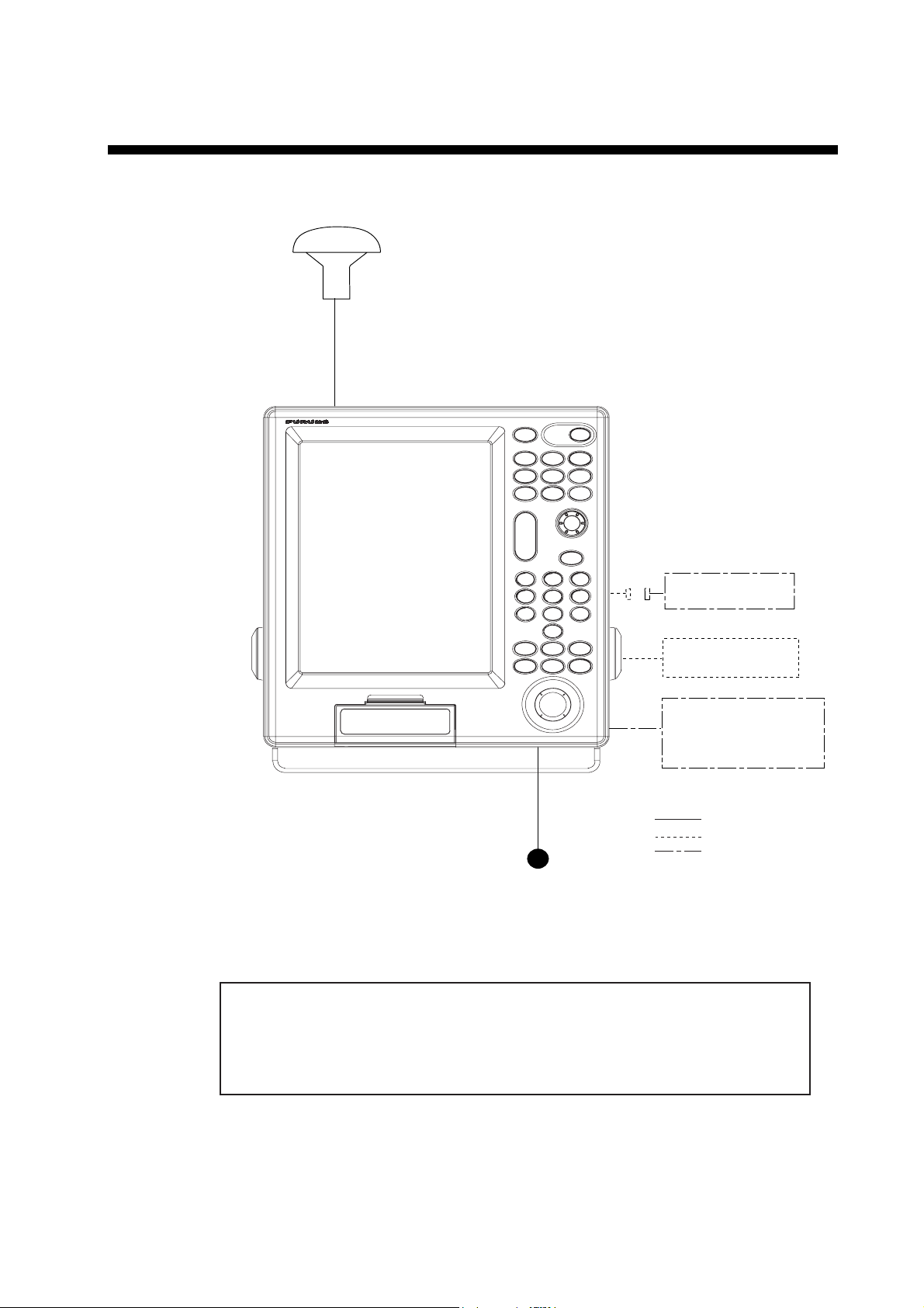
SYSTEM CONFIGURATIONS
Display unit
GP-3500
GPA-017S/GPA-019S*
(option)
External monitor
Remote controller
External equipment
(Autopilot, radar, etc.)
: Standard supply
: Option
: User supply
12-24 VDC
*: Only when the optional beacon
receiver kit is installed.
This GPS receiver complies with Canadian standard RSS-210 (Low Power
License-Exempt Radio communication Devices).
Operation is subject to the following two conditions:
(1) this device may not cause interference, and
(2) this device must accept any interference, including interference that may
cause undesired operation of the device.
vii
Page 10

This page is intentionally left blank.
viii
Page 11
1. BASIC OPERATION
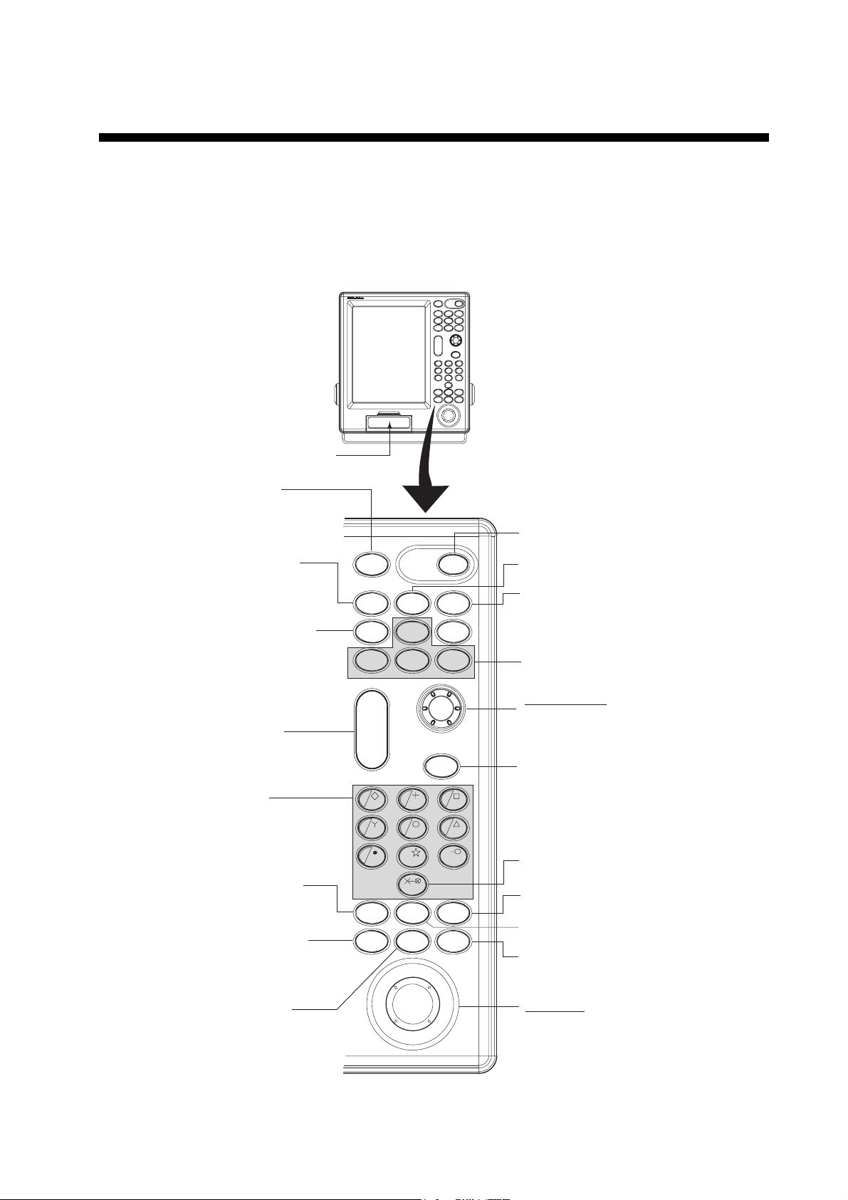
1.1 Controls Description
1.1.1 Display unit
When you correctly execute an operation, the unit generates a beep. Invalid
operation causes the unit to emit three beeps.
Card slot
Opens the BRILLIANCE
window.
Momentary press: Registers
Long press:
(more than
3 seconds)
Displays the DISPLAY MODE
screen.
own ship's
positions.
Marks man
overboard
position.
BRILL
SAVE
MOB
DISP
PROG2
WPT
PROG1
PROG3
POWER
GOTO
MENU
PROG4
Turns power on/off.
Opens the SAVE WPT window.
Sets/releases the destination.
Executes program assigned.
Enlarges/shrinks display.
• Enters numeric data.
• Enters mark.
• Selects menu item.
Opens the CHANGE MARK
COLOR window.
• Displays/erases the cursor.
• Switches + to - and vice vevsa.
• Switches N to S, E to W and
vice vevsa.
Moves own ship's position
or cursor position to center.
ZOOM
IN
ZOOM
OUT
1
4
789
MARK
COLOR
CURSOR
ON/OFF
5
T
0
VRM
CENTER
CLEAR
D
TRACK
COLOR
PLOT
INTVL
Control panel
ENTER knob
Push: Registers numeric data
or operation.
Rotate: Selects menu items.
• Silences the alarm.
• Erases marks and waypoints.
32
6
• Clears alpnanumeric data.
Mesures the bearing and range
between two points.
Opens the CHANGE SHIP'S
TRACK COLOR window.
Shows the VRM.
Changes the track plotting method
and plotting interval.
Trackball
• Moves the cursor.
• Selects the menu item.
1-1
Page 12
1. BASIC OPERATION
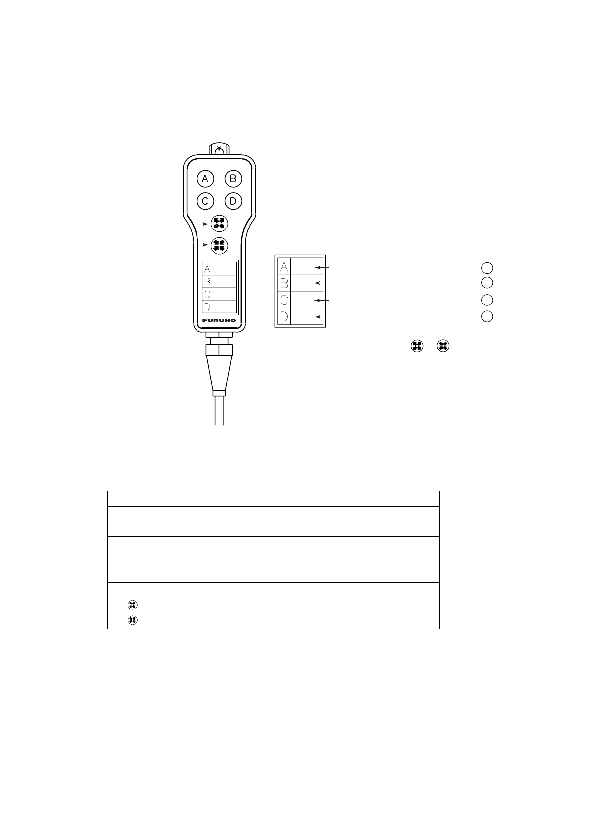
1.1.2 Remote controller
The remote controller provides for armchair control of the display unit. It has six
keys, all of which may be programmed by the user.
Hole for hooking.
ZOOM IN
ZOOM OUT
Label
Record the function registered to key.
Record the function registered to key.
Record the function registered to key.
Record the function registered to key.
Note: When proqramming the or key,
make a mental note of their programs,
as there is no space on the remote
confroller for recordings its program.
A
B
C
D
Remote controller
The default key functions are as below.
Key Function
A
B
Enter a waypoint with the next consecutive waypoint
number at the own ship (or cursor) position.
Same as pressing the [ENTER] knob on the control
panel.
C Same as [CLEAR] key function.
D Same as [1] key function.
Same as [ZOOM IN] key function.
Same as [ZOOM OUT] key function.
For how to program the remote controller, see paragraph 9.5.2.You can program
other function to each key (See paragraph 9.5.2.) Record the function name on
the label on the remote controller, using an oil-based felt-tip pen.
1-2
Page 13
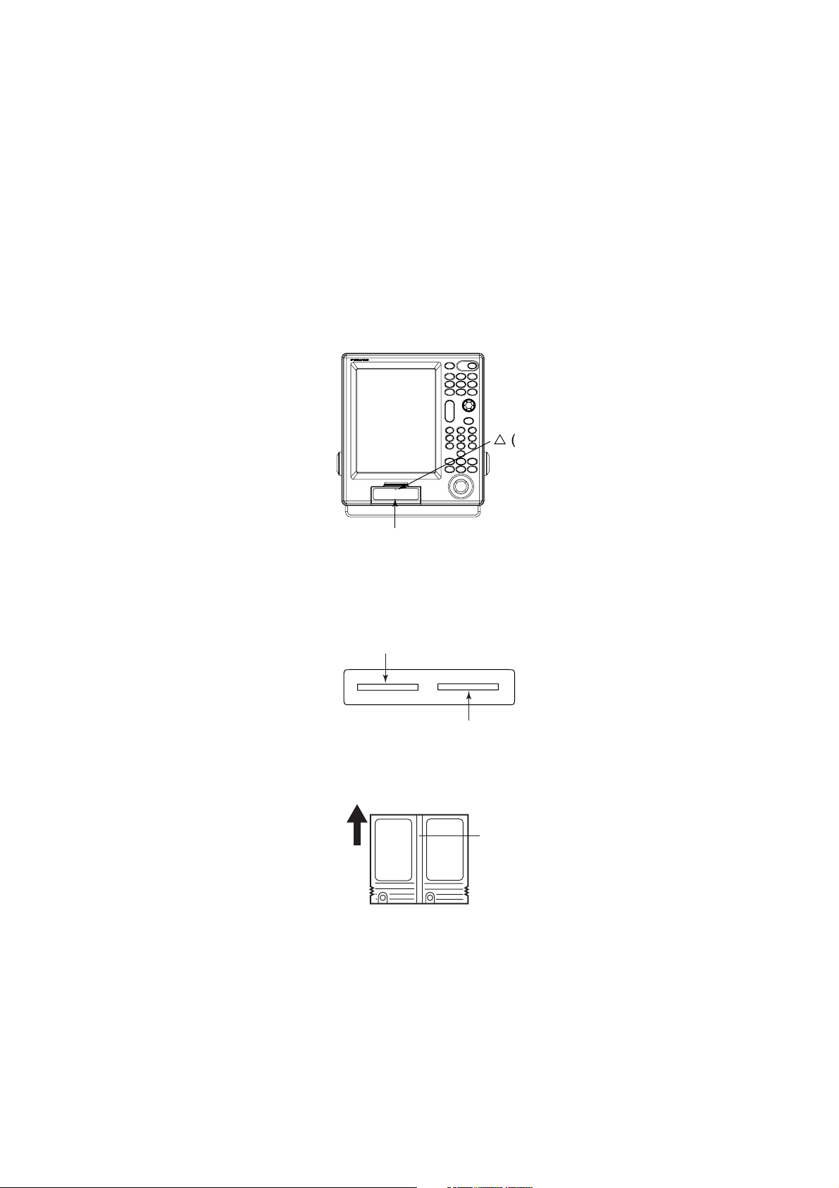
1.2 Loading a Mini Chart Card
Your unit reads FURUNO and NavCharts (NAVIONICS) chart cards, or C-MAP
chart cards, depending on the type of display unit you have. Insert the
appropriate chart card for your area before turning the power on to show chart
data automatically.
Note: Static electricity can be passed through your fingers to a card and destroy
the contents of the card. To prevent this, always touch a metallic object,
such as a steel desk, before handling a memory card.
1. Push down the lid catch to open the mini chart card slot cover.
r
(triangle) mark
1. BASIC OPERATION
r
COLOR GPS PLOTTER/SOUNDER
GP-3500F
Card slot
Card slot cover
2. Insert appropriate mini chart card groove side up to the right side slot.
Left-side: Memory card or Mini chart card
Right-side: Mini chart card only
Card slot
Inside chart card
groove side up.
Mini chart card
Chart card
3. Close the slot cover to protect the chart drive. (Keep the slot cover closed at
all times.)
Press the center of the lid catch to close it.
1-3
Page 14
1. BASIC OPERATION
1.3 Turning the Power On/Off
T urning the power on
Press the [P OWER] key until you hear a click and two beeps s ound.
When the unit is turned on, it proceeds in the sequence shown in the figure in
below.
GP-3500
GPS PLOTTER
FURUNO ELECTRIC CO. LTD.,
START UP TEST
PLOTTER
ROM : OK
RAM : OK
BACKUP DATA : OK
INTERNAL BATTERY : OK
INTERNAL GPS : OK
ECHO SOUNDER
ROM : OK
RAM : OK
--- CAUTION --NO NATIONAL HYDROGRAPHIC
OFFICE HAS VERIFIED THE
INFORMATION IN THIS
COASTLINE DATA CARD AND NONE
ACCEPT LIABILITY FOR THE
ACCURACY OF REPRODUCTION OR
ANY MODIFICATIONS MADE
THEREAFTER. THIS PRODUCT WITH
THIS COASTLINE DATA CARD
DOES NOT REPLACE THE
REQUIREMENT TO USE THE
APPROPRIATE PRODUCTS FOR
NAVIGATION ACCORDING TO
NATIONAL AND INTERNATIONAL
REGULATIONS.
CHART CARD. US603S32, US223S32
PROGRAM NO.
PLOTTER :
GPS :
1451712-XX.XX
48502640XX
C-MAP NT: 1451714-XX.XX
XX: Program Version No.
In about 30 seconds the lastused display appears. You
can go the last-used display
faster by pressing any key.
Start-up sequence
Note 1: The example screens sh own in this m anual may not match t he s c r eens
you see on y our display. The screen you see depends on your s ystem
configurat ion and equipment setti ngs.
Note 2: If the message "SYSTEM HAS FAILED START UP TEST. PLEASE
CONTACT A LOCAL FURUNO REPRESENTATI VE FO R REPAIR.
PRESS ANY KEY TO CONTINUE. " appears, contact y our dealer for
advice.
This equi pm ent takes about 90 seconds to f ind its position when turned on f or
the very first time. Thereafter it takes about 12 seconds to find position each time
the power is turned on. The message "NO FI X", which m eans the equipment is
mow fi ndings its posit ion, appears at the bottom of t he P lotter (or Pilot) display
immediately after turning the power on. When the GP S r ec eiver finds its position,
"NO FIX" c hanges to "2D" or "3D" to show that position dat a is now accurat e.
1-4
Page 15

1. BASIC OPERATION
Position-fixing indications and their meanings
Indication Meaning Indication Meaning
2D
2D
W2D
W3D
2D (dimension)
GPS position fix
3D (dimension)
GPS position fix
2D (dimension)
WAAS position fix
3D (dimension)
WAAS position fix
D2D*
D3D*
DEMO Simulation mode
2D (dimension)
DGPS position fix
3D (dimension)
DGPS position fix
*: The internal beacon receiver board (option) is necessary.
Note: If the password window appears, follow the procedure in paragraph 9.8.1.
Turning the power off
Press the [POWER] key.
After the turning power off, attach the LCD cover to prevent it.
1-5
Page 16

1. BASIC OPERATION
1.4 Adjusting Brilliance and Hue
You can adjust display brilliance, panel dimmer and hue as shown below.
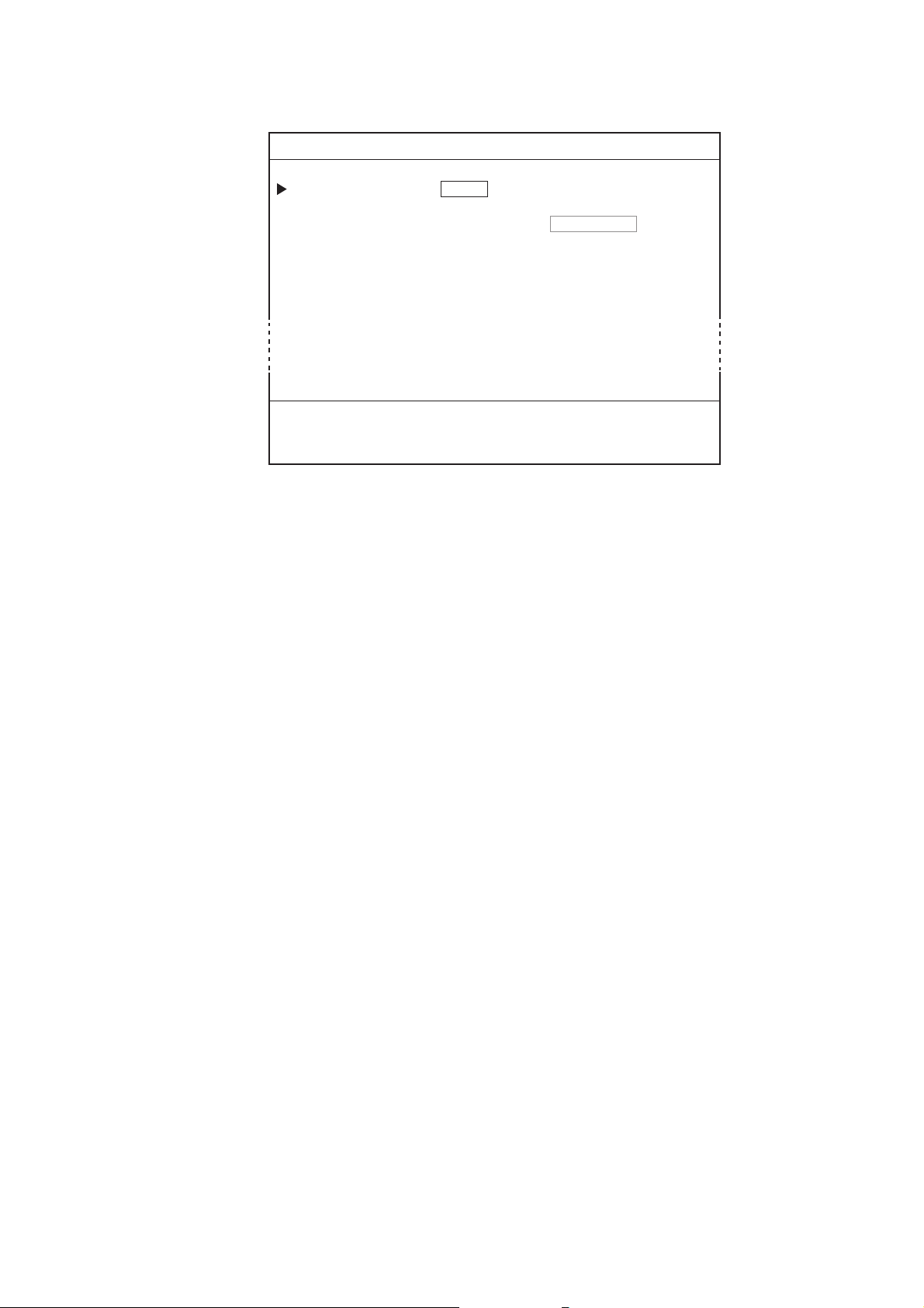
1.4.1 Adjusting display brilliance
1. Press the [BRILL] key.
The brilliance adjustment window appears.
BRILLIANCE 8
TURN KNOB TO ADJUST DISPLAY BRILLIANCE.
Brilliance adjustment window
Note: The adjustment window disappears when there is no operation for three
seconds.
2. Rotate the [ENTER] knob to adjust the brilliance.
Rotate clockwise to raise the setting or counterclockwise to decrease it (8 steps).
Also you can adjust brilliance by pressing the [BRILL] key. In this case brilliance
is changed cyclically 1→2
…→8→7→ …1→2….
3. Press the [ENTER] knob to manually close the adjustment window, or wait
three seconds to let the equipment close it automatically.
Note: The brilliance of an external monitor cannot be adjusted from the display
unit. Adjust it at the external monitor.
1-6
Page 17
1.4.2 Adjusting control panel dimmer
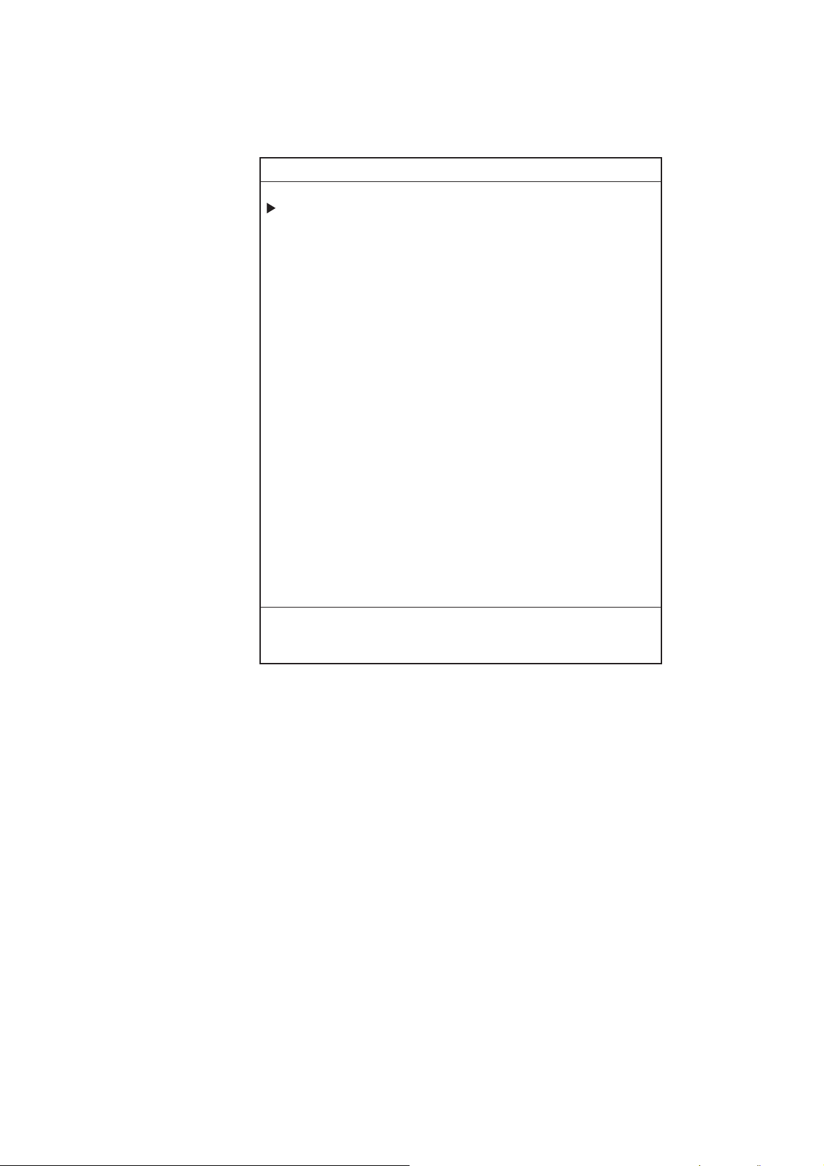
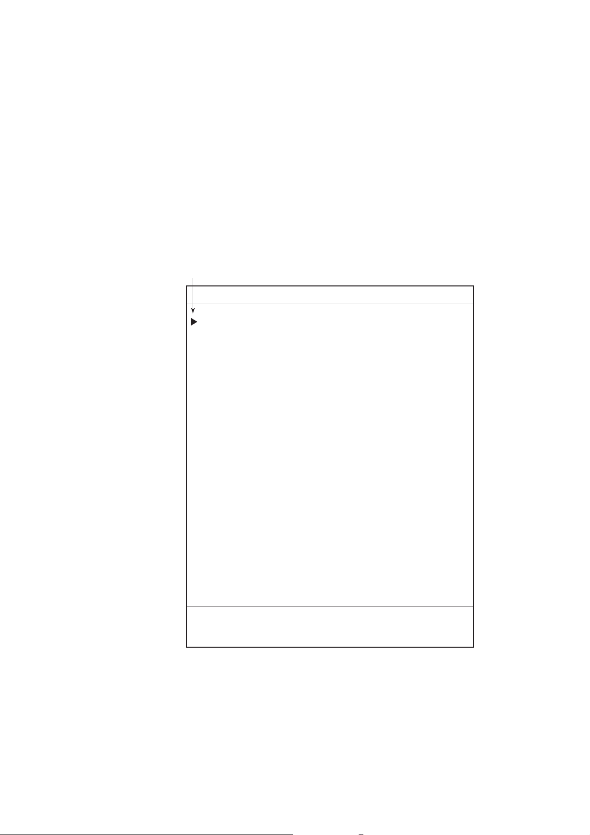
1. Press the [MENU] key to open the main menu.
MENU
1. WAYPOINT LIST
2. ROUTES LIST
3. MEMORY CARD OPERATIONS & DATA TRANSFER
4. MARKS/SHIP'S TRACKS SETUP
5. MARKS/SHIP'S TRACKS EDITION
6. ALARM SETUP
7. CHART SETUP
8. PLOTTER SETUP
1. BASIC OPERATION
9.
0. SYSTEM SETUP
TURN KNOB TO SELECT MENU AND PRESS KNOB TO ENTER.
OR PRESS APPROPRIATE NUMERIC KEY TO SELECT MENU.
Main menu
2. Press the [8] key to display the PLOTTER SETUP menu.
1-7
Page 18
1. BASIC OPERATION
8. PLOTTER SETUP
LORAN-A GRI 00-01
CORRECTION 1 +000.0 µs
CORRECTION 2 +000.0 µs
LORAN-C GRI 00:11-29
CORRECTION 1 +000.0 µs
CORRECTION 2 +000.0 µs
DECCA CHAIN 01 R-G
CORRECTION 1 +00.00 LANE
CORRECTION 2 +00.00 LANE
TD DISPLAY 1. LORAN-A 2. LORAN-C 3. DECCA
RESET TRIP LOG 1. YES 2. NO
PLOTTER RANGE SETUP
PANEL-DIMMER 1 2 3 4 5 6 7 8
HUE 1. DAY 2. NIGHT 3. TWILI 4. MANUAL
00:1L0 01:1L1 02:1L4 03:1L5 04:1L6
05:1L7 06:1S1 07:1S2 08:1S3 09:1S4
10:1S6 11:2H3 12:2H4 13:2H5 14:2H6
15:2S0 16:2S1 17:2S2 18:2S3 19:2S4
20:2S5 21:2S6 22:2S7
1. YES 2. NO
TURN KNOB TO SELECT MENU.
SELECT THE ITEM OF EACH MENU BY TRACKBALL.
Plotter setup menu
3. Rotate the [ENTER] knob to choose PANEL DIMMER.
4. Roll the trackball in the right-left direction to choose the illumination desired.
You may also choose the setting by pressing the appropriate numeric key.
The larger the number the greater the illumination.
5. Press the [MENU] key several times to close the menu.
1-8
Page 19
1.4.3 Selecting hue
1. Press the [MENU] key to display the main menu.
2. Press the [8] key to display the PLOTTER SETUP menu.
3. Rotate the [ENTER] knob to choose HUE.
4. Roll the trackball in the right-left direction to choose the hue desired. You may
also choose the hue by pressing the appropriate numeric key.
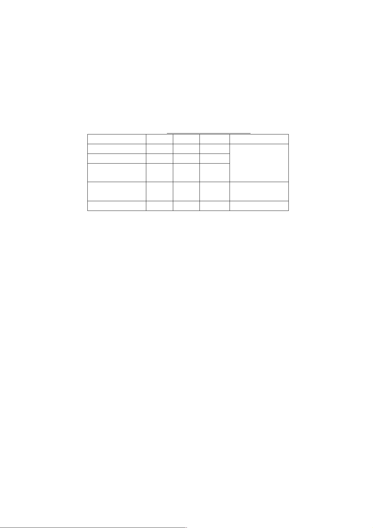
Refer to the table shown below the choose appropriate hue settings.
Day Night Twilight Manual
Landmass Yellow Yellow Yellow
Land edge Black Yellow Black
Background White Black Gray
Menu
background
Character Black White Black Black
5. Press the [MENU] key for several times to close the menu.
1. BASIC OPERATION
Hue setting and item color
Depending on
the setting of
CHART SETUP
menu
White Black Gray White
1-9
Page 20
1. BASIC OPERATION
1.5 Selecting a Display
Five screen displays are available: Plotter, Pilot, Navigation, Compass and
Sounder. In addition to the full-screen display, you can divide the screen into
half-screen combination displays.
1. Press the [DISP] key.
A DISPLAY MODE screen appears. There are four pages for the DISPLAY
MODE screen.
DISPLAY MODE
1. PLOTTER
4. PILOT 5. PILOT
7. COMPASS
PLOTTER
TURN KNOB TO SELECT DISPLAY MODE AND PRESS KNOB TO ENTER.
OR PRESS APPROPRIATE NUMERIC KEY TO SELECT DISPLAY MODE.
2. PLOTTER
NAV INFO 1
NAV INFO 1
8. COMPASS
PILOT
3. PLOTTER
NAV INFO 2
6. PILOT
NAV INFO 2
9. GPS STATUS
DISPLAY MODE screen
2. Press appropriate numeric key to choose a display.
Selected display replaces display made page
Note: The DISPLAY MODE screen can store a total of nine displays. You may
program the DISPLAY MODE screen as desired. See paragraph 9.6.1.
1-10
Page 21
1.6 MOB Mark
The MOB (Man Overboard) mark functions to mark man overboard position. You
can inscribe this mark from any mode, except while playing back, recording data
or conducting a self-test.
Man
overboard
Range, bearing
Current
position
MOB
mark
M
(MOB)
M
O
B
162.5°
0.49
M
nm
MOB data box
Bearing and range
to MOB position.
1. BASIC OPERATION
MOB concept
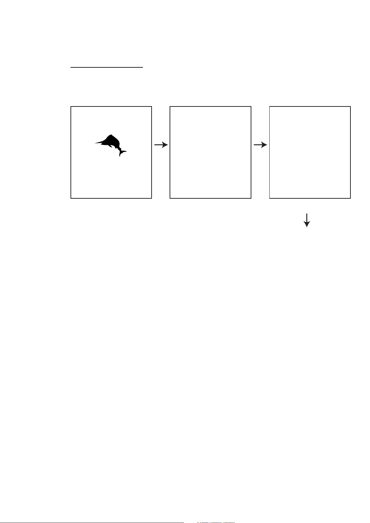
1. Press and hold down the [SAVE/MOB] key immediately for about three
seconds when someone falls onboard.
The display shows the waypoint number being saved (youngest empty waypoint
number) the MOB position is being saved under followed by the MOB
confirmation window.
WAYPOINT XXXXXX
IS SAVED.
CONTINUE PRESSING
FOR MOB!
After
several
seconds.
MAN OVER BOARD!
SET (MOB) AS
DESITINATION?
YES … PRESS KNOB
NO … PRESS CLEAR KEY
MOB mark messages
2. Push the [ENTER] knob to select the MOB position as the destination, or
press the [CLEAR] key to only mark current ship's position as a waypoint.
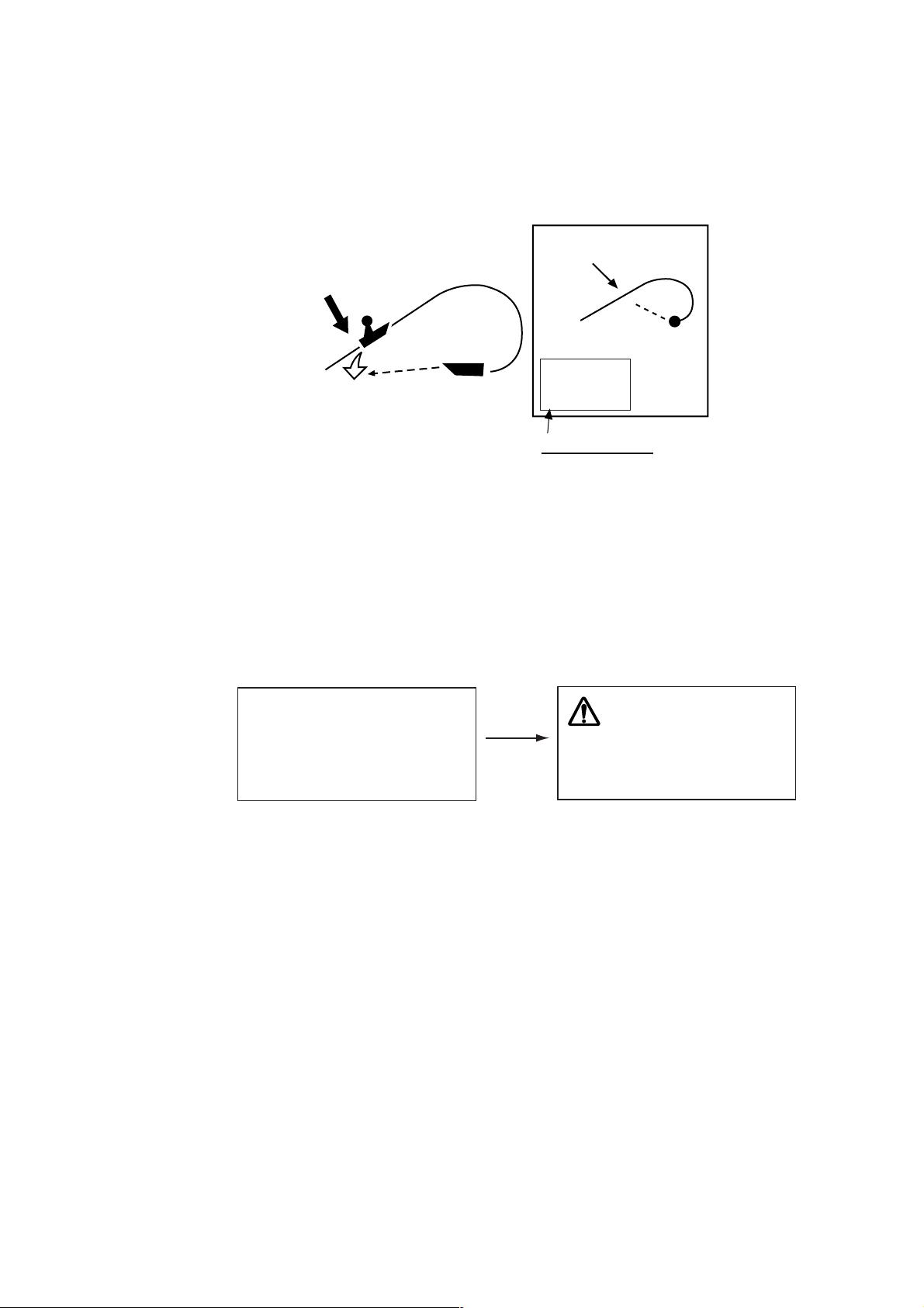
If you select the MOB position as the destination;
1) A full-screen PLOTTER NAV INFO 1 display replaces the display in use.
2) The MOB mark "M" appears at the MOB position and a dashed line runs
between it and current position. This line shows the shortest course to the
MOB position.
3) Range and bearing to the MOB position are shown in the MOB data box.
1-11
Page 22
1. BASIC OPERATION
Note: The MOB mark can be deleted as follows.
c Press the [CURSOR ON/OFF] key to show the cursor.
d Operate the trackball to place the cursor on the MOB mark.
e Press the [CLEAR] key.
f Press the [ENTER] knob.
g Operate the trackball to place the cursor on the MOB mark.
h Press the [CLEAR] key.
The following message will appear is on the screen:
WAYPOINT NAME XXXXXX
WILL BE DELETED.
ARE YOU SURE?
YES … PRESS KNOB
NO … PRESS CLEAR KEY
Confirmation message
Then, the waypoint entered at step 1 on the previous page is erased.
A new message will appear on the screen:
WAYPOINT NAME (MOB)
WILL BE DELETED.
ARE YOU SURE?
YES … PRESS KNOB
NO … PRESS CLEAR KEY
When MOB is not set as destination
Confirmation message
i Press the [ENTER] knob to erase the MOB mark.
1.7 Using PROG Key
The [PROG 1] through [PROG 4] keys provide for instant display of a
user-programmed options window (screen). Note that, the function for [VRM] key
can also be. The default program of the [PROG] keys are as shown in the table
below.
Key Functions
PROG 1 Displays the WAYPOINT LIST.
PROG 2 Displays DELETE SHIP’S TRACKS window.
PROG 3 Each press changes the line style.
PROG 4 Reset the trip distance to zero.
•Note 1: To program plotter functions to the [PROG] keys or [VRM] keys, see
paragraph 9.5.1.
THIS WAYPOINT (MOB)
IS USED FOR NAVIGATION.
ILL IT BE DELETED?
YES … PRESS KNOB
NO … PRESS CLEAR KEY
When MOB is set as destination
1-12
Page 23
1.8 Simulation Mode
The simulation mode, which is for use by service technicians for demonstration
purposes, provides simulated operation to help acquaint you with the many
features your unit has to offer. All keys are operative.
“DEMO” appears at the bottom of the plotter (pilot) display (top of the sounder
display) when any simulation mode is active.
Plotter
Own ship's mark moves from the default position at the speed set.
1. Press the [MENU] key to display main menu.
2. Press the [0] key to display SYSTEM SETUP menu.
0. SYSTEM SETUP
1. DISPLAY SETUP
1. BASIC OPERATION
2. NAVIGATOR SETUP
3. PROGRAMMABLE KEYS & REMOTE CONTROLLER SETUP
4. DISPLAY MODES & NAV DATA WINDOW SETUP
5. I/O PORT SETUP
6. TEST & MEMORY CLEAR
7. SIMULATION MODE
8.
TURN KNOB. TO SELECT MENU AND PRESS KNOB TO ENTER.
OR PRESS APPROPRIATE NUMERIC KEY SELECT MENU.
System setup menu
1-13
Page 24
1. BASIC OPERATION
3. Press the [7] key to display the SIMULATION MODE menu.
4. Rotate the [ENTER] knob to choose PLOTTER.
5. Roll the trackball in the left direction to choose "1. SIM." You may choose it
by pressing the [1] key.
6. Rotate the [ENTER] knob to choose SPEED.
7. Enter speed (setting range: 0.0 to 99.9 kt) with the numeric keys, then press
the [ENTER] knob.
8. Rotate the [ENTER] knob to choose COURSE.
9. Roll the trackball in the right-left direction to choose "1. DIRECTION" or "2. 8
FIGURE" as appropriate. You may choose the setting by pressing the
numeric key.
DIRECTION: Track is traced according to course set. Go to step 10.
8 FIGURE: Track is traced in a figure-eight course. Go to step 12.
10. Rotate the [ENTER] knob to choose DIRECTION.
11. Enter course (setting range: 0.0 to 359.9) with the numeric keys, then press
the [ENTER] knob.
12. Rotate the [ENTER] knob to choose LATITUDE.
13. Enter latitude with the numeric keys, and press the [ENTER] knob.
Press the [CURSOR ON/OFF] key to switch from north to south and vice
versa.
14. Rotate the [ENTER] knob to choose LONGITUDE.
15. Enter longitude with the numeric keys, and then press the [ENTER] knob.
Press the [CURSOR ON/OFF] key to switch from east to west and vice
versa.
16. Rotate the [ENTER] knob to choose DATE & TIME.
0-7. SIMULATION MODE SETUP
PLOTTER 1. SIM 2. LIVE
SPEED 09.9 kt
COURSE 1. DIRECTION 2. 8 FIGURE
DIRECTION 000.0°
LATITUDE 45°35.000'N
LONGITUDE 125°00.000'W
DATE & TIME 03.01.01 00:00
TURN KNOB TO SELECT MENU.
SETUP SIMULATION MODE BY TRACKBALL.
Simulation mode setup menu
1-14
Page 25
17. Enter start date and time with the numeric keys, in 24-hour notation and then
press the [ENTER] knob.
Use 24-hour notation to enter time.
18. Press the [MENU] key several times to close the menu.
Note: To terminate the simulation mode, select "2. LIVE" at step 5.
1.9 Menu Overview
Secondary operations are carried out through the menu. This section provides
basic menu operating information.
1. Press the [MENU] key to display the main menu.
Red cursor
MENU
1. BASIC OPERATION
1. WAYPOINT LIST
2. ROUTES LIST
3. MEMORY CARD OPERATIONS & DATA TRANSFER
4. MARKS/SHIP'S TRACKS SETUP
5. MARKS/SHIP'S TRACKS EDITION
6. ALARM SETUP
7. CHART SETUP
8. PLOTTER SETUP
9.
0. SYSTEM SETUP
TURN KNOB TO SELECT MENU AND PRESS KNOB TO ENTER.
OR PRESS APPROPRIATE NUMERIC KEY TO SELECT MENU.
Main menu
1-15
Page 26
1. BASIC OPERATION
2. Select a menu item.
There are three ways to select a menu item. This manual uses method a).
a) Press the appropriate numeric key.
b) Rotate the [ENTER] knob to select the menu item desired, and then press the
[ENTER] knob.
The red cursor appears at left side of the item selected. Rotate the [ENTER]
knob clockwise to move the red cursor upward; counterclockwise for
downward.
c) Roll the trackball in up-down direction to select item, and then press the
[ENTER] knob.
For example, press the [8] key to display the PLOTTER SETUP menu.
Cursor (red rectangle)
8. PLOTTER SETUP
LORAN-A GRI 00-01
CORRECTION 1 +000.0 µs
CORRECTION 2 +000.0 µs
LORAN-C GRI 00:11-29
CORRECTION 1 +000.0 µs
CORRECTION 2 +000.0 µs
DECCA CHAIN 01 R-G
CORRECTION 1 +00.00 LANE
CORRECTION 2 +00.00 LANE
TD DISPLAY 1. LORAN-A 2. LORAN-C 3. DECCA
RESET TRIP LOG 1. YES 2. NO
PLOTTER RANGE SETUP
PANEL-DIMMER 1 2 3 4 5 6 7 8
HUE 1. DAY 2. NIGHT 3. TWILI 4. MANUAL
00:1L0 01:1L1 02:1L4 03:1L5 04:1L6
05:1L7 06:1S1 07:1S2 08:1S3 09:1S4
10:1S6 11:2H3 12:2H4 13:2H5 14:2H6
15:2S0 16:2S1 17:2S2 18:2S3 19:2S4
20:2S5 21:2S6 22:2S7
1. YES 2. NO
1-16
TURN KNOB TO SELECT MENU.
SELECT THE ITEM OF EACH MENU BY TRACKBALL.
Plotter setup menu
3. Rotate the [ENTER] knob to select item which you want to change the setting.
You can also select item by rolling the trackball in up-down direction.
4. Roll the trackball in left-right direction to select option (with the red rectangle).
When the option is a numeral, you can select it by pressing the appropriate
numeric key.
5. Press the [MENU] key several times to close the menu.
Page 27
1. BASIC OPERATION
Entering numeric data
Cursor
8. PLOTTER SETUP
LORAN-A GRI 00-01
CORRECTION 1 +000.0 µs
CORRECTION 2 +000.0 µs
TURN KNOB TO SELECT MENU.
SELECT THE ITEM OF EACH MENU BY TRACKBALL.
Plotter setup menu
1. Press the appropriate numeric key.
2. Press the [ENTER] knob.
You may also enter a value rotating the by [ENTER] knob.
Note: If you make a value mistake, move the cursor to the error position and
then re-enter the proper value. The cursor for entering value is moved by
rolling the trackball in left-right direction.
Press the [CLEAR] key to erase the all value on the line selected with the
red cursor.
1-17
Page 28

1. BASIC OPERATION
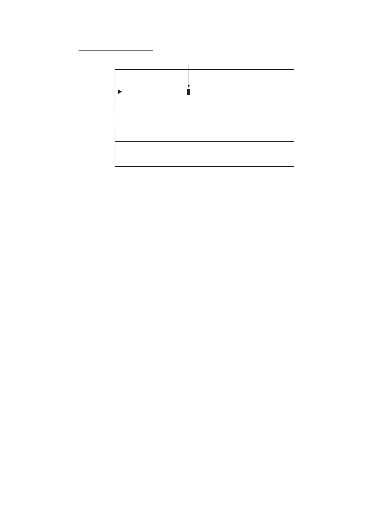
Entering character
1. Roll the trackball in up-down direction to select the first alphanumeric
character with the cursor (red square).
Numeric may also be entered by pressing numeric key.
2. Press the [ENTER] knob.
Note: If you make a characteristic mistake, move the cursor to the error position
and then re-enter the proper character. To move the digit cursor, select ◄
and then press the [ENTER] knob for left direction, or select ► and then
press the [ENTER] knob for right direction.
Press the [CLEAR] key to erase the all characters.
3. Repeat steps 1 and 2 to complete the naming.
4. Finally, select "END" and then press the [ENTER] knob.
Digit cursor Cursor
PASSWORD ENT AGAIN
END
ABCDE FGHIJ KLMNO PQRST UVWXY
Z,-!? /&^=# 12345 67890 _____
abcde fghij klmno pqrst uvwxy
z____ _____ _____ ______ _ _ _
SELECT ALPHANUMERIC CHARACTER BY TRACKBALL AND PRESS KNOB
TO ENTER. OR PRESS NUMERIC KEY TO NAME WAYPOINT.
MOVE THE CURSOR TO "END" ONCE THE EDITION IS FINISHED.
Ex. Set password, entering characters
1-18
Page 29
2. PLOTTER AND PILOT DISPLAY
DESCRIPTION
2.1 Plotter and Pilot Displays
The plotter and pilot displays can be shown with full- s c r een or in a half screen
combined with the nav information w indow , compass or echo s ounder display.
Press the [DISP] key, and then press the appropriate numeric key to s how the
display desired.
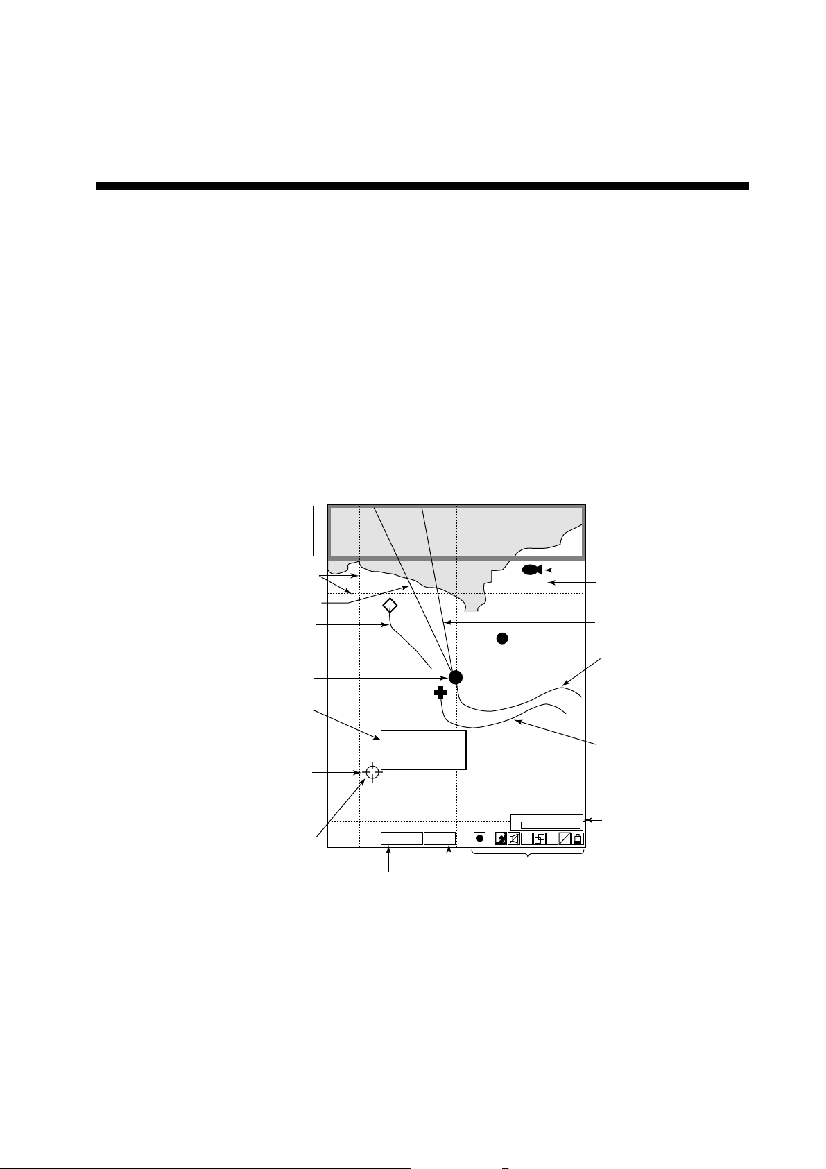
2.1.1 Plotter display
The plotter display shows chart data, tracks, waypoints and marks on the display.
The plotter display orientation is always north-up. North (zero degree) is at the
top of the di s play and own ship (filled circle) is at the cent er of the screen.
When selecting PLOTTER
NAV INFO 1 (or 2),
NAV INFO window appears here.
Grid
Heading marker (white)
Other ship's track
Own ship's mark
Mark information
(appears when
the cursor is on
a mark)
Cursor
Mark
43
20 21 22
000001
42
37˚04.640'N
135˚21.047'E
+ 4.5˚C 13.7m
41
WGS84
GPS2D
GPS/DGPS
status
Geodetic
datum
Icons
PLOTTER display
FISH
H
0.3nm
S A
V E
Waypoint mark
Waypoint name
Course bar (light-blue)
Own ship's track (main)
Own ship's track (sub)
Scale
L
L
2-1
Page 30
2. PLOTTER AND PILOT DISPLAY DESCRIPTION
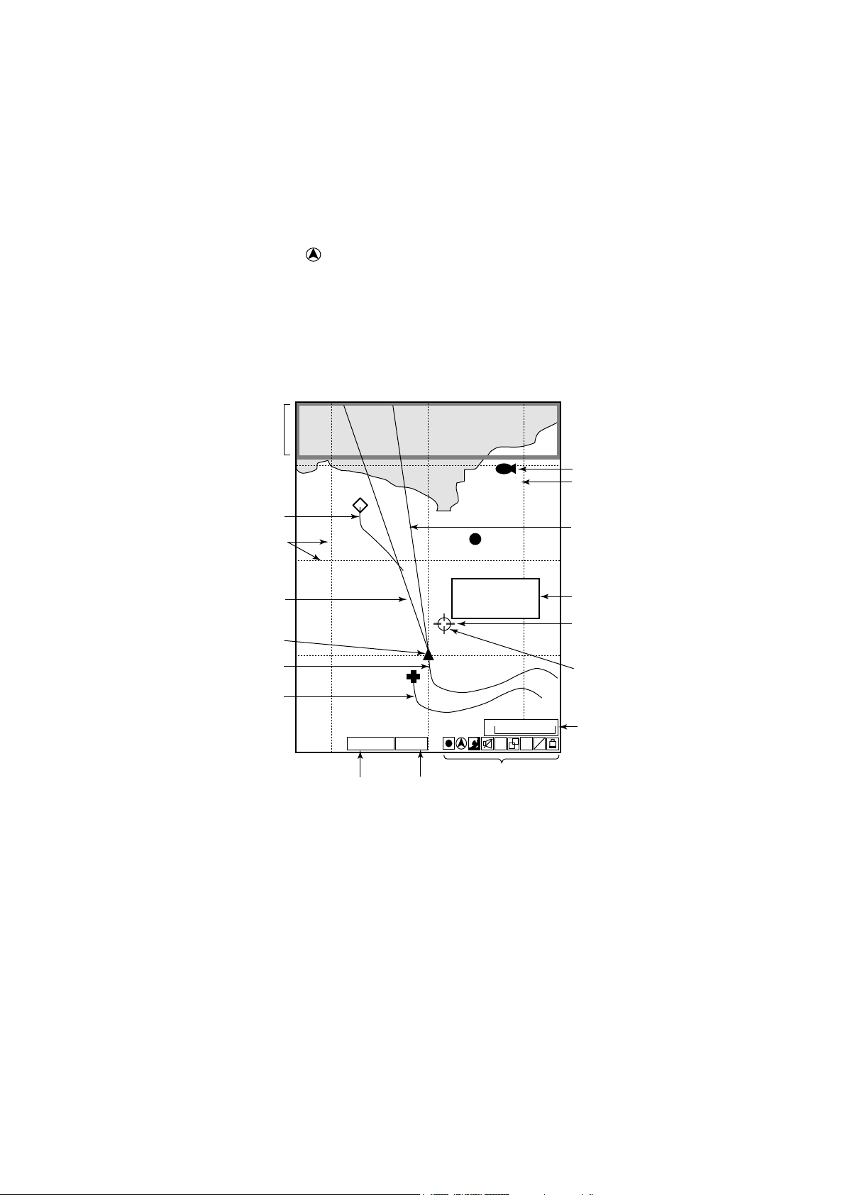
2.1.2 Pilot display
The pilot display is similar to the plotter display, with the following differences.
1) The pilot display orientation is always auto course-up. The course is at the
top of screen at the moment the pilot display is selected. A filled triangle
marks own ship’s position. When own ship is off its intended course by 22.5°
or more, it is automatically brought back to perpendicular.
2) The north mark (
3) The grid lines denote the distance from own ship, not longitude/latitude.
Note: When north is not at the top of screen, the distance error may be larger
than on the plotter display since the Mercator projection is used.
When selecting
PILOT NAV INFO 1 (or 2),
the NAV INFO window
appears here.
) appears at the bottom of the screen and points to north.
1
FISH
Waypoint mark
Waypoint name
Other ship's track
Grid
Heading marker (white)
Own ship's mark
Own ship's track (main)
Own ship's track (sub)
0.5
GPS2D
GPS/DGPS status
000001
0.5
37˚03.640'N
135˚20.047'E
+ 4.5˚C 13.7m
WGS84
0.5
Geodetic datum
Pilot display
H
Icons
0.5
0.2nm
S A
V E
Course bar (light-blue)
Mark information
Cursor
Mark
Scale
L
L
2-2
Page 31

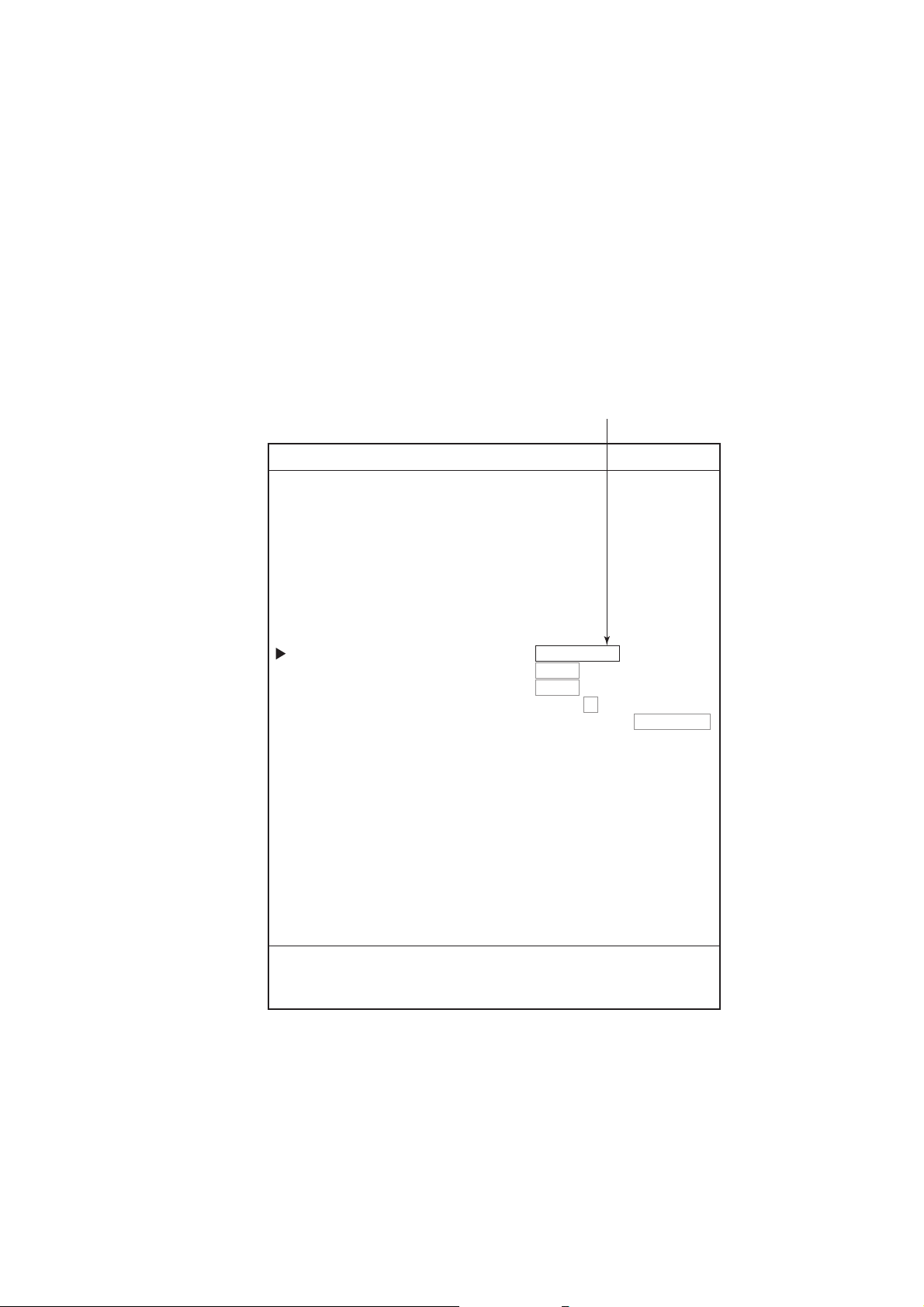
2.1.3 NAV INFO 1 display
Select “PLOTTER (or PILOT) NAV INFO 1 (or 2)” from the DISPLAY MODE
screen to show the NAV INFO 1(or 2) window at the top of the screen. When
setting a destination, the NAV INFO 1 (2) window changes to the WPT INFO 1
(2) window.
This color shows the
selected mark color.
Black means the selection
of "KEY'S COLOR."
(See paragraph 4.2.)
2. PLOTTER AND PILOT DISPLAY DESCRIPTION
Speed over ground
Latitude, Longitude
34 44.1447'N
135 21.0758'E
9.9
350.2
Track plottings interval
TRKS 00M01s
kt
2003. 4. 12
00:01
T
Date
NAV INFO 1 window (Default data)
Latitude, Logitude
34 44.1447'N
135 21.0758'E
NAV INFO 2 window (Default setting)
Latitude, Longitude
3444.1447'N
21.0758'E
135
000001
Waypoint Name
0.60
Speed over ground
9.9
350.2
L/L of cursor position
34 43.1447'N
+
135 21.0758'E
284.2
nm
Bearing to Waypoint
ETA 1, 3:19
T
TTG 0D 0H 4M
TimeCourse
L/L of
cursor position
+
34 43.1447'N
kt
135 21.0758'E
00:01
T
TimeCourse
Estimated time of arrival
at Wa ypoint
Time-to-Go to destination
Range to Waypoint
NAV INFO 1 window on setting a destination (default data)
2-3
Page 32

2. PLOTTER AND PILOT DISPLAY DESCRIPTION
Latitude, longitude
34 44.1447'N
135 21.0758'E
Speed over ground
Course
SOG 9.9kt
COG 350.2 T
DPT 16.2 m
TEMP 5.3 C
2003. 4. 13
00:01
TRIP 0nm
TRKS 00M01s
Depth
Date
Time
Trip distance
Tracking interval
NAV INFO 2 wi ndow on setting a des tination (default data)
Note: You can choose the data t o display in the NAV. INFO windows . F or
further details, s ee paragraph 9.6. 2.
2.1.4 Compass plotter (or pilot) display
The compass display, displayed at the top of the screen in a combination display,
provides st eering informat ion.
Range to destination waypoint
Destination waypoint
Time-to-go
to destination
Bearing to destination
waypoint (black)
Depth graph
(Required depth data.)
000001
TTG
0D 9H 59M
DEPTH
14. 9 m
Speed over ground
RANGE
SOG
BRG TO WPT
359.9˚M
w
COG
359.9˚M
N
5
25
0.43
9. 9
kt
ETA
E
Water temp.
Speed through water
nm
STW
1st 23 : 59
TEMP
10
0
10. 5
4. 9˚C
Estimated time of
kt
arrival at destination
Ship's course (red)
Water temperature graph
(Required water temperature data.)
Shown in red when
direction to steer
is left.
Bearing scale
XTE monitor
Compass display
Direction to steer (green)
Own ship mark
(Black when the ship is within
XTE range, yellow when over.)
2-4
Page 33

2. PLOTTER AND PILOT DISPLAY DESCRIPTION
Compass indicator
The black inverted triangle shows the bearing to the destination waypoint, and
the red triangle shows own ship’s course.
Note: The course means the direction of own ship’s movement, it is not the
direction of heading. The cursor includes the affect of current and wind.
Depth and water temperature graphs
The depth and water temperature graphs, which require appropriate sensors,
show the latest 10 minutes of depth and water temperature data. The range of
the depth graph is 50 feet and it is automatically adjusted with depth.
XTE (cross-track error) monitor
The black boat-shaped (own ship mark) mark shows ship’s cross-track from the
intended course and direction, and amount to steer to return to course. It is
shown in black when the amount of cross-track error is within the XTE monitor
range and yellow when it is over. An arrow appears at the right or left side of the
XTE monitor and it shows the direction to steer to return to the intended course.
The arrow is shown in red when you should steer left, and green when you
should steer right. In the example on the previous page you would steer right to
return to course set. To maintain course, steer the vessel so the own ship marker
stays at the center of the XTE monitor.
2-5
Page 34

2. PLOTTER AND PILOT DISPLAY DESCRIPTION
2.1.5 GPS status display
The GPS status display provides data about the GPS satellites and GEO
satellite (for WAAS).
Estimated position of satellite in the sky.
Satellites used for fixing position are circled.
Receiving signal level
Bars show satellite
signal levels. Satellites
whose signal level
extends 40 are used
to fix position.
N
08
05
12
01
06
30
03
S
SAT
No.
30 40 50
21
07
06
11
03
05
12
08
20
28
30
01
123
SNR
WAAS satellite (GEO)
GPS status display
01 : 00 : 15
21
07
11
W
APR 1 2003
20
EW
28
GPS 2D
DOP
ALT
FREQ
SS
SN
Appears when the
internal DGPS beacon
receiver is installed.
Time
Date
GPS fix status
DOP value
1. 2
GPS antenna height
12 m
DGPS beacon frequency
310.0 kHz
Signal strength
75.0 dB
22.0 dB
DOP value: DOP stands for Dilution of Precision and is an indication of the
quality of the satellite constellation. The smaller value means the
higher accuracy. (For your reference, the positioning accuracy is
approx. 10 m when the value is less than “4”.)
SS: SS (Signal Strength) displays a numeric representation of electrical field
strength of the received signal on the selected frequency. The higher the
number the stronger the received signal, and a figure above 60 is normal.
SN: SN (Signal-to-Noise) ratio displays the ratio between the desired signal
and unwanted noise on the selected frequency. The higher the SN ratio the
better the quality of the signal, and a figure above 21 is normal.
2-6
Page 35

2. PLOTTER AND PILOT DISPLAY DESCRIPTION
2.2 Operating the Cursor
1. Press the [CURSOR ON/OFF] key.
The cursor is turned on, and the cursor appears at the own ship’s position. To
hide the cursor, press the [CURSOR ON/OFF] key again.
Cursor position in L/L
kt
43
000001
TRKS HOLD
2003. 4. 1
00:01
T
FISH
22
Cursor
34 43.1447'N
+
135 21.0758'E
20 21
9.9
350.2
PLOTTER NAV INFO 1 display (appearing the cursor)
2. Operate the trackball.
The cursor moves in the direction the trackball is operated and the cursor
position is indicated at the top of the screen.
Note: The chart display moves in the opposite direction when it reaches an edge
of the screen.
To return the cursor to the screen center
▪ Press the [CENTER] key to return the cursor to the screen center.
2-7
Page 36

2. PLOTTER AND PILOT DISPLAY DESCRIPTION
2.3 Shifting the Display
The display can be shifted on the plotter display and pilot display.
1. If the cursor is turned on, press the [CURSOR ON/OFF] key to turn it off.
2. Operate the trackball.
The display shifts in the direction which the trackball is rolled.
3. Press the [CENTER] key to return the own ship position to the screen center.
(On the pilot display, the own ship’s mark is positioned slightly below the
center of the screen.)
Note: When own ship reaches an edge of the screen, it is returned to the
center of the screen automatically.
2.4 Changing Chart Scale
It is useful to change chart scale to
• Show destination on the display
• Find how close you are to your destination
• View ship’s tracks around a fishing ground
When cursor is off
Own ship is at the screen center. The display is enlarge or shrunk from the
screen center.
When cursor is on
The range scale is enlarged or shrunk with the cursor position as center.
• Press the [ZOOM IN] key to enlarge the scale, or [ZOOM OUT] key to shrink.
After pressing the [ZOOM IN] or [ZOOM OUT] key, the current range appears
at the center of the screen for a second. The range value shows the distance
between the left-side and right-side edges of the screen.
Ranges (default setting)
0.125 0.25 0.50 0.75 1.00 1.50 2.00 3.00 4.00 6.00
8.00 12.0 16.0 24.0 32.0 48.0 72.0 96.0 128 256
512 1024
(The larger value may be different from the above depending on latitude of own
ship.)
Note 1: When the display is expanded or shrunk beyond the range of the chart
card in use warning icon appears, along with the appropriate chart icon.
See paragraph 2.7.
Note 2: You can choose the ranges to use. See paragraph 9.2.3.
Note 3: The width of the screen can be shown with scales instead of the
distance. See paragraph 9.3.
2-8
Page 37

2. PLOTTER AND PILOT DISPLAY DESCRIPTION
2.5 Measuring Range and Bearing Between tw o
Points
You can measure the range and bearing between two points as follows.
1. If the cursor is turned on, press the [CURSOR ON/OFF] key to turn it off.
2. Press the [0] key.
The “X” mark is entered at the own ship’s position at the moment the [0] key is
pressed, and a data box appears at the top of the display.
Data box
RULER 0.00nm 0.0 T
FISH
43
"X" mark
20 21
000001
×
22
Data box
3. Use the trackball to place the cursor on the starting point.
When the cursor is moved, a dashed circle appears, with the “X” mark at its
center and a dashed line intending from the “X” mark to the cursor.
4. Press the [ENTER] knob, and the “+” mark moves to the cursor position.
5. Use the trackball to place the cursor on the ending point.
The data box shows range and bearing between the starting and ending points.
2-9
Page 38

2. PLOTTER AND PILOT DISPLAY DESCRIPTION
Range and bearing
between starting and ending points
RULER 0.61nm 90.1 T
FISH
43
20 21
000001
X
22
Ending point
(Cursor)
Starting point
(X mark)
41
GPS2D
WGS84
GPS2D
Range and bearing between two points
0.3nm
6. Press the [0] key to terminate the measurement and erase the dashed circle
and line, and data.
2-10
Page 39

2. PLOTTER AND PILOT DISPLAY DESCRIPTION
2.6 Using the VRM (Variable Range Marker)
The VRM function to measure the distance between two points, like using
dividers to measure distance on a nautical chart.
1. Press the [VRM] key to show the VRM.
Each pressing this key makes the sequence shown below.
VRM off → VRM (floating VRM) → VRM (fixed VRM) → VRM off …
VRM off: VRM is turned off.
VRM (floating VRM): You can adjust its position and radius.
VRM (fixed VRM): VRM is fixed at position selected with floating VRM. Its radius
is also fixed.
When cursor is turned on, VRM appears around it. When cursor is turned off,
VRM appears around own ship’s position. Also, a data box appears at the top of
the display to show the radius of VRM.
Cursor
VRM
(Yellow)
Radius of VRM
0.27nm
20 21
GPS2D
WGS84
VRM
43
000001
42
41
FISH
22
0.3nm
2. Use the trackball to place the VRM where desired.
3. Rotate the [ENTER] knob to adjust the radius of VRM.
Clockwise rotation: Increase radius.
Counterclockwise rotation: Decrease radius.
2-11
Page 40

2. PLOTTER AND PILOT DISPLAY DESCRIPTION
4. When it is not necessary to change the VRM’s location and size, simply
press the [ENTER] knob.
VRM is fixed at the selected position.
5. To turn off the VRM, press the [VRM] key to hide VRM.
The data box disappears immediately.
Note: The [VRM] key’s default function is to turn the VRM on and off. Its function
can be changed as desired. For details, see paragraph 9.5.1.
2.7 Mini Chart Cards
This equipment uses both FURUNO and NAVIONICS chart cards or C-MAP NT
mini chart cards depending on its specifications. When you insert a suitable
chart card in the right side slot and turn on the power, a chart appears. If a
wrong card is inserted or a wrong chart scale is selected, landmasses will be
hollow. Insert the proper card and select a suitable chart scale. Chart icons
appear at the bottom of the plotter (or pilot) display to help you select a suitable
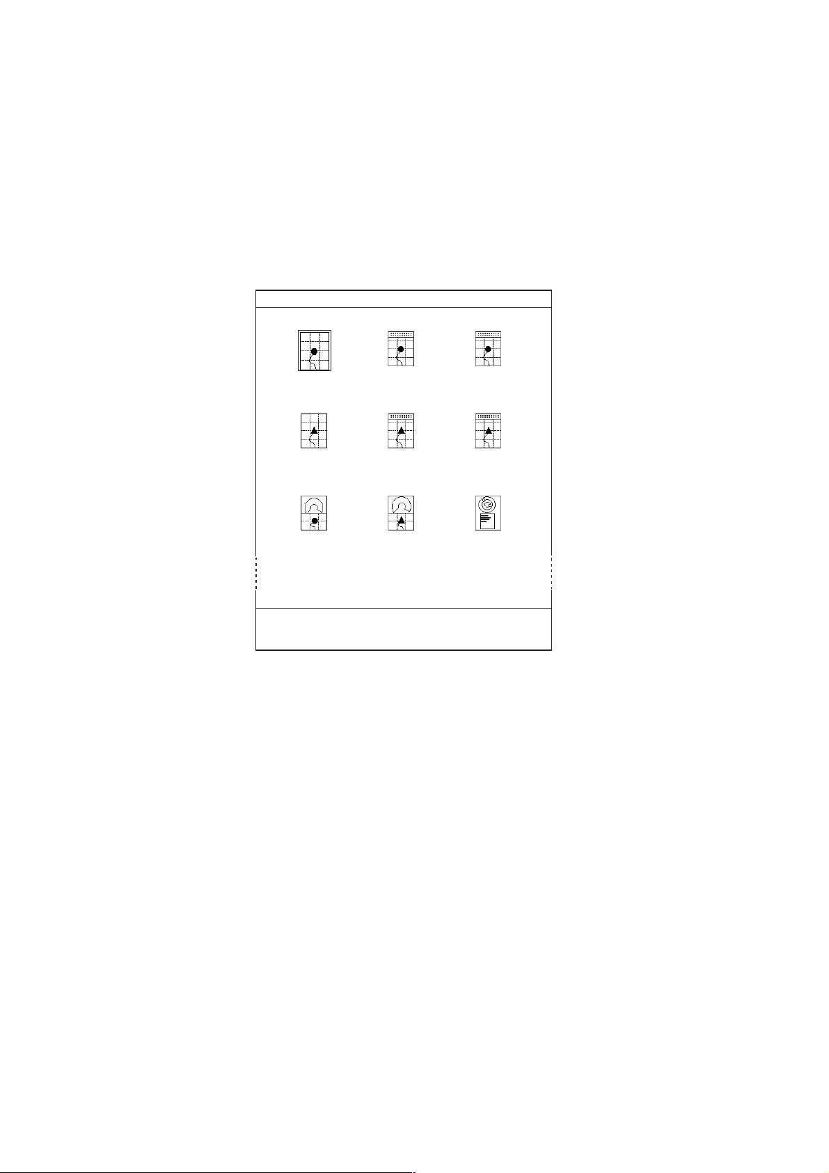
chart size. The table below shows the chart icons and their meanings.
Chart icons and their meanings
Icon Meaning
Proper card is not inserted or
chart scale is too small.
Operate the [ZOOM IN] key to
adjust chart scale.
Chart scale is too large.
Operate the [ZOOM OUT] key to
adjust chart scale.
Suitable chart scale is selected.
2-12
Page 41

Indices and chart enlarg ement
When the [ZOOM OUT] key is used, you will see several frames appear on the
chart. These frames are called indices and they show you what parts of the chart
can be zoomed. The areas circumscribed with smaller frames can show more
detailed information.
Tide information
2. PLOTTER AND PILOT DISPLAY DESCRIPTION
Indices
The C-MAP NT chart card provides for calculation of the tide heights for any
date. Additionally it displays the times of sunrise and sunset.
1. Operate the trackball to place the cursor on a Tide icon.
T
Tide icon
2. Press the [ENTER] knob to open the OB JECT window.
OBJECT
Tide height
Depth area
Harbour area
(administrative)
Source of data
Object window
3. Rotate the [ENTER] knob to select “Tide height.”
4. Press the [ENTER] knob to open the tide window.
2-13
Page 42

2. PLOTTER AND PILOT DISPLAY DESCRIPTION
4.66
3.97
3.28
2.60
1.91
0 4 8 12 16 20 24
TIME: 12:00
HEIGHT: 2.23 ft
DRAUGHT:3.28 ft
04/11/03 +09
34 38. 913' N
135 26. 051' E
PORT INFORMATION
OSAKA KO
HIGH WATER (MAX)
4.66 ft (17:07)
LOW WATER (MIN)
1.91 ft (10:15)
SUNRISE 06:21L
SUNSET 17:01L
TIDE window
5. Press the [ENTER] knob to show the CHANGE DATE window.
CHANGE DATE
(DD. MM. YYYY.)
04. 11. 2003
LIMIT: 31. 12. 2099
DATE window
6. Operate the trackball to position the cursor to the digit to change, and then
press the numeric keys to enter a date.
7. Press the [ENTER] knob to show the tidal graph for entered date.
8. Roll the trackball in left-right direction t o locate the vertical cursor on the time
desired. Time and height are shown below the graph.
9. Roll the trackball in upward-downward direction to shift the level cursor.
Draught is shown to the left of the graph.
10. Press the [MENU] key to close the TIDE window.
2-14
Page 43

3. TRACK
Your ship’s track (main and sub tracks) is plotted on the screen using navigation
data fed from the built-in GPS navigator. When connecting with an
ARPA-equipped radar, other ship’s track can also be plotted. This chapter shows
you how to turn track on or off, and change its color and plotting interval. Own
ship’s track is displayed in red in the default setting.
Own ship's track (sub)
Own ship's track (main)
3.1 Displaying Track
3.1.1 Own ship’s track
Own ship’s track can be turned on or off as follows.
1. Press the [MENU] key to display the main menu.
2. Press the [4] key to open the 4. MARKS/SHIP’S TRACKS SETUP menu.
This menu has two pages. If PAGE 2/2 appears, rotate the [ENTER] knob
clockwise to select “PREVIOUS PAGE.”
3. Rotate the [ENTER] knob to choose “SHIP’S TRACKS DISP.”
Tracks
Other ship's track
3-1
Page 44

3. TRACKS
4. MARKS/SHIP'S TRACKS SETUP PAGE 1/2
NEXT PAGE
MARKS SIZE 1. L 2. L+ 3. S
LINES STYLE 1. 2. 3. 4.
TRACK INTERVAL 1 TIME (00M10s) DIST (0.10nm)
TRACK INTERVAL 2 TIME (00M10s) DIST (0.10nm)
SHIP'S TRACKS DISP 1. ON 2. OFF
DISP TRACKS (HOLD) 1. ON 2. OFF
PLOT TRACKS (HOLD) 1. ON 2. OFF
TRACKS COLOR 1. 2. 3. 4.
TRACKS BY TEMP RANGE GRDNT (0.2˚F 2.0˚F)
WHITE: 005.0˚F BELOW
BLUE: 005.0˚F ~
PURPLE 010.0˚ F ~
LIGHT BLUE: 012.5˚F ~
GREEN: 015.0˚F ~
YELLOW: 017.5˚ F ~
RED: 020.0˚F ABOVE
TRACKS BY DEPTH RANGE GRDNT (2ft 20ft 200ft)
WHITE: 0032.8 ft SHALLOWER
BLUE: 0032.8 ft ~
PURPLE 0164.0 ft ~
GREEN: 0656.2 ft ~
YELLOW: 0984.3 ft ~
RED: 1312.3 ft DEEPER
SHIP'S TRACKS 12,000
MARKS 04,000/16,000
TURN KNOB TO SELECT MENU.
SELECT THE ITEM OF EACH MENU BY TRACKBALL.
Marks/ship’s tracks setup menu (page 1)
4. Press the [1] key to choose ON or the [2] key to choose OFF as appropriate.
5. Press the [MENU] key several times to close the menu.
Note: The number of track points used appears at the bottom of the
MARKS/SHIP’S TRACKS EDITION menu. (See page 3-16.)
3-2
Page 45

3.1.2 Sub track
A second track of own ship’s track, called sub track, may be shown, using data
from a second navigator.
Note that the sub track is not stored in the memory; it is erased when it goes off
the screen or when the power is turned off.
1. Press the [MENU] key to display the main menu.
2. Press the [4] key to show the MARKS/SHIPS TRACKS SETUP menu.
3. If PAGE 1/1 appears, rotate the [ENTER] knob clockwise to select “NEXT
PAGE to show page 2/2.”
4. Rotate the [ENTER] knob to choose “DISP SUB TRACKS.”
4. MARKS/SHIP'S TRACKS SETUP PAGE 2/2
PREVIOUS PAGE
DISP T ARGET TRACKS
TARGET TRACK COLOR
T ARGET TRACK STYLE
DISP SUB TRACKS 1. ON 2. OFF
SUB TRACK COLOR 1. 2. 3. 4. 5. 6. 7.
SUB TRACK STYLE 1. 2. 3. 4.
SUB TRACK TALKER 1.GP 2.II 3.IN 4.SN 5.TR
3. TRACKS
1. ON 2. OFF
1. 2. 3. 4. 5. 6. 7.
1. 2. 3. 4.
6.LA 7.LC 8.DE 9.EC
TURN KNOB TO SELECT MENU.
SELECT THE ITEM OF EACH MENU BY TRACKBALL.
Marks/ship’s tracks setup menu (page 2)
5. Press the [1] key to choose ON or the [2] key to choose OFF as appropriate.
6. Press the [MENU] key several times to close the menu.
Note: The position data used to trace the sub track may be chosen with “SUB
TRACK TALKER” on page 2 of the MARKS/SHIP’S TRACKS SETUP
menu. For further details, refer to the installation manual.
3-3
Page 46

3. TRACKS
3.1.3 Other ship’s track
You may show the tracks of ARPA targets tracked in auto tracking. Note that this
track is not stored in the memory; it is erased when it goes off the screen a when
the power is trued off
1. Press the [MENU] key to display the main menu.
2. Press the [4] key to show the MARKS/SHIP’S TRACKS SETUP menu.
3. If PAGE 1/1 appears, rotate the [ENTER] knob clockwise to select “NEXT
PAGE.”
4. Rotate the [ENTER] knob to choose “DISP TARGET TRACKS.”
5. Press the [1] to choose ON or the [2] key to choose OFF as appropriate.
6. Press the [MENU] key several times to close the menu.
3-4
Page 47

3. TRACKS
3.2 Stopping, Rest a r ting Plotting of Own Ship Track
When your boat is at anchor or returning to port, you probably won’t need to
record its track. You can stop recording the track, to conserve the track memory,
as follows.
1. Press the [PLOT INTVL] key several times to show the “H” (Hold) icon (at the
bottom of the screen). Each time the key is pressed the track function
available changes in the sequence shown below.
TRACK INTERVAL 1 -> TRACK INTERVAL 2 -> HOLD -> TRACK INTERVAL 1
Track plotting interval or “HOLD” appears at the top right corner of the NAV INFO
1 (or 2) display. When plotting is stopped, own ship’s mark changes from a solid
circle to a hollow one and track is not stored in the memory.
34° 44.1447'N
°
21.0758'E
135
9.9
kt
350.2
°
43
TRKS HOLD
2003. 1. 1
00:01
T
FISH
Current interval
or "TRKS HOLD"
Own ship's mark
20 21
GPS2D
WGS84
000001
42
41
22
0.3nm
H
HOLD icon
Stopping plotting track (ex. PLOTTER NAV INFO 1 display)
Note: If the track plotting interval is not shown in the NAV INFO window, see
paragraph 9.6.2.
2. To restart plotting, press the [PLOT INTVL] key.
Note: Plotting can also be stopped or restarted from the full screen echo
sounder display.
3-5
Page 48

3. TRACKS
3.2.1 Displaying own ship’s track while track plotting is stopped
You can show or hide own ship’s track on the PLOTTER (or PILOT) display
while track plotting is stopped.
1. Press the [MENU] key to show the main menu.
2. Press the [4] key to show the MARKS/SHIP’S TRACKS SETUP menu.
3. If PAGE 2/2 appears, rotate the [ENTER] knob clockwise to select
“PREVIOUS PAGE.”
4. Rotate the [ENTER] knob to choose “DISP TRACKS (HOLD).”
5. Press the [1] key to choose ON or the [2] key to choose OFF as appropriate
ON: Own ship’s track is displayed while recording is stopped. In this case own
ship’s track is not recorded; it is erased when it goes off screen or when the
power is turned off.
OFF: Own ship’s track is not displayed while recording is stopped.
Own Ship
Set to "ON"
Resumed
Stopping
Display enlarged
Display shrunk
Own Ship
Track
disappears.
Resumed
Stopped
Display while stopping recording of t r ack
(When “ON” is selected at step 5 above)
5. Press the [MENU] key several times to close the menu.
3-6
Page 49

3.2.2 Connecting own ship’s track when resuming plotting
When you resume plotting of own ship’s track, the point where plotting was
stopped and restarted can be connected with a straight line.
1. Press the [MENU] key to show the main menu.
2. Press the [4] key to display the MARKS/SHIP’S TRACKS SETUP menu.
3. If PAGE 2/2 appears, rotate the [ENTER] knob clockwise to select
“PREVIOUS PAGE.”
4. Rotate the [ENTER] knob to choose the “PLOT TRACKS (HOLD).”
5. Press the [1] key to choose ON or the [2] key to choose OFF as appropriate
ON: Stopping and resuming points are connected with a straight line.
OFF: Stopping and resuming points are not connected.
Track shown by
dashed lines
not displayed.
Plotting
Restarted
Own Ship
3. TRACKS
Plotting
Actual Track
Suspended
Track points where plotting was suspended
and restarted are not connected.
Own Ship
Track connected
Track points where track plotting was
stopped and restarted are connected
with a straight line.
Display after stopping
5. Press the [MENU] key several times to close the menu.
3-7
Page 50

3. TRACKS
3.3 Changing Track Color
Track can be displayed in red, yellow, green, light-blue, purple, blue or white. It
can be useful to change track color on a regular basis to discriminate between
previous day’s track, etc. For own ship’s track, track color can be changed
automatically according to water temperature or depth.
3.3.1 Changing own ship’s track color
1. Press the [TRACK COLOR] key to show the CHANGE SHIP’S TRACK
COLOR window.
CHANGE SHIP'S TRACK COLOR
1. 2. 3. 4. 5. 6. 7. 8. TMP 9. DEPTH
PRESS APPROPRIATE NUMERIC KEY TO SELECT COLOR.
PRESS "0" KEY TO DELETE SHIP'S TRACK.
Change ship’s track color window
Note: This window disappears if there is no operation in ten seconds.
2. Press the appropriate numeric key to choose color.
1 through 7 keys: Own ship’s track is colored accordingly.
8: Own ship’s track color changes with water temperature. (Requires water
temperature sensor.)
9: Own ship’s track color changes with depth.
Own ship’s track color changes from the moment.
3.3.2 Changing sub track color
1. Press the [MENU] key to show the main menu.
2. Press the [4] key to show the MARKS/SHIP’S TRACKS SETUP menu.
3. If PAGE 1/2 appears, rotate the [ENTER] knob to select NEXT PAGE.
4. Rotate the [ENTER] knob to select SUB TRACKS COLOR.
5. Press the appropriate numeric key to choose color.
6. Press the [MENU] key several times to close the menu.
3.3.3 Changing target track color
3-8
1. Press the [MENU] key to show the main menu.
2. Press the [4] key to show the MARKS/SHIP’S TRACKS SETUP menu.
3. If PAGE 1/2 appears, rotate the [ENTER] knob to select NEXT PAGE.
4. Rotate the [ENTER] knob to select TARGET TRACK COLOR.
5. Press the appropriate numeric key to choose color.
6. Press the [MENU] key several times to close the menu.
Page 51

3. TRACKS
3.3.4 Automatically changing own ship’s track color by water
temperature
There are two methods by which own ship’s track color may be changed
according to water temperature: by preset temperature range or temperature
variation.
Changing own ship’s track color by preset temperature range
This method changes the color of track when the water temperature is within a
preset range. For example, you can set up to paint the track yellow when the
water temperature is between 17 and 20°C.
1. Press the [MENU] key to show the main menu.
2. Press the [4] key to show the MARKS/SHIP’S TRACKS SETUP menu.
3. If PAGE 2/2 appears, rotate the [ENTER] knob to select PREVIOUS PAGE.
4. MARKS/SHIP'S TRACKS SETUP PAGE 1/2
NEXT PAGE
MARKS SIZE 1. L 2. L+ 3. S
LINES STYLE 1. 2. 3. 4.
TRACK INTERVAL 1 TIME (00M10s) DIST (0.10nm)
TRACK INTERVAL 2 TIME (00M10s) DIST (0.10nm)
SHIP'S TRACKS DISP 1. ON 2. OFF
DISP TRACKS (HOLD) 1. ON 2. OFF
PLOT TRACKS (HOLD) 1. ON 2. OFF
TRACKS COLOR 1. 2. 3. 4.
TRACKS BY TEMP RANGE GRDNT (0.2˚F 2.0˚F)
WHITE: 005.0˚F BELOW
BLUE: 005.0˚F ~
PURPLE 010.0˚F ~
LIGHT BLUE: 012.5˚F ~
GREEN: 015.0˚F ~
YELLOW: 017.5˚F ~
RED: 020.0˚F ABOVE
TRACKS BY DEPTH RANGE GRDNT (2ft 20ft 200ft)
WHITE: 0032.8 ft SHALLOWER
BLUE: 0032.8 ft ~
PURPLE 0164.0 ft ~
GREEN: 0656.2 ft ~
YELLOW: 0984.3 ft ~
RED: 1312.3 ft DEEPER
SHIP'S TRACKS 12,000
MARKS 04,000/16,000
TURN KNOB TO SELECT MENU.
SELECT THE ITEM OF EACH MENU BY TRACKBALL.
Marks/ship’s tracks setup menu (Page 1/1)
3-9
Page 52

3. TRACKS
4. Rotate the [ENTER] knob to select TRACKS BY TEMP.
5. Roll the trackball leftward to select “RANGE.”
6. Set the temperature range desired for each color. For example, if you want to
paint the track red when the water temperature is higher than 18°C, do the
following:
a) Rotate the [ENTER] knob to select “RED: xxx.x°C ABOVE.”
b) Press the [0], [1], [8], [0] in that order, and then press the [ENTER] knob.
Note: To erase, press the [CLEAR] key.
c) Set ranges for other colors similarly. You cannot enter the range for WHITE. It
becomes the same range as BLUE automatically.
7. Press the [MENU] key several times to close the menu.
Changing own ship’s track color accordi ng to temperature variation
This setting paints the track in up to five colors according to temperature
variation. When you select “0.2ºF”, for example, the track is painted red when
the water temperature is between 17.0 and 17.2 degrees; yellow when the water
temperature is between 17.2 and 17.3 degrees. Thus, the track color changes
green, blue and purple in 0.2 degree steps. When the water temperature
becomes 18.0 degrees, the track color returns to red.
Own Ship
YEL
18.2
18.0
17.8
RED
YEL
17.0˚C
GRN
17.2
RED
PPL
BLU
17.6
17.4
Example, presetting unit 0.2°
1. Press the [MENU] key to show the main menu.
2. Press the [4] key to show the MARKS/SHIP’S TRACKS SETUP menu.
3. If PAGE 2/2 appears, rotate the [ENTER] knob to select PREVIOUS PAGE.
4. Rotate the [ENTER] knob to select TRACKS BY TEMP.
5. Roll the trackball rightward to select 0.2ºF or 2.0ºF of “GRDNT.”
6. Press the [ENTER] knob.
7. Press the [MENU] key several times to close the menu.
3-10
Page 53

3.3.5 Changing own ship’s track color according to depth
The color of the own ship’s track can be changed according to depth range or
depth variation.
Changing track color by preset depth range
This method changes the color of track when the depth is within a preset range.
For example, you can set up to paint the track yellow when the depth is between
200 and 300 feet.
1. Press the [MENU] key to show the main menu.
2. Press [4] key to show the MARKS/SHIP’S TRACKS SETUP menu.
3. If the PAGE 2/2 appears, rotate the [ENTER] knob to select PREVIOUS
PAGE.
4. MARKS/SHIP'S TRACKS SETUP PAGE 1/2
NEXT PAGE
MARKS SIZE 1. L 2. L+ 3. S
LINES STYLE 1. 2. 3. 4.
TRACK INTERVAL 1 TIME (00M10s) DIST (0.10nm)
TRACK INTERVAL 2 TIME (00M10s) DIST (0.10nm)
SHIP'S TRACKS DISP 1. ON 2. OFF
DISP TRACKS (HOLD) 1. ON 2. OFF
PLOT TRACKS (HOLD) 1. ON 2. OFF
TRACKS COLOR 1. 2. 3. 4.
TRACKS BY TEMP RANGE GRDNT (0.2˚F 2.0˚F)
WHITE: 005.0˚F BELOW
BLUE: 005.0˚F ~
PURPLE 010.0˚F ~
LIGHT BLUE: 012.5˚F ~
GREEN: 015.0˚F ~
YELLOW: 017.5˚F ~
RED: 020.0˚F ABOVE
TRACKS BY DEPTH RANGE GRDNT (2ft 20ft 200ft)
WHITE: 0032.8 ft SHALLOWER
BLUE: 0032.8 ft ~
PURPLE 0164.0 ft ~
GREEN: 0656.2 ft ~
YELLOW: 0984.3 ft ~
RED: 1312.3 ft DEEPER
SHIP'S TRACKS 12,000
MARKS 04,000/16,000
3. TRACKS
TURN KNOB TO SELECT MENU.
SELECT THE ITEM OF EACH MENU BY TRACKBALL.
Marks/ship’s tracks setup menu (Page 1/2)
3-11
Page 54

3. TRACKS
4. Rotate the [ENTER] knob to select “TRACKS BY DEPTH”.
5. Roll the trackball leftward to select “RANGE.”
6. Set the depths as desired. For example, to change track color to red when
the depth is more than 500 feet:;
a) Rotate the [ENTER] knob to select “RED xxxx.xx ft DEEPER.”
b) Press the [0], [5], [0], [0], [0], [0] keys in that order, and then press the
[ENTER] knob.
Note: To erase, press the [CLEAR] key.
c) Set depths for other colors similarly. You cannot enter the depth for WHITE:
it is automatically set for the same depth as BLUE.
7. Press the [MENU] key several times to close the menu.
Changing own ship’s track color b y depth variation
This setting paints the track in up to seven colors according to depth variation
selected. For example, you could set up to change the track color for every 20
feet of depth change.
Own Ship
Purple
140
Red
200
180
160
Depth steadily
increasing.
Green
Yellow
Red
100 ft
Light-blue
120
Example, track color changes with every 20 ft of depth change
1. Press the [MENU] key to show the main menu.
2. Press the [4] key to show the MARKS/SHIP’S TRACKS SETUP menu.
3. If PAGE 2/2 appears, rotate the [ENTER] knob to select PREVIOUS PAGE.
4. Rotate the [ENTER] knob to select TRACKS BY DEPTH.
5. Roll the trackball rightward to select 2 ft, 20 ft or 200 ft of “GRDNT.”
6. Press the [MENU] key several times to close the menu.
3-12
Page 55

3.4 Changing Track Line Type
Tracks may be traced on the display with a solid line, dashed line, dotted line or
dot-dash line. Choose line type desired as follows:
1. Press the [MENU] key to show the main menu.
2. Press the [4] key to show the MARKS/SHIP’S TRACKS SETUP menu.
3. To set own ship’s track line, select LINE STYLE on PAGE 1/2.
For the sub track or target track lines, select the appropriate item on the PAGE
2/2.
4. Press appropriate numeric key to select the line type desired.
5. Press the [MENU] key several times to close the menu.
3.5 Track Plotting Method, Interval
In drawing the track, the ship’s position is stored into the unit’s memory at an
interval of time or distance. A shorter interval provides better reconstruction of
the track, but the storage time of the track is reduced. When the track memory
becomes full, the oldest track is erased to make room for the latest.
3.5.1 Track plotting method
3. TRACKS
● Press the [PLOT INTVL] key to select the track plotting method.
Each time the key is pressed the plotting method changes in the sequence
shown below.
Track interval 1→Track interval 2→Hold→Track interval 1 …
The PLOTTER (or PILOT) NAV INFO 1 display shows the current plotting
method.
Distance is useful for conserving track memory, since no track is recorded when
the boat is stationary.
To change the track plotting method (for time and distance) and interval, see the
next paragraph.
"00M10s" "0.10nm" "TRKS HOLD" "00M10s" ...
34 44.1447'N
135 21.0758'E
9.9
350.2
TRKS 00M01s
kt
2003. 1. 1
00:01
T
FISH
43
Plotter display showing location of track plot ting interval indication
Note: If the plotting method does not appear, see paragraph 9.6.2.
3-13
Page 56

3. TRACKS
3.5.2 Track plotting interval
The track plotting interval can be changed as you like.
1. Press the [MENU] key to show the main menu.
2. Press the [4] key to show the MARKS/SHIP’S TRACKS SETUP menu.
3. If PAGE 2/2 appears, rotate the [ENTER] knob to select PREVIOUS PAGE.
4. Rotate the [ENTER] knob to select “TRACK INTERVAL 1” or “TRACK
INTERVAL 2”.
5. Roll the trackball in left-right direction to select “TIME” or “DIST (distance)” as
appropriate.
6. Press the numeric keys to enter value.
Setting range is 00M00S to 99M59S (Time), 0.00 nm to 9.99 nm (Distance).
Note 1: To clear data, press the [CLEAR] key.
Note 2:You may remove a plotting interval from the [PLOT INTVL] key’s
selection sequence by entering all zeroes as the plotting interval. For
example, if TRACK INTERVAL 2 is set as 00M00S (or 0.00 nm), the
sequence [PLOT INTVL] key’s sequence is as shown below.
TRACK INTERVAL 1 → Hold → TRACK INTERVAL 1 → Hold
7. Press the [ENTER] knob.
8. Press the [MENU] key several times to close the menu.
3-14
Page 57

3.6 Erasing Tracks
There are two methods to erase tracks: by color and by line type. Be absolutely
sure you want to erase track; erased track cannot be restored.
Note 1: Files set to “YES” on the DISPLAY DATA FROM MEMORY CARD menu
cannot be erased. (See paragraph 10.2.3.)
Also, files set to “YES” on the DISPLAY DATA FROM INTERNAL
MEMORY menu cannot be erased. (See paragraph 10.4.2.)
Note 2: Tracks set to change according to water temperature or depth cannot be
erased. (See paragraph 3.3.1.)
3.6.1 Erasing tracks by color
You may erase tracks according to color, within an area or all same color track.
Erasing all track
1. Press the [TRACK COLOR] key to show the CHANGE SHIP’S TRACK
COLOR window.
2. Press the [0] key within 10 seconds to show the DELETE SHIP’S TRACK
window.
3. TRACKS
DELETE SHIP'S TRACK
1. 2. 3. 4. 5. 6. 7.
PRESS APPROPRIATE NUMERIC KEY TO DELETE SHIP'S TRACK.
Delete ship’s track window
3. Press the appropriate numeric key to choose the color to erase.
The following message appears.
DELETE ALL SHIP'S TRKS
IN XXXX (type of color).
ARE YOU SURE?
YES ... PRESS KNOB
NO ... PRESS CLEAR KEY
4. Press the [ENTER] knob to clear all tracks of the color chosen.
3-15
Page 58

3. TRACKS
Erasing tracks by area
You can erase tracks within an area you specify.
1. Press the [MENU] key to show the main menu.
2. Press the [5] key to show the MARKS/SHIP’S TRACKS EDITION menu.
5. MARKS/SHIP'S TRACKS EDITION
1. EDIT MARKS
2. DELETE MARKS
3. ENTER MARKS
4. EDIT SHIP'S TRACKS
5. DELETE SHIP'S TRACKS
Used points
NUMBER OF TRACKS 6,886/12,000
NUMBER OF MARKS 3/4,000
TURN KNOB TO SELECT MENU AND PRESS KNOB TO ENTER.
OR PRESS APPROPRIATE NUMERIC KEY TO SELECT MENU.
Points available
Marks/ship’s track edition menu
3. Press the [5] key to show the DELETE SHIP’S TRACKS window.
5-5. DELETE SHIP'S TRACKS
ENTER
SELECT 1. 2PTS 2. AREA 3. INSIDE 4. OUTSIDE 5. ALL
COLOR
STYLE 1. 2. 3. 4. 5. ALL
SET "SELECT", "COLOR" AND "STYLE".
PLACE CURSOR ON "ENTER".
1. 2. 3. 4. 5. 6. 7. 8. ALL
Delete ship’s tracks window
4. Rotate the [ENTER] knob to select COLOR.
5. Roll the trackball in left-right direction to select the color to erase.
6. Rotate the [ENTER] knob to choose SELECT.
7. Roll the trackball in left-right direction to select a method.
2 PTS: All tracks between two points entered on the plotter screen are erased.
AREA: All tracks within an area you set are erased.
INSIDE: All tracks currently displayed are erased.
OUTSIDE: All tracks other than currently displayed ones are erased.
ALL: All tracks in the memory are erased.
8. Rotate the [ENTER] knob to select ENTER.
3-16
Page 59

9. Do the follows depending on selection made at step 7.
2 PTS
Squares (memory points) appear on the track.
Own Ship
Memory point
Track
a) Operate the trackball to place the cursor on the starting memory point to
erase.
b) Press the [ENTER] knob. A green dot appears on the starting point.
c) Operate the trackball to place the square on the ending memory point to
erase.
d) Press the [ENTER] knob twice.
e) Press the [MENU] key several times to close the menu.
AREA
a) Operate the trackball to move the cursor to the starting point of the area to
erase.
b) Press the [ENTER] knob.
c) Operate the trackball to move the cursor to the ending point of the area to
erase. A green rectangle appears.
Starting point
3. TRACKS
Cursor
Green rectangle
(All tracks in this area are erased.)
Erasing area
d) Press the [ENTER] knob to change the color of rectangle from green to
white.
e) Press the [ENTER] knob again.
f) Press the [ENTER] knob several times to close the menu.
INSIDE, OUTSIDE or ALL
a) Press the [ENTER] knob.
b) Press the [MENU] key several times to close the menu.
3-17
Page 60

3. TRACKS
3.6.2 Erasing tracks by line type
You can erase tracks by line type as follows:
1. Press the [MENU] key to show the main menu.
2. Press the [5] key to show the MARKS/SHIP’S TRACKS EDITION menu.
3. Press the [5] key to show the DELETE SHIP’S TRACKS window.
5-5. DELETE SHIP'S TRACKS
ENTER
SELECT 1. 2PTS 2. AREA 3. INSIDE 4. OUTSDE 5. ALL
COLOR 1. 2. 3. 4. 5. 6. 7. 8. ALL
STYLE 1. 2. 3. 4. 5. ALL
SET "SELECT", "COLOR" AND "STYLE".
PLACE CURSOR ON "ENTER".
Delete ship’s tracks window
4. Rotate the [ENTER] knob to select STYLE.
5. Press appropriate number key to chose line type to erase ALL erases all
track.
6. Rotate the [ENTER] knob to choose SELECT.
7. Press appropriate numeric key to select a method.
2 PTS: All tracks between two points entered on the plotter screen are
erased.
AREA: All tracks within an area you set are erased.
INSIDE: All tracks currently displayed are erased.
OUTSIDE: All tracks other than those currently displayed are erased.
ALL: All tracks in the memory are erased.
8. Rotate the [ENTER] knob to select ENTER.
9. Follow step 9 in paragraph 3.6.1.
3-18
Page 61

3.7 Editing Tracks
The color and style of tracks may be edited as desired.
Note 1: Files set to “YES” on the DISPLAY DATA FROM MEMORY CARD menu
cannot be edited. (See paragraph 10.2.3.)
Also, files set to “YES” on the DISPLAY DATA FROM INTERNAL
MEMORY menu cannot be edited. (See paragraph 10.4.2.)
Note 2: Tracks set to change according to water temperature or depth cannot be
erased. (See paragraph 3.3.1.)
1. Press the [MENU] key to show the main menu.
2. Press the [5] key to show the MARKS/SHIP’S TRACKS EDITION menu.
3. Press the [4] key to show the EDIT SHIP’S TRACKS window.
5-4. EDIT SHIP'S TRACKS
ENTER
SELECT 1. PTS 2. AREA 3. INSIDE 4. OUTSIDE
COLOR 1. 2. 3. 4. 5. 6. 7. 8. NONE
STYLE 1. 2. 3. 4. 5. NONE
3. TRACKS
SET "SELECT", "COLOR" AND "SHAPE".
PLACE CURSOR ON "ENTER".
Edit ship’s tracks window
4. Rotate the [ENTER] knob to choose SELECT.
5. Press appropriate numeric key to select the method.
6. Rotate the [ENTER] knob to select COLOR.
7. Press appropriate numeric key to select the color to be changed.
8. Rotate the [ENTER] knob to select STYLE.
9. Press appropriate numeric key to select the line type.
10. Rotate the [ENTER] knob to select ENTER.
11. Do the follows depending on your selection at step 5. For details, see
paragraph 3.6.2.
3-19
Page 62

3. TRACKS
3.8 Changing Track Memory Capacity
The equipment stores a total of 16,000 points of track and marks, and the default
setting allocates 12,000 points for track and 4,000 points for marks and lines. If
you require a different apportion you may change it as shown in the procedure
below. Note that when the track memory capacity is changed, all tracks and
marks in the memory are erased. Save them to a memory card (See paragraph
10.2.2) or internal memory (See paragraph 10.4.1) if necessary. The internal
memory which has five memory brocks can store maximum 80,000 points of
track and marks.
1. Press the [MENU] key to show the main menu.
2. Press the [4] key to show the MARKS/SHIP’S TRACKS SETUP menu.
3. If the PAGE 2/2 appears, rotate the [ENTER] knob to select PREVIOUS
PAGE.
4. Rotate the [ENTER] knob to select SHIP’S TRACKS.
5. Press the numeric keys to enter the track memory points.
Note: To clear entry, press the [CLEAR] key.
6. Press the [ENTER] knob, and the following window appears.
ALL TRACKS, MARKS &
LINES WILL BE DELETED.
ARE YOU SURE?
YES ... PRESS KNOB
NO ... PRESS CLEAR KEY
Note: If the number more than 16,000 or “_ “ is entered at step 5, an error
beep sounds and the [ENTER] knob is inoperative.
7. Press the [ENTER] knob.
At this time all tracks, marks and lines in the memory are erased.
Note: To cancel, press the [CLEAR] key.
8. Press the [MENU] key several times to close the menu.
3-20
Page 63

4. MARKS & LINES
Marks are useful for denoting important points such as a good fishing spot. The
default setting allows you to enter 4,000 marks and line points. Marks can be
inscribed in 11 shapes and seven colors of red, yellow, green, light-blue, purple,
blue and white.
4.1 Entering Marks
You can enter marks three ways:
• Enter a mark at own ship position
• Enter a mark at the cursor position
• Enter mark by latitude and longitude position
Note: The number of marks and lines used appears at the bottom of the
MARKS/SHIP’S TRACKS EDITION menu. (See page 4-2.)
Entering a mark at own ship position
1. Press the [CURSOR ON/OFF] key to turn off the cursor.
2. Press the numeric key corresponding to the mark you wish to enter.
[1] key: [2] key: [3] key: [4] key: Y
[5] key: [6] key: [7] key: [8] key:
The water temperature and depth at the mark position are memorized
automatically when the appropriate sensors are connected.
Entering a mark at the cursor position
1. Press the [CURSOR ON/OFF] key to show the cursor.
2. Operate the trackball to place the cursor at the location where you want to
enter a mark.
3. Press the numeric key corresponding to the mark you wish to enter.
4-1
Page 64

4. MARKS & LINES
Entering a mark by manual input of latitude and longitude position
1. Press the MENU key to display main menu.
2. Press the [5] key to display the MARKS/SHIP’S TRACKS EDITION menu.
5. MARKS/SHIP'S TRACKS EDITION
1. EDIT MARKS
2. DELETE MARKS
3. ENTER MARKS
4. EDIT SHIP'S TRACKS
5. DELETE SHIP'S TRACKS
Used points
NUMBER OF TRACKS 6,886/12,000
NUMBER OF MARKS 3/4,000
TURN KNOB TO SELECT MENU AND PRESS KNOB TO ENTER.
OR PRESS APPROPRIATE NUMERIC KEY TO SELECT MENU.
Points available
Marks/ship’s tracks edition menu
3. Press the [3] key to choose “ENTER MARKS.”
5-3. ENTER MARKS
LAT/LON 00° 00.000'N 000°00.000'E
COLOR 1. 2. 3. 4. 5. 6. 7.
SHAPE
LINE 1.YES 2. NO
TURN KNOB TO SELECT MENU.
PRESS APPROPRIATE NUMERIC KEY TO ENTER LAT/LON OF A MARK.
CURSOR ON/OFF KEY: SWITCH N/S AND E/W
Enter marks menu
4. Rotate the [ENTER] knob to choose “COLOR.”
5. Press appropriate numeric key to choose a color.
6. Rotate the [ENTER] knob to choose SHAPE.
7. Roll the trackball in the right-left direction to choose the shape desired.
8. Rotate the [ENTER] knob to choose LINE.
9. Press the [1] key to connect marks with lines; [2] key to inscribe marks
without interconnection lines.
10. Rotate the [ENTER] knob to choose “LAT/LON.”
11. Press the numeric keys to enter latitude of mark position.
To enter 34º 38.838 latitude, for example, press [3], [4], [3], [8], [8], [3], [8] keys in
that order. You can switch co-ordinates (N <-> S) by pressing the [CURSOR
ON/OFF] key before entering latitude.
12. Press the numeric key to enter longitude of mark position.
To enter 135º 34.638 longitude, for example, press [1], [3], [5], [3], [4], [6], [3], [8]
keys in that order. You can switch co-ordinates (E <-> W) by pressing the
[CURSOR ON/OFF] key before entering longitude.
13. Press the [ENTER] knob to inscribe the mark at the location entered.
14. Press the [MENU] key several times to close the menu.
4-2
Page 65

4.2 Changing Mark Color
Mark can be displayed in red, yellow, green, light-blue, purple, blue, or white.
1. Press the [MARK COLOR] key to show the CHANGE MARK COLOR
window.
CHANGE MARK COLOR
1. 2. 3. 4. 5. 6. 7. 8. KEY'S COLOR
PRESS APPROPRIATE NUMERIC KEY TO SELECT COLOR.
Change mark color window
2. Press the appropriate numeric key to choose a color.
[1] through [7]: The mark or line is entered at own ship’s position (or cursor
position) in the color selected.
[8]: The mark is entered at own ship’s position (or cursor position) in the color
and shape shown on the label of the numeric key.
You may show marks in one color or the colors shown on the numeric key.
4. MARKS & LINES
4-3
Page 66

4. MARKS & LINES
4.3 Changing Mark Size
You may choose mark size as follows:
1. Press the [MENU] key to display main menu.
2. Press the [4] key to display the MARKS/SHIP’S TRACKS SETUP menu.
3. If PAGE 2/2 appears, rotate the [ENTER] knob clockwise to select
“PREVIOUS PAGE.”
4. MARKS/SHIP'S TRACKS SETUP PAGE 1/2
NEXT PAGE
MARKS SIZE 1. L 2. L+ 3. S
LINES STYLE 1. 2. 3. 4.
TRACK INTERVAL 1 TIME (00M10s) DIST (0.10nm)
TRACK INTERVAL 2 TIME (00M10s) DIST (0.10nm)
SHIP'S TRACKS DISP 1. ON 2. OFF
DISP TRACKS (HOLD) 1. ON 2. OFF
PLOT TRACKS (HOLD) 1. ON 2. OFF
TRACKS COLOR 1. 2. 3. 4.
TRACKS BY TEMP RANGE GRDNT (0.2˚F 2.0˚F)
WHITE: 041.0˚F BELOW
BLUE: 041.0˚F ~
PURPLE 050.0˚F ~
LIGHT BLUE: 054.5˚F ~
GREEN: 059.0˚F ~
YELLOW: 063.5˚F ~
RED: 068.3˚F ABOVE
TRACKS BY DEPTH RANGE GRDNT (2 ft 20 ft 200 ft)
WHITE: 0032.8 ft SHALLOWER
BLUE: 0032.8 ft ~
PURPLE 0164.0 ft ~
GREEN: 0656.2 ft ~
YELLOW: 0984.3 ft ~
RED: 1312.3 ft DEEPER
SHIP'S TRACKS 15,000
MARKS 1,000/16,000
4-4
TURN KNOB TO SELECT MENU.
SELECT THE ITEM OF EACH MENU BY TRACKBALL.
Marks/ship’s tracks setup menu (page 1)
4. Rotate the [ENTER] knob to choose “MARKS SIZE.”
5. Press appropriate numeric key to choose size.
1. L: Large
2. L+: Large with dot at center of mark
3. S: Small
6. Press the [MENU] key several times to close the menu.
Page 67

4.4 Entering Lines
Lines can be drawn on the screen to depict important locations such as fishing
spots and danger areas.
1. Press the [CURSOR ON/OFF] key to show the cursor.
2. Operate the trackball to move the cursor to the starting point of the line.
3. Press appropriate numeric key (1 to 8) to choose the mark you wish to show
between line points.
[1] key: [2] key: [3] key: [4] key: Y
[5] key: [6] key: [7] key: [8] key:
4. Operate the trackball to move the cursor to the next point for the line.
5. Press the [9] key.
6. Repeat steps 4 and 5 to complete the line.
4. MARKS & LINES
Ending point
Starting point
Starting a new line
To start a new line, appropriate numeric key (1 to 8) at the start point. For
example, press one of numeric keys (1 to 8) at point D and the [9] key for points
E and F.
A
4.5 Selecting Line Type
Lines are available in four styles: solid, dashed, dash-dot and dash-double dot
line.
1. Press the [MENU] key to show the main menu.
2. Press the [4] key to show the MARKS/SHIP’S TRACKS SETUP menu.
3. If PAGE 2/2 appears, rotate the [ENTER] knob to select PREVIOUS PAGE.
4. Rotate the [ENTER] knob to select LINE STYLE.
5. Press appropriate numeric key to choose line style.
6. Press the [MENU] key several times to close the menu.
Line
B
C
Two lines
D
New line
E
F
4-5
Page 68

4. MARKS & LINES
4.6 Erasing Marks, Lines
Marks and lines can be erased individually, by color and by type.
Note that the erased marks and lines cannot be returned.
Note : Files set to “YES” on the DISPLAY DATA FROM MEMORY CARD menu
cannot be erased. (See paragraph 10.2.3.)
Also, files set to “YES” on the DISPLAY DATA FROM INTERNAL
MEMORY menu cannot be erased. (See paragraph 10.4.2.)
Erasing marks and lines individually
1. Press the [CURSOR ON/OFF] key to show the cursor.
2. Operate the trackball to place the cursor on the mark (or line) to erase.
The flashing diamond appears. When erasing lines, place the cursor on the mark
of line.
3. Press the [CLEAR] key.
If the selected mark or line is not erased, press the [CLEAR] key several times;
multiple marks may occupy the same location.
Erasing marks and lines by color
1. Press the [MENU] key to show the main menu.
2. Press the [5] key to show the MARKS/SHIP’S TRACKS EDITION menu.
3. Press the [2] key to show the DELETE MARKS window.
5-2. DELETE MARKS
ENTER
SELECT 1. CURSOR 2. AREA 3. INSIDE 4. OUTSDE 5. ALL
COLOR 1. 2. 3. 4. 5. 6. 7. 8. ALL
SHAPE ALL
SET "SELECT", "CURSOR" AND "SHAPE".
PLACE CURSOR ON "ENTER".
Delete marks window
4. Rotate the [ENTER] knob to select COLOR.
5. Roll the trackball in left-right direction to select the color t o erase.
6. Rotate the [ENTER] knob to choose SELECT.
7. Press the appropriate numeric key to choose how to erase.
CURSOR: The mark selected by the cursor is erased.
AREA: Marks and lines in the area you set are erased.
INSIDE: All m arks and lines currently displayed are erased.
OUTSIDE: All m arks and lines which are not currently displayed are erased.
ALL: All mark s and lines stored in the memory are erased.
8. Rotate the [ENTER] knob to select ENTER.
9. Do one of the following depending on t he selection you made at step 7.
4-6
Page 69

4. MARKS & LINES
CURSOR
a) Operate the trackball to place the cursor on the mark you want to erase.
b) Press the [ENTER] knob.
c) Press the [MENU] key several times to close the menu.
AREA
a) Operate the trackball to move the cursor to the starting point of the area.
b) Press the [ENTER] knob.
c) Operate the trackball to move the cursor to the ending point of the area.
A green rectangle appears.
Starting point
Cursor
Area (green)
Erased area
d) Press the [ENTER] knob. The color of the rectangle changes from green to
white.
e) Press the [ENTER] knob again.
f) Press the [MENU] key several times to close the menu.
INSIDE, OUTSIDE and ALL
a) Press the [ENTER] knob.
b) Press the [MENU] key several times to close the menu.
4-7
Page 70

4. MARKS & LINES
Erasing marks and lines by shape
1. Press the [MENU] key to show the main menu.
2. Press the [5] key to show the MARKS/SHIP’S TRACKS EDITION menu.
3. Press the [2] key to show the DELETE MARKS window.
4. Rotate the [ENTER] knob to select SHAPE.
5. Roll the trackball in left-right direction to select the shape.
6. Rotate the [ENTER] knob to choose SELECT.
7. Press the appropriate numeric key to select the method.
8. Rotate the [ENTER] knob to select ENTER.
9. Do step 9 in the “Erasing marks and lines by color” on page 4-6.
5-2. DELETE MARKS
ENTER
SELECT 1. CURSOR 2. AREA 3. INSIDE 4. OUTSDE 5. ALL
COLOR 1. 2. 3. 4. 5. 6. 7. 8. ALL
SHAPE ALL
SET "SELECT", "CURSOR" AND "SHAPE".
PLACE CURSOR ON "ENTER".
Delete marks menu
4-8
Page 71

4.7 Editing Marks, Lines
You can edit the shape and color of marks and lines.
Note: Files set to “YES” on the DISPLAY DATA FROM MEMORY CARD menu
cannot be erased. (See paragraph 10.2.3.)
Also, files set to “YES” on the DISPLAY DATA FROM INTERNAL
MEMORY menu cannot be erased. (See paragraph 10.4.2.)
1. Press the [MENU] key to show the main menu.
2. Press the [5] key to show the MRKS/SHIP’S TRACKS EDITION menu.
3. Press the [1] key to show the EDIT MARKS window.
5-1 EDIT MARKS
ENTER
SELECT 1. CURSOR 2. AREA 3. INSIDE 4. OUTSIDE
COLOR 1. 2. 3. 4. 5. 6. 7. 8. ALL
SHAPE NONE
4. MARKS & LINES
SET "SELECT", "COLOR" AND "SHAPE"
PLACE CURSOR ON "ENTER".
Edit marks window
4. Rotate the [ENTER] knob to choose SELECT.
5. Press the appropriate numeric key to select the method.
CURSOR: Use the cursor to choose mark to edit.
AREA: Edit marks and lines in the area you set.
INSIDE: Edit marks and lines currently displayed.
OUTSIDE: Edit marks and lines which are not currently displayed.
6. Rotate the [ENTER] knob to select COLOR.
7. Press the appropriate numeric key to select the color to be changed.
8. Rotate the [ENTER] knob to select SHAPE.
9. Roll the trackball in left-right direction to select the shape to edit.
10. Rotate the [ENTER] knob to select ENTER.
11. Refer to page 4-7 to edit.
4-9
Page 72

4. MARKS & LINES
4.8 Displaying Mark Data
You can display m ark data as follows;
Note: Files set to “YES” on the DISPLAY DATA FROM MEMORY CARD menu
cannot be di s played. (See paragraph 10.2.3.)
Also, files set to “YES” on the DISPLAY DATA FROM INTERNAL MEMORY
menu cannot be displayed. ( S ee paragraph 10.4.2.)
1. Press the [CURSOR ON/OFF] key to show the cursor.
2. Operate t he trackball to place the cursor on the mark for which you want to
display its data. Water temperature and de pth data requires an appro pr iate
sensoer.
Cursor
Mark
Note: I f mar k data does not appear, press [ME NU], [0], [1] in that order, and then
turn on MARK STATUS on PAGE 2/2 of the DI SPLAY SETUP menu.
37˚04.640'N
135˚21.047'E
+ 4.5˚C 13.7m
Water
temperature*
Latitude
Longitude
Depth*
*: For own ship's position
Mark data
4.9 Target Mark (TLL)
Target position data can be out put from certain radars and shown on your plotter
with the TLL mar k ( x ). For details, see the Operator’s Manual for your radar.
4-10
Page 73

5. WAYPOINT
In navigation terminology, a waypoint is a particular location on a voyage
whether it be a starting, intermediate or destination point. A waypoint is the
simplest piece of information your equipment requires to get you a destination, in
the shortest distance possible.
5.1 Entering Waypoints
This unit has 3500 waypoints into which you can enter position information.
There are seven methods by which you can enter a waypoint: at own ship’s
position, by cursor, by latitude and longitude, by range and bearing, by Loran-C,
by Loran-A LOP and by Decca LOP.
5.1.1 Entering waypoints at own ship’s position
• Press the [SAVE/MOB] key momentarily.
The message “WAYPOINT XXXXXX IS SAVED! CONTINUE PRESSING FOR
MOB!” appears for three seconds to let you know that ship’s position is saved as
a waypoint. The default waypoint mark is a yellow solid circle. You can know
shape and color of the selected waypoint by the icon (
plotter (or pilot) display. This new waypoint will automatically be saved in the
waypoint list under the next consecutive waypoint number.
Note: If the waypoint icon does not appear at the bottom of the plotter (or pilot)
display, do the following.
a) Press the [MENU], [0], [1] in that order to show the DISPLAY SETUP menu.
b) Select “1. ON” at “WAYPOINT STATUS” from page 2/2.
) at the bottom of the
5-1
Page 74

5. WA Y POINT
5.1.2 Entering waypoints by the cursor
1. When the cursor is off, press the [CURSOR ON/OFF] key to display the cursor.
2. Operate the trackball to position the cursor where desired.
3. Press the [WPT] key.
The SAVE WAYPOINT window appears.
Cursor
SAVE WAYPOINT
WAYPOINT NAME
PRESS NUMERIC KEY TO ENTER WAYPOINT NAME.
PRESS KNOB TO SAVE WAYPOINT.
0 0 0 0 0 1
Save waypoint window
Note: The SAVE WAYPOINT WINDOW will be erased autom at ically if there is
no operation within 10 seconds.
4. If desired, press the numeric keys to change the waypoint number (max. six
digits).
The waypoint is named automatically under the next consecutive waypoint
number. If you do not need to change the waypoint name, go to step 5.
To reset the waypoint name to 000000, press the [CLEAR] key.
Each time a number key is pressed the cursor jumps one place leftward.
5. Press the [ENTER] knob.
The message “WAYPOINT XXXXXX IS SAVED!” appears on the screen for three
seconds The waypoint icon (
pilot) display shows current waypoint shape and color.
default setting) at the bottom of the plotter (or
Note 1: If waypoint does not appear at the bottom of the plotter (or pilot) display,
do the following.
a) Press the [MENU], [0], [1] in that order to show the DISPLAY SETUP menu.
b) Select “1. ON” at “WAYPOINT STATUS” on page 2/2.
Note 2: If the above operation is done when the cursor is off, the waypoint is
entered at own ship’s position.
Note 3: If the waypoint name entered at step 4 already exists, the sequence
changes depending on the setting of OVERWRITE WAYPOINT on the
NAVIGATOR SETUP menu, as shown below.
DIALOG: The message “WAYPOINT XXXXXX ALREADY EXISTS.
OVERWRITE?” appears. Press the [ENTER] knob to overwrite, or
[CLEAR] key to cancel.
NO DIALOG: The waypoint name is overwritten without any message.
5-2
Page 75

5. WAYPOINT
5.1.3 Entering waypoints by latitude and longitude positi on
1. Press the [MENU] key to show the main menu.
2. Press the [1] key to show the WAYPOINTS LIST.
Red cursor
1. WAYPOINTS LIST 1/1
NAME LATITUDE LONGITUDE PRXMTY COMMENT
------ --˚--.---'N ---˚--.---'E -.--nm -------------
------ --˚--.---'N ---˚--.---'E -.--nm -------------
------ --˚--.---'N ---˚--.---'E -.--nm -------------
------ --˚--.---'N ---˚--.---'E -.--nm -------------
------ --˚--.---'N ---˚--.---'E -.--nm -------------
------ --˚--.---'N ---˚--.---'E -.--nm -------------
------ --˚--.---'N ---˚--.---'E -.--nm -------------
------ --˚--.---'N ---˚--.---'E -.--nm -------------
------ --˚--.---'N ---˚--.---'E -.--nm -------------
------ --˚--.---'N ---˚--.---'E -.--nm -------------
------ --˚--.---'N ---˚--.---'E -.--nm -------------
------ --˚--.---'N ---˚--.---'E -.--nm -------------
------ --˚--.---'N ---˚--.---'E -.--nm -------------
------ --˚--.---'N ---˚--.---'E -.--nm -------------
------ --˚--.---'N ---˚--.---'E -.--nm -------------
------ --˚--.---'N ---˚--.---'E -.--nm -------------
------ --˚--.---'N ---˚--.---'E -.--nm -------------
------ --˚--.---'N ---˚--.---'E -.--nm -------------
------ --˚--.---'N ---˚--.---'E -.--nm -------------
------ --˚--.---'N ---˚--.---'E -.--nm -------------
Current page
Total page
SORT 1.ALPHA 2. DIST 3. MARK
SPD TO CALC TTG 1.ACTUAL SPD SIM SPD 00.0kt
SEARCH
ETA: --D--:-- TTG: ----H--M
TURN KNOB TO SELECT WAYPOINT.
KNOB: EDIT WPT WPT: ADD WPT GOTO: SET WPT TO NAVIGATE
ZOOM IN: PREVIOUS PAGE ZOOM OUT: NEXT PAGE CLEAR: DEL
ETA and TTG for the waypoint selected with the red cursor
Waypoints list
The number of pages in the WAYPOINTS LIST depends on the number of
waypoints entered. The current and total number of pages are shown at the top
of the list. When the total is more than two pages, press the [ZOOM OUT] key to
go to the next page. To go to the previous page, press the [ZOOM IN] key.
5-3
Page 76

5. WAYPOINT
3. Press the [WPT] key to show the waypoint edit window.
Character cursor
WAYPOINT NAME 000001
LATITUDE 3 4 43.483'N
LONGITUDE 135 24.759'E
MARK COLOR 1. 2. 3. 4. 5. 6. 7.
MARK SHAPE
MARK DISPLAY 1. ON 2. OFF
COORDINATE 1. LAT/LON 2. RNG/BRG 3. TD
PRXMTY RADIUS 0.00 nm
COMMENT _ _ _ _ _ _ _ _ _ _ _ _ _
END
A B C D E F G H I J K L M N O P Q R S T U V W X Y
Z , - ! ? / & = # _ 1 2 3 4 5 6 7 8 9 0 _ _ _ _ _
a b c d e f g h i j k l m n o p q r s t u v w x y
z _ _ _ _ _ _ _ _ _ _ _ _ _ _ _ _ _ _ _ _ _ _
TURN KNOB TO SELECT MENU.
SELECT THE ITEM OF EACH MENU BY TRACKBALL.
Waypoint edit list
4. Rotate the [ENTER] knob to select COORDINATE.
5. Press the [1] key to select “1. LAT/LON”.
You can select it by pressing the numeric key.
6. Rotate the [ENTER] knob to select LATITUDE.
7. Use the numeric key to enter the latitude of waypoint.
To switch the North and South to vice verse, press the [CURSOR ON/OFF] key.
8. Rotate the [ENTER] knob to select LONGITUDE.
9. Use the numeric keys to enter longitude of waypoint.
To switch from to East and West and vice versa, press the [CURSOR ON/OFF]
key.
To change waypoint name, mark color, mark display, mark shape, proximity
radius and comment, do the following:
5-4
Page 77

5. WAYPOINT
10. Rotate the [ENTER] knob to select WAYPOINT NAME.
11. Operate the trackball to enter the waypoint name. (Max. six characters)
a) Operate the trackball to select the first character. You can enter numeric
data with the numeric keys.
b) Press the [ENTER] knob.
Note: If you enter a wrong character, re-enter the correct character after
placing the moving the character cursor on the wrong character. To
move the character cursor, select ◄ or ► and then press the [ENTER]
knob.
To erase all character press the [CLEAR] key.
c) Repeat steps a) and b) to complete the waypoint name.
12. Select “END” by operating the trackball, and then press the [ENTER] knob.
13. Rotate the [ENTER] knob to select MARK COLOR.
14. Roll the trackball in left-right direction to select a color.
You can select color by pressing the appropriate numeric key.
Note: Waypoint mark color and shape cannot be selected when PRXMTY
RADIUS is other than 0.00.
15. Rotate the [ENTER] knob to select MARK SHAPE.
16. Roll the trackball in left-right direction to select a shape.
17. Rotate the [ENTER] knob to select MARK DISPLAY.
18. Press appropriate numeric key to select “1. ON” or “2. OFF”
ON: The waypoint is show waypoints on the plotter (or pilot) display.
OFF: The waypoint is not shown on the plotter (or pilot) display.
Also, waypoint mark is gray in the WAYPOINT LIST.
19. Rotate the [ENTER] knob to select PRXMTY RADIUS.
20. Use the numeric keys to enter the proximity radius.
This is the alarm range that will be used for this waypoint when the proximity
alarm is active. When the proximity radius is other than 0.00, the waypoint mark
becomes
8.4.
automatically. For how to set the proximity alarm, see paragraph
21. Rotate the [ENTER] knob to select COMMENT.
22. Operate the trackball to enter the comment (max. 13 characters).
23. Select “END,” and then press the [ENTER] knob to finish.
24. Press the [ENTER] knob again.
The waypoint edit window disappears, and the waypoint is registered in the
WAYPOINTS LIST.
25. To enter another waypoint, repeat steps 3 through 24.
26. Press the [MENU] key several times to close the menu.
5-5
Page 78

5. WAYPOINT
5.1.4 Entering waypoints by range and bearing
This method is useful when you want to enter a waypoint using range and
bearing to a target found on a radar.
1. Press the [MENU] key to show the main menu.
2. Press the [1] key to show the WAYPOINTS LIST.
3. Press the [WPT] key to show the waypoint edit window.
4. Rotate the [ENTER] knob to select COORDINATE.
5. Press the [2] key to select “2. RNG/BRG”.
6. Rotate the [ENTER] knob to select “RANGE.”
WAYPOINT NAME 000001
RANGE 001.3 nm
BEARING 182.5
Waypoint edit window (Range/Bearing)
7. Use the numeric keys to enter the range from own ship to the waypoint.
8. Rotate the [ENTER] knob to select “BEARING.”
9. Use the numeric keys to enter the bearing from own ship to the waypoint.
10. Follow from step 10 in “5.1.3 Entering waypoints by longitude and latitude
position.”
5-6
Page 79

5.1.5 Entering waypoints by Loran A or Loran C LOPs
1. Press the [MENU] key to show the main menu.
2. Press the [8] key to show the PLOTTER SETUP menu.
3. Rotate the [ENTER] knob to select TD DISPLAY.
8. PLOTTER SETUP
LORAN-A GRI 81-01
CORRECTION 1 +000.0µs
CORRECTION 2 +000.0µs
LORAN-C GRI 00:19-29
CORRECTION 1 +000.0µs
CORRECTION 2 +000.0µs
DECCA CHAIN 01 R-G
CORRECTION 1 +00.00 LANE
CORRECTION 2 +00.00 LANE
TD DISPLAY 1. LORAN-A 2. LORAN-C 3. DECCA
RESET TRP LOG 1. YES 2. NO
PLOTTER RANGE SETUP 1. YES 2. NO
PANEL DIMMER 1 2 3 4 5 6 7 8
HUE 1. DAY 2. NIGHT 3. TWILI 4. MANUAL
5. WAYPOINT
TURN KNOB TO SELECT MENU.
SELECT THE ITEM OF EACH MENU BY TRACKBALL.
Plotter setup menu
4. Press the [1] or [2] key as appropriate to select “1. LORAN-A” or “2.
LORAN-C.”
5. Press the [MENU] key to return to the main menu.
6. Press the [1] key to show the WAYPOINTS LIST.
7. Press the [WPT] key to show the waypoint edit window.
8. Rotate the [ENTER] knob to select “COORDINATE.”
9. Press the [3] key to select “3. TD.”
10. Rotate the [ENTER] knob to select TD1 LORAN-C (or A).
WAYPOINT NAME 0000001
TD1 LORAN-C 14512.3
TD2 LORAN-C 29348.1
GRI 9970 11-30
Waypoint edit window (Loran-C TD)
WAYPOINT NAME 000001
TD1 LORAN-A 1825.3
TD2 LORAN-A 3631.5
STATION 2S3-2S4
Waypoint edit window (Loran-A TD)
5-7
Page 80

5. WAYPOINT
11. Use the numeric keys to enter the TD1 LORAN-C (or A).
12. Rotate the [ENTER] knob to select TD2 LORAN-C (or A).
13. Use the numeric keys to enter the TD2 LORAN-C (or A).
14. Follow step 10 in of “5.1.3 Entering waypoints by longitude and latitude
position.”
5.1.6 Entering waypoints by Decca LOPs
1. Press the [MENU] key to show the main menu.
2. Press the [8] key to show the PLOTTER SETUP menu.
3. Rotate the [ENTER] knob to select “TD DISPLAY.”
4. Press the [3] key to select “3. DECCA.”
5. Press the [MENU] key to return to the main menu.
6. Press the [1] key to show the WAYPOINTS LIST.
7. Press the [WPT] key to show the waypoint edit window.
8. Rotate the [ENTER] knob to select “COORDINATE”.
9. Press the [3] key “3. TD.”
WAYPOINT NAME 000001
LANE1 1A:06.68
LANE2 2A:41.90
CHAIN 01 S BALTIC R-G
Waypoint edit window (DECCA)
10. Rotate the [ENTER] knob to select “LANE 1”.
11. Use the numeric keys to enter the LANE 1 value.
Enter the alphabet of the lane by pressing the appropriate numeric key referring
to the table below.
Numeric key Alphabet Numeric key Alphabet
[1] key A [6] key F
[2] key B [7] key G
[3] key C [8] key H
[4] key D [9] key I
[5] key E [0] key J
To enter “1F22.01”, for example, press [1], [6] (F), [2], [2], [0], [1] in that order.
12. Rotate the [ENTER] knob to select LANE 2.
13. Use the numeric keys to enter the LANE 2 value.
14. Follow from step 10 in “5.1.3 Entering waypoints by longitude and latitude
position.”
5-8
Page 81

5.2 Editing Waypoint Data
You can edit waypoint data through the WAYPOINTS LIST.
1. Press the [MENU] key to show the main menu.
2. Press the [1] key to show the WAYPOINTS LIST.
3. Rotate the [ENTER] knob to select the waypoint you want to edit.
4. Press the [ENTER] knob.
5. Edit the waypoint data on the waypoint edit window as appropriate.
Note 1: The color and shape of a waypoint whose PRXMTY RADIUS is other
than 0.00 cannot be changed.
Note 2: After changing the color and shape of waypoint, these settings are used
for waypoint entered at own ship’s position.
6. Press the [ENTER] knob. The waypoint edit window disappears, and the
waypoint data is changed.
7. Press the [MENU] key to close the menu.
5. WAYPOINT
5-9
Page 82

5. WAYPOINT
5.3 Erasing Individual Waypoints
Individual waypoints can be erased by the cursor or through the WAYPOINTS
LIST.
Erasing waypoints by the cursor
1. Press the [CURSOR ON/OFF] key to show the cursor.
2. Operate the trackball to place the cursor on the waypoint you want to erase.
A flashing diamond mark appears over the waypoint when it is correctly selected.
3. Press the [CLEAR] key.
You are asked if you are sure to erase the waypoint.
WAYPOINT NAME XXXXXX
WIL BE DELETED.
ARE YOU SURE?
YES ... PRESS KNOB
NO ... PRESS CLEAR KEY
Normal waypoint
THIS WAYPOINT XXXXXX
USED FOR NAVIGATION.
WILL IT BE DELETED?
YES ... PRESS KNOB
NO ... PRESS CLEAR KEY
Destination waypoint
Erasing message
4. Press the [ENTER] knob.
The waypoint is erased from both the plotter screen and the WAYPOINTS LIST.
To cancel, press the [CLEAR] key.
Erasing waypoints through the WAYPOINTS LIST
1. Press the [ENTER] knob to show the main menu.
2. Press the [1] key to show the WAYPOINTS LIST.
3. Rotate the [ENTER] knob to select the waypoint you want to erase.
You can waypoints in alphabetical or distance order, or by mark shape. (See
paragraph 5.4.)
4. Press the [ERASE] key.
5. Press the [ENTER] knob.
The waypoint is erased from both the WAYPOINTS LIST and the plotter screen.
To cancel, press the [CLEAR] key.
6. Press the [MENU] key several times to close the menu.
5-10
Page 83

5.4 Searching Waypoints
You can search for a waypoint through the WAYPOINTS LIST.
Searching by sorting
1. Press the [MENU] key to show the main menu.
2. Pres the [1] key to show the WAYPOINTS LIST.
3. Rotate the [ENTER] knob to select “SORT”.
4. Press the appropriate key among 1, 2 and 3 to select the sorting method.
ALPHA: Sorting waypoints and MOB in order alphanumeric.
DIST: Sorting waypoints in order of decreasing distance to own ship.
MARK: Sorting waypoints in order of MOB mark, PRXMTY RDIUS mark and
other marks shapes.
5. Press the [MENU] key several times to close the menu.
Searching by waypoint name
5. WAYPOINT
1. Press the [MENU] key to show the main menu.
2. Press the [1] key to show the WAYPOINTS LIST.
3. Rotate the [ENTER] knob to select SORT.
4. Press the [1] key to select “1. ALPHA.”
5. Rotate the [ENTER] knob to select SEARCH to show the character window.
6. Operate the trackball to enter the first 1 to 3 characters.
7. Operate the trackball to select “END”, and then press the [ENTER] knob.
Matching waypoint name appears at the top of the list.
8. Press the [MENU] key several times to close the menu.
5-11
Page 84

5. WAYPOINT
5.5 Setting Ship’s Speed for TTG
Calculation of TTG is based on ship’s speed data. This data can be set manually
or automatically.
1. Press the [MENU] key to show the main menu.
2. Press the [1] key to show the WAYPOINTS LIST.
3. Rotate the [ENTER] knob to select “SPD TO CALC TTG”.
4. Roll the trackball in left-right direction to select “ACTUAL SPD” or “SIM SPD.”
ACTUAL SPD: Calculating with the actual ship’s speed.
SIM SPD: Calculating with the simulated value.
5. Press the numeric keys to enter a ship’s speed value.
TTG for the waypoint selected with the red cursor is calculated by using the
speed value entered.
6. Press the [MENU] key several times to close the menu.
5-12
Page 85

5.6 Displaying Waypoint Data
You can show waypoint data on the plotter screen as follows;.
1. Press the [CURSOR ON/OFF] key to show the cursor.
2. Operate the trackball to place the cursor on the waypoint for which you want
to know its data.
The data (L/L and comment) window for the selected waypoint appears next to
the waypoint mark.
5. WAYPOINT
Cursor
37˚04.640'N
135˚21.047'E
01:51 0301.01
000001
Waypoint
Latitude
Longitude
Comment
Waypoint data window
Note: If the data window does not appear, do the following steps.
a) Press the [MENU], [0], [1] key in that order.
b) Rotate the [ENTER] knob to select WAYPOINT INFO on page 2/2 of
DISPLAY SETUP menu.
c) Press the [1] key to select “1. ON, ” and then press the [MENU] key several
times to close the menu.
5-13
Page 86

5. WA Y POINT
5.7 Changing Waypoint Mark Size
TM
(NavChart
You may change the size of all waypoint marks to small or large, or turn them off.
1. Press the [MENU] key to show the main menu.
2. Press the [7] key to show the CHART SETUP menu.
If the CHART SETUP menu does not appear, rotate the [ENTER] knob
clockwise.
3. Rotate the [ENTER] knob to select “WAYPOINTS.”
/FURUNO only)
7. CHART SETUP
GOTO CONTOUR LINES SETUP
OFFSET CHART POS 1. YES 2. NO
LAT/LON GRID 0. OFF
TEXT INFORMATION 1. YES 2. NO
WAYPOINTS 1. LARGE 2. SMALL 3. OFF
WAYPOINT NAME 1. LARGE 2. SMALL 3. OFF
CHART BORDER LINE 1. YES 2. NO
LANDMASS 0. OFF
TRIMMING BORDER LINE 0. OFF
BACKGROUND 0. OFF
TURN KNOB TO SELECT MENU.
SELECT THE ITEM OF EACH MENU BY TRACKBALL.
Chart setup menu
4. Press the appropriate numeric key to select “1. LARGE”, “2. SMALL” or “3.
OFF.”
LARGE: Waypoints are shown in actual mark shape
SMALL: Waypoints are displayed with an “x” regardless of mark shape
selected.
OFF: All waypoints are off except the waypoint destination and route.
5. Press the [MENU] key several times to close the menu.
5-14
Page 87

6. ROUTE
Often a trip from one place to another involves several course changes,
requiring a series of route points (waypoints) which you navigate to, one after
another. The sequence of waypoints leading to the ultimate destination is called
a route.
6.1 Entering Routes
You can store up t o 200 routes and a route may consist of 35 points. There are
two methods to enter a route:
• Using existing waypoints
• Track based route using own ship positions recorded at preset intervals
6.1.1 Entering routes using existing waypoints
1. Press the [MENU] key to show the main menu.
2. Press the [2] key to show the ROUTES LIST.
6-1
Page 88

6. ROUTE
Red cursor
2. ROUTES LIST DIR: FOLLOW 1/1
ROUTE NAME COMMENT GO TO (FOLLOW)
_ _ _ _ _ _ _ _ _ _ _ _ _ _ _ _ _ _ _ _
_ _ _ _ _ _ _ _ _ _ _ _ _ _ _ _ _ _ _ _
_ _ _ _ _ _ _ _ _ _ _ _ _ _ _ _ _ _ _ _
_ _ _ _ _ _ _ _ _ _ _ _ _ _ _ _ _ _ _ _
_ _ _ _ _ _ _ _ _ _ _ _ _ _ _ _ _ _ _ _
_ _ _ _ _ _ _ _ _ _ _ _ _ _ _ _ _ _ _ _
_ _ _ _ _ _ _ _ _ _ _ _ _ _ _ _ _ _ _ _
_ _ _ _ _ _ _ _ _ _ _ _ _ _ _ _ _ _ _ _
_ _ _ _ _ _ _ _ _ _ _ _ _ _ _ _ _ _ _ _
_ _ _ _ _ _ _ _ _ _ _ _ _ _ _ _ _ _ _ _
_ _ _ _ _ _ _ _ _ _ _ _ _ _ _ _ _ _ _ _
_ _ _ _ _ _ _ _ _ _ _ _ _ _ _ _ _ _ _ _
_ _ _ _ _ _ _ _ _ _ _ _ _ _ _ _ _ _ _ _
_ _ _ _ _ _ _ _ _ _ _ _ _ _ _ _ _ _ _ _
_ _ _ _ _ _ _ _ _ _ _ _ _ _ _ _ _ _ _ _
_ _ _ _ _ _ _ _ _ _ _ _ _ _ _ _ _ _ _ _
_ _ _ _ _ _ _ _ _ _ _ _ _ _ _ _ _ _ _ _
_ _ _ _ _ _ _ _ _ _ _ _ _ _ _ _ _ _ _ _
_ _ _ _ _ _ _ _ _ _ _ _ _ _ _ _ _ _ _ _
BACK TRACK 1. YES 2. NO
RECORD TYPE DISTANCE 00.1nm TIME 00H01M
SPD TO CALC TTG ACTUAL SPD SIM SPD 00.0kt
Current page
No. of pages
TOTAL DIST 0.00nm
ETA: 1D 0: 1 TTG: 0H 1M
PRESS KNOB: EDIT ROUTE WPT: ADD ROUTE
GOTO: SET RTE TO NAVI CLEAR: DEL COURSE: SWITCH
FLLW/RVRS
Total distance, ETA and TTG for the route
selected with the red cursor
Routes list
The current page no. and total number of pages are shown at the top of the list.
When the list has more than two pages, press the [ZOOM OUT] key to go to the
next page, [ZOOM IN] key to return to the previous page.
3. Press the [WPT] key to show the route name entry window.
4. Operate the trackball to enter the route nam e. (Max. 6 characters)
5. Operate the trackball to select “END”, and then press the [E NTER] knob.
6. Operate the trackball to enter a comment. (Max. 13 characters)
7. Operate the trackball to select “END, ” and then press the [E NTER] knob.
The waypoints window appears.
6-2
Page 89

6. ROUTE
Route name
000002 ROUTE LIST PAGE 1/2
NO. WPT NAME LATITUDE LONGITUDE DISTANCE TTG
1 ------ --˚--.---'N ---˚--.---'E ---.--nm -----.-H
2 ------ --˚--.---'N ---˚--.---'E ---.--nm -----.-H
3 ------ --˚--.---'N ---˚--.---'E ---.--nm -----.-H
4 ------ --˚--.---'N ---˚--.---'E ---.--nm -----.-H
5 ------ --˚--.---'N ---˚--.---'E ---.--nm -----.-H
6 ------ --˚--.---'N ---˚--.---'E ---.--nm -----.-H
7 ------ --˚--.---'N ---˚--.---'E ---.--nm -----.-H
8 ------ --˚--.---'N ---˚--.---'E ---.--nm -----.-H
9 ------ --˚--.---'N ---˚--.---'E ---.--nm -----.-H
10 ------ --˚--.---'N ---˚--.---'E ---.--nm -----.-H
11 ------ --˚--.---'N ---˚--.---'E ---.--nm -----.-H
12 ------ --˚--.---'N ---˚--.---'E ---.--nm -----.-H
13 ------ --˚--.---'N ---˚--.---'E ---.--nm -----.-H
14 ------ --˚--.---'N ---˚--.---'E ---.--nm -----.-H
15 ------ --˚--.---'N ---˚--.---'E ---.--nm -----.-H
16 ------ --˚--.---'N ---˚--.---'E ---.--nm -----.-H
17 ------ --˚--.---'N ---˚--.---'E ---.--nm -----.-H
18 ------ --˚--.---'N ---˚--.---'E ---.--nm -----.RNG=---.--nm BRG=---.-˚
WPT NAME LATITUDE LONGITUDE COMMENT
000001 34˚44.041'N 135˚21.255'E 00:29 0301.01
000002 34˚44.237'N 135˚20.936'E POINT A
000003 33˚43.878'N 134˚20.049'E 00:20 0301.02
000004 32˚33.678'N 133˚21.029'E 03:29 0301.02
000005 33˚40.591'N 134˚20.628'E POINT B
Waypoints in the route
Distance and bearing
between the waypoint
selected with the red
cursor and preceding
waypoint.
When the first waypoint
is selected, distance and
bearing between own
ship's position and it are
shown.
Waypoints window
PRESS KNOB: ADD WPT CLEAR KEY: DELETE WPT
CURSOR ON/OFF KEY: SKIP MENU KEY: RETURN
ZOOM IN: PREVIOUS PAGE ZOOM OUT: NEXT PAGE
Waypoints window
8. Roll the trackball in up-down direction to select the starting waypoint.
When more than five waypoints are entered, press the [ZOOM IN] or [ZOOM
OUT] key to cha nge the page .
9. Press the [ENTER] knob. The selected waypoint is entered in the route as
start point.
10. Repeat steps 8 and 9 to complete the route.
11. Press the [WPT] or [MENU] key.
The ROUTE LIST shows total distance, ETA and TTG of the route.
12. Press the [MENU] key several times to close the menu.
6-3
Page 90

6. ROUTE
6.1.2 Creating track-based routes
You can create rout es based on your ship’s track by entering waypoints at own
ship’s position, manually or automatically. For automatic entry, you will or need to
set interval of tune or distance. This feature is useful when you wish to retrace a
track. The SAVE icon (
track based route.
1. Press the [MENU] key to show the main menu.
2. Press the [2] key to show the ROUTES LIST.
3. Rotate the [ENTER] knob to select RECORD TYPE.
4. Roll the trackball in left-right direction to select “DISTANCE” or “TIME.”
5. Press the numeric keys to enter value for distance (or time).
Note: If you enter a wrong value, press the [CLEAR] key, and then re-enter
the correct value.
6. Press the [ENTER] knob.
7. Rotate the [ENTER] knob to select BACK TRACK.
8. Press the [1] key to select “1. YES. ”
The route creation starts, and it is named automatically.
9. Press the [MENU] key several times to close the menu.
10. To create a track-based route manually, follow the steps shown below.
a) Press the [SAVE/MOB] momentarily to enter a waypoint at own ship’s position.
b) Repeat the step a) whenever you change course.
Stopping the creating track-based routes
S A
V E
) appears at the bottom of the screen when creating a
To manually stop creati ng a track-based route, follow the procedure below.
When 35 waypoints have been entered, the creation is stopped automatically.
1. Press the [MENU] key to show the main menu.
2. Press the [2] key to show the ROUTES LIST.
3. Rotate the [ENTER] knob to select BACK TRACK.
4. Press the [1] key to select “2. NO.”
You can select it by pressing the [2] key.
5. Press the [MENU] key several times to close the menu.
6-4
Page 91

6.2 Editing Routes
6.2.1 Inserting waypoints
Waypoints can be inserted in routes as follows:
1. Press the [MENU] key to show the main menu.
2. Press the [2] key to show the ROUTES LIST.
3. Rotate the [ENTER] knob to select the route in which you want to insert a
waypoint.
4. Press the [ENTER] knob three times to show the waypoints window.
5. Rotate the [ENTER] knob to place the red cursor at the locat ion where you
want to insert a waypoint.
6. Roll the trackball in up-down direction to select the waypoint you want to
insert.
7. Press the [ENTER] knob.
6. ROUTE
Note: If a wrong waypoint is inserted, press the [CLEAR] key to delete.
8. Press the [MENU] key several times to close the menu.
6.2.2 Removing waypoints from routes
1. Press the [MENU] key to show the main menu.
2. Press the [2] key to show the ROUTES LIST.
3. Rotate the [ENTER] knob to select the route in which you want to remove a
waypoint.
4. Press the [ENTER] knob three times to show the waypoints window.
5. Rotate the [ENTER] knob to select the waypoint you want to remove.
6. Press the [CLEAR] key to remove the waypoint.
7. Press the [MENU] key several times to close the menu.
6-5
Page 92

6. ROUTE
6.3 Erasing Routes
1. Press the [MENU] key to show the main menu.
2. Press the [2] key to show the ROUTES LIST.
3. Rotate the [ENTER] knob to select the route you want to erase.
4. Press the [CLEAR] key to show the following message.
ROUTE NAME XXXXXX
WILL BE DELETED.
ARE YOU SURE?
YES ... PRESS KNOB
NO ... PRESS CLEAR KEY
Normal route
ROUTE NAME XXXXXX
IS USED FOR NAVIGATION
WILL IT BE DELETED?
YES ... PRESS KNOB
NO ... PRESS CLEAR KEY
Erasing message
5. Press the [ENTER] knob.
6. Press the [MENU] key several times to close the menu.
6.4 Setting Ship’s Speed for TTG
Calculation of TTG is based on ship’s speed data. Normally speed data from the
GPS navigator is used. If the speed data appears to be wrong enter speed
manually.
1. Press the [MENU] key to show the main menu.
2. Press the [2] key to show the ROUTES LIST.
3. Rotate the [ENTER] knob to select SPD TO CALC TTG.
4. Roll the trackball in left-right direction to select “ACTUAL SPD” or SIM SPD.”
ACTUAL SPD: The actual ship’s speed is used.
SIM SPD: The simulated speed is used.
5. Press the numeric keys to enter the speed value, and then pres the [ E NTER]
knob.
6. Press the [MENU] key several times to close the menu.
Destination route
6-6
Page 93

7. NAVIGATION
This section shows you how to get to a desired destination by using “quick
points,’ waypoints, port services and routes.
7.1 Na vigating to Quick Points
The quick point feature allows you to na vi gate to point (s) without retaining the
date indefinitely in your unit’s memory. Each time a quick point is entered,
previous quick points having the same numbers as newly entered one s are
written over.
Selecting quick point entry method
You need to t ell your unit how to set the quick point: 1 POINT or 35 POINTS (up
to 35 points), NEAR SERVICE or PORT SERVICE. (For NEAR SERVICE and
PORT SERVICE, see page 7-5.) The PORT SERVICE is available for
NavChart
1. Press the [MENU] key to show the main menu.
2. Press the [0] key to show the SYSTEM SETUP menu.
3. Press the [1] key to show the DISPLAY SETUP menu.
4. If page 2/2 appears, rotate the [ENTER] knob to select NEXT PAGE to show
page 1/1.
TM
/FURUNO specification.
7-1
Page 94

7. NAVIGATION
5. Rotate the [ENTER] knob to select SET GOTO METHOD.
0-1 DISPLAY SETUP 1/2
NEXT PAGE
LANGUAGE 1. ENGLISH
KEY BEEP 1. ON 2. OFF
SPEED SOURCE 1. INT GPS 2. NMEA SOG 3. NMEA STW
4. INTERNAL E/S
NMEA SPEED CALIB +00% (-50 ∼ +50%)
TEMPERA TURE SOURCE1. NMEA 2. INTERNAL E/S
NMEA TEMP CALIB +00.0°F (-40 ∼ +40°F)
DEPTH SOURTH 1. NMEA 2. INTERNAL E/S
NMEA DEPTH CALIB +000.0 ft (-15 ∼ +100ft)
LAT/LON DISPLAY 1.DD˚MM.MM' 2.DD˚MM.MMM'
3.DD˚MM.MMMM' 4.DD˚MM'SS.S
RANGE & SPEED UNITS1.nm,kt 2.km,km/h 3.sm,mph
DEPTH UNIT 1.m 2.ft 3.fa 4.pb
TEMPERATURE UNIT 1.˚C 2.˚F
TIME DISPLAY 1. 12 HOURS 2. 24 HOURS
BEARING READOUT 1. TRUE 2. MAGNETIC
MAGNETIC VARIATION 1. AUTO 2. MANUAL 07.0°W
HEADING MARKER 1. ON 2. OFF
COURSE VECTOR 1. LINE 2. VECTOR 3. OFF
WAYPOINT SWITCHING 1. PERPENDICULAR2. ARRIVAL CIRCLE
RNG & BRG MODE 1. RHUMB LINE 2. GREAT CIRCLE
SET GOTO METHOD 1. 1 POINT 2. 35 POINTS
3. NEAR SERVICE 4. PORT SERVICE*
RANGE/SCALE 1. RANGE 2. SCALE
SCALE DISPLAY 1. ON 2. OFF
GPS STATUS 1. ON 2. OFF
TURN KNOB TO SELECT MENU.
SELECT THE ITEM OF EACH MENU BY TRACKBALL.
*: NavChart /FURUNO specification only
TM
Display setup menu
6. Press the appropriate numeric key to select the method
1 POINT: Setting a single quick point as waypoint.
35 POINTS: Setting multiple quick points (up to 35) as a route.
NEAR SERVICE, PORT SERVICE (NavChart
TM
/FURUNO only) : See page 7-5.
7. Press the [MENU] key several times to close the menu.
7-2
Page 95

7. NAVIGATION
Navigating to a single quic k waypoint
1. Referring to page 7-1 for the procedure, set GO TO METHOD to
“1. 1POINT”.
2. Press the [DISP] key, and then select the PLOTTER NAV INFO 1 or PILOT
NAV INFO 1 display.
3. Press the [DISP] key. If the cursor is not displayed, press the [CURSOR
ON/OFF] key to display it.
4. Operate the trackball to place the cursor on the locat ion where you want to
enter the quick point.
5. Press the [GOTO] key.
A light-blue line connects between own ship and destination, marked “QP<01>,”
and it shows the shortest course to the destination.
Arrows on the line show the direction to follow to get quick point. Range and
bearing from own ship to the destination appear at the top of screen. This
location is saved to the WAYPOINT LIST as waypoint “QP01.”
Note 1: Each time a quick point is entered previous quick points having the
same numbers as newly entered ones are written over.
Note 2: If range and bearing from own ship to the destination do not appear on
the screen, refer to paragraph 9.6.2.
7-3
Page 96

7. NAVIGATION
Navigating to quick route
1. Referring to page 7-1 for the procedure, set SET GO TO METHOD to “2. 35
2. Press the [DISP] key, and then select the PLOTTER NAV INFO 1 or PILOT
3. Press the [DISP] key. If the cursor is not displayed, press the [CURSOR
4. Press the [GOTO] key to show the following window.
5. Operate the trackball to place the cursor on an existing waypoint or a new
6. Press the [ENTER] knob.
7. Repeat steps 5 and 6 to complete the route.
8. After entering all waypoints, press the [ENTER] knob twice.
Note 1: Each time a quick route is entered, previous quick route is written over.
Note 2: If range and bearing from own ship to the first destination do not appear
POINT.”
NAV INFO 1 display.
ON/OFF] key to display it.
Waypoint name appears here.
PRESS KNOB TO SET QUICK POINT IN QUICK ROUTE. PRESS KNOB
TWICE TO START NAVIGATION.
PRESS CLEAR KEY TO DELETE THE PREVIOUS QUICK POINT.
Operation guidance
location.
When selecting a new location, “QP<01>” appears at the cursor position.
Maximum 35 points can be entered. To erase last-entered waypoint, press the
[CLEAR] key.
A light-blue line connects between own ship and the first quick point of the route,
and green lines connect between other quick points. They show the shortest
course to destination. Arrows on the line show the direction to follow the route.
Range and bearing from own ship to the first destination appear at the top of
screen. The unit saves the points as a route, under the name “Q<RTE (Quick
Route).”
When entering a new quick waypoint, QP<01> are removed from the
Q<RTE.
on the screen, refer to paragraph 9.6.2.
7-4
Page 97

7. NAVIGATION
Navigating to ports, port service
Some NavChart™ and C-MAP NT chart cards have a port service list which
shows services available at ports or harbors. You can use the list to set
destination as follows.
1. Referring to page 7-1 for the procedure, set SET TO GOTO METHOD to “3.
TM
NEAR SERVICE” or “4. PORT SERVICE” (NavChart
only)
NEAR SERVICE displays the port service list.
PORT SERVICE shows a list of ports in your area.
2. Press the [DISP] key, and then select PLOTTER NAV INFO 1 or PILOT NAV
INFO 1 display.
3. Press the [DISP] key. If the cursor disappears, press the [CURSOR ON/OFF]
key.
4. Press the [GOTO] key.
A list of ports or port services appear depending on what you selected at step 1.
PORT SERVICE
¤
¡
¡
¡
▼
¡
¡
¡
¡
▼
Near service list (NavChart )
TM
Port service lists
+
+
RT
Near service list
(C-MAP NT)
PORT SERVICE
▲
ACCIAROLI
ACQUAMORTA
AGNONE S. NICOLA
AGROPOLI
AMALFI
BAIA
CAPRI
CASA MICCIOLA-ISCHIA
Port service list
(NavChart , Italy)
TM
5. Do one of the following depending on selection mode at step 1.
TM
PORT SERVICE (NavChart
/FURUNO only)
Rotate the [ENTER] knob to select port and then press the [E NTER] knob. Make
a route using the trackball and [ENTER] key. (If you want to go directly to that
port, simply press the [ENTER] knob twice.
7-5
Page 98

7. NAVIGATION
NEAR SERVICE
Select service mark desired with the [ENTER] knob, and then press t he [ENTER]
knob. Then, the display shows the locations of those services near est you. (The
figure below shows the location of a fitting station in an area in southern Italy.)
Use the cursor pad to place the “hand cursor” on the port service icon desired
and press the [ENTER] knob. Make a route using the tr ackball and [ENTER]
knob. (If you want to go directly to location desir ed, simply press the [ENTER]
knob twice.)
PUNTA CORNACCHIA
ACCO AMENO
CASAMICCIOLA
ISCHIA
PORTO
I. ISCHIA
Sample fitting station locations (southern Italy)
7-6
Page 99

7.2 Na vigating to a Waypoint
The existing waypoints can be set as destination using the following four
methods:
• Selecting a waypoint on the PLOTTER (or PILOT) NAV INFO 1 display
• Selecting a waypoint from the WAYPOINT LIST
• Selecting a waypoint from the history list
• Entering t he waypoint name (only the waypoint having numeric name)
7. NAVIGATION
Selecting waypoint on PLOTTER (PILOT) NAV INFO 1 display
1. Referring to page 7-1 for the procedure, set SET GOTO METHOD to “2. 35
POINT.”
2. Press the [DISP] key, and then select the PLOTTER NAV INFO 1 or PILOT
NAV INFO 1 display.
3. Press the [DISP] key. If the cursor is not displayed, press the [CURSOR
ON/OFF] key to display it.
4. Operate the trackball to place the cursor on a waypoint.
5. Press the [GOTO] key.
A light-blue line runs between destination selected and own ship’s position.
Arrows on the line show the direction to follow. Range and bearing from own
ship’s position to destination appear at the top of the screen.
Selecting waypoint from WAYPOINT LIST
1. Press the [MENU] key to show the main menu.
2. Press the [1] key to show the WAYPOINTS LIST.
3. Rotate the [ENTER] knob to select a waypoint
Waypoints can be sorted in order of alphanumerically, by distance or mark type.
(Refe r to paragraph 5.4.)
4. Press the [GOTO] key.
The message “NAVIGATING: XXXXXX (XXXXXX = waypoint name)” appears at
the top of the waypoints list.
Selected wapoint as destination
1. WAYPOINTS LIST NAVIGATING: 000000
NAME LATITUDE LONGITUDE PRXMTY COMMENT
000001 34˚44.041'N 135˚21.255'E 0.00nm 00:29 0301.01
000002 34˚44.237'N 135˚20.936'E 0.00nm POINT A
000003 33˚43.878'N 134˚20.049'E 0.00nm 00:20 0301.02
Waypoints list (upper)
7-7
Page 100

7. NAVIGATION
5. Press the [MENU] key several times to close the menu.
Selecting waypoint from the history list
The latest five waypoints entered are saved to the history list. You may choose a
waypoint from this list to set it as dest ination. If five waypoints have been saved,
the oldest one is erased automat ically and a ne w one is saved.
1. Press the [CURSOR ON/OFF] key to turn off the cursor.
2. Press the [GOTO] knob to show the following window.
A light-blue line runs between destination selected and own ship’s position.
Arrows on the line show the direction to follow. Range and bearing from own
ship’s position to destination appear at the top of the screen.
Last-entered waypoint
GOT O W AYPOINT 00000 0
WAYPOINT COMMENT
000005 POINT B
000004 03:29 0301.02
000003 00:20 0301.02
000002 POINT A
000001 00:29 0301.02
History list
ENTER APPROPRIATE WAYPOINT NUMBER BY NUMERIC KEYS TO SET
THE DESTINATION. OR TURN KNOB TO SELECT THE WAYPOINT ON
THE HISTORY LIST AND PRESS KNOB TO SETUP.
Destination window
Note: This window will disappear automatically if there is no key operation
within10 seconds.
3. Rotate the [ENTER] knob to select a waypoint.
4. Press the [ENTER] knob.
A light-blue line runs between destination selected and own ship’s position.
Arrows on the line show the direction to follow. Range and bearing from own
ship’s position to destination appear at the top of the screen.
7-8
 Loading...