

Page 1

OPERATOR'S MANUAL
Back
GPS RECEIVER
MODEL
GP-320B
www.furuno.co.jp
Page 2

Page 3
IMPORTANT NOTICES
General
• The operator of this equipment must read and follow the descriptions in this manual.
Wrong operation or maintenance can cancel the warranty or cause injury.
• Do not copy any part of this manual without written permission from FURUNO.
• If this manual is lost or worn, contact your dealer about replacement.
• The contents of this manual and equipment specifications can change without notice.
• The example screens (or illustrations) shown in this manual can be different from the
screens you see on your display. The screens you see depend on your system
configuration and equipment settings.
• Save this manual for future reference.
• Any modification of the equipment (including software) by persons not authorized by
FURUNO will cancel the warranty.
• All brand and product names are trademarks, registered trademarks or service marks of
their respective holders.
How to discard this product
Discard this product according to local regulations for the disposal of industrial waste. For
disposal in the USA, see the homepage of the Electronics Industries Alliance
(http://www.eiae.org/) for the correct method of disposal.
How to discard a used battery
Some FURUNO products have a battery(ies). To see if your product has a battery, see the
chapter on Maintenance. Follow the instructions below if a battery is used. Tape the + and terminals of battery before disposal to prevent fire, heat generation caused by short circuit.
In the European Union
The crossed-out trash can symbol indicates that all types of
batteries must not be discarded in standard trash, or at a trash
site. Take the used batteries to a battery collection site
according to your national legislation and the Batteries Directive
2006/66/EU.
In the USA
The Mobius loop symbol (three chasing arrows) indicates that
Ni-Cd and lead-acid rechargeable batteries must be recycled.
Take the used batteries to a battery collection site according to
local laws.
Ni-Cd Pb
Cd
In the other countries
There are no international standards for the battery recycle symbol. The number of symbols
can increase when the other countries make their own recycling symbols in the future.
i
Page 4
SAFETY INSTRUCTIONS
CAUTION NOTICE
Confirm that the power supply voltage
is compatible with the voltage rating
of the equipment.
Connection to the wrong power supply can
cause fire or damage the equipment.
No one navigation device should ever
be solely relied upon for the navigation
of a vessel.
Always confirm position against all
available aids to navigation, for safety of
vessel and crew.
ii
Page 5

TABLE OF CONTENTS
SYSTEM OVERVIEW ........................................................................................... iv
EQUIPMENT LISTS ............................................................................................. vi
1. MOUNTING ....................................................................................................... 1
2. WIRING ............................................................................................................. 2
3. DEFAULT SETTINGS ....................................................................................... 6
4. TROUBLESHOOTING, BATTERY .................................................................... 7
SPECIFICATIONS ........................................................................................... SP-1
PACKING LIST
OUTLINE DRAWING
Declaration of Conformity
iii
Page 6
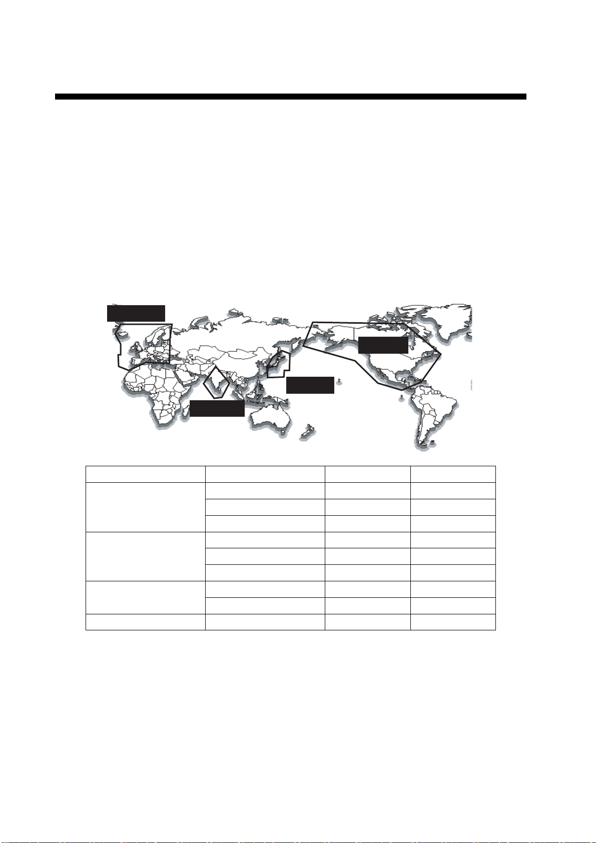
SYSTEM OVERVIEW
The GP-320B is a GPS receiver with WAAS (Wide Area Augmentation System) capability.
WAAS, available in North America, is a provider in the worldwide SBAS (Satellite Based
Augmentation System) navigation system. CBAS provides GPS signal corrections to SBAS
users, for even better position accuracy, typically better than three meters. There are three more
SBAS providers, MSAS (Multi-Functional Satellite Augmentation System) for Japan, EGNOS
(Euro Geostationary Navigation Overlay Service) for Europe and GAGAN (GPS And GEO
Augmented Navigation) for India. The illustration below shows the coverage area. (Accuracy
may be affected when using a GEO satellite not within your current location.) This manual uses
“WAAS” for these three providers generically.
EGNOS
WAAS
MSAS
GAGAN
Provider Satellite type Longitude Satellite No.
Intelsat Galaxy XV 133°W 135
WAAS
EGNOS
MSAS
GAGAN Inmarsat-4-F1 64°E 127
TeleSat Anik F1R 107.3° 138
Inmarsat-4-F3 98°W 133
Inmarsat-3-F2/AOR-E 15.5°W 120
Artemis 21.5°E 124
Inmarsat-4-F2 25°E 126
MTSAT-1R 140°E 129
MTSAT-2 145°E 137
iv
Page 7

NavNet Series
Model 1722C Model 1833C
Model 1722 Model 1933C
Model 1732C Model 1943C
Model 1732 Model 1833
Model 1742C Model 1933
Model 1742 Model 1943
Model 1752C Model 1953C
Model 1752 GD-1900C
Model 1762C GD-1700C
Model 1762 GD-1700
Multi Display RD-30*
Echo Sounder LS-6100
* = WAAS is inoperative.
Other Equipment*
GD-XXXX
GR-80
Ship's Mains (12-24 VDC)
JUNCTION BOX
This GPS receiver complies with Canadian standard RSS-210 (Low Power
License-Exempt Radio communication Devices).
Operation is subject to the following two conditions:
(1) this device may not cause interference, and
(2) this device must accept any interference, including interference that may
cause undesired operation of the device.
v
Page 8

EQUIPMENT LISTS
Standard supply
Name Type Code No. Qty Remarks
GPS Receiver GP-320B ⎯ 1 With 10 m cable
Optional equipment
Name Type Code No. Qty Remarks
Cable Assembly MJ-A7SPF/SRMD-100 000-144-534 1 7P-7P, straight,
10 m
Mast Mounting Kit CP20-01111 004-365-780 1
Right Angle
Antenna Base
L-angle Antenna
Base
Handrail-mount
Antenna Base
NO.13-QA330
NO.13-QA310 000-803-240 1
NO.13-RC5160 000-806-114 1
000-803-239
1
vi
Page 9

1. MOUNTING
NOTICE
Do not apply paint, anti-corrosive
sealant or contact spray to coating or
plastic parts of the equipment.
Those items contain organic solvents that
can damage coating and plastic parts,
especially plastic connectors.
Mounting considerations
Follow the guidelines below to choose a suitable mounting location for the antenna unit.
• The antenna may be mounted three ways: screwed into a pipe (local supply), fixed to a
post with the optional mast mounting kit, or screwed into an optional mounting base. For
fixing by the post or pipe, it is recommended to use stays to prevent damage to the GPS
receiver.
• Select a location out of the radar beam. The radar beam will obstruct or prevent
reception of the GPS signal.
• The location should be well away from a VHF antenna. A GPS receiver is interfered by a
harmonic wave of a VHF antenna.
• The location should be well away from an Inmarsat antenna. Inmarsat transmission will
obstruct or prevent reception of the GPS signal.
• There should be no interfering object within the line-of-sight to the satellites. Objects
within line-of-sight to a satellite, for example, a mast, may block reception or prolong
acquisition time.
• Mount the antenna unit as high as possible to keep it free of interfering objects and
water spray, which can obstruct reception of the GPS signal if the water freezes.
• Observe the following minimum separation distances from other antenna units.
LOOP ANTENNA
WHIP ANTENNA(VHF/UHF) WHIP ANTENNA(MF/HF)
INMARSAT ANTENNA
a
5 m
NOT WITHIN INMARSAT BEAM
NOT WITHIN RADAR BEAM
* = DISTANCE DEPENDS ON MAST DIAMETER OF ’a’.
DIA. OF ’a’ DISTANCE (MIN.)
10 cm
30 cm
1.5 m
3 m
RX WHIP ANTENNA
3 m
*
0.5 m
1 m1 m
GPS ANTENNA
4 m
4 m
MAIN MAST
TX ANTENNA(MF/HF)
1.5 m
Mounting procedure
Install the antenna unit by referring to the installation diagram on page D-1.
1
Page 10

2. WIRING
This unit outputs position and speed to external equipment. NavNet equipment, Multi
Display RD-30 and Echo Sounder LS-6100 can be connected directl y. For connection to
other equipment, use a junction box (local supply) which has seven terminals.
The antenna cable is 10 meters long. If the distance between the antenna unit and the
display monitor is more than 10 meters, use the optional cable assy. (10 m). Up t o f our
extension cables can be connected serially.
Connecting to FURUNO NavNet equipment
Connect the antenna cable to the DATA1 port on NavNet equipment.
Antenna Cable
10 m
Cable assy. (option)
MJ-A7SPF/SRMD-100
10 m (max. 4)
Total length: Max. 50 m
NavNet
DATA 1 port
Waterproofing connectors
If you use the cable assy.(s), waterproof their connectors by wrapping them with vulcanizing
tape and then vinyl tape. Bind tape ends with suitable cable-ties.
2
Page 11

Connecting to Multi Display RD-30
WAAS is not operative in this installation.
Antenna Cable
10 m
12-24 VDC
IN/OUT port
Connecting to Echo Sounder LS-6100
AUX port
MULTI DISPLAY
RD-30
AUX
12-24
VDC
IN/OUT
Rear Panel
Antenna Cable
10 m
12 VDC
ECHO SOUNDER
LS-6100
NMEA
NMEA
XDR
POWER
12VDC
POWER
REAR
3
Page 12

Connecting to other equipment
Remove the connector from the antenna cable and attach crimp-on lugs or similar terminals
to the cable’s cores. Connect the cores to the junction box as below.
Antenna Cable
10 m
*1: RS-422 signal can
be received by using
current loop.
*2: Supply from breaker on switchboard
JUNCTION BOX
YELLOW
GREEN
WHITE
BLUE
RED
BLACK
Drain Wire
non-NavNet equipment
1
2
3
4
5
6
7
RD-A
3
RD-B
4
TD-A
1
TD-B
2
Switchboard breaker
12-24 VDC*
RS-422*1 input for radar/plotter
NMEA 0183 Ver. 2.0
Correction data from GR-80
output in RS-422 format
Fuse 0.5 A
2
(Input current: 105-55 mA)
Note 1: When connecting FURUNO DGPS beacon receiver GR-80 to this unit, set it as
follows:
Byte Format, 8-6; First Bit, LSB; Parity Bit, None; Stop Bit, 1; Bit Rate, 8.
Note 2: The signal ground and frame ground are separated, however the power line is not
isolated. Therefore, do not connect the signal ground to the frame ground when
other equipment is connected to a positive ground battery.
Note 3: WAAS function is inoperative when wiring as shown above.
4
Page 13

Output/Input data sentences
Settable
Priority Input Data Output Data
High
↑
↓
Low
Note 1: Data output from high to low priority.
Note 2: GPDT M data is at tached in f r ont of GPGGA, GPGLL and GPRMC when those
Note 3: “XX” means talker ID.
GPDTM Geometric datum Yes Yes
XXGGA GPS position
status (time of fix,
latitude, longitude,
receive status,
satellite used)
XXZDA UTC date (time in
minutes and
seconds, day,
month, year, time)
XXGLL Position (latitude,
longitude)
GPVTG Course over
XXRMC Navigation data
(UTC time and
latitude, longitude,
ground speed,
true course, year,
month, day)
sentences are output.
GPGGA GPS fix data Yes Yes
GPZDA UTC time and date Yes Yes
GPGLL Geographic
position, latitude
and longitude
ground and ground
speed
GPRMC Recommended
minimum specific
GPS/TRANSIT
data
Output
Cycle
Yes Yes
Yes Yes
Yes Yes
Default
Output
5
Page 14

3. DEFAULT SETTINGS
Setting Default setting Backup
Initial Latitude/Longitude North=34°44.0000, East=135°21.0 000 Yes
Date, Time 2001/1/1, 00:00:13 Yes
G
P
Antenna Height 0 m Yes
S
Almanac Data Yes
Ephemeris Data Yes
Local Zone Time +0 Yes
R
PDOP 6 Yes
E
Geometric Datum WGS84 Yes
C
Mask Elevation 5° Yes
E
Disable Satellite None No
I
Smoothing Coefficient 2 (Standard) No
V
Dynamic Coefficient 2 (Standard) No
E
Data Output (Cycle) DTM, GGA, ZDA, GLL, VTG, RMC (1 s) Yes
R
DGPS Setting Parameter 1 (LSB first) Yes
GEO Satellite, Provider ID Auto: from 120, in sequential order No
W
A
WAAS Availability OFF No
A
Type 0 Message 0: Correct data not output for 60 s Yes
S
6
Page 15

4. TROUBLESHOOTING, BATTERY
Troubleshooting
If the message “No position data” appears on the displa y of NavNet equipment, there may
be a problem with the GPS receiver. Turn off the power and then check the following points:
1) Check for objects around the antenna which may interf ere with recep t ion.
2) Check that the antenna cable is firm ly fast ened.
3) If extension cable(s) are used, check for water leakage at junct ion point(s).
4) Check the antenna cable for damage.
5) Check the antenna for damage.
If the problem seems to be with the antenna ca ble or antenna, contact your dealer.
Battery
The antenna unit contains a lithium battery which preserves data when the power is turned
off, and its life is approximately 20 years (operating rate 70%) for large vessels and 10
years (operating rate 20%) for small vessels. The equipment can be used when the voltage
of the battery is low, however data is not backed up and the unit starts up in the “cold start”
condition.
7
Page 16

SPECIFICATIONS OF THE GPS RECEIVER
GP-320B
1. GENERAL
1.1 Receiving Channels
GPS 12 channels parallel, 12 satellites tracking
WAAS 1 channel
1.2 Rx Frequency 1575.42 MHz
1.3 Rx Code C/A code, WAAS
1.4 Position Fixing System All in view, 8-state Kalman filter
1.5 Position Accuracy
GPS 10 m (95% of the time, HDOP 4)
DGPS 5 m (95% of the time, external data required)
WAAS 3 m (95% of the time)
1.6 Tracking Velocity 999 kt
1.7 Position-fixing Time Warm start: 12 s approx., Cold start: 90 s approx.
1.8 Position Update Interval 1 s
2. I/O INTERFACE
2.1 Data format IEC 61162-1 (NMEA 0183 Ver 2.30)
2.2 Output data DTM, GGA, ZDA, VTG, GLL, RMC
2.3 Input data DGPS: RTCM SC-104
Control command
3. POWER SUPPLY
12-24 VDC: 105-55 mA
4. ENVIRONMENTAL CONDITION
4.1 Ambient Temperature -25°C to +70°C
4.2 Relative Humidity 95% at 40°C
4.3 Water proofing IEC 60529: IPX6
4.4 Vibration IEC 60945
5. COATING COLOR
N9.5
SP - 1 E4422S01A
Page 17

PACKING LIST
A-1
GP-320B(E)
20AW-X-9852 -1
1/1
N A M E
ユニット UNIT
GPS受信機
GPS RECEIVER
図書 DOCUMENT
取扱説明書
OPERATOR'S MANUAL
O U T L I N E
DESCRIPTION/CODE №
GP-320B(E)
004-367-500-00
OME-44220-*
000-809-291-1*
Q'TY
1
1
型式/コード番号が2段の場合、下段より上段に代わる過渡期品であり、どちらかが入っています。 なお、品質は変わりません。
TWO TYPES AND CODES MAY BE LISTED FOR AN ITEM. THE LOWER PRODUCT MAY BE SHIPPED IN PLACE OF THE UPPER
PRODUCT. QUALITY IS THE SAME.
(略図の寸法は、参考値です。 DIMENSIONS IN DRAWING FOR REFERENCE ONLY.)
20AW-X-9852
Page 18

Sep.20 '02
D-1
Page 19

Page 20

9-52 Ashihara-cho,
*
00080929110
**00080929110
*
Nishinomiya, 662-8580, JAPAN
Telephone : +81-(0)798-65-2111
Fax :+81-(0)798-65-4200
The paper used in this manual
is elemental chlorine free.
・FURUNO Authorized Distributor/Dealer
All rights reserved.
Pub. No. OME-44220-B2
(AKMU ) GP-320B
Printed in Japan
A : APR 2002
.
B2 : JAN . 13, 2011
*00080929110**00080929110*
* 0 0 0 8 0 9 2 9 1 1 0 *
 Loading...