

Page 1

GPS NAVIGATOR
DGPS NAVIGATOR
GP-31/GP-36
Page 2

9-52 Ashihara-cho,9-52 Ashihara-cho,
A
A
*00080877701**00080877701*
*00080877701**00080877701*
*OME43990K00**OME43990K00*
Nishinomiya, JapanNishinomiya, Japan
Telephone :Telephone : 0798-65-21110798-65-2111
Telefax :Telefax : 0798-65-42000798-65-4200
Your Local Agent/DealerYour Local Agent/Dealer
ll rights reserved.
ll rights reserved.
PUB.No.PUB.No. OME-43990OME-43990
(( YOSHYOSH ))
GP-31/36GP-31/36
Printed in JapanPrinted in Japan
FIRST EDITION :FIRST EDITION : MAY.MAY. 19991999
K :K : APR.APR. 26,200226,2002
* 0 0 0 8 0 8 7 7 7 0 1 ** 0 0 0 8 0 8 7 7 7 0 1 *
*OME43990K00**OME43990K00*
* O M E 4 3 9 9 0 K 0 0 ** O M E 4 3 9 9 0 K 0 0 *
Page 3

SAFETY INSTRUCTIONS
Safety Instructions for the Operator
WARNING
Do not open the equipment.
Only qualified personnel should work inside
the equipment.
Do not disassemble or modify the
equipment.
Fire, electrical shock or serious injury can
result.
Immediately turn off the power at the
switchboard if the equipment is emitting
smoke or fire.
Continued use of the equipment can cause
fire or electrical shock. Contact a FURUNO
agent for service.
Keep heater away from equipment.
CAUTION
Do not use the equipment for other than
its intended purpose.
Improper use of the equipment can result in
personal injury or equipment damage.
No one navigation device should ever
be solely replied upon for the navigation
of a vessel.
Always confirm position against all available aids to navigation, for safety of vessel
and crew.
GPS position and velocity accuracies
are controlled by the U.S. Department of
Defense. Position may be degraded
up to 100 meters.
A heater can melt the equipment’s power
cord, which can cause fire or electrical
shock.
Use the proper fuse.
A 1A fuse is provided in the power/data
cable. Use only a 1A fuse—use of a wrong
fuse can result in equipment damage.
iiiiiiiiiiiii
i
Page 4
Safety Instructions for the Installer
WARNING
Do not open the cover unless totally
familiar with electrical circuits and
service manual.
Improper handling can result in electrical
shock.
Turn off the power at the switchboard
before beginning the installation.
Fire or electrical shock can result if the
power is left on.
Be sure that the power supply is
compatible with the voltage rating of
the equipment.
Connection of an incorrect power supply
can cause fire or equipment damage. The
voltage rating of the equipment appears
on the label above the power connector.
CAUTION
Ground the equipment to
prevent mutual interference.
Observe the following compass safe
distances to prevent interference to a
magnetic compass:
Standard Steering
compass compass
Display
unit
0.5 m 0.3 m
DO NOT CUT THE ANTENNA CABLE.
See the instructions on the CAUTION
SHEET and the chapter on installation.
ii
iiiiiiiiiiiiiiiiiiiiiiiiii
Page 5

TABLE OF CONTENTS
FOREWORD........................................... iv
SYSTEM CONFIGURATION............... v
EQUIPMENT LISTS.............................. vi
1. OPERATIONAL OVERVIEW
1.1 Control Description .............................1-1
1.2 Turning On and Off the Power ............1-2
1.3 Adjusting Display Dimmer
and Contrast .......................................1-2
1.4 Display Modes ....................................1-3
1.5 Basic Menu Operation ........................1-7
1.6 Simulator Display ................................1-8
2. PLOTTER DISPLAY
OVERVIEW
2.1 Enlarging/Shrinking the
Display Range.....................................2-1
2.2 Shifting the Cursor ..............................2-1
2.3 Shifting the Display .............................2-2
2.4 Centering Own Ship’s Position ........... 2-2
2.5 Changing Track Plotting Interval,
Stopping Plotting of Track...................2-2
2.6 Erasing Track ......................................2-3
3. WAYPOINTS (MARKS)
3.1 Entering Waypoints .............................3-1
3.2 Entering the MOB Mark ......................3-3
3.3 Displaying Waypoint Name.................3-4
3.4 Editing Waypoints on the
WPTS/MRKS List................................3-4
3.5 Deleting Waypoints............................. 3-5
4. ROUTES
4.1 Creating a Route.................................4-1
4.2 Editing Routes.....................................4-4
4.3 Deleting a Route .................................4-6
5. NAVIGATION
5.1 Setting Destination by Cursor .............5-1
5.2 Setting Destination by Waypoint .........5-1
5.3 Setting Route as Destination ..............5-2
5.4 Canceling Destination.........................5-2
6. ALARMS
6.1 Arrival Alarm, Anchor Watch Alarm .....6-1
6.2 XTE (Cross Track Error) Alarm ...........6-2
6.3 Speed Alarm .......................................6-3
6.4 DGPS Alarm........................................6-3
6.5 Time Alarm ..........................................6-3
6.6 Trip Distance Alarm.............................6-4
6.7 Buzzer Type Selection ........................6-4
7. OTHER FUNCTIONS
7.1 Calculating Range, Bearing and TTG.7-1
7.2 DGPS Setup, DGPS Data ..................7-2
7.3 Bearing Reference.............................. 7-5
7.4 Magnetic Variation ..............................7-5
7.5 Geodetic Chart System.......................7-6
7.6 Units of Measurement.........................7-6
7.7 Position Display Format......................7-6
7.8 Time Difference (using local time) ......7-7
7.9 GPS Setup ..........................................7-7
7.10 User Display Setup ...........................7-9
7.11 Resetting Trip Distance...................7-10
7.12 Uploading, Downloading Waypoint,
Route Data......................................7-10
7.13 Time Display ...................................7-14
8. MAINTENANCE &
TROUBLESHOOTING
8.1 Maintenance .......................................8-1
8.2 Displaying the Message Board ...........8-1
8.3 Displaying the GPS
Satellite Monitor Display .....................8-2
8.4 Diagnostic Test....................................8-2
8.5 When “BATTERY ALARM!” Appears ..8-3
8.6 Clearing Data ......................................8-4
9. INSTALLATION
9.1 Installation of Display Unit ..................9-1
9.2 Installation of Antenna Unit.................9-1
9.3 Wiring..................................................9-2
9.4 Initial Settings......................................9-3
APPENDIX
Menu Tree.............................................. AP-1
Loran C Chains ...................................... AP-3
Decca Chains.........................................AP-4
Geodetic Chart List ................................AP-5
SPECIFICATIONS............................ SP-1
OUTLINE DRAWING......................... D-1
INTERCONNECTION DIAGRAM .. S-1
INDEX ..............................................Index-1
Declaration of Conformity (GP-31, GP-36)
iii
Page 6

FOREWORD
A Word to GP-31/GP-36
Owners
Congratulations on your choice of the GP31 GPS Navigator , GP-36 DGPS Navigator.
We are confident you will see why the
FURUNO name has become synonymous
with quality and reliability.
For over 50 years FURUNO Electric Company has enjoyed an enviable reputation for
innovative and dependable marine electronics equipment. This dedication to excellence
is furthered by our extensive global network
of agents and dealers.
Your navigator is designed and constructed
to meet the rigorous demands of the marine
environment. However , no machine can perform its intended function unless installed,
operated and maintained properly. Please
carefully read and follow the recommended
procedures for installation, operation, and
maintenance.
We would appreciate hearing from you, the
end-user , about whether we are achieving our
purposes.
Thank you for considering and purchasing
FURUNO equipment.
Features
The GP-31/GP-36 is a totally integrated GPS
receiver and video plotter, and consists of a
display unit and an antenna unit.
The GP-36 additionally has a DGPS beacon
receiver built in its display unit. The high sensitivity GPS receiver tracks up to twelve satellites simultaneously . An 8-state Kalman filter
ensures optimum accuracy in determination
of vessel position, course and speed.
The main features of the GP-31/GP-36 are
• A DGPS beacon receiver (external) may
be connected to the GP-31 to add DGPS
function.
• Comprehensive navigation data displays
• Storage for 950 waypoints and 50 routes
• Alarms: Arrival, Anchor Watch, XTE
(Cross-track Error), Trip, T ime, DGPS, and
Speed.
• Man overboard feature records latitude
and longitude or TD (Loran C or Decca)
coordinates at time of man overboard and
provides continuous updates of range and
bearing when navigating to the MOB position.
• Menu-driven operation
• Bright 95 x 60 mm LCD with adjustable
contrast and brilliance
• Autopilot (option) may be connected, and
steering data output to the autopilot.
• Unique “Highway” display provides a
graphic presentation of ship’s progress
toward a waypoint.
• Own ship’s position may be shown in latitude and longitude or TD (Loran C or
Decca).
• Waypoint and route data can be uploaded
from a PC or downloaded to a PC.
iv
Page 7
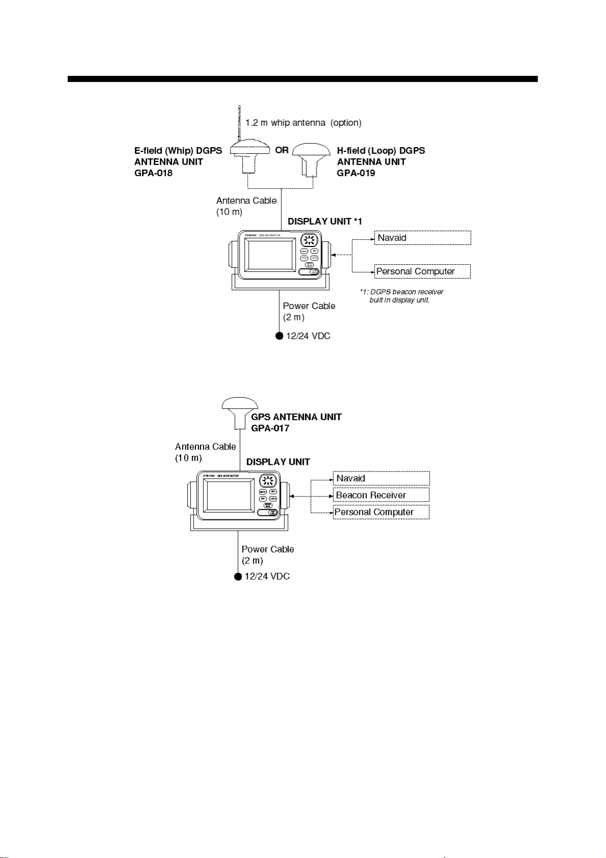
v
SYSTEM CONFIGURATION
GP-36 System configuration
GP-31 System configuration
Page 8

Standard supply
emaNepyTytQskrameR
EQUIPMENT LISTS
tinUyalpsiD63-PG
13-PGdraobNOCAEBoN
tinUannetnA710-APG
810-APG
910-APG
noitallatsnI
slairetaM
straPerapStes1,A1GMGF:epyT,.scp2(esuF
seirosseccAtes1,1901-610-02:epyT(revocdraH
1
1
detaroprocnidraobNOCAEBregnahgnidulcnI
stlobbonkdna
elbacm01htiw,13-PGroF
m01/w,annetnaSPGD)pihw(dleif-E,63-PGroF
elbac
m01/w,annetnaSPGD)pool(dleif-H,63-PGroF
elbac
tes1,020-5000FPS7A-JM:epyT(elbacataD/rewoP•
)483-931-000:.oNedoC
foannetnapihwrof,.cp1(rehsawgnirpS•
)162-468-000:.oNedoC,01M:epyT,810-APG
,tinuyalpsidgnixifrof,.scp4(wercsgnippaT•
180-208-000:.oNedoC,02X5:epyT
)508-411-000:.oNedoC
)230-792-001:.oNedoC
Optional equipment
emaNepyT.oNedoCskrameR
elgnAthgiR
esaBannetnA
annetnAepyt-L
esaB
annetnAliardnaH
esaB
tiKtnuoMtsaM11110-02PC087-563-400
.yssAelbaC020-5000FPS7A-JM483-931-000
StiKtnuoMhsulF71-02-PO027-040-000yalpsidehtgnitnuomhsulfroF
FtiKtnuoMhsulF92-02-PO504-140-000
033AQ-31.oN932-308-000annetnaroF
tinu
013AQ-31.oN042-308-000
0615CR-31.oN411-608-000
tinu
vi
Page 9
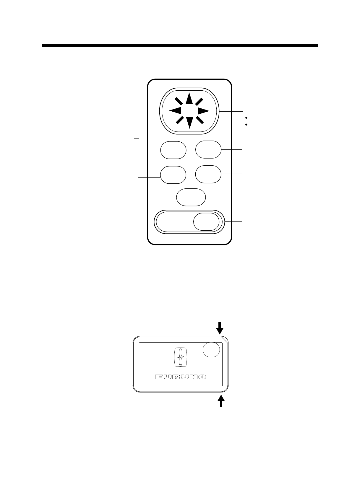
Press once: Zoom, centering,
or escapes from current operation, depending on display in
use.
Press twice: Opens menu.
Selects display mode.
Long press: Turns power
off.
Touch and release: Turns
power on. Opens the display
for adjustment of dimmer
and contrast.
Inscribes mark, MOB mark
on the display.
Sets/cancels destination.
Registers items on menus.
Cursor Pad
Shifts cursor and display.
Selects items on menus.
MENU
DIM
PWR
MARK
MOB
ENT
DISP
GOTO
1. OPERATIONAL OVER VIEW
1.1 Control Description
Removing the hard cover
To remove the hard cover, squeeze it at its top and bottom right (or left) corners and pull it
toward you.
Figure 1-1 Control panel
Pressure
Pressure
1-1
Page 10
1.2 Turning On and Off the
Turning off the power
Power
Turning on the power
Press the [DIM/PWR] key. The unit beeps
and then starts up with the last-used display mode.
Your equipment takes about two minutes
to find its position when turned on for the
very first time.
The equipment shows receiver status indications at the top left-hand corner in all display modes. Table 1-1 shows these
indications and their meanings.
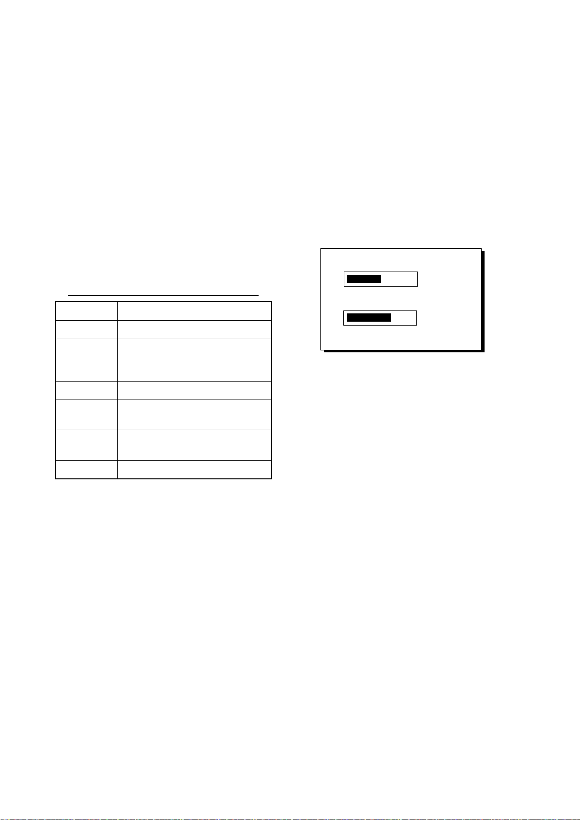
Table 1-1 Receiver status indications
noitacidnIgninaeM
D2xifnoitisopSPGD2lamroN
PODhtiwxifnoitisopSPG
POD
D3xifnoitisopSPGD3lamroN
D2D
D3D
MIS.edomnoitalumiS
:POD rofxedniehT.noisicerPfonoituliD
.xifnoitisop
:etoN nosdnepedoslaycaruccanoitisoP
)xifnoitisopD3(6
SPGlaitnereffidlamroN
xifnoitisop
xifnoitisop
ehtfoycaruccaehtrehgihehtrebmun
.noitisopetilletas
ro)xifnoitisopD2(4nahterom
SPGlaitnereffidD3lamroN
ehtrehgihehT.ycaruccagnixif-noitisop
Press and hold down the [DIM/PWR] key
until the screen goes blank, approx. three
seconds. The time remaining until power
off is counted down on the display.
1.3 Adjusting Display Dimmer and Contrast
1. Press the [DIM/PWR] key with a touchand-release action. The display shown
in Figure 1-2 appears.
DIMMER (1~8)
▼
CONTRAST (0~63)
t
Figure 1-2 Screen for adjustment of
display dimmer and contrast
2. T o adjust the dimmer , press ▲ or ▼. Current setting is shown to the right of “▲”.
3. To adjust the contrast, press t or s.
Current setting is shown to the right of
“s”.
4. Press the [ENT] key to finish.
Note: If you turn off the power with
minimum contrast,nothing appears on the
display when you turn on the power
again.Adjust the contrast as described
above.
▲
4
41
s
EXIT:[ENT]
1-2
Page 11
1-3
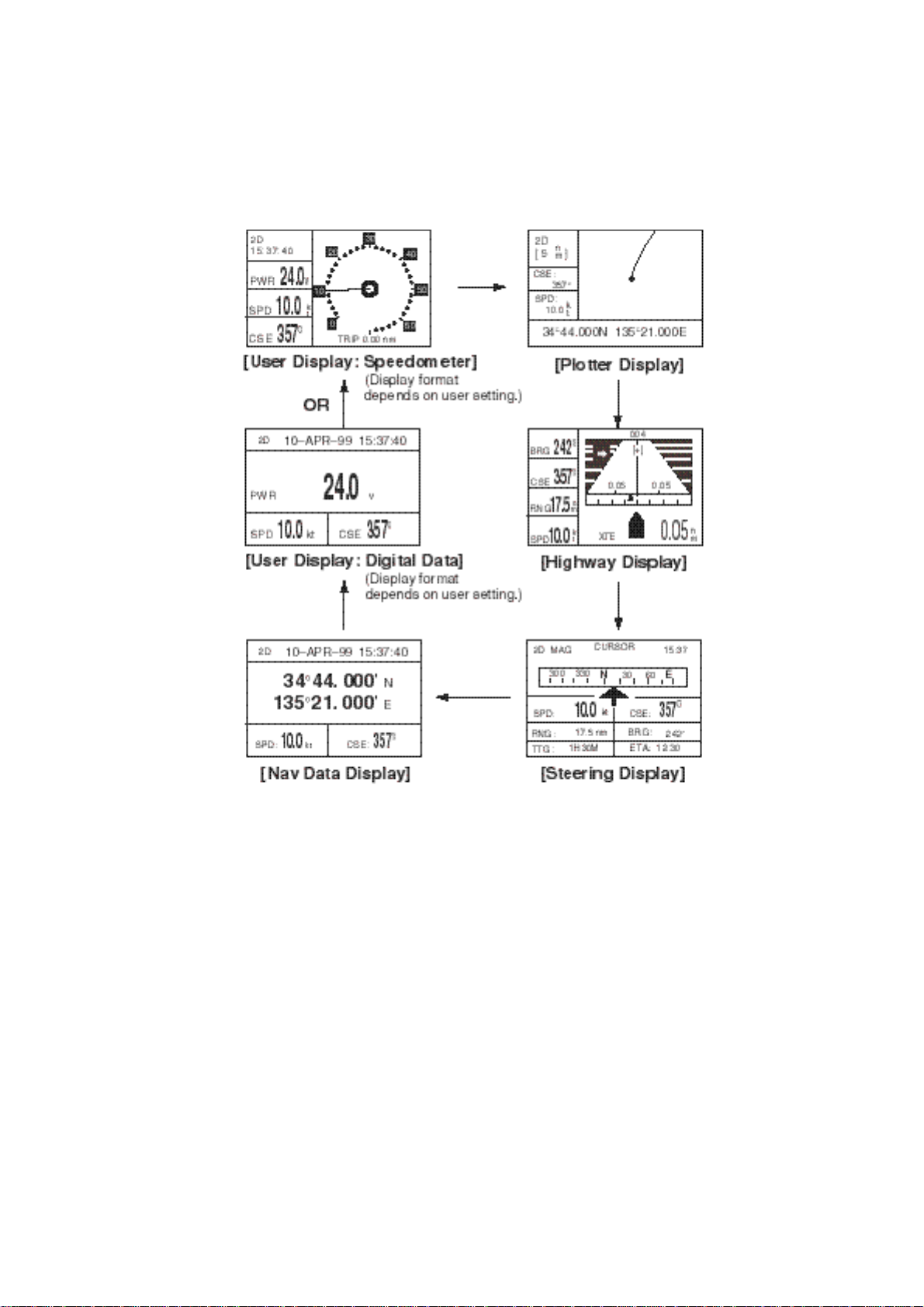
1.4 Display Modes
Your unit has five display modes: Plotter Display, Highway Display, Steering Display, Nav
Data Display and User Display (digital data or speedometer). Press the [DISP] key to
select a display mode. Each time the key is pressed, the display mode changes in the
sequence shown below.
Figure 1-3 Display modes
Note: Position data can be shown in latitude and longitude or TDs (Loran C or Decca).
Page 12
1-4
Plotter display
The plotter display traces own ship’s track, and shows position, course, speed, and horizontal display range setting.
Figure 1-4 Plotter display
Highway display
The highway display provides a 3-D view of own ship’s progress toward destination. Nav
data is also shown.
Figure 1-5 Highway display
Page 13
1-5
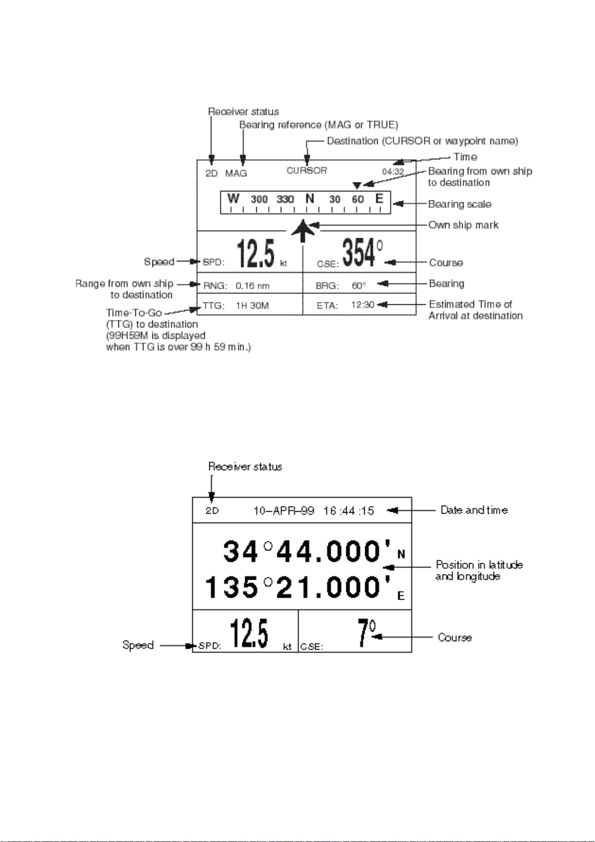
Steering display
The steering display provides steering information such as ship’s speed, course; range,
bearing, ETA and TTG (Time-To-Go) to destination.
Figure 1-6 Steering display
Nav data display
The nav data display shows position in latitude and longitude (or TDs), course, speed,
date and time.
Figure 1-7 Nav data display
Page 14

1-6
User displays
Two user displays are available, digital and speedometer, and the operator may select
which to display. The default display is the digital display.
Digital display
The digital display shows digital navigation data. The user may choose what data to display in the three cells below the receiver status, date and time indications. The choices of
data are speed, course, range, bearing, time-to-go, estimated time of arrival, trip distance
and power source voltage.
Figure 1-8 Digital display
Speedometer display
The speedometer display provides both digital and analog speed readouts. Additionally it
provides three cells of data (below the receiver status and time indication) which the user
may choose. The choices are the same as those for the digital display.
Figure 1-9 Speedometer display
Page 15
1-7
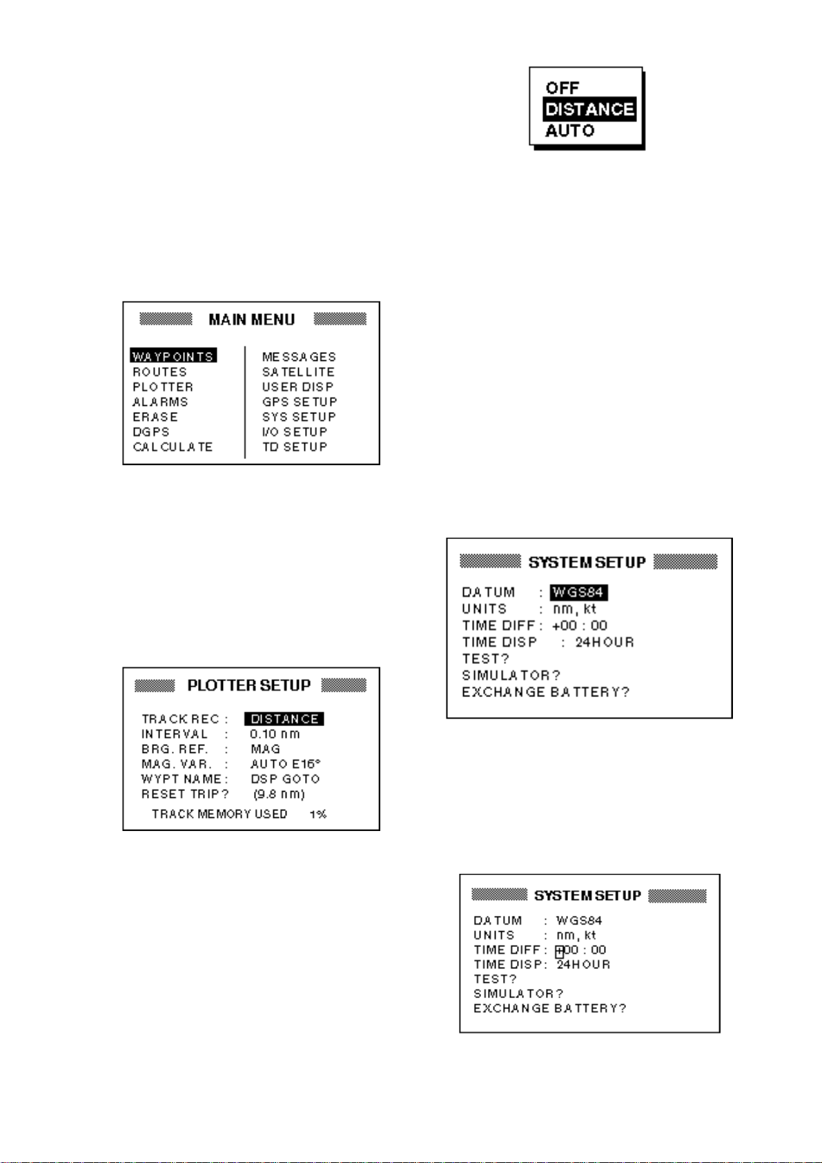
1.5 Basic Menu Operation
Most operations of the your unit are carried out through the menu. Below is a quick
introduction to how to select a menu and
change menu settings. If you get lost in operation, press the [MENU] key to return to
the MAIN menu. A complete menu tree
appears in the Appendix.
1. Press the [MENU] key once or twice to
display the menu.
Figure 1-12 Options of TRACK REC
5. Press ▲ or ▼ to select option desired.
6. Press the [ENT] key.
7. Press the [MENU] key twice to finish.
Figure 1-10 Menu
Once: At the steering display, nav
data display, user display.
Twice: At the plotter display, highway
display.
2. Operate the cursor pad to select a menu
and press the [ENT] key. For example,
select PLOTTER and press the [ENT]
key.
How to enter alphanumeric data
In some instances it is necessary to enter
alphanumeric or character data. The example below shows how to enter a time difference of –6:30, to use local time instead
of UTC time.
1. Press the [MENU] key once or twice to
display the menu.
2. Select SYS SETUP and press the [ENT]
key.
Figure 1-11 PLOTTER SETUP menu
3. Press ▲ or ▼ to select menu item. For
example, select the TRACK REC field.
4. Press the [ENT] key. A window showing
options appears. (The figure below
shows the options available for TRACK
REC.)
Figure 1-13 SYS SETUP menu
3. Press ▼ to select the TIME DIFF field.
4. Press the [ENT] key. A cursor circumscribes “+”. This cursor appears whenever selected data can be changed with
the cursor pad.
Figure 1-14 SYSTEM SETUP menu,
TIME DIFF field selected
Page 16
1-8
5. Press ▲ to display “–”.
6. Press to send the cursor to the next
digit.
7. Press ▲ or ▼ to display 0.
8. Press to send the cursor to the next
digit.
9. Press ▲ or ▼ to display 6.
10.Press to send the cursor to the next
digit.
11.Press ▲ or ▼ to display 3.
12.Press to send the cursor to the last
digit.
13.Press ▲ or ▼ to display 0.
14.Press the [ENT] key.
15.Press the [MENU] key twice to finish.
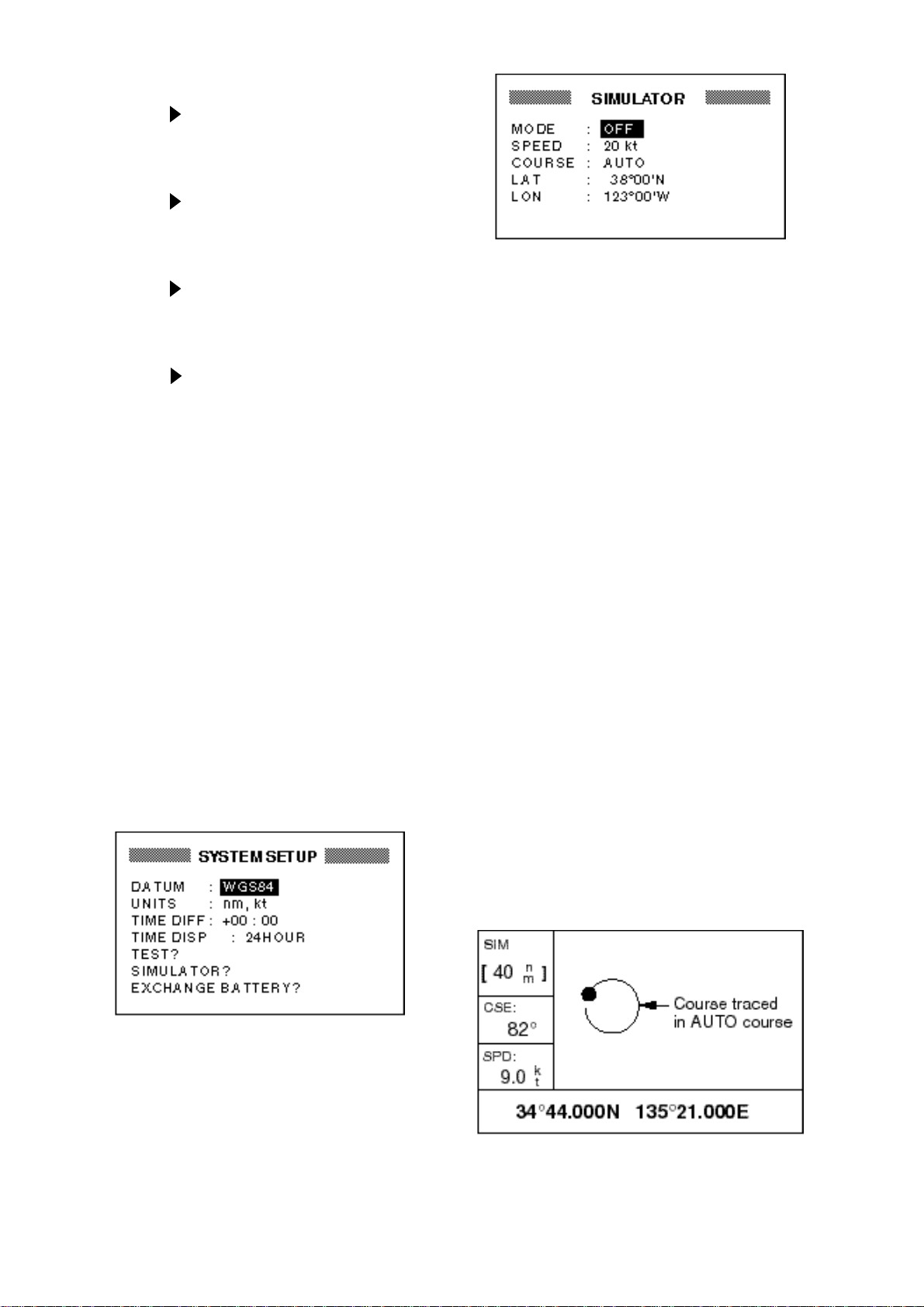
1.6 Simulator Display
The simulator display provides simulated
operation of this unit. You may set the speed
manually and the course manually or automatically. All controls are operative – you
may enter marks, set destination, etc.
1. Press the [MENU] key twice to display
the menu.
2. Select SYS SETUP and press the [ENT]
key.
Figure 1-16 SIMULATOR menu
4. Press the [ENT] key. A window appears
which shows the choices ON or OFF.
5. Select ON and press the [ENT] key.
6. Press the [ENT] key, enter speed to use
for the simulation with the cursor pad,
and press the [ENT] key.
7. Press the [ENT] key.
8. Select course entry method (AUTO or
MANU) and press the [ENT] key. For
manual entry of course, press the [ENT]
key again, enter course with the cursor
pad, and press the [ENT] key again.
(The AUTO course tracks a circular
course.)
9. Press the [ENT] key, enter latitude (usually current latitude) with the cursor pad,
and press the [ENT] key.
10.Press the [ENT] key, enter longitude
(usually current longitude), and press
the [ENT] key.
11.Press the [MENU] key twice.
12.Select the PLOTTER display with the
[DISP] key. SIM appears at the upper
left-hand corner when the simulator display is active.
Figure 1-15 SYSTEM SETUP menu
3. Select “SIMULATOR?” and press the
[ENT] key.
Figure 1-17 Simulator display,
auto course selected
Page 17

1-9
13.To turn off the simulator display, select
OFF at step 5 in this procedure, press
the [ENT] key, and press the [MENU]
key twice to finish.
Note: If the power is reset while the simulator display is in use, the indication SIMULATION MODE appears at the top of the
screen at the next power up, in addition to
the indication SIM. SIMULATION MODE
disappears when any key is pressed.
Page 18

This page is intentionally left blank .
Page 19
2-1
2. PLOTTER DISPLAY OVERVIEW
2.1 Enlarging/Shrinking the
Display Range
You may increase or decrease the display
range on the plotter and highway displays.
The horizontal range in the plotter display
is available among .02 (40 yd), .05 (101 yd),
0.1 (202 yd), 0.2 (405 yd), 0.5, 1, 2, 5, 10,
20, 40, 80, 160 and 320 nautical miles.
(Nautical mile is the default unit of display
range. Display range may also be shown
in kilometers or miles. Ranges shorter than
the value 0.5 are also shown in yards or
meters.) The horizontal range in the highway display is available among 0.2, 0.4, 0.8,
1, 2, 4, 8 and 16 nautical miles.
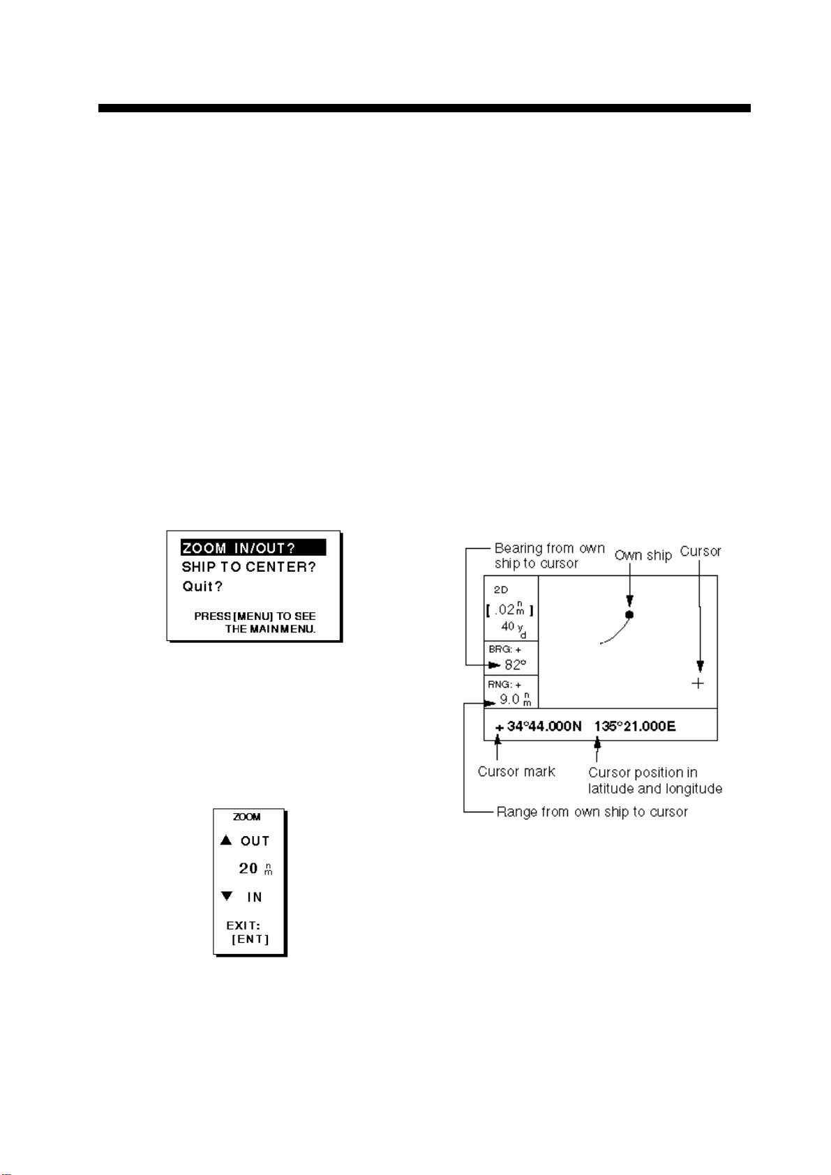
1. Press the [MENU] key. The zoom, ship
centering window appears.
2.2 Shifting the Cursor
Use the cursor pad to shift the cursor. The
cursor moves in the direction of the arrow
or diagonal pressed on the cursor pad.
Cursor state and data
Cursor state determines what data is shown
on the display.
Cursor turned on
Cursor position is displayed in latitude and
longitude or TDs (depending on menu setting) at the bottom of the plotter display
when the cursor is on. The range and bearing from own ship to the cursor appear at
the left-hand side of the display.
Figure 2-1 Zoom, ship centering window
Note: The prompt “SHIP TO CENTER?”
does not appear when the highway
display mode is active.
2. Press the [ENT] key. The zoom window
appears.
Figure 2-2 Zoom window
3. Press ▲ (increase) or ▼ (decrease) to
select range desired.
4. Press the [ENT] key to finish.
Figure 2-3 Data displayed on the plotter
display when the cursor in on
Cursor turned off
The cursor is erased when there is no cursor pad operation for about six seconds.
Ship’s position, speed and course appear
at the left side of the plotter display when
the cursor is off.
Page 20
2-2
Figure 2-4 Data displayed on the plotter
display when the cursor is turned off
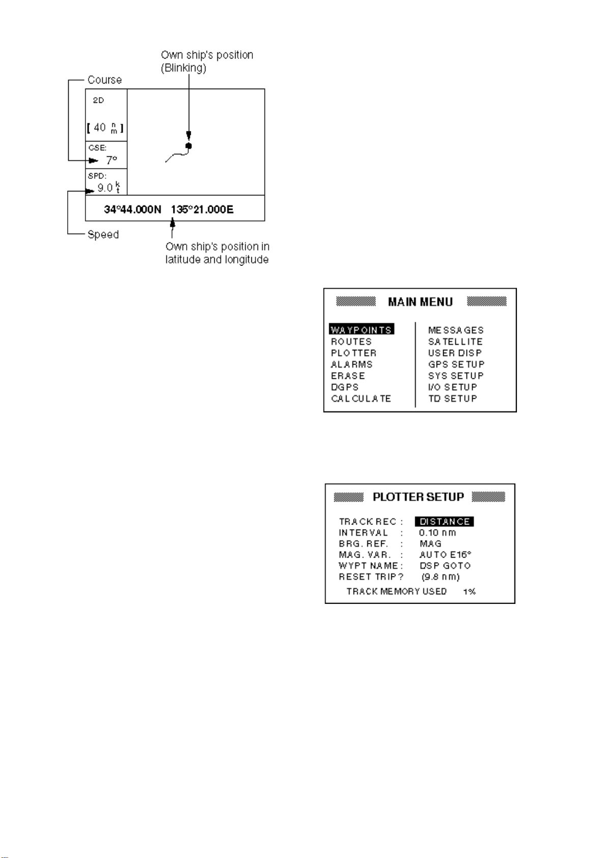
2.3 Shifting the Display
2.5 Changing Track Plotting Interval, Stopping Plotting of Track
To trace the ship’s track, the ship’s position
is stored into the memory at an interval of
distance or automatic recording (memory
capacity: 1,000 points). For distance, a
shorter interval provides better reconstruction of the track, but the storage time of the
track is reduced. When the track memory
becomes full, the oldest track is erased to
make room for the latest.
1. Press the [MENU] key once or twice to
display the menu.
The display can be shifted on the plotter
display. Operate the cursor pad to place the
cursor at an edge of the screen. The display shifts in the direction opposite to cursor pad operation.
2.4 Centering Own Ship’s Position
When own ship tracks off the display the
own ship mark is automatically returned to
the screen center. You can also return it
manually as follows:
1. Press the [MENU] key.
2. Select SHIP TO CENTER?.
3. Press the [ENT] key.
Figure 2-5 Menu
2. Select PLOTTER.
3. Press the [ENT] key.
Figure 2-6 PLOTTER SETUP menu
4. The cursor should be on the TRACK
REC field. Press the [ENT] key. The
track recording method selection window appears.
Page 21
2-3
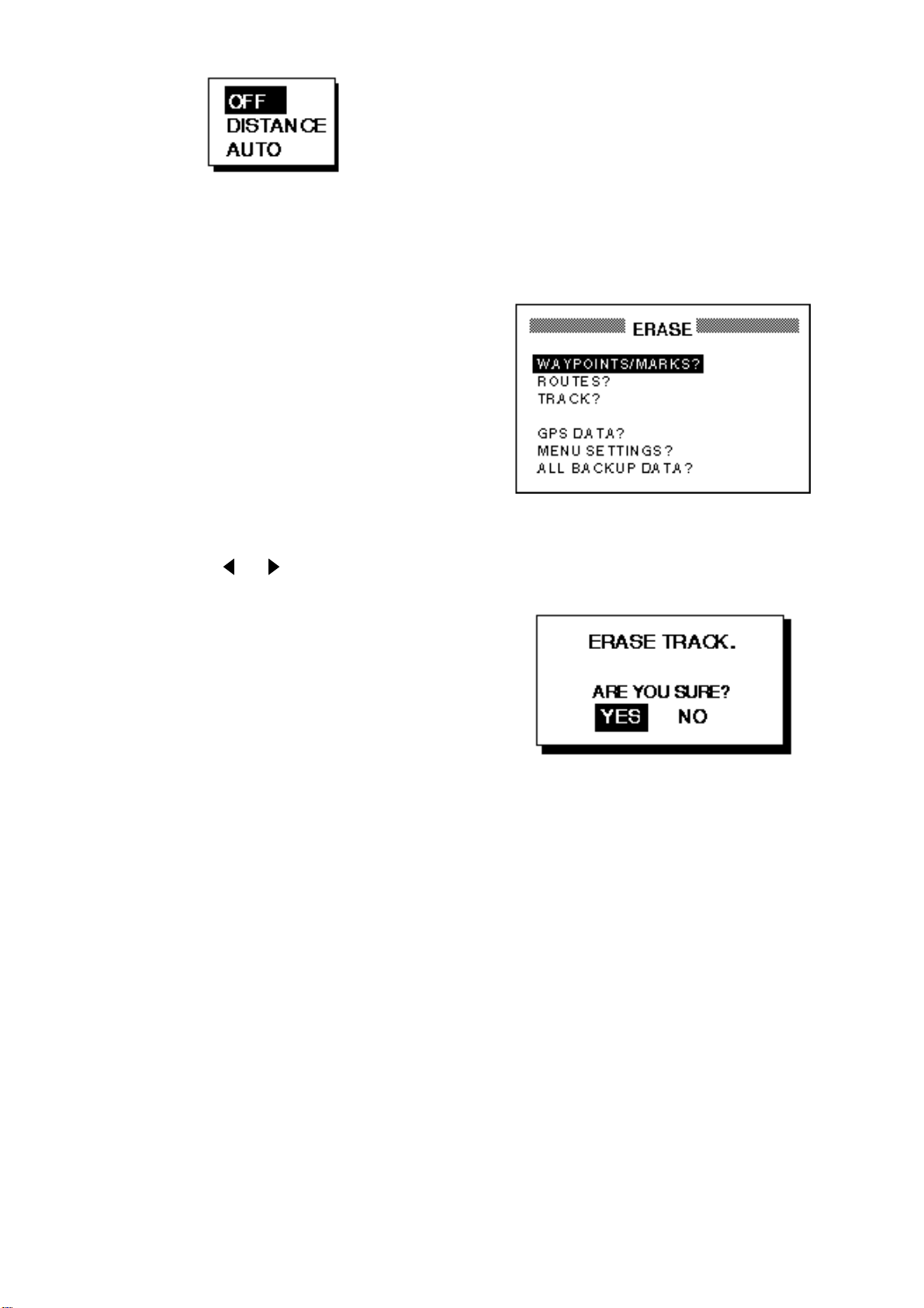
2.6 Erasing Track
All track can be erased. Track cannot be
restored once erased, therefore be absolutely sure you want to erase all track.
Figure 2-7 Track recording
method selection window
5. Select OFF, DISTANCE or AUTO and
then press the [ENT] key.
OFF: Track is neither recorded or plotted. This setting is useful when you do
not need to record track, for example,
when returning to port.
DISTANCE: Track is recorded and plotted at the distance interval set.
AUTO: Plotting and recording interval
changes with chart scale selected.
If you selected DISTANCE, enter the recording interval as follows:
a) Press the [ENT] key.
b) Press or to select digit to
change.
c) Press ▲ or ▼ to change value.
d) Press the [ENT] key after setting.
1. Press the [MENU] key once or twice to
display the menu.
2. Select ERASE and press the [ENT] key
to display the ERASE menu.
Figure 2-8 ERASE menu
3. Select “TRACK?” and press the [ENT]
key. The message shown in Figure 2-9
appears.
6. Press the [MENU] key twice to finish.
Figure 2-9 Prompt for erasure of track
4. Press the [ENT] key to erase all track.
5. Press the [MENU] key twice to finish.
Page 22

This page is intentionally left blank .
Page 23
3-1
3. WAYPOINTS (MARKS)
3.1 Entering Waypoints
In navigation terminology a waypoint is a
particular location on a voyage whether it
be a starting, intermediate or destination
waypoint. Your unit can store 950
waypoints. Waypoints can be entered on
the plotter display four ways: at cursor position, at own ship’s position, through the
menu (manual input of L/L or TD), and by
MOB position.
Entering a waypoint by the cursor
1. On the plotter display, use the cursor
pad to place the cursor on the location
you want to make a waypoint.
2. Press the [ENT] key. The following window appears.
c) Press to move the cursor to the
next column and press ▲ or ▼ to dis-
play B.
d) Press to move the cursor to the
next column and press ▲ or ▼ to dis-
play E.
e) Press the [ENT] key. The following
window appears.
Figure 3-2 Waypoint position,
comment entry window
Figure 3-1 Waypoint name entry window
3. The cursor is on the second line of the
display. This is where you may enter
waypoint name, which may consist of
six characters. (The number shown is
the youngest empty waypoint number.
If you would rather have the unit register the waypoint under that number, and
you do not need to change mark shape
or enter a comment, press the [ENT] key
twice to register the waypoint and finish.) To enter KOBE as the waypoint
name, for example, do the following:
4. This window is where you can select
mark shape, enter a comment, and log
the waypoint to a route. (If you do not
need to change mark shape, enter a
comment, or save waypoint to a route,
select “Exit?” and press the [ENT] key
to finish.) How to log waypoints to a
route will be discussed in the chapter
on routes.
a) Use the cursor pad to place the cur-
sor under MARK.
b) Press the [ENT] key.
c) Select mark desired with ▲ or ▼.
Figure 3-3 Mark selection sequence
a) Press ▲ or ▼ to display K.
b) Press to move the cursor to the
next column and press ▲ or ▼ to dis-
play O.
d) Press the [ENT] key.
Page 24
3-2
e) The cursor is on the date/time field.
Press the [ENT] key.
f) Enter a comment (max. 16 charac-
ters) with the cursor pad (the same
as you did when entering waypoint
name) and press the [ENT] key. To
create a space, select “blank” character. To remove all characters which
follow the cursor, select the underline.
g) The cursor is on “Exit?.” Press the
[ENT] key.
h) Press the [ENT] key again to finish.
Note: “LOG RT?” function is explained in
the chapter on routes.
Entering a waypoint at own ship’s
position
1. Press the [MARK/MOB] key on any display. The following window appears.
5. The cursor is on the date/time field. To
change the date to a comment, press
the [ENT] key, enter a comment with the
cursor pad, and press the [ENT] key
again.
6. Place the cursor on “Exit?.” Press the
[ENT] key to finish.
Entering a waypoint through the
waypoint list
1. Press the [MENU] key once or twice to
display the menu.
2. Select WAYPOINTS.
3. Press the [ENT] key. The following window appears. Select LIST. (NEAREST
displays waypoints from nearest to furthest; however, waypoints cannot be
entered from this display.)
Figure 3-4 Own ship’s position window
2. If you want to register the waypoint under the number shown, and you do not
need to change mark shape, enter a
comment, or log the waypoint to a route,
press the [ENT] key to finish.
3. To change name, select the NAME field,
press the [ENT] key, select name with
the cursor pad, and press the [ENT] key.
4. To change mark shape, place the cursor under MARK. Press the [ENT] key,
select mark shape with the cursor pad,
and press the [ENT] key again.
Figure 3-5 Waypoint list selection window
4. Press the [ENT] key. The WPTS/MRKS
list appears.
Figure 3-6 WPTS/MRKS list
CURSOR: Cursor position when
destination is set with cursor.
MOB: Man overboard position.
START: Starting point when destination is selected.
5. The cursor is on NEW. Press the [ENT]
key.
Page 25
3-3
Figure 3-7 Screen for entering
waypoint name
6. Enter name (if desired) with the cursor
pad and press the [ENT] key.
3.2 Entering the MOB Mark
The MOB mark denotes man overboard position. Only one MOB mark may be entered.
Each time the MOB mark is entered the previous MOB mark and its position data are
written over.
1. Press the [MARK/MOB] key.
Figure 3-9 MOB window
2. Press to select “MOB?.”
Figure 3-8 Screen for entering
waypoint latitude and longitude
7. Use the cursor pad to place the cursor
on the second line (latitude or TD) and
press the [ENT] key. Enter latitude (TD)
and press the [ENT] key.
8. Press the [ENT] key, enter longitude
(TD) in similar fashion as you did with
latitude and press the [ENT] key.
Note: To enter position by TDs, see
paragraph 7.7 “Displaying Position in
TDs.”
9. To change mark shape, select mark
shape currently shown and press the
[ENT] key. Select mark desired with the
cursor pad and press the [ENT] key.
10.To change date and time to the comment of your choice, press the [ENT]
key, enter comment, and press the
[ENT] key again.
Note: Pressing the [ENT] key instead
of at step 2 saves the position as a
waypoint. “LOG RT?” function is
explained in the chapter on routes.
3. Press the [ENT] key.
Figure 3-10 MOB window-2
4. To set MOB position as destination,
press the [ENT] key. Then, the plotter
display marks MOB position as shown
in Figure 3-11.
Note: Selecting “NO” and pressing the
[ENT] key at step 4 saves the position
as a waypoint.
11.Place the cursor on “Exit?.” Press the
[ENT] key.
12.Press the [MENU] key twice to finish.
Page 26

3-4
Figure 3-11 Screen appearance when
MOB is set as destination
3.3 Displaying Waypoint Name
You may display on the plotter display all
waypoint names or only the GOTO
waypoint name as follows:
1. Press the [MENU] key once or twice to
display the menu.
2. Select PLOTTER and press the [ENT]
key.
3. Place the cursor on the WYPT NAME
field and press the [ENT] key. The following window appears.
3.4 Editing Waypoints on the WPTS/MRKS List
Waypoint position, waypoint name, mark
shape and comment can be edited on the
WPTS/MRKS List.
1. Press the [MENU] key once or twice to
display the menu.
2. Select WAYPOINTS and press the
[ENT] key.
3. Select LIST or NEAREST and press the
[ENT] key.
4. Select waypoint to edit and press the
[ENT] key.
Note: CURSOR, MOB or START are
automatically updated according to
destination setting or MOB
setting.Therefore,editing these items
has no meaning.
5. Select the NAME field and press the
[ENT] key.
6. Change name with the cursor pad and
press the [ENT] key. You are then asked
if you want to create or rename the
waypoint, or quit (escape) this display.
Figure 3-12 DSP GOTO, DSP ALL
selection window
4. Select DSP GOTO or DSP ALL as appropriate and press the [ENT] key.
5. Press the [MENU] key twice to finish.
Figure 3-13 CREATE, RENAME prompt
7. Select objective and press the [ENT]
key.
8. Change position, mark shape, comment
as desired.
9. Select “Exit?” and press the [ENT] key.
10.Press the [MENU] key twice to finish.
Page 27

3-5
3.5 Deleting Waypoints
1. Press the [MENU] key once or twice to
display the menu.
2. Select ERASE and press the [ENT] key.
4. Select the waypoint you want to erase.
Note: You cannot erase CURSOR,
MOB or START.
Figure 3-14 ERASE menu
3. The cursor is on the “WAYPOINTS/
MARKS?” field. Press the [ENT] key.
5. Press the [ENT] key. A screen showing
position and other particulars of the
waypoint selected appears.
Figure 3-16 ERASE prompt
6. Select “ERASE?” and press the [ENT]
key.
7. Press the [MENU] key twice to finish.
Figure 3-15 ERASE WP/MRK display
Page 28

This page is intentionally left blank .
Page 29

4-1
In many cases a trip from one place to another involves several course changes, requiring a series of waypoints which you
navigate to, one after another. The sequence of waypoints leading to the ultimate
destination is called a route. Your unit can
automatically advance to the next waypoint
on a route, so you do not have to change
the destination waypoint repeatedly.
4.1 Creating a Route
You can store up to 50 routes (numbered
01 to 50) and one LOG route, and each
route may contain up to 30 waypoints. A
route may be constructed four ways: by the
cursor, through the waypoints list, current
position (track-based route) and through the
route menu.
Note: Be sure to record all important routes
in a separate log. This unit is not a fail-safe
record keeping device.
4. ROUTES
Figure 4-2 Waypoint name entry window
The cursor is on the second line of the
display. This is where you may enter
waypoint name. The number shown is
the youngest empty waypoint number.
If you would rather have the unit
register the waypoint under that number, and you do not need to change
mark shape or enter a comment,
press the [ENT] key to register the
waypoint and proceed to step 5.
3. If desired, change the waypoint
name.(See page 3-1 for how to enter
waypoint name.) Press the [ENT] key.
Figure 4-1 Sample route
Creating a route with cursor
positions
This is probably the easiest method by
which to create a route.
1. Use the cursor pad to place the cursor
on position desired. (Cursor position is
shown at the bottom of the screen.)
2. Press the [ENT] key. The following window appears.
Figure 4-3 Waypoint position,
comment entry window
4. If necessary, change waypoint, position,
mark shape, and comment (date and
time).
5. Select the item “LOG RT?” and press
the [ENT] key.
6. Repeat steps 1 through 5 to complete
the route.
7. When you have entered all the waypoint
positions desired, press the [MENU] key
twice, select ROUTES and press the
[ENT] key.
Page 30

4-2
Figure 4-4 ROUTES menu
8. The LOG field shows the first and last
waypoints entered for the log route you
are currently creating. Select the LOG
field and press the [ENT] key. The EDIT/
MOVE window appears.
Figure 4-5 EDIT/MOVE window
9. Select “MOVE?” and press the [ENT]
key. The route is moved from the LOG
field and is registered under the next sequential route number.
4. Select “NEW?” and press the [ENT] key.
The screen shown in Figure 4-7 appears.
Figure 4-7 Screen for entering route
5. Press ▲ and the [ENT] key to change
route name, if desired. (If no name is
entered the name of the first and last
waypoints in the route will become the
route name, although you may change
the name at a later time.) Enter route
name and press the [ENT] key.The cursor is on line 01 and press the [ENT]
key.
6. Press [ENT] key and press ▲ or ▼ to
display waypoint name. (In the example,
KOBE.)
Creating a route with preregistered
waypoints from the route menu
The procedure which follows describes how
to create a route from two preregistered
waypoints, KOBE and OSAKA, on the
ROUTE screen.
1. Press the [MENU] key once or twice to
display the menu.
2. Select ROUTES.
3. Press the [ENT] key. The screen shown
in Figure 4-6 appears.
Figure 4-6 ROUTES list
7. Press the [ENT] key. The cursor moves
to the next line.
8. Repeat steps 6 and 7 until you have entered all waypoints desired.
Note: If you enter a waypoint which has
not been registered, the display will look
something like the one below. Select
YES to create a new waypoint; NO to
return to the route entry screen.
Figure 4-8 New waypoint name screen
When you select YES followed by [ENT]
key,following screen appears.Edit the
waypoint,select Exit and press the
[ENT] key.
Page 31

4-3
Figure 4-9Waypoint data screen
9. Select “Exit?.”
10.Press the [ENT] key to register the route.
Then, ROUTES list shows the name of
the first and last waypoints, next to route
number.
4. Select a waypoint and press the [ENT]
key. Your screen should look something
like the one in Figure 4-11.
Figure 4-12 Waypoint data screen
5. Select “LOG RT?” and press the [ENT]
key.
6. Repeat steps 4 and 5 to complete the
route.
7. Press the [MENU] key once.
8. Select ROUTES and press the [ENT]
key. Your screen should now look something like the one shown in Figure 4-12.
Figure 4-10 ROUTES list
11.Press the [MENU] key twice to finish.
Creating a route with preregistered
waypoints from the waypoint list
1. Press the [MENU] key once or twice to
display the menu.
2. Select WAYPOINTS and press the
[ENT] key.
3. Select LIST or NEAREST and press the
[ENT] key.
Figure 4-13 ROUTES list
9. Select the LOG field and press the [ENT]
key. The EDIT/MOVE window appears.
Figure 4-14 EDIT/MOVE window
10.Select “MOVE?” and press the [ENT]
key. The route is moved from the LOG
field and assigned the next sequential
route number.
Figure 4-11 Waypoints/marks (list)
Page 32

4-4
Creating a track-based route
This method stores current position at appropriate intervals. It is useful for retracing
previous ship’s track.
1. Press the [MARK/MOB] key.
Note: You can create a route using a combination of current positions and waypoint
positions (including cursor position). The
route can be started from a waypoint position or current position. The former method
allows you to select the route name beforehand.
4.2 Editing Routes
Replacing waypoints in a route
1. Press the [MENU] key once or twice to
display the menu.
Figure 4-15 MOB window
2. Change name, comment, mark shape
if desired. Select “LOG RT?” and press
the [ENT] key.
3. Repeat steps 1 and 2 at appropriate intervals.
4. When you have entered all the waypoint
positions desired, press the [MENU] key
twice, select ROUTES and press the
[ENT] key.
Figure 4-16 ROUTES menu
2. Select ROUTES and press the [ENT]
key.
3. Select the route to edit.
4. Press the [ENT] key.
5. Place the cursor on the waypoint to replace.
6. Press the [ENT] key. The following window appears.
Figure 4-18 Route editing method
selection window
7. “CHANGE?” is selected; press the
[ENT] key.
5. Select the LOG field and press the [ENT]
key. The EDIT/MOVE window appears.
Figure 4-17 EDIT/MOVE window
6. Select “MOVE?” and press the [ENT]
key. The route is moved from the LOG
field and is registered under the next sequential route number.
Figure 4-19 Waypoint screen
8. Press the [ENT] key. Use the cursor pad
to select waypoint.
9. Press the [ENT] key.
Page 33

4-5
Note: If the name selected at step 8
has not been used, the window shown
in Figure 4-19 appears. Select
“CREATE?” or “RENAME?” as
appropriate and press the [ENT] key.
Figure 4-20 CREATE, RENAME prompt
10.Select “Exit?.”
11.Press the [ENT] key.
12.Press the [MENU] key twice to finish.
5. Select the waypoint which will come after the waypoint to be inserted. In Figure 4-20, for example, if you want to
insert a waypoint between KOBE and
001, select 001.
Figure 4-21 ROUTE screen
6. Press the [ENT] key.
7. Select “INSERT?.”
Permanently deleting a waypoint
from a route
1. Press the [MENU] key or twice to display the menu.
2. Select ROUTES and press the [ENT]
key.
3. Select the route from the ROUTES list.
4. Press the [ENT] key.
5. Select the waypoint you want to delete.
6. Press the [ENT] key.
7. Select “REMOVE?.”
8. Press the [ENT] key.
9. Press the [MENU] key twice to finish.
Inserting a waypoint in a route
8. Press the [ENT] key.
9. Use the cursor pad to select waypoint.
10.Press the [ENT] key.
11.Press the [MENU] key twice to finish.
Temporarily deselecting a waypoint
in a route
You can temporarily deselect an unnecessary waypoint from a route. Using the route
created in Figure 4-21 as an example, deselect the 2nd intermediate waypoint.
To insert a waypoint in a route, do the following:
1. Press the [MENU] key once or twice to
display the menu.
2. Select ROUTES and press the [ENT]
key.
3. Select the route from the ROUTES list.
4. Press the [ENT] key.
Figure 4-22 Sample route
If you reconstruct the route without the 2nd
intermediate point it would look like Figure
4-22.
Figure 4-23 Route in Figure 4-21
reconstructed without 2nd
intermediate waypoint
Page 34

4-6
1. Press the [MENU] key once or twice to
display the menu.
2. Select ROUTES and press the [ENT]
key.
3. Select a route from the ROUTES list,
and press the [ENT] key.
4. Place the cursor on the waypoint to skip.
5. Press the [ENT] key.
6. Select “SKIP?” and press the [ENT] key.
X appears to the left of the waypoint.
[ENT] key.
5. Enter comment with the cursor pad and
press the [ENT] key.
6. Press the [MENU] key twice to finish.
Figure 4-24 ROUTE screen
7. Press the [MENU] key twice to finish.
To restore a waypoint to a route, select
“SKPoFF ?”at step 6 and press the [ENT]
key.
4.3 Deleting a Route
1. Press the [MENU] key or twice to display the menu.
2. Select ERASE and press the [ENT] key.
3. Select “ROUTES?” and press the [ENT]
key.
4. Select the route you want delete. If you
want to delete all routes, select “ALL?.”
5. Press the [ENT] key. You are asked if
you are sure to delete the route.
Figure 4-25 ERASE ROUTE prompt
Changing route comment (name)
When a waypoint- or track-based route is
saved, it is done under the next sequential
route number and the comment (name)
under the starting and final destination
waypoints. You can change the comment
as below. Up to 16 characters may be used.
1. Press the [MENU] key or twice to display the menu.
2. Select ROUTES and press the [ENT]
key.
3. Select route number and press the
[ENT] key.
4. Select the CMNT field and press the
6. Press the [ENT] key again.
7. Press the [MENU] key twice to finish.
Page 35

5. NAVIGATION
x
CURSOR
Destination can be set four ways: by cursor, by waypoint, by route, and by MOB position. Previous destination is cancelled
whenever a destination is newly set.
5.1 Setting Destination by Cursor
1. Press the [GOTO] key to display the
GOTO window.
GOTO
WPT-LIST?
WPT-NEAR??
ROUTE?
CURSOR?
OFF?
5. Press the [ENT] key.
A dashed line connects own ship and the
destination, which is marked with CURSOR
and an X, as shown in Figure 5-3.
Figure 5-3 Destination set by cursor
5.2 Setting Destination by Waypoint
1. Press the [GOTO] key.
2. Select “WPT-LIST” or “WPT-NEAR?”.
Figure 5-1 GOTO window
2. Select “CURSOR?.”
3. Press the [ENT] key . The plotter display
appears with “?” shown to the right of
the cursor.
Cursor appears with "?".
2D
n
[ 40
m
+GOTO?
BRG: +
]
?
72°
RNG: +
54.5
n
m
34°44.000N 135°21.000E
Figure 5-2 Cursor appearance
when setting destination by cursor
4. Place the cursor on the location desired
for destination.
3. Press the [ENT] key. The SELECT
GOTO WYPT list appears.
SELECT GOTO WYPT
[NEW?] 001 002
003 004 005
006 007 008
CURSOR KOBE MOB
OSAKA START -------
-------- ------- -------
-------- ------- -------
WPT-LIST
SELECT GOTO WYPT
OSAKA : 1.90 nm 335
START : 2.97 nm 68
006 : 3.53 nm 15
005 : 4.79 nm 11
004 : 4.86 nm 15
008 : 5.21 nm 345
CURSOR : 6.41 nm 356
WPT-NEAR
Figure 5-4 SELECT GOTO WYPT screens
5-1
Page 36

4. Select a waypoint.
5. Press the [ENT] key.
Own ship’s position becomes starting point
and a dashed line runs between it and the
waypoint selected, which is shown in reverse video.
[ROUTE 01]
Intermediate Point 1
(WPT 001)
FORWARD
KOBE
(Starting point)
Figure 5-7 Meaning of forward
Intermediate Point 2
(WPT 002)
Intermediate Point 1
(WPT 003)
and reverse
OSAKA
(Arrival point)
REVERSE
5.3 Setting Route as Destination
1. Press the [GOTO] key.
2. Select ROUTE?.
3. Press the [ENT] key.
SELECT GOTO ROUTE
NO [NEW?]
LOG EMPTY ROUTE
01 017→21 017
02 OSAKA→KOBE
03 EIMI→KIMI
O4 BOSTON
05 SEATTLE→HONOLULU
Figure 5-5 GOTO ROUTE list
4. Select a route.
5. Press the [ENT] key . The following window appears.
Current position becomes the starting point.
A dotted line runs between the starting point
and all route waypoints. Next destination
waypoint is shown in reverse video.
The destination waypoint is automatically
switched when the boat enters the arrival
alarm range or the boat passes an imaginary perpendicular line passing through the
center of the destination waypoint. For how
to set the arrival alarm, see page 6-1.
WPT 2
Waypoint switched
at this point.
WPT 1
Perpendicular
FORWARD?
REVERSE?
Figure 5-6 FORWARD, REVERSE
prompt
6. Select “FORWARD?” or “REVERSE?”,
the order in which to traverse the route
waypoints, and press the [ENT] key.
WPT 2
Waypoint switched
at this point.
WPT 1
Arrival Alarm Circle
5.4 Canceling Destination
You can cancel destination as follows:
1. Press the [GOTO] key.
2. Select OFF?.
3. Press the [ENT] key.
5-2
Page 37

6. ALARMS
There are seven alarm conditions which
generate both aural and visual alarms: Arrival alarm, Anchor watch alarm, XTE
(Cross-Track Error) alarm, Speed alarm,
DGPS alarm, Time alarm, and Trip alarm.
When an alarm setting is violated, the
buzzer sounds, and the name of the offending alarm and the alarm icon appear on the
display. You can silence the buzzer and
remove the alarm name indication by pressing any key; the alarm icon remains on the
screen until the reason for the alarm is
cleared.
You can see which alarm(s) is sounding by
displaying the message board by the following keying sequence: [MENU] (once or
twice) MESSAGE, [ENT]. The message
board is discussed in paragraph 8.2 “Displaying the Message Board.”
6.1 Arrival Alarm, Anchor Watch Alarm
You may activate the arrival alarm or the
anchor watch alarm; they cannot be activated together.
Arrival alarm
The arrival alarm informs you that own ship
is approaching a destination waypoint. The
area that defines an arrival zone is that of
a circle which you approach from the outside of the circle. The alarm will be released
if own ship enters the circle.
Figure 6-1 Location of alarm
message and icon
Figure 6-2 How the arrival alarm works
1. Press the [MENU] key once or twice to
open the menu.
2. Select ALARMS.
3. Press the [ENT] key. The ALARMS
menu appears.
Figure 6-3 ALARMS menu
6-1
Page 38

4. If ARV is not selected from the ARV/ANC
field, select the ARV/ANC field and press
the [ENT] key. The display shown in Figure 6-4 appears. Select ARV and press
the [ENT] key. (If ARV is already selected, select the ARV/ANC field and
press .)
Figure 6-4 Arrival/anchor window
2. Select ALARMS.
3. Press the [ENT] key.
4. If ANC is not selected from the ARV/ANC
field, select the ARV/ANC field and press
the [ENT] key. The display shown in Figure 6-4 appears. Select ANC and press
the [ENT] key. (If ANC is already selected, select the ARV/ANC field and
press .)
5. Press the [ENT] key. Enter the alarm
range (0.01-99.99 nm) with the cursor
pad.
5. Press the [ENT] key. Enter the alarm
range (0.01-99.99 nm) with the cursor
pad.
6. Press the [ENT] key.
7. Press the [MENU] key twice to finish.
When own ship nears the GOTO waypoint
by the range set here, the buzzer sounds
and the message ARV ALARM! and the
alarm icon appear. To disable the alarm, select OFF at step 4.
Anchor watch alarm
The anchor watch alarm sounds to warn you
that own ship is moving when it should be
at rest.
6. Press the [ENT] key.
7. Press the [MENU] key twice to finish.
When own ship drifts more than the range
set here, the buzzer sounds and the message ANC ALARM! and the alarm icon appear. To disable the alarm, select OFF at
step 4.
6.2 XTE (Cross Track Error) Alarm
The XTE alarm warns you when own ship
is off its intended course.
Figure 6-5 How the anchor watch
alarm works
Before setting the anchor watch alarm, set
current position as destination waypoint.
1. Press the [MENU] key once or twice to
open the menu.
6-2
Figure 6-6 How the XTE alarm works
1. Press the [MENU] key once or twice to
open the menu.
2. Select ALARMS.
3. Press the [ENT] key.
4. Select the XTE field and press the [ENT]
key.
5. Select ON or OFF as appropriate and
press the [ENT] key.
Page 39

6. For ON, press the [ENT] key again.
6.4 DGPS Alarm
7. Enter alarm range (range: 0.01-99.99
nm) with the cursor pad.
8. Press the [ENT] key.
9. Press the [MENU] key twice to finish.
When own ship strays from the intended
track by the range set here, the buzzer
sounds and message XTE ERROR! and
the alarm icon appear. To disable the alarm,
select OFF at step 5.
6.3 Speed Alarm
The speed alarm sounds when ship’s speed
is higher (or lower) the alarm range set.
1. Press the [MENU] key once or twice to
open the menu.
2. Select ALARMS.
This alarm alerts you by aural and visual
alarms when the DGPS beacon signal is
lost.
1. Press the [MENU] key once or twice to
open the menu.
2. Select ALARMS.
3. Press the [ENT] key.
4. Select the DGPS field and press the
[ENT] key.
5. Select ON or OFF as appropriate.
6. Press the [ENT] key.
7. Press the [MENU] key twice to finish.
When the DGPS alarm setting is violated,
the buzzer sounds and the message DGPS
ALARM! and the alarm icon appear. To disable the DGPS alarm select OFF at step 5.
3. Press the [ENT] key.
4. Select the SPEED field and press the
[ENT] key.
5. Select OFF, LO or HI as appropriate.
OFF: Disables the speed alarm.
LO: Alarm sounds when speed is
lower than speed set.
HI: Alarm sounds when speed is
higher than speed set.
6. For LO or HI, Press the [ENT] key twice.
7. Enter speed (range: 0.1-999.9 kt) with
the cursor pad.
8. Press the [ENT] key.
9. Press the [MENU] key twice to finish.
When the speed alarm setting is violated,
the buzzer sounds and the message SPD
ALARM! and the alarm icon appear. To disable the alarm, select OFF at step 5.
6.5 Time Alarm
This alarm alerts you by aural and visual
alarms when the time entered has come.
1. Press the [MENU] key once or twice to
open the menu.
2. Select ALARMS.
3. Press the [ENT] key.
4. Select the TIME field and press the
[ENT] key.
5. Select ON or OFF as appropriate and
press the [ENT] key.
6. For ON, press the [ENT] key again.
7. Enter time desired with the cursor pad.
8. Press the [ENT] key.
9. Press the [MENU] key twice to finish.
When the time entered has come, the
buzzer sounds and the message TIME
ALARM! and the alarm icon appear. To disable the timer alarm select OFF at step 5.
6-3
Page 40

6.6 Trip Distance Alarm
6.7 Buzzer Type Selection
This alarm alerts you by aural and visual
alarms when your boat has traveled a
greater distance than the preset trip alarm
distance.
1. Press the [MENU] key once or twice to
open the menu.
2. Select ALARMS.
3. Press the [ENT] key.
4. Select the TRIP field and press the
[ENT] key.
5. Select ON or OFF as appropriate and
press the [ENT] key.
6. For ON, press the [ENT] key again.
7. Enter distance desired (range: 1-999
nm) with the cursor pad.
8. Press the [ENT] key.
9. Press the [MENU] key twice to finish.
When the boat has traveled further than the
preset trip distance, the buzzer sounds and
the message TRIP ALARM! and the alarm
icon appear. To disable the trip alarm select OFF at step 5.
The buzzer sounds whenever an alarm
setting is violated. You can select the type
of buzzer to use as follows:
1. Press the [MENU] key once or twice to
open the menu.
2. Select ALARMS.
3. Press the [ENT] key.
4. Select the BUZZER field and press the
[ENT] key. The following display appears.
Figure 6-7 Buzzer type selection window
5. Select buzzer type desired and press
the [ENT] key.
SHORT: Two short beeps
LONG: Three long beeps
CONSTANT: Continuous beeps
6. Press the [MENU] key twice to finish.
6-4
Page 41

7-1
7. OTHER FUNCTIONS
7.1 Calculating Range, Bearing and TTG
Range and bearing between two
waypoints
1. Press the [MENU] key once or twice to
open the menu.
2. Select CALCULATE.
3. Press the [ENT] key.
10.Select AUTO or MANU. AUTO uses
ship’s average speed; MANU is for
manual entry of speed.
11.Press the [ENT] key.
Figure 7-1 CALCULATION menu
4. Press the [ENT] key to display the window shown in Figure 7-2.
12.If you selected MANU, press the [ENT]
key again. Enter speed with the cursor
pad and press the [ENT] key.
Figure 7-4 shows what the display might
look like using waypoints KOBE and
OSAKA as the FROM and TO
waypoints, respectively.
Figure 7-4 Typical range and bearing
calculation display
Figure 7-2 WAYPOINTS, ROUTE prompt
5. Select WAYPOINTS and press the
[ENT] key.
6. Press the [ENT] key.
7. Enter the FROM waypoint and press the
[ENT] key.
8. Press the [ENT] key, enter the TO
waypoint and press the [ENT] key.
9. Press the [ENT] key. The window shown
in Figure 7-3 appears.
Figure 7-3 AUTO, MANUAL prompt
13.Press the [MENU] key twice to finish.
Range, TTG, ETA between first and
final waypoints of a route
You can easily find the range, TTG and ETA
between the first and final waypoints of a
route as follows:
1. Press the [MENU] key once or twice to
open the menu.
2. Select CALCULATE and press the
[ENT] key.
3. Press the [ENT] key.
4. Select ROUTE and press the [ENT] key.
5. Press the [ENT] key.
6. Select route number from the route list
with the cursor pad.
Page 42

7-2
7. Press the [ENT] key to display the window shown in Figure 7-3.
8. Select AUTO or MANU. AUTO uses
ship’s average speed to calculate timeto-go; MANU is for manual entry of
speed.
9. Press the [ENT] key. If you selected
AUTO no further operation is necessary.
For MANU, press the [ENT] key again.
Enter speed with the cursor pad and
press the [ENT] key.
Figure 7-5 shows what the display might
look like using Route-01 as an example.
Figure 7-5 Typical calculation
display (route)
7.2 DGPS Setup, DGPS Data
Figure 7-6 DGPS SETUP menu
3. The cursor is on the BEACON field.
Press the [ENT] key.
4. A window showing the choices INT, EXT
and OFF appears. Select one of those
items and press the [ENT] key.
The GP-36 is equipped with a DGPS beacon receiver, and is set at the factory for
automatic beacon receiver operation. To
manually adjust the GP-36’s beacon receiver, or set up the GP-36 or GP-31 to use
an external DPGS beacon receiver, do the
following:
1. Press the [MENU] key once or twice to
open the menu.
2. Select D-GPS and press the [ENT] key.
Figure 7-7 Beacon receiver
selection window
INT: For internal DGPS beacon
receiver (GP-36 only)
EXT: For external DGPS beacon
receiver
OFF: Disables DGPS function. When
the DGPS function turns off,it takes
about 1 minute to fix GPS position.
Page 43

7-3
Note: When connecting a FURUNO
external DGPS beacon receiver (such
as GR-80) to the GP-31, turn the GR80’s remote function on to set up the
beacon receiver with data set on the
GP-31.
5. The cursor is on the STATION field.
Press the [ENT] key.
6. Choose DGPS beacon station selection
method: AUTO, MANUAL or LIST.
AUTO: Automatically searches for
best of five nearest DGPS beacon
station. It first searches DGPS beacon
stations from closest to furthest. If
unsuccessful it searches stations by
signal strength. This procedure is
repeated until a suitable station is
found.
MANUAL: Manually enter DGPS
beacon station specifications in the
RATE and FREQ fields, referring to a
DGPS beacon station list.
LIST: Lists 5 of the closest DGPS
beacon stations, including user-programmed stations.
7. Press the [ENT] key. If you selected
AUTO no further operation is required;
press the [ENT] key to finish. For
MANUAL or LIST do one of the following:
MANUAL
a) The cursor is now on the RATE
field. Press the [ENT] key.
b) Select the transmission rate of the
DGPS beacon station to be used,
among 50, 100 or 200 bps. Press
the [ENT] key.
c) The cursor is now on the FREQ
field. Press the [ENT] key.
d) Enter the transmission frequency
of the DGPS beacon station to be
used and press the [ENT] key.
LIST
a) The following display appears after
pressing the [ENT] key at step 7.
Figure 7-8 DGPS beacon station list
b) Select desired station with the
Cursor Pad.
c) Press the [ENT] key.
11.Press the [MENU] key twice to finish.
Note that the STATION field in the DGPS
menu now shows MANUAL.
Programming user channels
(stations)
The user may program 20 DGPS beacon
stations from which to use in DGPS beacon station selection. Whenever a new station is constructed you include it in the list.
1. Press the [MENU] key twice to open the
menu.
2. Select DGPS and press the [ENT] key.
3. Select STATION and press the [ENT]
key.
4. Select LIST and press the [ENT] key.
The display shown in Figure 7-8 appears.
5. Select USER and press the [ENT] key.
The following display appears.
Page 44

7-4
Editing user channels
1. Press the [MENU] key twice to open the
menu.
2. Select DGPS and press the [ENT] key.
3. Select STATION and press the [ENT]
key.
4. Select LIST and press the [ENT] key.
Figure 7-9 STATION (USER) display
6. Select “NEW?” and press the [ENT] key.
The following display appears.
Figure 7-10 NEW USER
CHANNEL display
7. Press the [ENT] key, enter frequency of
the station, and press the [ENT] key.
8. Press the [ENT] key, enter baud rate of
the station, and press the [ENT] key.
5. Select USER and press the [ENT] key.
6. Select a station from the list and press
the [ENT] key. The display looks something like the one below.
Figure 7-11 Display for editing
user channels
7. Select item, press the [ENT] key, edit
data, and press the [ENT] key.
8. Select “SAVE?” and press the [ENT] key.
9. Press the [MENU] key twice to finish.
9. Press the [ENT] key, enter latitude of the
station, and press the [ENT] key.
10 Press the [ENT] key, enter longitude of
the station, and press the [ENT] key.
11.Select “SAVE?” and press the [ENT] key.
12.Press the [MENU] key twice to finish.
Erasing all user channels
1. Press the [MENU] key twice to open the
menu.
2. Select DGPS and press the [ENT] key.
3. Select STATION and press the [ENT]
key.
4. Select LIST and press the [ENT] key.
5. Select USER and press the [ENT] key.
6. Select CLR? and press the [ENT] key.
The following message appears.
Page 45

7-5
Figure 7-12 Prompt for erasure of all user
channels
7. Press the [ENT] key to erase all user
channels.
Erasing individual user channels
1. Press the [MENU] key twice to open the
menu.
2. Select D-GPS and press the [ENT] key.
3. Select STATION and press the [ENT]
key.
4. Select LIST and press the [ENT] key.
5. Select USER and press the [ENT] key.
6. Select a channel from the list and press
the [ENT] key.
Figure 7-8 PLOTTER SETUP menu
4. Select the BRG. REF. field.
5. Press the [ENT] key. The following window appears.
Figure 7-9 Bearing reference
selection window
6. Select MAG or TRUE.
7. Press the [ENT] key.
8. Press the [MENU] key twice to finish.
7. Select “ERASE?”.
8. Press the [ENT] key to erase channel
selected.
7.3 Bearing Reference
Ship's course and bearing to a waypoint
may be displayed in true or magnetic bearing. Magnetic bearing is true bearing plus
(or minus) earth’s magnetic deviation. Use
the bearing reference according to compass interfaced: magnetic for magnetic
compass, true for gyrocompass.
The default setting displays magnetic bearings.
1. Press the [MENU] key once or twice to
open the menu.
2. Select PLOTTER.
3. Press the [ENT] key.
7.4 Magnetic Variation
The location of the magnetic north pole is
different from the geographical north pole.
This causes a difference between the true
and magnetic north direction. This difference is called magnetic variation, and varies with respect to the observation point on
earth. Your unit is preprogrammed with all
the earth's magnetic variation. However,
you may wish to enter variation manually
to refine accuracy. When the option MAG
is selected on the item BRG REF., use
magnetic variation.
1. Press the [MENU] key once or twice to
open the menu.
2. Select PLOTTER and press the [ENT]
key.
3. Select the MAG. VAR. field.
4. Press the [ENT] key.
Page 46

7-6
5. Select AUTO or MANU and press the
[ENT] key. For automatic magnetic
variation, current magnetic variation
appears to the right of AUTO.
6. If you selected AUTO, no further operation is necessary; press the [MENU] key
twice to finish. For MANU, press the
[ENT] key and enter magnetic variation
as follows:
a) If necessary, change coordinate from
east to west or vice versa by pressing ▲ or ▼.
b) Enter variation in two digits with the
cursor pad, referring to a nautical
chart.
c) Press the [ENT] key.
d) Press the [MENU] key twice to fin-
ish.
7.5 Geodetic Chart System
Your unit is preprogrammed to recognize
most of the major chart systems of the
world. Although the WGS-84 system, the
GPS standard, is now widely used other
categories of charts still exist. Select the
chart system used, not the area where your
boat is sailing. The default chart system is
WGS-84.
1. Press the [MENU] key once or twice to
open the menu.
2. Select SYS SETUP and press the [ENT]
key.
5. If you selected WGS72 or WGS84,
press the [MENU] key twice to finish. For
OTHER, do the following:
a) Press the [ENT] key.
b) Select chart number referring to the
geodetic chart list on page A-5.
c) Press the [ENT] key.
d) Press the [MENU] key twice to fin-
ish.
7.6 Units of Measurement
Distance/speed can be displayed in nautical miles/knots, kilometers/kilometers per
hour, or miles/miles per hour.
1. Press the [MENU] key once or twice to
open the menu.
2. Select SYS SETUP and press the [ENT]
key.
3. Select UNITS.
4. Press the [ENT] key.
5. Choose combination desired; nm, kt;
nm, km/h; mi, mi/h.
6. Press the [ENT] key.
7. Press the [MENU] key twice to finish.
7.7 Position Display
Position may shown in Lat./Long., TDs (Loran C or Decca) as follows. Decca and Loran C chain data is preprogrammed.
1. Press the [MENU] key once or twice to
open the menu.
2. Select TD SETUP and press the [ENT]
key.
Format
Figure 7-10 SYSTEM SETUP menu
3. Press the [ENT] key.
4. Select WGS84, (GPS standard) WGS72
or OTHER as appropriate and press the
[ENT] key.
Figure 7-11 TD SETUP menu
Page 47

3. The cursor is on the first line. Press the
[ENT] key. The following window appears.
7.8 Time Difference (using local time)
XX.XXX'
XX'XX.X"
LC TD
DE TD
Figure 7-12 LAT/LON, LC TD,
DE TD selection window
4. Select XX.XXX’, XX’XX.X”, LC TD (Loran C) or DE TD (Decca).
XX.XXX’: Shows position with no seconds.
XX’XX.X”: Displays position with seconds.
5. Press the [ENT] key . If you selected latitude and longitude go to step 7.
6. For Loran C or Decca, do one of the following:
For Loran C TD;
a) The cursor is on the LORAN C field.
Press the [ENT] key.
b) Use the cursor pad to choose GRI
code and secondary codes, referring
to the Loran C chain list on page A-3.
c) Press the [ENT] key.
d) If necessary enter TD offsets in ap-
propriate TD field(s) to refine position
accuracy .
For Decca TD;
a) Select the DECCA field and press the
[ENT] key.
b) Use the cursor pad to choose Decca
chain number and lane pair (R, Red,
G, Green, P, Purple), referring to the
Decca chain list on page A-4.
c) Press the [ENT] key.
d) If necessary enter TD offsets in ap-
propriate TD field(s) to refine position
accuracy .
GPS uses UTC time. If you would rather
use local time, enter the time difference
(range: -13:30 to +13:30) between local
time and UTC time.
1. Press the [MENU] key once or twice to
open the menu.
2. Select SYS SETUP and press the [ENT]
key .
3. Press ▼ to select the TIME DIFF field
and press the [ENT] key.
4. Press ▲ or ▼ to display + or –.
5. Enter time difference with the cursor
pad.
6. Press the [ENT] key.
7. Press the [MENU] key twice to finish.
7.9 GPS Setup
The GPS SETUP menu smooths position
and course, averages speed, applies position offset, and deactivates unhealthy satellites.
1. Press the [MENU] key once or twice to
open the menu.
2. Select GPS SETUP and press the [ENT]
key .
GPS SETUP
SMOOTH POS : 0 SEC
SMOOTH S/C : 5 SEC
AVR. SPEED : 1 MIN
LAT OFFSET : 0.000'N
LON OFFSET : 0.000'E
DISABLE SV : – – – –
FIX MODE : 2/3D
7. Press the [MENU] key twice to finish.
Figure 7-13 GPS SETUP menu
3. Select item and press the [ENT] key.
4. Change setting with the cursor pad and
press the [ENT] key.
5. Press the [MENU] key twice to finish.
7-7
Page 48

7-8
GPS SETUP menu description
SMOOTH POS (Smoothing position)
When the DOP (Dilution of Precision, the
index for position-fixing accuracy) or receiving condition is unfavorable, the GPS fix
may change greatly, even if the vessel is
dead in water. This change can be reduced
by smoothing the raw GPS fixes. The setting range is from 0 (no smoothing) to 999
seconds. The higher the setting the more
smoothed the raw data, however too high
a setting slows response time to change in
latitude and longitude. This is especially noticeable at high ship’s speeds. “0” is the normal setting; increase the setting if the GPS
fix changes greatly.
SMOOTH S/C (Smoothing speed/
course)
During position fixing, ship’s velocity (speed
and course) is directly measured by receiving GPS satellite signals. The raw velocity
data may changes randomly depending on
receiving conditions and other factors. You
can reduce this random variation by increasing the smoothing. Like with latitude
and longitude smoothing, the higher the
speed and course smoothing the more
smoothed the raw data. If the setting is too
high, however, the response to speed and
course change slows. The setting range is
from 0 (no smoothing) to 999 seconds.
AVR. SPEED (Speed averaging)
Calculation of ETA and TTG, etc. is based
on average ship's speed over a given period. If the period is too long or too short
calculation error will result. Change this
setting if calculation error occurs. The default setting is one minute. The setting range
is from 0 (no averaging) to 99 minutes.
LAT/LON OFFSET (L/L position offset)
You may apply an offset to latitude and longitude position generated by the GPS receiver, to increase position accuracy.
DISABLE SV (Disable satellite)
Every GPS satellite is broadcasting abnormal satellite number(s) in its Almanac,
which contains general orbital data about
all GPS satellites. Using this information,
the GPS receiver automatically eliminates
any malfunctioning satellite from the GPS
satellite schedule. However, the Almanac
sometimes may not contain this information. You can disable an inoperative satellite manually. Enter satellite number in two
digits and press the [ENT] key. To restore a
satellite enter “00”.
FIX MODE
Selects position fixing method; 2D or 2/3D.
2D requires three satellites in view of the
GPS receiver; 2/3D requires three or four
satellites in view of the GPS receiver, whichever is available. When the 2D mode is
selected, enter the antenna height above
the waterline, to obtain accurate position
data. The default setting is 5 m. The table
provides common feet equivalents.
Default 5 meters 16.4 feet
Meters Feet
3 meters 10 feet
0.3 meters 1 feet
Page 49

7-9
7.10 User Display Setup
The user display, which appears when the
[DISP] key is pressed several times, may
be either digital data (default display) or the
speedometer display.
Figure 7-14 User displays
The user may choose three items of navigation data to display on each user display.
The default items are battery power, speed
and course.
1. Press the [MENU] key once or twice to
open the menu.
4. Select OFF (no user display), DIGITAL
or SPDOMETER as appropriate and
press the [ENT] key.
5. The cursor is now on the LARGE/TOP
field. LARGE means the center indication on the digital display; TOP is the
indication below receiver status and time
on the speedometer display. Press the
[ENT] key. The following display appears.
Figure 7-17 User display choices
6. Select item desired to display and press
the [ENT] key. (SPD: Speed, TTG: Timeto-go to destination, CSE: Course, ETA:
Estimated Time of Arrival at destination;
RNG: Range to destination, TRIP: Trip
distance, BRG: Bearing to destination,
PWR: Power source voltage)
7. Select the items LEFT/MIDDLE and
RIGHT/LOWER and set their options
like you did for LARGE/TOP, referring
to Figure 7-18 for location of indications.
2. Select USER DISP and press the [ENT]
key. The following display appears.
Figure 7-15 USER DISPLAY menu
3. Press the [ENT] key. The following display appears.
Figure 7-16 User display
selection window
Figure 7-18 Location of user-selectable
indications on user displays
9. Press the [MENU] key twice to finish.
Page 50

7-10
7.11 Resetting Trip Distance
1. Press the [MENU] key once or twice to
open the menu.
2. Select PLOTTER and press the [ENT]
key.
3. Select the RESET TRIP? field and press
the [ENT] key. The following display
appears.
Figure 7-19 Reset trip window
4. Press the [ENT] key to reset trip distance.
5. Press the [MENU] key twice to finish.
7.12 Uploading, Downloading
Waypoint, Route Data
Waypoint and route data may be downloaded to a PC or uploaded from a PC to
your unit.
Figure 7-20 Connection of GP-36/GP-31
to PC using a DSUB 9-pin connector
A DSUB 25-pin (EIA-232) may also be used
to make the connection. In this case the
wiring diagram is as follows.
Figure 7-21 Connection of GP-36/GP-31
to PC using a DSUB 25-pin connector
Setting for communication software
on PC
Wiring
Your equipment provides a wiring diagram
which shows how to connect to a PC using
a DSUB 9-pin connector (EIA-574). You
may display it as follows.
1. Press the [MENU] key once or twice to
open the menu.
2. Select I/O SETUP and press the [ENT]
key.
3. Select WIRING INFO and press the
[ENT] key to display the wiring diagram
Baud Rate: 4800 bps
Character Length: 8 bit
Stop Bit: 1 bit
Parity: None
X Control: XON/OFF
Downloading/Uploading between
PC and GP-36/GP-31
The following data can be downloaded/uploaded between a personal computer and
the GP-36/GP-31:
• Waypoint data (In alphanumerical order)
• Route data ( In order of route number)
Note 1: There are two kinds of data for route
data: route data and route comment data.
Page 51

7-11
Note 2: DPGS position fix is not available
when uploading or downloading data.
Downloading data to a PC
1. Press the [MENU] key once or twice to
open the menu, select I/O SETUP and
press the [ENT] key.
Figure 7-22 I/O SETUP menu
Figure 7-25 Displays when
downloading data
7. Press any key to escape.
2. Select SAVE WP/RTE → PC?.
3. Press the [ENT] key.
Figure 7-23 SAVE WP/RTE display
4. Press the [ENT] key.
Uploading data from a PC
Note that all waypoint and route data stored
in GP-36/GP-31 will be deleted when data
is uploaded.
1. Press the [MENU] key once or twice to
open the menu, select I/O SETUP and
press the [ENT] key.
2. Select LOAD WP/RTE ← PC?.
3. Press the [ENT] key.
Figure 7-24 SAVING START? prompt
5. Setup the computer to receive data.
6. Press the [ENT] key.
Figure 7-26 LOAD WP/RTE display
4. Press the [ENT] key.
Figure 7-27 LOADING START? prompt
5. Set up the computer to output data.
Page 52

7-12
6. Press the [ENT] key.
Note: The waypoint and route data are
deleted when the [ENT] key is pressed.
Figure 7-28 Display when data
is being loaded
7. When the loading is completed, the following message appears.
Figure 7-29 Display when data
is loaded successfully
8. Press any key to escape.
Figure 7-31 LOADING START? prompt
5. Set up the YEOMAN to output data.
6. Press the [ENT] key.
Figure 7-32 Display when data
is being loaded
7. Press the [ENT] key to start the loading. Data is loaded to empty location and
the buzzer sounds twice to signify successful loading. If there is not enough
memory free to store the waypoints the
message below appears.
Loading data from a YEOMAN
Waypoint data from a YEOMAN has the
same format as does the NMEA 0183 data
sentences WPL.
1. Press the [MENU] key twice, select I/O
SETUP and press the [ENT] key.
2. Select LOAD WP ← YEOMAN?.
3. Press the [ENT] key.
Figure 7-30 LOAD WP/RTE display
4. Press the [ENT] key.
Figure 7-33 Display when waypoints
could not be loaded
Waypoint data format
Figure 7-34 Waypoint data format
1: Waypoint latitude
2: N/S
3: Waypoint longitude
4: E/W
5: Waypoint name (Number of characters
is fixed to 6 and space code is placed
Page 53

7-13
when the number of characters are less
than 6.)
6: Waypoint color (This field is always kept
NULL.)
7: Waypoint comment (2 byte for mark
code + 16 characters of comment.)
1st byte of mark code: Fixed to '@'.
2nd byte of mark code:Internal mark
code + 'a' (0 x 61). See Note 1.
Number of characters for comment is
less than 16 (variable length). See
Note 2.
8: Flag making waypoint. Always set to
“A”.
“A”: Displayed
“V”: Not displayed
9: UTC (Always NULL)
10: Day (Always NULL)
11: Month (Always NULL)
12: Year (Always NULL)
Note 1: Internal mark code is 0 x 10 through
0 x 18. 0 x 71 through 0 x 79 are always
placed at 2nd byte of mark code.
Note 2: Following characters can be used
for comments:
1: Number of sentences required for one
complete route data (1 to 4). See Note.
2: Number of sentences currently used (1
to 4)
3: Message mode (Always set to C).
4: Route No. (01 to 51 (51 is LOG route, 2
digits required)
5 through 12: Waypoint name (Max. 8
names, length of each
waypoint name is fixed to 7
byte)
1st byte: Skip code '–' (Hyphen) = Skip
ON, Space code = Skip OFF
After 2nd byte: Waypoint name (fixed
to 6 bytes)
Note: A route can contain max. 30
waypoints and GPRTE sentence for one
route data may exceed 80 byte limitation.
In this case, route data is divided into several GPRTE sentences (Max. 4 sentences).
This value shows the number of sentences
route data has been divided.
Figure 7-35 Characters available for
comments
Route data format
Route comment data format
Figure 7-37 Route comment data format
1: Route No. (01 to 51, 2 digits required)
2: Route comment (Max. 16 characters,
variable length)
The same characters of the comment
for waypoint comment can be used.
End of sentence
Figure 7-36 Route data format
Figure 7-38 End of sentence
Page 54

7-14
7.13 Time Display
You may display the time in 12-hour or 24hour notation, and the default setting is 24hour notation. AM or PM is shown when
12-hour notation is selected.
1. Press the [MENU] key once or twice to
open the menu.
2. Select SYS SETUP and press the [ENT]
key.
3. Select TIME DISP and press the [ENT]
key.
4. Select 12HOUR or 24HOUR as appropriate.
5. Press the [ENT] key followed by the
[MENU] key.
Page 55

8-1
8. MAINTENANCE & TROUBLESHOOTING
3. Press the [ENT] key.
Figure 8-1 MESSAGE board
8.1 Maintenance
Check the following points regularly to
maintain performance:
• Check that connectors on the rear panel
are firmly tightened and free of rust.
• Check that the ground system is free of
rust and the ground wire is tightly fastened.
• Check that battery terminals are clean
and free of rust.
• Check the antenna for damage. Replace
if damaged.
• Dust and dirt on the keyboard and display screen may be removed with a soft
cloth. Do not use chemical cleaners to
clean the equipment; they may remove
paint and markings.
8.2 Displaying the Message
Board
The message board displays error messages and alerts. You can display it as follows:
4. Press the [MENU] key twice to quit the
message board.
Messages
Table 8-1 Messages and their meanings
Message Meaning, Remedy
ANCHOR WATCH
ALARM!
ARRIVAL ALARM! Arrival alarm
BACKUP DATA
ERROR!
BATTERY ALARM! Voltage of internal
DGPS ERROR! No DGPS signal, or
GPS NO FIX! No GPS signal. Check
HIGH VOLTAGE! Power source voltage
LOW VOLTAGE! Power source voltage
RAM ERROR! Request service.
ROM ERROR! Request service.
Anchor watch alarm
setting violated.
setting violated.
RAM data corrupted.
Try to clear backup
data. See page 8-4.
battery is low.
Request replacement.
out of service area.
antenna cable.
too high.
too low.
1. Press the [MENU] key once or twice to
open the menu.
2. Select MESSAGES.
RTC ERROR! Request service.
SPEED ALARM! Speed alarm setting
violated.
TIME ALARM! Timer alarm violated.
TRIP ALARM! Trip distance alarm
violated.
XTE ALARM! XTE alarm setting
violated.
Page 56

8-2
8.3 Displaying the GPS
Satellite Monitor Display
The GPS satellite monitor display shows
information about GPS satellites.
1. Press the [MENU] key once or twice to
open the menu.
2. Select SATELLITE.
3. Press the [ENT] key.
Number, bearing and elevation angle of
all satellites in view of the GPS receiver
appear. Satellites being used in fixing
position are displayed in reverse video;
satellites not being used are shown in
normal video.
8.4 Diagnostic Test
The diagnostic test checks ROM, RAM,
data port, beacon receiver, battery, RTC,
keyboard and LCD for proper operation.
1. Press the [MENU] key once or twice to
open the menu.
2. Select SYS SETUP and press the [ENT]
key.
3. Select “TEST?” and press the [ENT] key.
You are asked if you are ready to start
the test.
Figure 8-3 TEST START screen
4. Press the [ENT] key to start the test.
Figure 8-2 GPS satellite monitor display
4. Press the [MENU] key twice to quit the
SATELLITE display.
5. The equipment tests ROM, RAM, data
port, beacon receiver, internal battery
and RTC. The results are individually
displayed as OK or NG (No Good).
Note 1: NONE appears next to BEACON when no beacon receiver is connected to the GP-31.
Note 2: DATA2 requires a special connector to check. 03 appears as the result when no connector is connected.
Note 3: No program number shown for
BEACON in case of the GP-31.
Note 4: CNT is the number of times test
has been consecutively executed.
Figure 8-4 TEST display (GP-36)
Page 57

8-3
6. After the equipment has checked the
items shown in Figure 8-4, a beep
sounds and the message PUSH KEY
appears at the top right-hand corner.
7. Press each key one by one. The name
of the key pressed momentarily appears
at the top right-hand corner if the key is
functioning properly.
Note: If no key is pressed within approx.
five seconds, the equipment automatically proceeds to step 8.
8. The equipment displays the following
message to inform you that it is now going to check the LCD:
Figure 8-6 SYSTEM SETUP menu
3. Select “EXCHANGE BATTERY?” and
press the [ENT] key. The display shows
the following:
Figure 8-7 Exchange battery window
Figure 8-5 LCD CHECK screen
9. The LCD is checked as shown in the
message in Figure 8-5. Then, the test
repeats. To stop the test, turn off the
power.
8.5 When “BATTERY ALARM!”
Appears
A lithium battery (type: TZ6580553A, code
no.: 000-139-951) is installed on the circuit
board inside the display unit, and it preserves data when the power is turned off.
The life of the battery is about 3-5 years.
When its voltage is low “BATTERY
ALARM!” appears on the display to alert
you. When this happens, do the following
to prevent loss of data, and contact your
dealer to request replacement of the battery.
1. Press the [MENU] key once or twice to
open the menu.
4. Press the [ENT] key. Then, the following display appears.
Figure 8-8 Battery exchange
confirmation window
5. Press any key to automatically turn off
the unit.
Then, important items in the RAM area are
transferred to a temporary area in the flash
memory to prevent loss of data.
Note : When it is expected that the
GP-31/36 will not be used for a long time,
execute the above procedure before
turning the power off,to prevent loss of data.
2 Select SYS SETUP and press the [ENT]
key.
Page 58

8-4
8.6 Clearing Data
You may clear GPS data, menu settings
and all backup data to start afresh.
1. Press the [MENU] key once or twice to
open the menu.
2. Select ERASE and press the [ENT] key.
3. Select GPS DATA?, MENU SETTINGS,
or ALL BACKUP DATA as appropriate
and press the [ENT] key. One of the following messages appears.
4. Press the [ENT] key. The following display appears.
Figure 8-7 Prompt for restarting
5. Hit any key to erase item selected. A
beep sounds while the selected item is
being erased, and then the plotter display appears.
Figure 8-9 Prompt for erasure of GPS
data, menu settings, backup data
Page 59

9. INSTALLATION
9.1 Installation of Display Unit
Mounting considerations
The display unit can be installed on a tabletop, on the overhead, or in a panel (optional
flush mounting kit required). Refer to the
outline drawings at the end of this manual
for installation instructions. When selecting
a mounting location, keep in mind the following points:
• Locate the unit away from exhaust pipes
and vents.
• The mounting location should be well
ventilated.
• Mount the unit where shock and vibration are minimal.
• Locate the unit away from equipment
which generates electromagnetic fields
such as a motor or generator.
• Allow sufficient maintenance space at
the sides and rear of the unit and leave
sufficient slack in cables, to facilitate
maintenance and servicing.
• Observe the following compass safe distances to prevent deviation of a magnetic
compass. Standard compass, 0.5 m,
Steering compass, 0.3 m.
Tabletop and overhead mounting
9.2 Installation of Antenna Unit
Mounting considerations
Install the antenna unit referring to the antenna installation diagram at the end of this
manual. When selecting a mounting location for the antenna unit, keep in mind the
following points:
• Do not shorten the antenna cable.
• Select a location out of the radar beam.
The radar beam will obstruct or prevent
reception of the GPS signal.
•
The location should be well away from a
VHF/UHF antenna. A GPS receiver is interfered by a harmonic wave of a VHF/
UHF antenna.
• There should be no interfering object
within the line-of-sight to the satellites.
Objects within line-of-sight to a satellite,
for example, a mast, may block reception or prolong acquisition time.
• Mount the antenna unit as high as possible. Mounting the antenna unit as high
as possible keeps it free of interfering
objects and water spray, which can interrupt reception of GPS satellite signal
if the water freezes.
• The length of the whip antenna for the
GPA-018 (for GP-36) should be no
longer than 1.2 meter to prevent antenna
damage. Do not use a 2.5 meter whip
antenna.
Tabletop
Figure 9-1 Tabletop and overhead
mounting methods
Overhead
Flush mounting
There are two types of flush mounting kits.
For details, see the outline drawings at the
end of this manual for details.
• If the antenna cable is to be passed
through a hole which is not large enough
to pass the connector, you may unfasten the connector with a needle nose
pliers and 3/8-inch open-end wrench.
Refasten it as shown in Figure 9-2, after
running the cable through the hole.
Washer
Clamp nut
Figure 9-2 How to assemble the connector
Gasket (reddish brown)
Shield
Center pin (soldered)
Connector shell
9-1
Page 60

9.3 Wiring
Grounding
The figure below shows where to connect
cables on the rear of the display unit. Please
review the WARNING SHEET at the front
of this manual before wiring the equipment.
ANTENNA UNIT
(Shown: GPA-018)
GPS ANT
DISPLAY
UNIT
1A FUSE
(+ Line)
Black
POWER
(10.8-31.2 VDC)
-
+
Red
Ground
CAUTION
Ground the equipment to
prevent mutual interference.
Figure 9-3 Wiring
Note: The fuse holder contains a spring
which fixes the fuse. T o prevent detachment
of the spring, which would cause loss of
power, tie the line as shown in Figure 9-4.
Fuse holder
+ line (red)
The display unit contains a CPU. While it is
operating, it radiates noise, which can interfere with radio equipment. Ground the
unit as follows to prevent interference:
• The ground wire should be 1.25sq or
larger.
• The ground wire should be as short as
possible.
• The signal ground and frame ground are
separated, however the power line is not
isolated. Therefore, do not connect the
signal ground to the frame ground when
connecting other equipment to a positive ground battery.
• The antenna unit GPA-018 (for GP-36)
must be grounded. Connect a ground
wire of 1.25sq or larger (local supply)
between the ground terminal on the antenna unit and a stainless steel screw
fastened to the mast. Coat the ground
terminal, stainless steel screw and crimpon lug on the ground wire with silicone
sealant.
• The power of this equipment is not isolated, thus the earth lamp may light when
the antenna unit GPA-018 is grounded.
If it lights, attach two capacitors (1mF,
0.1mF) in parallel to the antenna earth
line.
External equipment
The power supply port is commonly used
for connection of external equipment such
as navigation equipment or a PC. Refer to
the interconnection diagram on page S-1
or S-2 for connection.
Tie here.
Figure 9-4 How to fix spring in fuse holder
9-2
Page 61

9.4 Initial Settings
DATA2
This equipment can output navigation data
to external equipment, in NMEA 0183 format. For example, it can output position
data to a radar or echo sounder for display
on its display screen.
Output data format, data sentences
NMEA 0183 version 1.5 or 2.0 can be selected through the menu.
DATA1: Current loop data
tniopyaWoN
PA1-MER2-MER
LLG
GTV
ADZ
MAA
BPA
DOB
CWB
ETX
.ces1(
)lavretni
DATA2: RS-232C level
.deyalpsid
tolipotuA:PA
LLG
AGG
GTV
ADZ
CMR
BMR
.ces1(
)lavretni
siDTCLnehwtuptuO*
ylno0.2.reV:AMR
ylno5.1.reV:DTG
PAMER
LLG
GTV
ADZ
MAA
BPA
DOB
CWB
ETX
.ces1(
)lavretni
LLG
AGG
GTV
ADZ
*AMR
*DTG
CMR
BMR
CWB
.ces2(
)lavretni
.cte,rednuosohce,radaR:2-MER,1-MER
tniopyaWhtiW
LLG
AGG
GTV
ADZ
*AMR
*DTG
CMR
BMR
CWB
.ces1(
)lavretni
CLnehwtuptuO*
.deyalpsidsiDT
ylno0.2.reV:AMR
ylno5.1.reV:DTG
nocaeBlanretxE
gnitteSrevieceR
tuptuO
AGG
KSM
tupnI
foatadnoitcerroC
nocaeblanretxe
reviecer
SPGDnoNOCAEB
ottesunemPUTES
TXE
TNI
)SSMRC$
nocaeBlanretnI
gnitteSrevieceR
lanretnifotuptuO
s'reviecernocaeb
atadnoitcerroc
dnaatadnoitcerroc(
SPGDnoNOCAEB
ottesunemPUTES
Data sentence description
AAM: Arrival alarm
APB: Autopilot data (XTE and bearing to
waypoint)
BOD: Bearing from own ship to destination
BWC: Range and bearing to waypoint
(great circle navigation)
GGA: GPS position fixing condition (time
of fix, latitude, longitude, receiving
condition, number of satellites used,
DOP)
GLL: Latitude and longitude
GTD: Loran-C time difference
RMA: Generic navigational information
(latitude, longitude, Loran-C time dif-
ferences, ground speed, true course
RMB: Generic navigational information
(cross track error, steering direction,
starting waypoint no., destination
waypoint no., latitude and longitude
of starting waypoint, latitude and lon-
gitude of destination waypoint, range
and bearing to waypoint, range and
bearing from present position to des-
tination waypoint, velocity to desti-
nation, arrival alarm)
RMC: Generic navigational information
(UTC time, latitude, longitude,
ground speed, true course, day,
month, year)
VTG: Actual track and ground speeds
XTE: Course error amount and direction
to steer
ZDA: UTC time (day, month, year)
9-3
Page 62

Output setting
6. Select desired option with ▲ or ▼.
1. Press [MENU] once or twice to open the
menu.
2. Operate the cursor pad to select I/O
SETUP.
3. Press the [ENT] key.
I/O SETUP
DATA1 : NMEA-REM1
DATA2 : NMEA-REM
NMEA VER : VER2.0
SAVE WP/RTE → PC?
LOAD WP/RTE ← PC?
LOAD WP← YEOMAN?
WIRING INFO?
Figure 9-5 I/O SETUP menu
4. To change setting, press ▼ to select
DATA1, DATA2 or NMEA VER as appropriate.
5. Press the [ENT] key. One of the following screens appears depending on the
item selected at step 4.
NMEA-REM1, 2: Output data to radar,
echo sounder, etc.
NMEA-AP: Output data to an autopilot.
RTCM-OUT: Select when equipped with
internal DPGS beacon receiver.
VER 1.5, 2.0: Select NMEA version of
external equipment. If you are unsure
of NMEA version no., try both and select the one which successfully outputs
data.
7. Press the [ENT] key.
8. Press the [MENU] key to finish.
NMEA REM1
NMEA REM2
NMEA AP
For DATA1
* BEACON displayed when
DGPS setting is EXT.
NMEA REM
NMEA AP
RTCM-OUT
For DATA2*
VER 1.5
VER 2.0
For NMEA
Version
Figure 9-6 Screens for setup of data
output and selection of NMEA version
9-4
Page 63

AP-1
Menu Tree
Default settings shown in boldface italic.
Page 64

AP-2
Page 65

AP-3
Loran C Chains
Chain GRI S1 S2 S3 S4 S5
Central Pacific 4990 11 29 – – –
Canadian East Coast 5930 11 25 38 – –
Commando Lion (Korea) 5970 11 31 42 – –
Canadian West Coast 5990 11 27 41 – –
South Saudi Arabia 7170 11 26 39 52 –
Labrador Sea 7930 11 26 – – –
Eastern Russia 7950 11 30 46 61 –
Gulf of Alaska 7960 11 26 44 – –
Norwegian Sea 7970 11 26 46 60 –
Southeast USA 7980 11 23 43 59 –
Mediterranean Sea 7990 11 29 47 – –
Western Russia 8000 10 25 50 65 –
North Central USA 8290 11 27 42 – –
North Saudi Arabia 8990 11 25 40 56 69
Great Lakes 8970 11 28 44 59 –
South Central USA 9610 11 25 40 52 65
West Coast USA 9940 11 27 40 – –
Northeast USA 9960 11 25 39 54 –
Northeast Pacific (old) 9970 11 30 55 81 –
Icelandic 9980 11 30 – – –
North Pacific 9990 11 29 43 – –
Suez 4991 10 24
England, France 8940 12 30
Northwest Pacific 8930 11 30 50 70
Newfoundland East Coast 7270 11 25
Lessay 6731 10 39
BØ 7001 11 27
Sylt 7499 11 26
Ejde 9007 10 23 38
Saudia Arabia North 8830 11 25 39 56
Saudia Arabia South 7030 11 25 37 55
Page 66

AP-4
Decca Chains
Chain
No.
Chain Chain
code
01 South Baltic 0A Europe 25 Skagerrak 10B "
02 Vestlandet 0E " 26 North Persian Gulf 5C Persian Gulf &
03 Southwest British 1B " 27 South Persian Gulf 1C "
04 Northumbrian 2A " 28 Bombay 7B "
05 Holland 2E " 29 Calcutta 8B "
06 North British 3B " 30 Bangladesh 6C "
07 Lofoten 3E " 31 Saliyah 2F "
08 3F " 32 Hokkaido 9C Japan
09 North Baltic 4B " 33 Tohoku 6C "
10 North West 4C " 34 Kanto 8C Japan
11 Trondelag 4E " 35 Shikoku 4C "
12 English 5B " 36 Hokuriku 2C "
13 North Bothnian 5F " 37 Kita Kyushu 7C "
14 Southern Spanish 6A " 38 Namaqualand 4A Southern Africa
15 North Scottish 6C " 39 Cape 6A "
16 Gulf of Finland 6E " 40 Eastern Province 8A "
17 Danish 7B " 41 South West Africa 9C "
18 Irish 7D " 42 Natal 10C "
19 Finnmark 7E " 43 Dampier 8E Australia
20 French 8B " 44 Port Headland 4A "
21 South Bothnian 8C " 45 Anticosti 9C Northern America
22 Hebridean 8E " 46 East Newfoundland 2C "
23 Frisian Islands 9B " 47 Cabot Strait 6B "
24 Helgeland 9E " 48 Nova Scotia 7C "
Location Chain
No.
Chain Chain
code
Location
India
Page 67

Geodetic Chart List
001: WGS84
002: WGS72
003: TOKYO :Mean Value (Japan, Korea &
004: NORTH AMERICAN 1927 :Mean Value (CONUS)
005: EUROPEAN 1950 : Mean Value
006: AUSTRALIAN GEODETIC 1984 :Australia & Tasmania
007: ADINDAN :Mean Value (Ethiopia & Sudan)
008: :Ethiopia
009: :Mali
010: :Senegal
011 : Sudan
012: AFG :Somalia
013: AIN EL ABD 1970 :Bahrain Is.
014: ANNA 1 ASTRO 1965 :Cocos Is.
015: ARC 1950 : Mean Value
016: :Botswana
017: :Lesotho
018: :Malawi
019: :Swaziland
020: :Zaire
021: :Zambia
022: :Zimbabwe
023: ARC 1960 : Mean Value (Kenya & Tanzania)
024: :Kenya
025: :Tanzania
026: ASCENSION IS. 1958 :Ascension Is.
027: ASTRO BEACON “E” : Iwo Jima Is.
028: ASTRO B4 SOR. ATOLL :Tern Is.
029: ASTRO POS 71/4 :St. Helena Is.
030: ASTRONOMIC STATION 1952 : Marcus Is.
031: AUSTRALIAN GEODETIC 1966 :Australia & Tasmania
032: BELLEVUE (IGN) : Efate & Erromango Islands
033: BERMUDA 1957 :Bermuda Islands
034: BOGOTA OBSERVATORY :Columbia
035: GAUPO INCHAUSPE :Argentina
036: CANTON IS. 1966 :Phoenix Islands
037: CAPE : South Africa
038: CAPE CANAVERAL : Mean Value (Florida & Bahama
039: CARTHAGE :T unisia
040: CHATHAM 1971 : Chatham Is. (New Zealand)
041: CHUA ASTRO :Paraguay
042: CORREGO ALEGRE :Brazil
043: DJAKARTA (BATAVIA) :Sumatra Is. (Indonesia)
044: DOS 1968 :Gizo Is. (New Georgia Is.)
045: EASTER IS. 1967 :Easter Is.
046: EUROPEAN 1950 (Cont’d) : W estern Europe
047: :Cyprus
048: :Egypt
049: :England, Scotland, Channel &
050: :England, Ireland, Scotland, &
051: :Greece
052 : Iran
053: :Italy, Sardinia
054: :Italy, Sicily
055: :Norway & Finland
056: :Portugal & Spain
057: EUROPEAN 1979 : Mean Value
058: GANDAJIKA BASE :Republic of Maldives
059: GEODETIC DATUM 1949 : New Zealand
060: GUAM 1963 :Guam Is.
061: GUX 1 ASTRO :Guadalcanal Is.
062: HJORSEY 1955 :Iceland
063: HONG KONG 1363 :Hong Kong
064: INDIAN :Thailand & Vietnam
065: :Bangladesh, India & Nepal
066: IRELAND 1965 :Ireland
067: ISTS 073 ASTRO 1969 : Diego Garcia
068: JOHNSTON IS. 1961 :Johnston Is.
069: KANDAWALA :Sri Lanka
070: KERGUELEN IS. :Kerguelen Is.
071: KERTAU 1948 :West Malaysia & Singapore
072: LA REUNION :Mascarene Is.
073: L. C. 5 ASTRO :Cayman Brac Is.
074: LIBERIA 1964 :Liberia
075: LUZON :Philippines (excl. Mindanao Is.)
076: :Mindanao Is.
077: MAHE 1971 : Mahe Is.
078: MARCO ASTRO :Salvage Islands
079: MASSAWA : Eritrea (Ethiopia)
080: MERCHICH :Morocco
081: MIDWAY ASTRO 1961 :Midway Is.
082: MINNA :Nigeria
083: NAHRWAN :Masirah Is. (0man)
084: :United Arab Emirates
085: :Saudi Arabia
086: NAMIBIA :Namibia
Okinawa)
Islands)
Shetland Islands
Shetland Islands
087: MAPARIMA, BWI :Trinidad & Tobago
088: NORTH AMERICAN 1927 :Western United States
089: :Eastern United States
090: :Alaska
091: :Bahamas (excl. San Salvador Is.)
092: :Bahamas, San Salvador Is.
093: :Canada (incl. Newfoundland Is.)
094: :Alberta & British Columbia
095: :East Canada
096: :Manitoba & Ontario
097: :Northwest Territories &
098: :Yukon
099: :Canal Zone
100: :Caribbean
101: :Central America
102: :Cuba
103: :Greenland
104: :Mexico
105: NORTH AMERICAN 1983 : Alaska
106: :Canada
107: :CONUS
108: :Mexico, Central America
109: OBSERVATORIO 1966 :Corvo & Flores Islands (Azores)
110: OLD EGYPTIAN 1930 : Egypt
111: OLD HAWAIIAN : Mean Value
112: :Hawaii
113: :Kauai
114: :Maui
115: :Oahu
116: OMAN : Oman
117: ORDNANCE SURVEY OF GREAT BRITAIN 1936: Mean Value
118: :England
119: :England, Isle of Man & Wales
120: :Scotland, & Shetland Islands
121: :Wales
122: PICO DE LAS NIVIES : Canary Islands
123: PITCAIRN ASTRO 1967 : Pitcairn Is.
124: PROVISIONS SOUTH CHILEAN 1963: South Chile (near 53˚ S)
125: PROVISIONAL SOUTH AMERICAN 1956: Mean Value
126: :Bolivia
127: :Chile-Northern Chile (near 19˚S)
128: :Chile-Southern Chile (near 43˚S)
129: :Columbia
130: :Ecuador
131: :Guyana
132: :Peru
133: :Venezuela
134: PUERTO RICO : Puerto Rico & Virgin Islands
135: QATAR NATIONAL :Qatar
136: QORNOQ :South Greenland
137: ROME 1940 : Sardinia Islands
138: SANTA BRAZ :Sao Maguel, Santa Maria
139: SANTO (DOS) :Espirito Santo Is.
140: SAPPER HILL 1943 :East Falkland Is.
141: SOUTH AMERICAN 1969 : Mean Value
142: :Argentina
143: :Bolivia
144: :Brazil
145: :Chile
146: :Columbia
147: :Ecuador
148: :Guyana
149: :Paraguay
150: :Peru
151: :Trinidad & Tobago
152: :Venezuela
153: SOUTH ASIA :Singapore
154: SOUTHEAST BASE : Porto Santo & Madeira Islands
155: SOUTHWEST BASE :Faial, Graciosa, Pico, Sao
156: TIMBALAI 1948 : Brunei & East Malaysia
157: TOKYO :Japan
158: :Korea
159: :Okinawa
160: TRISTAN ASTRO 1968 :Tristan da Cunha
161: VITI LEVU 1916 : Viti Levu Is. (Fiji Islands)
162: WAKE-ENIWETOK 1960 :Marshall Islands
163: ZANDERIJ :Surinam
164: BUKIT RIMPAH : Bangka & Belitung Islands
165: CAMP AREA ASTRO :Camp Mcmurdo Area, Antarctica
166: G. SEGARA : Kalimantan Is. (Indonesia)
167: HERAT NORTH :Afghanistan
168: HU-TZU-SHAN : Taiwan
169: TANANARIVE OBSERVATORY 1925 :Madagascar
170: YACARE : Uruguay
171: RT-90 : Sweden
172: Pulkovo 1942 : Russia
173: FINNISH KKJ : Finland
Saskatchewan
Islands (Azores)
Jorge, & Terceira Is.
(Sarawak & Sadah)
(Indonesia)
AP-5
Page 68

SPECIFICATIONS OF GPS NAVIGATOR
GP-31/36
1. ANTENNA UNIT
(1) GP-31 GPA-017 (GPS antenna)
(2) GP-36 GPA-019 (GPS antenna with H-field Beacon ANT)
GPA-018 (GPS antenna with E-field Beacon ANT)
selectable
2. GPS RECEIVER
(1) Receiving System 12 channels parallel, 12 satellite tracking
(2) Rx Frequency 1575.42 kHz
(3) Rx code C/A code
(4) Position Fixing System All in view, 8-state Kalman filter
(5) Position Accuracy Approx. 50 m (GPS), or approx. 5 m (DGPS), 95% of the time,
horizontal dilution of position (HDOP)
Note: All GPS receiver are subject to degradation of position and
velocity accuracy under the U.S. Department of Defense.
Position may be degraded.
(6) Tracking velocity 999 kts
(7) Position-fixing time Warm start: 12 seconds, Cold start: 90 seconds
(8) Position Update Interval 1 second
(9) Beacon Receiver (GP-36) Frequency range: 283.5 to 325.0 kHz
MSK rate: 50, 100, 200 bps (auto or manual, selectable)
3. DISPLAY SECTION
(1) Display 95 x 60 mm (120 x 64 dot matrix)
(2) Display Mode Plotter, Steering, Highway, NAV data, User display (Digital data or
Speedometer)
(3) Display Mercator projection
Position indication (L/L, Loran C LOP or Decca LOP)
≤4
(4) Memory Capacity Track: 1000 pts, Waypoint: 950 pts with comment (16 charactor)
(5) Storage Capacity 50 routes with 30 waypoints each
(6) Alarms Arrival and anchor watch, Cross track error,
Ship’s speed in and out alarms, DGPS alarm, Time alarm, Trip alarm
(7) Display Scale
Plotter display: 0.02, 0.05, 0.1, 0.2, 0.5, 1, 2, 5, 10, 20, 40, 80, 160, 320 nm
Highway display: 0.2, 0.4, 0.8, 1, 2, 4, 8, 16 nm
SP - 1 E4399S02B
Page 69

4. INPUT/OUTPUT DATA
(1) Data 1 Current Loop
Output Data: NMEA0183 Ver 1.5/2.0 selected
NMEA-REM1: GLL, GGA, VTG, ZDA, RMC, RMB
NMEA-REM2: GLL, GGA, VTG, ZDA, RMC, RMB, BWC,
RMA (Ver2.0), GTD (Ver1.5) when TD indication selected
NMEA-AP: GLL, VTG, ZDA, AAM, APB, BOD, BWC, XTE
(2) Data 2 RS-232C
Output Data: NMEA0183 Ver 1.5/2.0 selected
NMEA-REM: GLL, GGA, VTG, ZDA, RMC, RMB, BWC,
RMA (Ver2.0), GTD (Ver1.5) when TD indication selected
NMEA-AP: GLL, VTG, ZDA, AAM, APB, BOD, BWC, XTE
DGPS RTCM SC-104 (GP-36 only)
Downloading to PC (WP/ Route Data)
Input Data: DGPS RTCM SC-104 Ver 2.1
Uploading from PC (WP/ Route Data)
NMEA WPL (WP Data)
5. POWER SUPPLY
(1) GP-31 12-24 VDC: 0.12-0.06 A (at max. level dimmer)
(2) GP-36 12-24 VDC: 0.23-0.12 A (at max. level dimmer)
6. ENVIRONMENTAL CONDITI ON
(1) Ambient Temperature Antenna Unit: -25°C to +70°C
Display Unit: -15°C to +55°C
(2) Relative Humidity 95% at 40°C
(3) Water proofing Antenna Unit: IEC60529 IPX6
Display Unit: IEC60529 IPX5 (USCG CFR-46)
(4) Vibration ±1 mm ±10%, 2(5) to 13.2 Hz,
Maximum acceleration 7 m/s
2
, 13.2 to 100 Hz (IEC 60945)
7. COATING COLO R
(1) Display Unit Cover: Munsell 2.5GY5/1.5, Panel: N3.0
(2) Antenna Unit N9.5
SP - 2 E4399S02B
Page 70

Page 71

Page 72

Page 73

Page 74

Page 75

Page 76

Page 77

Page 78

INDEX
A
Alarms
anchor watch 6-2
arrival 6-1
DGPS 6-3
speed 6-3
time 6-3
trip 6-4
XTE 6-2
Anchor watch alarm 6-2
Arrival alarm 6-1
B
Battery replacement (technicians only) 8-3
Bearing reference 7-5
Buzzer type 6-4
C
Centering own ship's position 2-2
Contrast 1-2
Control description 1-1
Cursor 2-1–2-2
D
G
Geodetic chart list AP-5
Geodetic chart system 7-6
GPS satellite monitor display 8-2
H
Highway display 1-4
I
Installation 9-1–9-4
L
Loran C chains AP-3
Loran C TDs 7-6
M
Magnetic bearing 7-5
Magnetic variation 7-5
Main menu 1-7
Maintenance 8-1
Menu tree AP-1
Message board 8-1
MOB mark 3-3
Data clear 8-4
Decca chains AP-4
Decca TDs 7-6
Destination
cancelling 5-2
setting route as 5-2
setting with cursor 5-1
DGPS
alarm 6-3
setup 7-2
station (channel) editing 7-4
station (channel) erasure (all) 7-4
station (channel) erasure (individual) 7-5
station (channel) registration 7-3
Diagnostic test 8-2
Digital display 1-6
DIM/PWR key 1-2
Dimmer 1-2
Display modes 1-3–1-6
Display shift 2-2
N
Nav data display 1-5
P
Plotter display 1-4
Position offset 7-8
Position-fixing mode 7-8
Power on/off 1-2
R
Range and bearing calculation 7-1–7-2
Routes
changing route comments 4-6
creating from route menu 4-2
creating from waypoint list 4-3
creating track-based route 4-3
creating with the cursor 4-1
deleting 4-6
deleting waypoints from 4-5
inserting waypoints 4-5
replacing waypoints in 4-4
setting as destination 5-2
temporarily deselecting waypoints 4-5
Index-1
Page 79

S
U
Satellites
disabling 7-8
GPS satellite monitor display 8-2
Simulation mode 1-8
Smoothing 7-8
Speed alarm 6-3
Speed averaging 7-8
Speedometer display 1-6
Steering display 1-5
T
TDs (Loran C or Decca) setup 7-6
Time alarm 6-3
Time difference 7-7
Time display 7-14
Track
erasing 2-3
plotting interval 2-2
starting/stopping plotting 2-2
Trip alarm 6-4
Trip distance reset 7-10
True bearing 7-5
Units of measurement 7-6
Uploading/downloading data 7-10
User display
examples 1-6
setup 7-9
W
Waypoints
deleting 3-5
editing 3-4
entry at own ship's position 3-2
entry through the waypoint list 3-2
entry with the cursor 3-1
name display 3-4
Wiring info display 7-10
X
XTE alarm 6-2
Z
Zoom in/out 2-1
Index-2
Page 80

Page 81

 Loading...