

Page 1

INSTALLATION MANUAL
Back
COLOR DGPS/PLOTTER GP-1850WD
COLOR GPS PLOTTER GP-1850W
SAFETY INSTRUCTIONS
SYSTEM CONFIGURATION.................................................................................. i
EQUIPMENT LISTS..............................................................................................ii
1. INSTALLATION................................................................................................. 1
1.1 Installation of Display Unit...............................................................................................1
1.2 Installation of Antenna Unit..............................................................................................4
2. WIRING ............................................................................................................. 5
3. INITIAL SETTINGS...........................................................................................9
3.1 NMEA Setting..................................................................................................................9
3.2 Output Data Sentences.................................................................................................11
3.3 Antenna Height..............................................................................................................12
3.4 DGPS Setting................................................................................................................13
4. INCORPORATION OF DGPS BEACON RECEIVER KIT
(for GP-1850W)...............................................................................................15
PACKING LISTS............................................................................................... A-1
OUTLINE DRAWINGS...................................................................................... D-1
INTERCONNECTION DIAGRAM ......................................................................S-1
Page 2

Page 3
SAFETY INSTRUCTIONS
Safety Instructions for the Installer
WARNING
Do not work inside the
equipment unless totally
familiar with electrical
circuits.
Hazardous voltage which can
shock, burn or cause serious
injury exists inside the equipment.
Turn off the power at
the mains switchboard
before beginning the
installation.
Post a sign near the
switch to indicate it
should not be turned on
while the equipment is
being installed.
Fire, electrical shock or
serious injury can result if the
power is left on or is applied
while the equipment is being
CAUTION
Ground the equipment to
prevent electrical shock
and mutual interference.
Confirm that the power supply voltage
is compatible with the voltage rating
of the equipment.
Connection to the wrong power supply
can cause fire or equipment damage. The
voltage rating appears on the label at the
rear of the display unit.
Use the correct fuse.
Use of a wrong fuse can cause fire or
equipment damage.
Keep the following compass safe
distance.
Standard Steering
Display unit 0.5 m 0.3 m
Page 4

This page is intentionally left blank .
Page 5
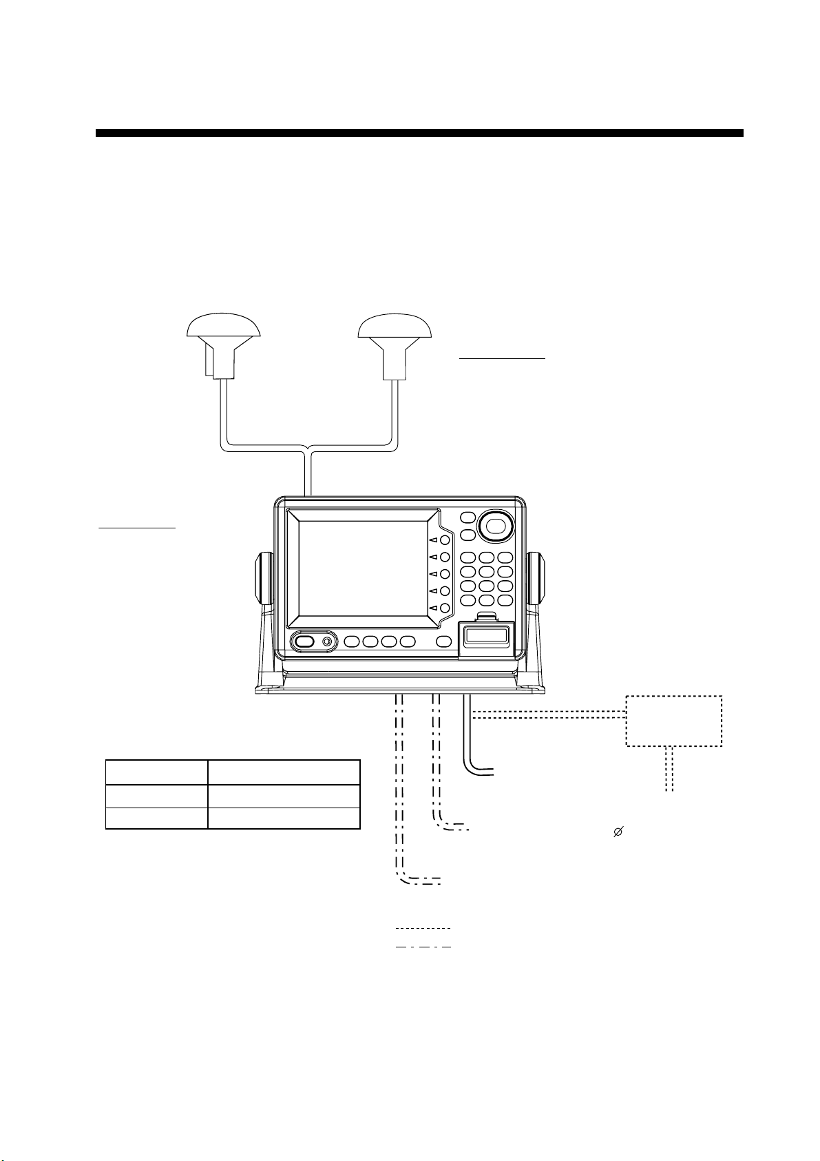
SYSTEM CONFIGURATION
Ship's mains
12–24 VDC
External equipment
(Autopilot, etc.)
DGPS beacon receiver
Antenna unit
Receives signal from
GPS satellite and beacon
reference station (GP-1850WD
only).
Display unit
Ship's position is
calculated in longitude
and latitude from signal
received from the antenna unit and displayed
on the screen.
Antenna unit GPA-017
(GP-1850W)
Antenna unit GPA-019
(GP-1850WD)
Category of Units
Unit Category
Display unit
Antenna unit
Exposed to weather
Exposed to weather
: Option
: Local Supply
Rectifier
RP-62
Ship's mains
100/110/115/220/230 VAC
1 , 50/60 Hz
The GP- 1850W/1850 WD mainly consists of a display uni t and a G P S antenna. A DGPS
beacon receiver is provided inside the display unit for GP-1850 WD ty pe. The mini chart
card drive in the display unit loads electronic c har ts. Ex ternal equipment which m ay be
connected include an autopilot and a DGPS beacon rec eiver (GP-1850W).
i
Page 6
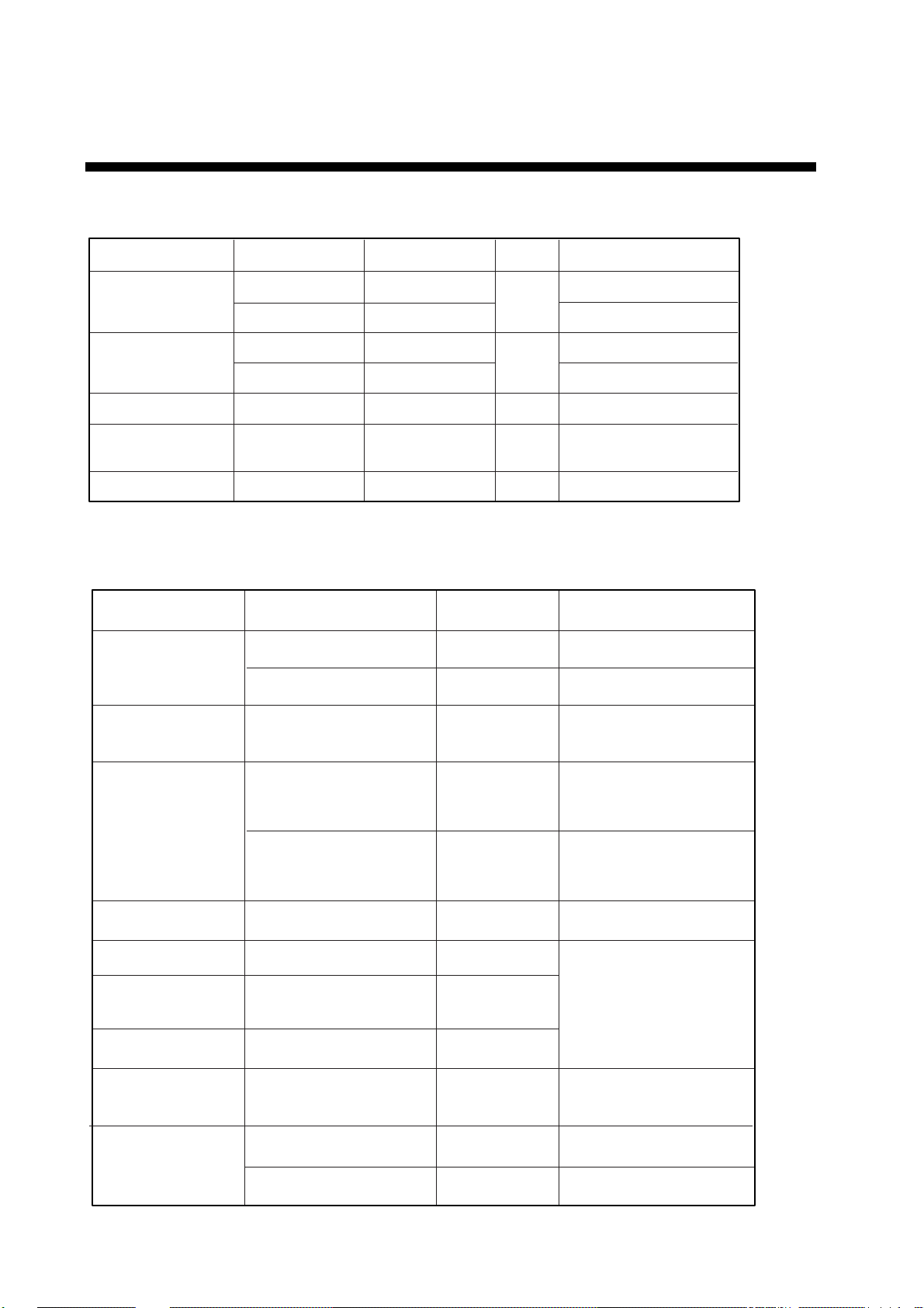
EQUIPMENT LISTS
Standard supply
Name Type Code No. Qty Remarks
Display Unit
Antenna Unit
Spare Parts* SP14-02501 004-375-260
Installation
Materials*
Accessories*
GP-1850W-E GP-1850WD-E GPA-017 GPA-019 for GP-1850WD
CP14-05200 000-041-496 1
FP14-02410 000-041-535 1 FP14-02401, FP14-02403
-
*: Refer to Pac k ing list at the end of this m anual.
Optional equipment
Name Type Code No. Remarks
DGPS Beacon
receiver kit
Antenna cable assy. TNC-PS-3D-15 000-133-670
GR-7000A-1650-10N-019 000-041-650 GPA-019, GR-7000A
GR-7000A-1650-15N-019S 000-041-653 GPA-019S, GR-7000A
1
for GP-1850W
1
1
Fuse
Power cable, cable assy.
15 m, for antenna cable
extension
CP20-01700 004-372-110
Antenna cable set
CP20-01710 004-372-120
Cable Assy. MJ-A7SPF0003-050 000-136-730-01
Mast mount fixture CP20-0111 004-365-780
Right-angle antenna
base
L-angle antenna base No.13-QA310 000-803-240
Antenna base
for rail mounting
Antenna Unit
No.13-QA330 000-803-239
No.13-RC5160 000-806-114
GPA-019S
GPA-017S
-
-
8D-FB-CV *30M* and
CP20-01701, for antenna
cable extension
8D-FB-CV *50M* and
CP20-01701, for antenna
cable extension
for antenna unit mounting
GP-1850WD
GP-1850W
ii
Page 7

Optional equipment (con’t)
Name Type Code No. Remarks
EQUIPMENT LISTS
000-013-484 for 100 VAC
000-013-485 for 110 VAC
Rectifier
Cable Assy.
Remote controller RMC-185-E 004-375-300
RAM Card 00RAM02MC-004 004-371-790
C-MAP
modification kit
PR-62
000-013-486 for 220 VAC
000-013-487 for 230 VAC
MJ-A6SPF0011-050 000-132-244
MJ-A6SPF0011-100 000-132-336
MJ-A6SPF0012-050 000-134-424
MJ-A6SPF0012-100 000-133-817
1650/1850-MAP 004-376-420
for radar,
6P-4P, 5 m
for radar,
6P-4P, 10 m
for navaid or E/S, 6P-6P,
5 m
for navaid or E/S, 6P-6P,
10 m
Conttoller, vinyl cover,
battery
2MB
iii
Page 8

EQUIPMENT LISTS
v
This p age is intentionally left blank.
i
Page 9
1. INSTALLATION
1.1 Installation of Display Unit
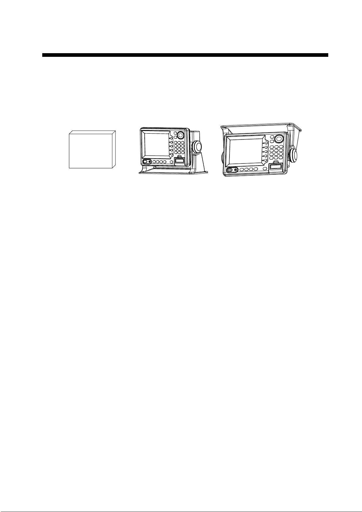
Mounting considerations
The dis play unit can be i ns talled on a tabletop, on the overhead or flush m ounted in a
console or p anel.
OverheadTabletopHard Cover
Tabletop, overhead mounting methods
When select ing a mounting location f or the display unit k eep the followi ng in mind:
•
Keep the display unit out of dir ec t sunlight.
•
The temper ature and humidity s hould be moderat e and s table.
•
Locate the unit away from exhaust pi pes and vents .
•
The mounting location should be well ventilated.
•
Mount the unit where s hoc k and vibration ar e m inimal .
•
Keep the uni t away elec tromagnetic field generating equipment such as motor, generator.
•
For maint enance and checking purposes, leave s uffi ci ent space at the sides and rear of
the unit and leave slack in cables.
•
A magnetic c om pass wil l be aff ec ted if placed too close to the di s play unit. O bs er ve the
following compass safe distances to pre vent distur bance to the magnetic com pass:
Standard com pass: 0.5 m eters
St eer ing compass: 0.3 met er s
1
Page 10
1. INSTALLATION
•
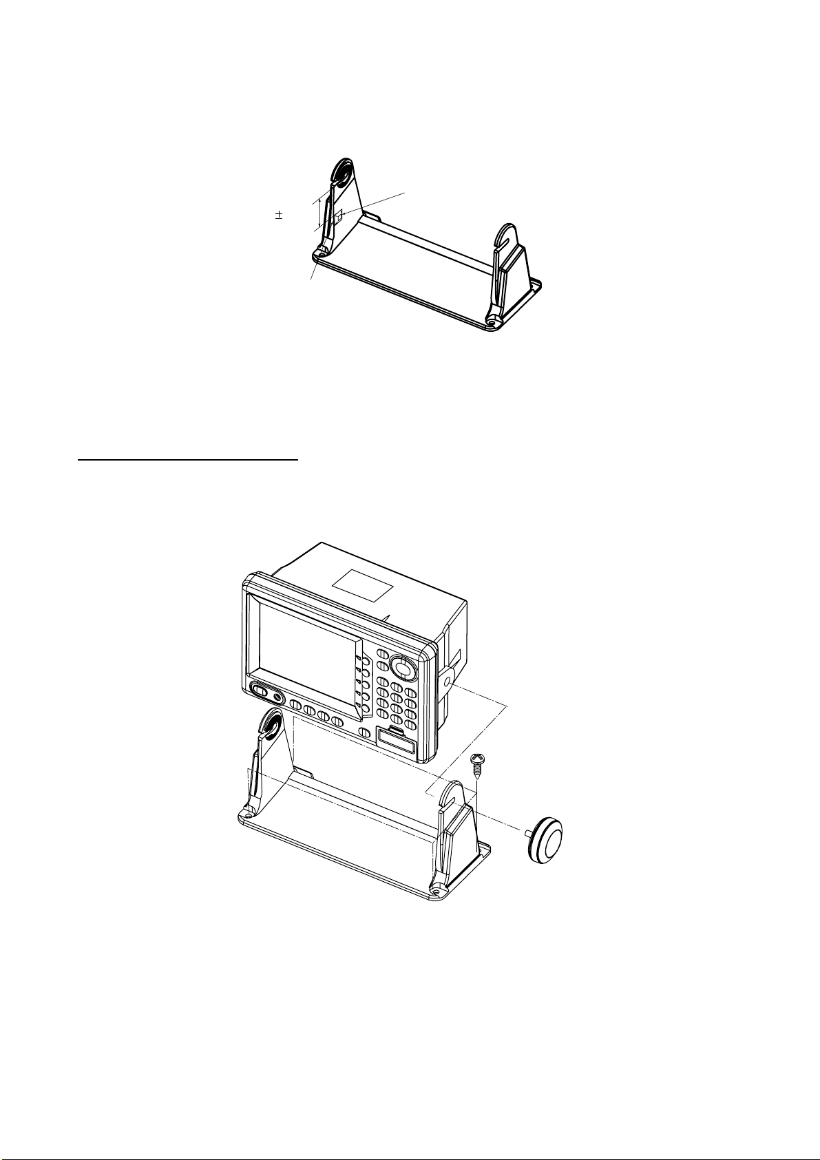
Rubber foot whic h abs or b vi br ation (supplied) maybe att ac hed as below if vibration is a
problem.
Rubber foot
45 5mm
Aline with edge
of hanger.
TM-166 No.18 black
Mounting procedure
Follow the procedure below to m ount the display unit on a t abletop or the over head.
T abletop, overhead mounting
1. Fix the hanger by four tapping screws 5 X 16.
2. Screw knob bol ts in dis play unit, set it to hanger, and ti ghten knob bolts.
3. Attach hard cover to protect LCD.
WARNING
2
Tabletop, overhead mounting of display unit
Page 11
1. INSTALLATION
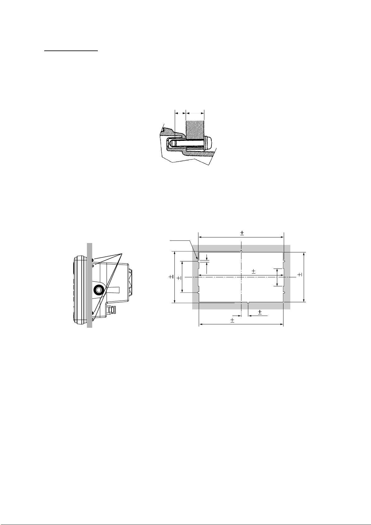
Flush mounting
Note: Use supplied p an head screws when the thickness of the bulkhead i s from 11 to 14
mm. For bulkhead which exceeds 14 mm in thickness the length of the pan head
screw s s hould be bulkhead thickness plus 7.3±1.5 m m . Also the length of B should
max. 7mm.
BA
1. Prepare a cutout in the mount ing location whose dim ens ions are as sh own on the next
page.
2. Fix the display unit by six pan head screws M4 X 20. Refer to the outline drawi ng on
page D-2.
242 0.5
244 1
15 0.5
238 1
(Cutout for flush mount)
50
143 1
Flush mount
Pan head screws
6-R2.25
89 0.5
147 0.5
4.5
Flush mount ing of display unit
3
Page 12
1. INSTALLATION
1.2 Installation of Antenna Unit
Mounting considerations
Install the antenna u nit referr ing to the i ns tallati on diagr am on page D- 3 or D- 4. When
selecting a mounting location f or the antenna un it, keep in mind the foll owing points:
•
Select a location out of the radar beam. The radar beam will obs truct or prevent r ec eption
of the GPS s atellit e si gnal.
•
The loc ation should be well away from a V HF antenna. A GP S r ec eiver is int er fered by a
harmonic wave of a VHF anten na.
•
There should be no interf er ing object withi n the line-of-si ght to the satellites. Objects
within line-of-sight to a satellite, for ex am ple, a mast, may block reception or prolong
acquisition time.
•
Mount the antenna unit as high as possible. Mounti ng the antenna u nit as high as
possible k eeps it free of interfer ing objects and w ater s pr ay, which can inter r upt reception
of GPS sat ellite signal if the water freezes.
•
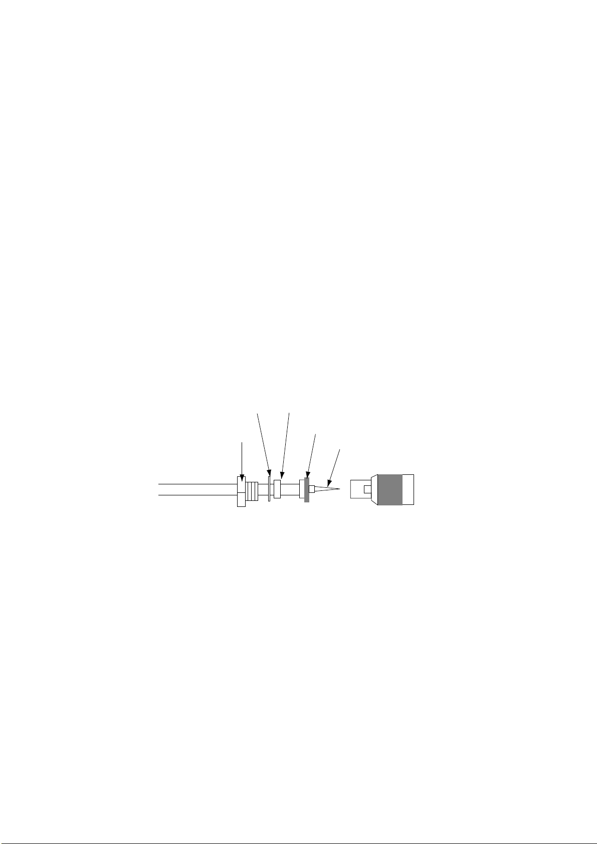
If the antenna c able is to be passed through a hole which is not large enough to pass the
connector, you may unfasten the connector w ith a needle nose pliers and 3/ 8- inch
open-end wrench. Refasten it as s hown in the figure b elow after running the cable
through the hole.
Gasket (reddish brown)Washer
Clamp nut
How to assemble the connec tor
Shield
Center pin (soldered)
Connector shell
4
Page 13
2. WIRING
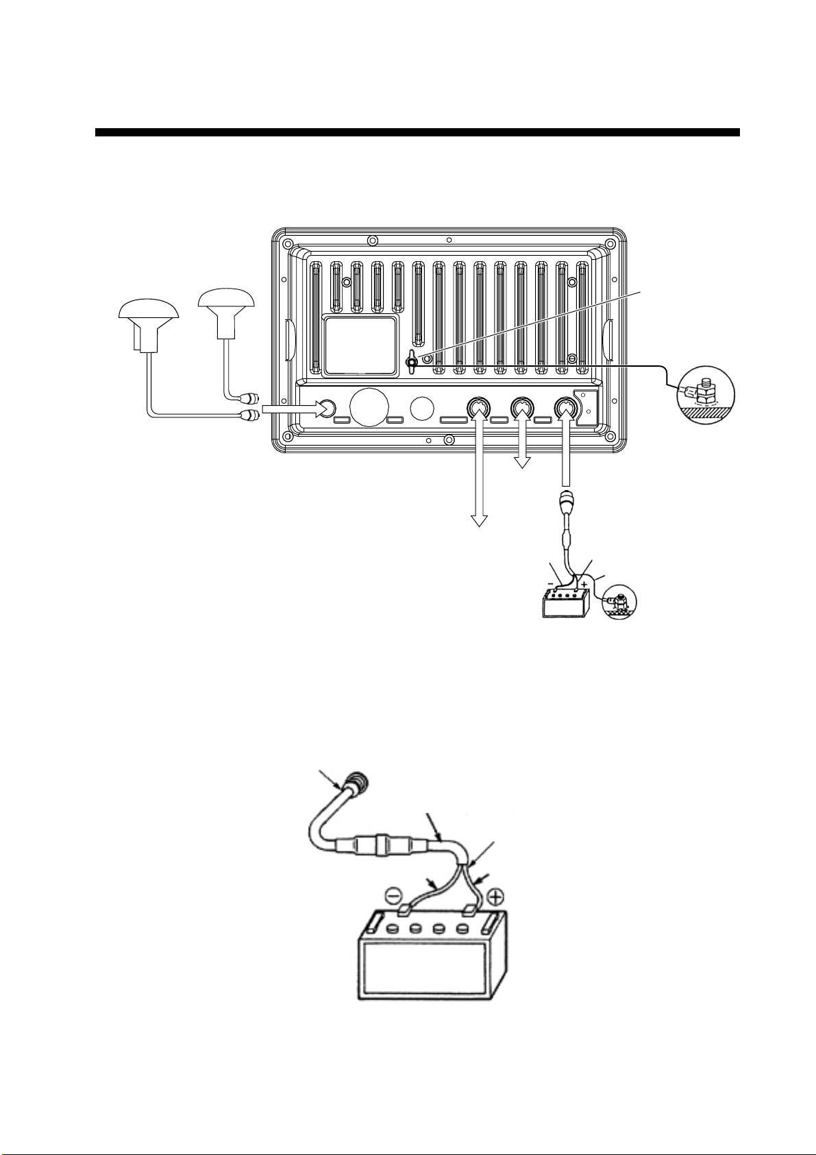
All wiring are termi nated at the rear of the display unit.
Display unit
Antenna unit
GPA-019
(GP-1850WD)
GPA-017
(GP-1850W)
ANT XDR
DGPS beacon receiver
(option for GP-1850W,
RS-232C only)
TEMP/SPD
Display unit, rear vi ew
DGPS
External
equipment
NMEA
Black
+ GND
1 3
2
-
12 - 24
VDC
White
Earth terminal
Ground
Shield
Power cable
Connect the power cable to the power connector. Connect the leads to the bat tery (12 or 24
VDC); white to plus ( + ) term inal and blac k to minus(-) term inal.
Cable connector
Power cable
w/fuse (5A)
Lead wire
Black
BATTERY
Connecti ng the power cab le to the battery
White
5
Page 14
2. WIRING
Antenna unit
Connect the antenna cable to the ANT connector.
Ground
The dis play unit contains several CP Us . While they are operati ng, they radiate noise, which
can interf er e with radio equipment. Ground the unit to prevent interferenc e. The gr ounding
wire should be 1.25 sq or l arger and as short as possible. Connect the gr ounding wire to
ship's ground. On a fiberglass boat , it is best t o ins tall a ground plate that measures about
20 cm by 30 cm on the outsi de of the hull bottom to provide a gr ound point. If this i s not
practical, the engi ne block can be used.
CAUTION
Ground the equipment to
prevent electrical shock
and mutual interference.
Note: Use a “closed” lug to m ak e the ground c onnection at the display unit. Do not use an
“open-type” lug (
).
Extendin g an te nn a c ab le le ng th
The standard cable is 10 m long. F or ex tension, in case of the G PA-019S or GPA-017S , an
antenna cabl e s et of 15m, 30 m or 50 m is available. Extension cable cannot be used with
the GPA-017 or GPA-019.
Cable length Necessary par ts Code No.
15 m TNC-PS-3D- 15 000-133-670
30 m CP 20-01700 004-372-110
50 m CP 20-01710 004-372-120
6
Page 15

2. WIRING
Extension cable li ne-up (in case o f 15 m, 30 m or 50 m)
Fabricat e the end of the antenna cable and att ac h the coaxial c onnec tor. Det ails are shown
on the page 8.
Antenna unit
GPA-019S/017S
Conversion
cable assy.
: Connector
1 m
Antenna cable
30 m or 50 m 1 m
Fabricate locally. (See the page 8.)
To display unit
Cable ext ens ion (CP20-01700, CP20- 01710)
Antenna unit
GPA-019S/GPA-017S
: Connector
Antenna cable
15 m
To display unit
Cable ext ens ion (TNC-PS- 3D-15)
Waterproofing connector
Wrap connector with vulcaniz ing tape and t hen vinyl tape. Bi nd the tape end w ith cable- tie.
Waterpr oofing connec tor
7
Page 16

2. WIRING
How to att ach the N-P - 8DF B connector
Outer sheath
Cover with heat-shrink tubing and heat.
Armor
30
Clamp
nut
Dimensions in millimeters.
Inner sheath shield
50
Gasket
(reddish
brown)
30
10
Clamp
Aluminum foil
Remove outer sheath and armor by the dimensions
shown left.
Expose inner sheath and shield by the dimensions
shown left.
Cut off insulator and core by 10mm.
Twist shield end.
Ship on clamp nut, gasket and clamp as shown left.
Trim shield here.
Trim aluminum
tape foil here.
Clamp nut
Insulator
1
5
Pin
Shell
Fold back shield over clamp and trim.
Cut aluminum foil at four places, 90° from one
another.
Fold back aluminum foil onto shield and trim.
Expose the insulator by 1mm.
Expose the core by 5mm.
Slip the pin onto the conductor. Solder them together
through the hole on the pin.
8
Insert the pin into the shell. Screw the clamp nut into
the shell.
Solder through
the hole.
(Tighten by turning the clamp nut. Do not tighten by
turning the shell.)
Fabricat ion of coax ial cable
Page 17

3. INITIAL SETTINGS
3.1 NMEA Setting
NMEA port
This set ting should be done when conne c ting with other equipm ent, autopilot, radar or
remote display.
1. Press the [ME NU] key.
2. Press the CONFIGURATION sof t key.
3. Press the SET UP NMEA PO RT1 soft key.
4. Press the cursor pad to select FORMAT.
5. Press the EDIT soft k ey to display the f ollowing window.
▲
DGPS 3D
Output for mat window (PORT 1)
6. Select NMEA versi on depending on the speci fication of the equipment connected. T he
selected item is indicated by blac k button.
7. Press the ENTER soft key.
8. Press the [PLOT] key to return to the plotter display.
OUTPUT FORMAT
▲
NMEA0183 Ver1.5
NMEA0183 Ver2.0
▼
SETUP
PORT1
ENTER
CANCEL
9
Page 18

3. INITIAL SETTINGS
DGPS port
Set the following when connecting with DG P S beacon r ec eiver GR-80 or the DGPS beacon
receiver is incorporated, PC to the DG P S por t.
Note: Signal level for DGPS port i s RS 232C.
1. Press the [MENU] key.
2. Press the CONFIGURATION soft k ey.
3. Press the SETUP NMEA/DGPS PORT 2 soft key.
4. Selec t FORMAT, and then press the EDIT soft key.
The following window appears.
▲
FORMAT NMEA 0183
DGPS 3D
OUTPUT FORMAT
▲
NMEA0183 Ver1.5
NMEA0183 Ver2.0
RTCM104 (EXTRN)
RTCM104 (INTRN)
RTCM104 (OUTPUT)
▼
VER 1.5
▲▲▲
SETUP
PORT2
ENTER
CANCEL
Output for mat window (PORT 2)
5. Selec t NMEA version. The selected item is indicated by black button.
NMEA0183 Ver1.5/2.0: Select one when connecting PC or RS-232C equipment.
RTCM104 (EXTERN): Select this when connecting external DGPS beacon receiver.
RTCM104 (INTRN): Select this for built in internal DGPS beacon receiver.
RTCM104 (OUTPUT): Select this when outputting differential data of the internal
DGPS beacon receiver to other GPS navigator.
Note 1: Note that you cann ot setup sentences when you selec t RTCM104 at the form at.
Note 2: For RS- 422 format, the level converter (IF-1432) is r equired for connection of
external equipment.
6. Press the ENTER soft key.
7. Press the [PLOT] key to fini s h.
10
Page 19

3. INITIAL SETTINGS
3.2 Output Data Sentences
Select out put data sent ences for external equipment as follows.
1. Press the [ME NU] key.
2. Press the CONFIGURATION sof t key.
3. Press the SET UP NMEA PO RT1 soft key.
4. Press the SELECT SNTNC. soft key to display the SELECT SENTENCE window.
▲
DGPS 3D
SELECT SENTENCE
▲
AAM
APB ON
BOD
BWR*
GGA
GLL ON
RMA
RMB ON
RMC ON
VTG ON
WPL
XTE
ZDA ON
*: BWR for Rhumb line
BWC for Great circle
Select sentence window
5. Select data s entence you want to out put.
6. Press the ON/OFF soft key. To output data, select ON.
7. Repeat to select other sentences.
8. Press the RETURN s o ft key.
9. Press the [PLOT] key to retur n the plotter display.
SELECT
SNTNC.
ON/OFF
RETURN
11
Page 20

3. INITIAL SETTINGS
Input/Output data sentences
Port Format Data Remarks
Input
NMEA-0183
NMEA
Output
Input
DGPS
Output
Ver. 2.0
Ver. 1.5
IEC1162
NMEA-0183
Ver. 2.0
Ver. 1.5
RS232C
RTCM104
TLL*1, MTW, WPL*1, DBT/DPT
AAM, APB, BOD, BWC/BWR,
GGA, GLL, RMA, RMB, RMC,
VTG, WPL, XTE, ZDA, MTW,
GTD*2
TLL*1, MTW, WPL*1, DBT/DPT
AAM, APB, BOD, BWC/BWR,
GGA, GLL, RMA, RMB, RMC,
VTG, WPL, XTE, ZDA, MTW,
GTD*2
WPL: GP only
NMEA Ver 1.5: DBT
NMEA Ver 2.0: DPT
GREAT CIRCLE: BWC
RHUMB LINE: BWR
ylnoPG:LPW
TBD:5.1reVAEMN
TPD:0.2reVAEMN
GREAT CIRCLE: BWC
RHUMB LINE: BWR
*1: Cannot be input consecutively.
*2: Output automatically when LC or LA is selected.
3.3 Antenna Height
Enter height of antenna ab ove water. (Default setting: 5 m)
1. Press the [ME NU] key.
2. Press the GPS/DGPS/TD OPTIONS soft key.
3. Press the GPS SETUP OPTIONS soft key .
4. Select ANT. HEIGHT.
5. Press the EDIT soft key.
ANT. HEIGHT
0 0 5 m
Ant. height window
6. Enter the height (3 digits) of the ant enna above sea level using the numeric keys.
If you enter wrong antenna height, press the CLEAR soft key.
7. Press the ENTER soft key.
8. Press the [PLOT] key to retur n the plotter display.
12
Page 21

3. INITIAL SETTINGS
3.4 DGPS Setting
When extern al GPS beacon receiver (output: RS - 232C only ) is connected or the DG P S
beacon receiver is i nc or por ated, set the DGPS mode refer r ing to t he following procedure.
1. Press the [ME NU] key.
2. Press the GPS/DGPS/TD OPTIONS soft key.
3. Press the DGPS/WAAS SETUP OPTIONS soft key.
FORMAT NMEA 0183
DGPS/WAAS MODE OFF
BEACON FREQUENCY AUTO
BEACON BAUD RATE AUTO
WAAS SEARCH AUTO
CORRECTIONS DATA SET 02
DGPS/WAAS ALARM ON
DGPS 3D
VER 1.5
DGPS
WAAS
EDIT
RETURN
DGPS/WAAS opti ons window
4. Select DGPS/WAAS MODE and press the EDIT soft key.
5. Select DGPS or AUTO and press the ENTER soft k ey.
WAAS: W AAS data can be received.
AUTO: DGPS, WAAS or GPS dat a can be automatically received, The order of priority is
DGPS, WAAS and GPS.
Note: If the external DGPS beacon receiver GR-80 is connect ed to the GP-1850W , refer to
the interc onnec tion diagram below.
Connecti on with G R- 80
GP-1850W
DGPS
GR-80
DATA
(Set RS-232C)
> 1 >
> 2 >
RD
> 3 >
YEL
< 1 < TD-B
> 4 >
SD
SG
> 5 >
> 6 >
RED
BLU
< 3 < RD-B
< 7 < GND
> 7 >
MJ-A7SPF0003-050 cable
(option)
13
Page 22

3. INITIAL SETTINGS
6. Select BEACON FREQUENCY by the cursor pad.
7. Press the EDIT soft key to display the following message.
BEACON FREQUENCY
▲
AUTO
MANUAL 284.0 kHz
▼
▼
Beacon frequency window
8. Select AUT O or MANUAL by the cursor pad. When y ou s elect M A NUA L, operate the
cursor pad t o m ove the cursor to frequency dialog box. And press the cursor pad to
select t he frequency desired.
AUT O: DGPS reference stati on c an be s ear ched autom atically.
9. Press the [ENTER] key.
10. Select BEACON BAUD RATE by the cursor pad.
11. Press the EDIT soft k ey to display the following window. Beacon baud rate ca nnot be set
when BEACON FREQ UENTRY is set to AUTO.
BEACON BAUD RATE
▲
200
100
50
▼
Beacon baud r ate window
12. Sel ec t beacon baud r ate corresponding to DG P S r eference st ation to use.
13. Press the [ENT E R] key.
14. Press the [PLOT] key to return the plotter display.
14
Page 23

4. INCORPORATION OF DGPS BEACON RECEIVER KIT (for GP-1850W)
The DGPS beac on r ec eiver GR-7 000A can be incor porated in the GP-1850W to provide it
with DGPS c apability. T wo kinds of ki t are av ailable as s hown.
GR-7000A-1650-10N-019
GR-7000A-1650-15N-019S
Name Type Code No. Qty
Antenna Unit GPA-019 000-142-416 1
Beacon
Receiver
Connector
Assy.
Cable tie CV-100 000-570-322 2
Pan head
screws*
Screw* M3X12 SUS304 000-805-905 6
Cable Assy.*
Clamp HP-2N 000-570-000 1
Cable Assy.
Screw 3X8 SUS410 000-881-405 4
Cable Assy.*
* Not used
GR-7000A 000-143-249 1
PH6P-W-L240 000-141-548 1
M3X10 C2700W 000-881-405 4
S.FL2-2LP0.7-DWHT (121)
S.FL2-2LP0.7-DWHT (250)
S.FL2-2LP0.7-DWHT (175)
000-141-491 1
000-143-877 1
000-141-490 1
Name Type Code No. Qty
Antenna Unit GPA-019S 000-142-545 1
Beacon
Receiver
Cable Assy. TNC-PS-3D-15 000-133-670 1
Connector
Assy.
Cable tie CV-100 000-570-322
Pan head
screws*
Screw* M3X12 SUS304 000-805-905 6
Cable Assy.*
Clamp HP-2N 000-570-000 1
Cable Assy.
Screw 3X8 SUS410 000-802-951 4
Cable Assy.*
* Not used
GR-7000A 000-143-249 1
PH6P-W-L240 000-141-548 1
M3X10 C2700W 000-881-405 4
S.FL2-2LP0.7-DWHT (121)
S.FL2-2LP0.7-DWHT (250)
S.FL2-2LP0.7-DWHT (175)
000-141-491 1
000-143-877 1
000-141-490 1
2
15
Page 24

4. INCORPORATION O F DGPS BEACON RECEIVER KIT (for GP-1850W)
Disassembly
Procedure
1. Turn off the power. Wait at least one minute before opening the cover, to allow
capacitors to discharge.
2. Rem ove nuts at tached to DGPS, NMEA and power supply connectors at the rear of the
display unit.
Removing cover assembly
3. Rem ove nut and washer attached to ANT connector.
4. Rem ove ten screws at rear of the display unit to detach panel/chassis assembly from the
cover assembly.
16
Page 25

4. INCORPORATION O F DGPS BEACON RECEIVER KIT (for GP-1850W)
Installation of beacon receiver
Procedure
1. Dism ount chassis assembly from panel/chassis assembly by disconnecting the
connector and PH8P from J8 on MAIN Board shown in the figure below.
Remove two ties (CV-100).
Chassis assembly
PH8P
Connector
Panel assembly
Dismounting chassis assembly
2. Dism ount heat sink from chassis assembly by unfastening three screws on the ANLG
board, loosening a screw at TR fixing plate and disconnecting the connector of t he mini
pin coax cable.
ANLG board
Screws (3 X 8), 3pcs.
Mini pin coax cable
Heat sink
TR fixing plate
Chassis assembly
17
Page 26

4. INCORPORATION O F DGPS BEACON RECEIVER KIT (for GP-1850W)
Handling of Coaxial Cable
• Do not touch the connector with bare hands;
use gloves.
• Use radio pincers to remove, and pull out
straightly.
• Plug in connector straightly.
3. Fasten the GR-7000A (DGPS beacon receiver) to the heat sink with four 3X8 screws as
shown in the figure below.
Screws (3 X 8), 4pcs.
DGPS beacon receiver
GR-7000A
GN-8091
Installation of DGPS beacon receiver
4. Open the cover of GR-7000A to connect two coaxial cables shown below.
J2
J1
Mini pin coax. cable
J3
Piece of shrink tubing
Cable assy.
S.FL2-2LP0.7-D-WHT (250) (Supplied with DGPS kit)
From GN-8091
Connecting the coaxial cables in GR-7000A
18
Page 27

4. INCORPORATION O F DGPS BEACON RECEIVER KIT (for GP-1850W)
5. Close the cover of GR-7000A passing the two cables out through respective notches in
the cover.
6. Plug PH6P-W-L240 connector to J2 on the GR-7000A through the cover.
7. Wire cable assembly as shown in the figure below.
Reattach this tape as
shown right after the
DGPS connection.
To J8 of
ANLG Board
GN-8091
J2
GR-7000A
J1
J3
J2
Connector
PH6P-W-L240
Wiring the Cable assembly
8. Mount the ANLG board on the heat sink referring to step 2. Fasten cable assy.
S.FL2-2LP0.7-D-WHT (250), 8P connector cable and 6P connector cable by cable tie
(CV-100, supplied) as shown in the figure below. Fix cable assy. S.FL2-2LP0.7-D-WHT
(250) with the vinyl tape.
8P connector
MAIN Board
10 mm
6P connector
40 to 45 mm
ANLG Board
J8
10 mm
vinyl tape
GN-8091
40 to 45 mm
Cable
tie
Attaching cable tie
19
Page 28

4. INCORPORATION O F DGPS BEACON RECEIVER KIT (for GP-1850W)
9. Connect J1 of GR-7000A to J8 of ANLG board (Refer to previous page).
10. Mount chassis assembly on the panel assembly. Connect 8P connector and 6P
connector to Main board as shown in the figure below.
11. Reassemble the display unit.
20
Attaching chassis assembly
Remounting the cover
Page 29

4. INCORPORATION O F DGPS BEACON RECEIVER KIT (for GP-1850W)
Note: When reattaching the cover, confirm the following parts are attached.
Inside of the cover: Shield gasket, GN gasket (See t he figure below.)
•
On ANLG Board: Connector gasket (See the page 16.)
•
GN gasket
Shield gaskets
Checking the beacon receiver
1. Press the [MENU] key.
2. Press the CONFIGURATION soft key.
3. Press the SYSTEM MENU soft key.
4. Press the SELF TEST soft key.
5. Press the MEMORY•I/O TEST soft key to display the following message.
TEST
PROGRAM:OK
NO.1418260XX
SRAM:OK
DRAM:OK
PORT1:OK*
PORT2:OK*
*Special connections are required to check these ports.
Otherwise, "--"(bar) appears.
INTERNAL
BATTERY: OK
GPS
RECEIVER:OK
NO.48502370XX
BEACON
RECEIVER:OK
NO.08501781XX
NO.
RETURN
Memory, I/O Test Display
6. Confirm that BEACON RECEIVER: OK is displayed.
7. Press the RETURN soft key.
8. Press the [PLOT] key to return the plotter display.
21
Page 30

This page is intentionally left blank .
Page 31

1
C4425-Z02-A
A - 1
Q'TY
1/1
1
14CP-X-9852 -0
DESCRIPTION/CODE №
MJ-A6SPF0003-050
OUTLINE
NAME
ケーブル組品MJ
000-117-603
CABLE ASSY.
MJ-A3SPF0013-035
ケーブル組品MJ
000-129-613
CABLE ASSY.
GP-1850W (E017)
GP-1850W (E017)GP-1850W (E017)
GP-1850W (E017)
UNITUNIT
UNIT
1
GP-1850W-E
000-041-808
1
GPA-017
000-041-403
3
SP14-02501SP14-02501
SP14-02501
FGBO-A 5A AC125V
SPARE PARTSSPARE PARTS
SPARE PARTS SP14-02501
000-549-064
1
FP14-02401FP14-02401
FP14-02401
FP14-02401
ACCESSORIESACCESSORIES
ACCESSORIES FP14-02401
004-375-270
6
FP14-02403FP14-02403
FP14-02403
M4X20 SUS304
ACCESSORIESACCESSORIES
ACCESSORIES FP14-02403
000-804-742
5X16 SUS304 1種
4
2
000-805-494
TM-166 No.18 クロ
000-808-732
OTHER INSTALLATION MATERIALSOTHER INSTALLATION MATERIALS
OTHER INSTALLATION MATERIALS
PACKING LIST
PACKING LISTPACKING LIST
PACKING LIST
NAME OUTLINE Q'TYDESCRIPTION/CODE №
ユニット
ユニットユニット
ユニット UNIT
指示器
DISPLAY UNIT
空中線部
ANTENNA UNIT
予備品
予備品予備品
予備品 SPARE PARTS
ヒューズ
FUSE
付属品
付属品付属品
付属品 ACCESSORIES
ハードカバー組品
HARD COVER ASSY.
付属品
付属品付属品
付属品 ACCESSORIES
+ナベセムスネジB
WASHER HEAD SCREW
+トラスタッピンネジ
+TAPPING SCREW
ゴムアシ
その他工材
その他工材その他工材
RUBBER FOOT
その他工材 OTHER INSTALLATION MATERIALS
(略図の寸法は、参考値です。 DIMENSIONS IN DRAWING FOR REFERENCE ONLY.)
(略図の寸法は、参考値です。 DIMENSIONS IN DRAWING FOR REFERENCE ONLY.)(略図の寸法は、参考値です。 DIMENSIONS IN DRAWING FOR REFERENCE ONLY.)
Page 32

1
C4425-Z05-A
A - 2
Q'TY
1/1
1
14CP-X-9855 -0
DESCRIPTION/CODE №
MJ-A6SPF0003-050
OUTLINE
NAME
ケーブル組品MJ
000-117-603
CABLE ASSY.
MJ-A3SPF0013-035
ケーブル組品MJ
000-129-613
CABLE ASSY.
GP-1850WD(E019)
GP-1850WD(E019)GP-1850WD(E019)
GP-1850WD(E019)
UNITUNIT
UNIT
1
GP-1850WD-E
1
000-041-812
GPA-019
000-142-416
3
SP14-02501SP14-02501
SP14-02501
FGBO-A 5A AC125V
SPARE PARTSSPARE PARTS
SPARE PARTS SP14-02501
000-549-064
1
FP14-02401FP14-02401
FP14-02401
FP14-02401
ACCESSORIESACCESSORIES
ACCESSORIES FP14-02401
004-375-270
6
FP14-02403FP14-02403
FP14-02403
M4X20 SUS304
ACCESSORIESACCESSORIES
ACCESSORIES FP14-02403
000-804-742
5X16 SUS304 1種
4
2
000-805-494
TM-166 No.18 クロ
000-808-732
OTHER INSTALLATION MATERIALSOTHER INSTALLATION MATERIALS
OTHER INSTALLATION MATERIALS
PACKING LIST
PACKING LISTPACKING LIST
PACKING LIST
NAME OUTLINE Q'TYDESCRIPTION/CODE №
ユニット
ユニットユニット
ユニット UNIT
指示器
DISPLAY UNIT
空中線部
ANTENNA UNIT
予備品
予備品予備品
予備品 SPARE PARTS
ヒューズ
FUSE
付属品
付属品付属品
付属品 ACCESSORIES
ハードカバー組品
HARD COVER ASSY.
付属品
付属品付属品
付属品 ACCESSORIES
+ナベセムスネジB
WASHER HEAD SCREW
+トラスタッピンネジ
+TAPPING SCREW
ゴムアシ
その他工材
その他工材その他工材
RUBBER FOOT
その他工材 OTHER INSTALLATION MATERIALS
(略図の寸法は、参考値です。 DIMENSIONS IN DRAWING FOR REFERENCE ONLY.)
(略図の寸法は、参考値です。 DIMENSIONS IN DRAWING FOR REFERENCE ONLY.)(略図の寸法は、参考値です。 DIMENSIONS IN DRAWING FOR REFERENCE ONLY.)
Page 33

PACKING LIST
C4425-Z07-A
A - 3
PACKING LIST
PACKING LISTPACKING LIST
GP-1850WD(E)
GP-1850WD(E)
GP-1850WD(E)GP-1850WD(E)
14CP-X-9857 -0
1/1
N A M E
ユニット
ユニット UNIT
ユニットユニット
指示器
DISPLAY UNIT
予備品
予備品 SPARE PARTS
予備品予備品
ヒューズ
FUSE
付属品
付属品 ACCESSORIES
付属品付属品
ハードカバー組品
HARD COVER ASSY.
付属品
付属品 ACCESSORIES
付属品付属品
+ナベセムスネジB
WASHER HEAD SCREW
+トラスタッピンネジ
UNIT
UNITUNIT
SPARE PARTS SP14-02501
SPARE PARTSSPARE PARTS
ACCESSORIES FP14-02401
ACCESSORIESACCESSORIES
ACCESSORIES FP14-02403
ACCESSORIESACCESSORIES
O U T L I N E
DESCRIPTION/CODE №
GP-1850WD-E
000-041-812
FGBO-A 5A AC125V
000-549-064
FP14-02401
004-375-270
M4X20 SUS304
000-804-742
5X16 SUS304 1種
SP14-02501
SP14-02501SP14-02501
FP14-02401
FP14-02401FP14-02401
FP14-02403
FP14-02403FP14-02403
Q'TY
1
3
1
6
+TAPPING SCREW
ゴムアシ
RUBBER FOOT
その他工材
その他工材 OTHER INSTALLATION MATERIALS
その他工材その他工材
ケーブル組品MJ
CABLE ASSY.
ケーブル組品MJ
CABLE ASSY.
OTHER INSTALLATION MATERIALS
OTHER INSTALLATION MATERIALSOTHER INSTALLATION MATERIALS
4
000-805-494
TM-166 No.18 クロ
2
000-808-732
MJ-A6SPF0003-050
1
000-117-603
MJ-A3SPF0013-035
1
000-129-613
(略図の寸法は、参考値です。 DIMENSIONS IN DRAWING FOR REFERENCE ONLY.)
(略図の寸法は、参考値です。 DIMENSIONS IN DRAWING FOR REFERENCE ONLY.)
(略図の寸法は、参考値です。 DIMENSIONS IN DRAWING FOR REFERENCE ONLY.)(略図の寸法は、参考値です。 DIMENSIONS IN DRAWING FOR REFERENCE ONLY.)
Page 34

CODENO.
A - 4
CODENO.
CODENO.CODENO.
TYPE
TYPE
TYPETYPE
20AG‑X‑9404
‑1
1/1
工事材料表
工事材料表
工事材料表工事材料表
INSTALLATIONMATERIALS
番号
NO.
1
2
名 称
NAME
アンテナケーブル組品
ANTENNACABLEASSY.
ケーブル組品
CABLEASSY.
GP‑80,GP‑90,SC‑55,GP‑3500/F
GP‑1850,GP‑1650,FA‑100,GP‑1640/F
SC‑60/120,GD/GP‑280/680/380
略 図
OUTLINE
型名/規格
DESCRIPTIONS
8D‑FB‑CV*30M*
CODENO.
8D‑FB‑CV*50M*
CODENO.
000‑111‑547
000‑117‑599
数量
Q'TY
用途/備考
REMARKS
選択 TOBESELECTED
1
選択 TOBESELECTED
1
FURUNO ELECTRIC CO .,LTD.
(略図の寸法は、参考値です。 DIMENSIONSINDRAWINGFORREFERENCEONLY.)
(略図の寸法は、参考値です。 DIMENSIONSINDRAWINGFORREFERENCEONLY.)
(略図の寸法は、参考値です。 DIMENSIONSINDRAWINGFORREFERENCEONLY.)(略図の寸法は、参考値です。 DIMENSIONSINDRAWINGFORREFERENCEONLY.)
Page 35

工事材料表
A - 5
工事材料表
工事材料表工事材料表
INSTALLATIONMATERIALS
番号
NO.
1
名 称
NAME
変換ケーブル組品
CONVERTCABLEASSY.
略 図
OUTLINE
CODENO.
CODENO.
CODENO.CODENO.
TYPE
TYPE
TYPETYPE
型名/規格
DESCRIPTIONS
NJ‑TP‑3DXV‑1
CODENO.
004‑372‑420
CP20‑01701
000‑123‑809
数量
Q'TY
20AG‑X‑9405
用途/備考
2
‑1
1/1
REMARKS
ビニールテープ
2
VINYLTAPE
コネクタ(N)
3
CONNECTOR
絶縁テープ
4
SELF‑BONDINGTAPE
NO36002X19X10000
クロ エスロン
CODENO.
N‑P‑8DFB
CODENO.
Uテープ 0.5X19X5M
CODENO.
000‑835‑215
000‑111‑549
000‑800‑985
1
1
1
FURUNO ELECTRIC CO .,LTD.
(略図の寸法は、参考値です。 DIMENSIONSINDRAWINGFORREFERENCEONLY.)
(略図の寸法は、参考値です。 DIMENSIONSINDRAWINGFORREFERENCEONLY.)
(略図の寸法は、参考値です。 DIMENSIONSINDRAWINGFORREFERENCEONLY.)(略図の寸法は、参考値です。 DIMENSIONSINDRAWINGFORREFERENCEONLY.)
Page 36

Page 37

D-2
Page 38

Feb. 19, '03
D-3
Page 39

Feb. 19, '03
D-4
Page 40

Jan.5'04
H.Hayashi
D-5
Page 41

Page 42

GP‑1850W/1850WD
Y. Hatai
S-1
TITLE
GPS/DGPSプロッタ
相互結線図
NAME
名称
GPS/DGPS PLOTTER
INTERCONNECTION DIAGRAM
DGPS BEACON RECEIVER
RD
SD
YEL
REDアオBLU
キ
アカ
P
SD
NC
RD
RS‑232C
NMEA0183 in RS232C LEVEL *4
RS‑232C
SHIELD
P
7
65432
SG
SHIELD
RTCM104
NMEA0183 Ver1.5/2.0
*3
12‑24 VDC
J3
(+)
123
(‑)
SHIELD
NMEA0183 Ver 2.0/1.5
DGPSビーコン受信機
WHT
BLK
YEL
GRN
シロクロキ
P
TD‑A
GP‑1850W/WD
TD‑B
P
321
RD‑H
ミド
RD‑C
NC
654
SHIELD
*2
*3
MJ‑A7SPFD
J5
DGPS
J7
ANT
TNC‑P‑3
1
NC
MJ‑A7SPF0003,5m
NC
MJ‑A6SPF0007,10m
MJ‑A6SPF0012,5/10m
MJ‑A6SPF0011,5/10m
MJ‑A6SPF003,5m,φ6
*3
34
MJ‑A6SPF
J6
NMEA
DISPLAY UNIT
指示器
2
1m,φ5.3
NJTP‑3DXV‑1
*2 *3
N‑J‑3
N‑P‑8DFB
*2
8D‑FB‑CV
30/50m
(GP‑1850W)
(GP‑1850WD)
GPA‑019
GPA‑017
ANTENNA UNIT
空中線部
1
*2
10m,φ5.3
*3
TNC‑PS‑3D,15m,φ5.3
TNC‑P‑3
TNC‑J‑3
N‑P‑8DFB
*3
N‑J‑3
1m,φ5.3
NJTP‑3DXV‑1
*2 *3
TNC‑P‑3
TNC‑J‑3
*3
MJ‑A3SPFD
5A
BLK
クロ
シロWHT
MJ‑A3SPF0013,3.5m,φ8.0
12‑24 VDC
1256
DPYC‑1.5 *1
220/230VAC,
50/60Hz,1φ
100/110(115)/
(−)
(+)
整流器
*2
PR‑62
RECTIFIER
kg
E. MIYOSHI
MASS
TAKAHASHI. T
C4425‑C01‑ C
Aug. 24, '04
*1
IV‑1.25SQ.
GND
*1
IV‑8SQ
DRAWN
CHECKED
SCALE
APPROVED
DWG.No.
(GP‑1850W)
(GP‑1850WD)
GPA‑019S
GPA‑017S
0.2m,φ5.3
*4. OPTIONAL LEVEL CONVERTER REQUIRED FOR CURRENT LOOP OR RS422 OUTPUT.
*2. OPTION.
注記
*2)オプション。
*1)現地手配。
A
B
C
*3)コネクタは工場にて取付済み。
*4)カレントループ、RS‑422の接続にはオプションのレベル変換器が必要。
NOTE
*1. LOCAL SUPPLY.
*3. FITTED AT FACTORY.
Page 43

Page 44

9-52 Ashihara-cho,
*
0
*
0
Nishinomiya, 662-8580, JAPAN
Telephone : +81-(0)798-65-2111
Fax : +81-(0)798-65-4200
The paper used in this manual
is elemental chlorine free.
・FURUNO Authorized Distributor/Dealer
All rights reserved.
Printed in Japan
Pub. No. IME-44250-A2
(YOSH ) GP-1850W/1850WD
A : AUG 2002
.
A2 : AUG . 27, 2004
0080936710*
0080936710*
*00080936710**00080936710*
* 0 0 0 8 0 9 3 6 7 1 0 *
 Loading...