

Page 1

INSTALLATION MANUAL
COLOR DGPS/PLOTTER/SOUNDER
GP-1850DF
COLOR GPS/PLOTTER/SOUNDER
GP-1850F
Safety Instructions for the Installer .......................i
Equipment Lists .....................................................ii
System Configuration ...........................................iv
1. Installation of Standard Equipment ...............1-1
1.1 Installation of Display Unit ..............................................1-1
1.2 Installation of Antenna Unit .............................................1-3
1.3 Installation of Transducers ............................................... 1-4
1.4 Installation of Sensors ....................................................1-14
2. Wiring ...............................................................2-1
3. Initial Settings..................................................3-1
3.1 NMEA Setting ..................................................................3-1
3.2 Output Data Sentences .....................................................3-3
3.3 Antenna Height.................................................................3-4
3.4 Baud Rate Setting (GP-1850DF only)..............................3-4
3.5 Beacon frequency Setting (GP-1850DF only) .................3-5
3.6 Depth Adjustment.............................................................3-6
3.7 External Equipment Setup (Option) ................................. 3-7
3.8 Selecting the Echo Sounder Output Power ....................3-10
4. Installation of DGPS Beacon Receiver
(for GP-1850F) .................................................4-1
APPENDIX TRIDUCER 525ST-PWC/PWD .......AP-1
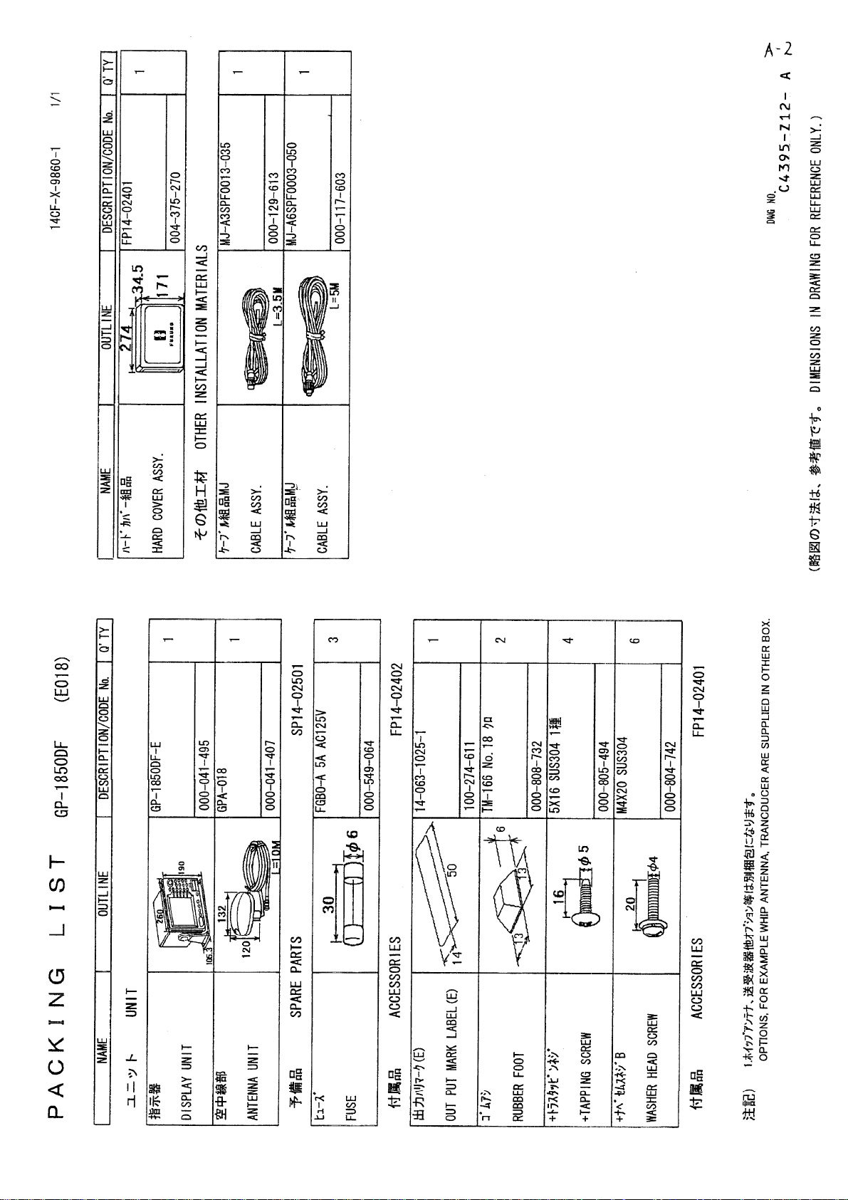
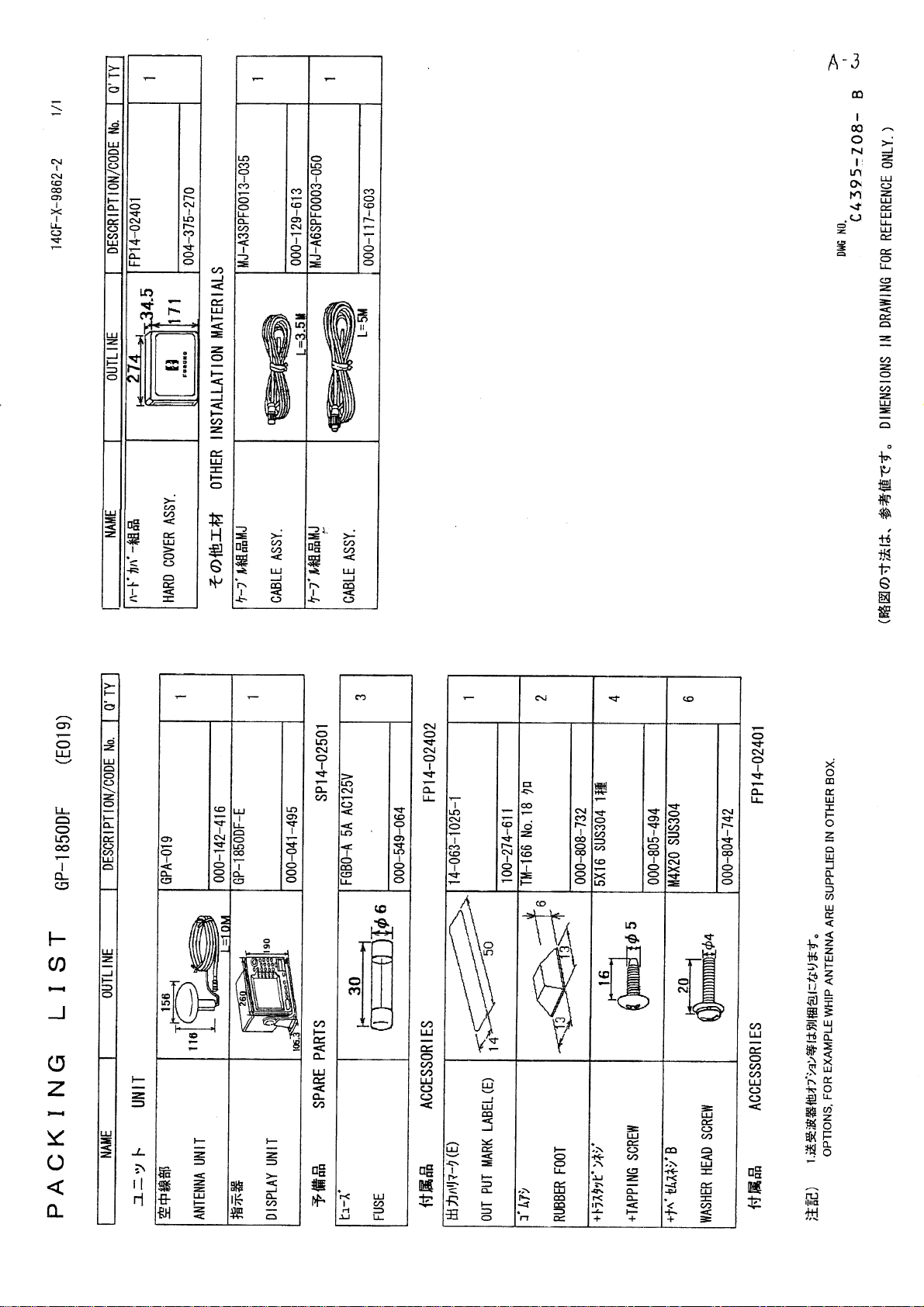
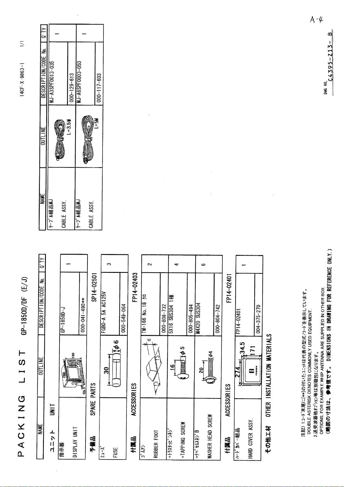
PACKING LIST .................................................... A-1
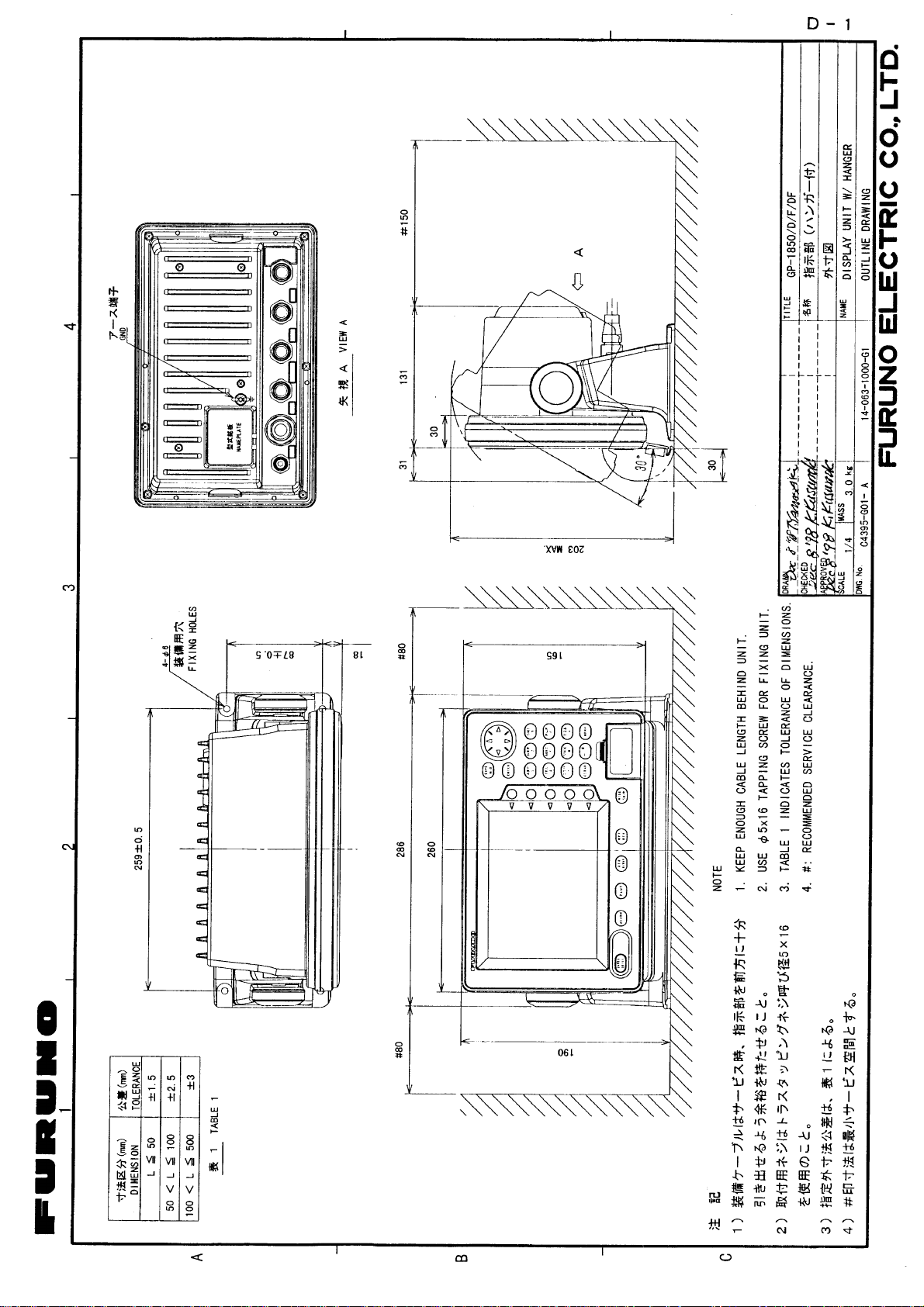
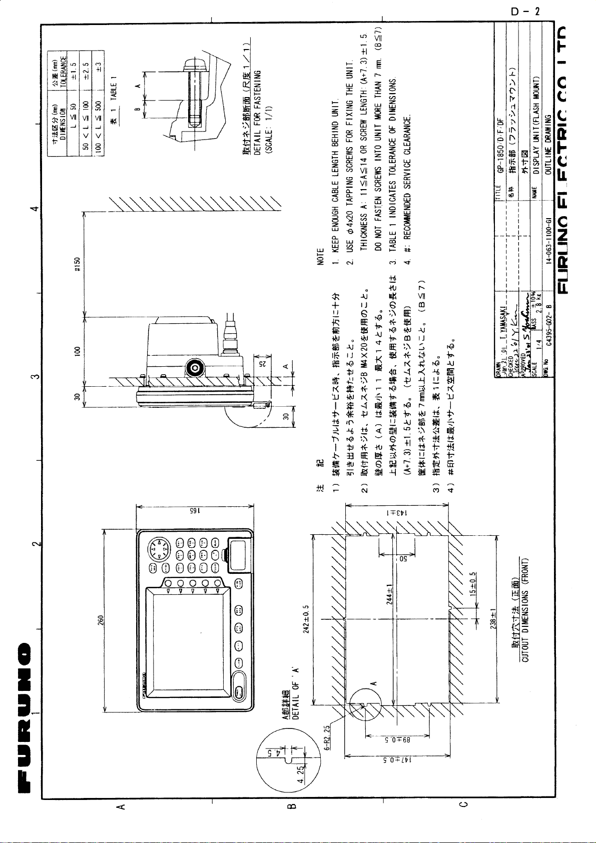
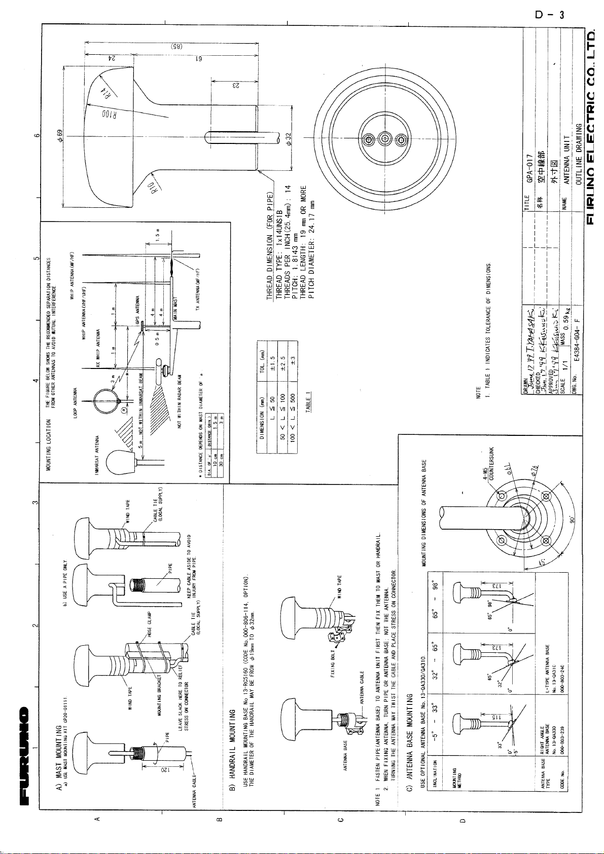
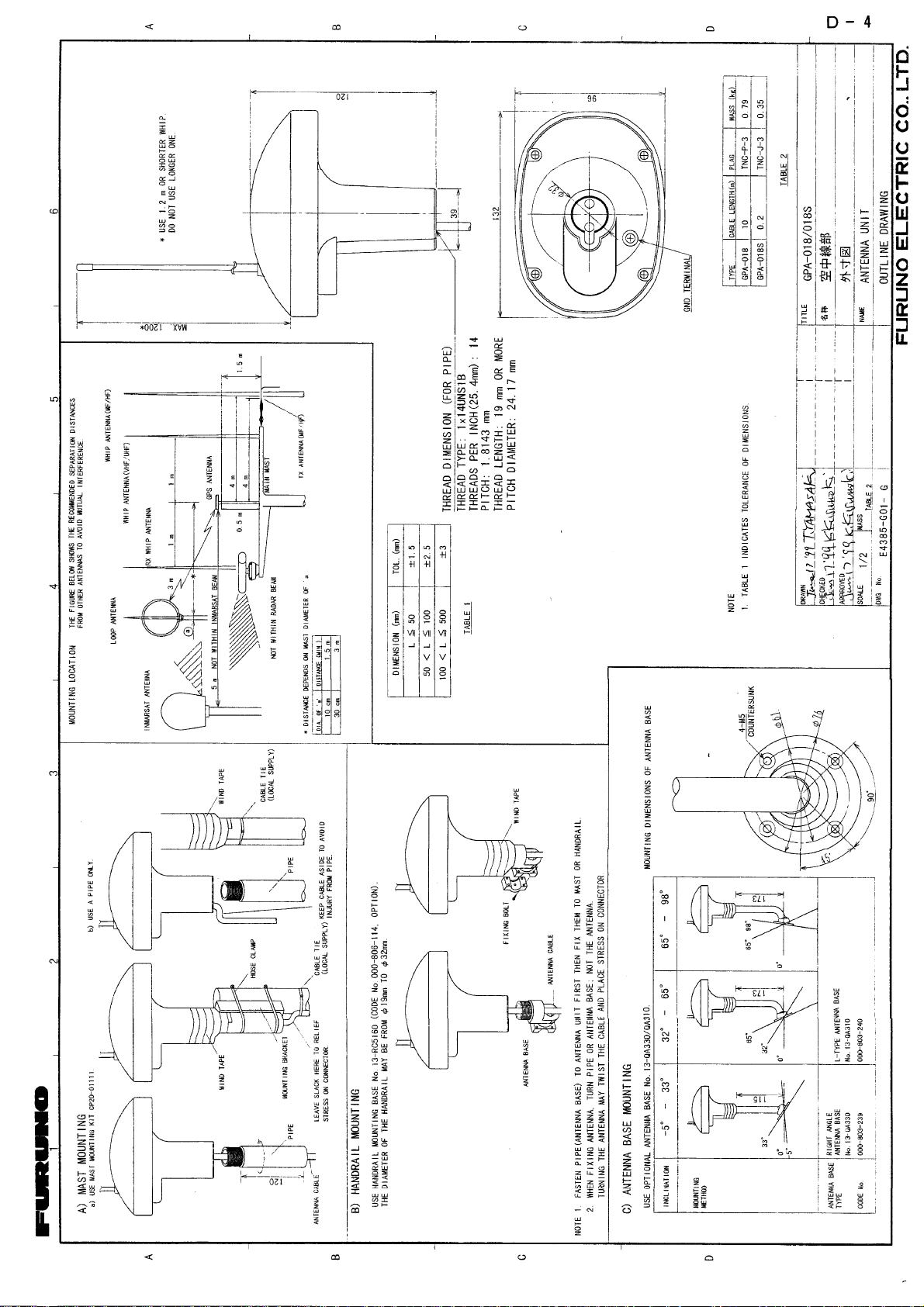
OUTLINE DRAWINGS......................................... D-1
INTERCONNECTION DIAGRAM ........................ S-1
SCHEMATIC DIAGRAM ...................................... S-2
Page 2
(
C
9-52, Ashihara-cho,
Nishinomiya, Japan
Telephone: 0798-65-2111
Telefax: 0798-65-4200
All rights reserved.
Printed in Japan
PUB. No. IME-43950-J
HIMA)
GP-1850F/1850DF
Your Local Agent/Dealer
FIRST EDITION : FEB. 1999
J : NOV. 01, 2001
Page 3
CAUTION
WARNING
SAFETY INSTRUCTIONS
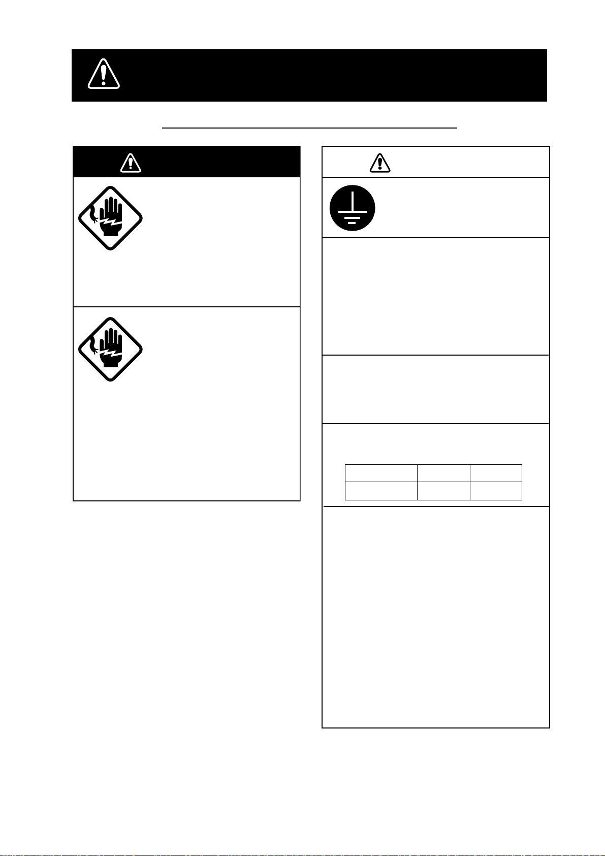
Safety Instructions for the Installer
WARNING
Do not work inside the
equipment unless totally
familiar with electrical
circuits.
Hazardous voltage which can
shock, burn or cause serious
injury exists inside the equipment.
Turn off the power at the
mains switchboard before
beginning the installation.
Post a sign near the switch
to indicate it should not be
turned on while the equipment is being installed.
Fire, electrical shock or
serious injury can result if the
power is left on or is applied
while the equipment is being
installed.
CAUTION
Ground the equipment to
prevent electrical shock
and mutual interference.
Confirm that the power supply voltage
is compatible with the voltage rating
of the equipment.
Connection to the wrong power supply
can cause fire or equipment damage. The
voltage rating appears on the label at the
rear of the display unit.
Use the correct fuse.
Use of a wrong fuse can cause fire or
equipment damage.
Keep the following compass safe
distance.
Standard Steering
Display Unit 0.98 m 0.74 m
When handling the transducer cable,
keep in mind the following points.
•
Keep the cable away from oil and
fuel.
•
Keep the cable away from the
place where it may be damaged
during the installation.
•
Do not paint the cable.
The sheath of the transducer cable is
made of chlorophrene rubber (or vinyl
chloride). Therefore, do not paint the
sheath with organic liquid (such as
toluene) since it may harm the sheath.
i
iiiiiiiiiiiii
Page 4
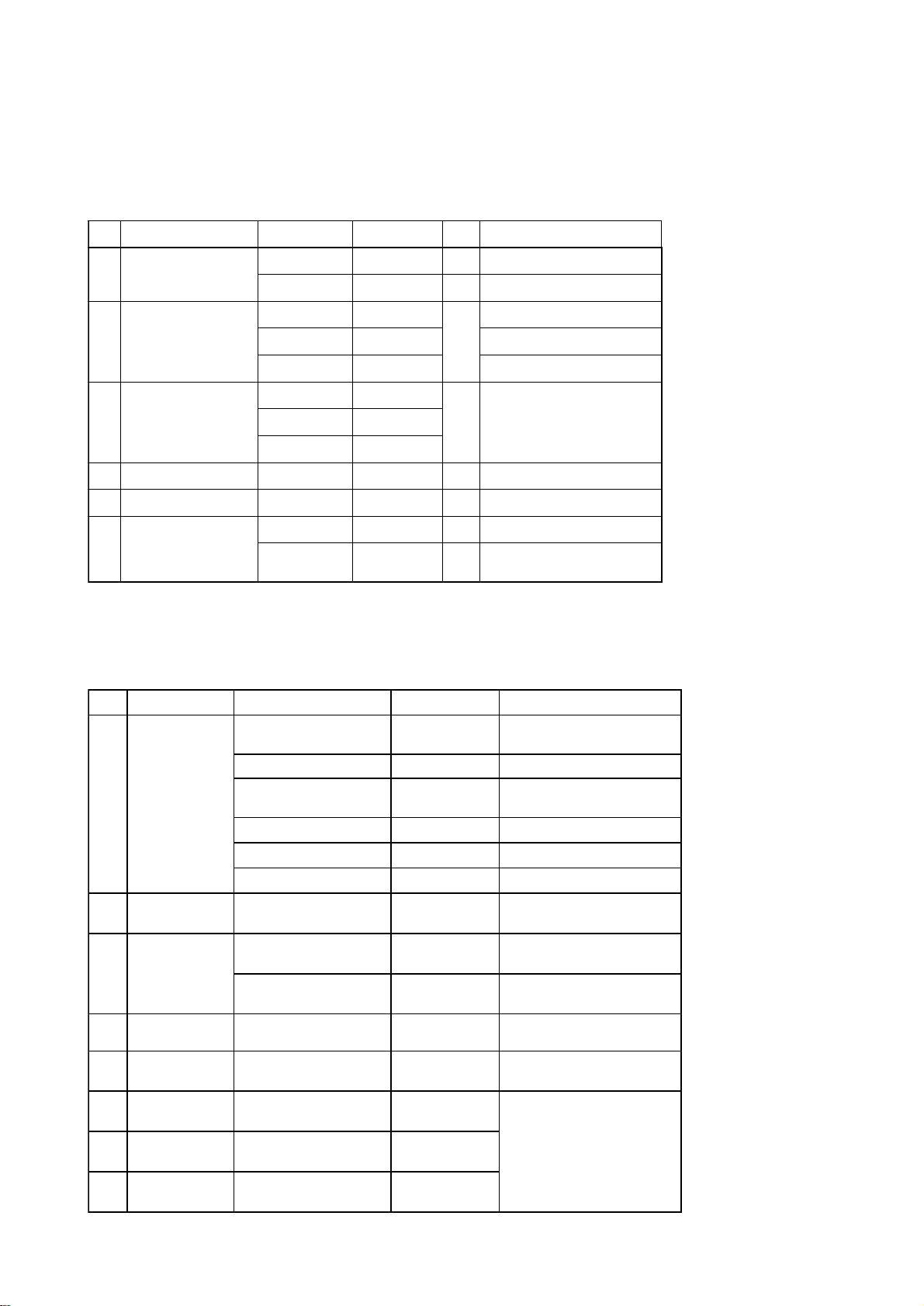
Equipment Lists
Standard supply
.oNemaNepyT.oNedoCytQskrameR
1tinuyalpsiD
2tinuannetnA
3recudsnarT
4straperapS10520-41PS062-573-4001esuF
5slairetamnoitallatsnI00250-41PC694-140-0001 .yssaelbaC,elbacrewoP
6seirosseccA
E-F0581-PG-1F0581-PGrof
E-FD0581-PG- FD0581-PGrof
710-APG810-APG- FD0581-PGrof
910-APG- FD0581-PGrof
DSP5-025521-510-000
DSM5-025721-510-000
10420-41PF072-573-4001revocdraH
20420-41PF051-673-4001
1
1.enotceles,tuptuoW006rofDWP5-025621-510-000
Optional equipment
.ONemaNepyT.oNedoCskrameR
810-A01-0581-208-RG894-140-000
810-N01-0581-208-RG405-140-000A0007-RG,810-APG
1
tik
2
3
.yssa
tes
reviecernocaeB
elbacannetnA
elbacannetnA
51-D3-SP-CNT076-331-000
00710-02PC011-273-400
01710-02PC021-273-400
S810-A51-0581-209-RG994-140-000
S810-N51-0581-208-RG505-140-000A0007-RG,810-APG
910-N01-0581-208-PG846-140-000A0007-RG,910-APG
S910-N51-0581-209-RG946-140-000A0007-RG,S910-APG
F0581-PGrof
,lebalkramtuptuo,swercS
noihsucrebbur
pihw,A0007-RG,810-APG
annetna
pihw,A0007-RG,S810-APG
annetna
elbacannetnarof,m51
noisnetxe
elbacannetnarof,m03
noisnetxe
elbacannetnarof,m05
noisnetxe
4.yssAelbaC050-3000FPS7A-JM10-037-631-000
5
6
8
tnuomtsaM
erutxif
elgna-thgiR
esabannetna
annetnaelgna-L
esab
esabannetnA
gnitnuomliarrof
1110-02PC087-563-400
033AQ-31.oN932-308-000
013AQ-31.oN042-308-000
0615CR-31.oN411-608-000
tinuannetnagnitnuomrof7
ii
Page 5
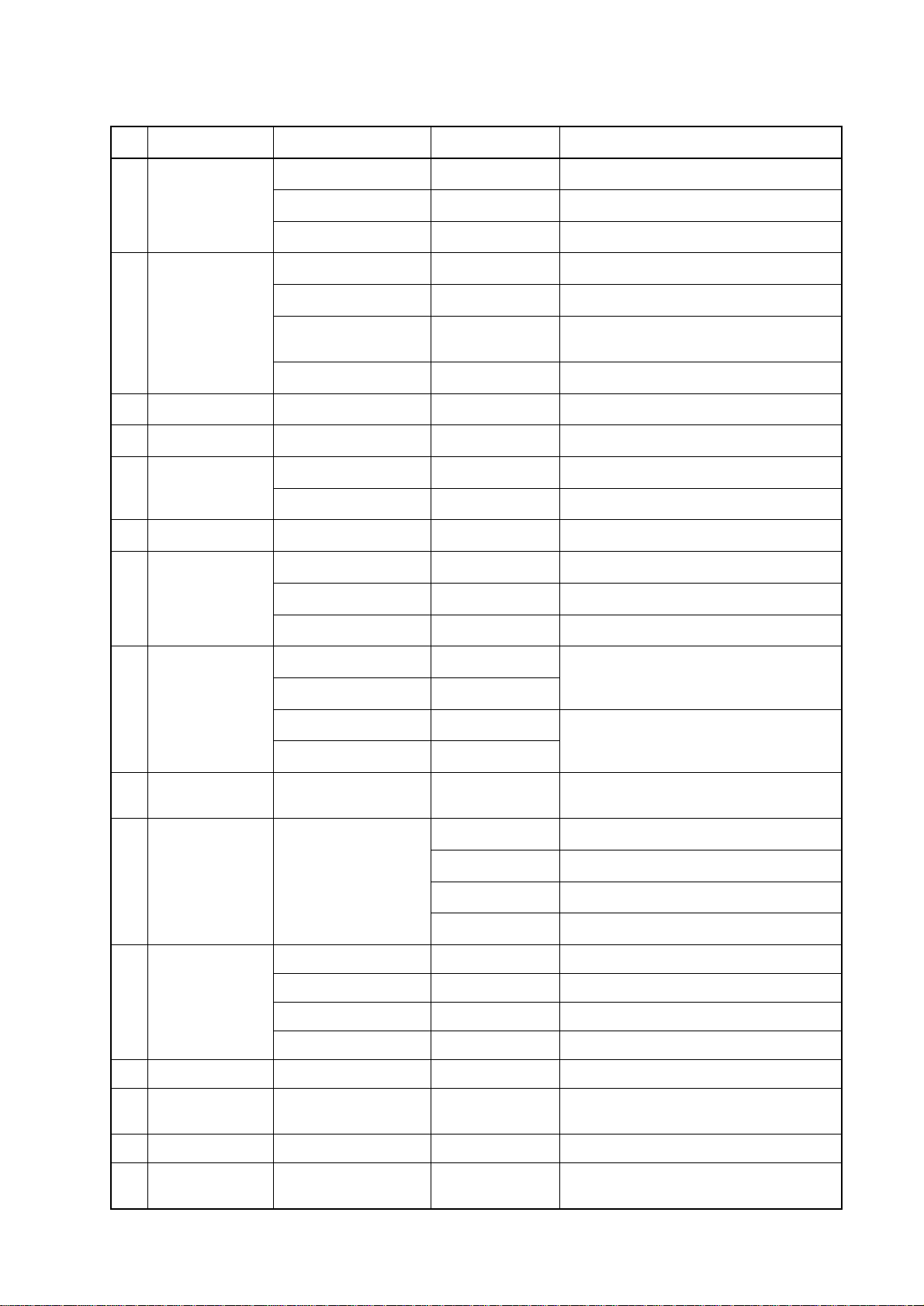
Optional equipment (con't)
.oNemaNepyT.oNedoCskrameR
S810-APG264-140-000FD0581-PGrof
9tinuannetnA
01recudsnarT
11yssaelbaC2904S20484-431-000noitcennocrecudsnartWk1rof
21xobgnihctaM0001-BM908-040-000noitcennocrecudsnartWk1rof
31rosnesTS
41StiklluhrennI033AQ-31.oN042-308-000tinuannetnagnitnuomrof
51
erutarepmeT
rosnes
610-APG635-140-000F0581-PGrof
S910-APG455-140-000FD0581-PGrof
DSP5-025521-510-000W006rof
DWP5-025621-510-000W006rof,tnuommosnartelbacm8/w
DSM5-025721-510-000
T1-002/05071-510-000Wk1rof
BSM20-TS689-731-000epytlluh-urhT
BSP20-TS789-731-000epytlluh-urht,elbacm8/w
BTM20-T620-040-000
BSM20-T040-040-000
BSM30-T720-040-000
,rotcennocfoorpretawdnaelbacm8/w
W006rof
DSM-TS425422-510-000
DSM-TS525362-510-000
61recudirT
DWP-TS025821-510-000
DWP-TS525162-510-000
71
81reifitceR26-RP
91.yssaelbaC
02annetnapihW2.1-WAF640-631-000FD0581-PGrof
12
retrevnoC
noitcennoc
etomeR
rellortnoc
7414S20280-141-000
484-310-000CAV001rof
584-310-000CAV011rof
684-310-000CAV022rof
784-310-000CAV032rof
050-1100FPS6A-JM442-231-000m5,P4-P6,radarnoitcennocrof
001-1100FPS6A-JM633-231-000m01,P4-P6,radarnoitcennocrof
050-2100FPS6A-JM424-431-000m5,P6-P6,S/Erodiavanrof
001-2100FPS6A-JM718-331-000m01,P6-P6,S/Erodiavanrof
E-F581-CMR023-573-400yrettab,revoclyniv,rellortnoC
W006rof
W006rof
22draCMAR400-CM20MAR00097-173-400BM2
32
nocaeBSPGD
revieceR
08-RG-F0581-PGrof
iii
Page 6
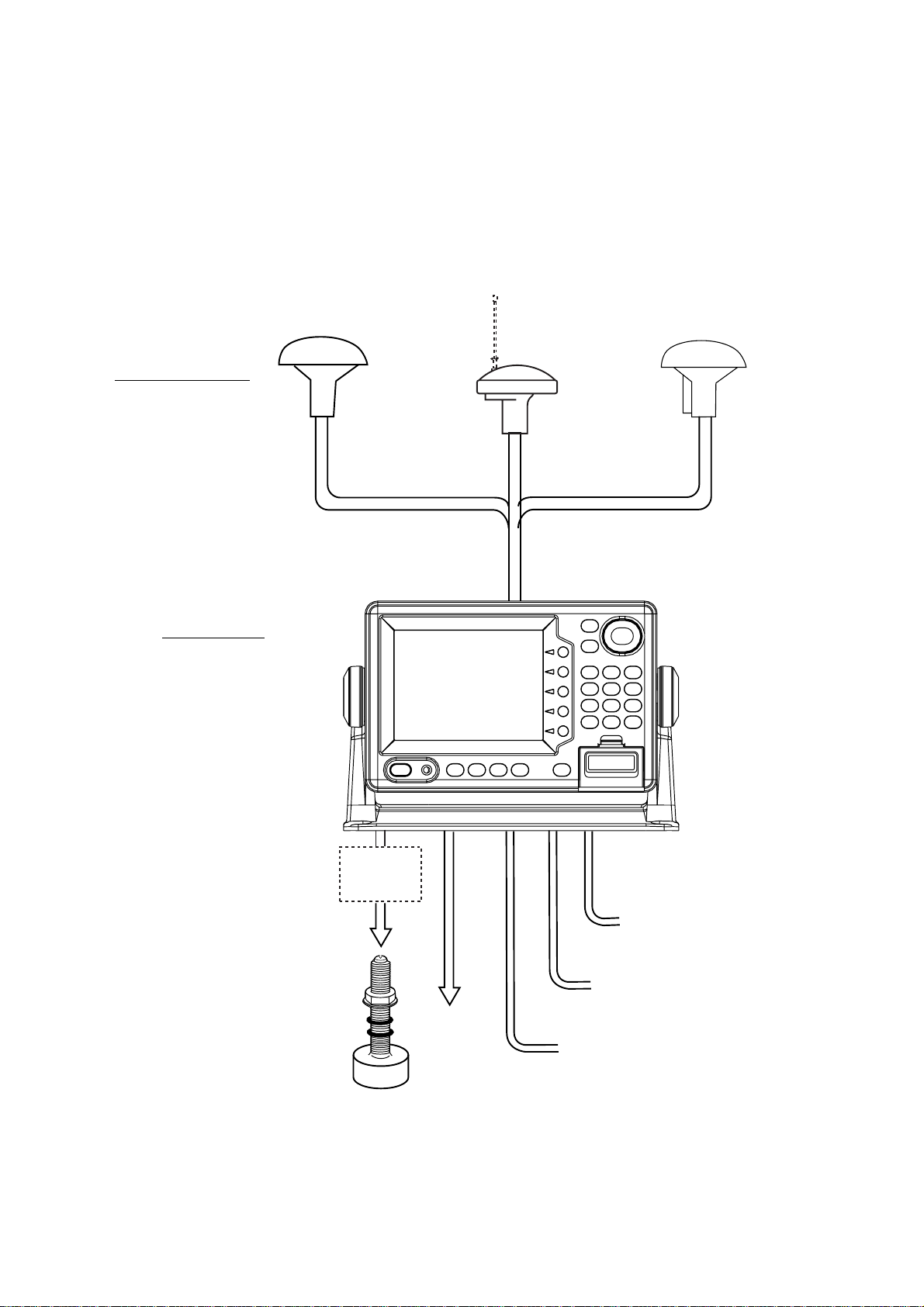
System Configuration
The GP-1850F/1850DF mainly consists of a display unit, a GPS antenna and a
dual frequency transducer. A DGPS beacon receiver is provided inside the display
unit for GP-1850DF type. The mini chart card drive in the display unit loads electronic charts. External equipment which can be connected include water temperature and speed sensors, autopilot, and DGPS beacon receiver (GP-1850F).
GPA-018
GPA-017
(for GP-1850F)
ANTENNA UNIT
Receives signal from
GPS satellite and beacon
reference station
(GP-1850DF only).
(for GP-1850DF)
1.2 m Whip antenna
(Option)
GPA-019
(for GP-1850DF)
DISPLAY UNIT
Ship’s position is
calculated in longitude
and latitude from signal
received from the antenna unit and displayed
on the screen.
*Matching
Box
MB-1000
Temp. sensor
(option)
Ship’s mains
10.8—31.2 VDC
External equipment
(Autopilot, etc.)
DGPS beacon receiver
GP-1850F only
Transducer
*Required for 1 kW transducer only
iv
Page 7
1. Installation of Standard Equipment
1.1 Installation of Display Unit
Mounting considerations
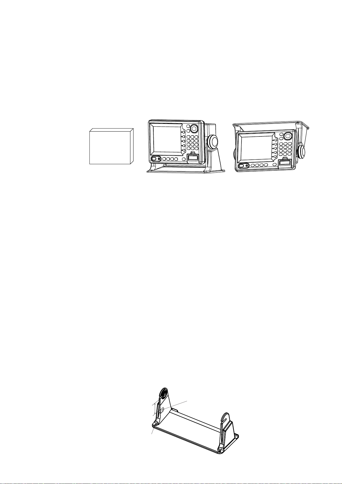
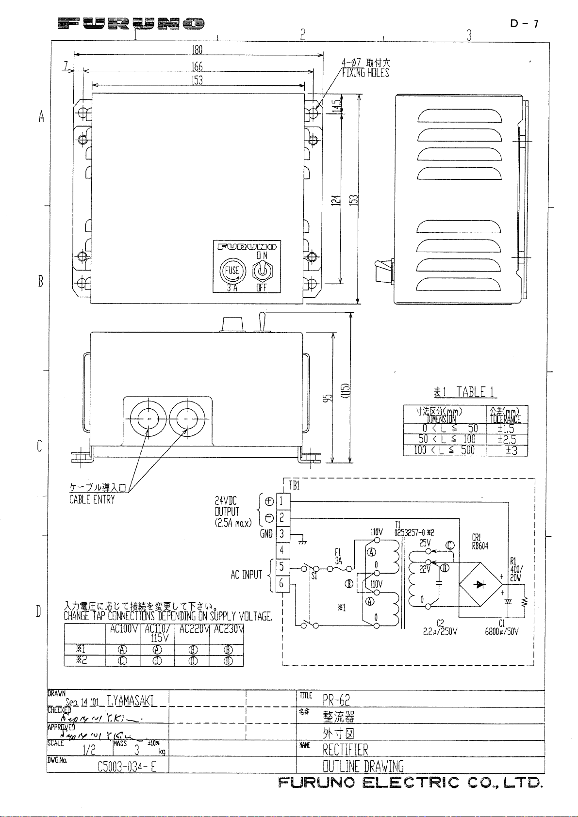
The display unit can be installed on a tabletop, on the overhead or flush mounted
in a console or panel.
Figure 1-1 Tabletop, overhead mounting methods
OverheadTabletopHard Cover
When selecting a mounting location for the display unit keep the following in mind:
• Keep the display unit out of direct sunlight.
• The temperature and humidity should be moderate and stable.
• Locate the unit away from exhaust pipes and vents.
• The mounting location should be well ventilated.
• Mount the unit where shock and vibration are minimal.
• Keep the unit away electromagnetic field generating equipment such as motor ,
generator .
• For maintenance and checking purposes, leave sufficient space at the sides
and rear of the unit and leave slack in cables.
• A magnetic compass will be affected if placed too close to the display unit.
Observe the following compass safe distances to prevent disturbance to the
magnetic compass:
Standard compass: 0.98 meters
Steering compass: 0.74 meters
• Rubber cushions which absorb vibration (supplied) may be attached as below
if vibration is a problem.
45±5mm
Aline with edge
of hanger.
Rubber cushion
TM-166 No.18 black
1-1
Page 8
Mounting procedure
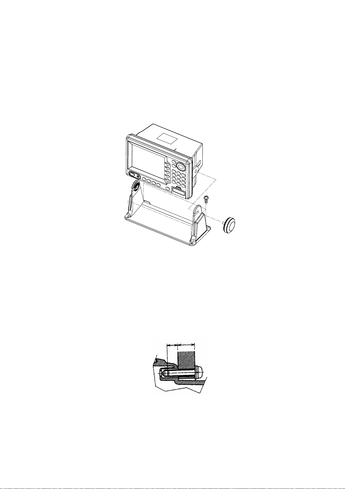
Follow the procedure below to mount the display unit on a tabletop or the overhead.
Tabletop, overhead mounting
1. Fix the hanger by four tapping screws M5 X 16.
2. Screw knob bolts in display unit, set it to hanger, and tighten knob bolts.
3. Attach hard cover to protect LCD.
WARNING
Figure 1-2 Tabletop, overhead mounting of display unit
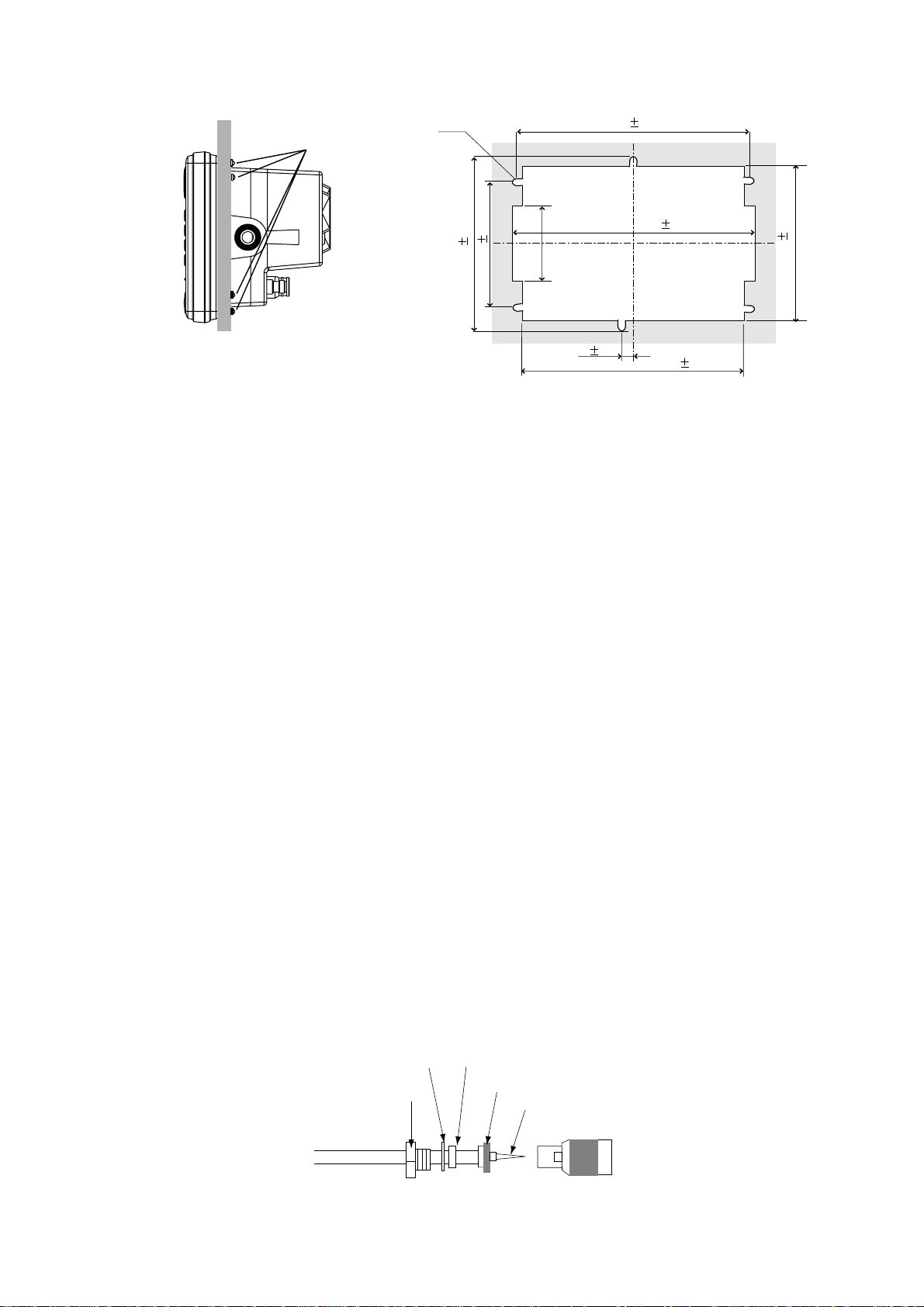
Flush mounting
Note:
11 to 14 mm. For bulkhead which exceeds 14 mm in thickness the length of the
pan head screws should be bulkhead thickness plus 7.3±1.5 mm. Also the length
of B below should max. 7 mm.
1. Prepare a cutout in the mounting location whose dimensions are as shown in
2. Fix the display unit by six pan head screws. Refer to the outline drawing on
Use supplied pan head screws when the thickness of the bulkhead is from
B
A
Figure 1-3.
page D-2.
1-2
Page 9
Pan head screws
6-R2.25
Cutout for flush mount
242 0.5
244 1
89 0.5
147 0.5
Flush mount
Figure 1-3 Flush mounting of display unit
1.2 Installation of Antenna Unit
Mounting considerations
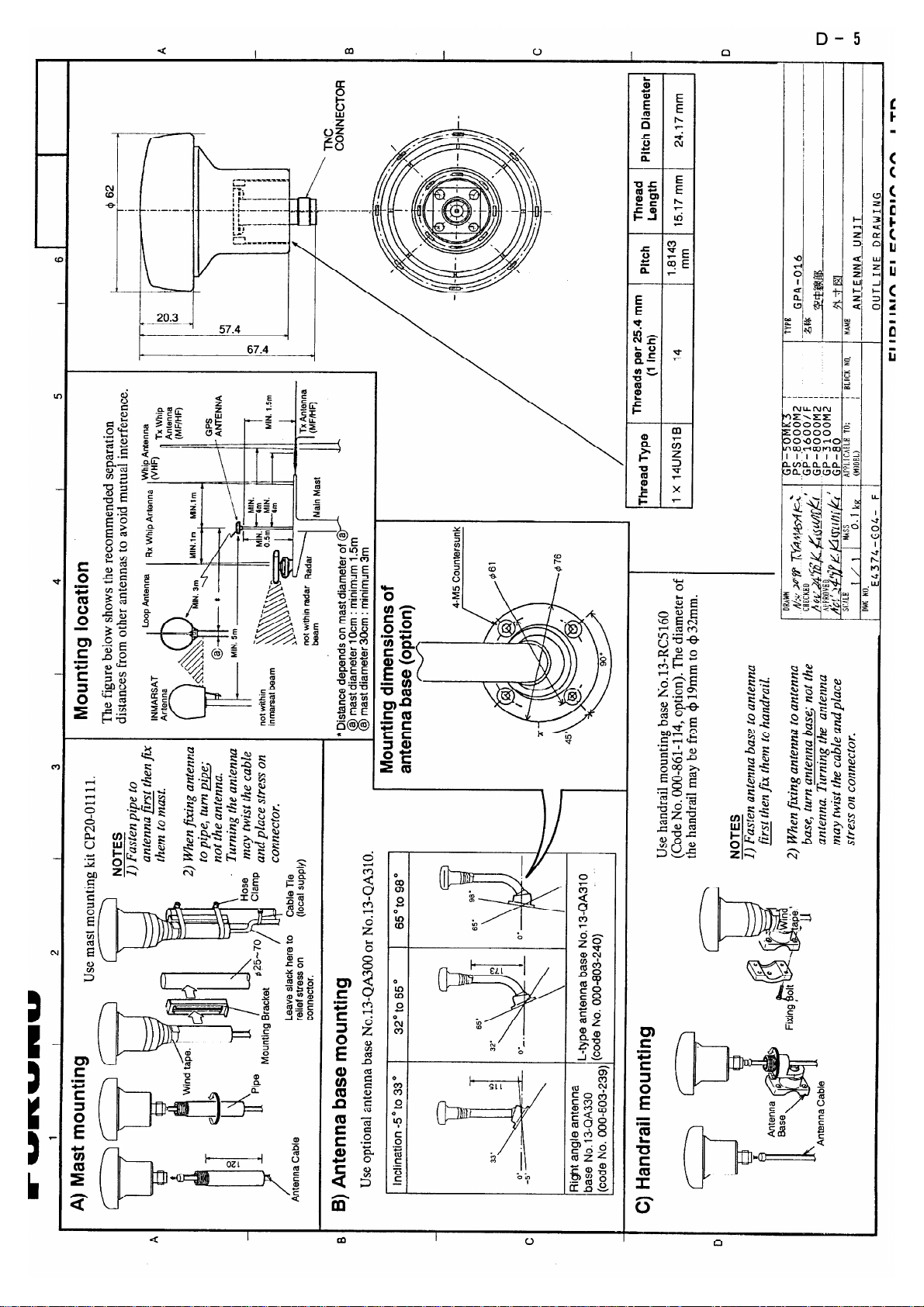
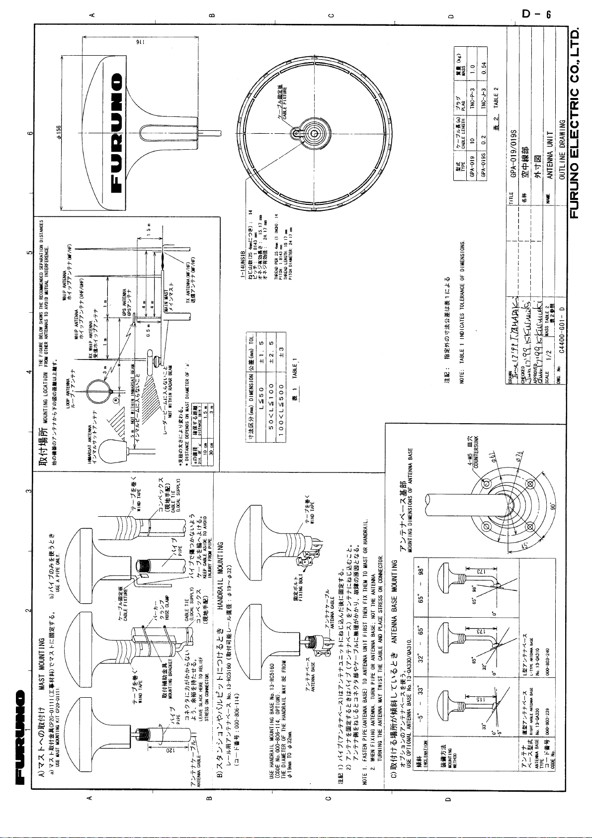
Install the antenna unit referring to the installation diagram on page D-3 or D-4.
When selecting a mounting location for the antenna unit, keep in mind the following points:
• Select a location out of the radar beam. The radar beam will obstruct or prevent
reception of the GPS satellite signal.
50
143 1
15 0.5
238 1
• The location should be well away from a VHF antenna. A GPS receiver is interfered by a harmonic wave of a VHF antenna.
• There should be no interfering object within the line-of-sight to the satellites.
Objects within line-of-sight to a satellite, for example, a mast, may block reception or prolong acquisition time.
• Mount the antenna unit as high as possible. Mounting the antenna unit as high
as possible keeps it free of interfering objects and water spray , which can interrupt reception of GPS satellite signal if the water freezes.
• The length of the whip antenna for the GP-1850DF should be no longer than
1.2 meter to prevent antenna damage. Do not use a 2.5 meter whip antenna.
• If the antenna cable is to be passed through a hole which is not large enough to
pass the connector, you may unfasten the connector with a needle nose pliers
and 3/8-inch open-end wrench. Refasten it as shown in Figure 1-4 after running the cable through the hole.
Washer
Clamp nut
Gasket (reddish brown)
Shield
Center pin (soldered)
Connector shell
Figure 1-4 How to assemble the connector
1-3
Page 10
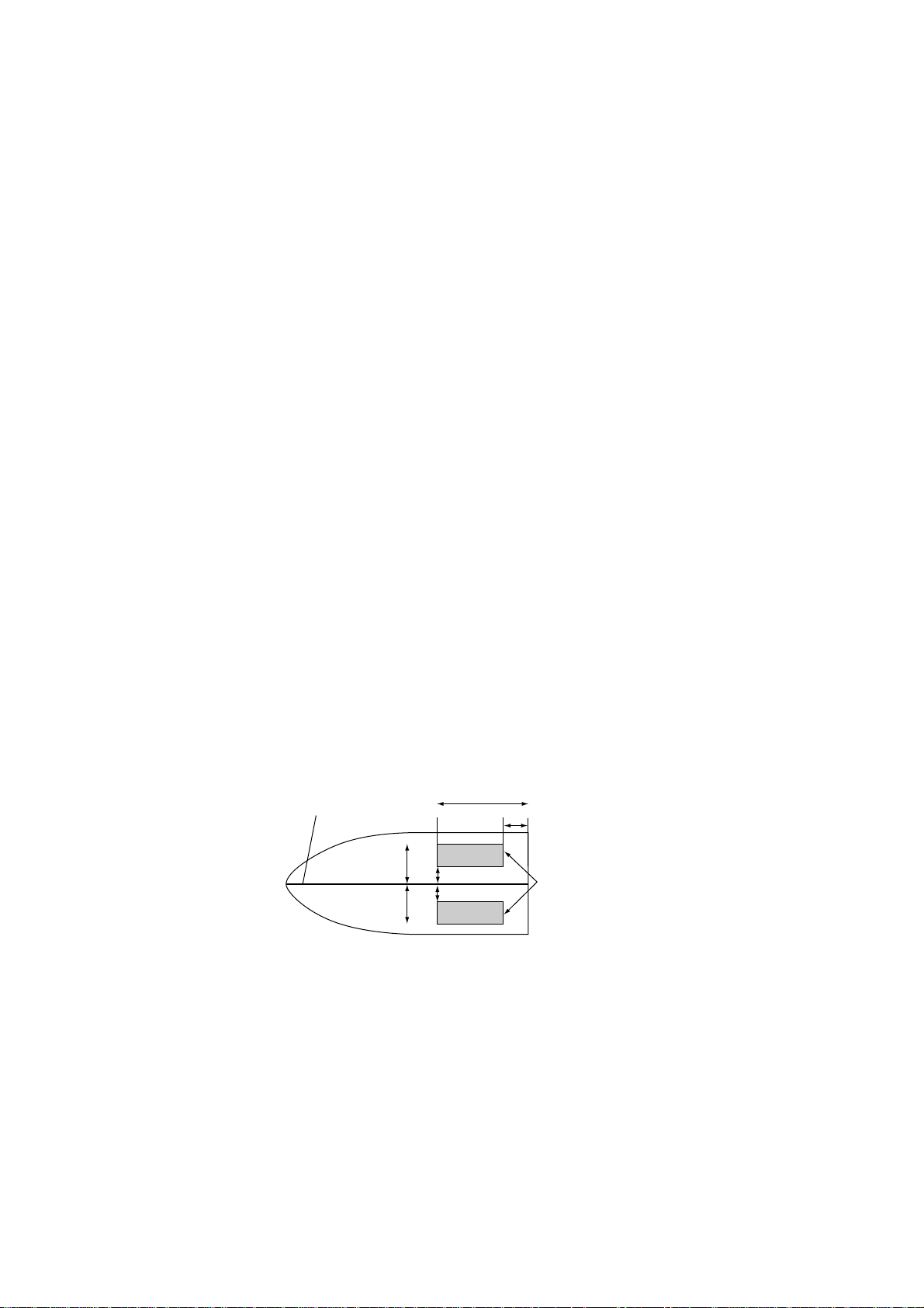
1.3 Installation of Transducers
Installing the inside-hull mount transducer
Necessary tools
You will need the following tools:
• Sandpaper (#100)
• Silicone sealant
Remarks on installation
• Do the installation with the boat hauled out of the water.
• Turn off the engine while installing the equipment.
• Install the transducer in the engine room.
Selecting the mounting location
Keep the following points in mind when selecting a mounting location:
• The mounting location should be where the hull is of single-hull thickness and
is void of air or flotation materials other than solid fiberglass between the transducer face and the water.
• Do not place the transducer over hull struts or ribes which run under the hull.
• Avoid a location where the rising angle of the hull exceeds 15°, to minimize the
effect of the boat’s rolling.
• You will finalize the mounting location through some trial and error . The procedure for this is shown later.
15cm
15cm
1/2
1/3
Mounting location
for transducer
Center line
50cm
50cm
Figure 1-5 Inside-hull transducer mounting location
1-4
Page 11
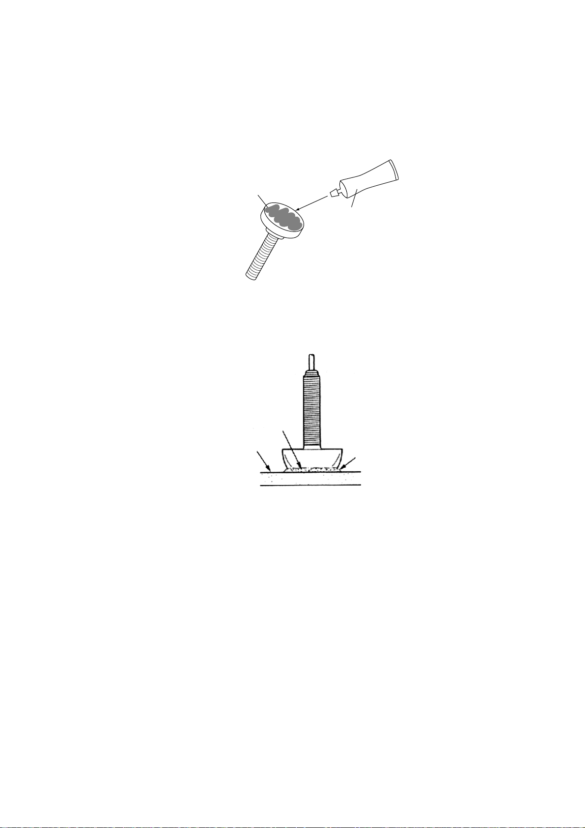
Attaching the transducer
1. Clean the transducer face to remove any foreign material. Lightly roughen the
transducer face with #100 sandpaper. Also, roughen the inside of the hull where
the transducer is to be mounted.
2. Warm the silicone sealant to 40°C before usage to soften it. Coat the transducer face and mounting location with silicone sealant.
Transducer face
Silicone sealant
Figure 1-6 Coating the transducer face with silicone sealant
3. Press the transducer firmly down on the hull and gently twist it back and forth to
remove any air which may be trapped in the silicone sealant.
Squeeze out
air bubbles.
Hull
Silicone
sealant
Figure 1-7 Attaching transducer to hull with silicone sealant
1-5
Page 12
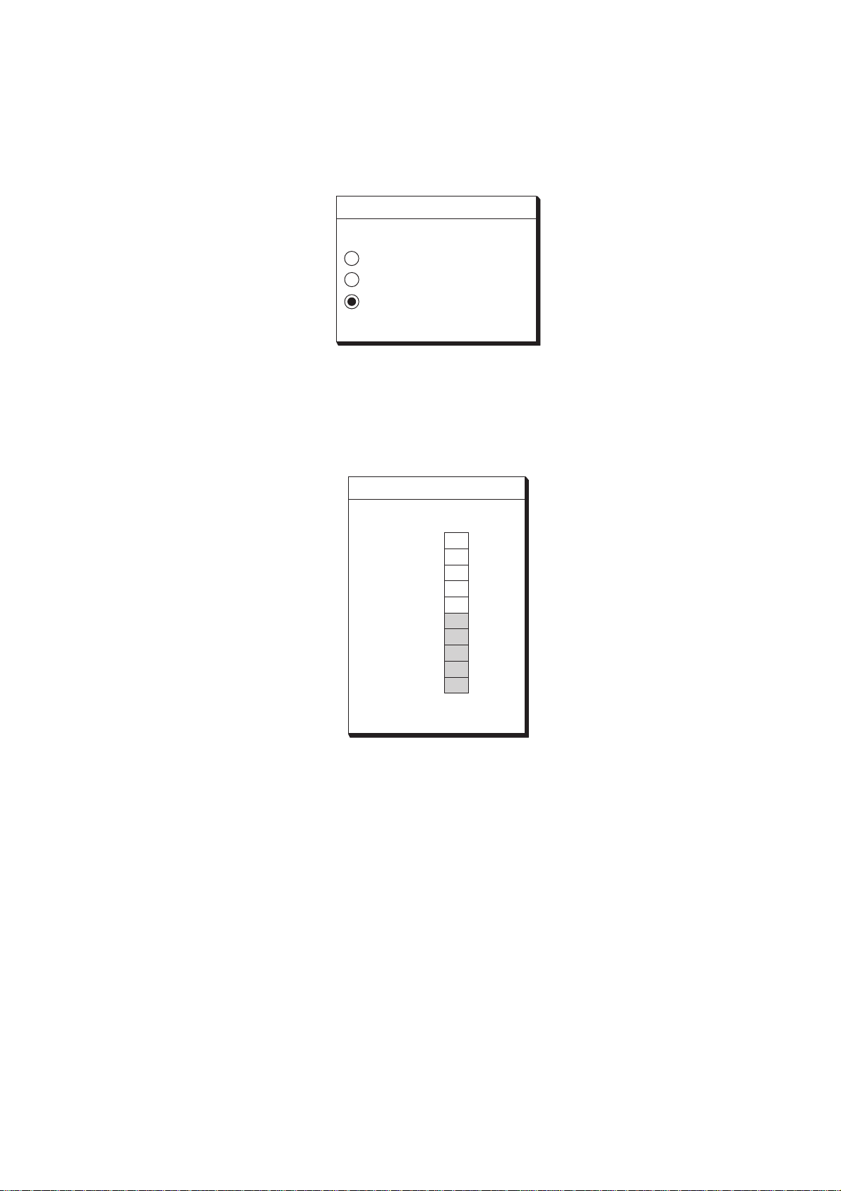
Observing the picture
1. Press the [POWER] key to turn on the display unit.
2. Press the [SNDR] key to select the sounder display.
3. Press the soft key labeled "MODE/FREQ" to display the following message.
MODE/FREQ
▲
AUTO CRUISING
AUTO FISHING
MANUAL
▼
Figure 1-8 MODE FREQ selection screen
4. Select "MANUAL" by the arrow key.
5. Press the soft key labeled "RETURN".
6. Press the soft key labeled "GAIN" to display the following message.
GAIN
▲
50
HIGH
LOW
▼
Figure 1-9 GAIN adjustment screen
7. Confirm that Gain is set at 50 (midpoint).
8. Press the soft key labeled "RETURN".
9. Press the soft key labeled "RANGE".
10.Select "15ft" by the [▲] key.
11.Note the depth to the seabed.
1-6
Page 13
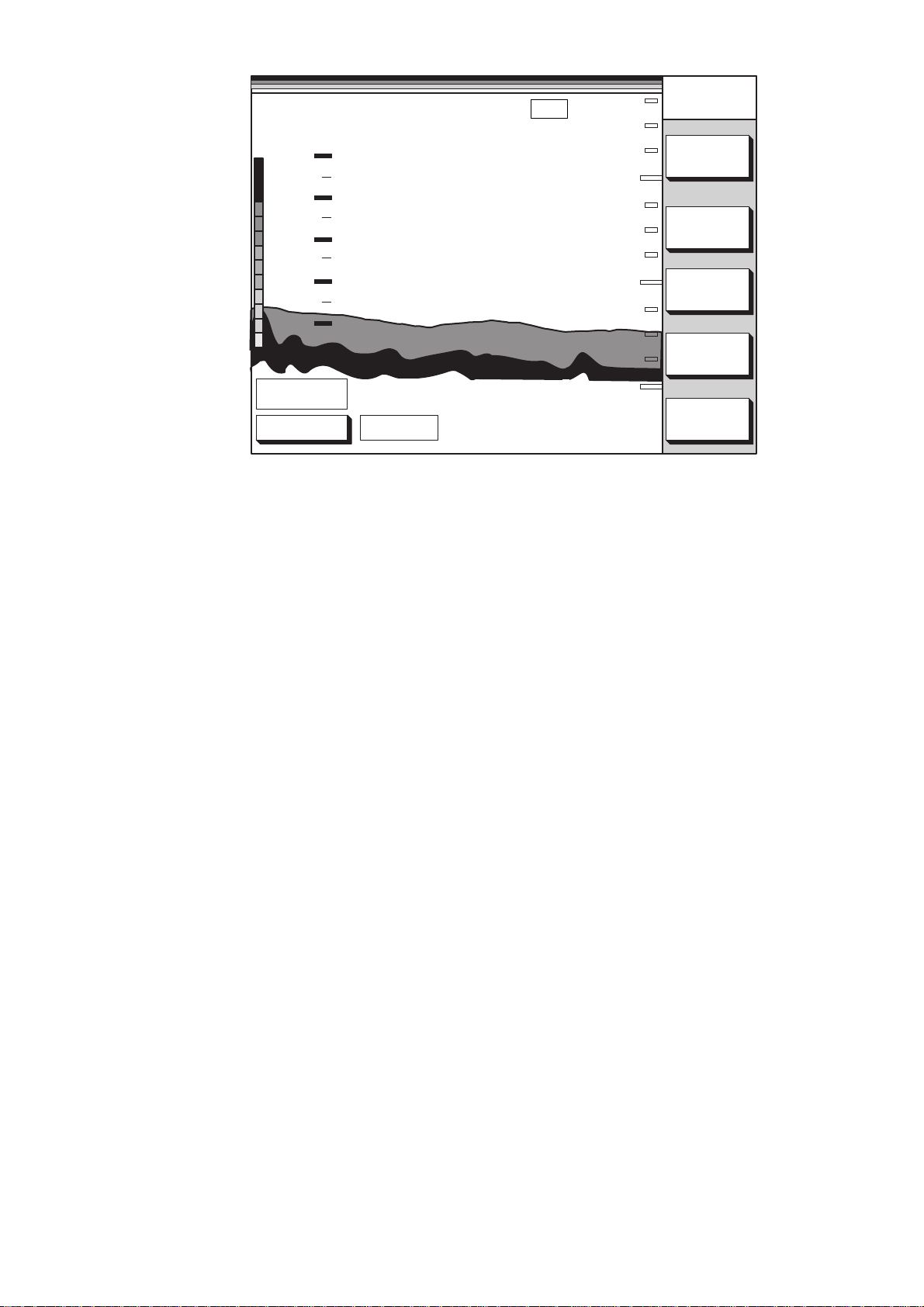
°C
30
20
0.0
SOUNDER
RANGE
5
10
0
32.8
10
15
DGPS 3D 50kHz
Figure 1-10 Video sounder picture
If the bottom is displayed in red and the light-blue color appears the mounting
location is suitable. You can leave the transducer in position.
If the bottom is not displayed in reddish brown, the mounting location is unsuitable. Relocate the transducer and do the following.
1. Press the [POWER] key to turn off the power.
2. Gently dismount the transducer with piece of wood.
3. Do steps 1 through 5 in the previous procedure. Repeat
until a suitable location is found.
GAIN
SHIFT
MODE/
FREQ
SNDR
FUNC
Final preparation
Support the transducer with a piece of wood to keep it in place wile it is drying. Let
the transducer dry 24–72 hours.
1-7
Page 14
Installing the thru-hull mount transducer
Transducer mounting location
This type of mounting provides the best performance of all, since the transducer
protrudes from the hull and the effect of air bubbles and turbulence neat the hull
skin is reduced. When the boat has a keel, the transducer should be at least 30 cm
away from it. Typical through hull mountings are shown in the figure on the next
page.
The performance of the video sounder is directly related to the mounting location
of the transducer, especially for high-speed cruising. The installation should be
planned in advance, keeping the standard cable length (8 m) and the following
factors in mind:
• Air bubbles and turbulence caused by movement of the boat seriously degrade
the sounding capability of the transducer . The transducer should, therefore, be
located in a position where water flow is the smoothest. Noise from the propellers also adversely affects performance and the transducer should not be
mounted nearby. The lifting strakes are notorious for creating acoustic noise,
and these must be avoided by keeping the transducer inboard of them.
• The transducer must always remain submerged, even when the boat is rolling,
pitching or up on a plane at high speed.
• A practical choice would be somewhere between 1/3 and 1/2 of the boat's length
from the stern. For planing hulls, a practical location is generally rather far astern,
so that the transducer is always in water regardless of the planing attitude.
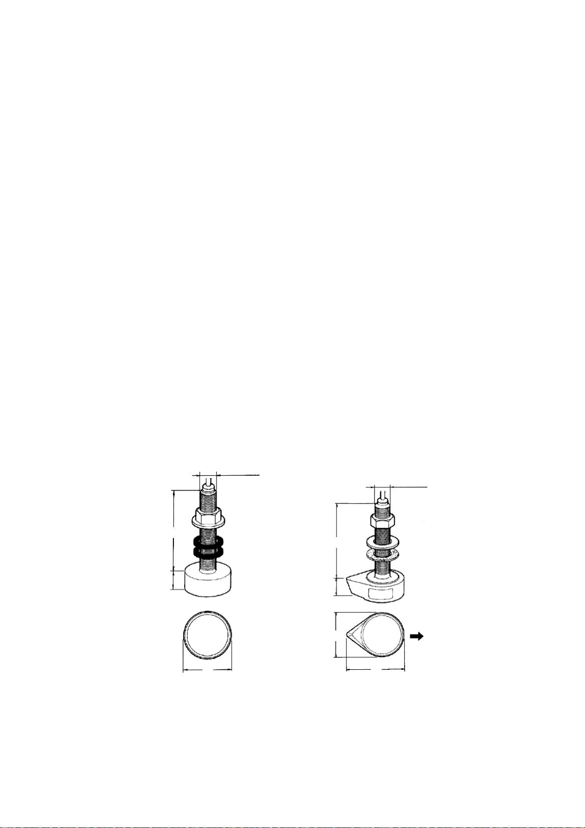
Transducer outline drawings
30
120
22
All dimensions
in millimeters
120
28
68
24
Ship's
bow
68 87
520-5PSD (option) 520-5MSD (option)
Figure 1-11 Transducer outline drawings
1-8
Page 15
Acceptable transducer mounting locations
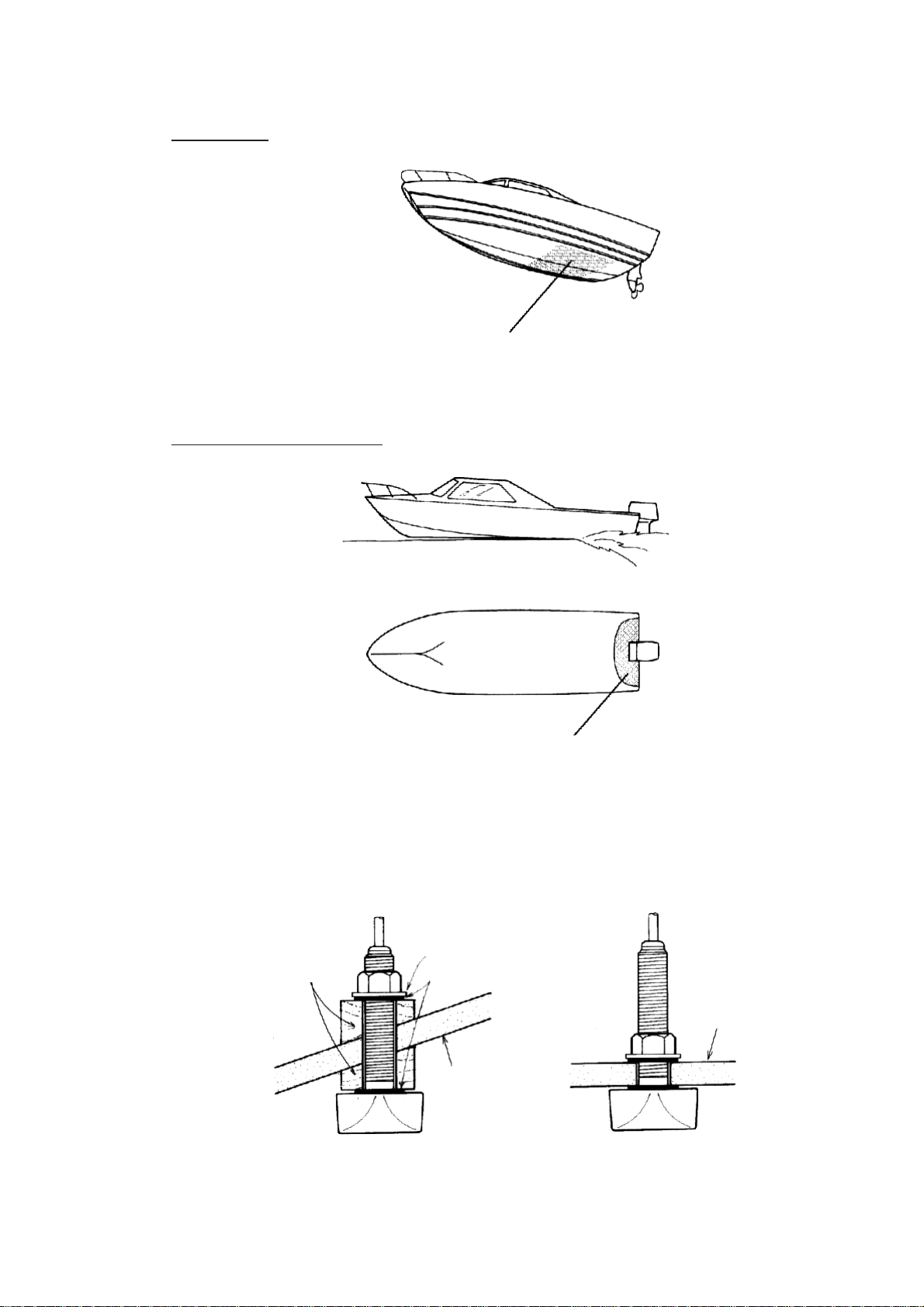
• Position 1/2 to 1/3 length of the hull from stern
• 15 to 30 cm off center line (inside first lifting strakes).
• Within the wetted bottom area
• Deadrise angle within 15°
Deep-V hull
Figure 1-12 Transducer mounting location on deep-V hull
High speed V-planing hull
Figure 1-13 Transducer mounting location on high speed
V-planing hull
Typical through-hull mount transducer installations
Flat washer
Fairing block
Rubber washer
Hull
bottom
Deep-V Hull Flat Hull
Figure 1-14 Typical through-hull mount transducer installations
Hull
bottom
1-9
Page 16
Procedure for installing the thru-hull mount transducer
W
1. With the boat hauled out of the water , mark the location selected for mounting
the transducer on the bottom of the hull.
2. If the hull is not level within 15° in any direction, fairing blocks made out of teak
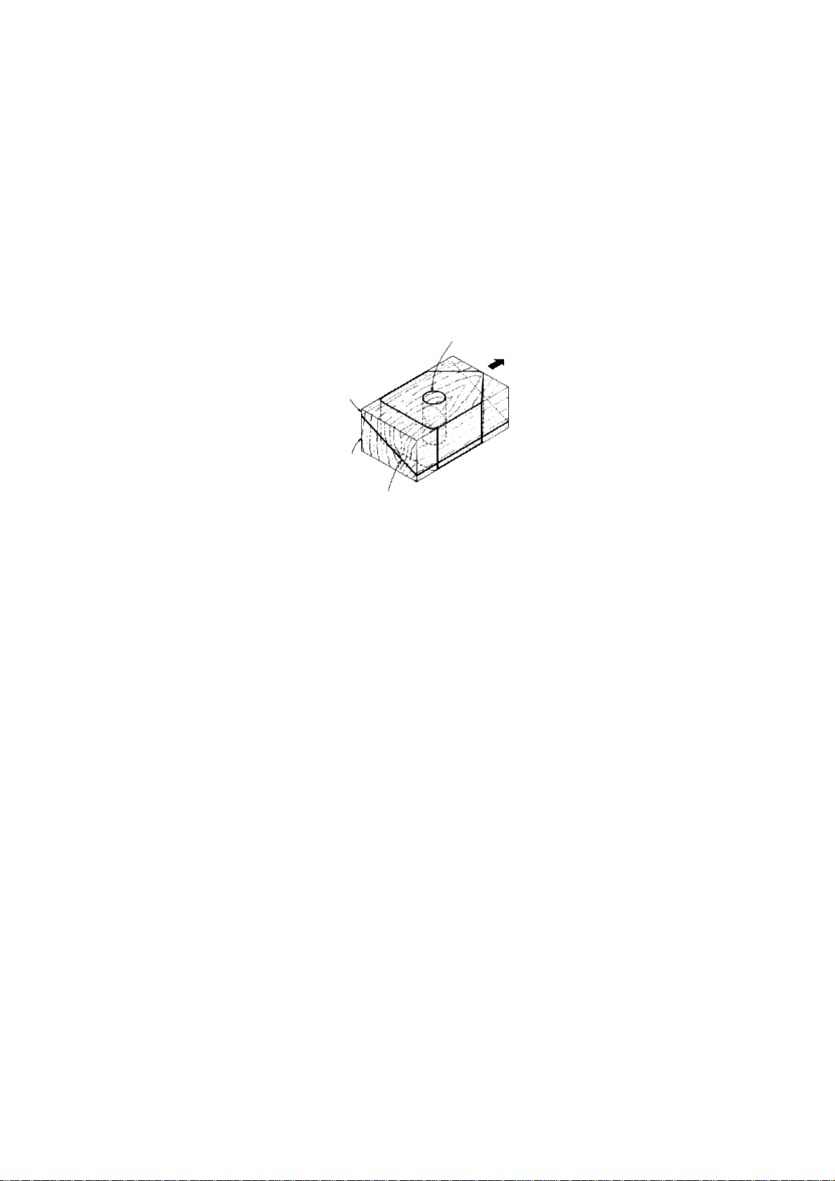
should be used between the transducer and hull, both inside and outside, to
keep the transducer face parallel with the water line. Fabricate the fairing block
as shown below and make the entire surface as smooth as possible to provide
an undisturbed flow of water around the transducer. The fairing block should be
smaller than the transducer itself to provide a channel to divert turbulent water
around the sides of the transducer rather than over its face.
Hole for
stuffing tube
Upper
half
Lower
half
Saw along slope of hull.
BO
Figure 1-15 Construction of fairing block
3. Drill a hole just large enough to pass the threaded stuffing tube of the transducer through the hull, making sure it is drilled vertically.
4. Apply a sufficient amount of high quality caulking compound to the top surface
of the transducer , around the threads of the stuffing tube and inside the mounting hole (and fairing blocks if used) to ensure watertight mounting.
5. Mount the transducer and fairing blocks and tighten the locking nuts. Be sure
that the transducer is properly oriented and its working face is parallel to the
waterline.
Note:
Do not over-stress the stuffing tube and locking nuts through excessive tightening, since the wood block will swell when the boat is placed in the water. It is
suggested that the nut be tightened lightly at installation and retightened several
days after the boat has been launched.
1-10
Page 17
Installing the transom mount transducer
This type of mounting is very commonly employed, usually on relatively small I/O
or outboard boats. Do not use this method on an inboard motor boat because
turbulence is created by the propeller ahead of the transducer.
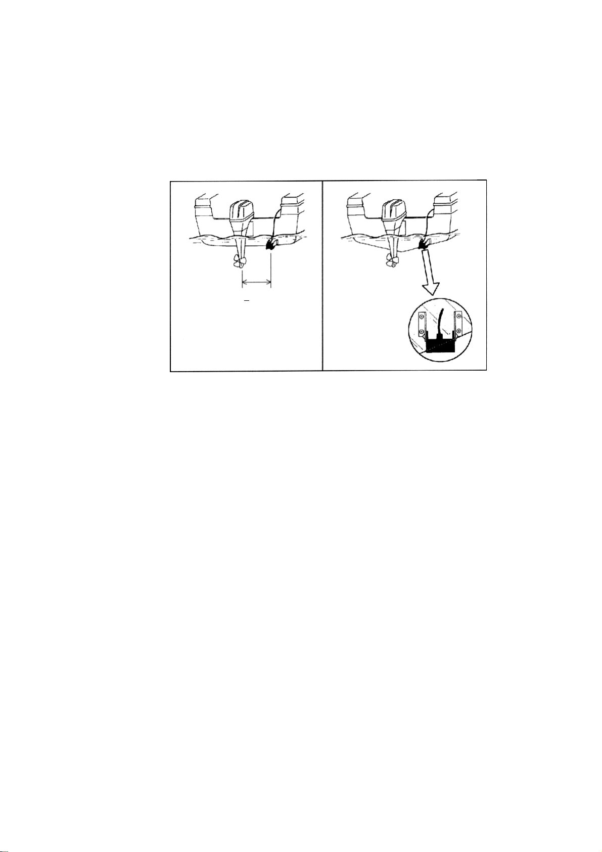
There are two methods of installation: flush with hull (for flat hulls) and projecting
from hull (for deep V-hulls).
D
D>
50 cm
Flat Hull Deep V-hull
Figure 1-16 Transom mount transducer mounting locations
Installing the transom mount transducer flush with hull
(for flat hulls)
A suitable mounting location is at least 50 cm away from the engine and where the
water flow is smooth.
1. Drill four pilot holes in the mounting location.
2. Attach the transducer to the bracket with tapping screws (supplied).
3. Adjust the transducer position so the transducer faces right to the seabed.
Note:
If necessary, to improve water flow and minimize air
bubbles staying on the transducer face, incline the transducer about 5° at the rear. This may require a certain amount
of experimentation for fine tuning at high cruising speeds.
4. Fill the gap between the wedge front of the transducer and transom with epoxy
material to eliminate any air spaces.
1-11
Page 18
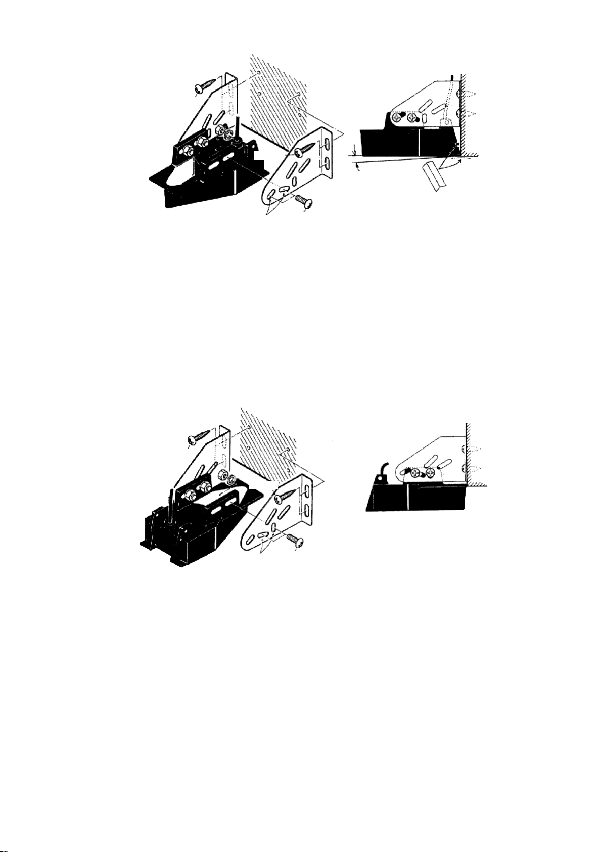
M5 x 20
M5 x 20
5°
Tape
No. 1
M5 x 14
Figure 1-17 Transom mount transducer, mounting flush with hull
Installing the transom mount transducer projecting from hull
(for deep-V hulls)
This method is employed on deep-V hulls and provides good performance because the effects of air bubbles are minimal. Install the transducer parallel with
water surface; not flush with hull. If the boat is placed on a trailer care must be
taken not to damage the transducer when the boat is hauled out of the water and
put on the trailer.
M5 x 20
M5 x 20
No. 2
M5 x 14
Figure 1-18 Transom mount transducer, projecting from hull
T ransducer preparation
Before putting the boat in water, wipe the face of the transducer thoroughly with a
detergent liquid soap. This will lessen the time necessary for the transducer to
have good contact with the water. Otherwise the time required for complete "saturation" will be lengthened and performance will be reduced.
Do not paint the transducer. Performance will be affected.
1-12
Page 19
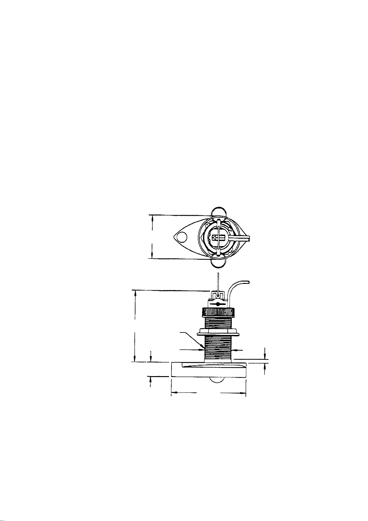
Triducer 524ST -MSD, 525ST-MSD
The triducer is designed for thru-hull mounting.
Mounting considerations
When selecting a mounting location keep the following points in mind:
• Air bubbles and turbulence caused by movement of the boat seriously degrade
the sounding capability of the transducer. The transducer should, therefore, be
located in a position where water flow is the smoothest. Noise from the propellers also adversely affects performance and the transducer should not be
mounted nearby. The lifting strakes are notorious for creating acoustic noise,
and these must be avoided by keeping the transducer inboard of them.
• The transducer must always remain submerged, even when the boat is rolling,
pitching or up on a plane at high speed.
• A practical choice would be somewhere between 1/3 and 1/2 of the boat’ s length
from the stern. For planing hulls, a practical location is generally rather far astern,
so that the transducer is always in water regardless of the planing attitude.
∅79 mm
133 mm
2.00"-12 UN
threads
∅51 mm
27 mm
140 mm
7 mm
Figure 1-19 Dimensions of triducer 524ST-MSD/525ST-MSD
1-13
Page 20
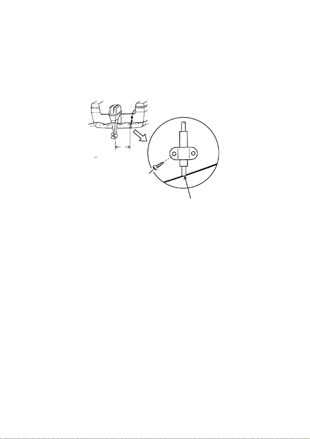
1.4 Installation of Sensors
Transom mount water temperature sensor
T-02MTB
• Fix the cable at a convenient location with cable clamp.
• When the cable is led in through the transom board, make a hole of approx. 17
mm diameter to pass the connector . After passing the cable, fill the hole with a
sealing compound.
D
D>50 cm
M5 x 20
Mount sensor
flush with hull bottom.
Figure 1-20 How to install transom mount water temperature sensor T-02MTB
1-14
Page 21
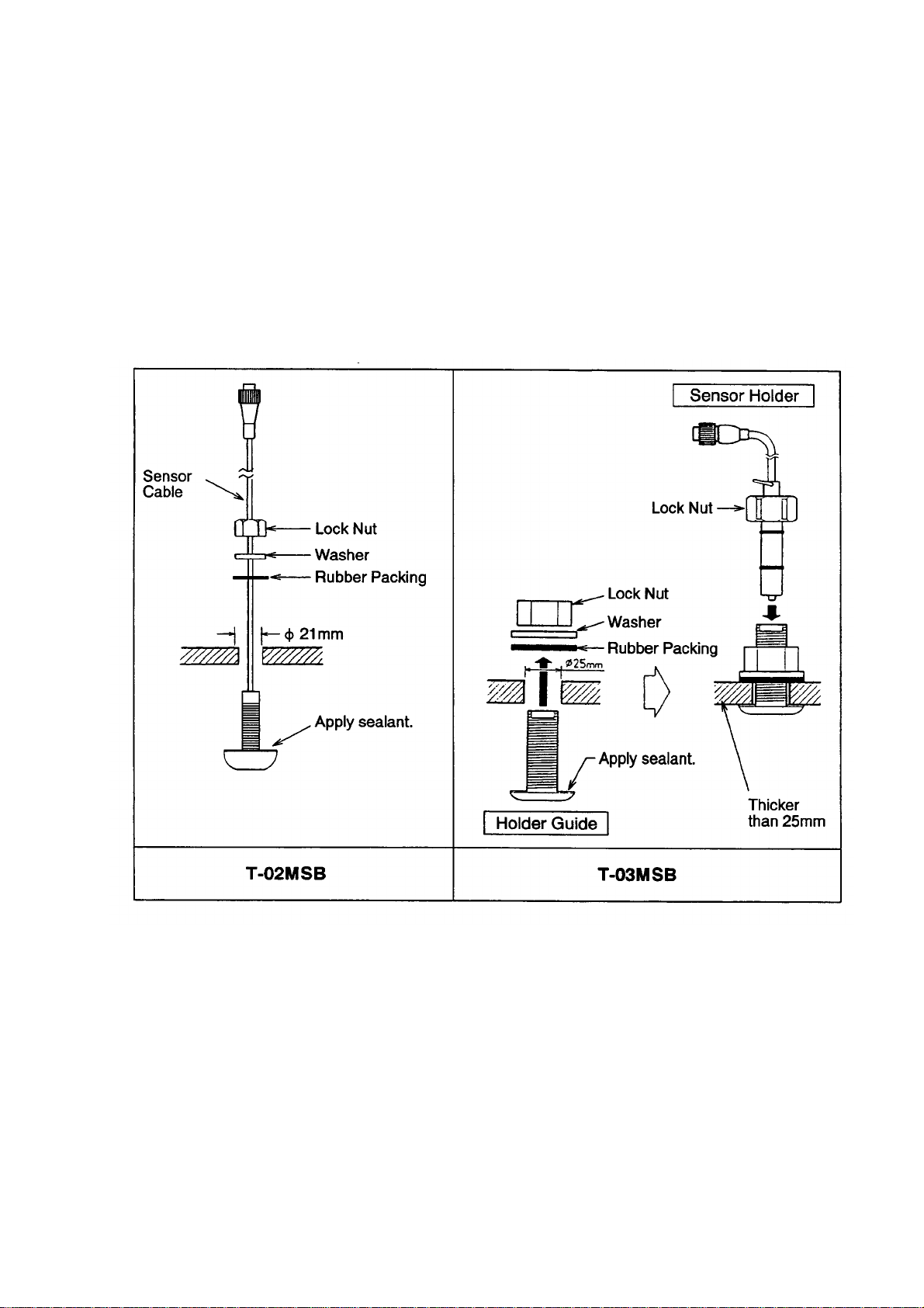
Thru-hull mount water temperature sensor
T-02MSB, T-03MSB
• Select a mid-boat flat position. The sensor does not have to be installed perfectly perpendicular. The sensor must not be damaged in dry-docking operation.
• Select a place apart from equipment generating heat.
• Select a place in the forward direction viewing from the drain hole, to allow for
circulation of cooling water.
• Select a place free from vibration.
Mount the sensor as shown below.
Figure 1-21 Thru-hull mount water temperature sensors
T-02MSB, T-03MSB
1-15
Page 22
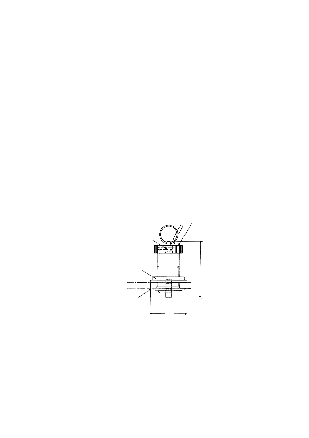
Through-hull mount water temperature/speed sensor
ST-02MSB, ST-02PSB
Select a suitable mounting location considering the following:
• Select a mid-boat flat position. The sensor does not have to be installed perfectly perpendicular. The sensor must not be damaged in dry-docking operation.
• Select a place apart from equipment generating heat.
• Select a place in the forward direction viewing from the drain hole, to allow for
circulation of cooling water.
• Select a place free from vibration.
1. Dry-dock the boat.
2. Make a hole of approx. 51 mm diameter.
3. Unfasten locknut and remove the sensor section.
4. Apply high-grade sealant to the flange of the sensor.
5. Pass the sensor casing through the hole.
6. Face the notch on the sensor toward boat’s bow and tighten the flange.
7. Set the sensor section to the sensor casing and tighten the locknut.
8. Launch the boat and check for water leakage around the sensor.
Locknut
Face "notch"
toward bow.
Flange nut
Coat with
silicone sealant.
51
Brim
ø77
123
Figure 1-22 Water temperature/speed sensor ST-02MSB,
ST-02PSB
1-16
Page 23
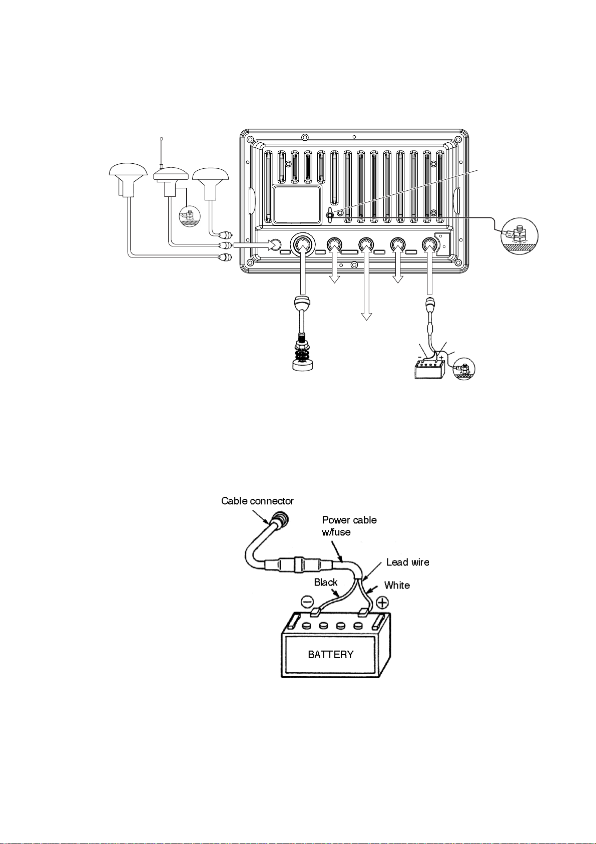
2. Wiring
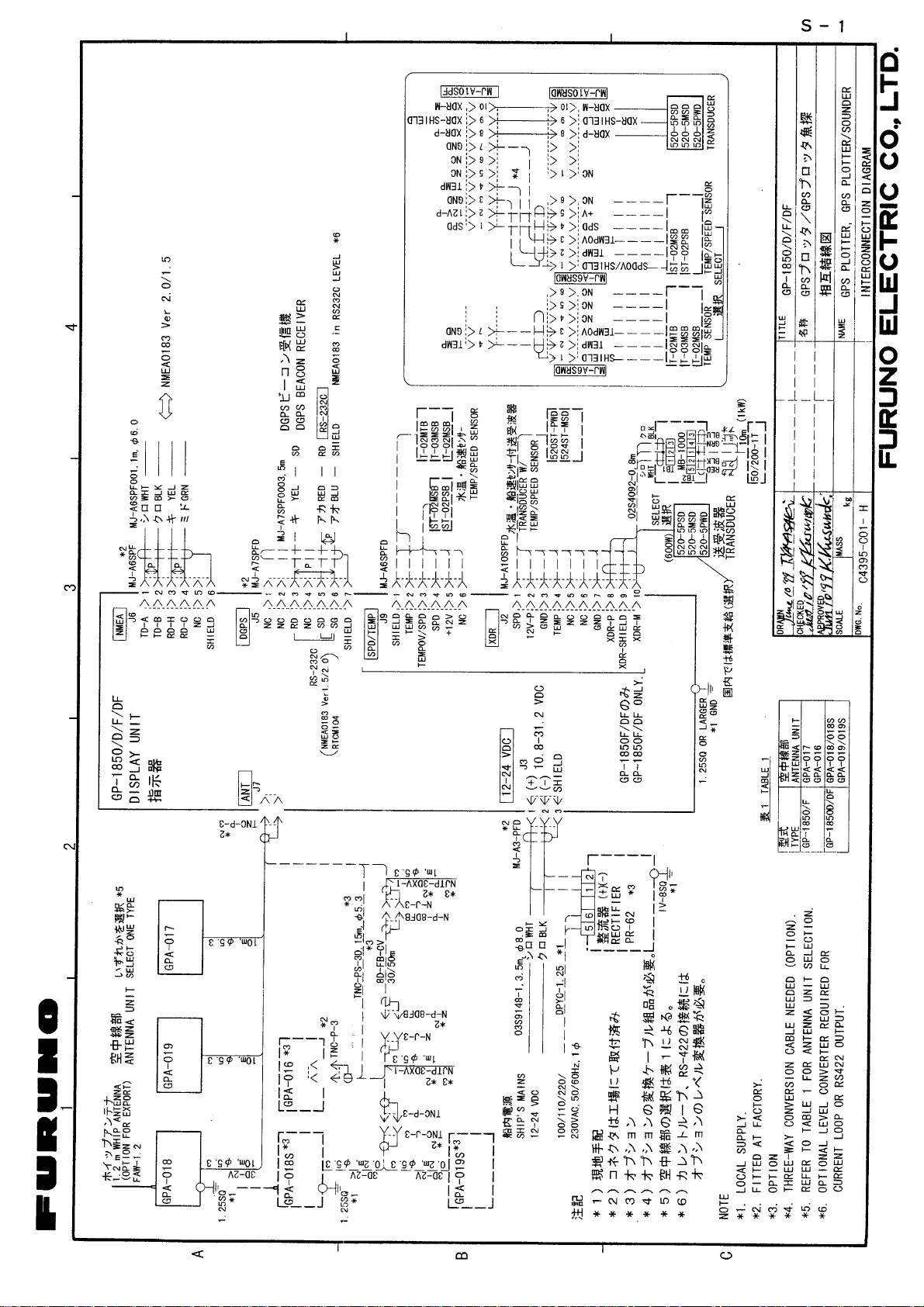
All wiring are terminated at the rear of the display unit.
GPA-019
(GP-1850DFj
Antenna unit
GPA-018
iGP-1850DFj
GPA-017
iGP-1850Fj
Ground
Display unit (back)
ANT XDR
Temperature
TEMP/SPD
Speed/
(Option)
DGPS beacon receiver
(option for GP-1850F,
RS-232C only)
DGPS
External
equipment
Transducer
Figure 2-1 Display unit, rear view
NMEA
Black
+ GND
1 3
2
-
12 - 24
VDC
White
Earth terminal
Ground
Shield
Power cable
Connect the power cable to the power connector. Connect the leads to the battery
(12 or 24 VDC); white to plus(+) terminal and black to minus(-) terminal.
(5 A)
Figure 2-2 Connecting the power cable to the battery
2-1
Page 24
Antenna unit
Connect the antenna cable to the ANT connector.
T ransducer
Connect the transducer cable to the XDR connector.
Water temperature/speed sensor
Connect the water temperature sensor (option) or water temperature/speed sensor (option) to the TEMP/SPD connector.
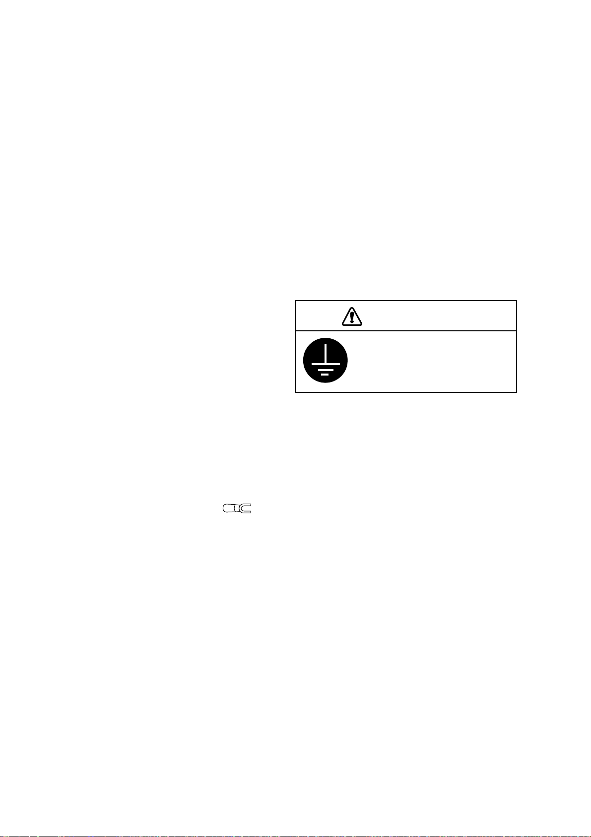
Ground
The display unit contains several
CPUs. While they are operating, they
radiate noise, which can interfere with
radio equipment. Ground the unit to
prevent interference. The grounding
wire should be 1.25 sq or larger and
as short as possible. Connect the
grounding wire to ship's ground. On a
fiberglass boat, it is best to install a ground plate that measures about 20 cm by 30
cm on the outside of the hull bottom to provide a ground point. If this is not practical, the engine block can be used.
CAUTION
Ground the equipment to
prevent electrical shock
and mutual interference.
Also, the antenna unit GPA-018S (option) should be grounded.
Note:
use an “open-type” lug ( ).
Use a “closed” lug to make the ground connection at the display unit. Do not
2-2
Page 25
Extending antenna cable length
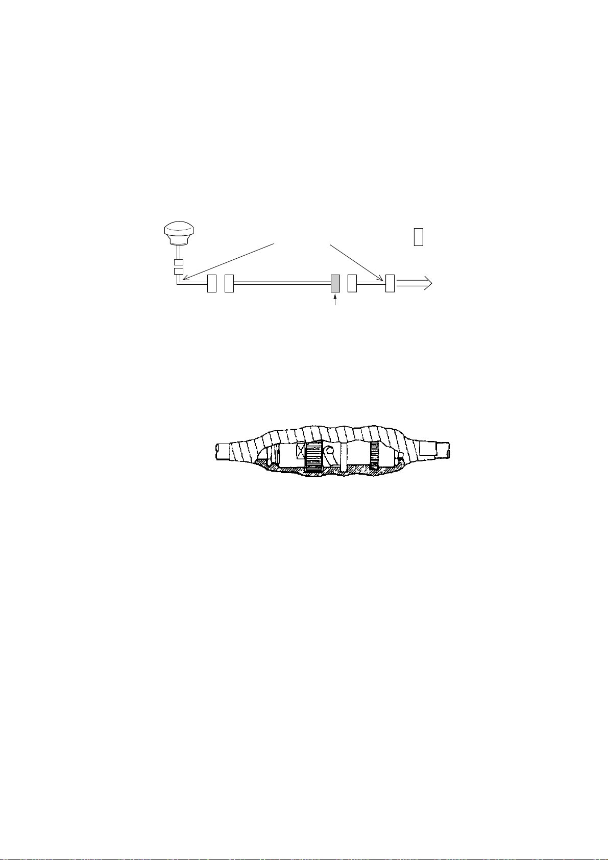
The standard cable is 10m long. For extension, in case of the GPA-016, GP A-018
and GP A-018S, an antenna cable set of 15m (GPA-018S and GPA-019S), 30m or
50m is available. Extension cable cannot be used with the GPA-017 or GP A-018.
◆ Extension cable line-up (in case of 30 m or 50 m)
Fabricate the end of the antenna cable and attach the coaxial connector. De-
tails are shown on next page.
Antenna Unit
GPA-016
GPA-018S
GPA-019S
Conversion
Cable Assy.
: Connector
1 m
Antenna Cable
30 m or 50 m 1 m
Fabricate locally. (See next page.)
To display unit
Figure 2-3 Cable extension
◆ Waterproofing connector
Wrap connector with vulcanizing tape and then vinyl tape. Bind the tape end
with cable-tie.
Figure 2-4 Waterproofing connector
2-3
Page 26
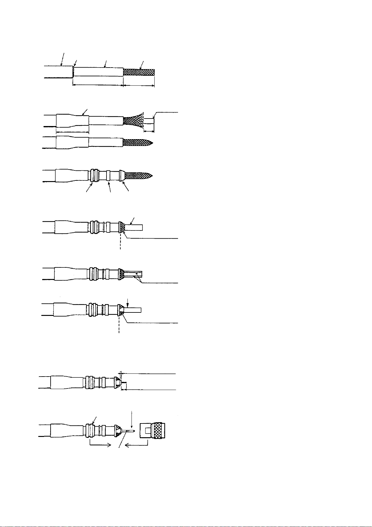
How to attach the N-P-8DFB connector
Outer Sheath
Cover with heat-shrink tubing and heat.
Armor
30
Clamp
Nut
Dimensions in millimeters.
Inner Sheath Shield
50
Gasket
(reddish
brown)
30
10
Clamp
Aluminum Foil
Remove outer sheath and armor by the dimensions
shown left.
Expose inner sheath and shield by the dimensions
shown left.
Cut off insulator and core by 10mm.
Twist shield end.
Ship on clamp nut, gasket and clamp as shown left.
Trim shield here.
Trim aluminum
tape foil here.
Clamp Nut
Insulator
1
5
Pin
Shell
Fold back shield over clamp and trim.
Cut aluminum foil at four places, 90° from one
another.
Fold back aluminum foil onto shield and trim.
Expose the insulator by 1mm.
Expose the core by 5mm.
Slip the pin onto the conductor. Solder them together
through the hole on the pin.
Insert the pin into the shell. Screw the clamp nut into
the shell.
Solder through
the hole.
(Tighten by turning the clamp nut. Do not tighten by
turning the shell.)
Figure 2-5 Fabrication of coaxial cable
2-4
Page 27
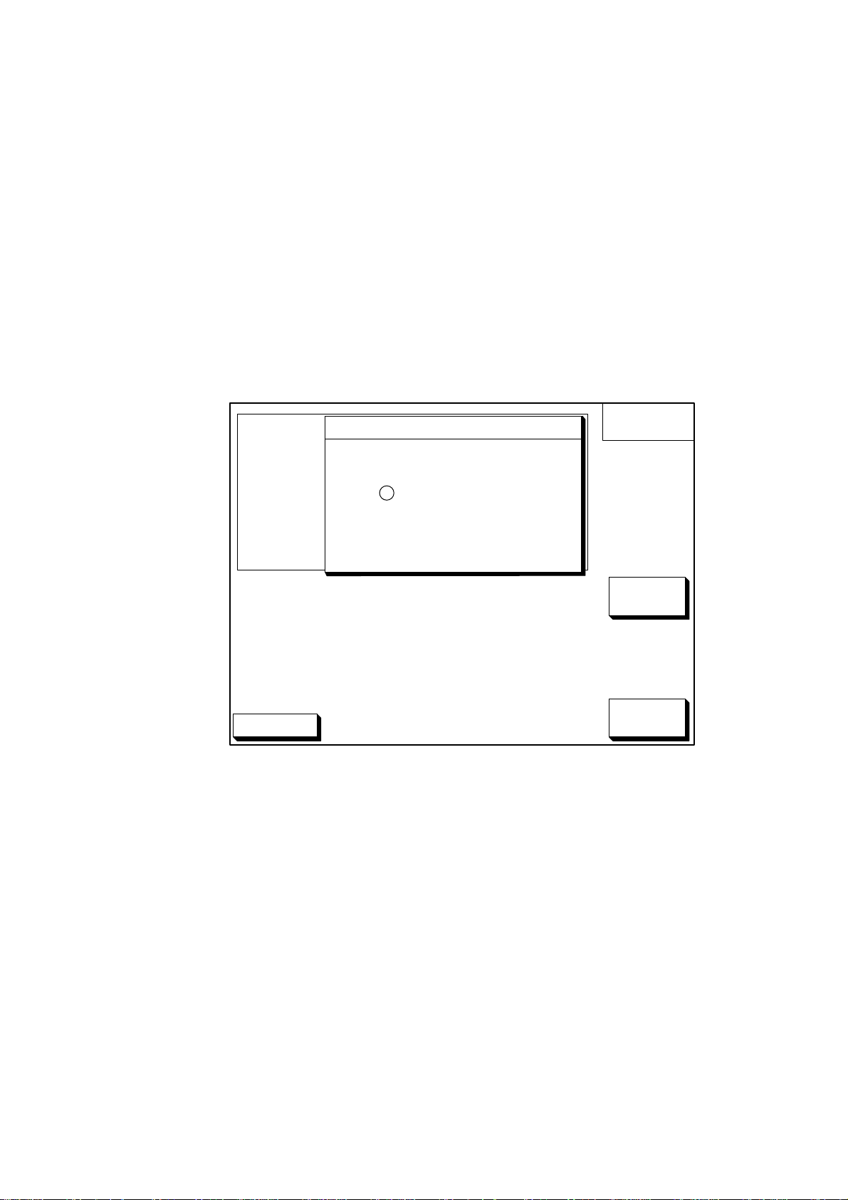
3.1 NMEA Setting
NMEA port
1. Press the [MENU] key.
2. Press the software key labeled "CONFIGURATION".
3. Press the software key labeled "SETUP NMEA PORT 1".
4. Select "FORMAT" by the arrow key.
5. Press the software key labeled "EDIT" to display the following message.
3. Initial Setting
s FORMAT NMEA 0183
DGPS 3D
Figure 3-1 Output Format Display, NMEA port
6. Select NMEA version desired by the arrow key.
OUTPUT FORMAT
VER 1.5
▲
NMEA0183 Ver1.5
' NMEA0183 Ver2.0
▼
SETUP
PORT 1
ENTER
CANCEL
7. Press the software key labeled "ENTER".
8. Press the [PLOT] key to finish.
3-1
Page 28
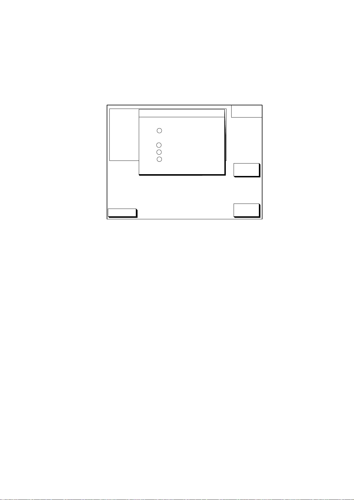
DGPS port
1. Press the [MENU] key.
2. Press the software key labeled "CONFIGURATION".
3. Press the software key labeled "SETUP NMEA/DGPS PORT 2".
4. Select "FORMAT" by the arrow key.
5. Press the software key labeled "EDIT" to display the following message.
s FORMAT NMEA 0183
DGPS 3D
OUTPUT FORMAT
▲
NMEA0183 Ver1.5
' NMEA0183 Ver2.0
RTCM104 (EXTRN)
RTCM104 (INTRN)
RTCM104 (OUTPUT)
▼
VER 1.5
▲▲▲
SETUP
PORT2
ENTER
CANCEL
Figure 3-2 Output Format Display, DGPS port
6. Select NMEA version, external DGPS or internal DGPS by the arrow key.
NMEA0183 Ver1.5/Ver2.0 : Select one when connecting PC or RS-232C
equipment.
RTCM104(EXTRN) : Select this when connecting external DGPS
beacon receiver.
RTCM104(INTRN) : Select this for builtin internal DGPS beacon
receiver.
RTCM104(OUTPUT) : Selecct this when outputting differential data of
the internal DGPS beacon receiver to other GPS
navigator.
Note 1) You cannot setup sentences when you select RTCM104 as the format.
Note 2) For RS-422 format, the level converter (IF-1432) is required for connection
of external equipment.
7. Press the software key labeled "ENTER".
8. Press the [PLOT] key to finish.
3-2
Page 29
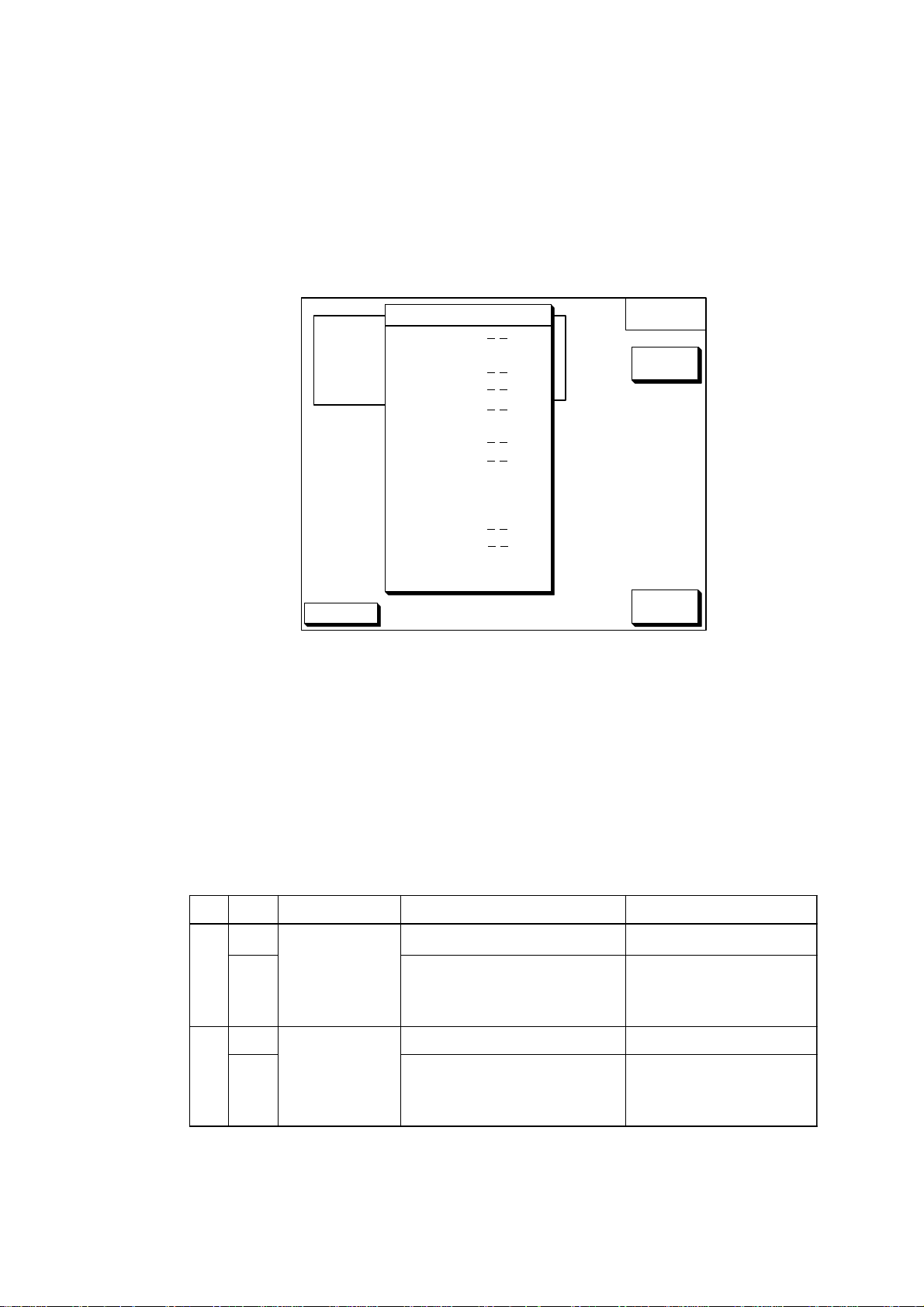
3.2 Output Data Sentences
Select output data sentences for external equipment as follows.
1. Press the [MENU] key.
2. Press the software key labeled "CONFIGURATION".
3. Press the software key labeled "SETUP NMEA PORT 1".
4. Press the software key labeled "SELECT SNTNC." to display the following list.
SELECT
SNTNC.
ON/OFF
s
SELECT SENTENCE
sAAM
APB ON
BOD
BWR
GGA
GLL ON
MTW
RMA
RMB ON
RMC ON
VTG ON
WPL
XTE
ZDA ON
DGPS 3D
RETURN
Figure 3-3 Output Date Sentences Display
5. Select data sentence you want to output data by the arrow key.
6. Press the software key labeled "ON/OFF". To output data, set to "ON".
7. Repeat to select other sentences.
8. Press the software key labeled "RETURN".
9. Press the [PLOT] key to finish.
Input/Output Sentences
troPO/ItamroFataDskrameR
tupnI
1
tuptuO
tupnI
2
tuptuO
3810-AEMN•
0.2.reV
5.1.reV
2611CEI•
3810-AEMN•
0.2.reV
5.1.reV
C232SR•
401MCTR•
.ylevitucesnoctupniebtonnaC:1*
1*LPW,MWD,1*LLTylnoreklatPG:LPW
2*DTG,WTM,TPD/TBD,ADZ,ETX
1*LPW,MWD,1*LLTylnoreklatPG:LPW
2*DTG,TPD/TBD,ADZ,ETX
.detcelessiALroCLnehwyllacitamotuatuptuO:2*
,AGG,RWB/CWB,DOB,BPA,MAA
,LPW,GTV,CMR,BMR,AMR,LLG
,AGG,RWB/CWB,DOB,BPA,MAA
,LPW,GTV,CMR,BMR,AMR,LLG
CWB:ELCRICTAERG
RWB:ENILBMUHR
TBD:5.1reVAEMN
TPD:0.2reVAEMN
CWB:ELCRICTAERG
RWB:ENILBMUHR
TBD:5.1reVAEMN
TPD:0.2reVAEMN
3-3
Page 30
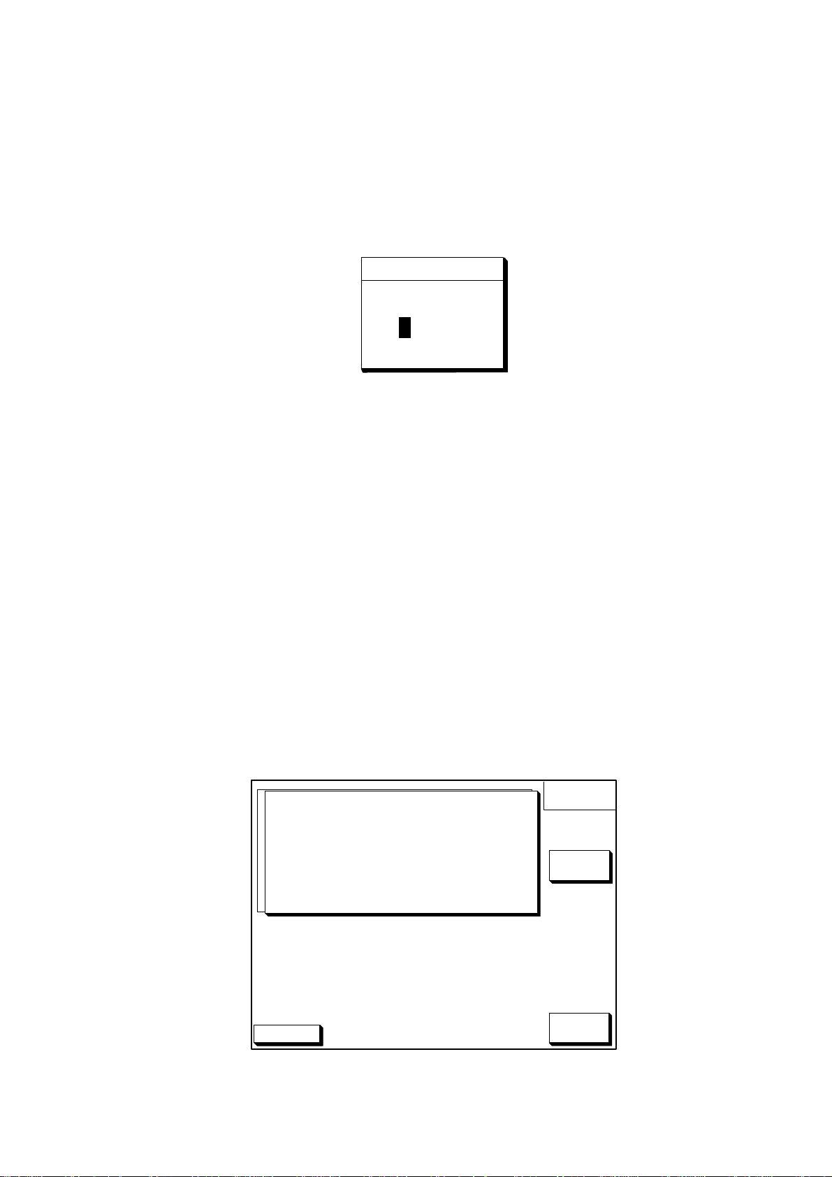
3.3 Antenna Height
1. Press the [MENU] key.
2. Press the software key labeled "GPS/DGPS/TD OPTIONS".
3. Press the software key labeled "GPS SETUP OPTIONS".
4. Select "ANT. HEIGHT" by the arrow key.
5. Press the software key labeled "EDIT" to display the following message.
Figure 3-4 Antenna Height Display
6. Enter the height (3 digits) of the antenna above sea level using the numeric
keys.
If you enter wrong antenna height, press the software key labeled "CLEAR".
ANT. HEIGHT
0 0 5 m
7. Press the [ENTER] key.
8. Press the [PLOT] key to return to finish.
3.4 Baud Rate Setting (GP-1850DF only)
This setting may not be done when AUTO MODE is selected.
1. Press the [MENU] key.
2. Press the software key labeled "GPS/DGPS/TD OPTIONS".
3. Press the software key labeled "DGPS SETUP OPTIONS" to display the following message.
s FORMAT NMEA 0183
DGPS MODE ON
BEACON FREQUENCY AUTO
s
BEACON BAUD RATE AUTO
DGPS ALARM OFF
VER 1.5
DGPS
OPTION
EDIT
DGPS 3D
Figure 3-5 DGPS Setup Options Display
3-4
RETURN
Page 31
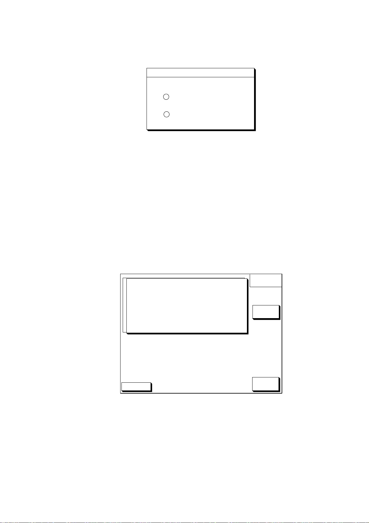
4. Confirm that "ON" is selected at "DGPS MODE" field for GP-1850DF.
5. Select "BEACON BAUD RATE" by the arrow key.
6. Press the software key labeled "EDIT" to display the following message.
BEACON BAUD RATE
▲
200
' 100
50
▼
Figure 3-6 Beacon Baud Rate Display
7. Select beacon baud rate corresponding to DGPS reference station to use.
8. Press the [ENTER] key.
9. Press the [PLOT] key to return to finish.
3.5 Beacon Frequency Setting (GP-1850DF only)
1. Press the [MENU] key.
2. Press the software key labeled "GPS/DGPS/TD OPTIONS".
3. Press the software key labeled "DGPS SETUP OPTIONS" to display the following message.
s FORMAT NMEA 0183
DGPS MODE ON
BEACON FREQUENCY AUTO
s
BEACON BAUD RATE AUTO
DGPS ALARM OFF
DGPS 3D
VER 1.5
DGPS
OPTION
EDIT
RETURN
Figure 3-7 DGPS Setup Options Display
3-5
Page 32
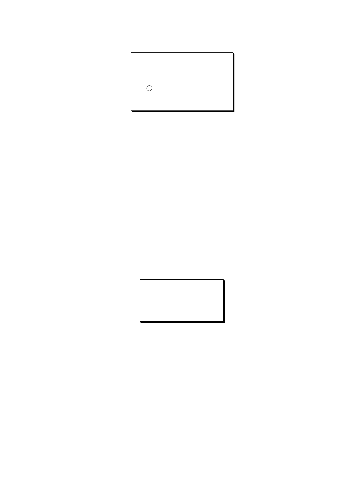
4. Select "BEACON FREQUENCY" by the arrow key.
5. Press the software key labeled "EDIT" to display the following message.
BEACON FREQUENCY
▲
' AUTO
MANUAL s 284.0 kHz
▼
Figure 3-8 Beacon Frequency Display
6. Select "AUTO" or "MANUAL" by the arrow key. When you select "MANUAL",
operate the cursor pad to move the cursor to frequency dialog box. And press
the arrow key to select the frequency desired.
7. Press the [ENTER] key.
8. Press the [PLOT] key to finish.
3.6 Depth Adjustment
1. Press the [MENU] key.
2. Press the software key labeled "DISPLAY OPTIONS".
3. Press the software key labeled "NEXT PAGE".
4. Select "DEPTH ADJ." by the arrow key.
5. Press the software key labeled "EDIT" to display the following message.
Figure 3-9 Depth Adjustment Display
6. Set depth adjustment by the arrow key. The adjustment range is -9.9~+9.9 ft.
For example, if the depth readout from the draft to the transducer is 5 feet lower
than actual depth, enter +5 feet.
DEPTH ADJ
▲
+ 0.0 f t
▼
7. Press the software key labeled "RETURN".
8. Press the [PLOT] key to finish.
3-6
Page 33
3.7 External Equipment Setup (Option)
This section shows you how to set up the GP-1850F/1850DF when external equipment is connected. If a water temperature/speed sensor is installed, you should
complete this section with the boat in the water and running, to confirm speed/
water temperature readout.
Speed Source
1. Press the [MENU] key.
2. Press the software key labeled "DISPLAY OPTIONS".
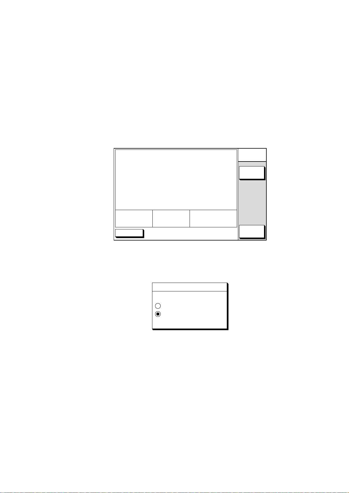
3. Press the software key labeled "NEXT PAGE" to display the following display.
s SPEED SOURCE GPS
TEMP SOURCE OWN XDCR
TEMP GRAPH OFF
ZOOM MARKER OFF
SPEED ADJ. +00%
TEMP ADJ. +00.0°F
DEPTH ADJ. +0.0ft
SPD
12.3kt
DGPS 3D
TEMP
62.5°F
DEPTH
2000.0ft
DISPLAY
SETUP2
EDIT
RETURN
Figure 3-10 Display Setup 2 Display
4. Select "SPEED SOURCE" by the arrow key.
5. Press the software key "EDIT" to display the following message.
SPEED SOURCE
▲
OWN PDDWHL
GPS
▼
Figure 3-11 Speed Source Display
6. Select source of speed by the arrow key; "OWN PDDWHL" (speed sensor) or
"GPS".
Adjust speed when you select "OWN PDDWHL". Refer to next page.
7. Press the software key labeled "ENTER".
8. Press the [PLOT] key to finish.
3-7
Page 34
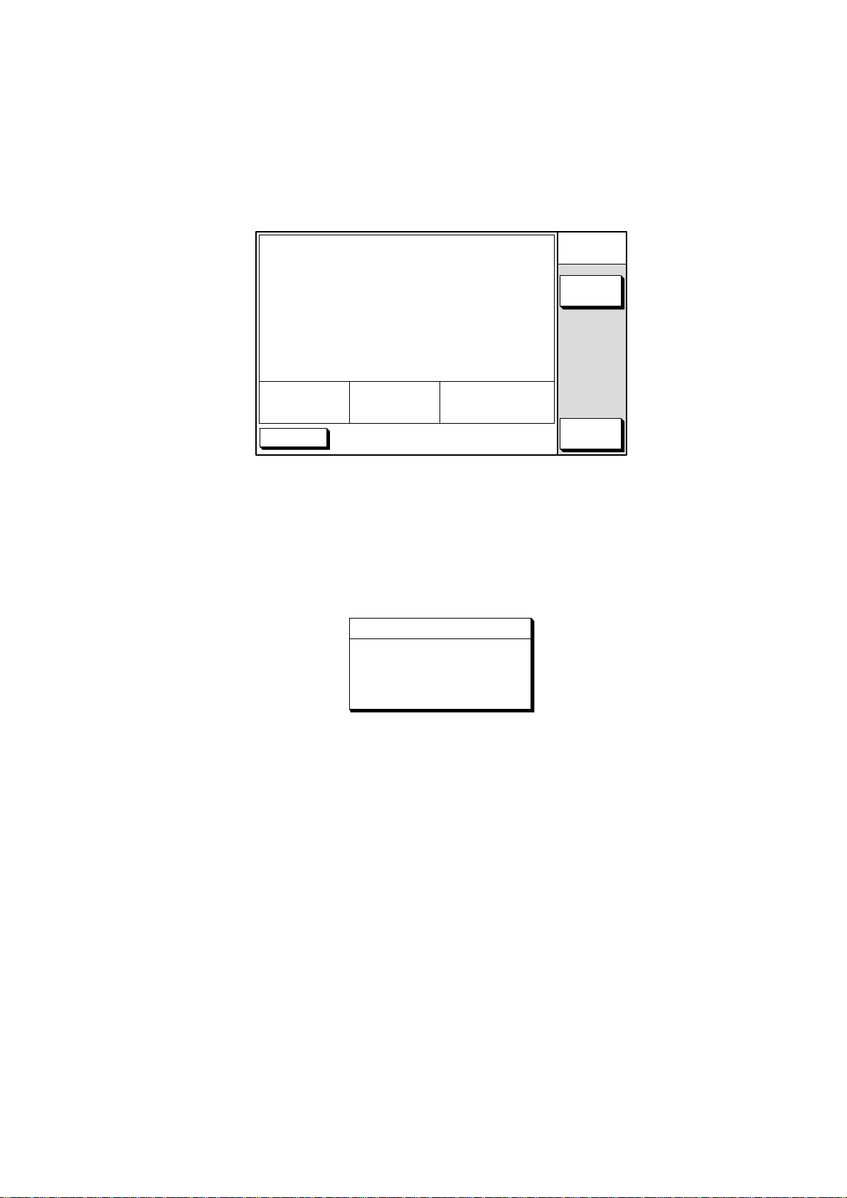
Speed Adjustment
Adjust speed when you select own speed source "OWN PDDWHL".
1. Press the [MENU] key.
2. Press the software key labeled "DISPLAY OPTIONS".
3. Press the software key labeled "NEXT PAGE" to display the following display.
s SPEED SOURCE GPS
TEMP SOURCE OWN XDCR
TEMP GRAPH OFF
ZOOM MARKER OFF
SPEED ADJ. +00%
TEMP ADJ. +00.0°F
DEPTH ADJ. +0.0ft
SPD
12.3kt
DGPS 3D
TEMP
62.5°F
DEPTH
2000.0ft
DISPLAY
SETUP2
EDIT
RETURN
Figure 3-12 Display Setup 2 Display
4. Select "SPEED ADJ." by the arrow key.
5. For speed sensor-equipped sets, you may offset the speed readout if it is wrong.
Run the boat at various speeds and watch the speed readout at the bottom of
the screen. If it is unreasonably wrong, press the software key "EDIT" to display the following message.
SPEED ADJ
▲
+ 00 %
▼
Figure 3-13 Speed Adjustment Display
6. Correct speed readout by the arrow key. The adjustment range is -50%~+50%.
For example, if readout is 10% lower than actual speed, enter +10%.
7. Press the software key "RETURN".
8. Press the [PLOT] key to finish.
T emperature Adjustment
1. Press the [MENU] key.
2. Press the software key labeled "DISPLAY OPTIONS".
3. Press the software key labeled "NEXT PAGE" to display the following display.
3-8
Page 35
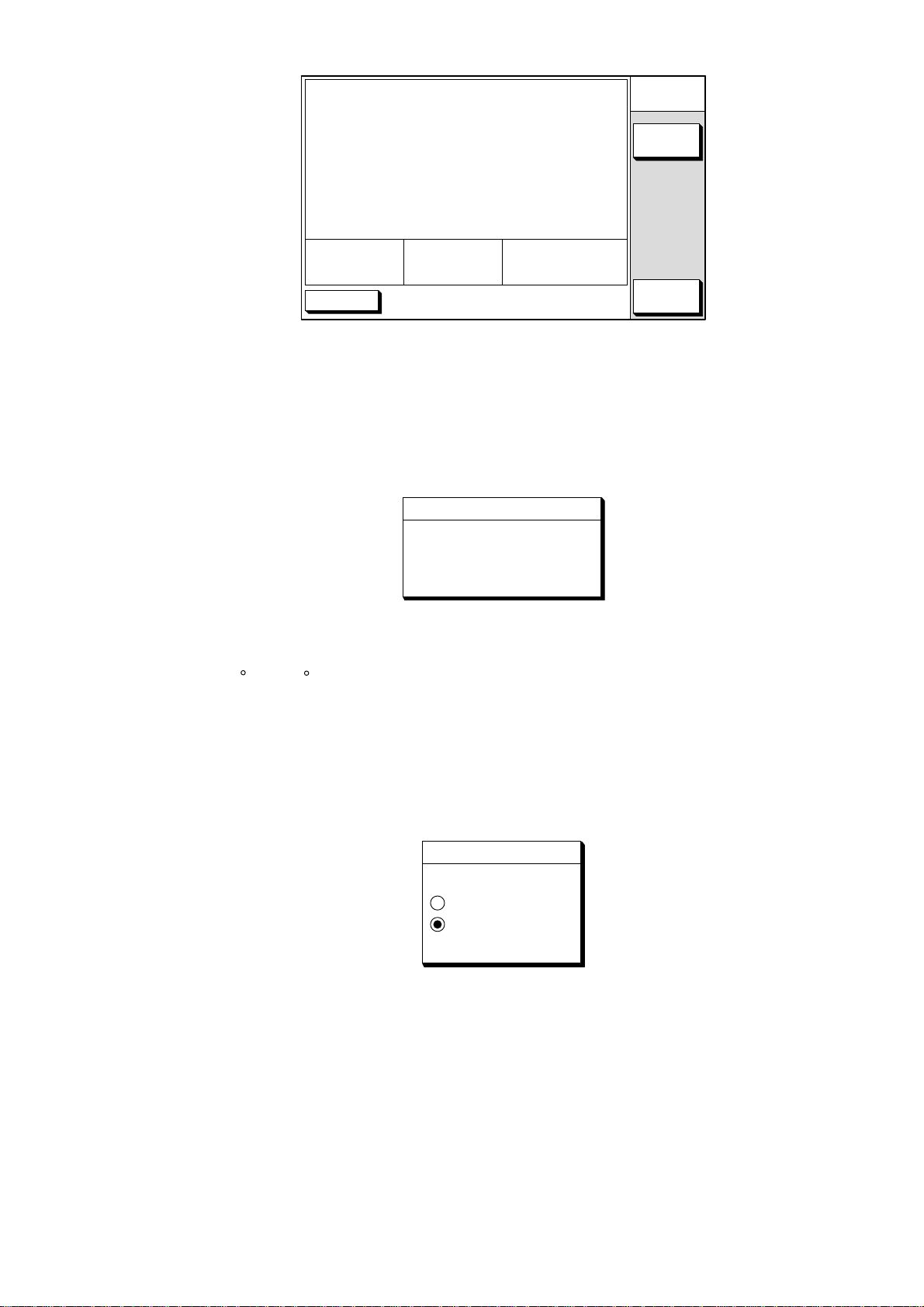
s SPEED SOURCE GPS
TEMP SOURCE OWN XDCR
TEMP GRAPH OFF
ZOOM MARKER OFF
SPEED ADJ. +00%
TEMP ADJ. +00.0°F
DEPTH ADJ. +0.0ft
DISPLAY
SETUP2
EDIT
SPD
12.3kt
DGPS 3D
TEMP
62.5°F
DEPTH
2000.0ft
RETURN
Figure 3-14 Display Setup 2 Display
4. Select "TEMP ADJ." by the arrow key.
5. For water temperature sensor-equipped sets, you may offset the water temperature readout if it is wrong. Watch the water temperature readout at the
bottom of the screen. If it is unreasonably wrong, press the software key labeled "EDIT" to display the following message.
TEMP ADJ
▲
+ 00.0 °F
▼
Figure 3-12 Temperature Adjustment Display
6. Correct water temperature readout by the arrow key. The adjustment range is
-99.9 ~+99.9 .
For example, if the readout is 2° higher than actual temperature, enter -2°.
7. Press the software key labeled "RETURN".
8. To display a water temperature graph (shows present water temperature), select "TEMP GRAPH" by arrow key.
9. Press the software key labeled "EDIT" to display following message.
TEMP GRAPH
▲
ON
OFF
▼
Figure 3-13 Temperature Graph Display
10.Select "ON".
11.Press the software key labeled "ENTER".
12.Press the [SNDR] key to finish.
3-9
Page 36
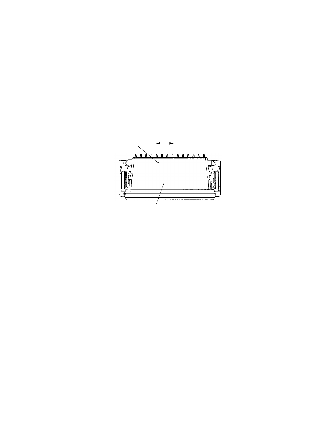
3.8 Selecting the Echo Sounder Output Power
The echo sounder output power can be selected for 600 W (for transducer 5205PSD, 520-5PWD, 520-5MSD) or 1 kW (50/200-1T), and the default setting is 600
W.
Note: Matching Box MB-1000 and cable assembly 02S4092 are required for 1kW
transducer connection. For details, see the interconnection diagram at the end of
this manual.
Attach the TX power label (supplied) to the place shown below, and draw a line
through the power which you don't use by oil base magic marker.
Between
these fins
Attach TX POWER
Label to here.
Warning Label
Figure 3-14 Display unit, top view
To change to 1 kW power, do the following:
1. Turn of f the power. Wait at least one minute before opening the cover, to allow
capacitors to discharge.
2. Remove nuts attached to XDR, SPD/TEMP. DGPS, NMEA and power supply
connectors at the rear of the display.
3. Remove nut and washer attached to the ANT connector.
4. Remove ten binding screws (M3 x 10) from the rear of the display unit to separate the panel/chassis assembly from the cover assembly.
3-10
Page 37
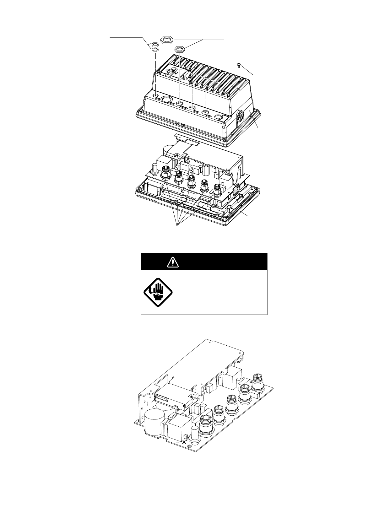
Binding screws
M3x10, 10 pcs.
Nuts
Nut, washer
Cover assembly
Panel/chassis assembly
Connector gasket
Figure 3-15 Removing cover assembly
WARNING
Do not connect the power
cable with the cover removed.
5. Move the jumper block on JP1 from 3-4 to 1-2 on the ANLG Board.
JP1
Figure 3-16 ANLG Board
3-11
Page 38
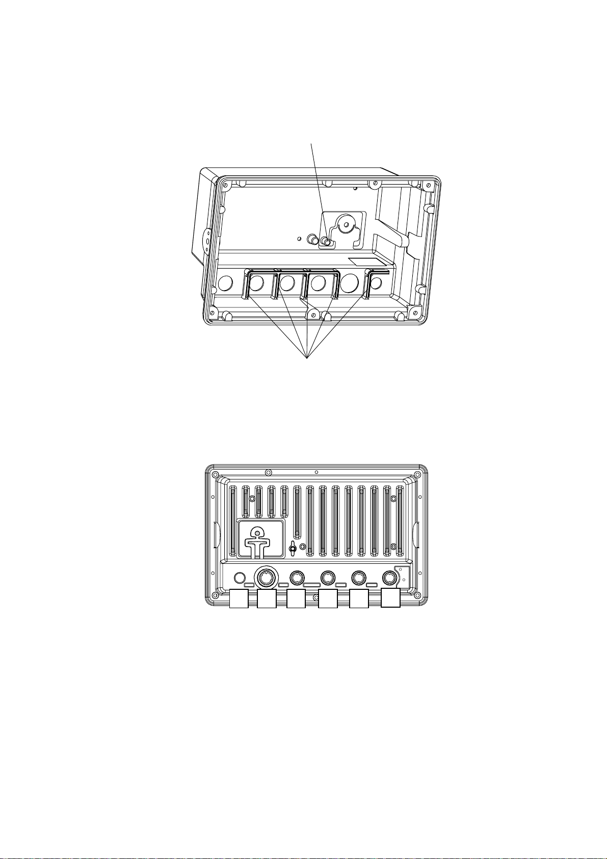
6. Remount the cover assembly.
Note: Confirm that the following parts are attached:
• Inside of the cover: Shield gaskets, GN gasket (See Figure 3-17.)
• On ANLG Board: Connector gasket (See Figure 3-15.)
GN gasket
Shield gaskets
Figure 3-17 Inside of the cover
7. Tighten nuts to torque shown below and in the order shown in Figure 3-18.
No. 1 through No. 5 : 7.5 - 8 kgf/cm
No. 6 : 14 -16 kgf/cm
+ GND
1 3
2
-
5
12 - 24
VDC
ANT XDR
6
4
2
TEMP/SPD
1
DGPS
NMEA
3
Figure 3-18 Display unit, rear view
8. Tighten ten binding screws (M3 x 10) fixing the cover to torque of 7.5-8 kgf/cm.
3-12
Page 39
4. Installation of DGPS Beacon Receiver (for GP-1850F)
The DGPS beacon receiver GR-7000A can be incorporated in the GP-1850F to provide it
with DGPS capability. Six installation kits are available as shown.
GR-802-1650-10A-018 (W/whip ant.) GR-802-1650-15A-018S (W/whip ant.)
GR-802-1650-10N-018 GR-802-1650-15N-018S
emaNepyT.oNedoCytQ
tinUannetnA810-APG174-140-0001
nocaeB
revieceR
annetnapihW
)ylnoepytA01(
rotcennoC
.yssA
eitelbaC001-VC223-075-0002
daehnaP
*swercs
*wercS403SUS21X3M509-508-0006
*.yssAelbaC
pmalCN2-PH000-075-0001
.yssAelbaC
wercS014SUS8X3159-208-0004
desutoN*
A0007-RG942-341-0001
2.1-WAF640-031-0001
042L-W-P6HP845-141-0001
W0072C01X3M504-188-0004
-D-7.0PL2-2LF.S
)121(THW
-D-7.0PL2-2LF.S
)052(THW
194-141-0001
778-341-0001
emaNepyT.oNedoCytQ
tinUannetnAS810-APG264-140-0001
nocaeB
revieceR
.yssAelbaC51-D3-SP-CNT076-331-0001
annetnapihW
)ylnoepytA51(
rotcennoC
.yssA
eitelbaC001-VC223-075-0002
daehnaP
*swercs
*wercS403SUS21X3M509-508-0006
*.yssAelbaC
pmalCN2-PH000-075-0001
.yssAelbaC
wercS014SUS8X3159-208-0004
desutoN*
A0007-RG942-341-0001
2.1-WAF640-031-0001
042L-W-P6HP845-141-0001
W0072C01X3M504-188-0004
-D-7.0PL2-2LF.S
)121(THW
-D-7.0PL2-2LF.S
)052(THW
194-141-0001
778-341-0001
GR-802-1650-10N-019 GR-802-1650-15N-019S
emaNepyT.oNedoCytQ
tinUannetnA910-APG255-140-0001
nocaeB
revieceR
rotcennoC
.yssA
eitelbaC001-VC223-075-0002
daehnaP
*swercs
*wercS403SUS21X3M509-508-0006
*.yssAelbaC
pmalCN2-PH000-075-0001
.yssAelbaC
wercS014SUS8X3159-208-0001
desutoN*
A0007-RG942-341-0001
042L-W-P6HP845-141-0001
W0072C01X3M504-188-0004
-D-7.0PL2-2LF.S
)121(THW
194-141-0001
-D-7.0PL2-2LF.S
)052(THW
778-341-0001
emaNepyT.oNedoCytQ
tinUannetnAS910-APG455-140-0001
nocaeB
revieceR
.yssAelbaC51-D3-SP-CNT076-331-0001
rotcennoC
.yssA
eitelbaC001-VC223-075-0002
daehnaP
*swercs
*wercS403SUS21X3M509-508-0006
*.yssAelbaC
pmalCN2-PH000-075-0001
.yssAelbaC
wercS014SUS8X3159-208-0004
desutoN*
A0007-RG942-341-0001
)121(THW
)052(THW
4-1
042L-W-P6HP845-141-0001
W0072C01X3M504-188-0004
-D-7.0PL2-2LF.S
-D-7.0PL2-2LF.S
194-141-0001
778-341-0001
Page 40
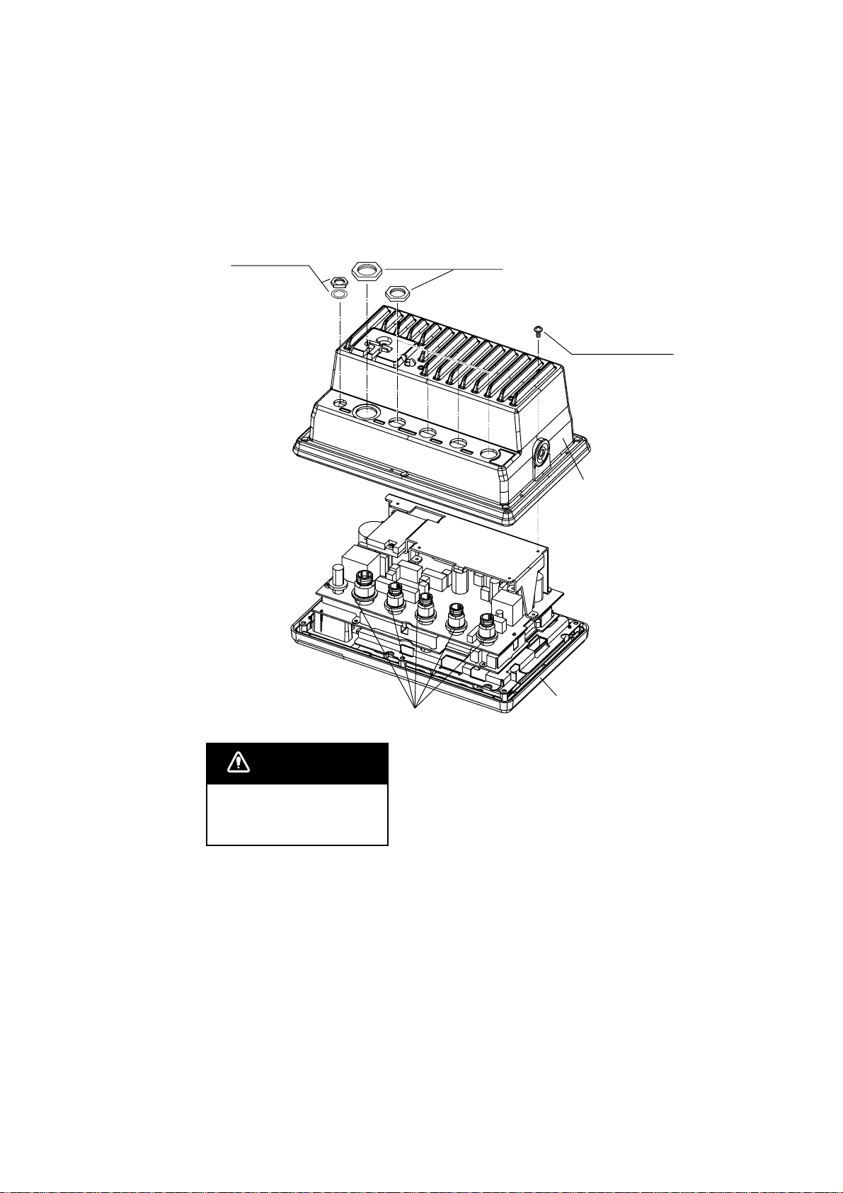
Disassembly
Procedure
1. Turn of f the power. Wait at least one minute before opening the cover, to allow
capacitors to discharge.
2. Remove nuts attached to DGPS, NMEA and power supply connectors at the
rear of the display unit.
Nut, washer
Nuts
Binding screws
M3x10, 10 pcs.
Cover assembly
Connector gasket
Panel/chassis assmbly
WARNING
Do not connect the power
cable with the cover
removed.
Figure 4-1 Removing cover assembly
3. Remove nut and washer attached to ANT connector.
4. Remove ten screws at rear of the display unit to detach panel/chassis assembly from the cover assembly.
4-2
Page 41
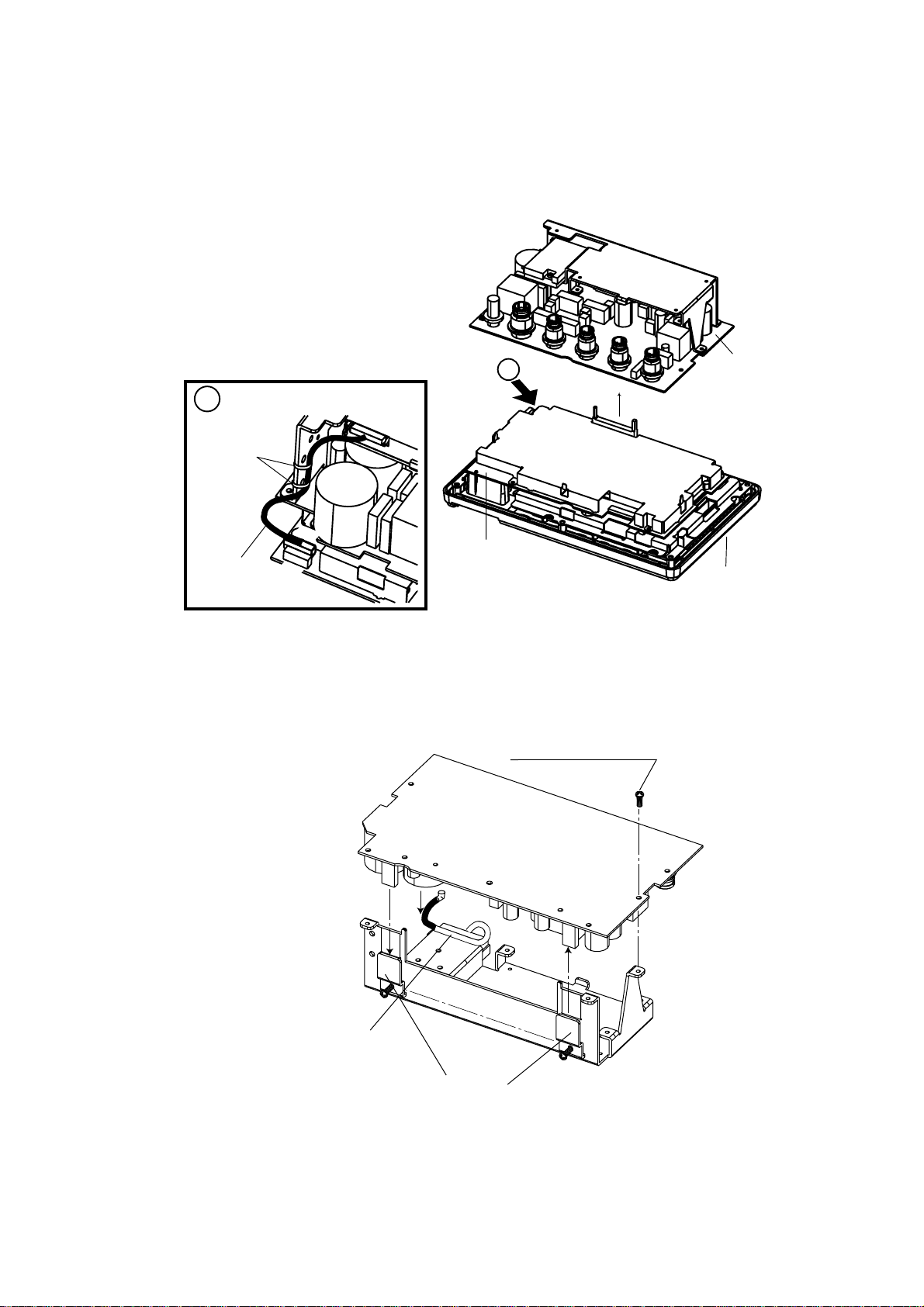
Installation of DGPS receiver
Procedure
1. Dismount chassis assembly from panel/chassis assembly by disconnecting the
connector and PH8P from J8 on MAIN Board shown in the figure below.
ANLG Board
14P0313B
Panel assembly
View
A
Remove
two ties.
Cable w/8P
connector
J7
A
Connector
J8
MAIN Board
14P0311B
(P)MAIN
Figure 4-2 Dismounting chassis assembly
2. Dismount heat sink from chassis assembly by unfastening three screws on the
ANLG board, loosening two screws at TR fixing plates and disconnecting the
connector of the mini pin coaxial cable.
ANLG Board
Screws (3 X 8), 3pcs.
Mini pin
coaxial cable
Figure 4-3 Chassis assembly
Heat Sink
TR fixing plate
4-3
Page 42
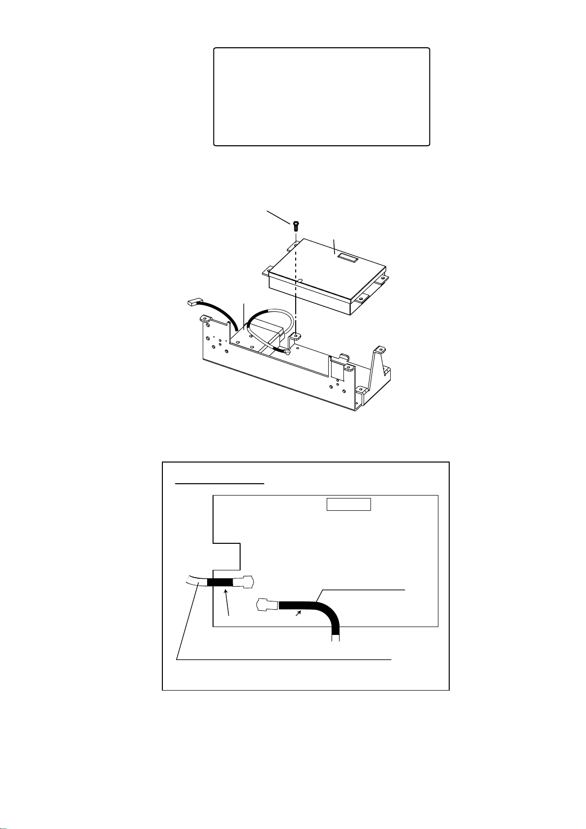
Handling of Coaxial Cable
• Do not touch the connector with bare hands;
use gloves.
• Use radio pincers to remove, and pull out
straightly.
• Plug in connector straightly.
3. Fasten the GR-7000A (DGPS beacon receiver) to the heat sink with four 3X8
screws as shown in the figure below.
Screws (3 X 8), 4pcs.
DGPS Beacon receiver
GR-7000A
GN-7707
Figure 4-4 Installation of DGPS beacon receiver
4. Open the cover of GR-7000A to connect two coaxial cables shown below.
J2
J1
Mini pin coax. cable
J3
Piece of shrink tubing
Cable Assy.
S.FL2-2LP0.7-D-WHT (250) (Supplied with DGPS kit)
From GN-7707
Figure 4-5 Connecting the coaxial cables in GR-7000A
5. Close the cover of GR-7000A passing the two cables out through respective
notches in the cover.
6. Plug PH6P-W-L240 connector to J2 on the GR-7000A through the cover.
4-4
Page 43
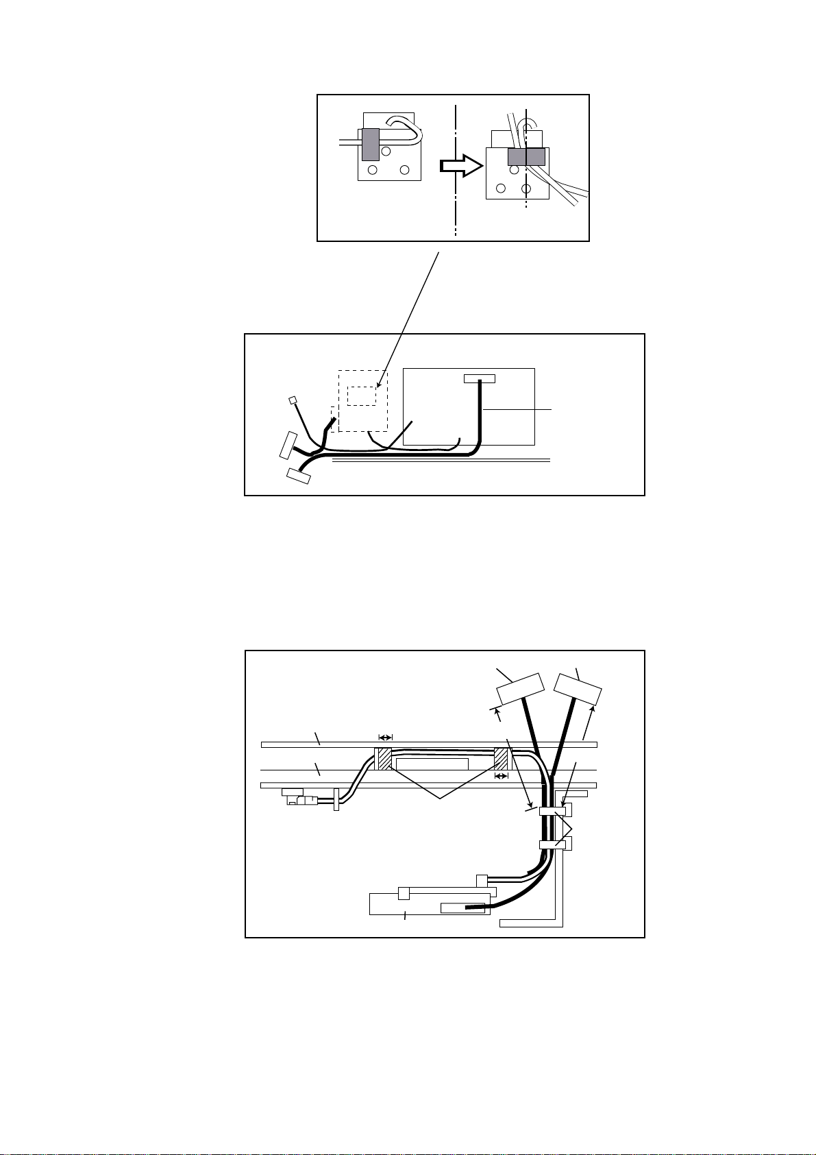
7. Wire cable assembly as shown in the figure below.
Reattach this tape as
shown right after the
DGPS connection.
To J8 of
ANLG Board
GN-7707
J2
GR-7000A
J1
J3
J2
Connector
PH6P-W-L240
Figure 4-6 Wiring the Cable assembly
8. Mount the ANLG board on the heat sink referring to step 2. Fasten cable assy.
S.FL2-2LP0.7-D-WHT (250), 8P connector cable and 6P connector cable by
cable tie (CV-100, supplied) as shown in the figure below. Fix cable assy. S.FL22LP0.7-D-WHT (250) with vinyl tape.
8P connector
40 to 45 mm
Cable
tie
MAIN Board
ANLG Board
J8
10 mm
6P connector
40 to 45 mm
10 mm
vinyl tape
GN-7707
Figure 4-7 Attaching cable tie
9. Connect J1 of GR-7000A to J8 of ANLG board (Refer to Figure 4-6).
10.Mount chassis assembly on the panel assembly. Connect 8P connector and 6P
connector to Main board as shown in Figure 4-8.
4-5
Page 44
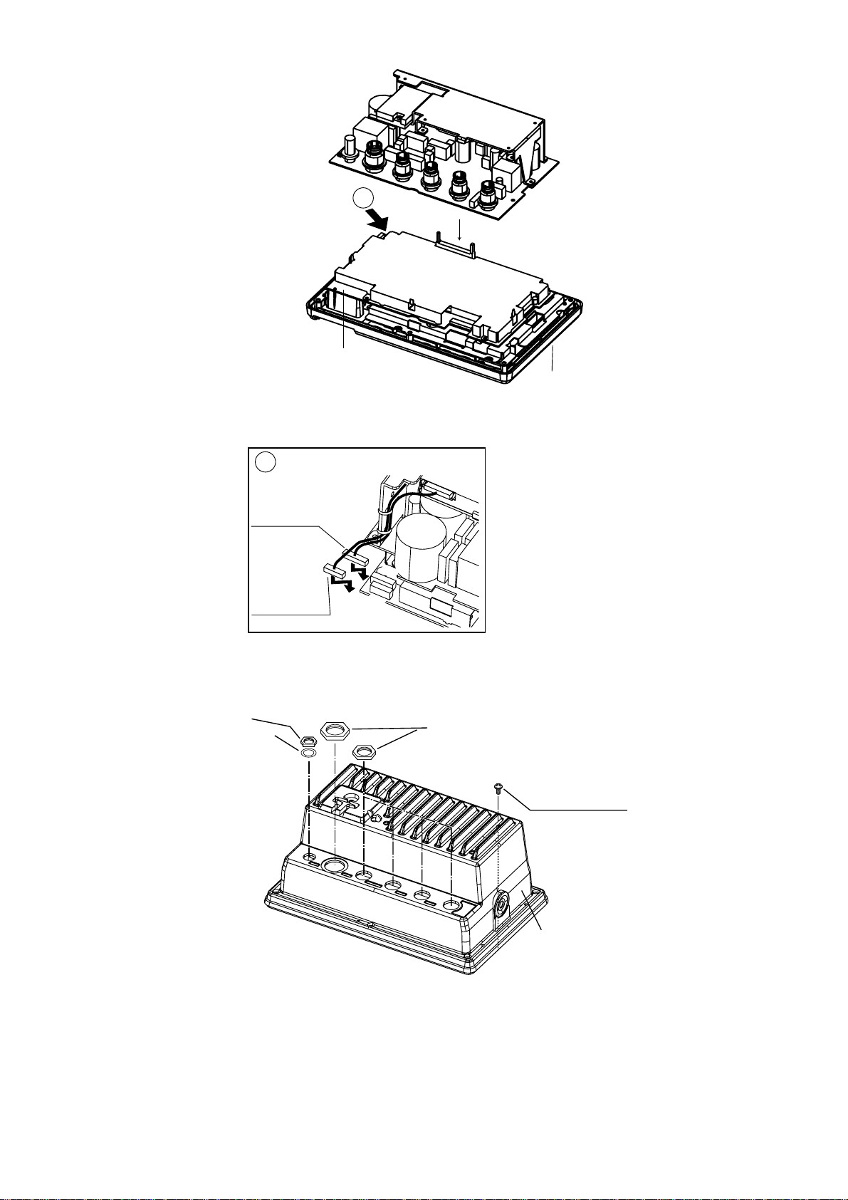
A
view
8P connector
to J8
A
MAIN Board
14P0311B
ANLG Board
14P0313B
Connector
Panel assembly
J8
6P connector
to J7
J7
Figure 4-8 Attaching chassis assembly
11.Reassemble the display unit.
Nut
Washer
(Torque:
1.37-1.57 N•m)
Figure 4-9 Remounting the cover
Panel
Assembly
Nuts
(Torque: 0.74-0.78 N•m)
Binding screws
M3x10, 10 pcs.
(Torque: 0.74-0.78 N•m)
Cover assembly
Note :
When reattaching the cover, confirm the following parts are attached.
• Inside of the cover : Shield gaskets, GN gasket (See Figure 4-10.)
• On ANLG Board : Connector gasket (See Figure 4-1.)
4-6
Page 45
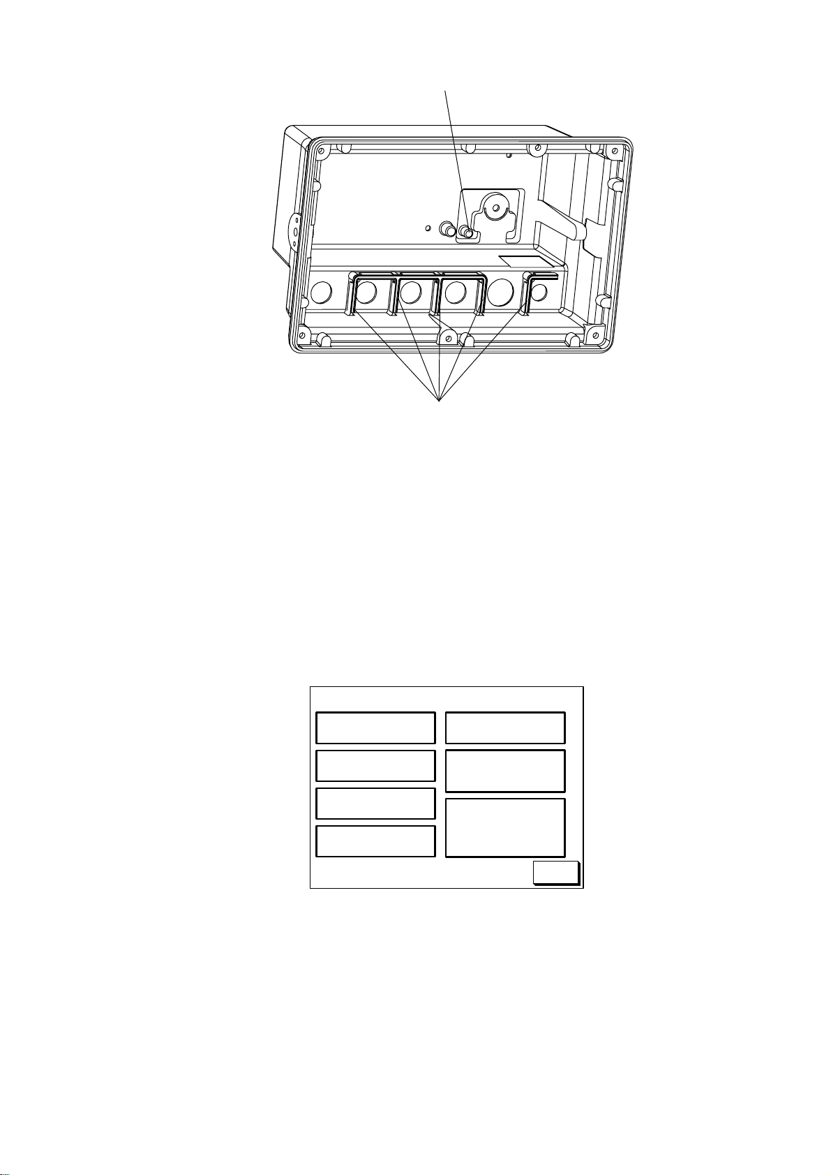
GN gasket
Shield gaskets
Figure 4-10 Inside of the cover
Checking the DGPS installation
1. Press the [MENU] key.
2. Press the software key labeled "CONFIGURATION".
3. Press the software key labeled "SYSTEM MENU".
4. Press the software key labeled "SELF TEST".
5. Press the software key labeled "MEMORY•I/O TEST" to display the following
message.
TEST
PROGRAM : OK
NO. 14518310XX
SRAM : OK
DRAM : OK
PORT1 : OK*
PORT2 : OK*
INTERNAL
BATTERY : OK
GPS
RECEIVER : OK
NO. 48502060XX
BEACON
RECEIVER : OK
NO. 0850182-0XX
NO.
RETURN
*: Special connections are required to check these port.
Otherwise, "--" (bar) appears.
Figure 4-10 Memory, I/O Test Display
6. Confirm that "BEACON RECEIVER: OK" is displayed.
7. Press the soft key labeled "RETURN".
8. Press the [PLOT] key to return the plotter display.
4-7
Page 46
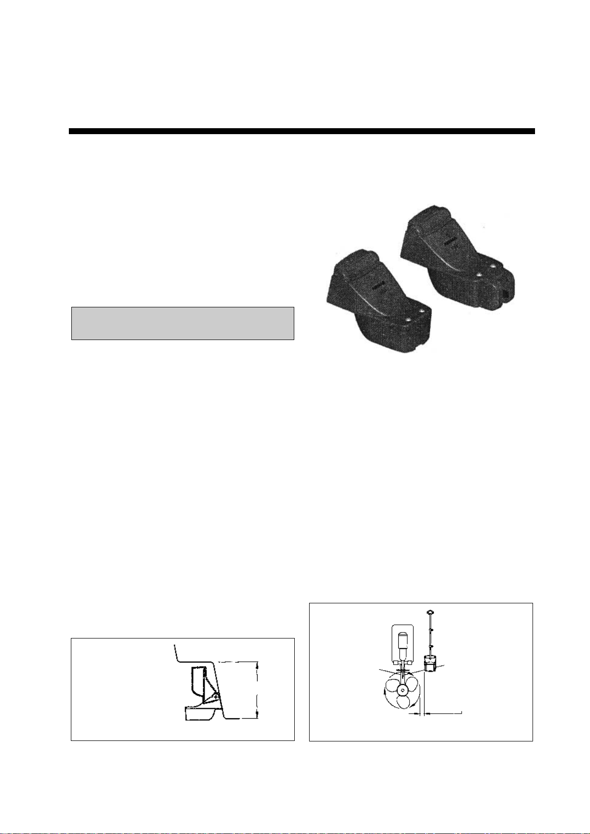
APPENDIX
TRIDUCER 525ST-PWC/PWD
This appendix provides a copy of the installation instructions for AIRMAR triducer. If you
loose the original supplied with the triducer, use this appendix.
INSTALLATION INSTRUCTIONS
Transom Mount Transducer or TRIDUCER®
Multisensor with Integral Release Bracket
U.S. Patents: 4,555,938; 4,644,787; 5,606,253; Des. 334,335
Model P66
Canadian Patent 1,233,341
IMPORTANT Please read the instructions completely before
proceeding with the installation. These directions supersede
any other instructions in your instrument manual if they differ.
Applications
• Powerboats with outboard, inboard, inboard/outboard, or jet drive.
Not recommended for boats with large or twin screw inboard motor.
• Bracket protects the sensor form frontal impact only
• Good operation up to 44kn (50MPH)
• Orients the sound beam vertically on hulls with a
deadrise angle up to 30°
• Adjusts to transom angles from 2-22°
Tools and Materials Needed
Scissors
Masking tape
Safety goggles
Dust mask
Electric drill
Drill bit for:
Bracket holes 4mm, #23, or 9/64”
Fiberglass hull chamfer bit (preferred), 6mm, or 1/4”
Transom hole 19mm or 3/4” (optional)
Cable clamp holes 3mm or 1/8”
Screwdrivers
Straight edge
Marine sealant
Pencil
Zip-ties
Water-based antifouling paint (mandatory in salt water).
Pre-test for Speed and Temperature
Connect the sensor to the instrument and spin the paddlewheel. Check
for a speed reading and the approximate air temperature. If there is no
reading, return the sensor to your place of purchase.
Mounting Location
To ensure the best performance, the sensor must be submerged in
aeration-free and turbulence-free water. Mount the sensor close to the
centerline of the boat. On slower heavier displacement hulls, positioning
it farther from the centerline is acceptable.
Allow adequate space above the bracket for it to release and rotate the
sensor upward (see Figure 1).
Caution: Do not mount the sensor in an area of turbulence or bubbles:
Near water intake or discharge openings;
Behind strakes, struts, fittings, or hull irregularities;
Behind eroding paint (an indication of turbulence).
Caution: Avoid mounting the sensor where the boat may be supported
during trailering, launching, hauling, and storage.
• Single drive boat—Mount on the starboard side at least 75mm
(3”) beyond the swing radius of the propeller (see Figure 2).
• Twin drive boat—Mount between the drives.
Height without
speed sensor
191mm (7-1/2")
Height with
speed sensor
213mm (8-1/2")
Figure 1. Height required at mounting location
height
75 mm(3")
minimum beyond
swing radius
Figure 2. Mounting location on single drive boat
AP-1
Page 47
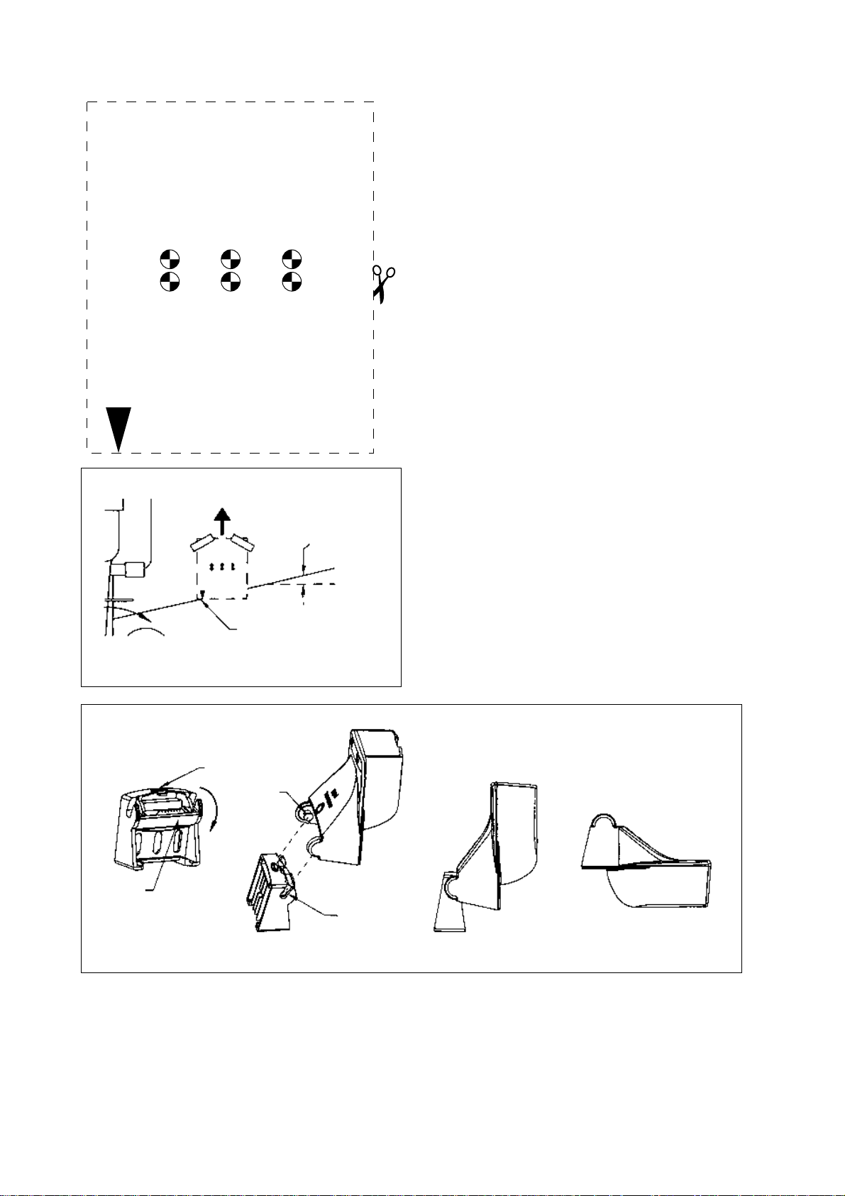
APPENDIX TRIDUCER 525ST-PWC/PWD
P66 Installation template
for starboard side of boat
Drill at locations labeled "B"
for the following transom angles:
16° through 22°
BB B
AA A
Drill at locations labeled "A"
for the following transom angles:
2° through 15°
Align arrow with bottom of transom
Align template vertically
deadrise angle
Caution: Never Use Solvents!
Cleaners, gasoline, paint, sealants, and other products may contain
strong solvents such as acetone which can attack many plastics
dramatically reducing their strength.
Installation
Bracket
1. Cut out the installation template shown on the left.
2. At the selected location, position the template, so the arrow at the
bottom is aligned with the bottom edge of the transom. Being sure
the template is parallel to the waterline, tape it in place
(see Figure 3).
Warning: Always wear safety goggles and a dust mask.
3. Using a 4mm, #23, or 9/64” bit, drill three holes 22mm (7/8”) deep
at the locations indicated. To prevent drilling too deeply, wrap
masking tape around the bit 22mm (7/8”) from the point.
Fiberglass hull—Minimize surface cracking by chamfering the
gelcoat. If a chamfer bit or countersink bit is not available, start
drilling with a 6mm or 1/4” bit to a depth of 1mm (1/16”).
4. If you know your transom angle—The bracket is designed for a
standard 13° transom angle.
11°-18° angle—No shim is required. Skip to “Adjusting”, step 3.
Other angles—The shim is required. Skip to “Adjusting”, step 2.
If you do not know the transom angle—Temporarily attach the
bracket and sensor to the transom to determine if the plastic shim is
needed.
5. Using the two #10 x 1-1/4” self-tapping screws, temporarily screw
the bracket to the hull. Do not tighten the screws completely at this
time. Follow the instructions for “Attaching the Sensor to the
Bracket”, steps 1-4 before proceeding with “Adjusting”.
Figure 3. Template position
Step 1 Step 4Step 3Step 2
latch
retaining
cover
slope of hull
parallel to
waterline
Align template arrow with
bottom edge of transom
pivot
arm (2)
slot (2)
Figure 4. Attaching the sensor to the bracket
Adjusting
1. Using a straight edge, sight the underside of the sensor relative to
the underside of the hull. The stern of the sensor should be
1-3mm (1/16-1/8”) below the bow of the sensor or parallel to the
bottom of the hull (see Figure 5).
Caution: Do not position the bow of the sensor lower than the
stern because aeration will occur.
AP-2
Page 48
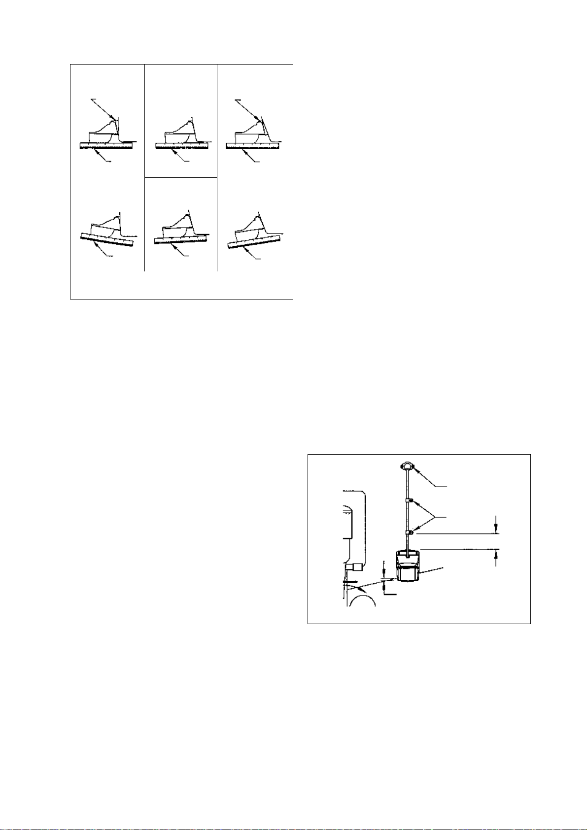
2°-10° transom angle 19°-22° transom angle
shim with
taper down
angle
reversed
Figure 5. Sensor angle adjustment on transom
2. To adjust the sensor’s angle relative to the hull, use the tapered
plastic shim provided. If the bracket has been temporarily fastened
to the transom, remove it, Key the shim in place on the back of the
bracket.
2°-10° transom angle (stepped transom and jet boats)—Position
the shim with the tapered end down.
19°-22° transom angle (small aluminum and fiberglass boats)—
Position the shim with the tapered end up.
3. If the bracket has been temporarily fastened to the transom,
remove it. Apply a marine sealant to the threads of the two
#10 x 1-1/4” self tapping screws to prevent water seeping into the
transom. Screw the bracket to the hull. Do not tighten the screws
completely at this time.
4. Repeat step 1 to ensure that the angle of the sensor is correct.
Caution: Do not position the sensor farther into the water than
necessary to avoid increasing drag, spray, and water noise and
reducing boat speed.
5. Using the vertical adjustment space on the bracket slots, slide the
sensor up or down to provide a projection of 3mm (1/8”). Tighten
the screws (see Figure 6).
11° transom angle
NO SHIM
YES YESYES
parallelparallel parallel
12-18° transom angle
NO SHIM
YES NONO
slight
angle
shim with
taper up
angle
too steep
APPENDIX TRIDUCER 525ST-PWC/PWD
Cable Routing
Route the sensor cable over the transom, through a drain hole, or
thorough a new hole drilled in the transom above the waterline.
Caution: Never cut the cable or remote the connector; this will void the
warranty.
Warning: Always wear safety goggles and a dust mask.
1. If a hole must be drilled, choose a location well above the waterline.
Check for obstructions such as trim tabs, pumps, or wiring inside
the hull. Mark the location with a pencil. Drill a hole through the
transom using a 19mm or 3/4” bit (to accommodate the connector).
2. Route the cable over or through the transom.
3. On the outside of the hull secure the cable against the transom
using the cable clamps. Position a cable clamp 50mm(2”) above the
bracket and mark the mounting hole with a pencil (see Figure 6).
4. Position the second cable clamp halfway between the first clamp
and the cable hole. Mark this mounting hole.
5. If a hole has been drilled in the transom, open the appropriate slot
in the transom cable cover. Position the cover over the cable where
it enters the hull. Mark the two mounting holes.
6. At each of the marked locations, use a 3mm or 1/8” bit to drill a
hole 10mm (3/8”) deep. The prevent drilling too deeply, wrap
masking tape around the bit 10mm (3/8”) from the point.
7. Apply marine sealant to the threads of the #6 x 1/2” self-tapping
screw to prevent water from seeping into the transom. If you have
drilled a hole through the transom, apply marine sealant to the
space around the cable where it passes through the transom.
8. Position the two cable clamps and fasten them in place. If used,
push the cable cover over the cable and screw it in place.
9. Route the cable to the instrument being careful not to tear the cable
jacket when passing it though the bulkhead(s) and other parts of the
boat. To reduce electrical interference, separate the sensor
cable from other electrical wiring and “noise” sources. Coil any
excess cable and secure it in place with zip-ties to prevent damage.
10. Refer to your echosounder owner’s manual to connect the sensor
to the instrument.
cable cover
cable clamp
Attaching the Sensor to the Bracket
1. If the retaining cover near the top of the bracket is closed, open it by
depressing the latch and rotating the cover downward
(see Figure 4).
2. Insert the sensor’s pivot arms into the slots near the top of the
bracket.
3. Maintain pressure until the pivot arms click into place.
4. Rotate the sensor downward until the bottom snaps into the
bracket.
5. Close the retaining cover to prevent the accidental release of the
sensor when the boat is underway.
Hull projection
3mm (1/8")
Figure 6. Vertical adjustment and cable routing
50mm (2")
AP-3
Page 49
Page 50
Page 51
Page 52
Page 53
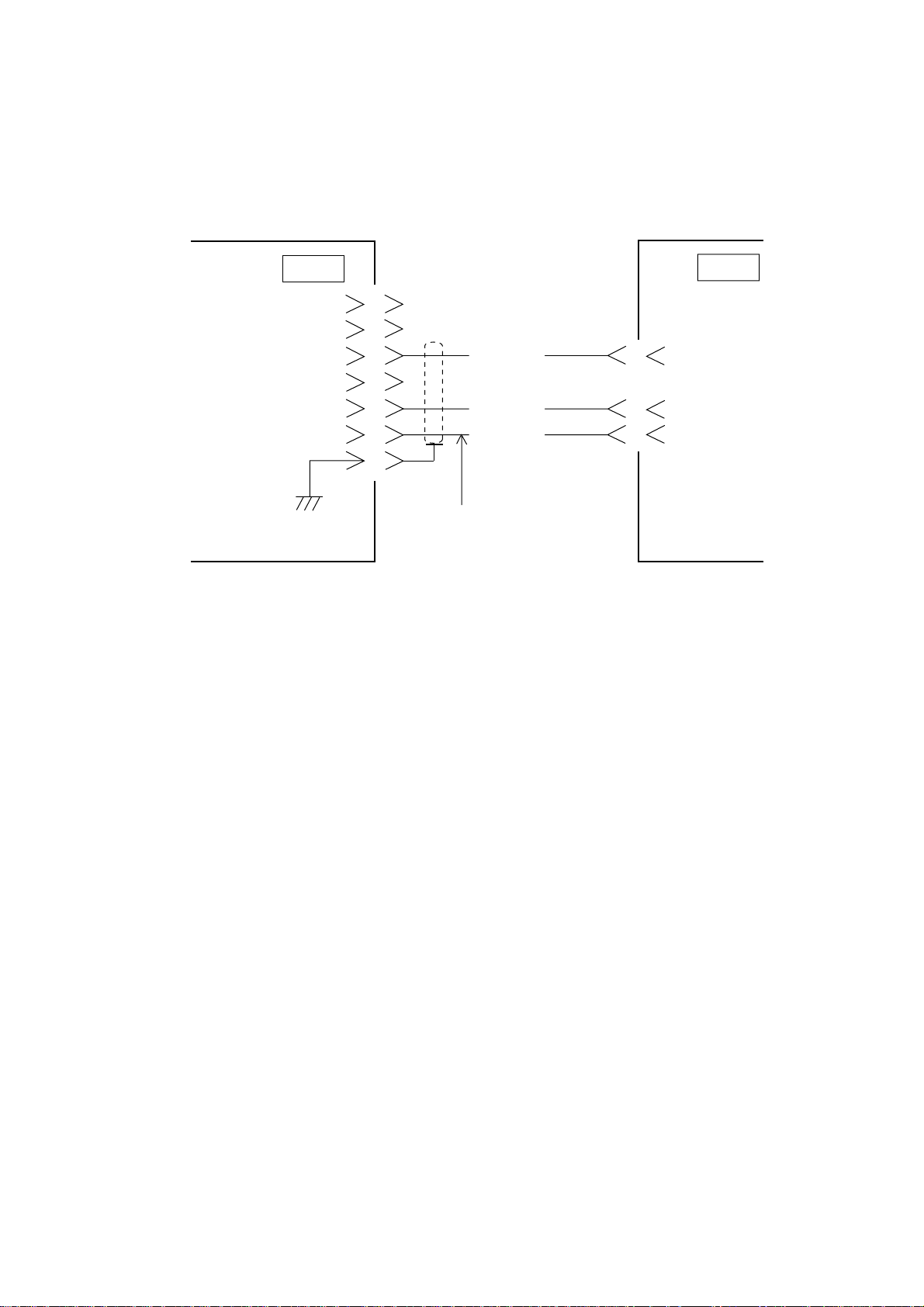
Connecting DGPS beacon receiver
A DGPS beacon receiver whose output format is RS-232C can be connected to
the GP-1850F.
Below is the example of interconnection between the GP-1850F and FURUNO
beacon receiver GR-80.
GP-1850F
Figure 4-11 Connecting DGPS beacon receiver
DGPS
RD
SD
SG
1
2
3
4
5
6
7
Can use MJ-A7SPF0003-050
(OPTION).
YELLOW
RED
BLUE
GR-80
(setting RS-232C)
1
3
7
DATA
TD-B
RD-B
GND
4-8
Page 54
Page 55
Page 56
Page 57
Page 58
Page 59
Page 60
Page 61
Page 62
Page 63
 Loading...