

Page 1

COLOR VIDEO PLOTTER GD-1700C
VIDEO PLOTTER GD-1700
Page 2

(
C
9-52, Ashihara-cho,
Nishinomiya, Japan
Telephone: 0798-65-2111
Telefax: 0798-65-4200
All rights reserved.
Printed in Japan
PUB. No. IME-44090-D
TATA)
GD-1700/1700C
Your Local Agent/Dealer
FIRST EDITION : APR. 2001
D : OCT. 11, 2001
Page 3
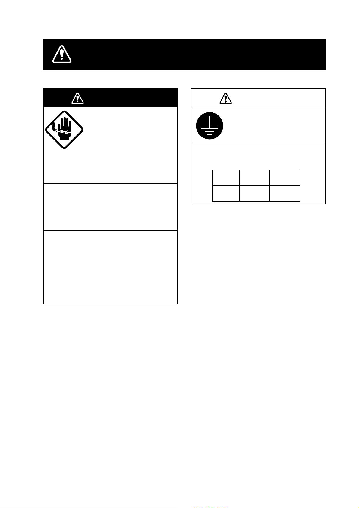
SAFETY INSTRUCTIONS
WARNING
ELECTRICAL SHOCK HAZARD
Do not open the equipment
unless totally familiar with
electrical circuits and
service manual.
Only qualified personnel
should work inside the
equipment.
Turn off the power at the switchboard
before beginning the installation.
Fire or electrical shock can result if the
power is left on.
Be sure that the power supply is
compatible with the voltage rating of
the equipment.
Connection of an incorrect power supply
can cause fire or equipment damage. The
voltage rating of the equipment appears
on the label above the power connector.
CAUTION
Ground the equipment to
prevent electrical shock and
mutual interference.
Observe the following compass safe
distances to prevent interference to a
magnetic compass:
Standard Steering
compass compass
Display
unit
0.65 m 0.45 m
i
Page 4

TABLE OF CONTENTS
EQUIPMENT LISTS ...................................................................................................... iii
SYSTEM CONFIGURATIONS....................................................................................... iv
1. DISPLAY UNIT INSTALLATION.............................................................................. 1
1.1 Mounting Considerations.........................................................................................................1
1.2 Mounting.................................................................................................................................. 2
2. WIRING.................................................................................................................... 5
2.1 Wiring....................................................................................................................................... 6
2.2 How to Connect a PC.............................................................................................................. 8
3. INITIAL SETTINGS ................................................................................................. 9
3.1 How to Access the Installation Menu......................................................................................9
3.2 Network Setup....................................................................................................................... 10
3.3 Navigation Data Source ........................................................................................................ 12
3.4 Setting up GPS Receiver GP-310B ...................................................................................... 14
3.5 Setting up Data Ports ............................................................................................................ 15
3.6 Remote Controller Setting..................................................................................................... 17
PACKING LIST............................................................................................................A-1
OUTLINE DRAWINGS ................................................................................................D-1
INTERCONNECTION DIAGRAM ................................................................................S-1
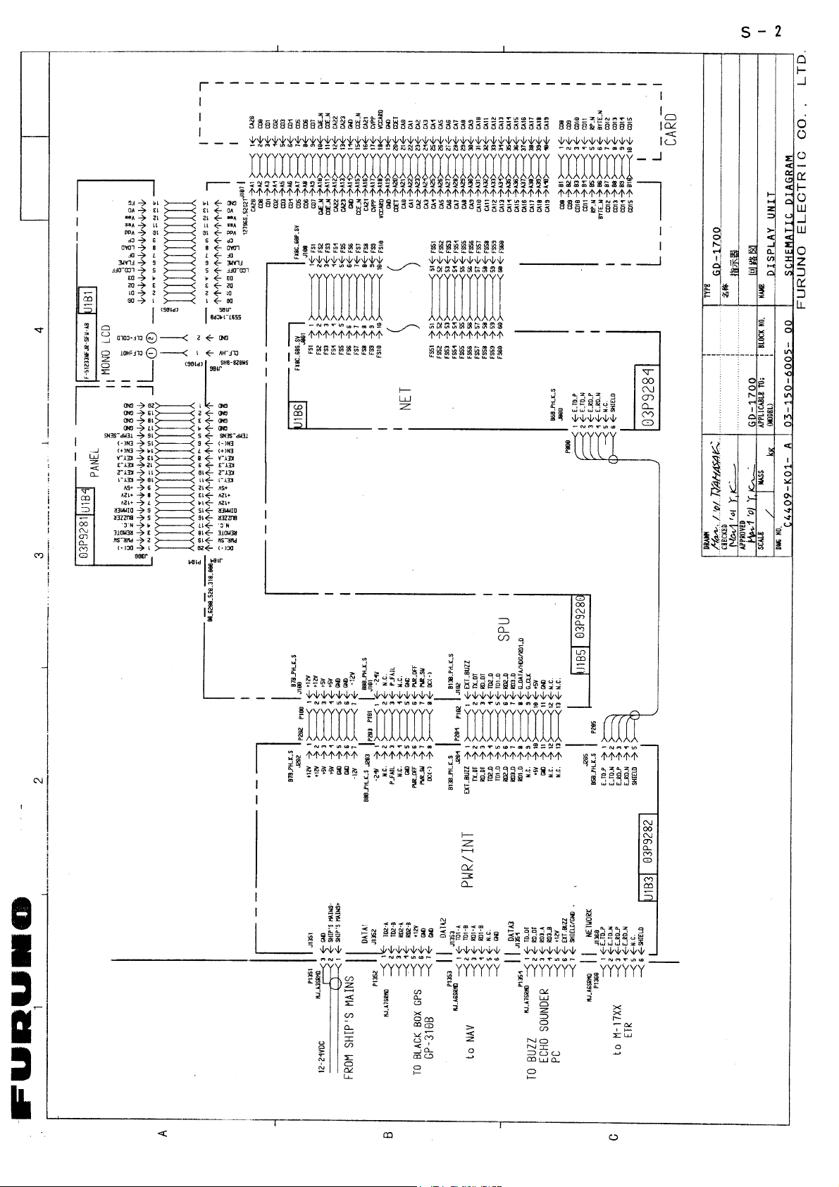
SCHEMATIC DIAGRAMS............................................................................................S-2
ii
Page 5
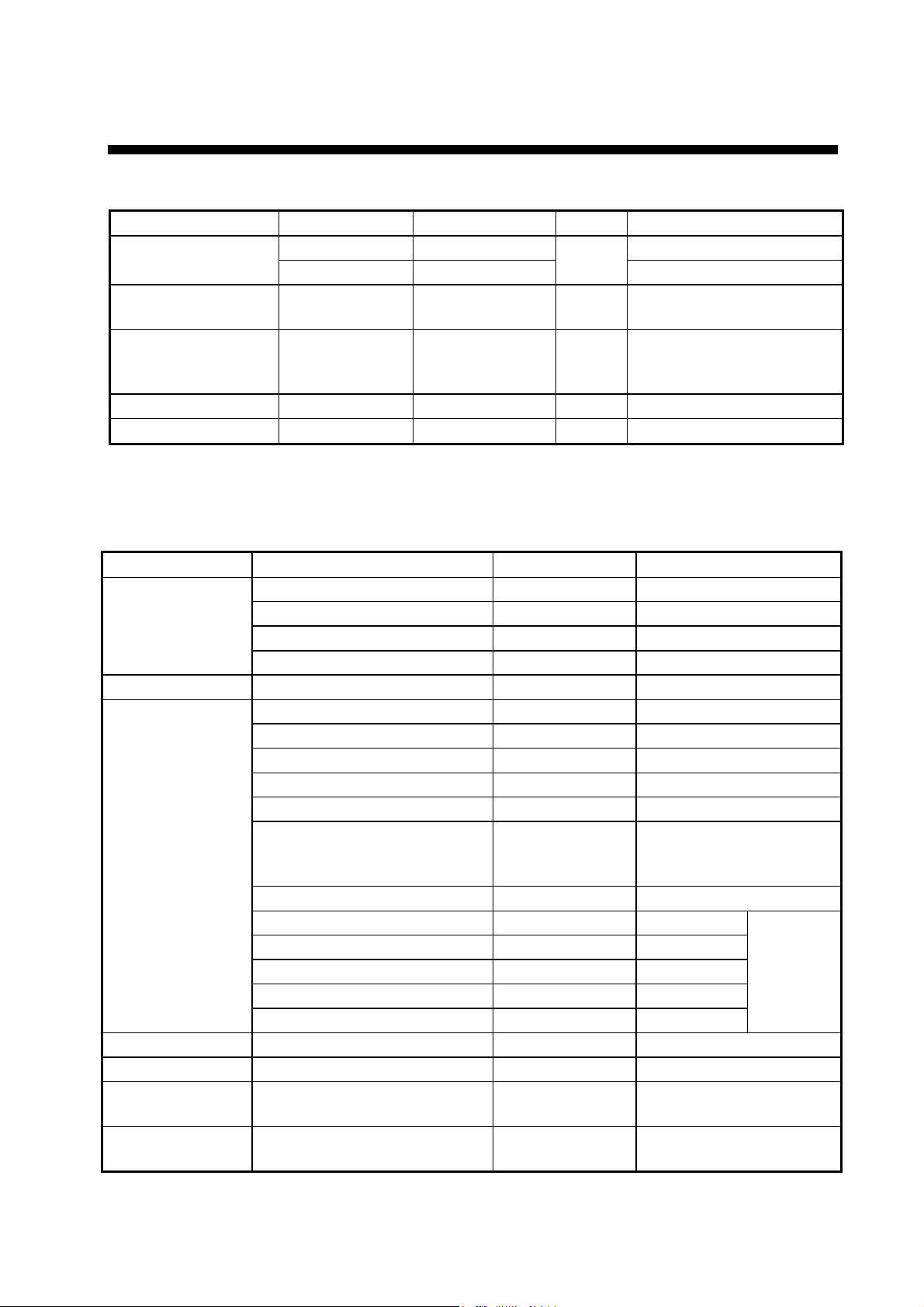
EQUIPMENT LISTS
Standard supply
Name Type Code No. Qty Remarks
GD-1700 — GD-1700 Display Unit
GD-1700C — 1 GD-1700C
Remote Controller
Set
Installation
Materials*
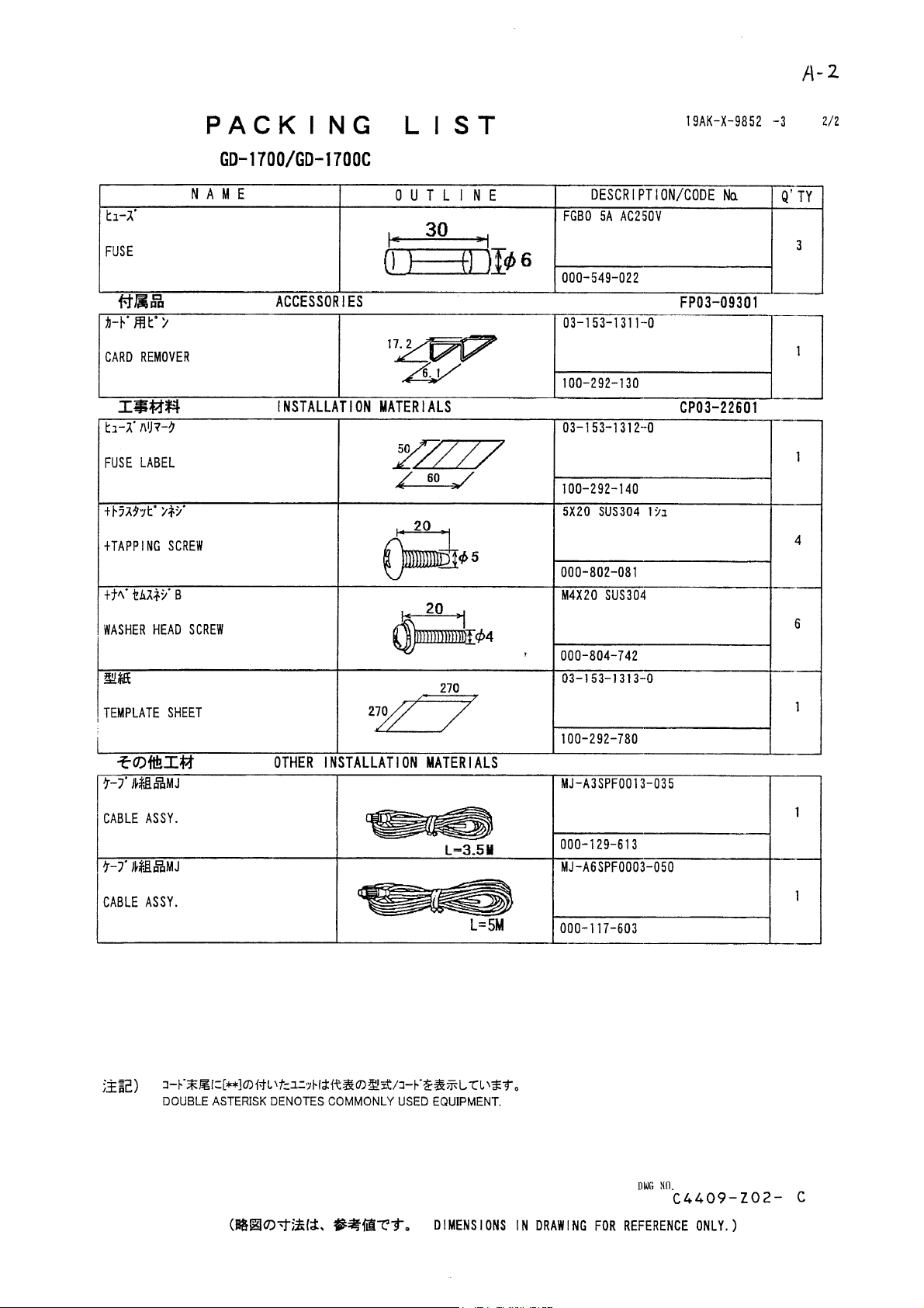
Accessories* FP03-09301 008-522-970 1 set
Spare Parts* SP03-13901 000-080-008 1set
Optional supply
RMC-100 — 1 set
CP03-22600 000-080-009 1 Cable assy. MJ-A3SPF0013-035
Cable assy. MJ-A6SPF0003-050
CP03-22601
*: See the back of this manual for details.
Name Type Code No. Remarks
Rectifier
External Buzzer OP03-136 000-086-443
Signal Cable
RAM Card 00RAM02MC-004 004-371-790 2 MB
Chart Card — — Specified when ordering
Remote Controller
Set
Modification kit for
C-map
PR-62 000-013-484 100 VAC
PR-62 000-013-485 110 VAC
PR-62 000-013-486 220 VAC
PR-62 000-013-487 230 VAC
MJ-A6SPF0012-050 000-134-424 For navigator, 5 m
MJ-A6SPF0012-100 000-133-817 For navigator, 10 m
MJ-A6SPF0007-100 000-125-237 For compass, 10 m
MJ-A6SPF0011-050 000-132-244 w/6P connector, 5 m
MJ-A6SPF0011-100 000-132-336 w/6P connector, 10 m
MJ-A7SPF0007-050 000-144-418 w/7P connector, 5 m, for
external buzzer, PC,
NMEA
MJ-A6SRMD/TM11AP8-005 000-144-463 Conversion cable for HUB
MJ-A6SPF0014-010 000-144-421 1 m
MJ-A6SPF0014-050 000-144-422 5 m
MJ-A6SPF0014-100 000-144-423 10 m
MJ-A6SPF0014-200 000-144-424 20 m
MJ-A6SPF0014-300 000-144-425 30 m
RMC-100 000-089-885
MODEL17*2/C-MAP 008-525-200 See modification
instruction E42-00005-x
For
NavNet
iii
Page 6
v
SYSTEM CONFIGURATIONS
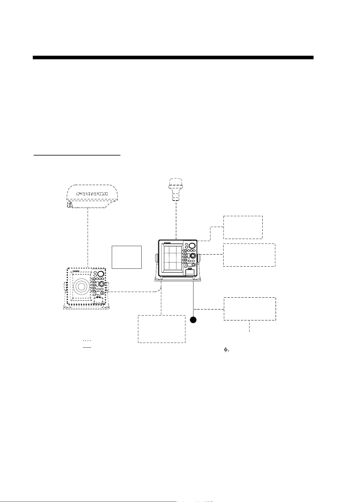
All NavNet products incorporate a “network circuit board” to integrate each NavNet product
on board through an optional LAN cable (Ethernet 10BASE-T). Each NavNet product is
assigned an IP address to enable transfer of images between NavNet products. For
example, video plotter pictures can be transferred to a radar and vice versa. Pictures
received via the NavNet may be adjusted at the receiving end.
A NavNet system may consist of up to three display units and one network sounder. For a
system incorporating three or more products a “hub” is required to process data.
Single-unit NavNet system
Antenna Unit
(ex. MODEL 1722/1722C)
GPS Receiver
GP-310B
Other NavNet Unit
(Model 1722, etc.)
: Option
: Standard
Remote
Controller
RMC-100
Single-unit NavNet system
Display Unit
GD-1700C
GD-1700
Network Sounder
ETR-6/10N
12-24 VDC
Echo sounder
Navigator
Echo sounder
External buzzer
PC
Rectifier
PR-62
Ship's Mains
100/110/115/220/230 VAC,
f
, 50/60 Hz
1
i
Page 7
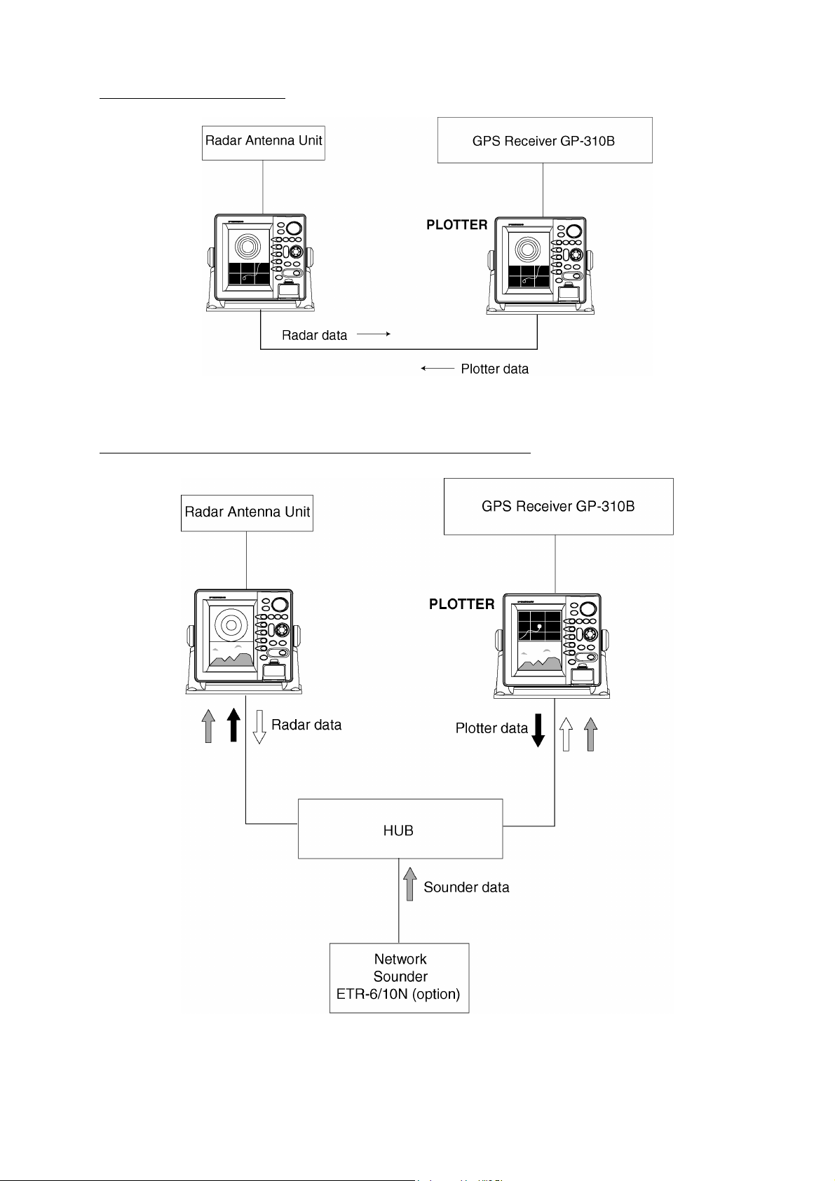
Two-unit NavNet system
Two-unit NavNet system
Three-or-more-unit NavNet system (Max. 3 display units)
Three-or-more-unit NavNet system
v
Page 8

1. DISPLAY UNIT INSTALLATION
1.1 Mounting Considerations
When selecting a mounting location for the display unit keep the following in mind:
•
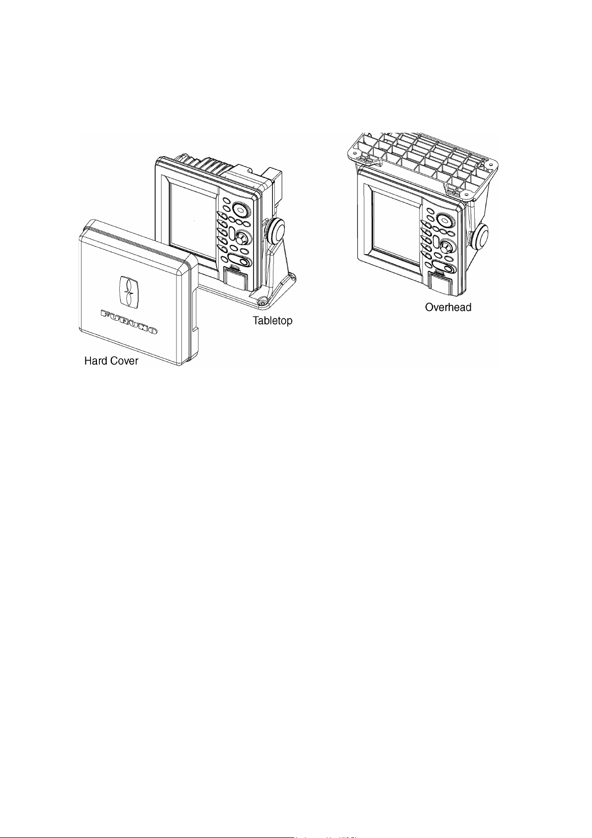
The display unit can be installed on a tabletop, on the overhead or flush mounted in a
console or panel.
•
Keep the display unit out of direct sunlight because heat can build up inside it.
•
The temperature and humidity at the mounting locat ion should be moderate and stable.
•
Locate the unit away from exhaust pipes and vents.
•
The mounting location should be well ventilated.
•
Mount the unit where shock and vibration are minimal.
•
Keep the unit away from electromagnetic field generating equipment such as a motor,
generator.
•
For maintenance and checking purposes, leave sufficient space at the sides and rear of
the unit and leave slack in cables.
•
A magnetic compass will be affected if the display unit is placed too close to it. Observe
the following compass safe distances to prevent disturbance t o t he magnetic compass:
Standard: 0.65 m, Steering: 0.45 m.
1
Page 9
1.2 Mounting
1.2.1 Tabletop and overhead mounting
Below are tabletop and overhead mounting methods.
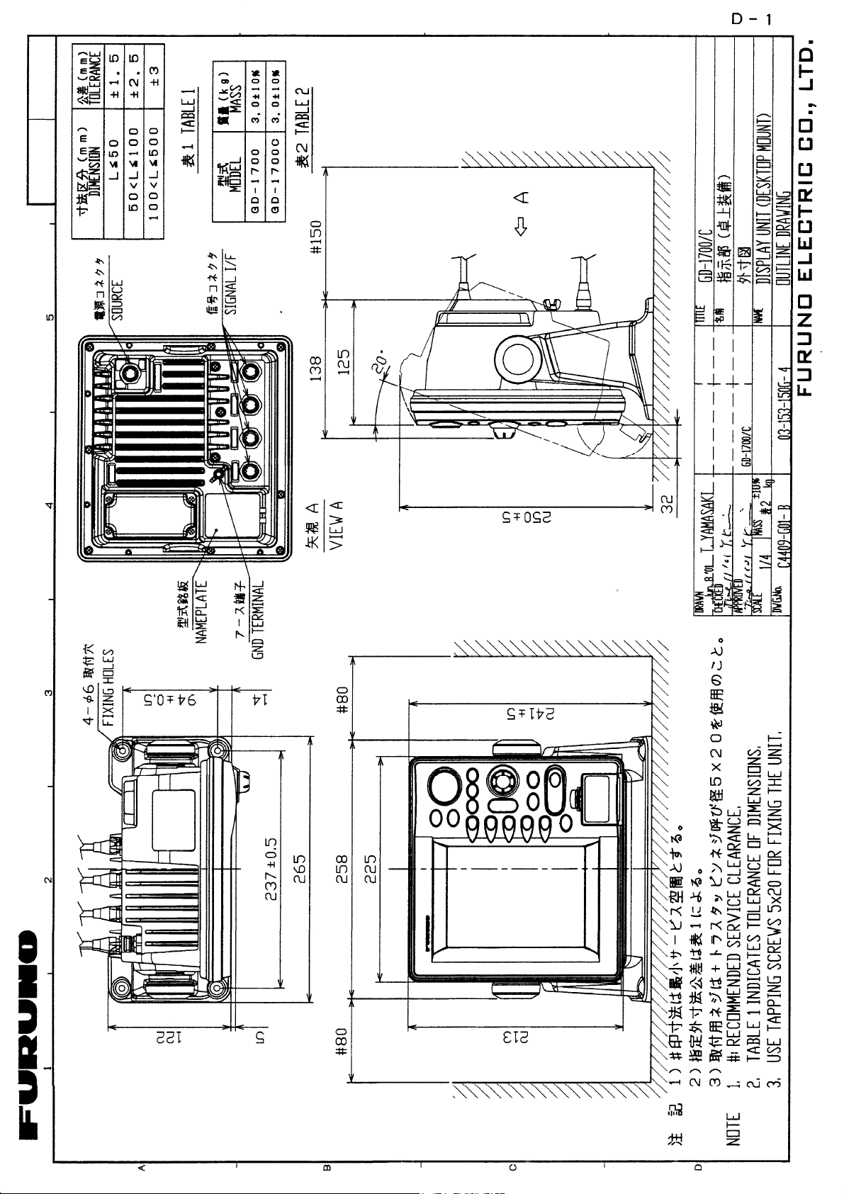
Tabletop, overhead mounting of display unit
2
Page 10
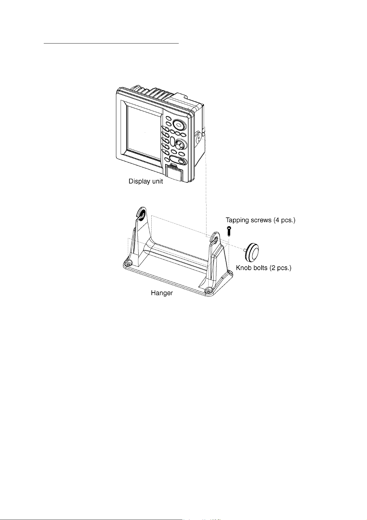
Tabletop, overhead mounting procedure
1. Fix the hanger by four tapping screws.
2. Screw knob bolts in display unit, set it to hanger, then tighten knob bolts.
3. Attach hard cover to protect LCD.
How to mount the display unit
3
Page 11
1.2.2 Flush mounting
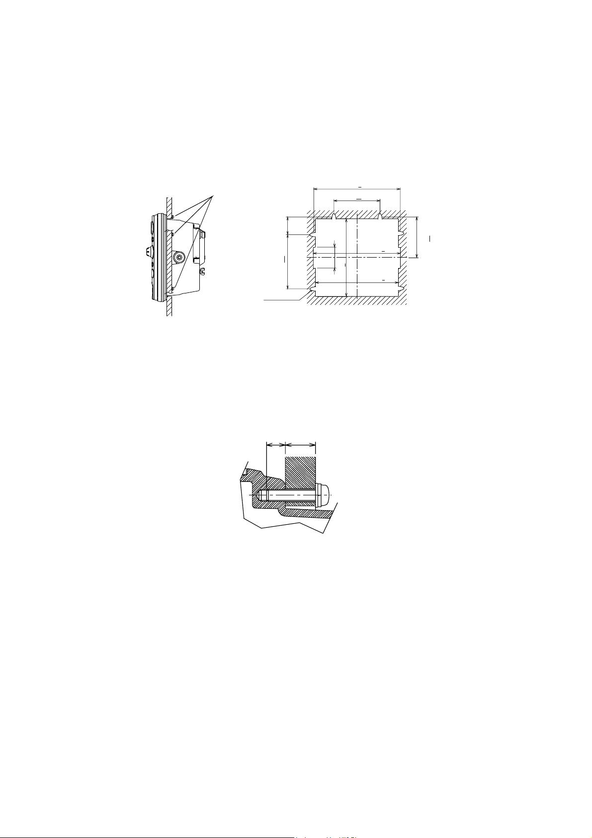
The display unit can be mounted in a panel or console, using the supplied washer head
screws.
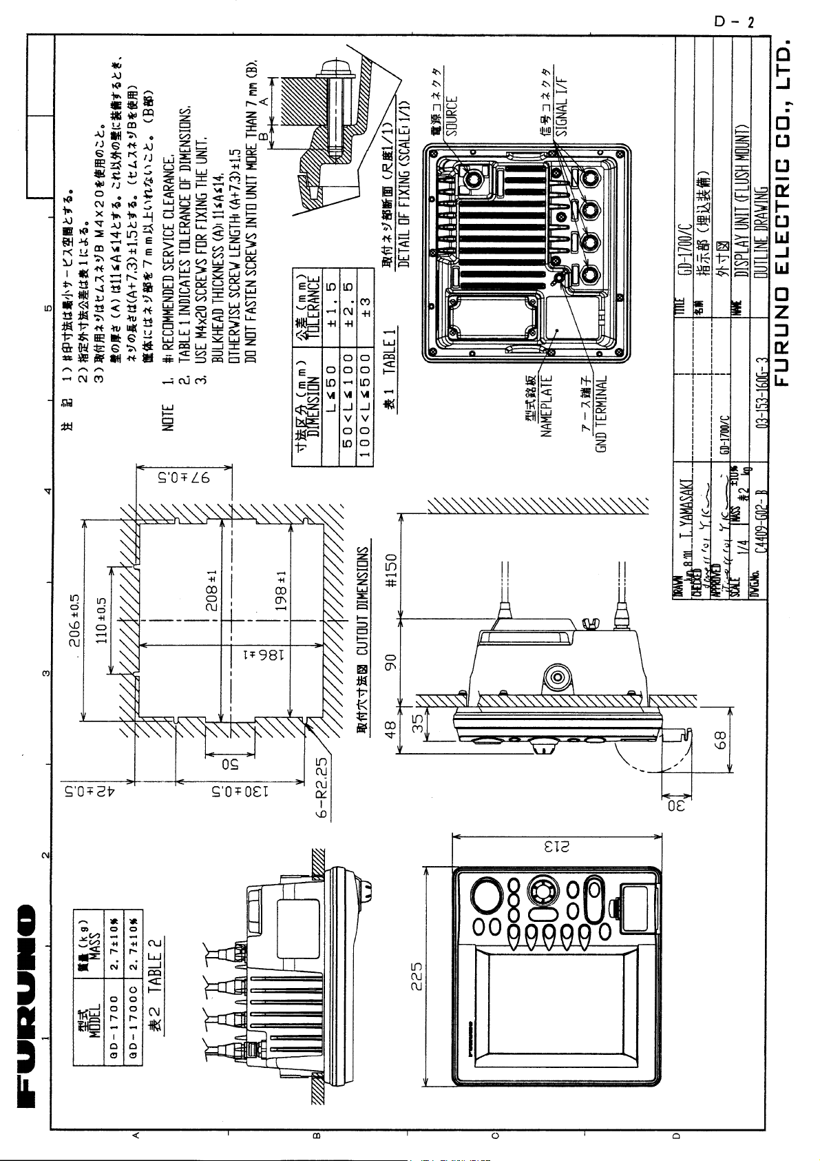
1. Prepare a cutout in the mounting location whose dim ensions are as shown below.
2. Fix the display unit with four washer head screws (M4X20).
3. Attach hard cover to protect LCD.
Washer head screws
42
130+0.5
6-R2.25
206+0.5
110+0.5
50
186+1
208+1
198+1
97+0.5
Flush mounting of display unit
Note: Use supplied washer head screws when the thickness of the bulkhead is from 11 to
14 mm. F or bulkhead which exceeds 14 mm in thickness the length of the washer
head screws (local supply) should be bulkhead thickness (“A” below) plus 7.3±1.5
mm. Also the length of “B” in the figure below should be m ax. 7 mm.
B
A
Fixing screw, side view
4
Page 12
2. WIRING
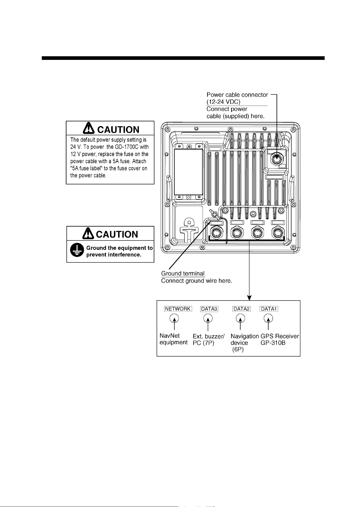
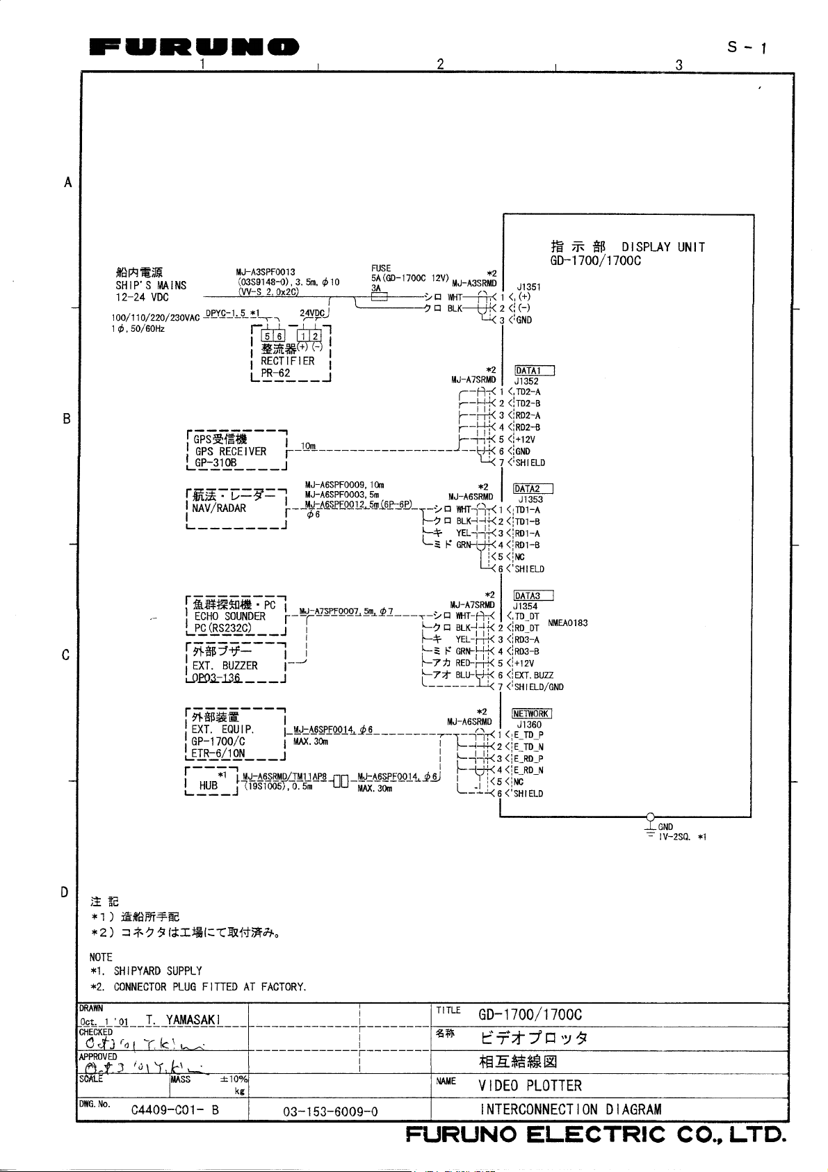
All wiring are terminated at the rear of the display unit.
Display unit, rear view
5
Page 13
2.1 Wiring
Power cable
Connect the power cable to the POWER connector. If the GD-1700C is to operate from 12
VDC power replace the power fuse with a 5A fuse (supplied) and attach the “5A fuse label”
to the fuse cover on the power cable.
Earth terminal
Connect the earth wire (local supply, IV-2sq) between the earth terminal and ship’s ground.
Data ports (DATA1 – DATA3)
External equipment may be connected to these ports as below.
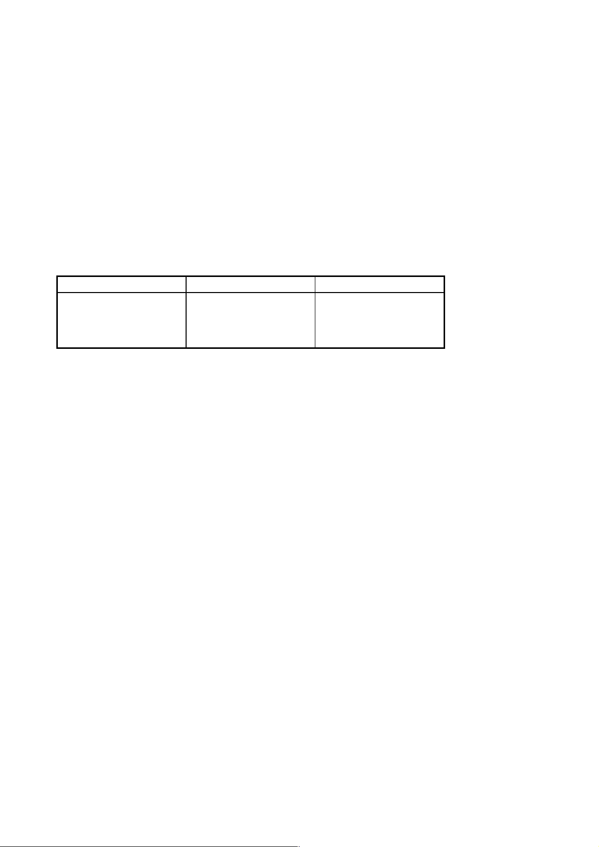
DATA1 (7P) DATA2 (6P) DATA3 (7P)
NMEA 0183 (IN/OUT)
GPS Receiver
GPS-310B, navaid,
echo sounder, etc.
NMEA 0183 (IN/OUT)
Navaid, radar, etc.
NMEA 0183 (IN/OUT)
External buzzer,
PC, echo sounder, etc.
This equipment can receive the following NMEA 0183 format sentences from external
equipment.
• Own ship’s position: GGA>RMC>RMA>GLL
• Ship’s speed: RMC>RMA>VTG>VHW
• External waypoint: RMB>WPL>BWR>BWC
• Heading (True): HDT>HDG>HDM>VHW
• Heading (Magnetic): HDM>HDG>HDT>VHW
• Course: RMC>RMA>VTG
• Depth: DPT>DBT (>DBS>DBK)
• Temperature: MTW
• Time : ZDA
• Other ship’s information: TTM
• Insight satellite information: GSV
• Beacon receiving information: MSS
• Target L/L: TLL
You will need the optional NMEA cable to connect with other equipment.
6
Page 14
Connecting GP-310B to DATA2 port
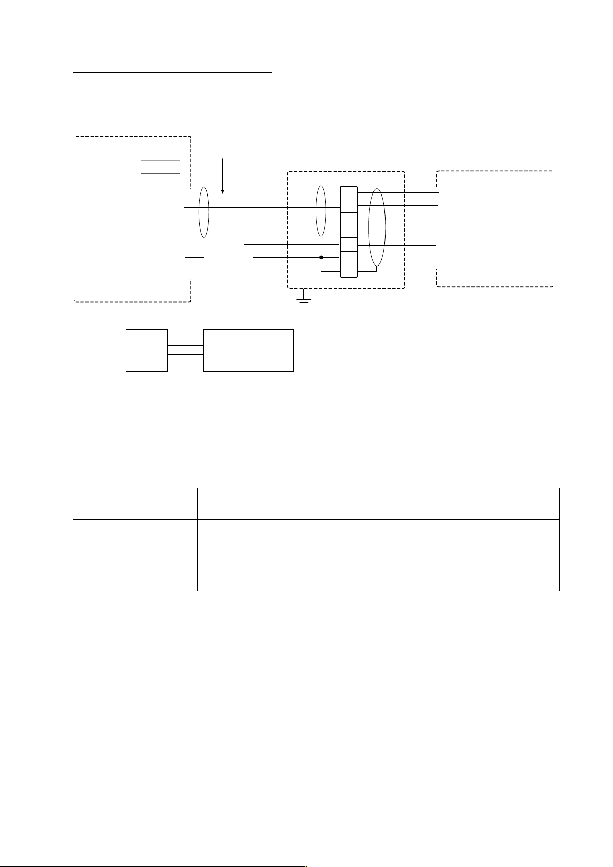
The GPS Receiver GP-310B is usually connected to the DATA 1 port, however it may also
be connected to the DATA 2 port as shown below. A junction box and optional cable
MJ-A6SPF0003-050 or MJ-A6SPF0009-100 are required.
DISPLAY UNIT
DATA 2
NC
1
2
3
4
5
6
TX-A
TX-B
RX-A
RX-B
SHIELD
Ship's
mains
NETWORK port
MJ-A6SPF0003-050
MJ-A6SPF0009-100
JUNCTION BOX
WHT
BLK
YEL
GRN
0 V
+ 12 V
Power supply
DC/DC CNV
Type: Insulation
1
2
3
4
5
6
7
How to connect GP-310B to DATA 2 port
WHT
BLU
YEL
GRN
RED
BLK
GP-310B
+12V
GND
Other NavNet equipment should be connected to the NETW ORK port, with the optional
NavNet cable. Available equipment are shown below.
Radar Plotter
Network
Sounder
Other
MODEL1722/1732/
1742/1762/1722C/
1732C/1742C/1762C/
1833/1933/1943/
GD-1700/1700C/
1900C
ETR-6/10N
HUB (used when more than
two NavNet units are
connected.)
1833C/1933C/1943C
7
Page 15
External buzzer OP03-136 (option)
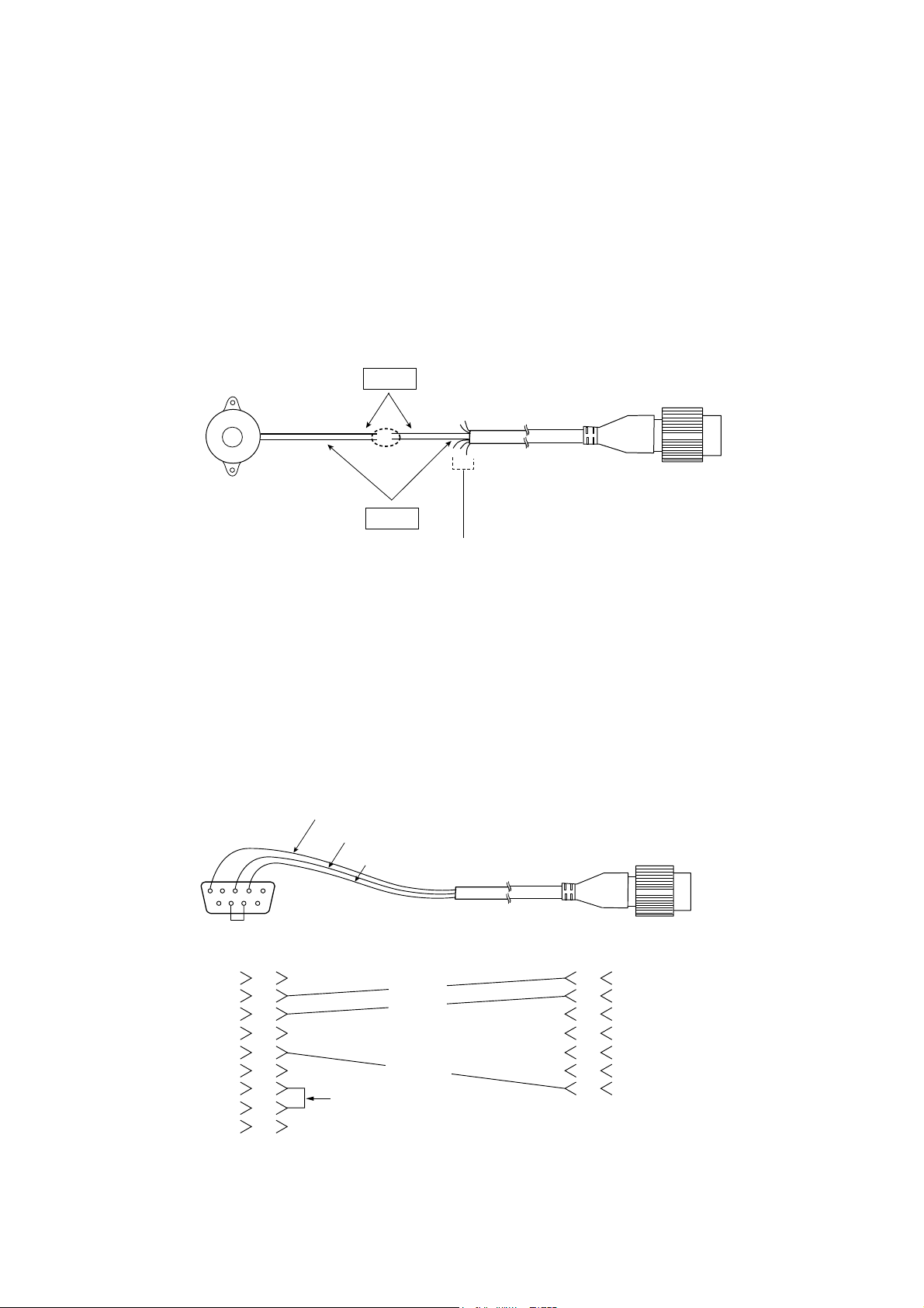
The optional external buzzer provides a louder alert when the guard alarm is violated. You
will need the external buzzer kit (Type OP03-136, Code no. 000-086-443).
Further, you will need the optional cable assy MJ-A7SPF0007-050 (w/7P connector, 5 m,
code no. 000-144-418).
1. Attach the MJ-A7SPF0007-050 cable assy (option) to the DATA 3 port at the rear of the
display unit.
2. Shorten the XH connector of the external buzzer cable with appropriate length.
3. Solder the cables made at step 2 with MJ-A7SPF0007-050 cable as shown below.
Red
Soldering
External buzzer
MJ-A7SPF0007-050
Black
Cut other wires and tape.
Connection of external buzzer
4. Fasten the buzzer with the double-sided tape or two tapping screws (3X15 or 3X20,
local supply).
2.2 How to Connect a PC
To connect a pc, prepare the optional cable assy MJ-A7SPF0007-050 and D-sub 9 pins
plug (local supply) and connect them as follows.
SHIELD
BLUE
WHITE
5
1
69
D-SUB 9PIN
RI
1
2
3
4
5
6
7
8
9
CD
RD
TD
DTR
GND
DSR
RTS
CTS
WHITE
BLUE
SHIELD
short
MJ-A7SPF0007-050
1
TD
2
RD
3
RD_A
4
RD_B
5
+12V
6
EXT BUZZ
7
GND
How to modify cable assy. MJ-A7SPF0007-050 for connection of pc
8
Page 16
3. INITIAL SETTINGS
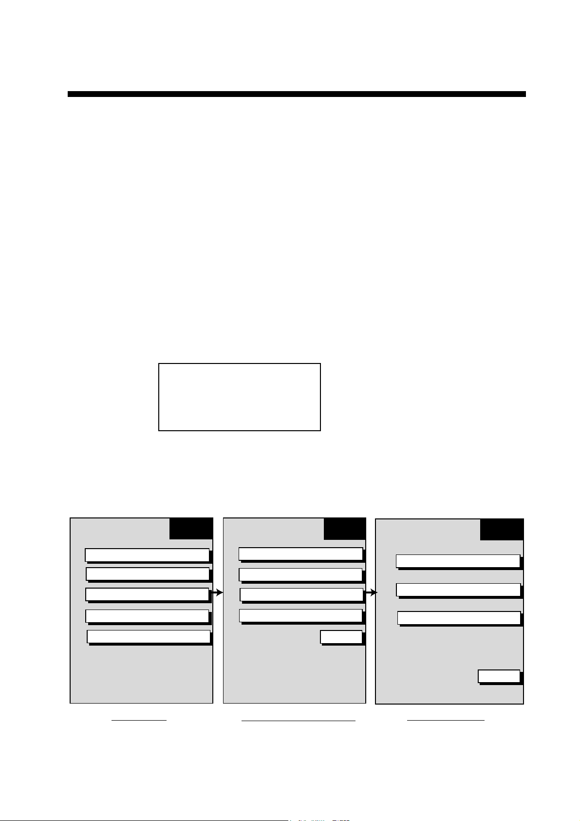
The equipment is set up f r om the installation menu, which you may access as below.
3.1 How to Access the Installation Menu
This paragraph shows you how to access the installation menus, which you will need to do
to set up the equipment.
1. Press the [POWER/BRILL] key with a touch-and-release action while pressing and
holding down the [MENU] key. Release the [POWER/BRILL] key when you hear a beep.
2. Release the [MENU] key when the message “STARTING INSTALLATION MODE”
appears.
Note: You are asked if you want to start t he simulation mode, which provides simulated
operation of the equipment, the first time you turn on the power or you turn on the
power after clearing the memory. Push the [ENTER] knob to start the simulation
mode, or press the [CLEAR] key to start normal operation. For further details
about the simulation mode, see the operator’s manual.
START
SIMULATION MODE?
YES ... PUSH ENTER KNOB
NO ... PUSH CLEAR KEY
TO SKIP.
3. Press any key twice to show the plotter screen.
4. Press the [MENU] key followed by the SYSTEM CONFIGURATION soft key to show the
SYSTEM CONFIG menu.
5. Press the INSTALLATION SET UP soft key to display the INSTALL SETUP menu.
* = Not used.
PLOTTER
MENU
CHART SETUP
PLOTTER SETUP
WAYPOINTS/ROUTES
FUNCTION KEY SETUP
SYSTEM CONFIGURATION
GENERAL SETUP
NAV OPTION
SYSTEM SETUP
INSTALLATION SETUP
SYSTEM
CONFIG
RETURN
INSTALL
SETUP
NETWORK SETUP
RADAR SETUP*
NETWORK SOUNDER SETUP
RETURN
Plotter menu
System configuration menu
Install setup menu
Menus
9
Page 17
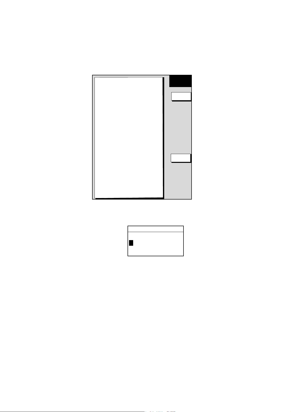
3.2 Network Setup
Complete the procedure below if other NavNet equipment is connected.
1. Open the INSTALL SETUP menu.
2. Press the NETWORK SETUP soft key.
▲
IP ADDRESS
172.031.014.001
HOST NAME
PLOTTER
RADAR SOURCE
RADAR
CHART SOURCE
--------
--------
--------
SOUNDER SOURCE
SOUNDER
SUBNET MASK
255.255.000.000
GATEWAY ADDRESS
000.000.000.000
OFFSET PORT NUMBER
10000
-
---
-
NETWORK
SETUP
EDIT
RETURN
Network setup menu
3. Select menu option and press the EDIT soft key. For example, select HOST NAME.
HOST NAME
PLOTTER_
Host name window
4. Use the cursor pad to select location and rotate t he [ENTER] knob to set alphanumeric
character.
5. Press the ENTER soft key to finish.
6. Repeat steps 3-5 for other items, referring to t he table on the next page for details.
7. Press the [MENU] key to finish.
10
Page 18
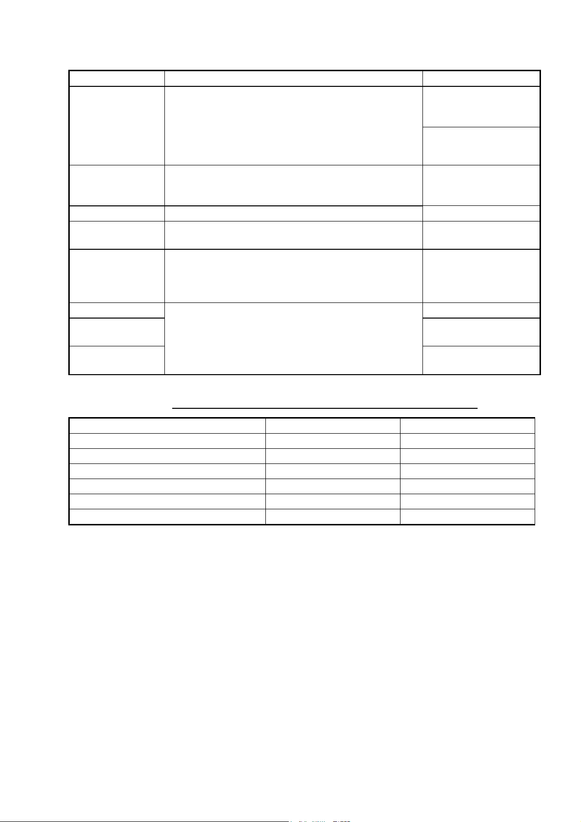
Item Description Default Setting
IP ADDRESS
HOST NAME
RADAR SOURCE Enter name of radar source. RADAR
CHART SOURCE
SOUNDER
SOURCE
SUBNET MASK 255.255.000.000
GA TEWAY
ADDRESS
OFFSET PORT
NUMBER
This address is assigned at the factory. Change the
address (last three digits; 001 to 254) when like
models are connected directly or through the hub. Do
this before connecting this equipment to other
equipment or hub to distinguish them. Do not set the
same IP address for multiple equipment.
Set the name for your display unit to distinguish it from
others in the NavNet system. Be sure not to use the
same name as other NavNet equipment.
Enter name of equipment which is to function as the
chart source. (Max. three units, excluding own.)
Enter the host name of the network sounder
ETR-6/10N to use for the video sounder display. Erase
the host name, with the [CLEAR] key, when no
network sounder is connected.
Not used. Reserved for future use.
Monochrome:
172. 031. 014. 001
Color:
172. 031. 014. 001
PLOTTER
None
SOUNDER
000.000.000.000
10000
NavNet equipment IP address and host name default settings
Model IP ADDRESS HOST NAME
MODEL1722/1732/1742/1762 172.031.003.004 RADAR
MODEL1722C/1732C/1742C/1762C 172.031.003.001 RADAR
MODEL1833C/1933C/1943C 172.031.003.003 RADAR
MODEL1833/1933/1943 172.031.003.002 RADAR
GD-1900C 172.031.003.003 PLOTTER
GD-1700C/GD-1700 172.031.014.001 PLOTTER
11
Page 19
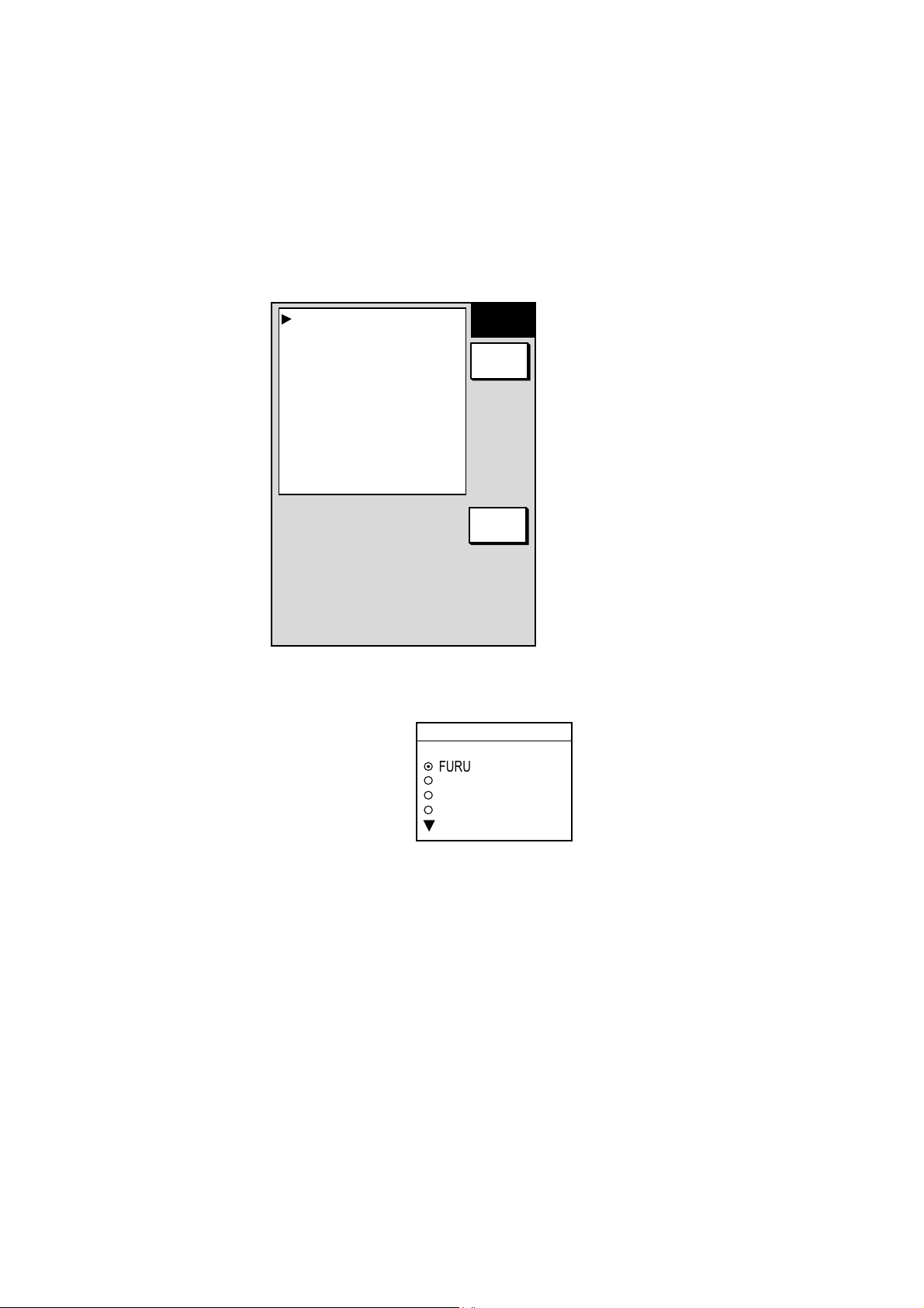
3.3 Navigation Data Source
The NAV SOURCE SETTINGS menu mainly selects the source of nav data. For navigator
other than the FURUNO GP-310B, speed averaging and local time offset (to use local time
instead of UTC time) are also available from this menu.
1. Press the [MENU] key.
2. Press the SYSTEM CONFIGURATION, NAV OPTION and NAV OPTION soft keys to
display the NAV SETUP menu.
POSITION SOURCE
ALL
SPEED AVERAGING*
0000
LOCAL TIME OFFSET*
+00:00
NAV
SETUP
EDIT
* For GPS receiver other
than GP-310B.
RETURN
Nav setup menu
3. Select POSITION SOURCE and press the EDIT soft key.
POSITION SOURCE
▲
¤
FURUNO BB GPS
¡
GP
¡
LC
¡
ALL
▼
Position source window
4. Select FURUNO BB GPS, GP, LC or ALL as appropriate and press the ENTER soft key.
FURUNO BB GPS: GPS Receiver GP-310B
GP: GPS navigator (via NETWORK, DATA 1 or DATA 2 port)
LC: Loran C (via NETWORK, DATA 1 or DATA 2 port)
ALL: Multiple navaid connection (via NETWORK, DATA 1 or DATA 2 port)
5. For GPS receiver other than the GP-310B you may adjust speed averaging and use
local time as follows:
a) Choose desired item and press the EDIT soft key.
b) Use the cursor pad to select location and rotate the [ENTER] knob to set value. For time,
use the +<− −>− soft key to switch from plus to minus and vice versa.
c) Press the ENTER soft key.
12
Page 20

Speed Averaging: Calculation of ETA is based on average ship’s speed over a given
period. If the period is too long or too short calculat ion error will result. Change this
setting if the ETA readout seems wrong. The range of adjustment is 0-9999(sec).
Local Time Offset: GPS uses UTC time. If you would rather use local time enter the
time difference between it and UTC. The range of offset is –13:30 to +13:30 and the
default setting is zero (no offset).
6. Press the RETURN soft key followed by the [MENU] key to finish.
13
Page 21
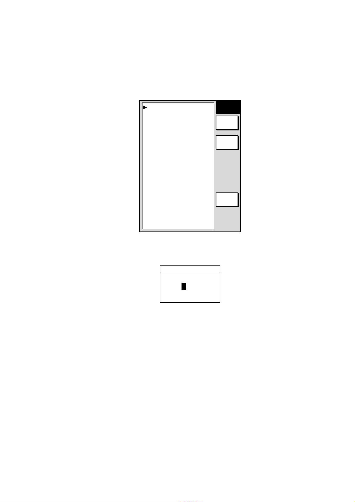
3.4 Setting up GPS Receiver GP-310B
Set up the GPS Receiver GP-310B as follows:
1. Press the [MENU] key.
2. Press the SYSTEM CONFIGURATION, NAV OPTI ON and GPS SENSOR SETTINGS
soft keys.
LOCAL TIME OFFSET
+00:00
GEODETIC DATUM
WGS-84
POSITION SMOOTHING
000 second(s)
SPD/CSE SMOOTHING
005 second(s)
GPS SPEED AVERAGING
060 second(s)
LATITUDE OFFSET
0.000’N
LONGITUDE OFFSET
0.000’E
DISABLE SATELLITE
_ _ _ _ _ _
LATITUDE
45°35.000’ N
LONGITUDE
125°00.000’ W
ANTENNA HEIGHT
005 m
GPS FIX MODE
2D/3D
COLD START
NO
GPS setup menu
3. Select ANTENNA HEIGHT and press the EDIT soft key.
ANTENNA HEIGHT
GPS
SETUP
EDIT
GPS
STATUS
RETURN
0 05 m
Antenna height window
4. Enter the height of the GPS ant enna unit above sea surface. Use the cursor pad to select
digit and rotate the [ENTER] knob to set value. The default height is 5 m.
5. Press the ENTER soft key.
6. Choose and set other items as appropriate, referring to Chapter 5 of the operat or’s
manual.
7. Press the [MENU] key to close the menu.
14
Page 22
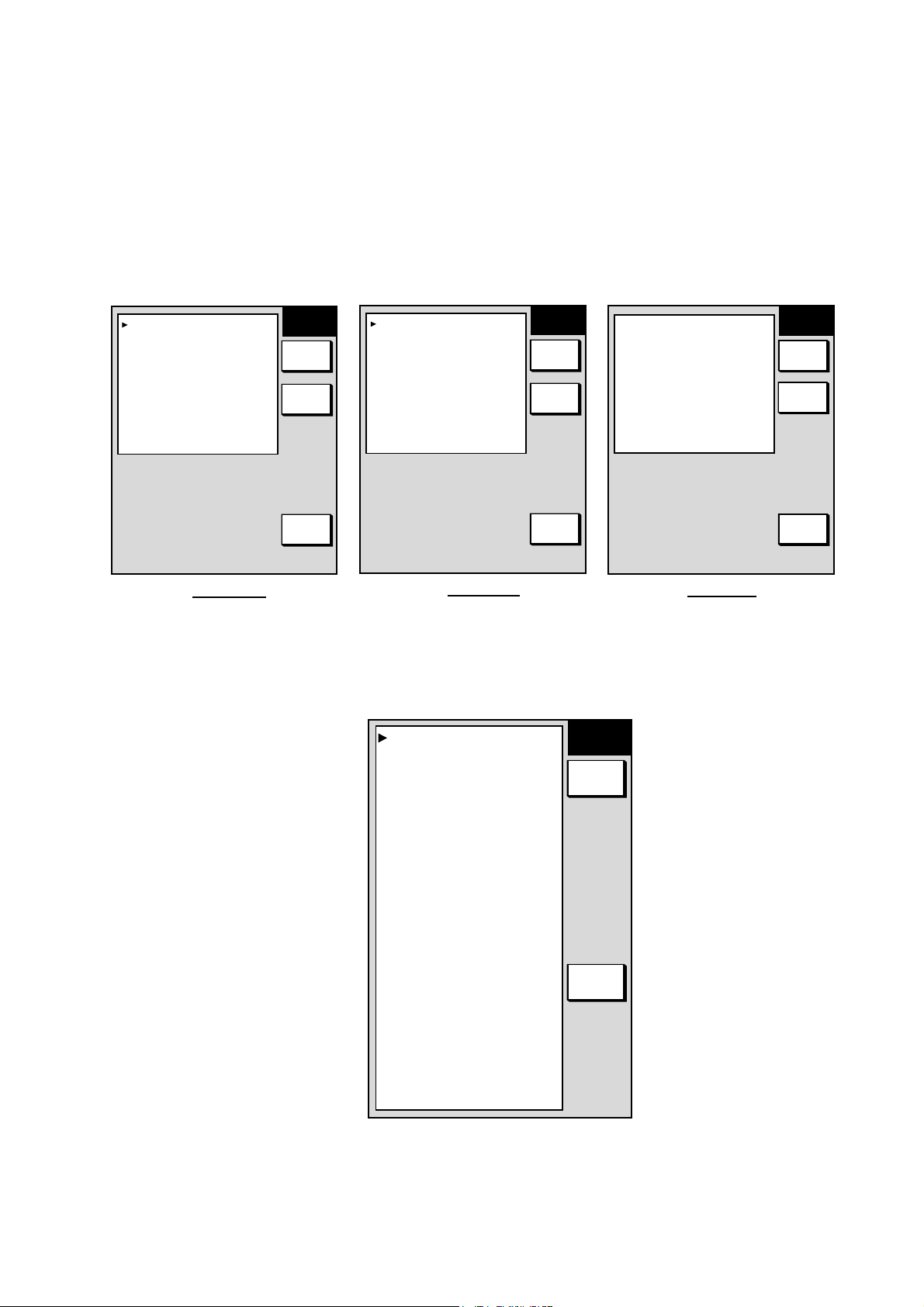
3.5 Setting up Data Ports
Setup the data ports according to the equipment connected to them as follows.
1. Press the [MENU] key to open the menu.
2. Press the SYSTEM CONFIGURATION, SYSTEM SETUP and PORT SETUP soft keys.
3. Press the GPS/NMEA PORT soft key for DATA 1 port, NMEA PORT soft key for DATA 2
port or PC/NMEA/EXT. BUZZ PORT soft key for DATA 3 port as appropriate. One of the
following displays appear depending on your selection.
FURUNO GP
OUTPUT FORMAT
LAT/LON FORMAT
OUTPUT DESTINATION
WIRING INFORMATION
TD-A >1>---WHITE
TD-B >2>---BLUE
RD-A >3>---YELLOW
RD-B >4>---GREEN
+12V >5>---RED
GND >6>---BLACK
FG >7>---SHIELD
S SENSOR
NO
NMEA0183 Ver. 2.0
DD˚ MM.MMM'
NO
PORT 1 port
GPS/
PORT
EDIT
SELECT
SNTNC
RETURN
FURUNO GP
OUTPUT FORMAT
LAT/LON FORMAT
OUTPUT DESTINATION
WIRING INFORMATION
TD-A >1>---WHITE
TD-B >2>---BLUE
RD-A >3>---YELLOW
RD-B >4>---GREEN
NC >5>--FG >6>---SHIELD
S SENSOR
NO
NMEA0183 Ver. 2.0
DD˚ MM.MMM'
NO
PORT 2 port
NMEA
PORT
EDIT
SELECT
SNTNC
RETURN
▲
NMEA OUTPUT FORMAT
NMEA Ver. 2.0
BAUD RATE
BIT LENGTH
STOP BIT
PARITY
(CONTROL: Xon/Xoff)
WIRING INFORMATION
TxD >1>---WHITE
RxD >2>---BLUE
RD-A >3>---YELLOW
RD-B >4>---GREEN
+12V >5>---RED
EXT BUZZ >6>---BLACK
GND >7>---SHIELD
4800 bps
8 bits
1 bit
NONE
PORT 3 port
GPS/NMEA, NMEA and PC/NMEA/EXT. BUZZ port setup menus
4. Select item and press the EDIT soft key.
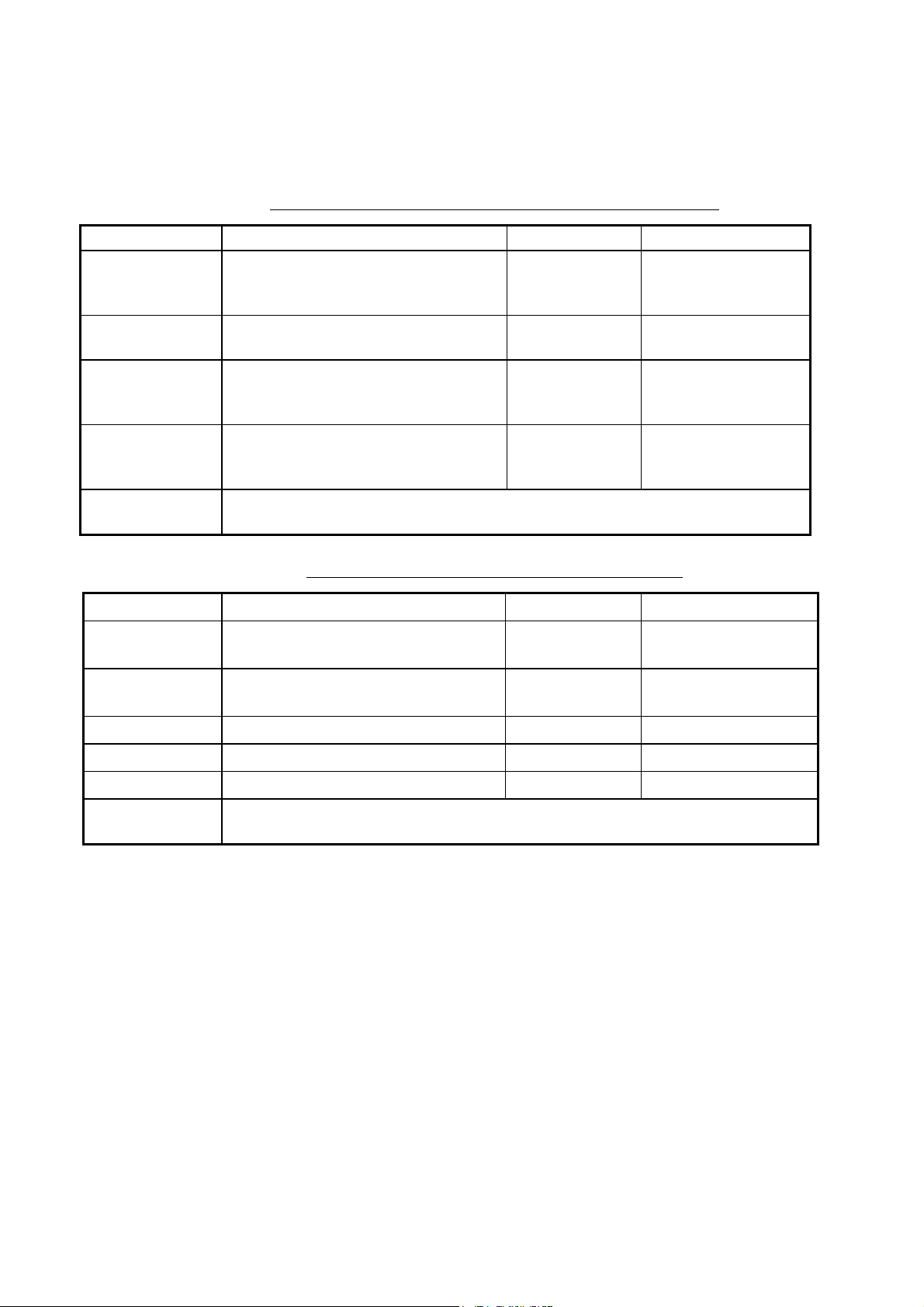
5. Set option referring to the tables on pages 16 and 17.
6. To select NMEA data sentences to output, press the SELECT SNTNC soft key.
AAM
APB
BOD
BWR#
DPT*
GGA
GLL
GTD
MTW
RMA
RMB
RMC
VHW
VTG
WPL
XTE
ZDA
HDT
HDG
MWV
TTM
--
ON
--
ON
--
--
ON
--
--
-ON
ON
-ON
--
-ON
--
--
--
--
SELECT
SNTNC
ON/OFF
RETURN
NMEA
PORT
EDIT
SELECT
SNTNC
RETURN
# = BWR for rhumb line, BWC for great circle
* = DBT for NMEA 0183 Version No. 1.5
Data sentences for NMEA 0183 version no. 2
15
Page 23
7. Select sentence and press the ON/OFF soft key to show ON (output) or “ - - “ (no
output) as appropriate.
8. Press the ENTER soft key.
9. Press the RETURN soft key followed by the [MENU] key to finish.
Contents of GPS/NMEA PORT and NMEA PORT menus
Item Description Settings Default Setting
FURUNO GPS
Sensor
Output Format
Lat/Lon Format Selects latitude/longitude format to output.
Output Destination
SELECT SNTNC
soft key
Selects whether the GPS Receiver
GP-310B is connected to the GPS/NMEA
port or not.
Selects NMEA output version of GPS
sensor.
Selects whether to output route (data
sentence RTE) and waypoint data (data
sentence WPL) when destination is set.
Selects data sentence(s) to output. Select sentence with the cursor pad and press the
ON/OFF soft key to show ON or “- -“ (OFF) as appropriate.
Yes, No No (both ports)
NMEA Ver. 1.5,
NMEA Ver. 2.0
DD°MM.MM’,
DD°MM.MMM,
DD°MM.MMMM’
Yes, No No
NMEA Ver. 2.0
DD°MM.MMM’
Contents of PC/NMEA/EXT. BUZZ PORT menu
Item Description Settings Default Setting
NMEA Output
Format
Selects NMEA output format for PC.
NMEA Ver. 1.5,
NMEA Ver. 2.0
NMEA Ver. 2.0
Baud Rate Sets baud rate.
Bit Length Sets character length. 8 bits, 7 bits 8 bits
Stop Bit Sets number of stop bits. 1 bit, 2 bits 1 bit
Parity Sets parity bit. Even, Odd, None None
SELECT SNTNC
soft key
Selects data sentence(s) to output. Select sentence with the cursor pad and press the
ON/OFF soft key to show ON or “- -“ (OFF) as appropriate.
4800, 9600,
19200 (bps)
4800(bps)
16
Page 24
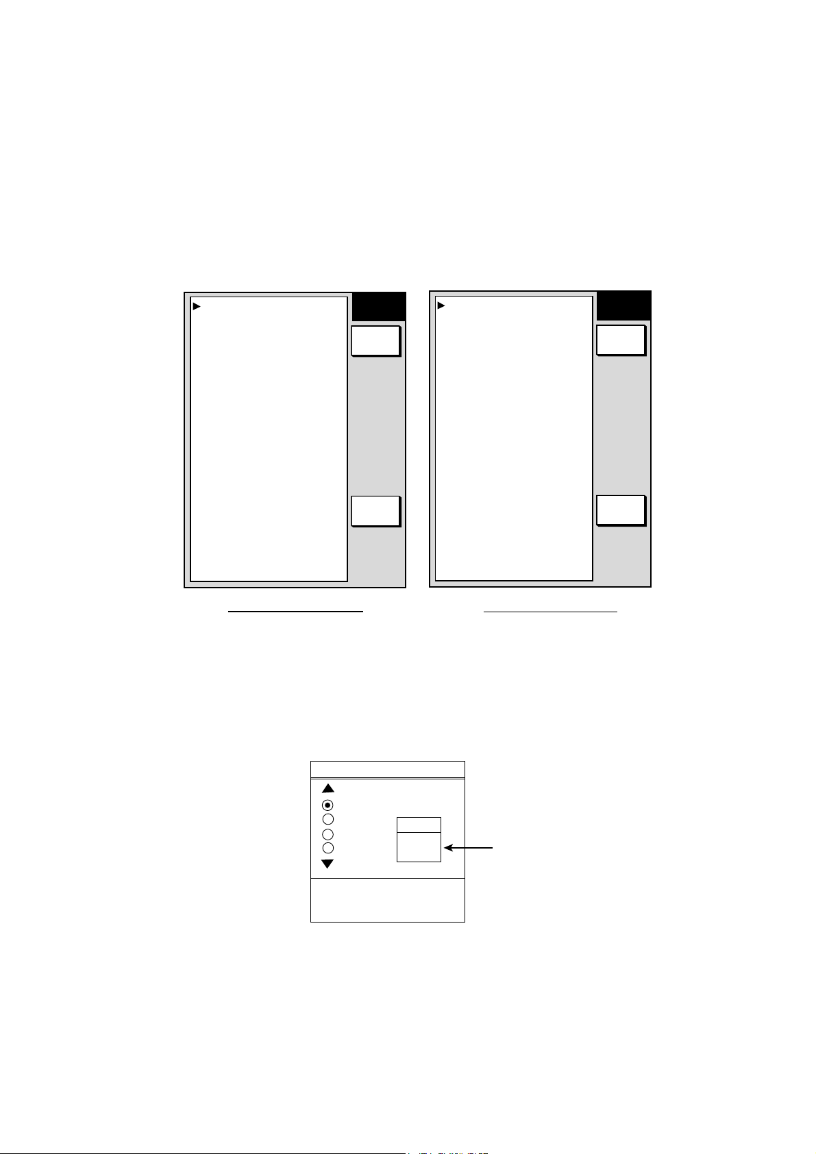
3.6 Remote Controller Setting
A remote controller can be set exclusively for use with a specific display unit, in the case of
multiple NavNet display units. Set the remote controller mode desired on t he menu and
attach appropriate label (supplied with accessories) to the remote controller and display
unit.
1. Press the [MENU] key, followed by SYSTEM CONFIGURATION soft key and
GENERAL SETUP soft key to show the GENERAL SETUP menu.
2. Press the NEXT PAGE soft key.
LAT/LON DISPLAY
DD° MM.MMMM'
TD DISPLAY
LORAN C
SPEED
SOG
POSITION DISPLAY
LAT/LON
TIME DISPLAY
24 HOURS
INFRARED REMOTE MODE
A
RANGE & BEARING MODE
RHUMB LINE
BEARING READOUT
MAGNETIC
MAGNETIC VARIATION
AUTO 00.0° E
Page 2 (GD-1700C)
GENERAL
SETUP2
EDIT
PREV.
PAGE
LAT/LON DISPLAY
DD° MM.MMMM'
TD DISPLAY
LORAN C
SPEED
SOG
POSITION DISPLAY
LAT/LON
TIME DISPLAY
24 HOURS
INFRARED REMOTE MODE
A
RANGE & BEARING MODE
RHUMB LINE
BEARING READOUT
MAGNETIC
MAGNETIC VARIATION
AUTO 00.0° E
DAY/NIGHT
DAY
Page 2 (GD-1700)
GENERAL
SETUP2
EDIT
PREV.
PAGE
GENERAL SETUP menu, page 2
3. Select INFRARED REMOTE MODE, then press t he EDI T soft key to show the I/R
REMOTE MODE window.
4. Point the remote controller toward the display unit, and press any key on the remote
controller. The remote controller mode appears in the MODE window. In the example
below the remote controller mode is “A.”
I/R REMOTE MODE
A
B
C
D
MODE
A
Remote controller
mode window
PRESS '0' AND '2'
KEY TOGETHER
TO CHANGE MODE.
I/R REMOTE MODE window
5. Press the [0] and [2] keys together on the remote controller to change the remote
controller mode setting among A, B, C and D.
6. Operate the cursor pad to set the same display mode for t he display unit as you did for
the remote controller.
7. Press the ENTER soft key, then press the [MENU] key to close the menu.
17
Page 25
Page 26
Page 27
Page 28
Page 29
Page 30
 Loading...