


9-52 Ashihara-cho,9-52 Ashihara-cho,
A
A
*00080834300**00080834300*
*00080834300**00080834300*
*OME43920F00**OME43920F00*
Nishinomiya, JapanNishinomiya, Japan
Telephone :Telephone : 0798-65-21110798-65-2111
Telefax :Telefax : 0798-65-42000798-65-4200
Your Local Agent/DealerYour Local Agent/Dealer
ll rights reserved.
ll rights reserved.
PUB.No.PUB.No. OME-43920OME-43920
(( YOSHYOSH ))
GD/GP-3300GD/GP-3300
Printed in JapanPrinted in Japan
FIRST EDITION :FIRST EDITION :AUG.AUG. 19981998
F :F : JUL.JUL. 22,200222,2002
* 0 0 0 8 0 8 3 4 3 0 0 ** 0 0 0 8 0 8 3 4 3 0 0 *
*OME43920F00**OME43920F00*
* O M E 4 3 9 2 0 F 0 0 ** O M E 4 3 9 2 0 F 0 0 *

SAFETY INSTRUCTIONS
WARNING
ELECTRICAL SHOCK HAZARD
Do not open the equipment.
Only qualified personnel
should work inside the
equipment.
Immediately turn off the power at the
switchboard if water leaks into the
equipment or something is dropped in
the equipment.
Continued use of the equipment can cause
fire or electrical shock. Contact a FURUNO
agent for service.
Do not disassemble or modify the
equipment.
Fire, electrical shock or serious injury can
result.
WARNING
Keep heater away from equipment.
A heater can melt the equipment’s power
cord, which can cause fire or electrical
shock.
Use the proper fuse.
Fuse rating is shown on the equipment.
Use of a wrong fuse can result in equipment
damage.
Do not place liquid-filled containers on
the top of the equipment.
Fire or electrical shock can result if a liquid
spills into the equipment.
Immediately turn off the power at the
switchboard if the equipment is emitting
smoke or fire.
Continued use of the equipment can cause
fire or electrical shock. Contact a FURUNO
agent for service.
Make sure no rain or water splash leaks
into the equipment.
Fire or electrical shock can result if water
leaks in the equipment.
iiiiiiiiiiiii
i

CAUTION
Do not use the equipment for other than
its intended purpose.
Use of the equipment as a stepping stool,
for example, can result in personal injury
or equipment damage.
No one navigation device should ever be
solely replied upon for the navigation of
a vessel.
Always confirm position against all available
aids to navigation, for safety of vessel and
crew.
A warning label is attached to the equipment. Do not remove the label. If the
label is missing or illegible, contact
a FURUNO agent or dealer.
About the TFT LCD
The TFT LCD is constructed using the
latest LCD techniques, and displays
99.99% of its pixels. The remaining 0.01%
of the pixels may drop out or blink, however this is not an indication of malfunction.
WARNING
To avoid electrical shock, do not
remove cover. No user-serviceable
parts inside.
Name: Warning Label (1)
Type: 86-003-1011-0
Code No.: 100-236-230
ii

TABLE OF CONTENTS
FOREWORD..........................................................................................................................vi
MENU TREE........................................................................................................................viii
SYSTEM CONFIGURATION........................................................................................ix
OPERATIONAL OVERVIEW
1.1 Control Description ...............................................................................................................1-1
1.2 Inserting Chart Cards.............................................................................................................1-2
1.3 Turning the Power On/Off .....................................................................................................1-3
1.4 The Trackball .........................................................................................................................1-4
1.5 The Cursor .............................................................................................................................1-4
1.6 Shifting the Display ...............................................................................................................1-5
1.7 Returning Own Ship Marker to Screen Center......................................................................1-5
1.8 Selecting Screen Center by Cursor Position..........................................................................1-6
1.9 Chart Scale.............................................................................................................................1-7
1.10 Display Brilliance and Key Backlighting............................................................................1-7
1.11 Card Drives, Chart Cards.....................................................................................................1-8
1.12 The Data Window..............................................................................................................1-12
1.13 Display Modes...................................................................................................................1-13
1.14 Menu Operation.................................................................................................................1-14
1.15 Operation on the Display...................................................................................................1-16
1.16 Operational Status Icons....................................................................................................1-17
1.17 Economy Mode .............................................................................................................. ...1-17
1.18 Plot Mode Displays ...........................................................................................................1-18
1.19 Setting the Time and Date .................................................................................................1-20
TRACK
2.1 Stopping Track Recording.....................................................................................................2-1
2.2 Track Color ............................................................................................................................2-2
2.3 Changing Color, Appearance of Specific Track ....................................................................2-2
2.4 Deleting Track .......................................................................................................................2-4
2.5 Track Plotting Interval ...........................................................................................................2-6
2.6 Customizing the Hold Function.............................................................................................2-8
2.7 Customizing the PLOT INTVL Key .....................................................................................2-9
MARKS, LINES
3.1 Entering Marks ......................................................................................................................3-1
3.2 Changing Current Mark Color...............................................................................................3-2
3.3 Changing Shape, Color of Specific Marks ............................................................................3-3
3.4 Deleting Marks ......................................................................................................................3-4
iii

3.5 External Event Mark..............................................................................................................3-5
3.6 Target Mark ...........................................................................................................................3-5
3.7 Lines ......................................................................................................................................3-5
WAYPOINTS
4.1 Entering Waypoints ...............................................................................................................4-2
4.2 Entering a Comment for a Waypoint .....................................................................................4-5
4.3 Turning Specific Waypoint Displays On/Off.........................................................................4-6
4.4 Deleting Waypoints ...............................................................................................................4-7
4.5 Destination Waypoint ............................................................................................................4-8
4.6 Cancelling Destination Waypoint ........................................................................................4-12
ROUTE NAVIGATION
5.1 Creating Routes .....................................................................................................................5-2
5.2 Following a Route .................................................................................................................5-5
5.3 Temporarily Deselecting a Route Waypoint ..........................................................................5-6
5.4 Deleting Route Waypoints .....................................................................................................5-7
5.5 Cancelling Route Navigation.................................................................................................5-8
5.6 Route Calculation ..................................................................................................................5-9
ALARMS
6.1 Arrival Alarm, Anchor W atch Alarm.....................................................................................6-1
6.2 XTE Alarm, Border Alarm ....................................................................................................6-3
6.3 Ship’s Speed Alarm ...............................................................................................................6-4
6.4 When the Alarm Buzzer Sounds............................................................................................6-5
VIDEO PILOT DISPLAY, NAVIGATION DATA DISPLAY
7.1 Video Pilot Display................................................................................................................7-1
7.2 Navigation Data Display .......................................................................................................7-4
AUTOPILOT DATA
8.1 Features Available with Autopilot Connection......................................................................8-1
8.2 Autopilot Information on Plot Display..................................................................................8-2
8.3 Autopilot Information on Video Pilot Display ......................................................................8-3
MEMORY CARD OPERATIONS
9.1 Formatting Memory Cards ....................................................................................................9-1
9.2 Saving Data to Memory Cards ..............................................................................................9-2
9.3 Playing Back Memory Cards.................................................................................................9-4
9.4 Saving, Playing Back Initial Settings ....................................................................................9-5
9.5 Editing Memory Cards ..........................................................................................................9-6
iv

GPS RECEIVER OPERATION (GP-3300)
10.1 GPS Information on the Navigation Data Display ............................................................10-1
10.2 GPS and DGPS Initial Settings .........................................................................................10-3
10.3 Satellite Force Health/Deselection ....................................................................................10-5
10.4 GPS Smoothing .................................................................................................................10-6
10.5 Cold Start........................................................................................................................... 10-8
10.6 Geodetic Datum................................................................................................................. 10-9
10.7 Correcting GPS Position.................................................................................................... 10-9
OTHER FUNCTIONS
11.1 Displaying Position in Loran TDs .....................................................................................11-1
11.2 Bearing Display Reference................................................................................................ 11-2
11.3 Magnetic Deviation ...........................................................................................................11-3
11.4 Changing Chart Appearance .............................................................................................. 11-4
11.5 Correcting Chart Position .................................................................................................. 11-5
11.6 Loran TD Correction ......................................................................................................... 11-7
11.7 Calculating R/B Between Two Points ............................................................................... 11-8
11.8 Locking Preferred Settings .............................................................................................. 11-10
11.9 Memory Capacity ............................................................................................................11-10
11.10 Apportioning the Memory ............................................................................................. 11-12
11.11 Reading Number of Track, Marks Used ........................................................................ 11-13
11.12 Smoothing...................................................................................................................... 11-14
11.13 Selecting Navaid............................................................................................................ 11-15
11.14 Track, Mark and Marker Attributes ............................................................................... 11-16
11.15 Chart Symbols, Contour Lines Attributes...................................................................... 11-19
MAINTENANCE & TROUBLESHOOTING
12.1 Preventive Maintenance ....................................................................................................12-1
12.2 Diagnostic Tests.................................................................................................................12-2
12.3 Error Messages ..................................................................................................................12-5
12.4 Replacement of Fuse .........................................................................................................12-7
12.5 Replacement of Batteries...................................................................................................12-8
12.6 Verifying Program Version No. .........................................................................................12-9
12.7 Troubleshooting Table .....................................................................................................12-10
12.8 Clearing Memories .......................................................................................................... 12-12
APPENDIX
Time Differences ........................................................................................................................ A-1
Geodetic Chart List..................................................................................................................... A-2
SPECIFICATIONS......................................................................................................... SP-1
INDEX...............................................................................................................................Index-1
Declaration of Conformity
v

FOREWORD
A Word to FURUNO GD-3300/GP-3300 Owners
FURUNO Electric Company thanks you for considering and purchasing the FURUNO GD-3300/GP-3300. We are confident you will discover why FURUNO has become synonymous with quality and
reliability.
For over 40 years FURUNO Electric Company has enjoyed an enviable reputation for efficient and dependable marine electronics equipment. This dedication to excellence is furthered by our extensive global
network of agents and dealers.
Y our unit is designed and manufactured to meet the rigorous demands
of the marine environment. However, no machine can perform to the
utmost of its ability unless properly operated and maintained. Please
carefully read and follow the recommended procedures for operation
and maintenance.
We would appreciate hearing from you, the end-user, about whether
we are achieving our purposes.
Thank you for considering and purchasing FURUNO.
vi

Features
The GD-3300 and the GP-3300 mostly share the same features. The
GP-3300 is additionally equipped with a GPS receiver and a GPS
antenna, to receive and process GPS satellite signals.
Navigation data appear on a high-resolution 10.4-inch color LCD.
Data shown are shp’s position in latitude and longitude, speed and
course, cursor position, range and bearing to cursor, range and bearing to a waypoint.
The display unit is powered by a 12 V or 24 VDC power supply.
• GP-3300 accepts connection of DGPS Beacon Receiver
• NAVIONICS chart card compatible
• Alarms: Arrival alarm, Anchor Watch alarm, Cross-track Error
alarm, Border alarm, Ship’s Speed alarm
• Large capacity memory: 8,000 points of tracks and marks, 98
waypoints, 10 routes with 15 waypoints per route
• Comprehensive navigation display of alphanumeric navigation
data plus automatic track plotting
• Economy mode reduces power consumption – LCD is turned off
while receiver/processor keeps updating data.
• Factory-digitized electronic charts on ROM cards.
• Memory cards for storage of track, waypoints, marks
• Menu-driven operation
• Navigation planning from/to waypoint or route
vii

MENU
MENU TREE
1 WAYPOINT
2 ROUTE
3 SAVE DATA TO MEMORY CARD
1 TRACK
2 MARK/LINE
3 WAYPOINT/ROUTE
4 INITIAL SETTINGS
7 DELETE MEMORY CARD DATA
8 FORMAT MEMORY CARD
9 SELECT CARD SLOT
( 1 UPPER 2 LOWER)
4 LOAD MEMORY CARD
1 TRACK
2 MARK/LINE
3 WAYPOINT/ROUTE
4 INITIAL SETTINGS
9 SELECT CARD SLOT
( 1 UPPER 2 LOWER)
5 DISPLAY MEMORY CARD
6 CORRECT POSITION
7 APPORTION/DELETE MEMORY
1 APPORTION MEMORY
2 DELETE TRACK
3 DELETE MARK
8 INITIAL SETTINGS (See below.)
9 MISC
1 EDIT TRACK/MARK
CALCULATE
2
RANGE/BEARING
6 SPECIAL
SELECT MARKS/
7
CONTOUR LINE
CLEAR
8
MEMORY
CLEAR SCREEN
1
DATA
CLEAR ALL GD
2
DATA
CLEAR GPS
3
DATA
4 CLEAR ALL DATA
INITIAL SETTINGS, page 1
INTERNAL NAV
EXTERNAL NAV
I/O DATA FORMAT
L/L SMOOTHING
PLOT INTERVAL 1
PLOT INTERVAL 2
WAYPOINT MARK
EVENT MARK
TRACK(HOLD PLOT)
LINE (HOLD PLOT)
MAGNETIC DEVIATION
BEARING
COURSE VECTOR
MARK SIZE
CURSOR SIZE
OWN SHIP MARK
TRACK WIDTH
RANGE UNIT
VTD AVG TIME
DATE
TIME
EXTERNAL CLOCK
AUTOPILOT DISPLAY
TD INDICATION
INITIAL SETTINGS, page 2 (GPS settings)
POSITION FIXING MODE
GEODETIC DATUM
HDOP THRESHOLD
TIME DIFFERENCE
LATITUDE
LONGITUDE
DELTA LATITUDE
DELTA LONGITUDE
SMOOTHING
ANTENNA HEIGHT
COLD START
CST SATELLITE NO.
MIN. ELEVATION ANGLE
DESELECT SAT NO.
D.GPS MODE
RTCM VER
BYTE FORM
FIRST BIT
PARITY BIT
STOP BIT
BIT RATE
BAUD RATES
viii
9 SELF TEST
MEMORY • I/O
1
PORT
2 KEYBOARD
TEST
3
PATTERN 1
TEST
4
PATTERN 2

GPS ANTENNA UNIT
GPA-017S
(For GP-3300)
Differential GPS
Receiver GR-80*
(GP-3300 only)
SYSTEM CONFIGURATION
GPS PLOTTER
MODE
NAV
VIDEO
MANU
PLOT
DATA
PILOT
SELECT
FR/TO WPT
ROUTE ALARM
MARK
PLOT
TRACK
CHART
COLOR
INTVL
COLOR
EVENT
C
1
L
R
CURSOR
ON/OFF
BRILL
ECONO
6325874
9
0
ZOOMINZOOM
CEN
TER
E
N
T
OUT
Navigator (for GD-3300)
Video Sounder
Radar
Autopilot
Event Switch
POWER
ON
OFF
Rectifier
PR-62
100/110/220/230 VAC
50/60 Hz
SHIP’S MAINS
10.8 - 31.2 VDC
DISPLAY UNIT
GP-3300-E/ GD-3300-E
: Option
: Connectable external equipment
* Cannot be connected to GD-3300.
ix

OPERATIONAL OVERVIEW
This chapter acquaints you with the basics of your unit – from turning on the power to entering the time and date.
1.1 Control Description
The keyboard consists of 40 logically arranged keys. The unit confirms correct key input by releasing a single beep. Invalid key input
is denoted by a series of beeps.
GPS PLOTTER
VIDEO
PLOT
PILOT
SELECT
FR/TO WPT
TRACK
CHART
COLOR
1
ZOOMINZOOM
CURSOR
ON/OFF
BRILL
ECONO
MODE
DATA
ROUTE ALARM
PLOT
INTVL
0
CEN
TER
NAV
MANU
MARK
COLOR
EVENT
C
L
R
6325874
9
E
N
T
OUT
Keyboard
POWER
ON
OFF
Power switch
Figure 1-1 Display unit
Trackball
Card slot
Memory card (upper)
Electronic chart card (lower)
1-1

lortnoC/yeKnoitcnuF
TOLP .syalpsidatadffo/nonrutotsnoitcnufoslA.yalpsidtolpstceleS
TOLIPOEDIV .syalpsidatadffo/nonrutotsnoitcnufoslA.yalpsidtolipoedivstceleS
ATADVAN.yalpsidatadnoitagivanstceleS
UNEM .neercssuoiverpsyalpsid;unemsesolc/snepO
OT/RF.tniopyawnoitanitsedslecnac/steS
TPW.stniopyawsretsigeR
ETUOR.setuorsretsigeR
MRALA.unemmralasyalpsiD
TRAHC .trahccinortceledezitigid-yrotcaffosetubirttasegnahC
ROLOCKCART.rolockcartsegnahC
LVTNITOLP .kcartgnidrocerspotsrolavretnitolpastcelessserphcaE
ROLOCKRAM.rolockramsegnahC
TNEVEdnasyeKKRAM nehwrotagivanotnoitisops’pihsstuptuO:TNEVE(.enil/kramsretnE
syeKciremuN.atadciremunretnE
RLC secnelis;tniopyawrokramseteled;atadfoenileritnenasraelC
TNE.tupnidraobyeksetanimreT
]+[ tniopyawnosnrut;tsaErohtroNotetanidroocedutitalsegnahC
]-[ tniopyawffosnrut;tseWrohtuoSotetanidroocedutignolsegnahC
FFO/NOROSRUC.ffo/norosrucsnruT
NIMOOZ
TUOMOOZ
RETNEC .retnecneercsotrosruc/rekrampihsnwosnruteR
syeKworrA.rosrucdnayalpsidtfihS
ONOCELLIRB otsnoitcnufoslA.gnithgilkcabdraobyekdnaecnaillirbneercsstsujdA
T able 1-1 Control description
).desserp
.mralaelbidua
.stniopetuorstceles;yalpsid
.stniopetuorstcelesed;yalpsid
.elacstrahcegnahC
.egapsllorcs;)sDTnaroLroL/L(dohtemnoitacidninoitisopsegnahC
:etoN ".yekegnahC"sasyalpsidunemnosraeppayeksihT
DCLehtlitnunwoddlohdnasserp(edomymonoceehtffo/nonrut
.)ffosnrut
1.2 Inserting Chart Cards
Normally, insert appropriate chart card before turning on the power.
1. Open the card drive cover.
Figure 1-2 Opening chart slot
1-2

2. Insert the electronic chart card which contains a chart of your sea
area into the lower card drive.
Figure 1-3 Inserting chart card
Note: Always close the card drive cover to keep humidity and water
out of the drive.
1.3 Turning the Power On/Off
Turning the power on
Press the [POWER] switch at bottom left-hand side of the unit. You
will hear a “peep” when turning on the power. To turn off the power
press the switch again.
After turning on the power the display changes in the sequence illustrated in Figure 1-4. About 20 seconds later accurate own ship’ s position is displayed in case of the GP-3300.
GPS PLOTTER
POWER
ON
OFF
Power switch
CHART
CURSOR
ECONO
PLOT
FR/TO WPT
1
ON/OFF
BRILL
MODE
NAV
VIDEO
DATA
PILOT
SELECT
ROUTE ALARM
PLOT
TRACK
INTVL
COLOR
6325874
9
0
ZOOMINZOOM
CEN
TER
MANU
MARK
COLOR
EVENT
C
L
R
E
N
T
OUT
Figure 1-4 GD-3300/GP-3300
For the GP-3300, at the first power application after installation, it
takes about two minutes to acquire GPS satellite data, called the almanac. While the unit is acquiring the almanac, the indication “CST”
appears at the top of the display . “CST” is replaced by “2D” or “ACQ”
after the almanac is acquired. If the vessel has moved more than 600
miles with the system turned off, reenter estimated position on the
GPS INITIAL SETTINGS menu (key sequence: [MENU], [8], [
]).
If asterisks appear instead of ship’s position data, this means there is
no navigation input. Check to make sure proper navigation aid is
selected on the INITIAL SETTINGS menu (keying sequence:
[MENU], [8]).
1-3

1.4 The Trackball
1.5 The Cursor
The main function of the trackball is to
shift the cursor and the display. The display may be shifted when the cursor is
turned off; the cursor when it is turned on.
Figure 1-5 Operating the trackball,
shifting the picture (cursor off)
The cursor functions to
• Find latitude and longitude of a location
• Find range and bearing from your ship to position selected
• Enter and erase marks, lines and waypoints
Note: Y ou can select cursor configuration (cross hairs or entire screen
cursor) on the INITIAL SETTINGS menu (keying sequence:
[MENU], [8]). The default cursor configuration is the cross hairs.
Turning the cursor on/off
Each press of the [CURSOR ON/OFF] key turns the cursor on/off.
With the cursor on, operate the trackball or the arrow keys to shift the
cursor. Use the trackball for general placement and the arrow keys
for fine tuning. The cursor moves in the direction of the trackball
moves. When the cursor reaches the edge of the display, the display
shifts in the opposite direction.
1-4
Figure 1-6 Shifting the cursor

Cursor information
Cursor position in latitude and longitude and the range and bearing
from your ship to the cursor appear in the data window at the top of
the display.
Cursor position
+36° 44.257’ N 340.5°
134° 40.719’ E 10.0KTS
Figure 1-7 Location of cursor information
1.6 Shifting the Display
The display can be shifted, when the cursor is off, by the trackball or
arrow keys. The display shifts in the direction of trackball rotation or
arrow key pressed. Note that this function is only available with
FURUNO chart cards.
40 42
Cursor
1.46NM
109.8
0.10NM
2D 1.2
°
Cursor range
Cursor bearing
1.7 Returning Own Ship Marker to Screen Center
You can return the own ship marker to the screen center by pressing
the [CENTER] key. This function is only available with FURUNO
chart cards.
1-5

1.8 Selecting Screen Center by Cursor Position
In normal usage your ship is at the screen center. This function is
only available with FURUNO chart cards.
If you want to select a land feature as the screen center, do the following:
1. Display the cursor (if it is not already displayed) by pressing the
[CURSOR ON/OFF] key.
2. Operate the trackball to place cursor on position desired.
3. Press the [CENTER] key.
CENTER
Figure 1-8 How to select screen center
1-6

1.9 Chart Scale
The chart scale can be adjusted with the [ZOOM IN] and [ZOOM
OUT] keys. Note that the [ZOOM IN] key shrinks the picture, and
the [ZOOM OUT] key “blows up” the picture. With a smaller range,
you may find that the track appears in tiers.
The horizontal range of the display in nautical miles appears at the
top right-hand corner of the Data Display. Whenever the scale is
changed the new range appears momentarily at the screen center.
Horizontal range (123.4 NM)
DATA DISPLAY (2)
34° 44.258’ N 340.5° 123.4NM
0’ 10"
134° 40.719’ E 341.2°
123.4NM
Figure 1-9 Location of chart scale indications
GPS 1.2
Horizontal range
1.10 Display Brilliance and Key Backlighting
The [BRILL ECONO] key adjusts display screen brilliance and keyboard backlighting in seven levels including off.
1-7

1.1 1 Card Drives, Chart Cards
Card drives
Two card drives are behind the card drive door: t he upper slot is for
memory cards which store display data (waypoints, tracks, and marks),
and the lower slot is for digitized chart cards.
Displaying an electronic chart with the power
turned on
Follow the procedure below to display an electronic chart with the
power turned on.
1. Open the card slot door.
Figure 1-10 Opening card slot door
2. Insert chart card label side up in the lower slot.
This side up.
FURUNO
Card
Figure 1-11 Inserting chart card
3. Close the card slot door.
4. Press [ZOOM IN] or [ZOOM OUT] key to display chart.
NAVIONICS
Card
1-8

Ejecting the chart card
Press the eject button.
Figure 1-12 Removing chart card
Care and handling of the cards
• Keep the cards away from direct sunlight, heat sources, and active
gases.
• Keep cards away from water and chemicals.
• Keep the connector free of foreign material.
• Do not drop the cards.
Chart card troubleshooting
• Chart does not disappear after removing card.
Operate [ZOOM IN] or [ZOOM OUT] key.
• Card inserted but chart does not appear.
Operate [ZOOM IN] and [ZOOM OUT] keys.
• Small island or object is not filled in (it is hollow).
Operate [ZOOM IN] and [ZOOM OUT] keys.
• Part of land on video pilot display is hollow.
Shift display.
• Land areas on a chart are hollow.
Chart overenlarged. Operate [ZOOM IN] key.
1-9

Chart icons
The display shows three different icons to alert the operator to chart
status. These are as described in Table 1-2.
Table 1-2 Chart icons
Icon Reason Displayed Remedy
• Card is not inserted
properly.
• Chart scale is too small.
• This icon means the chart is displayed properly; full
chart reliability.
• This icon means poor
chart reliability because
chart is overenlarged.
• Insert card.
• Enlarge chart by [ZOOM
IN] key.
Use chart with extreme
caution.
Shrink chart by [ZOOM
OUT] key.
FURUNO chart symbols
The table below shows FURUNO chart symbols and their meanings.
Table 1-3 FURUNO chart symbols
Symbol
Description Symbol
Description
Summit
Wreck
Lighthouse
Lighted Buoy
Buoy
Radio Station
Position of
Sounding
Obstruction
Fishing Reef
Platform
Anchorage
1-10

Comparison of FURUNO, NAVIONICS chart cards
Table 1-4 Comparison of FURUNO, NAVIONICS chart cards
metIONURUFSCINOIVAN
gnillorcstoD
ytilibapac
yalpsidpu-esruoCSEYON
youb,esuohthgiL
noitatneserpatad
rosructamooZ
noitisop
rotauqEtaegnaR,6,4,3,2,5.1,1
gniretneCSEY2*
:2*.yltcefrepderetnecebtonyamnoitisoppihsnwoehT
SEYON
ONSEY
SEY1*
mn2918...21,8
yrtneatadtesffotrahCSEYON
.deretnecebtonyamrosrucehT:1*
nacstod652ylno(
)ecnotadellorcseb
,1,5.0,52.0,521.0
mn4201...8,4,2
Buoy, lighthouse data display on NAVIONICS
charts
NAVIONICS chart cards can show buoy and lighthouse data.
1. Insert a NA VIONICS chart card in the lower slot. Buoys and lighthouses are shown on the chart as in the figure below.
Lighthouse
Buoy
Figure 1-13 Appearance of lighthouse and buoy
on Navionics chart
2. Place the cursor on a buoy or lighthouse mark to display data
about that mark.
FL 12S 27M
Buoy, lighthouse
data
Place the cursor on a
buoy or lighthouse mark.
Figure 1-14 Buoy, lighthouse data
1-11

FL (2) 12S 15M
FL : Flashing
F : Fixed light
F FL : Fixed and Flashing light
MO : Morse code light
Oc : Occulting light
Figure 1-15 How to interpret buoy, lighthouse data
1.12 The Data Window
The data window at the top of the display shows various navigation
information. What information is displayed depends on whether the
cursor is on or off and the status of the [PLOT] key or [VIDEO PILOT] key . Figures 1-16 and 1-17 show what appears in the data window under those conditions.
Visibility in nautical miles
(Example: 15 miles)
Period in seconds (Example: 12 seconds)
Number of flashes (Example: 2)
Data shown when cursor is on
DATA DISPLAY (1)
+ CURSOR LAT HEADING
CURSOR LON SPEED
DATA DISPLAY (2)
+ CURSOR LAT CURSOR BEARING CHART SCALE
CURSOR LON SHIP'S HEADING
Figure 1-16 Information displayed in data window when cursor is on
RANGE TO CURSOR
BEARING TO CURSOR
PLOTTING INTERVAL
NAVIGATOR/HDOP
PLOT
PLOTING INTERVAL
NAVIGATOR/HDOP
PLOT
NO DISPLAY
PLOT
1-12

Data shown when cursor is off
DATA DISPLAY (2)
Figure 1-17 Information displayed in data window when cursor is off
1.13 Display Modes
Your plotter has three display modes: Plot, Video Pilot, and Navigation Data. You may select those modes with the [PLOT], [VIDEO
PILOT], and [NAV DATA] keys, respectively.
DATA DISPLAY (1)
YOUR SHIP LAT HEADING
YOUR SHIP LON SPEED
YOUR SHIP LAT BEARING TO CHART SCALE
YOUR SHIP LON HEADING
DESTINATION
RANGE TO DESTINATION
BEARING TO DESTINATION
PLOTTING INTERVAL
NAVIGATOR/HDOP
PLOT
PLOTTING INTERVAL
NAVIGATOR/HDOP
NO. DATA WHEN
DESTINATION
WAYPOINT NOT
SELECTED
PLOT
NO DISPLAY
PLOT
Plot mode description
This mode provides general positioning information and shows
• latitude and longitude grid
• own ship mark
• factory-digitized chart
• ship’s track
• marks, and
• waypoints.
Video pilot mode description
The video pilot mode provides ship piloting information and features
the following.
• Own ship mark is triangle shaped and shows bow bearing.
• Grid shows distance in nautical miles from own ship.
• Course up display
• ETA and TTG to waypoint
Nav data mode description
This display shows navigation data such as
• Speed
• Course
• Data from external sensors (water temperature, depth, etc.)
• Position, and
• GPS satellite information (GP-3300 only).
1-13

1.14 Menu Operation
Menu operation versus key operation
Many functions of your plotter can be executed through the menu or
by pressing the key associated with function desired. For example,
you can enter a waypoint by pressing the [WPT] key , or [MENU] and
[1].
T o display the menu, press the [MENU] key to display the Main menu.
To select a menu, press appropriate numeric key.
MENU
1 WAYPOINT
2 ROUTE
3 SAVE DATA TO MEMORY CARD
4 LOAD MEMORY CARD
5 DISPLAY MEMORY CARD
6 CORRECT POSITION
7 APPORTION/DELETE MEMORY
8 INITIAL SETTINGS
9 MISC
SELECT BY USING NUMBER KEY.
Figure 1-18 Main menu
1-14

Main menu description
Table 1-5 Main menu description
uneM
.oN
1TNIOPYAW ,tniopyawseteled/stide;edutignoldnaedutitalybtniopyawsretsigeR
2ETUOR.tsiletuorsyalpsiD
3OTATADEVAS
4YROMEMDAOL
5YROMEMYALPSID
6NOITISOPTCERROC.rorrenoitisoptrahcstcerroC
7ETELED/NOITROPPA
8SGNITTESLAITINI.unemSGNITTESLAITINIsyalpsiD
9CSIM.skram/kcarteteled,tidE:KRAM/KCARTTIDE.1
uneMnoitcnuF
DRACYROMEM
DRAC
DRAC
YROMEM
.tsiltniopyawsyalpsid
.dracyromemottnenopmocyalpsidderisedsevaS
.kcartevaS:KCART.1
.senil/skramevaS:ENIL/KRAM.2
.etuor/tniopyawevaS:ETUOR/TNIOPYAW.3
.sgnitteslaitinievaS:SGNITTESLAITINI.4
.dracyromemnoelifeteleD:ATADDRACYROMEMETELED.7
.8.metsyshtiwesurofdracyromemeraperP:DRACYROMEMTAMROF
.esuottolsdracyromemtceleS:TOLSDRACTCELES.9
.dracyromemsdaoL
.kcartsdaoL:KCART.1
.senil/skramsdaoL:ENIL/KRAM.2
.setuor/stniopyawsdaoL:ETUOR/TNIOPYAW.3
.sgnitteslaitinidaoL:SGNITTESLAITINI.4
.esuottolsdracyromemstceleS:TOLSDRACTCELES.9
).deraelctonsiyalpsidtahtetoN(.dracyromemkcabsyalP
.yromemseteledsnoitroppA
.1.skramdnakcartneewtebyromemsnoitroppA:YROMEMNOITROPPA
.stniop000,8sikcartdnaskramrofyticapaclatoT
.kcartllaseteleD:KCARTETELED.2
.skramllaseteleD:KRAMETELED.3
gniraebdnaegnarsetaluclaC:GNIRAEB/EGNARETALUCLAC.2
neewteb.stniopowt
LAICEPS.6
.fforonokramemitsnruT:KRAMEMIT)1
nowodniwnoitamofnikramsnruT:WODNIWKRAMTNEVE)2
.ffo/noyalpsidtolipoediv
.stniopyawetuorstcennocsid/stcennoC:ENILETUOR)3
.elacsroecnatsidrofelacstrahcstceleS:ELACSNEERCS)4
.tamrofatadtolipotuastceleS:TAMROFATADPA)5
skramtrahcforolocstceleS:ENILRUOTNOC/SKRAMTCELES.7
.ffo/nomehtnrutdnasenilsruotnocdna
YROMEMRAELC.8
.yalpsidtnerrucsraelC:ATADNEERCSRAELC)1
.atadDGsraelC:ATADDGLLARAELC)2
.)ylno0033-PG(atadreviecerSPGsraelC:ATADSPGRAELC)3
.)ylno
0033-PG(atadSPGdnaDGhtobsraelC:ATADLLARAELC)4
.)ylno
TSETFLES.9
.stropO/IdnaseiromemskcehC:TROPO/I/YROMEM)1
.draobyekstseT:DRAOBYEK)2
.tuopordrolocrofstseT:1NRETTAPTSET)3
.noitrotsedrolocrofstseT:2NRETTAPTSET)4
1-15

1.15 Operation on the Display
Selecting items
As you move the item selection cursor (red triangle) down through a
menu by pressing [↑]/[↓], the
ored in light-blue, changes to red. This indicates current selection for
line selected.
Selecting options
To select options;
1. Press [↑]/[↓] to place the item selection cursor on the item you
want to change.
2. Press [←]/[→] to place the option selection cursor on the option
desired.
Entering data
option selection cursor, initially col-
The reverse video “square” on the display is the data input cursor.
Press [←]/[→] to locate the cursor where you want to enter data, and
then enter appropriate data with the numeric keys. The entry of the
leading zero is necessary, but the entry of trailing zeroes is optional.
For example, if you want to enter 7, press [0] and [7].
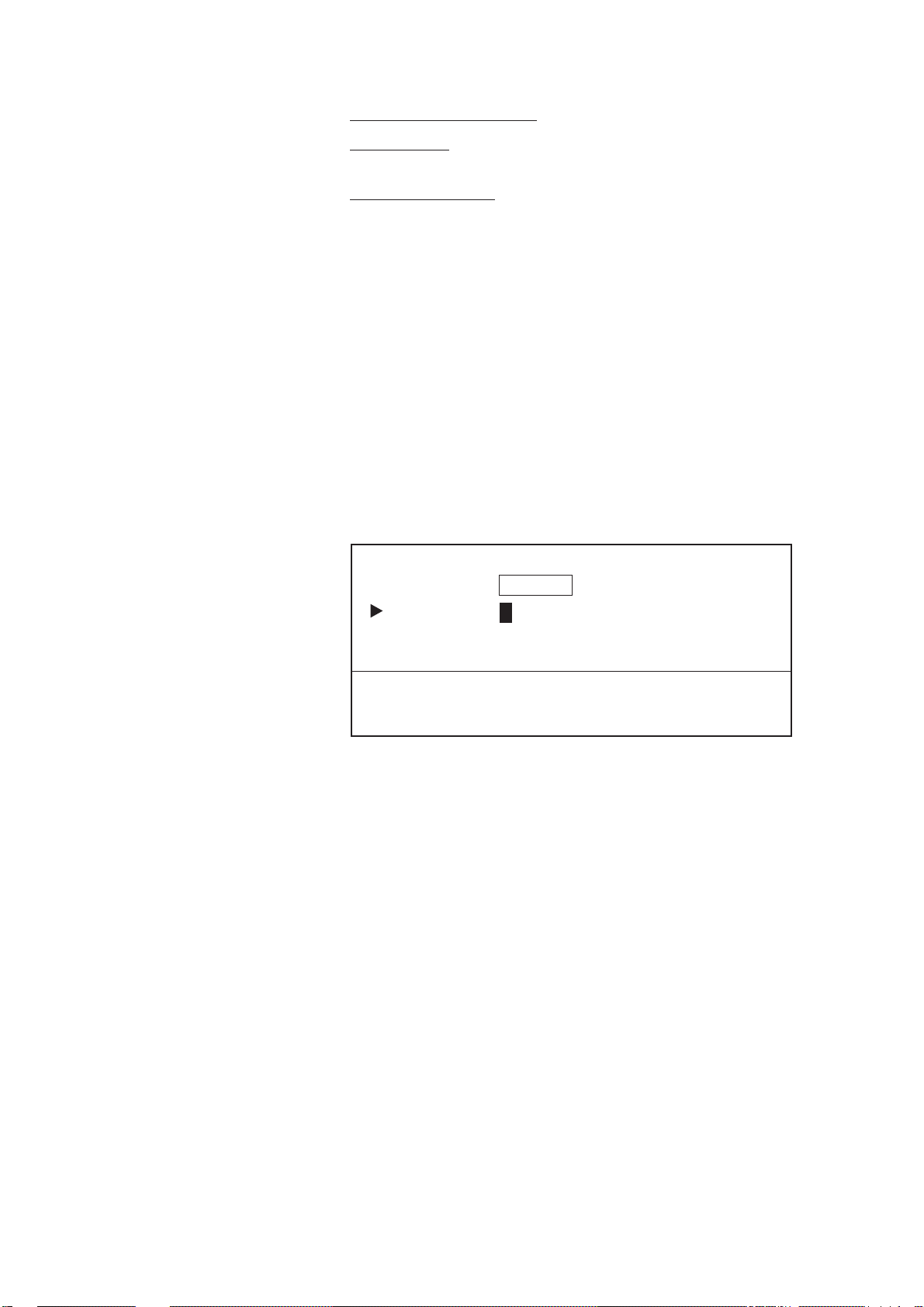
Summary of menu operation
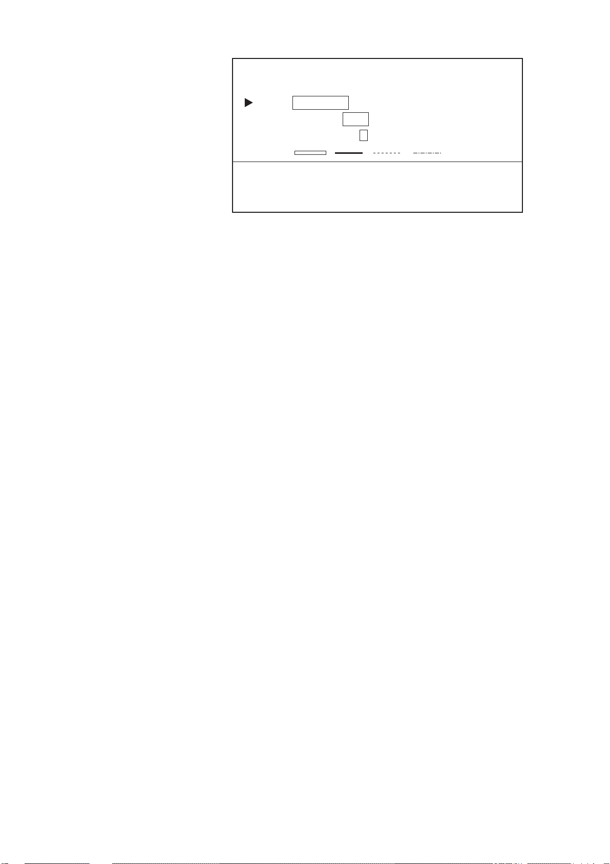
Figure 1-19 shows how to select items and options on the DESTINATION SETTING menu, which appears by pressing the [FR/TO] key.
DATA INPUT CURSOR
This cursor selects
location to enter data.
OPTION SELECTION CURSOR
This cursor, which moves by
and , shows current selection.
DESTINATION SETTING
DEST = SET CANCEL
MODE = CURSOR WAYPOINT ROUTE R/B
WPT NO. = 0 0 + _ _ + _ _ + _ _ + _ _ + _ _ + _ _
+ _ _ + _ _ + _ _ + _ _ + _ _ + _ _ + _ _
1-16
ITEM SELECTION CURSOR
This cursor, which moves
by and , selects
line to select or enter data.
Figure 1-19 DESTINATION SETTING menu
ENTER WAYPOINT NO.
This box provides abbreviated
instructions.

1.16 Operational Status Icons
Various icons at the bottom right-hand corner of the display to alert
the operator to operational status. T able 1-6 explains the meanings of
these icons.
Table 1-6 Operational status icons
.elbaileratadtrahCatadtrahc;degralnerevotrahC
H
.elbailernuebyam
kcart(ffodenrutgnidrocerkcarT
.)dloh
sraeppasidnocI.noitaloivmralA
rodegagnesidsimralanehw
.devomersimralafoesuac
.trahc
.ecneinevnoc
gnorwrodegralnerevotrahC
dracyromemfoegatlovwoL
;draoBCDGnoyrettabroyrettab
tseilraetayrettabecalper
L
L
nodeilppatesffonoitisoptrahC
.unemNOITISOPTCERROC
.)ylno0033-PG(
nodeilppatesffonoitisopL/L
unemSGNITTESLAITINISPG
1.17 Economy Mode
The economy mode turns off the LCD to lessen power consumption
(GD-3300: 13 W → 6W, GP-3300: 15 W → 8W). The track is continually recorded and plotted. To turn the economy mode on press
and hold down the [BRILL ECONO] key about three seconds. The
lamp on the key lights when the economy mode is on. T o turn off the
economy mode, press the key again.
1-17

1.18 Plot Mode Displays
Information displayed on the plot display depends on whether the
cursor is on or off. Figures 1-20 and 1-21 show sample plot displays
with the cursor on and off, respectively.
Plot display when cursor is on
Cursor bearing
Mark cursor
Cursor latitude
Cursor longitude
+36° 44.257’ N 140.50° 35.92NM
0.10NM
134° 40.719’ E 50.5°
Heading
PLOT
Heading
+36° 44.257’ N 50.5°
134° 40.719’ E 10.0KTS
40 42
MARK
MARK
48
WAYPOINT
07
MARK
OWN SHIP
MARK
6
2D 1.1
140.50
2D 1.1
COURSE
VECTOR
DESINATION
WAYPOINT
(SELECTED BY
CURSOR)
IDEAL COURSE TO
DESTINATION
MARK
Ship’s speed
1.46NM
°
0.10NM
Horizontal range
Plotting interval
Navigator/HDOP
Cursor range
Cursor bearing
Plotting interval
Navigator/HDOP
Target data
from radar
1-18
44
CURSOR
PLUS MARK
+
TRACK
MARK
WAYPOINT
08
1
LINE
H
Figure 1-20 Plot display, cursor on
L
L
Icon

Plot display when cursor is off
Bearing to destination
Mark cursor
Ship’s latitude
Ship’s longitude
36° 44.257’ N 59.8° 35.92NM
0.10NM
134° 40.719’ E 50.5°
Heading
PLOT
Heading
36° 44.257’ N 50.5°
134° 40.719’ E 10.0KTS
40 42
MARK
MARK
48
WAYPOINT
07
MARK
OWN SHIP
MARK
6
GPS 1.2
59.8
2D 1.2
COURSE
VECTOR
DESINATION
WAYPOINT
(SELECTED BY
CURSOR)
IDEAL COURSE TO
DESTINATION
MARK
Ship’s speed
1.46NM
°
0.10NM
Horizontal range
Plotting interval
Navigator/HDOP
Range to destination*
Bearing to destination*
Plotting interval
Navigator/HDOP
*: No waypoint data
when destination
waypoint is not
selected.
CURSOR
44
PLUS MARK
+
TRACK
MARK
1
WAYPOINT
08
LINE
Figure 1-21 Plot display, cursor off
L
H
L
1-19

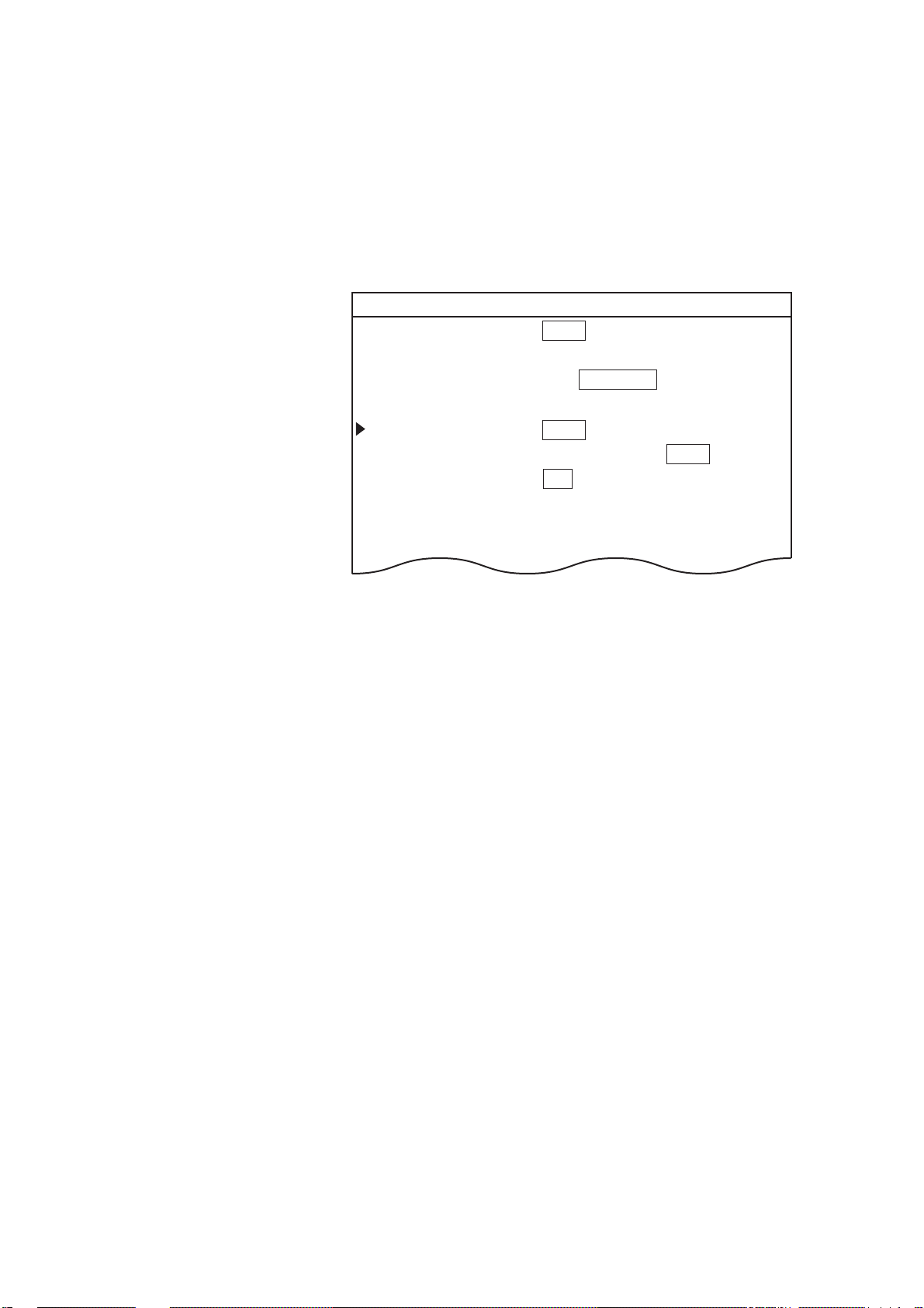
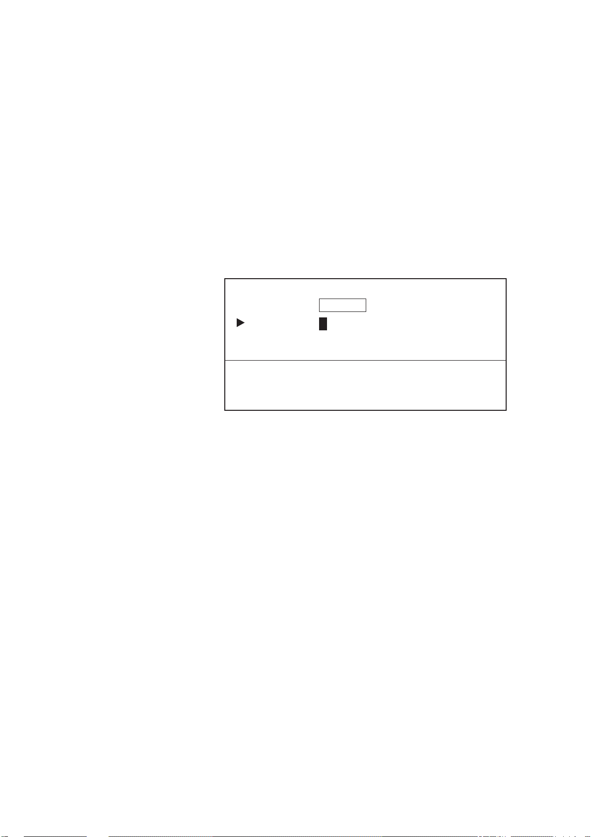
1.19 Setting the Time and Date
The internal clock marks time and is used to perform navigation calculations (for example, time-to-go). Set the clock and the date as follows:
1. Press the [MENU] key.
2. Press the [8] key to display the INITIAL SETTINGS menu.
8 INITIAL SETTINGS
VTD AVG TIME = 10MIN
DATE = 1998-04-00 (YYYY-MM-DD)
TIME = 10: 01: 50
EXTERNAL CLOCK = ON OFF
AUTOPILOT DISPLAY = ON OFF
TD INDICATION = LA LC OFF
Figure 1-22 INITIAL SETTINGS menu
3. Select DATE.
4. Enter date; year, month and day in that order. Enter year in four
digits and month and day in two each. To enter April 10, 1998,
for example, press [1], [9], [9], [8], [0], [4], [1], [0].
5. Select TIME.
6. Enter hour, minute and seconds in two digits each. T o enter 18:30,
for example, press [1], [8], [3], [0], [0], [0].
7. Press the [ENT] key.
Note: The time on the navigation data display is updated continually
by the internal clock but the time display on the INITIAL SETTINGS
menu is not updated.
1-20

2.1 Stopping Track Recording
When your ship is at anchor or returning to port you probably will
not need to record the track. You can stop recording the track, to
conserve the track memory, by activating the “hold” function. The
track is displayed but not recorded, thereby conserving the track
memory.
Press the [PLOT INTVL] key to display HOLD. The indications
“HOLD” and “H” appear on the display. The track is traced on the
display but is not stored. To resume plotting press the key again.
“HOLD” and “H” disappear.
TRACK
+36° 44.257’ N 340.5°
134° 40.719’ E 10.0KTS
1.46NM
109.8
2D 1.2
H
°
HOLD
HOLD indication
"H" icon
Figure 2-1 Location of “HOLD” indication
When the display is redrawn (by operating the [ZOOM IN], [ZOOM
OUT] keys, for example) the track is not traced while a control is
operated. When a control is released a line connects between position
when control was operated and position when control was released.
(a) T r ack displayed
during hold.
(b) T r ack erased
when display
is redrawn.
(c) Track is redrawn.
(d) Actual track
display at
release of hold.
(e) Actual track is erased when
display is redrawn during
hold or recording has been
restarted.
Figure 2-2 Track state and hold on/off
2-1

2.2 Track Color
The default track color is red, but you may change track color to any
one of seven colors. It is useful to change track color when returning
to port, changing course, etc.
1. Press the [TRACK COLOR] key to display the CHANGE
TRACK COLOR menu.
CHANGE TRACK COLOR
TRK COLOR = 1 2 3 4 5 6 7
SELECT TRACK COLOR BY NUMBER.
— : DELETE TRACK
Figure 2-3 CHANGE TRACK COLOR menu
2. Press appropriate numeric key among 1 to 7 to select color: [1],
Red; [2], Yellow; [3], Green; [4], Light-blue; [5] Purple; [6], Blue,
[7] White.
2.3 Changing Color, Appearance of Specific Track
You may wish to change the color and appearance of specific track.
This is useful for showing course change location, etc.
For example, change the color of track section AB to yellow and line
type to dashed line.
B
A
Figure 2-4 Track
1. Press [MENU], [9] and [1] to display the EDIT/TRACK MARK
menu.
2-2
9-1 EDIT TRACK/MARK
ITEM = CHG TRACK DEL TRACK CHG MARK DEL MARK
MODE = CURSOR BOX ON SCRN OFF SCRN
COLOR = 1 2 3 4 5 6 7 8 (SAME)
TYPE
SELECT COLOR AND/OR TYPE. SELECT STAR T AND ST OP POINTS
BY USING CURSOR, PRESSING ENT AFTER SETTINGEACH POINT.
PRESS ENT AGAIN TO CHANGE TRACK.
=
Figure 2-5 EDIT/TRACK MARK menu
2. Select CHG TRACK from the ITEM field.
3. Select method of change from the MODE field.
CURSOR: Select the track to edit with the crosshair cursor.
BOX: Circumscribe the track to edit with the box cursor.
ON SCRN: Edit all track displayed on the screen.
OFF SCRN: Edit track stored in memory.
4. Select the COLOR field.
5. Select new color. Using the above example, press the [2] key.
6. Select the TYPE field.
7. Select track type desired. Using the example, select the dashed
line.
8. For CURSOR or BOX select start point.
9. Press the [ENT] key.
10. For CURSOR or BOX select stop point.
11. Press the [ENT] key.
12. Press the [ENT] key again.
2-3

2.4 Deleting Track
Deleting track by color
One method of deleting unwanted track is by specifying track color .
Deleted track cannot be restored – exercise caution when deleting
track.
1. Press the [TRACK COLOR] key to display the CHANGE
TRACK COLOR menu.
CHANGE TRACK COLOR
TRK COLOR = 1 2 3 4 5 6 7
SELECT TRACK COLOR BY NUMBER.
— : DELETE TRACK
Figure 2-6 CHANGE TRACK COLOR menu
2. Press [-], and then press a numeric key among 1 - 7 to select color
to delete. If you want to delete all yellow color track, for example, press [-] and [2].
Deleting specific track with cursor, box cursor
You may delete unnecessary portions of ship’s track with the cursor
or box cursor. For example, if you wanted to delete the track from
point A to point B in the figure below, you would do the following:
POINT A
POINT B
Figure 2-7 Track
1. Press [MENU], [9], [1] to display the EDIT/TRACK menu.
9-1 EDIT TRACK/MARK
ITEM = CHG TRACK DEL TRACK CHG MARK DEL MARK
MODE = CURSOR BOX ON SCRN OFF SCRN
POINT A
b
a
cd
e
POINT B
2-4
SET BOX SIZE USING CURSOR, PRESSING ENT AT
TWO CORNERS.
PRESS ENT AGAIN TO DELETE TRACK.
Figure 2-8 EDIT/TRACK menu

2. Select DEL TRACK from the ITEM field.
3. Select BOX from the MODE field.
4. Set the top left-hand corner of the box cursor on point A by oper-
ating the trackball.
5. Press the [ENT] key.
6. Set the top right-hand corner of the box cursor on point B by
operating the trackball.
7. Press the [ENT] key.
8. Press the [ENT] key again.
Note that current track and replayed track cannot be deleted with the
crosshair cursor - use the box cursor.
Deleting all track
To delete all track, do the following:
1. Press the [MENU] key.
2. Press the [7] key to select APPORTION/DELETE MEMORY.
3. Press the [2] key to select DELETE TRACK.
7-2 DELETE TRACK
TRACK POINTS USED : 2167
MAX : 4000
ARE YOU SURE ? IF YES PRESS ENT.
Figure 2-9 DELETE TRACK display
4. Press the [ENT] key.
2-5

2.5 Track Plotting Interval
The plot interval determines how the track will be reconstructed on
the display and track storage time. The equipment has two plot intervals, plot interval 1 and plot interval 2, which you can set as desired.
You can select which one to use by the [PLOT INTVL] key. This
section shows you how to preset the plot intervals, on the INITIAL
SETTINGS menu.
How the track is drawn
The “quality” of the track displayed largely depends on the plot interval setting, smoothing rate, etc. In drawing the track, first the ship’s
position fed from the navigation receiver is stored into this unit’s
memory at an interval of time or distance selected by the operator.
This interval of time or distance is called the “Plot Interval” and it is
selected considering the ship’s speed, the chart scale, etc. If a shorter
interval is selected, a reconstructed course line is provided with better accuracy, but total storage time of the track is reduced.
Plot interval and track reconstruction
Obviously there is a trade off between smooth reconstruction of the
track and plot storage time: The shorter the interval the smoother the
reconstruction but storage time is reduced. Figure 2-10 compares plot
interval and track reconstruction.
ACTUAL
TRACK
Figure 2-10 Plot interval and track reconstruction
DISPLAYED
TRACK
Plot interval by time or distance
The plot interval can be selected by “Time” (00 sec. to 99.59 min.) or
“Distance” (00 nm to 9.99 nm). If the plot interval is selected by
distance, you will not use up memory points when the boat is anchored.
2-6
Setting plot interval 1 by time
The default plot method for plot interval 1 is time. T o set plot interval
1 by time do the following:
1. Press the [MENU] key.
2. Press the [8] key to select INITIAL SETTINGS.
3. Select the PLOT INTERVAL 1 field.
8 INITIAL SETTINGS
INTERNAL NAV = ON OFF
EXTERNAL NAV = GPS LC LA DC DR OFF
I/O DATA FORMAT = CIF NMEA183 NMEA180/182
SMOOTHING = 00 (0-15)
PLOT INTERVAL 1 = TIME (00M10S) DIST (0.10NM)
PLOT INTERVAL 2 = TIME (00M10S) DIST (0.10NM)
WAYPOINT MARK = ON OFF
Figure 2-11 INITIAL SETTINGS menu
4. Enter a plot interval. T o enter 30 seconds, for example, press [0],
[0], [3] and [0].
5. Press the [ENT] key.
Setting plot interval 2 to “time”
The default plot method for PLOT INTERVAL 2 is distance. However, it may be set for time as follows:
1. Press the [MENU] key.
2. Press the [8] key to select INITIAL SETTINGS.
3. Select the PLOT INTERVAL 2 field.
4. Select TIME.
5. Enter a plot interval. T o enter 15 minutes, for example, press [1],
[5], [0], [0].
6. Press the [ENT] key.
2-7

2.6 Customizing the Hold Function
The hold function stops recording the track to conserve track memory .
You can customize this functions as below.
Turning off track display when track is not being
recorded
When you stop recording the track in the default setting, the track is
displayed but not recorded. If you do not want to show the portion of
the track not recorded, you can turn it off as follows:
1. Press the [MENU] key.
2. Press the [8] key to select INITIAL SETTINGS.
3. Select OFF from the TRACK (HOLD PLOT) field.
4. Press the [ENT] key.
Line (hold plot) off
Figure 2-12 Appearance of track when track during
hold is not displayed
Connecting track after restarting track recording
The default hold function does not connect where recording is stopped
and restarted. If you want to connect those points do the following:
1. Press the [MENU] key.
2. Press the [8] key to select INITIAL SETTINGS.
3. Select ON from LINE (HOLD PLOT) field.
4. Press the [ENT] key.
2-8
Line (hold plot) on
Figure 2-13 Line connects track (not recorded)
after recording is resumed

2.7 Customizing the PLOT INTVL Key
Each time you press the [PLOT INTVL] key , in the default setting, a
plot interval is selected (plot interval 1 or plot interval 2) or recording
of the track is turned off. If you do not need one of the plot intervals
or you would like to reserve one of them for manual entry of plot
interval, do the following:
Setup for manually entering plot interval
To enable manual entry of plot interval by the [PLOT INTVL] key;
1. Press the [MENU] key.
2. Press the [8] key to select INITIAL SETTINGS.
3. Select PLOT INTERVAL 1 or PLOT INTERVAL 2, whichever
you want to use to manually enter plot interval.
4. Select TIME or DISTance.
5. Press the [CLR] key followed by the [ENT] key. Then, to manu-
ally enter plot interval, press the [PLOT INTVL] to select PLOT
INTERVAL chosen in step 3, enter plot interval, then press the
[ENT] key.
PLOT INTERVAL SETTING BY DISTANCE
PLOT INTERVAL = − − MIN − − SEC
Figure 2-14 PLOT INTERVAL menu
Tuning off a plot interval
To turn off a plot interval;
1. Press the [MENU] key.
2. Press the [8] key to select INITIAL SETTINGS.
3. Select PLOT INTERVAL 1 or PLOT INTERVAL 2, whichever
you want to turn off.
2-9

4. Select TIME or DISTance.
5. Press the [0] key four times followed by the [ENT] key. Then,
when you press the [PLOT INTVL] the plot interval selected above
is skipped.
2-10

3.1 Entering Marks
MARKS, LINES
Marks can be electrically inscribed on the display to denote important locations. 4,000 marks may be entered, and you have the choice
of mark shapes among circle, diamond, square, numeral (1-9), plus
mark and minus mark.
When the mark memory becomes full no marks can be entered. In
this case erase marks to enter new marks.
Entering marks with the cursor
1. With the trackball, place the cursor where you want to enter a mark.
2. Press mark key desired. To inscribe a plus mark, for example,
press the [+] key.
Entering marks at own ship’s position
1. Press the [CURSOR ON/OFF] key to turn off the cursor.
2. Press appropriate mark key (1-9).
Entering marks by manual input of latitude and
longitude
Marks may be entered by manual input of latitude and longitude coordinates. This method is convenient for exact placement of marks.
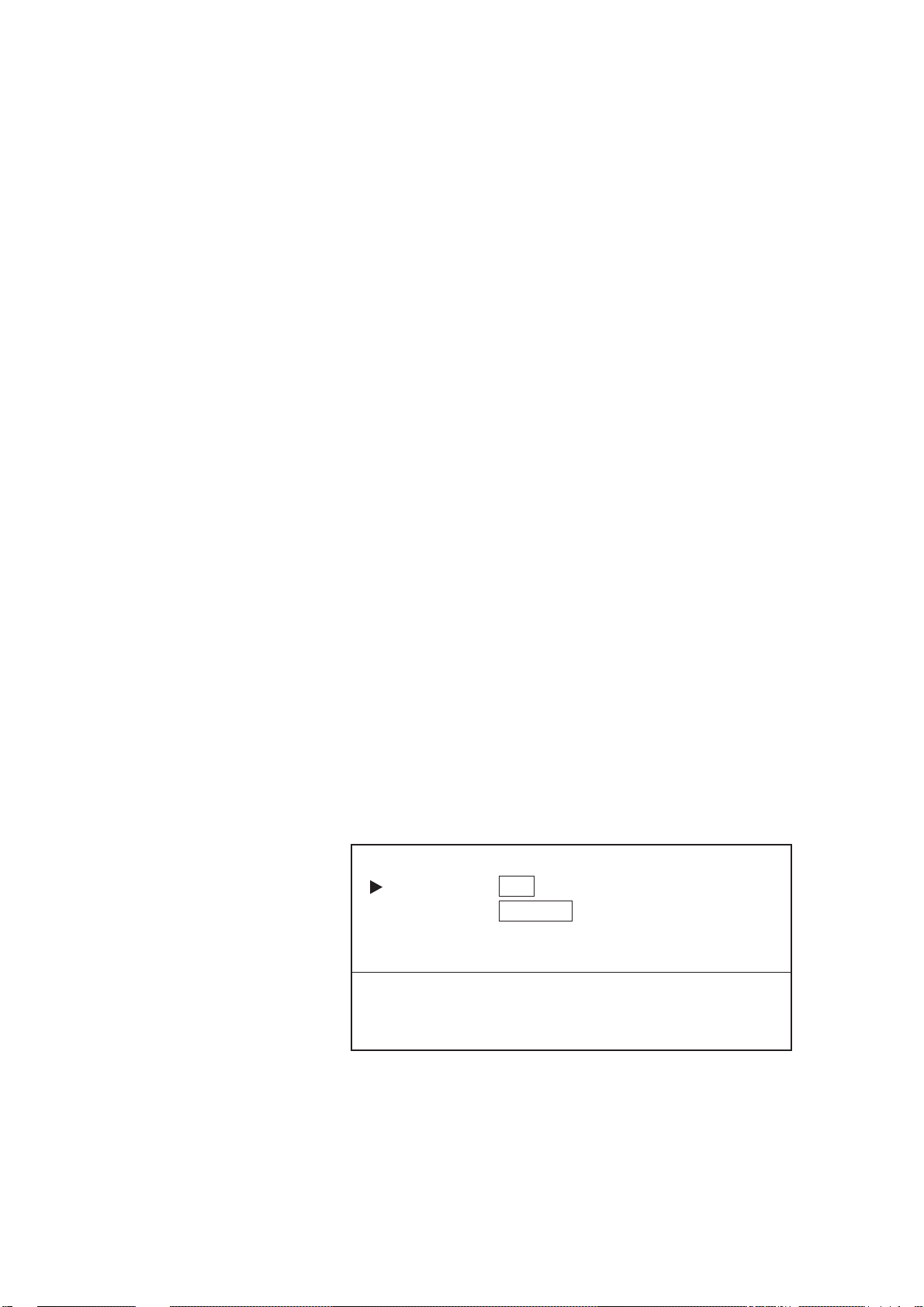
1. Press the [WPT] key to display the REGISTER WAYPOINT
menu.
REGISTER WAYPOINT
MODE = CURSOR L/L OS POS. R/B LIST
WPT NO. = − −
LATITUDE = − − ° − − . − − − N
LONGITUDE = − − − ° − − . − − − E
ENTER WAYPOINT NO., LATITUDE AND LONGITUDE.
PRESS ENT TO REGISTER WAYPOINT.
+ : N, E, DISPLAY − : S, W, NOT DISPLAY
Figure 3-1 REGISTER WAYPOINT menu
2. Select L/L from the MODE field.
3-1

3. Select the LATITUDE field. Enter latitude.
+36° 44.257’ N 340.5°
134° 40.719’ E 10.0KTS
1.46NM
109.8
°
0.10NM
2D 1.2
The color of "+"
is mark color.
4. Select the LONGITUDE field. Enter longitude.
5. Press appropriate mark key (1-9).
3.2 Changing Current Mark Color
Mark color is available in the colors shown on keys 1-7. When a
mark is entered it is inscribed in the color of the cursor mark in the
data window at the top of the display. You can change mark color
freely through the CHANGE MARK COLOR menu.
Figure 3-2 Location of mark color indication
1. Press the [MARK COLOR] key to show the CHANGE MARK
COLOR menu.
CHANGE MARK COLOR
MARK COLOR = 1 2 3 4 5 6 7
SELECT MARK COLOR BY NUMBER.
Figure 3-3 CHANGE MARK COLOR menu
2. Press appropriate numeric key among 1-7 to select color.
3. Press the [ENT] key.
3-2

3.3 Changing Shape, Color of Specific Marks
The color and shape of specific marks can be changed as follows:
1. Press [MENU], [9] and [1] to display the EDIT/TRACK MARK
menu.
9-1 EDIT TRACK/MARK
ITEM = CHG TRACK DEL TRACK CHG MARK DEL MARK
MODE = CURSOR BOX ON SCRN OFF SCRN
COLOR = 1 2 3 4 5 6 7 8 (SAME)
SHAPE= SAME
SELECT COLOR AND/OR SHAPE, AND PRESS ENT.
Figure 3-4 EDIT/TRACK MARK menu
2. Select CHG MARK from the ITEM field.
3. Select method of change from the MODE field:
CURSOR: Select the marks to edit with the crosshair cursor.
BOX: Circumscribe the marks to edit with the box cursor.
ON SCRN: Edit all marks displayed on the screen.
OFF SCRN: Edit marks stored in memory.
4. Select the COLOR field.
5. Select new mark color.
6. Select the TYPE field.
7. Select mark type desired.
8. For CURSOR or BOX, select start point.
9. Press the [ENT] key.
10. For CURSOR or BOX, select stop point.
11. Press the [ENT] key.
12. Press the [ENT] key again.
3-3

3.4 Deleting Marks
Deleting marks with the cursor
1. Operate the trackball to place the cursor on the mark you want to
delete.
2. Press the [CLR] key.
If the mark cannot be erased, there may be several marks superimposed on one another. In this case, press the [CLR] key several times.
Marks played back from a memory card cannot be deleted from screen.
Deleting specific marks
1. Press [MENU], [9] and [1] to display the EDIT/TRACK MARK menu.
2. Select DEL MARK from the ITEM field.
3. Select method of change from the MODE field:
CURSOR: Select the marks to erase with the crosshair cursor.
BOX: Circumscribe the marks to erase with the box cursor.
ON SCRN: Erase all marks displayed on the screen.
OFF SCRN: Erase marks stored in memory.
4. For CURSOR or BOX, select start point.
5. Press the [ENT] key.
6. For CURSOR or BOX, select stop point.
7. Press the [ENT] key.
8. Press the [ENT] key again.
Deleting all marks
1. Press [MENU], [7] and [3] to display the DELETE MARK screen.
7-3 DELETE MARK
TRACK MARKS USED : 3210
MAX : 4000
3-4
ARE YOU SURE ? IF YES PRESS ENT.
Figure 3-5 DELETE MARK screen
2. Press the [ENT] key.

3.5 External Event Mark
The external event mark shows your ship’s position on the display at
the exact moment the [EVENT] key is pressed on an external navigation device connected to the GD/GP-3300. It is marked on the screen
with a red triangle.
Erasing an external event mark
Place the cursor on the mark and press the [CLR] key.
Turning on/off event mark display
Y ou may turn the event mark on/of f. Press [MENU] and [8], and then
select ON or OFF from the EVENT MARK field as appropriate.
3.6 Target Mark
3.7 Lines
A target mark ( ) shows a radar target’s position. This mark is inscribed on the GD/GP-3300 when a certain key is pressed on the
radar. The following are a few of the FURUNO radars which can
output a target mark to the GD/GP-3300: FR-1500 MARK-2 series,
FR-1505 MARK-3 series, FR-2805 series, FR-2100 series, FR-2105
series.
A line can be electrically marked on the display to depict a fishing limit
line, coastline, small island, danger area, etc. A line is made up of a
series of latitude and longitude points: starting, intermediate and end.
Figure 3-6 Sample line
3-5
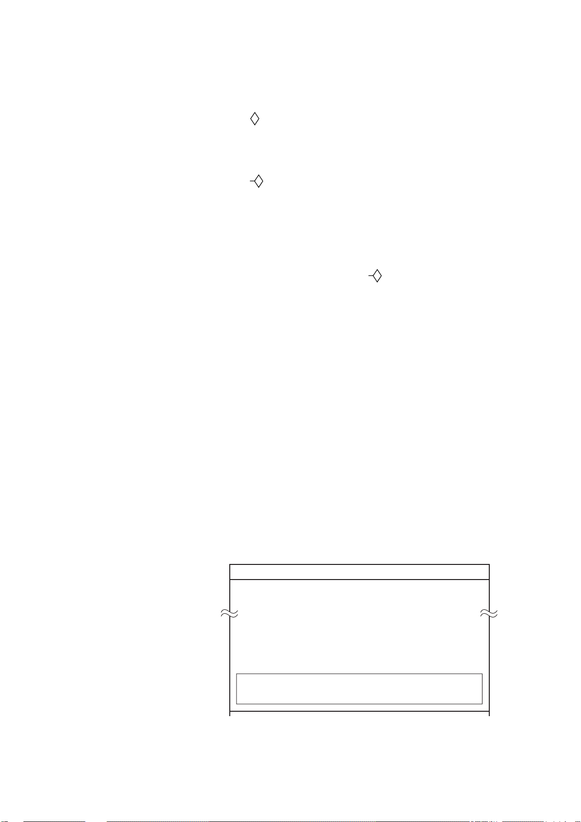
Entering a line
1. Operate the trackball to place the cursor on position desired for
starting point of line.
2. Press [
3. Operate the trackball to place the cursor on the position desired
for intermediate (or end) point.
4. Press [
5. To enter another point for the line, repeat steps 3 and 4.
Starting a new line
T o add a point to the last-entered line, you simply designate the location with the cursor and then press [
step 1 above.
]
]
]. To enter a new line, start at
Changing line color
Lines and marks share the same color. If you want to change line
color, therefore, press the [MARK COLOR] key and then select color
desired.
Deleting lines
Deleting individual points on a line
Operate the trackball to set cursor intersection on a triangle mark of
the line you want to delete and then press the [CLR] key.
Deleting all lines
1. Press [MENU], [7] and [3] to display the DELETE MARK screen.
7-3 DELETE MARK
TRACK MARKS USED : 3210
MAX : 4000
ARE YOU SURE ? IF YES PRESS ENT.
3-6
Figure 3-7 DELETE MARK menu
2. Press the [ENT] key.
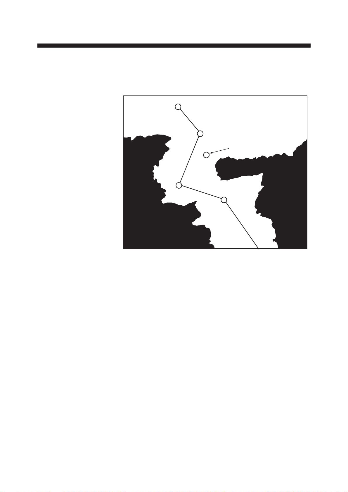
WAYPOINTS
In navigation terminology, a particular location is known as a
“Waypoint,” whether it be a starting point, a destination point or an
intermediate point on a voyage.
WAYPOINT 4
WAYPOINT 3
DANGER POINT
WAYPOINT 2
WAYPOINT 1
Figure 4-1 Waypoints
The GD/GP-3300 series has 98 waypoints into which you can enter
position information. They are numbered from “zero-zero” (00) to
ninety-nine (99) and colored yellow. (Waypoint color cannot be
changed.) Waypoint “00” is reserved for use when your present position is used as a starting waypoint, to find range and bearing to a
point. This will be explored in more detail later.
W aypoint “99” is an external waypoint where “T o” waypoint selected
on the connected navaid is automatically stored.
4-1

4.1 Entering W aypoints
A waypoint may be entered by latitude and longitude coordinates, by
the cursor, at ship’ s position, by range and bearing, and with position
from a navigator.
Waypoint entry by L/L coordinates
Let us assume for purposes of illustration that you wish to enter the
position of San Francisco into waypoint 6. The coordinates are: 37
degrees, 40.000 minutes North Latitude, and 122 degrees, 24.000
minutes West Longitude. The keying sequence would be as follows:
1. Press the [MENU] key.
2. Press the [1] key to display the WAYPOINT list.
Data input
cursor
1 WAYPOINT
NO. DISP
134° 44.555’N 135° 23.456’E A B C 1 2 YES
234° 43.444’N 135° 22.445’E YES
3
− −°
− −.− − −’N− − −° − −.− − −
434° 41.222’N 135° 55.221’E YES
534° 32.125’N 135° 27.658 E YES
6
− −°
− −.− − −’N− − −° − −.− − −
733° 45.658’N 134° 46.265’E NO
833° 56.012’N 134° 15.456’E NO
9
− −°
− −.− − −’N− − −° − −.− − −
10
− −°
− −.− − −’N− − −° − −.− − −
11
− −°
− −.− − −’N− − −° − −.− − −
12
− −°
− −.− − −’N− − −° − −.− − −
13
− −°
− −.− − −’N− − −° − −.− − −
14
− −°
− −.− − −’N− − −° − −.− − −
15
− −°
− −.− − −’N− − −° − −.− − −
20
− −°
− −.− − −’N− − −° − −.− − −
99
− −°
− −.− − −’N− − −° − −.− − −
’E
’E
’E
’E
’E
’E
’E
’E
’E
’E
’E
Comment
4-2
ENTER L/L POSITION BY USING CURSOR.
+ : N, E, YES — : S, W, NO
’CHANGE’ KEY : SCROLL PAGE
Figure 4-2 Waypoint list
3. Place the data input cursor on waypoint 6.
4. Enter latitude.
Cancel entire line of data: Press the [CLR] key.
Change data: Place data input cursor on wrong data, and then
reenter data.
Switch coordinates: [+] key , changes coordinate to North or East,
[-] key, changes coordinate to South or West.
5. Place the data input cursor to the first digit of longitude and then
enter longitude.
6. Enter comment, if desired.
Note: Waypoint comment can be entered on the Waypoint List.
See 4.2 Entering a Waypoint Comment.
7. Press the [ENT] key.
Waypoint entry by cursor
1. Press the [WPT] key to display the REGISTER WAYPOINT
menu.
REGISTER WAYPOINT
MODE = CURSOR L/L OS POS. R/B LIST
WPT NO. = − −
ENTER W AYPOINT NO., AND DESIGNATE WAYPOINT POSITION BY
USING CURSOR. + : DISPLAY
− : NOT DISPLAY
Figure 4-3 REGISTER WAYPOINT menu
2. Select CURSOR from the MODE field, if it is not already se-
lected.
3. Select WPT NO.
4. Enter waypoint number in two digits. If the waypoint number is
07, for example, press [0] and [7].
Note 1: If the waypoint number is already used, “(USED)” appears
to alert you. You can enter a new number by pressing the [CLR]
key, or overwrite the waypoint number by going to step 5.
Note 2: You can register a waypoint without entering waypoint
number, in which case the unit automatically registers the waypoint
in the youngest, unused waypoint. For example, if waypoints 01,
02, 04 and 05 are used when you enter a waypoint without
designating waypoint number, the unit will automatically register
that waypoint as waypoint number 03.
4-3

5. Operate the trackball to place the cursor on position desired.
6. Press the [ENT] key.
7. Press the [WPT] key to finish.
Waypoint entry at own ship’s position
1. Press the [WPT] key to display the REGISTER WAYPOINT
menu.
REGISTER WAYPOINT
MODE = CURSOR L/L OS POS. R/B LIST
WPT NO.
ENTER WAYPOINT NO.
PRESS ENT T O REGISTER WAYPOINT. + : DISPLAY
= − −
− : NOT DISPLAY
Figure 4-4 REGISTER WAYPOINT menu
2. Select OS POS from the MODE field.
3. Select WPT NO.
4. Enter waypoint number in two digits.
5. Press the [ENT] key.
6. Press the [WPT] key to finish.
Waypoint entry by range and bearing
This method is useful when you want to enter a waypoint using range
and bearing to a target found on radar.
1. Press the [WPT] key to display the REGISTER WAYPOINT
menu.
2. Select R/B from the MODE field.
REGISTER WAYPOINT
MODE = CURSOR L/L OS POS. R/B LIST
WPT NO. = − −
RANGE = − − − . − − − NM
BEARING = − − − . − ° MAG
ENTER WAYPOINT NO., RANGE AND BEARING.
PRESS ENT TO DISPLAY WPT L/L.
PRESS ENT AGAIN TO REGISTER WAYPOINT.
+ : N, E, DISPLAY − : S, W, NOT DISPLAY
4-4
Figure 4-5 REGISTER WAYPOINT menu

3. Select WPT NO.
4. Enter waypoint number in two digits.
5. Select the RANGE field.
6. Enter range.
7. Select the BEARING field.
8. Enter bearing.
9. Press the [ENT] key to calculate position. The latitude and longi-
tude position of the range and bearing entered appears on the
display.
10. Press the [ENT] key again to register the waypoint.
W aypoint entry by navigation aid
The “TO” waypoint selected on the navigation aid connected is automatically sent to the GD/GP-3300 as an external waypoint.
4.2 Entering a Comment for a Waypoint
You can enter a comment for a waypoint in the WA YPOINT list. The
comment can consist of 10 alphanumeric characters.
1. Press the [MENU] key followed by the [1] key to display the
WAYPOINT LIST.
2. Press arrow keys to set data input cursor on the line desired in the
comments column.
3. Operate the trackball to circumscribe the first character for your
comment. You can switch between upper and lower case characters with the [ZOOM IN], [ZOOM OUT] keys. See Figure 4-6.
This cursor
selects character.
ZOOM
OUT
ZOOM
IN
(These are lower case characters.)
Figure 4-6 Characters available for use as a waypoint comment
4-5
4. Press the [ENT] key. (If you enter a wrong character, set the data
input cursor on wrong character and then enter correct character .)
5. Repeat steps 2 and 3 to complete comment.
6. Press [→] to set the cursor out of the comments column and then
press the [ENT] key.
4.3 Turning Specific Waypoint Displays On/Off
Turning on/off specific waypoints displays through
the REGISTER WAYPOINT menu
1. Press the [WPT] key to display the REGISTER WAYPOINT
menu.
REGISTER WAYPOINT
MODE = CURSOR L/L OS POS. R/B LIST
WPT NO. = − −
ENTER WAYPOINT NO., AND DESIGNATE WAYPOINT
POSITION BY USING CURSOR.
Figure 4-7 REGISTER WAYPOINT menu
2. Select L/L from the MODE field.
3. Select WPT NO.
4. Press [-] (turn off) or [+] (turn on), enter waypoint number to turn
on/off.
5. Press the [ENT] key.
4-6

Turning on/off specific waypoints displays
through the waypoint list
1. Press the [MENU] key to display the menu.
2. Press the [1] key to display the WAYPOINT list.
1 WAYPOINT
NO. DISP
134° 44.555 N 135° 23.456 E A B C 1 2 YES
234° 43.444 N 135° 22.445 E YES
− −°
3
434° 41.222 N 135° 55.221 E YES
534° 32.125 N 135° 27.658 E YES
6
7
8
9
10
11
12
13
− −.− − −’N− − −° − −.− − −
− −°
− −.− − −’N− − −° − −.− − −
− −°
− −.− − −’N− − −° − −.− − −
− −°
− −.− − −’N− − −° − −.− − −
− −°
− −.− − −’N− − −° − −.− − −
− −°
− −.− − −’N− − −° − −.− − −
− −°
− −.− − −’N− − −° − −.− − −
− −°
− −.− − −’N− − −° − −.− − −
− −°
− −.− − −’N− − −° − −.− − −
’E
’E
’E YES
’E YES
’E
’E
’E
’E
’E
DISP
3. Place the cursor on the waypoint (number) you want to turn on/off.
4. Set the cursor in the DISP column.
5. Press [-] to display NO, or [-] to display YES.
6. Press the [ENT] key.
4.4 Deleting W aypoints
You can delete unnecessary waypoints by the cursor or through the
waypoint list.
Deleting waypoints by cursor
1. Place the cursor on the waypoint you want to delete.
2. Press the [CLR] key.
Figure 4-8 Sample waypoint list
4-7
Deleting waypoints through waypoint list
1. Press the [MENU] key followed by the [1] key to display the
WAYPOINT list.
2. Select the waypoint you want to delete.
3. Press the [CLR] key.
4. To delete another waypoint, repeat steps 2 and 3.
5. Press the [ENT] key.
Deleting external waypoint (99)
1. Cancel destination waypoint on connected navigation aid.
2. Display the cursor and operate the trackball to place the cursor on
waypoint 99.
3. Press the [CLR] key.
4.5 Destination Waypoint
By setting a destination waypoint, you can find the range and bearing
from your vessel to a latitude and longitude position. You can set a
destination waypoint by cursor, waypoint number, range and bearing, and route number. (Route number is a special method so it is
dealt with in a later section.)
Setting destination waypoint by cursor
1. Press the [FR/TO] key to display the DESTINATION SETTING
menu.
DESTINATION SETTING
DEST = SET CANCEL
MODE = CURSOR WAYPOINT ROUTE R/B
SELECT DESTINATION BY USING CURSOR AND PRESS ENT .
INTERMEDIATE POINTS CAN BE SET BY USING + KEY.
4-8
Figure 4-9 DESTINATION SETTING menu
2. Select CURSOR from the MODE field.

3. Place the cursor on latitude and longitude position desired for
DESTINATION SETTING
DEST = SET CANCEL
MODE = CURSOR WAYPOINT ROUTE R/B
WPT NO. = 0 0 + − − + − − + − − + − − + − − + − − + − − +
+ − − + − − + − − + − − + − − + − − + − − + −
ENTER WAYPOINT NO.
destination waypoint. Note that if you place cursor near a mark
or a waypoint displayed, cursor position (destination waypoint)
is pulled into the mark displayed.
4. Press the [ENT] key
Setting destination waypoint by waypoint
number
1. Press the [FR/TO] key to display the DESTINATION SETTING
menu.
Figure 4-10 DESTINATION SETTING menu
2. Select WAYPOINT from the MODE field.
3. Select WPT NO.
4. Enter waypoint number(s) in two digits. If the waypoint number
is 07, for example, press [0] and [7].
5. Press the [ENT] key.
Note: The message “DATA ERROR” appears on the display when
the waypoint number entered is not registered.
Setting destination waypoint by range and
bearing
1. Press the [ENT] key to display the DESTINATION SETTING
menu.
2. Select R/B from the MODE field.
3. Select RANGE.
4. Enter range.
5. Select BEARING.
6. Enter bearing.
7. Press the [ENT] key twice.
4-9

When you set a destination waypoint...
• The DESTINATION SETTING menu disappears.
• Destination waypoint is marked with a yellow flag (except desti-
nation set by registered waypoints).
• Your ship’s position is shown as waypoint 00.
• A light-blue dashed line connects your ship’s position with desti-
nation waypoint. This line shows the ideal course.
Destination
Waypoint
"00" marks your ship’s
position when destination
waypoint is selected.
Figure 4-11 How a destination waypoint is shown on the display
Ideal course
to destination
4-10

Displaying range and bearing to destination
waypoint
Press the [PLOT] key to display the DATA DISPLAY (2).
Bearing to destination
DATA DISPLAY (1)
36° 34.000’ N 176.5° 14.5NM
0’ 10"
134° 20.524’ E 340.5°
Heading
2D 1.2
DATA DISPLAY (2)
PLOT
36° 34.000’ N 340.5°
134° 20.524’ E 10.0KTS
40 42
48
00
0.215NM
176.5
0’ 10"
2D 1.2
°
Range to destination
Waypoint
Bearing to destination
waypoint
44
Figure 4-12 Location of destination waypoint information
4-11

4.6 Cancelling Destination Waypoint
DESTINATION SETTING
DEST = SET CANCEL
MODE = CURSOR WAYPOINT ROUTE R/B
WPT NO. = 0 0 + − − + − − + − − + − − + − − + − − + − − +
+ − − + − − + − − + − − + − − + − − + − − + −
ENTER WAYPOINT NO.
Once you arrive at your destination you probably won’t need the destination waypoint. You can cancel it, three ways.
Cancelling destination waypoint through the
menu
1. Press the [FR/TO] key to display the DESTINATION SETTING
menu. The first line shows the latitude and longitude of the destination waypoint for your confirmation.
Figure 4-13 DESTINATION SETTING menu
2. Select CANCEL from the DEST field.
3. Press the [ENT] key.
Cancelling destination waypoint by key input
Method 1: Press [FR/TO], [CLR], [ENT].
Method 2: Press [FR/TO], [0], [ENT].
4-12

ROUTE NAVIGATION
In many cases a trip from one place to another involves several course
changes, requiring a series of route points (waypoints) which you
navigate to, one after another. The sequence of waypoints leading to
the ultimate destination is called a route. This unit can automatically
advance to the next waypoint on a route, so you do not have to change
the destination waypoint repeatedly. The figure below shows an example of a route between two points, involving six waypoints.
ROUTE: 01 ( PORT/ PORT)
PORT
PORT
WAYPOINT 01
FORWARD
WAYPOINT 06
WAYPOINT 02
REVERSE
Transit
Order
1
2
3
4
5
6
WAYPOINT 03
Waypoint
WPT 06
WPT 05
WPT 04
WPT 03
WPT 02
WPT 01
WAYPOINT 04
WAYPOINT 05
Figure 5-1 Sample route
You can store 10 routes and a route may contain up to 15 waypoints.
The 3300 automatically assigns a route number from 0-9. Be sure to
record all important routes in a separate log and save them to a memory
card. This unit is not a fail-safe record keeping device.
5-1
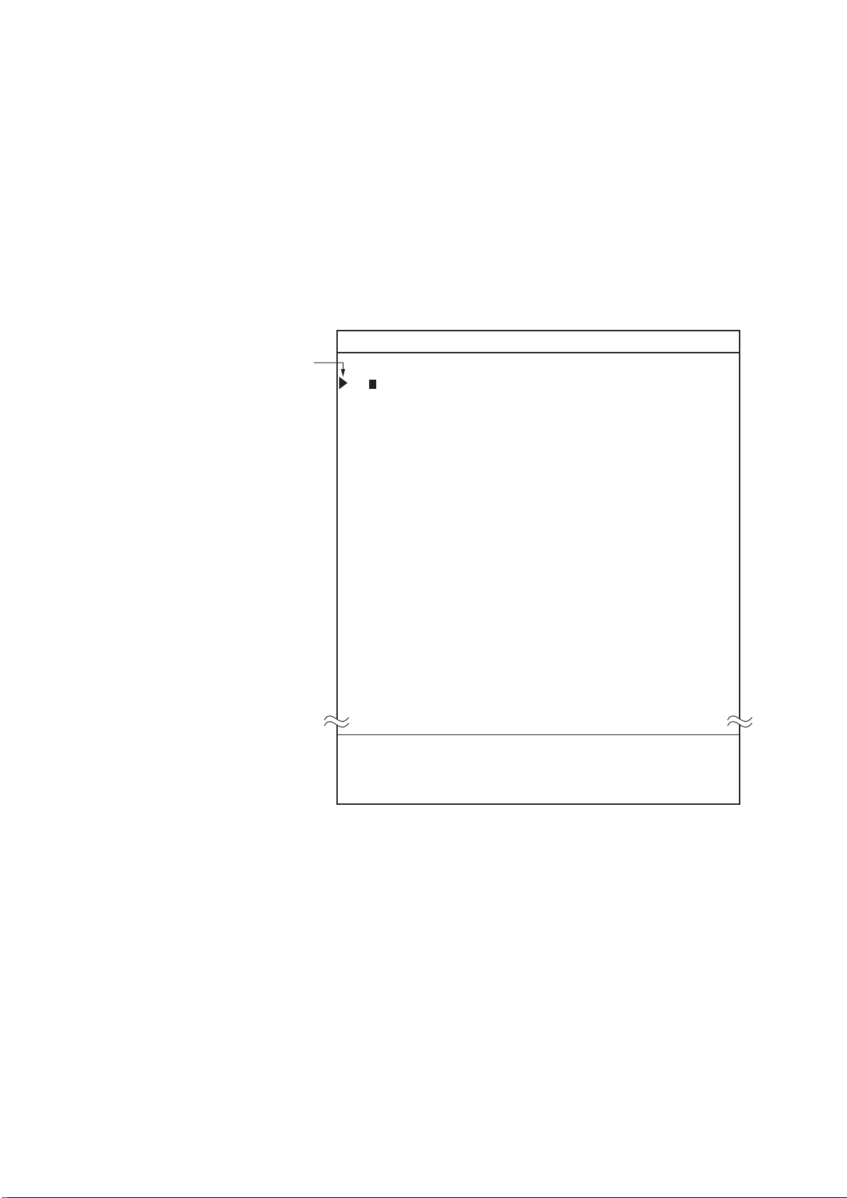
5.1 Creating Routes
You can create a route three ways: through the route list (by latitude
and longitude coordinates), by previously registered waypoints, by
cursor.
Creating routes through the route list
1. Press the [MENU] key.
2. Press the [2] key to display the ROUTE list.
TRANSIT
ORDER
2 ROUTE
WAYPOINT LATITUDE LONGITUDE DISTANCE TTG
1(− −) − − ° − −.− − −’N − − −° − −.− − −’ E − − − . − − NM − − − − − . − H
2(− −) − − ° − −.− − −’N − − −° − −.− − −’ E − − − . − − NM − − − − − . − H
3(− −) − − ° − −.− − −’N − − −° − −.− − −’ E − − − . − − NM − − − − − . − H
4(− −) − − ° − −.− − −’N − − −° − −.− − −’ E − − − . − − NM − − − − − . − H
5(− −) − − ° − −.− − −’N − − −° − −.− − −’ E − − − . − − NM − − − − − . − H
6(− −) − − ° − −.− − −’N − − −° − −.− − −’ E − − − . − − NM − − − − − . − H
7(− −) − − ° − −.− − −’N − − −° − −.− − −’ E − − − . − − NM − − − − − . − H
8(− −) − − ° − −.− − −’N − − −° − −.− − −’ E − − − . − − NM − − − − − . − H
9(− −) − − ° − −.− − −’N − − −° − −.− − −’ E − − − . − − NM − − − − − . − H
10 (− −) − − ° − −.− − −’N − − −° − −.− − −’ E − − − . − − NM − − − − − . − H
11 (− −) − − ° − −.− − −’N − − −° − −.− − −’ E − − − . − − NM − − − − − . − H
12 (− −) − − ° − −.− − −’N − − −° − −.− − −’ E − − − . − − NM − − − − − . − H
13 (− −) − − ° − −.− − −’N − − −° − −.− − −’ E − − − . − − NM − − − − − . − H
14 (− −) − − ° − −.− − −’N − − −° − −.− − −’ E − − − . − − NM − − − − − . − H
15 (− −) − − ° − −.− − −’N − − −° − −.− − −’ E − − − . − − NM − − − − − . − H
ROUTE NO
1
SHIP SPD FOR TTG CALC = 10.0 KTS
TO NEXT PAGE
ENTER L/L POSITION BY USING CURSOR.
+ : N, E, SELECT − : S, W, DESELECT
’CHANGE’ KEY : SCROLL PAGE
5-2
Figure 5-2 ROUTE list
3. Enter latitude and longitude of each route waypoint.
4. Press the [ENT] key.
Creating routes with waypoint numbers: MENU
ROUTE NO.
MODE = CURSOR WAYPOINT ??? LIST
ROUTE NO.= − −
WPT NO. =
0 0
+ − − + − − + − − + − − + − − + − − + −
+ − − + − − + − − + − − + − − + − − + − − + − −
ENTER ROUTE NO., AND WAYPOINT NO.
PRESS ENT TO REGISTER.
key
1. Press the [MENU] key.
2. Press the [2] key to display the ROUTE list.
2 ROUTE ROUTE NO 1
WAYPOINT LATITUDELONGITUDE DISTANCE TTG
1 (2 8) 3 4 ° 4 5.1 4 6’ N 1 3 5° 2 1.2 1 7 E− − − . − − NM − − − − − . − H
2(− −) − − ° − −.− − −’N − − −° − −.− − −’ E − − − . − − NM − − − − − . − H
3(− −) − − ° − −.− − −’N − − −° − −.− − −’ E − − − . − − NM − − − − − . − H
Figure 5-3 ROUTE list
3. Press [←] twice.
4. Enter first waypoint number of route in two digits. If it is 08, for
example, press [0] and [8]. The L/L position of the waypoint appears.
5. Press [↓] followed by [←] twice to send the data input cursor to
the next line. Enter waypoint number. Its L/L position appears.
6. Repeat step 6 to enter another waypoint.
7. To enter another route, press the [
] key to scroll page.
8. After entering all information, press the [ENT] key.
Creating routes with waypoint numbers: ROUTE
key
1. Press the [ROUTE] key to display the ROUTE NO. menu.
Figure 5-4 ROUTE NO. menu
2. Select WAYPOINT from the MODE field.
3. Select ROUTE NO.
4. Enter route number in two digits. If the route number is 01, for
example, press [0] and [1].
5-3

5. Select WPT NO.
ROUTE NO.
MODE = CURSOR WAYPOINT ??? LIST
ROUTE NO.= − −
ENTER ROUTE NO., AND SELECT WAYPOINTS,
PRESSING + KEY AFTER SELECTIONS.
PRESS ENT TO REGISTER.
6. Enter waypoint numbers.
7. Press the [ENT] key.
Creating routes with the cursor
1. Press the [ROUTE] to display the ROUTE NO. menu.
Figure 5-5 ROUTE NO. menu
2. Enter route number in two digits. (Don’t press the [ENT] key
yet.)
3. Operate the trackball to place the cursor on L/L position desired
for first route waypoint.
4. Press [+]. If you want to cancel a point, press [-].
5. Repeat steps 3 and 4 to enter other points.
6. Press the [ENT] key. Route waypoints entered by the cursor are
marked with a yellow flag and connected with a green dashed
line.
5-4

5.2 Following a Route
ROUTE NO.
DEST = SET CANCEL
MODE = CURSOR WAYPOINT ROUTE R/B
ROUTE NO.= − −
FWD/REV = FORWARD REVERSE
ENTER ROUTE NO., AND SELECT FORWARD OR
REVERSE.
Following a route is the process by which you use a stored route for
navigation. This unit displays navigation information to guide you
from one waypoint to the next, as it automatically switches from
waypoint to waypoint in sequence.
1. Press the [FR/TO] key to display the DESTINATION SETTING
menu.
Figure 5-6 DESTINATION SETTING menu
2. Select ROUTE from the MODE field.
3. Select the ROUTE NO. field.
4. Enter route number by two digits.
5. Select the FWD/REV field.
6. Select route transit direction; forward or reverse.
7. Press the [ENT] key.
About route navigation
When a route is selected for navigation its waypoints are marked by
yellow flags (except waypoint-created routes) and connected with a
light-blue dashed line.
The unit will automatically select the first waypoint in the route plan
for you go to towards from your present position. Once you arrive
within the radius of the arrival alarm, the unit will automatically switch
to the next waypoint in sequence.
You might also try another way to “arrive” at your destination
waypoint. This involves changing the arrival alarm range to a larger
number. This way too is fraught with danger, for if you specify the
alarm range too loosely , let’s say 0.5 nautical miles, you will need to
allow the automatic switching to the next destination waypoint to
occur, but you may then define a new course to the next waypoint
5-5

that takes you through a seawall or over land! It is far better to leave
a reasonable arrival alarm range of say 0.1 nautical miles, and when
you get as close as safely possible to the desired waypoint which is
now blocked then manually override the route planning mode and go
to manual waypoint sequencing.
Note: In some instances waypoints on a route may not be connected.
If this is the case;
1) Check setting of ROUTE LINE on menu 96.
2) Try reformatting the display.
3) An intermediate waypoint may be selected by the arrival alarm
range. If this is the case, make the alarm range smaller. Note that the
arrival alarm range remains in effect in route navigation even when
the arrival alarm itself is turned off.
5.3 Temporarily Deselecting a Route Waypoint
A route waypoint may be deselected temporarily by entering a “-”
(minus) to the left of the route waypoint on the ROUTE list. Using
Figure 5-7 as an example, you would want to temporarily deselect
route waypoints 04, 05 and 06, since your ship is to traverse the route
in the order of route waypoints 03, 02 and 01.
The temporarily deselected route waypoint may be restored at any
time by entering a plus sign next to the deselected route waypoint
number.
Waypoint 01
PORT
Waypoint 06
PORT
Waypoint 02
Waypoint 03
Waypoint 04
Waypoint 05
Figure 5-7 Example of when to deselect waypoints
1. Press the [MENU] key.
2. Press the [2] key to display the ROUTE list.
5-6
3. Press the [
] key to select route.
4. Place the cursor on the waypoint you want to deselect.
5. Press [←] to place the cursor on a digit in the WAYPOINT col-
umn.

2 ROUTE ROUTE NO 1
WAYPOINT LATITUDE LONGITUDE DISTANCE TTG
Cursor
Minus sign
(waypoint
deselected)
1 − (06) 34° 21.185’ N134° 08.122’E − − − . − − NM − − − − − . − H
2 − (05) 34° 24.068’ N135° 45.012’E − − − . − − NM − − − − − . − H
3 − (04) 35° 31.254’ N135° 20.314’E − − − . − − NM − − − − − . − H
4 − (03) 36° 18.314’ N134° 31.234’E − − − . − − NM − − − − − . − H
5 (02) 37° 33.568’ N134° 20.128’E − − − . − − NM − − − − − . − H
6 (01) 38° 01.438’ N133° 18.258’E − − − . − − NM − − − − − . − H
Figure 5-8 ROUTE list
6. Press [-]. In the figure above waypoints 1, 2, 3 and 4 are deselected.
5.4 Deleting Route Waypoints
Deleting specific route waypoints
1. Press the [MENU] key to display the menu.
2. Press the [2] key to select ROUTE.
3. Select route number by pressing the [
] key.
4. Place the cursor on route waypoint you want to delete.
5. Press the [CLR]. In Figure 5-9, for example, position data for
waypoint no. 2 is deleted. The next time you select the route, all
route waypoints are automatically renumbered.
2 ROUTE ROUTE NO 1
WAYPOINT LATITUDE LONGITUDE DISTANCE TTG
1(− −) 3 4 ° 4 5.1 4 6’ N 1 3 5° 2 1.2 1 7’ E− − − . − − NM − − − − − . − H
2(− −) − − ° − −.− − −’N − − −° − −.− − −’ E− − − . − − NM − − − − − . − H
3(− −) 3 3 ° 1 1.2 3 4’ N 1 2 8° 3 2.1 0 8’ E− − − . − − NM − − − − − . − H
4(− −) 2 8 ° 3 4.5 6 4’ N 1 3 0° 4 1.4 1 6’ E− − − . − − NM − − − − − . − H
Figure 5-9 ROUTE list, showing deleted waypoint
6. Press the [ENT] key.
5-7

Deleting all route waypoints
1. Press the [ROUTE] key.
2. Select WAYPOINT.
3. Select ROUTE NO.
4. Enter route number.
5. Select WPT NO.
6. Press the [CLR] key followed by the [ENT] key.
5.5 Cancelling Route Navigation
You can cancel route navigation as follows:
1. Press the [FR/TO] key to display the DESTINATION SETTING
menu.
2. Select CANCEL.
3. Press the [ENT] key. The color of the line connecting route
waypoints changes from light-blue to green to indicate that route
navigation has been cancelled.
5-8

5.6 Route Calculation
The route calculation function provides distance and time-to-go calculations between each route waypoint.
1. Press the [MENU] key.
2. Press the [2] key to select ROUTE.
2 ROUTE ROUTE NO 1
WAYPOINT LATITUDE LONGITUDE DISTANCE TTG
1(− −) − − ° − −.− − −’N − − −° − −.− − −’ E − − − . − − NM − − − − − . − H
2(− −) − − ° − −.− − −’N − − −° − −.− − −’ E − − − . − − NM − − − − − . − H
3(− −) − − ° − −.− − −’N − − −° − −.− − −’ E − − − . − − NM − − − − − . − H
4(− −) − − ° − −.− − −’N − − −° − −.− − −’ E − − − . − − NM − − − − − . − H
5(− −) − − ° − −.− − −’N − − −° − −.− − −’ E − − − . − − NM − − − − − . − H
6(− −) − − ° − −.− − −’N − − −° − −.− − −’ E − − − . − − NM − − − − − . − H
7(− −) − − ° − −.− − −’N − − −° − −.− − −’ E − − − . − − NM − − − − − . − H
8(− −) − − ° − −.− − −’N − − −° − −.− − −’ E − − − . − − NM − − − − − . − H
9(− −) − − ° − −.− − −’N − − −° − −.− − −’ E − − − . − − NM − − − − − . − H
10 (− −) − − ° − −.− − −’N − − −° − −.− − −’ E − − − . − − NM − − − − − . − H
11 (− −) − − ° − −.− − −’N − − −° − −.− − −’ E − − − . − − NM − − − − − . − H
12 (− −) − − ° − −.− − −’N − − −° − −.− − −’ E − − − . − − NM − − − − − . − H
13 (− −) − − ° − −.− − −’N − − −° − −.− − −’ E − − − . − − NM − − − − − . − H
14 (− −) − − ° − −.− − −’N − − −° − −.− − −’ E − − − . − − NM − − − − − . − H
15 (− −) − − ° − −.− − −’N − − −° − −.− − −’ E − − − . − − NM − − − − − . − H
SHIP SPD FOR TTG CALC = 10.0 KTS
TO NEXT PAGE
ENTER L/L POSITION BY USING CURSOR.
+ : N, E, SELECT — : S, W, DESELECT
’CHANGE’ KEY : SCROLL PAGE
Figure 5-10 ROUTE list
3. Press the [↓] key to select unused route.
4. Enter route waypoints.
5. Select SHIP SPD FOR TTG CALC.
6. Enter ship’s speed desired for the calculation. If ship’s speed is
15 knots, for example, press [1], [5] and [0].
7. Press [↑].
5-9

There are six conditions that can trigger audible and visual alarms in
this unit: Arrival alarm, Anchor Watch alarm, Cross-track Error (XTE)
alarm, Border alarm, and Ship’s Speed alarm (two types).
Up to three alarms can be actuated. When an alarm setting is breached,
the audible alarm sounds and the alarm icon
right-hand corner of the display.
Note: The alarms are useful for alerting you to possibly dangerous
situations. However, the captain is always responsible for the safe
operation of his ship. FURUNO Electric Company will assume no
responsibility for any damages associated with the use of the alarms.
6.1 Arrival Alarm, Anchor W atch Alarm
Arrival alarm
ALARMS
appears at the bottom
The arrival alarm warns you your ship is approaching a destination
waypoint. The area that defines an arrival zone is that of a circle
which you approach from outside the circle. The alarm will be released if your ship enters into the circle.
DESTINATION
Audible alarm sounds
Figure 6-1 How the arrival alarm works
To set an arrival alarm limit of 0.05 nautical miles for waypoint 07
(destination waypoint), for example, you would do the following:
1. Press the [ALARM] key to display the ALARM menu.
ALARM
ARR/ANCHOR = ARR ANCHOR OFF
ALARM RANGE = 0.500NM
XTE/BORDER = XTE BORDER OFF
ALARM RANGE = 0.250NM
SPEED = IN OUT OFF
UPPER LIMIT = 15.0KTS
LOWER LIMIT = 11.0KTS
Figure 6-2 ALARM menu
6-1
2. Place the cursor on the ARR/ANCHOR field.
3. Select ARRival.
4. Press [↓] to select ALARM RANGE.
5. Enter alarm range. To enter 0.05 nautical miles, for example, press
[0], [0], [5] and [0].
6. Press the [ENT] key.
Red dashed line
(Arrival alarm)
Figure 6-3 Alarm range of arrival alarm
Anchor watch alarm
The anchor watch alarm sounds to warn you that your ship is moving
when it should be at rest.
Destination waypoint
Alarm
range
Setting
Alarm
sounds
Figure 6-4 How the anchor watch alarm works
1. Press the [ALARM] key to display the ALARM menu.
2. Select ANCHOR from the ARR/ANCHOR field.
3. Press [↓] to select ALARM RANGE.
6-2
4. Enter alarm range. T o enter 0.2 nautical miles, for example, press
[0], [2], [0] and [0].
5. Press the [ENT] key.

6.2 XTE Alarm, Border Alarm
XTE alarm
The XTE (cross-track error) alarm alerts you when your ship strays
from its intended course. You may preset the alarm limit from 0.01
nautical miles to a maximum lane width of 99.99 nautical miles. The
alarm will be released when your ship goes out of the lane limits.
Destination
Audible alarm
sounds.
XTE
Starting point
Figure 6-5 How the XTE alarm works
1. Press the [ALARM] key to display the ALARM menu.
2. Select XTE from the XTE/BORDER field.
3. Press [↓] to select ALARM RANGE.
4. Enter alarm range. T o enter 0.02 nautical miles, for example, press
[0], [2], [0] and [0].
5. Press the [ENT] key.
Border alarm
The border alarm defines an area, consisting of two waypoints, which
you do not want to cross. The alarm will sound when your ship crosses
the area defined by the two waypoints.
Width of border line
(Alarm width)
Starting point
Figure 6-6 How the border alarm works
Border
Destination
Alarm range
Alarm sounds.
6-3

If you want to set a border alarm between waypoints 77 and 78 (must
MODE = CURSOR WAYPOINT ROUTE
WPT NO. = 0 0 + 0 − 0 −
+ − − + − − + − −
WPT NO. = 0 0 + − − + − −
+ − − + − − + − −
Speed
15
11
0
Speed
15
11
0
Upper Limit
Lower Limit
Alarm sounds for speeds in
hatched area.
Alarm sounds for speeds in
hatched area.
be preregistered) with an alarm range of 0.3 nautical miles, do the
following:
1. Press the [FR/TO] key to display the DESTINATION SETTING
menu.
2. Select WPT NO.
Figure 6-7 DESTINATION SETTING menu, lower half
3. Press [←] twice.
Figure 6-8 DESTINATION SETTING menu
4. Enter waypoints 77 and 78 and press the [ENT] key.
5. Press the [ALARM] key to display the alarm menu.
6. Select BORDER from the XTE/BORDER field.
7. Press [↓] to select ALARM RANGE.
8. Enter alarm range. If the alarm range is 0.3 nautical miles for
example, press [0], [3], [0] and [0].
9. Press the [ENT] key.
6.3 Ship’ s Speed Alarm
The ship’s speed alarm sounds when your ship’s speed is within or
out of the alarm range (depending on which alarm is active) set.
6-4
Figure 6-9 How the ship’s speed alarm works

1. Press the [ALARM] key to display the ALARM menu.
2. Select SPEED.
3. Select IN or OUT.
4. Select UPPER LIMIT.
5. Enter desired upper limit.
6. Select LOWER LIMIT.
7. Enter desired lower limit.
8. Press the [ENT] key.
6.4 When the Alarm Buzzer Sounds...
Silencing the alarm buzzer
When an alarm setting is exceeded, the alarm buzzer sounds and the
speaker icon appears at the bottom right-hand corner of the display.
You can silence the buzzer by pressing the [CLR] key. The speaker
icon remains on the display until the cause of the alarm is removed or
the alarm itself is turned off.
What alarm is sounding?
When more than one alarm is active and the alarm sounds, you can
see which alarm is sounding by pressing the [ALARM] key.
ALARM
ARRIV AL ALARM
Figure 6-10 ALARM menu, showing location of alarm indication
6-5

VIDEO PILOT DISPLAY, NAVIGATION
7.1 Video Pilot Display
Features
The video pilot display shows navigation information about your
destination, using a course-up presentation. To display the video pilot display, press the [VIDEO PILOT] key. Figure 7-1 shows a typical video pilot display.
DATA DISPLAY
34° 44.465’ N 355.6° 95.59NM
0.01NM
135° 21.289’ E 1.1KTS
0.05 0.05
0.10
0.05
0.05
O 09:56
170
0.01NM
Mark data
VTD
0.4 KTS
2D 1.2
TTG
H
Destination data
ETA
M
:
North marker
(Arrow points to
true North)
Figure 7-1 Sample video pilot display
Table 7-1 compares the features of the video pilot and plot displays.
7-1

Table 7-1 Comparison of video pilot and plot displays
metIyalpsiDtolPyalpsiDtoliPoediV
edoMyalpsiDpu-htroNpu-esruoC
kraMpihSnwOdnuoR)wobs'pihsstciped(elgnairT
dirGL/LegnaR
kraMhtroNenoNseY
ataDnoitanitseDenoNGTTdnaATE,DTV
ataDkraMenoNdnaegnardnaderetneemiT
skramowttsalrofatadgniraeb
Destination data
Velocity-To-Destination (VTD)
Velocity to destination is the amount of speed in the direction of the
desired destination.
Figure 7-2 Velocity-to-destination
Time-To-Go (TTG)
Time-to-go is the amount of time in hours and/or minutes to arrive at
your destination, using present course and speed. If there is no calculation, asterisks are shown.
Estimated Time of Arrival (ETA)
Estimated time of arrival is the time you will arrive at your destination, using present course and speed.
Mark data
The time entered and range and bearing of the last two entered marks
are shown. This information remains on the video pilot display (even
if those marks are deleted) until new marks are entered. You can turn
off the mark data window by pressing [MENU], [9], [6], setting
EVENT MARK WINDOW to OFF and pressing the [ENT] key.
7-2
Comparison of plot and video pilot displays
Grid shows latitude
and longitude.
PLOT DISPLAY
34° 44.463’ N 314.5°
135° 21.288’ E 0.4KTS
0.14NM
225.0°
0.01NM
2D 1.3
Grid shows distance.
Note: When NAVIONICS chart
is used, the chart data disappears
at this mode, except bearing of the
destination is 0 degrees.
VIDEO
PILOT
34° 44.463’ N 314.5°
135° 21.288’ E 0.4KTS
0.14NM
225.0°
0.01NM
2D 1.3
VIDEO PILOT DISPLAY
Figure 7-3 Sample plot and video pilot displays
7-3

7.2 Navigation Data Display
The navigation data display provides various navigation information,
input by a navigation aid and sensors. You can display it by pressing
the [NAV DATA] key.
NAV DATA
2D WGS-84
10 - APR - 1998 03 : 02 : 22 DOP = 1.3
L/L 0.000’N 0.000’E
SPEED/CRS 10.5KTS / 196.4° (MAG)
TEMP/DEPTH /
TTG
ETA H M / .
SATELLITE PREDICTION
24 HOURS OK
34° 44. 454 N
135° 21. 288 E
FREQ DEVIATION - 270Hz
SAT RECEIVE CONDITION
No. STAT ELV AZM LVL No. STAT ELV AZM LVL
03 USE 28 034 0789 20 00 000 0089
14 00 000 0127 17 TRK 23 085 0466
18 TRK 08 321 0638 28 USE 51 209 0892
11 USE 11 196 0511 25 USE 47 120 1041
Data Rx : NG Ref Sta : OK
GPS receiver status
Geodetic chart
Data
Time
DOP threshold
Latitude
Longitude
Position correction
Speed/course
Water temp/water depth
TTG to waypoint
ETA to waypoint
GPS satellite forecast
GPS receiver frequency deviation
Satellite receiving condition
Figure 7-4 Sample navigation data display
7-4

AUT OPILOT DATA
With autopilot connection, you can display various autopilot information on the display. This chapter describes what information you
receive with autopilot connection.
8.1 Features Available with Autopilot Connection
The following features are available with autopilot (for example,
FURUNO FAP-330) connection:
• The FAP-330 feeds autopilot information to the GD/GP-3300 for
display on the plot and video pilot displays.
• In the AUTO mode the FAP-330 automatically controls rudder
movement in order to steer the vessel on a set course, thereby negating the effects of wind and current.
• When you restart the NAV mode when navigating a route, a line is
drawn between restart point and next intermediate route waypoint.
See Figure 8-1.
• The autopilot display can be turned on or off on the INITIAL SETTINGS menu.
NAV mode
suspended
Ship
moved
here.
NAV mode
restarted
Previous
courseline
New courseline
Figure 8-1 Courseline to next intermediate point drawn when NAV
mode is restarted while navigating a route
8-1

8.2 Autopilot Information on Plot Display
Autopilot information
(Autopilot FAP-330
in NAV Mode)
0
36° 44.257’ N 340.5°
134° 40.719’ E 10.0KTS
40 42
48
07
Own ship
marker
44
+
08
MODE
NAV
HDG
356.0°
CRS SET
357.0°
CRS ERR
2.2°
1.46NM
109.8
0.10NM
2D 1.2
Course
vector
0.01NM
°
XTE
(FAP-330 in
AUTO mode)
(FAP-330 in
MANUAL mode)
MODE
AUTO
MODE
MAN
HDG
356.0°
HDG (T)
358.0°
(T)
40°
CRS SET
357.0°
CRS ERR
2.2°
RUDDER ANGLE
0°
XTE
0.01NM
40°
Figure 8-2 Sample autopilot information on plot display
8-2

8.3 Autopilot Information on Video Pilot Display
36° 44.257’ N 340.5°
134° 40.719’ E 10.0KTS
0.50
0.50
0.50
O 09:56
170
0.01NM
MODE
NAV
O 09:56
170
0.01NM
HDG
356.0°
VTD
10.1 KTS
CRS SET
357.0°
TTG
0H18M
CRS ERR
2.2°
1.46NM
109.8
0.10NM
2D 1.3
ETA
15:57
XTE
0.01NM
°
Figure 8-3 Sample autopilot information on video pilot display
8-3

Autopilot on, no destination waypoint selected
MODE
AUTO
HDG
356.0°
CRS SET
357.0°
CRS ERR
2.2°
XTE
0.01NM
(T)
MODE
MAN
HDG (T)
358.0°
40°
0°
40°
RUDDER ANGLE
(a) Autopilot in MANUAL mode
(b) Autopilot in AUTO mode
T : True Bearing
M : Magnetic Bearing
Figure 8-4 Autopilot information when autopilot is on, no destination waypoint selected
Course set
Heading
Destination
waypoint
Course error
Course
Cross-track error
Starting
point
Course Error
Steer left (One arrow = 5°)
Cross-track Error
Steer left (One arrow = 0.05 miles)
Figure 8-5 Course error and cross-track error indications
8-4

Autopilot on, destination waypoint selected
MODE
MAN
HDG
356.0°
VTG
10.1 KTS
(T)
40°
TTG
0H 18M
RUDDER ANGLE
0°
ETA
15 : 57
40°
(a) Autopilot in MANUAL mode
MODE
AUTO
HDG
356.0°
10.1 KTS
CRS SET
(T)
357.0°
VTG
TTG
0H 18M
CRS ERR
2.2°
ETA
15 : 57
XTE
0.01NM
(c) Autopilot in AUTO mode
MODE
NAV
HDG
356.0°
10.1 KTS
CRS SET
(T)
357.0°
VTG
TTG
0H 18M
CRS ERR
2.2°
ETA
15 : 57
XTE
0.01NM
(c) Autopilot in NAV mode
Figure 8-6 Autopilot information when autopilot is on, destination
waypoint selected
Autopilot on, mark entered, destination waypoint selected
14 : 51
134°
29.4NM
MODE
MAN
14 : 30
118°
32.06NM
HDG (T)
358.0°
10.1
40°
VTD
KTS
TTG
0H 18
M
RUDDER ANGLE
0°
ETA
15 : 57
40°
(a) Autopilot in MANUAL mode
14 : 51
134°
29.4NM
MODE
AUTO
14 : 30
118°
32.06NM
HDG
356.0°
(T)
VTD
10.1
CRS SET
357.0°
KTS
TTG
0H 18
CRS ERR
2.2°
M
ETA
15 : 57
XTE
0.01NM
(b) Autopilot in AUTO mode
14 : 51
134°
29.4NM
MODE
NAV
14 : 30
118°
32.06NM
HDG
356.0°
(T)
VTD
10.1
CRS SET
357.0°
KTS
TTG
0H 18
CRS ERR
2.2°
M
ETA
15 : 57
XTE
0.01NM
(c) Autopilot in NAV mode
Figure 8-7 Autopilot information when autopilot is on, mark entered,
destination waypoint selected
Note: Mark data remains on the display even if associated marks are
erased, until the next mark is entered.
8-5

MEMOR Y CARD OPERATIONS
9.1 Formatting Memory Cards
Before you can save information to a memory card you must prepare
its surface by formatting it. Formatting is a routine procedure you
must perform on new cards before you can use them with this unit.
You have to initialize them only once. You can format cards you’ve
used before, however, in which case all prior information on them is
erased.
1. Insert a brand-new memory card into the upper card slot.
2. Press the [MENU] key.
MENU
1 WAYPOINT
2 ROUTE
3 SAVE DATA TO MEMORY CARD
4 LOAD MEMORY CARD
5 DISPLAY MEMORY CARD
6 CORRECT POSITION
7 APPORTION/DELETE MEMORY
8 INITIAL SETTINGS
9 MISC
SELECT BY USING NUMBER KEY.
Figure 9-1 Menu
3. Press the [3] key to select SAVE DATA TO MEMORY CARD.
3 SAVE DATA TO M.C.
1 TRACK
2 MARK/LINE
3 WAYPOINT/ROUTE
4 INITIAL SETTINGS
5
6
7 DELETE MEMORY CARD DATA
8 FORMAT MEMORY CARD
9 SELECT CARD SLOT
SELECT ITEM TO SAVE
BY USING NUMBER KEY.
Figure 9-2 SAVE DATA TO M.C. menu
9-1

4. Press the [8] key to select FORMAT MEMORY CARD.
5. Press the [ENT] key.
“FORMATTING” appears on the display during formatting. “FORMATTING COMPLETED” appears upon completion of formatting.
If the card could not be formatted, “FORMATTING FAILED” appears.
9.2 Saving Data to Memory Cards
You may save data (track, marks, lines and waypoints, routes) to a
memory (RAM) card for storage and later replay. Two types of
memory cards are available: 256KB and 512KB.
1. Open the card drive door and place a formatted memory card in
the upper card slot.
2. Press the [MENU] key.
3. Press the [3] key to select SAVE DATA TO MEMORY CARD.
3 SAVE DATA TO M.C.
1 TRACK
2 MARK/LINE
3 WAYPOINT/ROUTE
4 INITIAL SETTINGS
5
6
7 DELETE MEMORY CARD DATA
8 FORMAT MEMORY CARD
9 SELECT CARD SLOT
SELECT ITEM TO SAVE
BY USING NUMBER KEY.
Figure 9-3 SAVE DATA TO M.C. menu
4. Select the item you want to save by pressing appropriate numeric
key: [1], track; [2], marks (including lines), [3], waypoints (including routes). Then, the menu related to the item selected for
saving appears. Figure 9-4 shows the SAVE TRACK display.
9-2

Data input
cursor
3-1 SAVE TRACK
DATE CREATED POINTS
00 CREATE NEW FILE
01
02
03
06
07
TOTAL NO. OF FILES = 0
SELECT FILE TO BE SAVED USING ↑↓.
ENTER FILE NAME BY USING TRACKBALL.
SET CURSOR ON OK BY USING TRACKBALL.
PRESS ENT TO SAVE.
Figure 9-4 SAVE TRACK display
5. The red cursor should be on 00. This will save data to a new file.
You may save data to an existing file name, in which case all
previous data on that file will be deleted.
6. Assign a file name. The file name may contain 32 alphanumeric
characters. You can switch between upper and lower case letters
by operating the [ZOOM IN], [ZOOM OUT] keys.
ZOOM
OUT
ZOOM
IN
(These are lower case characters.)
Figure 9-5 How to select upper and lower case letters
9-3

File name example
Y ou enter a file name by selecting each character one by one with the
arrow keys and pressing the [ENT] key after selecting each character. When you have finished entering the file name, select OK.
If you want to enter file name “FURUNO 1”, for example, do the
following:
1. Place the cursor on “F” by operating the trackball.
2. Press the [ENT] key.
3. Place the cursor on “U”.
4. Press the [ENT] key.
5. Enter the characters “R”, “U”, “N” and “O” and “1” as you did
“F” and “U”.
6. Place the cursor on “OK”.
7. Press the [ENT] key. SAVING” appears on the display during
recording. “SAVING COMPLETED” appears upon completion
of recording.
Note: The memory card contains a write-protection tab which prevents overwriting of information stored on the card. This prevents
accidental erasure of important information. T o write protect a memory
card, set the write-protection tab rightward as shown in Figure 9-6.
Figure 9-6 How to write protect a memory card
9.3 Playing Back Memory Cards
Up to eight files can be played back on the display. Note that marks
and track currently displayed are not erased; they remain on the display together with played back file. Thus it is recommended that this
feature be used only for editing card contents.
Slide tab right to
write protect.
9-4
1. Insert a memory card into the upper card slot.
2. Press the [MENU] key to display the menu.

3. Press the [5] key to select DISPLAY MEMORY CARD.
5 DISPLAY M. C.
DISPLAY
00 TRACK YES
10-APR-1998
TRACK-4000
01 1 2 3 4 5 6 7 8 9 0 1 2 3 4 56 NO
02 MARK YES
Figure 9-7 DISPLAY M.C. screen
4. Place the cursor on the file you want to display.
5. Press [+] to show “DISPLAY YES.”
Note: If you more than eight files are selected to “DISPLAY
YES,” place cursor on unnecessary file and press [-] to show
“DISPLAY NO.”
6. Press the [ENT] key.
7. Press the [PLOT] key to return to the plot display.
9.4 Saving, Playing Back Initial Settings
20-JUN-1998
27-MAR-1998
You can save the contents of the INITIAL SETTINGS menu to a
memory card, and play back the contents when desired. This is useful
for maintaining several different sets of initial settings.
Saving initial settings
1. Open the card drive door and insert a memory card in the upper
card slot.
2. Press [MENU] and [3] to display the SA VE DAT A TO MEMORY
CARD menu.
3. Press the [4] key to select INITIAL SETTINGS.
4. Press the [ENT] key.
Playing back initial settings
1. Open the card drive door and insert a memory card in the upper
card slot.
2. Press [MENU] and [4] to display the LOAD DA T A TO MEMOR Y
CARD menu.
3. Press the [4] key to select INITIAL SETTINGS.
4. Press the [ENT] key.
9-5

9.5 Editing Memory Cards
Adding track, marks/lines
1. Press [MENU], [7] and [2] (track) or [3] (marks/lines) to confirm
that there is sufficient memory remaining on the display.
2. Press the [MENU] key.
3. Press the [4] key to select LOAD MEMORY CARD.
4. Select the file you want to load and press the [ENT] key.
5. Save item loaded by pressing [MENU], [3], and then entering a
file name.
Deleting track, marks/lines from a memory card
1. Press [MENU], [9], [8] and [1].
2. Press the [MENU] key.
3. Press [4] to select LOAD MEMORY CARD.
4. Select item to load.
5. Press [MENU], [9] and [1], and then delete the item you do not
require.
6. Save item by pressing [MENU] and [3], and then assign a file
name.
Deleting files
1. Press the [MENU] key.
2. Press the [3] key to select SAVE DATA TO MEMORY CARD.
3. Press the [7] key to select DELETE MEMORY CARD DATA.
4. Select file to delete.
5. Press [+] and [ENT].
9-6

GPS RECEIVER OPERATION (GP-3300)
10.1 GPS Information on the Navigation Data Display
The navigation data display, which is displayed with the [NAV DATA]
key, shows GPS information, as well as navigation data.
Position fixing mode
NAV DATA
2D WGS-84
10 -APR -˚1998 03 : 02 : 22 DOP = 1.3
34° 44. 454 N
135° 21. 288 E
L/L 0.000’N 0.000’E
SPEED/CRS 10.5KTS / 196.4° (MAG)
TEMP/DEPTH /
TTG
ETA H M / .
SATELLITE PREDICTION
24 HOURS OK
FREQ DEVIATION — 270Hz
SAT RECEIVE CONDITION
No. STAT ELV AZM LVL No. STAT ELV AZM LVL
03 USE 28 034 0789 20 00 000 0089
14 00 000 0127 17 TRK 23 085 0466
18 TRK 08 321 0638 28 USE 51 209 0892
11 USE 11 196 0511 25 USE 47 120 1041
Data Rx : NG Ref Sta : OK
Figure 10-1 Sample navigation data display
GPS receiver status
Table 10-1 explains the meanings of GPS receiver status indications
on the navigation data display.
10-1

noitacidnIgninaeM
Table 10-1 GPS indications on the navigation data display
TSC
PMI ehtesuacebcanamlAtnerrucgniviecersireviecerSPGehT.eviecerorELBISSOPMI
QCA
MLA ro(eerht,reviecerSPGehtnicanamlAehtotgnidroccA.deviecergniebsiCANAMLA
TNI SPGehtdnuorastcejbooteuddetpurretnisinoitpeceR.DETPURRETNIgnixif-noitisoP
noitidnocsihT.canamlAonhtiwpudetratssawreviecerSPGehT.TRATSDLOC
siyromemSPGehtnehwroemittsrifehtrofnodenrutsirewopehtnehwsrucco
.deraelc
.reviecerSPGehtfothgis-fo-enilnihtiwsetilletasonswohsenognitsixe
sietilletasa,reviecerSPGehtnicanamlAehtotgnidroccA.etilletasaGNIRIUQCA
fI.teytideviecertonsahtubtigniriuqasi0033-PGehtdna,thgis-fo-enilnielbaliava
"MLA"otgnignahctuohtiwemitgnolarofyalpsidehtnosniamernoitacidniQCAeht
yfirevottsetflesehtodnacuoY(.ytluafebyamnoitcesreviecereht,)wolebMLAees(
).noitidnocreviecer
tsetalehtgniviecersireviecereht,eroferehT.thgis-fo-enilnitonerasetilletas)ruof
.noitisopstixifotcanamlA
.dlohserhtPODHehtotroirepusllitssiPODH,canamlAehtotgnidroccA.cte,annetna
.demusereblliwnoitisopfonoitaluclac,sraeppaeretilletastsolehtnehW
Satellite schedule
The satellite schedule shows predicted date and time when the GPS
receiver can fix its position by receiving GPS satellites. The time
varies according to DOP threshold and position-fixing mode set on
the GPS INITIAL SETTINGS menu.
Example 1
Indication: “24 HOURS OK”. (Position fixes by GPS available round
the clock.)
Example 2
1. 11:30
(GPS position fixes available from current time to 11:30 of the
same day)
2. 9/1 12:00 → 3:51
(GPS position fixes available from 9/1 12:00 to 9/2 3:51)
3. 9/2 4:05 →
(GPS position fixes available from 9/2 4:05 to 9/3 4:05.)
Frequency deviation
This indication shows how many Hertz the GPS receiver is deviating
from its assigned frequency of 1575.42 MHz. Less than about 3000
Hz is normal. Any deviation higher than that will mean more time is
required to fix position.
10-2

Satellite data
Satellite data is shown as follows:
NO: Satellite no.
MODE: Satellite receiving condition
(TRK, Now tracking; USE, Using for position fixing)
ELV: Satellite elevation angle
AZM: Satellite azimuth (bearing)
LVL: Signal level (200 or better to get position fixes)
10.2 GPS and DGPS Initial Settings
This section provides the information necessary for entering GPS
initial settings.
1. Press [MENU] and [8].
2. Press [↑] to set the cursor on PAGE CHANGE (TO GPS INI-
TIAL SETTINGS). The following display appears.
8 GPS INITIAL SETTINGS
PAGE CHANGE (TO INITIAL SETTINGS)
POSITION FIXING MODE = 2D 3D 2D/3D
GEODETIC DATUM = WGS-84 WGS-72 TOKYO NAD
EURO AUST MISC (007)
HDOP THRESHOLD = 20 (2~99)
TIME DIFFERENCE = 09:00
LATITUDE = 34° 00. 000’ N
LONGITUDE = 135° 00. 000’ E
DELTA LATITUDE = 00. 000’ N
DELTA LONGITUDE = 00. 000’ E
SMOOTHING = 00~00 L/L-SPEED (0~99)
ANTENNA HEIGHT = 005 M
COLD START = NO YES
CST SATELLITE NO. = 07
MIN. ELEVATION ANGLE = 05° (5~9)
DESELECT SAT NO. = – –
D.GPS MODE = ON OFF
RTCM VER = 1.0 2.0
BYTE FORM = 8-6 8-8
FIRST BIT = MSB LSB
PARITY BIT = EVEN ODD NONE
STOP BIT = 1 2
BIT RATE = 7 8
BAUD RATES = 300 600 1200
2400 4800 9600
: SELECT ITEM
: SELECT PARAMETER
PROGRAM NO. : 48501050xx
Figure 10-2 GPS INITIAL SETTINGS menu
10-3

metInoitpircseD
GPS initial settings menu description
Table 10-2 describes the GPS INITIAL SETTINGS menu.
Table 10-2 Description of GPS INITIAL SETTINGS menu
EDOM
PODH
DLOHSERHT
EDUTITAL.tratsdloctaedutitaldetamitses’pihsgniretneroF
EDUTIGNOL .tratsdloctaedutignoldetamitses’pihsgniretneroF
GNIXIFNOITISOP
MUTADCITEDOEG.metsysmutadcitedoegstceleS
ECNEREFFIDEMIT
.edomgnixifnoitisopstceleS
.reviecerSPGfothgis-fo-enilnisetilletaseerhtybgnixifnoitisoP:D2
-noitisoP.reviecerSPGfothgis-fo-enilnisetilletasruofybgnixifnoitisoP:D3
.ycaruccarethgihtubD2nahtretrohsytilibaliavagnixif
.)elbaliavanehwD3(D3roD2ybgnixifnoitisoP:D3/D2
)SPGrofmetsystrahcdradnatS(48-SGW
)metsystrahcediwdlroW(27-SGW
OYKOT
)2991aciremAhtroN(DAN
)0591naeporuE(ORUE
)4891citedoeGnailartsuA(TSUA
).9-01egapeeS(CSIM
nahtrewolsidlohserhtPODHehtnehW.ycaruccagnixif-noitisoprofxednI
tahtwohsot”POD“ybdecalpersi”D2“noitacidnieht,PODHteserpeht
rofelbatiussihcihw,02signittestluafedehT.roopsiycaruccagnixif-noitisop
.snoitidnocllatsom
yalpsidrehtardluowuoyfI.)dradnatsemitdlrow(emitCTUsesuSPG
lacoldnaCTUneewtebecnereffidemitretne,emitlacolnieludehcsetilletas
gniretneerofebngissunimaretneemitCTUnahtreilraesiemitlacolfI.emit
.ecnereffidemit
EDUTITALATLED ”L/L“nociehT.noitisoptrahcdnaedutitaldeyalpsidneewtebecnereffidsretnE
.desugniebsiedutitalatlednehwrenrocdnah-thgirmottobehttasraeppa
ATLED
EDUTIGNOL
GNIHTOOMS oteudnoitisopSPGnisrorreetanimileotneewtebecnereffidsegnahC
.esruocdnadeepsfosegnahc
THGIEHANNETNA.enilretawehtevobathgiehannetnasretnE
TRATSDLOC sitratsdloC(.canamlAehteviecerotreviecerSPGehtstratsdlocyllaunaM
rewoplaitinitaroyromemSPGehtgniraelcretfaenodyllacitamotua
).noitallatsniretfanoitacilppa
ETILLETASTSC
.ON
.tratsdlocetelpmoc
”L/L“nociehT.noitisoptrahcdnaedutitaldeyalpsidneewtebecnereffidsretnE
.desugniebsiedutignolatlednehwrenrocdnah-thgirmottobehttasraeppa
otderiuqeremitecuderot,tratsdlocrofesuotetilletasstcelesyllaunaM
(Continued on next page)
10-4

metInoitpircseD
NOITAVELE.NIM
ELGNA
TASTCELESED
.ON
.woleberudecorp
EDOMSPG.D.edomSPGDroedomlamrontceleS
.launams'rotarepos'revieceRnocaeB
,NOISREVMCTR
,MROFETYB
YTIRAP,TIBTSRIF
TIB,TIBPOTS,TIB
ETARDUAB,ETAR
.seergedevifsignittestluafedehT.noitisopgnixifrofti
ehtni)s(rebmunetilletaslamronbagnitsacdaorbsietilletasSPGyrevE
ynasetanimilereviecerSPGehtnoitamofnisihtgnisU.canamlA
ehtecnO.eludehcsetilletasSPGehtmorfetilletasgninoitcnuflam
SPGDehtotgnirreferwolebsmetiehttes,NOSPGDtcelesuoynehW
.detcennocrevieceRnocaeBSPGDotgnidroccateS
esuotdenoitisopebtsumetilletasanozirohehtevobaelgnamuminimsretnE
derotseryllacitamotuasitisutatsenil-nootdenrutersietilletasgninoitcnuflam
secnatsniemosnI.deviecersicanamlAehtnehweludehcsetilletasehtot
atahtsecnuonnahcihwnoitamrofniniatnoctonyamcanamlAehtrevewoh
uoy,ecruosrehtonahguorhtsihtforaehuoyfI.enilnokcabwonsietilletas
dellacsisihT.eludehcsetilletasehtotetilletasehterotseryllaunamnac
fietilletasyhtlaeha”tceleseD“yllaunamnacuoy,ylesrevnoC”.htlaeHdecroF“
ehteesetilletasatcelesedrohtlaehecrofoT”.yhtlaehnu“sitiraehuoy
10.3 Satellite Force Health/Deselection
1. Press [MENU] and [8], and then press [↑] to set the cursor on
PAGE CHANGE (TO GPS INITIAL SETTINGS).
2. Set the cursor on DESELECT SATELLITE NO. The display
should look something like Figure 10-3.
Satellite condition (NONE, No satellite; OK, Satellite in use; NG, No Good)
01 : NONE ( ) 02 : OK (DESELECT) 01 : OK (FORCED )
04 : NONE ( ) 05 : NONE ( ) 04 : NG ( )
07 : NONE ( ) 08 : NONE ( ) 07 : OK ( )
10 : NONE ( ) 11 : OK ( ) 10 : OK ( )
13 : OK ( ) 14 : OK ( ) 13 : OK ( )
16 : OK ( ) 17 : OK ( ) 16 : OK ( )
19 : OK ( ) 20 : OK ( ) 19 : OK ( )
22 : NONE ( ) 23 : OK ( ) 22 : OK ( )
25 : OK ( ) 26 : OK ( ) 25 : OK ( )
28 : OK ( ) 29 : NONE ( ) 28 : NONE ( )
31 : NONE ( ) 32 : NONE ( ) 31 : NONE ( )
Satellite NO.
Figure 10-3 Sample satellite selection display
10-5

2. Enter satellite number using two digits.
3. Press the [
4. Press the [ENT] key.
10.4 GPS Smoothing
Latitude and longitude GPS smoothing
When the DOP or receiving condition is unfavorable, the GPS fix
may change greatly, even if the vessel is dead in water. This change
can be reduced by smoothing the raw GPS fixes. A setting between 0
and 9 is available. The higher the setting the more smoothed the raw
data. Note however that too high a setting slows response time to
change in latitude and longitude. This phenomenon is especially noticeable at high ship’s speeds. “0” is the normal setting; increase the
setting if the GPS fix changes greatly.
] key to display desired option. Each press of the
key deletes item in parentheses (namely, enables the satellite) or
displays DESELECT or FORCED.
LATITUDE
RAW POSITION FIX
AFTER SMOOTHING
LONGITUDE
Figure 10-4 Latitude and longitude GPS smoothing
Speed and course GPS smoothing
During position fixing, ship’s velocity (speed and course) is directly
measured by receiving GPS satellite signals. The raw velocity data
may change randomly depending on receiving conditions and other
factors. You can reduce this random variation by increasing the
smoothing. Like with latitude and longitude smoothing, the higher
the speed and course smoothing setting the more smoothed the raw
data. If the setting is too high, however, the response to speed and
course changes slows. For no smoothing, enter “0”. “5” is suitable
for most conditions.
SPEED (KNOT)
COURSE (DEGREE)
10-6
RAW POSITION FIX
AFTER SMOOTHING
TIME
RAW POSITION FIX
AFTER SMOOTHING
Figure 10-5 Speed and course GPS smoothing
TIME

Setting GPS smoothing
The default GPS smoothing settings are suitable for most all conditions. If change of the default settings is necessary, do the following
1. Press [MENU] and [8], and then press [↑] to set the cursor on
PAGE CHANGE (TO GPS INITIAL SETTINGS). The following display appears.
GPS INITIAL SETTINGS
PAGE CHANGE (TO INITIAL SETTINGS)
POSITION FIXING MODE = 2D 3D 2D/3D
GEODETIC DATUM = WGS-84 WGS-72 TOKYO NAD
EURO AUST MISC (007)
HDOP THRESHOLD = 20 (2~99)
TIME DIFFERENCE = 09:00
LATITUDE = 34° 00. 000 N
LONGITUDE = 135° 00. 000 E
DELTA LATITUDE = 00. 000 N
DELTA LONGITUDE = 00. 000 E
SMOOTHING = 00~00 L/L-SPEED (0~99)
ANTENNA HEIGHT = 030 M
COLD START = NO YES
CST SATELLITE NO. = 01
MIN. ELEVATION ANGLE = 05° (5~9)
DESELECT SAT NO. = — —
Figure 10-6 GPS INITIAL SETTINGS menu
2. Set the cursor on SMOOTHING.
3. Enter latitude and longitude smoothing time from 0 - 99 minutes
in two digits.
4. Enter speed and course smoothing time from 0 - 99 seconds in
two digits.
5. Press the [ENT] key.
10-7

10.5 Cold Start
Cold start is automatically executed at initial power application or
when the GPS memory is cleared. This is done to acquire the Almanac to receive a GPS satellite. Y ou can also do the cold start manually
when the Almanac is too old to acquire a satellite; for example, when
the unit has not been used for about six months. Manually cold starting the GPS receiver erases the existing Almanac to receive the current one.
1. Press [MENU] and [8], and then press [↑] to set the cursor on
PAGE CHANGE (TO GPS INITIAL SETTINGS).
GPS INITIAL SETTINGS
PAGE CHANGE (TO INITIAL SETTINGS)
POSITION FIXING MODE = 2D 3D 2D/3D
GEODETIC DATUM = WGS-84 WGS-72 TOKYO NAD
EURO AUST MISC (007)
HDOP THRESHOLD = 20 (2~99)
TIME DIFFERENCE = 09:00
LATITUDE = 34° 00. 000 N
LONGITUDE = 135° 00. 000 E
DELTA LATITUDE = 00. 000 N
DELTA LONGITUDE = 00. 000 E
SMOOTHING = 00~00 L/L-SPEED (0~99)
ANTENNA HEIGHT = 030 M
COLD START = NO YES
CST SATELLITE NO. = 01
MIN. ELEVATION ANGLE = 05° (5~9)
DESELECT SAT NO. = — —
Figure 10-7 GPS INITIAL SETTINGS menu
2. Select LATITUDE. Enter ship’s latitude to within the accuracy
of ±10°.
3. Select LONGITUDE. Enter ship’s longitude to within the accu-
racy of ±10°.
4. Select ANTENNA HEIGHT and then enter antenna height above
the waterline. To enter 15 meters, for example, press [0], [1] and
[5].
5. If you know a satellite which is in line-of-sight, enter its number
in the CST SATELLITE NO. field. This will reduce the time required to complete the cold start.
6. Select YES from the COLD START field.
7. Press the [ENT] key.
10-8

8. Press the [NAV DATA] key to display the navigation data dis-
The indication “CST” appears at the top of the display. When cold
start is completed, “CST” is replaced by “2D” or “ACQ.” Cold start
takes about two minutes to complete.
10.6 Geodetic Datum
A nautical chart is usually made by either trigonometrical survey or
astronomical survey and according to the geodetic chart standards of
the country it is used in. For example, the USA uses the system called
Clarke; India, Everest, and Japan, Bessel. Accordingly when you are
getting position fixes by GPS in the USA, the system should be Clarke
so you don’t get a position fix which shows you’re somewhere offshore when you’re actually moored to a dock.
While the use of one category of chart systems is fine if you don’t do
transoceanic voyages, ocean-going vessels may require all categories to get reliable position information. T o solve this inconvenience,
a standard chart system was adopted by GPS: the WGS-84.
play.
Selecting chart system
Although the WGS-84 system is now widely used the other categories of charts still exist. Thus it is necessary to apply a correction
value to the WGS-84 to match it to local geodetic systems.
The GD/GP-3300 can perform this calculation automatically if you
tell it what type of chart you’re using. For Clarke charts, for example,
select NAD (North America 1992). Select the chart system used, not
the area where the boat is sailing.
10.7 Correcting GPS Position
You may apply an offset to GPS position to further refine its accuracy.
1. Press [MENU] and [8], and then press [↑] to set the cursor on
PAGE CHANGE (TO GPS INITIAL SETTINGS).
2. Select DELTA LATITUDE and enter latitude offset.
3. Select DELTA LONGITUDE and enter longitude offset.
4. Press the [ENT] key.
5. Press the [MENU] key.
10-9

OTHER FUNCTIONS
11.1 Displaying Position in Loran TDs
You can display own ship’s position and cursor position in Loran A
or Loran C TDs, as well as latitude and longitude. This function does
not require connection of a Loran receiver; Loran chain information
is stored in the unit.
Once Loran A or Loran C chain information is entered you can alternately display Loran A or C TDs (depending on which is selected for
display) and latitude and longitude by pressing the [
] key.
36364.9 269.8°
59102.8 99.9KTS
34° 44.278’ N 269.8°
135° 21.465’ E 1.9KTS
Figure 11-1 How to switch between Loran TDs and latitude and
longitude indications
Displaying position in Loran A TDs
1. Press [MENU] and [8] to display the INITIAL SETTINGS menu.
8 INITIAL SETTINGS
+36365.4 269.8°
59102.5 1.9KTS
+34° 44.226’ N 269.8°
135° 21.415’ E 1.9KTS
AUTOPILOT DISPLAY = ON OFF
TD INDICATION = LA LC OFF
STATION PAIR = 00-01
TO CORRECTION 1 = 000.0 µS
TO CORRECTION 2 = 000.0 µS
SELF TEST : OK
PROGRAM NO. : 14517020xx
Figure 11-2 INITIAL SETTINGS menu
2. Select TD INDICA TION.
11-1

3. Select LA.
4. Select STATION PAIR, and station pair codes list appears.
00: 1L0 01: 1L1 02: 1L4 03: 1L5 04: 1L6
05: 1L7 06: 1S1 07: 1S2 08: 1S3 09: 1S4
10: 1S6 11: 2H3 12: 2H4 13: 2H5 14: 2H6
15: 2S0 16: 2S1 17: 2S2 18: 2S3 19: 2S4
20: 2S5 21: 2S6 22: 2S7
5. Enter station pair codes.
6. Press the [ENT key].
Displaying position in Loran C TDs
To display ship’s position in Loran C TDs;
1. Press [MENU] and [8] to display the INITIAL SETTINGS menu.
2. Select TD INDICATION.
3. Select LC.
4. Select STATION PAIR, and GRI code number list appears.
00: 7970 01: 9960 02: 7980 03: 8970
04: 9940 05: 5990 06: 7960 07: 9990
08: 4990 09: 9970 10: 7990 11: 5930
12: 5970 13: 7930 14: 9980 15: 7950
16: 7170 17: 8990 18: 8000 19: 9610
20: 8290
5. Enter GRI code number.
6. Station pair code appears for the GRI selected. Enter station pair
code.
00: 11000 01: 26000 02: 46000 03: 60000
7. Press the [ENT] key.
11.2 Bearing Display Reference
A navigation device outputs both true and magnetic bearings. A magnetic bearing is true bearing plus (or minus) earth’s magnetic deviation. Thus the equation for finding magnetic bearing is;
11-2
true bearing ± x (magnetic variation)° = magnetic bearing
Y ou can display your ship’ s course and bearing to waypoint in true or
magnetic bearing.

Displaying true bearing
1. Press [MENU] and [8].
8 INITIAL SETTINGS
LINE (HOLD PLOT) = ON OFF
MAGNETIC DEVIATION =
BEARING = TRUE MAGNETIC
COURSE VECTOR = VECTOR LINE OFF
MARK SIZE = LARGE SMALL
Figure 11-3 INITIAL SETTINGS menu
3. Select BEARING.
4. Select MAGNETIC or TRUE as appropriate.
AUTO (07°W) MAN (06°E) (0~99)
5. Press the [ENT] key.
The bearing display in the data window (DATA DISPLAY (2))
shows “M” when you are using magnetic bearing.
11.3 Magnetic Deviation
The magnetic deviations for all areas of the earth are preprogrammed
into this unit. The preprogrammed variation is accurate for most instances, however you may wish to manually enter a variation.
"M" = Magnetic bearing
+36° 44.257’ N 340.5° M
134° 40.719’ E 10.0KTS
40 42
1.46NM
109.8
°
0.10NM
2D 1.2
Figure 11-4 Location of magnetic bearing
indication on DATA DISPLAY (2)
1. Press [MENU] and [8].
2. Select BEARING.
3. Select MAGNETIC DEVIATION.
4. Select MANual.
11-3
 Loading...