How it Works
Log In / Sign Up
Buy Points
How it Works
FAQ
Contact Us
Questions and Suggestions
Users
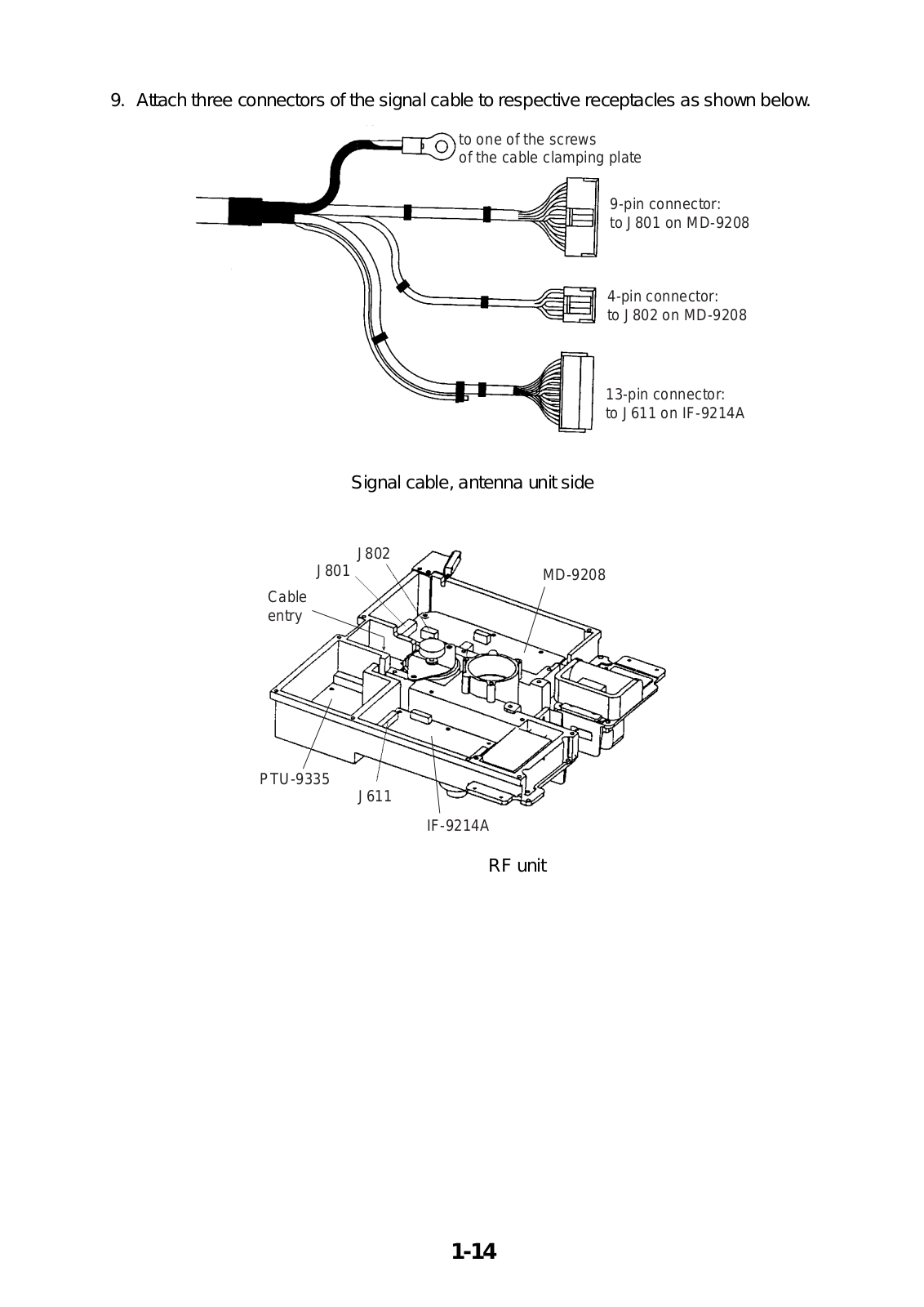
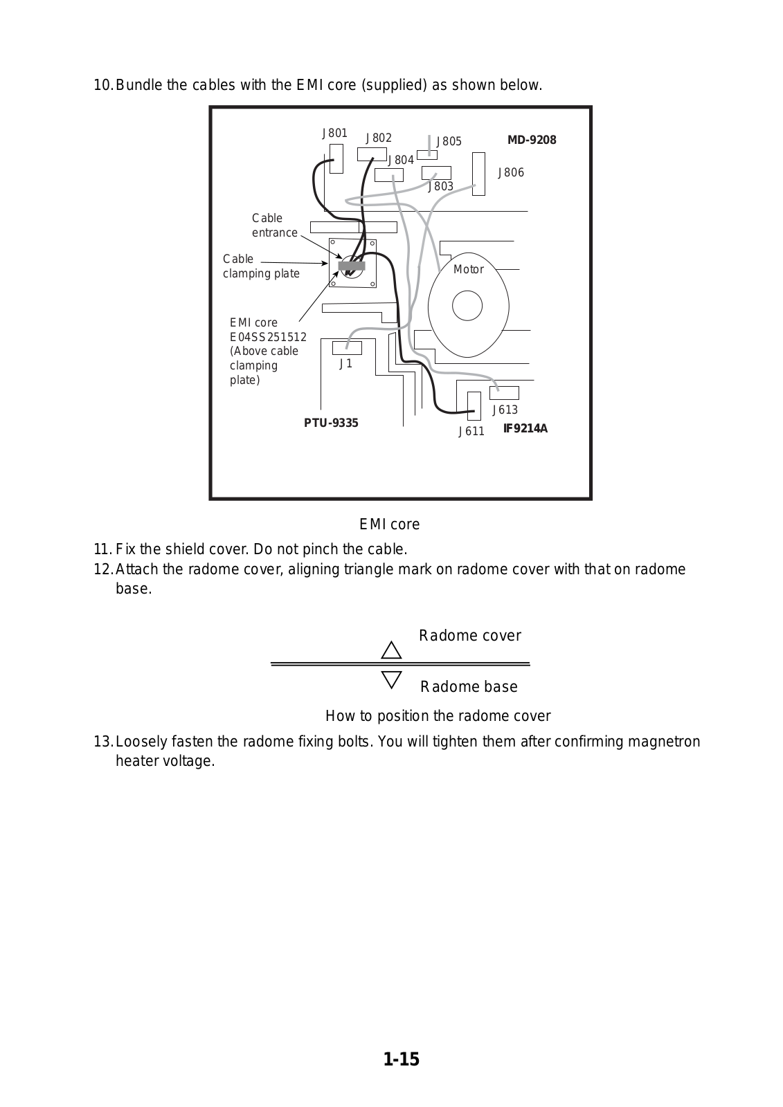
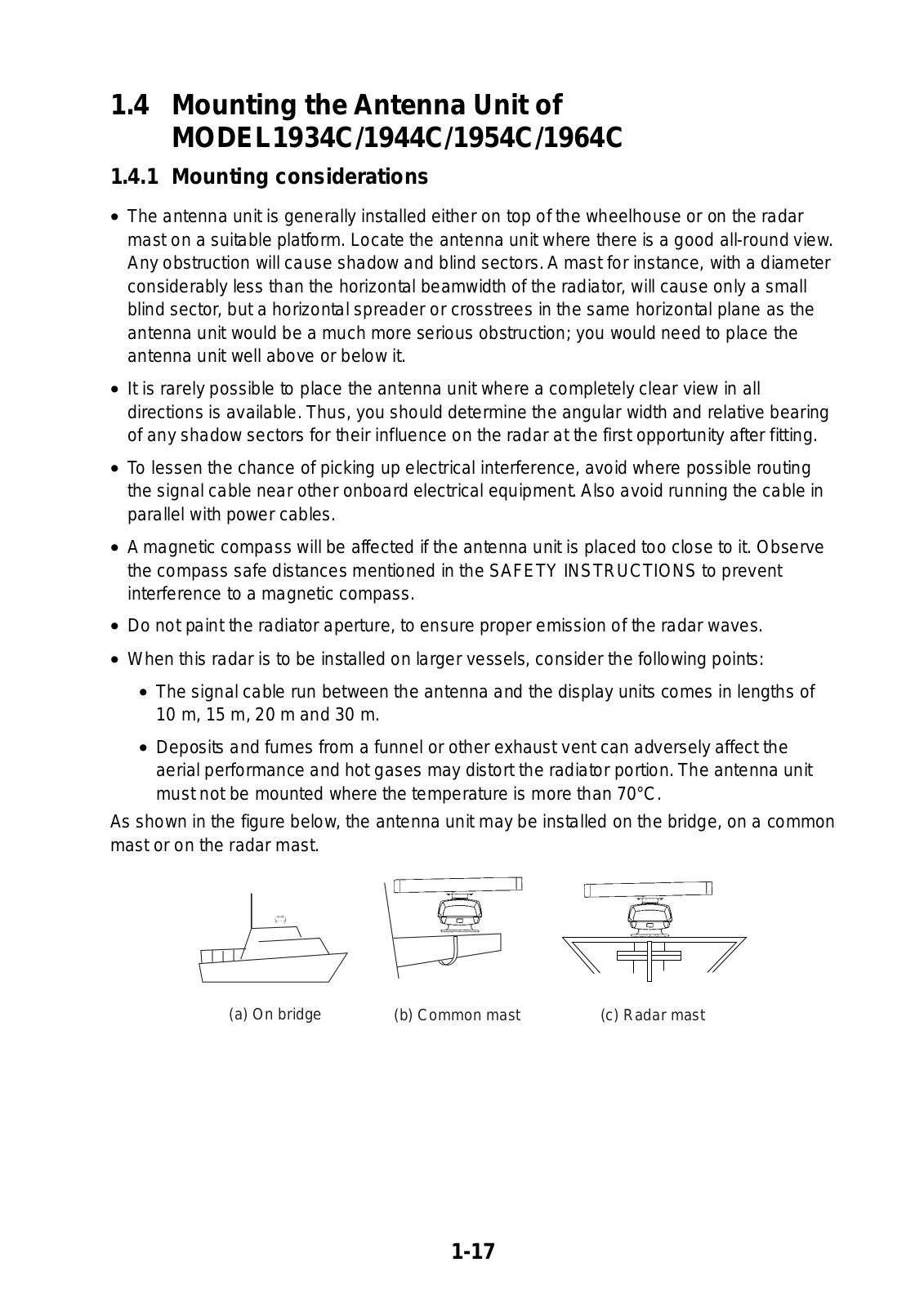
Furuno
Loading...
F
FR1500MK3
3
fr2130s
2
fr8100d
FR/FAR-2835SW/2865SW
FRS-1000
2
FRS-1000A
FRS-1000B
2
FRS-1000C
2
FS-1501
FS-1502
FS-1503
3
FS-1503EM
fs1550
3
FS-1552
2
FS-1562
3
FS-1562-15
2
FS-1562-25
3
FS-1570
9
FS-1570/2570
FS-1575
11
FS-1575 (150 W)
FS-2570
11
FS-2575
14
FS-2575 (250 W)
FS-5000
3
FS-5070
3
FS-5075
11
FS-5075 (500 W)
FS-5275 250W
FS-8000
4
FSV-24
3
FSV-24S
2
FSV25
2
FSV25S
FSV-2S
FSV-30
2
FSV-30S
FSV-35
4
FSV-35S
FSV-84
3
FSV-85
5
FSVB-35S
FV-110
FW-200
G
GD-1700
GD-1700C
3
GD-1710C
2
GD-1720C
2
gd188
2
GD-1900C
4
GD-1900C-BB
2
GD-1920C
5
GD-1920C-BB
6
GD-280
GD-3100
2
GD-3100 Mark-2
2
GD-3300
GD-380
GD-680
GD-8540
GN-8615
GN-86F
GN-8715
GN-87F
GP-1250
GP-150
10
GP-150/DUAL
4
GP-1600F
3
GP-1610C
GP-1610CF
2
GP-1640
GP-1640F
GP-1650
3
GP-1650D
5
GP-1650DF
2
GP-1650F
4
GP-1650W
3
GP-1650WD
4
GP-1650WDF
3
GP-1650WF
3
GP-1670
3
GP-1800
2
GP-1800F
GP-1810
3
GP-1810F
2
GP-1850
4
GP-1850D
5
GP-1850DF
4
GP-1850F
3
GP-1850 Series
GP-1850W
4
GP-1850WD
3
GP-1850WDF
3
GP-1850WF
4
GP-185F
GP-1870
3
GP-1870F
11
GP-1871F
2
GP-188
3
GP-1971F
2
Loading...
Loading...
Nothing found
GD-1920C
Operator's Manual
295 pgs
8.57 Mb
0
User Manual
239 pgs
4 Mb
0
Installation Manual
88 pgs
4.34 Mb
0
Operator's Manual
4 pgs
197.43 Kb
0
User Manual
92 pgs
4.15 Mb
0
Table of contents
Loading...
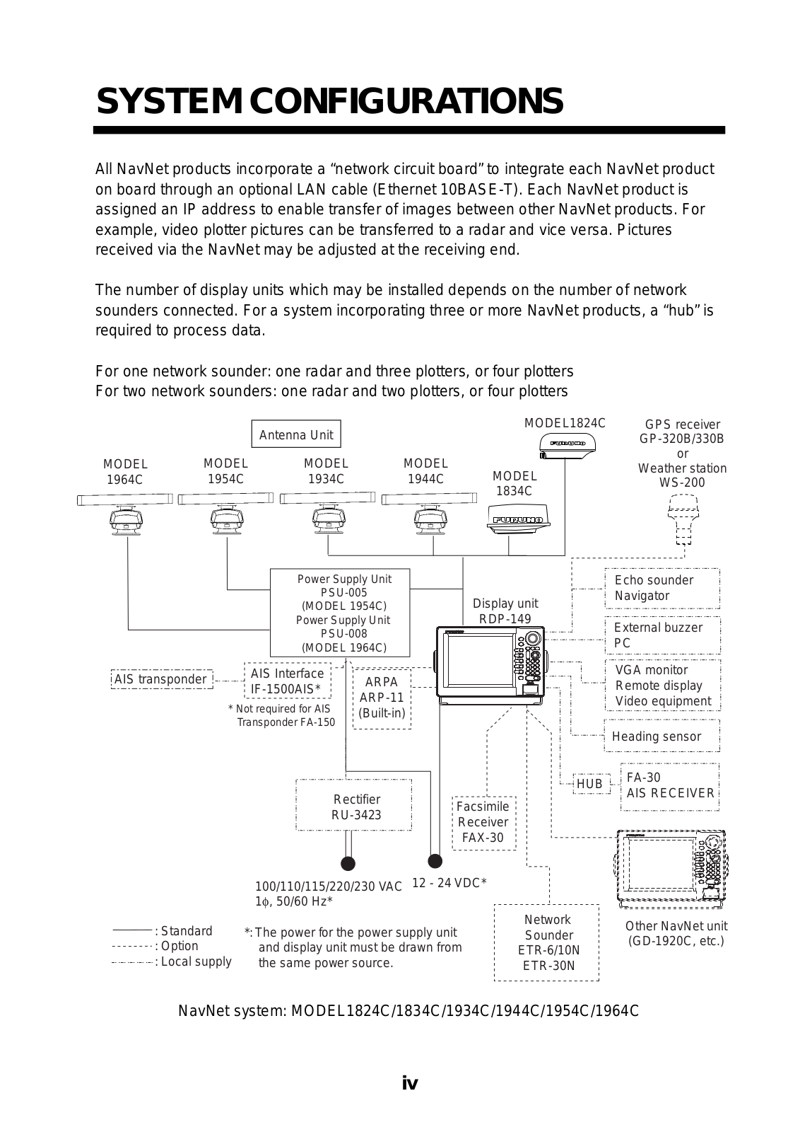
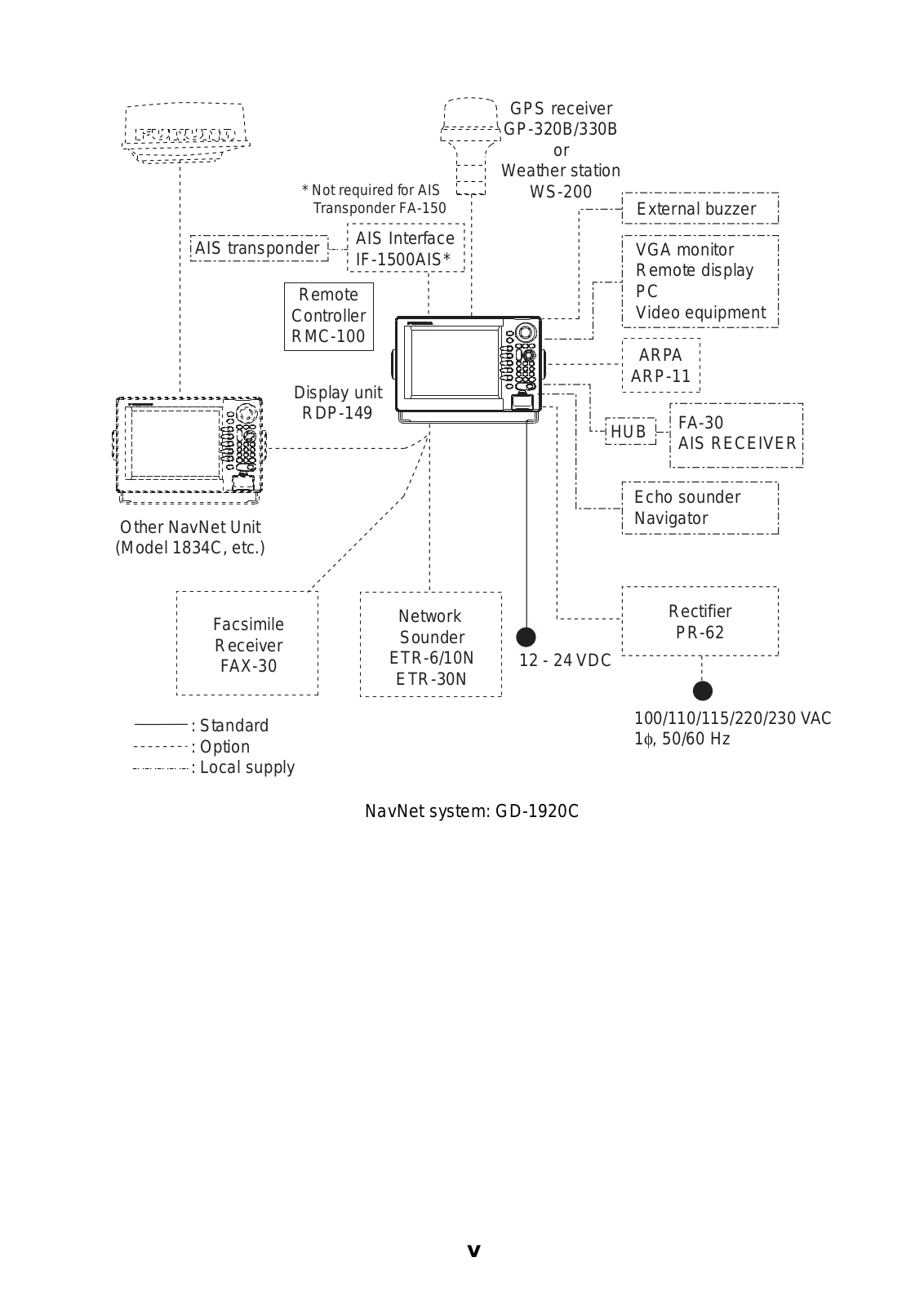
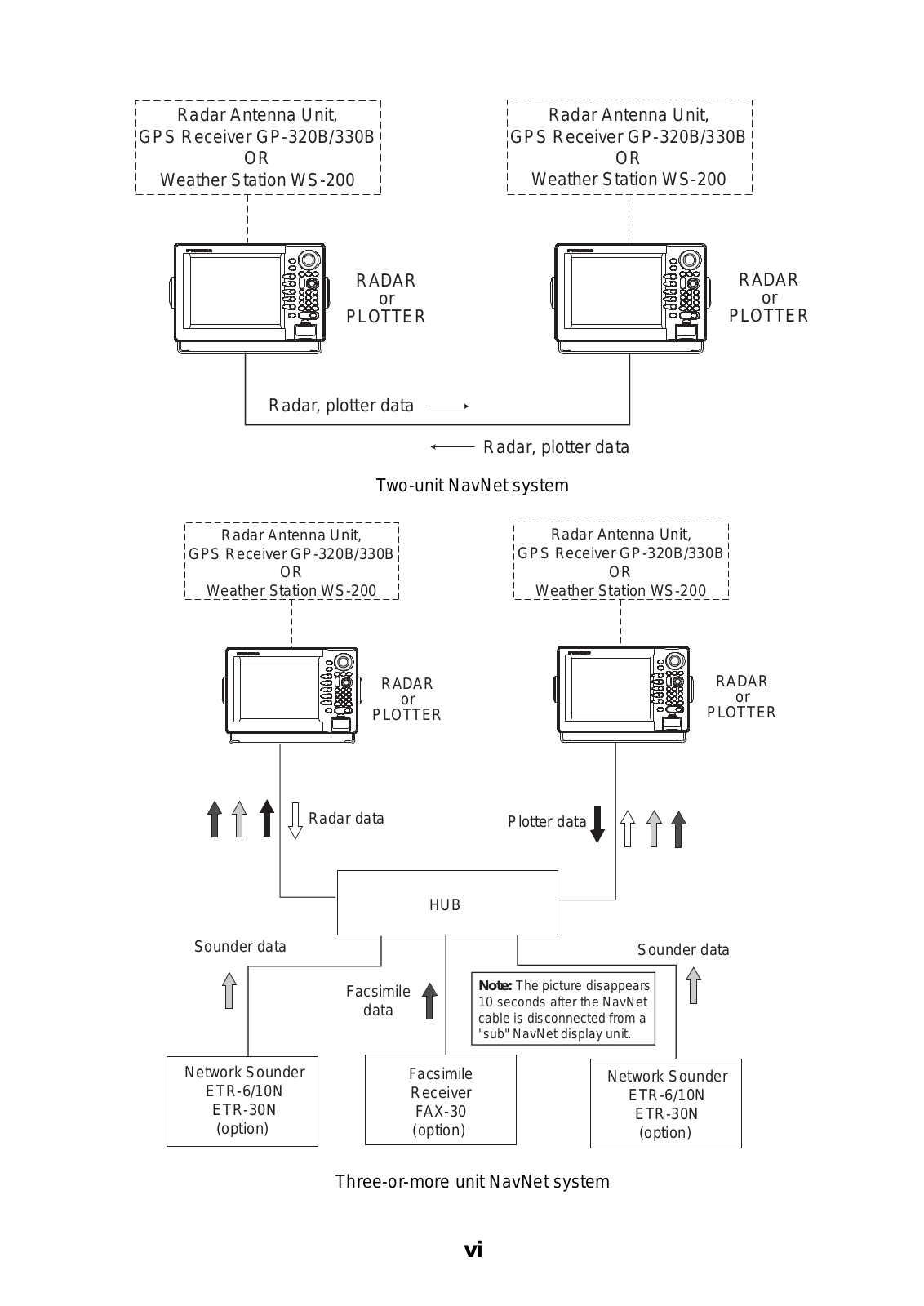
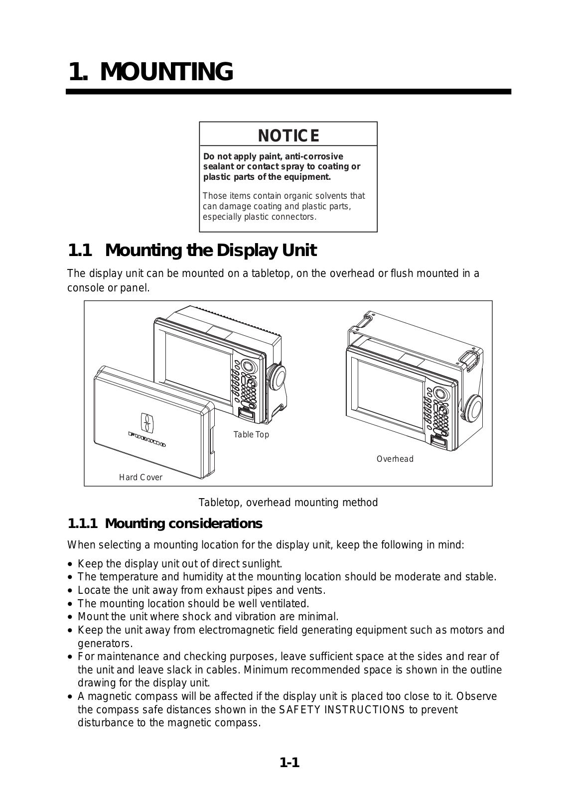
Furuno GD-1920C User Manual
...
Furuno User Manual
Download
Specifications and Main Features
Frequently Asked Questions
User Manual
Download
Loading...
+
64
hidden pages
Unhide
You need points to download manuals.
1 point = 1 manual.
You can buy points or you can get point for every manual you upload.
Buy points
Upload your manuals
 Loading...