

Page 1

COLOR VIDEO PLOTTER GD-1700C
COLOR VIDEO PLOTTER GD-1710C
VIDEO PLOTTER GD-1700
Page 2

9-52 Ashihara-cho,9-52 Ashihara-cho,
x
A
A
*00080918402**00080918402*
*00080918402**00080918402*
*OME44090H00**OME44090H00*
Nishinomiya, JapanNishinomiya, Japan
Telephone :Telephone : 0798-65-21110798-65-2111
faxfa
ll rights reserved.
ll rights reserved.
PUB.No.PUB.No. OME-44090OME-44090
0798-65-42000798-65-4200
::
Printed in JapanPrinted in Japan
Your Local Agent/DealerYour Local Agent/Dealer
IRST EDITION :
IRST EDITION : APR.APR. 20012001
HH :: APR.APR. 09,200409,2004
(( HIMAHIMA ))
GD-1700/1700C/1710CGD-1700/1700C/1710C
* 0 0 0 8 0 9 1 8 4 0 2 ** 0 0 0 8 0 9 1 8 4 0 2 *
*OME44090H00**OME44090H00*
* O M E 4 4 0 9 0 H 0 0 ** O M E 4 4 0 9 0 H 0 0 *
Page 3

SAFETY INSTRUCTIONS
WARNING
ELECTRICAL SHOCK HAZARD
Do not open the equipment.
Only qualified personnel
should work inside the
equipment.
Do not disassemble or modify the
equipment.
Fire, electrical shock or serious injury can
result.
Immediately turn off the power at the
switchboard if the equipment is emitting
smoke or fire.
Continued use of the equipment can cause
fire or electrical shock. Contact a FURUNO
agent for service.
CAUTION
No one navigation device should ever be
solely replied upon for the navigation of
a vessel.
Always confirm position against all available
aids to navigation, for safety of vessel and
crew.
A warning label is attached to the equipment. Do not remove the label. If the
label is missing or damaged, contact
a FURUNO agent or dealer about
replacement.
WARNING
To avoid electrical shock, do not
remove cover. No user-serviceable
parts inside.
Name: Warning Label (1)
Type: 86-003-1011-0
Code No.: 100-236-230
Keep heater away from equipment.
A heater can melt the equipment's power
cord, which can cause fire or electrical
shock.
Use the proper fuse.
Fuse rating is shown on the power cable.
Use of a wrong fuse can result in damage
to the equipment.
NOTICE
The brilliance of the LCD is adjustable
to match a wide variety of lighting
conditions. However, its maximum
setting may not be sufficiently bright
to permit viewing of the display with
polarized sunglasses.
i
Page 4

TABLE OF CONTENTS
FOREWORD ...............................................................................................................viii
SYSTEM CONFIGURATIONS........................................................................................x
WHAT IS WAAS?.........................................................................................................xii
1. OPERATIONAL OVERVIEW..................................................................................1-1
1.1 Operating Controls ......................................................................................................................1-2
1.1.1 Display unit controls .......................................................................................................1-2
1.1.2 Remote controller ...........................................................................................................1-5
1.2 Inserting a Chart Card.................................................................................................................1-6
1.3 Turning the Unit On/Off ...............................................................................................................1-7
1.4 Display Brilliance, Panel Brilliance, Contrast, Hue......................................................................1-8
1.4.1 Displ a y brilliance, panel bril lia nc e...................................................................................1-8
1.4.2 Contrast ..........................................................................................................................1-9
1.4.3 Hue (GD-1700C/1710C).................................................................................................1-9
1.5 Selecting a Display....................................................................................................................1-10
1.5.1 Display modes..............................................................................................................1-10
1.5.2 Selecting a display........................................................................................................1-11
1.5.3 Switching control in combination and overlay screens.................................................1-12
1.5.4 Selecting image source ................................................................................................1-13
1.6 Cursor Pad, Cursor ...................................................................................................................1-14
1.7 Entering the MOB Mark, Setting MOB as Destination ..............................................................1-15
1.8 Data Boxes................................................................................................................................1-16
1.8.1 Showing, hiding data boxes with soft key.....................................................................1-16
1.8.2 Rearranging data boxes ...............................................................................................1-16
1.8.3 Temporarily erasing a data box ....................................................................................1-16
1.9 Function Keys............................................................................................................................1-17
1.9.1 Executing a function .....................................................................................................1-17
1.10 Simulation Display.....................................................................................................................1-18
2. PLOTTER OPERATION.........................................................................................2-1
2.1 Plotter Displays ...........................................................................................................................2-1
2.1.1 Full-screen plotter display...............................................................................................2-1
2.1.2 Compass display ............................................................................................................2-3
2.1.3 Highway display..............................................................................................................2-5
2.1.4 Nav data display.............................................................................................................2-6
2.2 Presentation Mode ......................................................................................................................2-7
2.2.1 North-up..........................................................................................................................2-7
2.2.2 Course-up.......................................................................................................................2-8
2.2.3 Auto course-up ...............................................................................................................2-8
2.3 Shifting the Display......................................................................................................................2-9
2.4 Chart Scale..................................................................................................................................2-9
2.5 Chart Cards...............................................................................................................................2-10
2.5.1 Chart card overview......................................................................................................2-10
2.5.2 Indices and chart enlargement.....................................................................................2-11
ii
Page 5

2.5.3 FURUNO and NavChartsTM charts...............................................................................2-12
2.5.4 C-MAP charts...............................................................................................................2-14
2.6 Working with Track....................................................................................................................2-18
2.6.1 Displaying track............................................................................................................2-18
2.6.2 Stopping, restarting plotting of own ship track..............................................................2-19
2.6.3 Changing track color (GD-1700C/1710C)....................................................................2-20
2.6.4 Track plotting method and interval for own ship track..................................................2-21
2.6.5 Changing own ship track/mark distribution setting.......................................................2-22
2.6.6 Erasing track.................................................................................................................2-23
2.7 Marks, Lines..............................................................................................................................2-25
2.7.1 Entering a mark, line.....................................................................................................2-25
2.7.2 Changing mark attributes .............................................................................................2-25
2.7.3 Selecting line type ........................................................................................................2-26
2.7.4 Erasing marks, lines .....................................................................................................2-27
2.8 Waypoints..................................................................................................................................2-29
2.8.1 Entering waypoints.......................................................................................................2-29
2.8.2 Editing waypoint data ...................................................................................................2-32
2.8.3 Erasing waypoints ........................................................................................................2-34
2.8.4 Changing waypoint mark size (FURUNO, NavCharts
TM
).............................................2-35
2.8.5 Searching waypoints ....................................................................................................2-36
2.9 Routes.......................................................................................................................................2-37
2.9.1 Creating routes.............................................................................................................2-37
2.9.2 Connecting routes ........................................................................................................2-41
2.9.3 Insertin g wa ypoints in a route.......................................................................................2-42
2.9.4 Removing waypoints from a route................................................................................2-44
2.9.5 Erasing routes ..............................................................................................................2-44
2.10 Navigation .................................................................................................................................2-45
2.10.1 Navigating to a "quick point".........................................................................................2-45
2.10.2 Navigating to waypoints................................................................................................2-46
2.10.3 Navigating to ports, port services (NavCharts
TM
only)..................................................2-47
2.10.4 Following a route..........................................................................................................2-49
2.10.5 Cancelling route navigation..........................................................................................2-52
2.11 Alarms.......................................................................................................................................2-53
2.11.1 Audio alarm on/off ........................................................................................................2-53
2.11.2 Arrival alarm .................................................................................................................2-54
2.11.3 Anchor watch alarm......................................................................................................2-55
2.11.4 XTE (Cross Track Error) alarm.....................................................................................2-56
2.11.5 Speed alarm .................................................................................................................2-56
2.11.6 Proximity alarm.............................................................................................................2-57
2.11.7 Trip alarm......................................................................................................................2-58
2.11.8 Alarm information .........................................................................................................2-59
2.12 Resetting Trip Distance.............................................................................................................2-60
3. RADAR OPERATION ............................................................................................3-1
3.1 Radar Display..............................................................................................................................3-1
3.2 Transmitting, Stand-by ................................................................................................................3-2
3.3 Tuning .........................................................................................................................................3-2
3.4 Adjusting the Gain.......................................................................................................................3-2
iii
Page 6

3.5 Reducing Sea Clutter..................................................................................................................3-4
3.5.1 Ho w the A/C SEA works.................................................................................................3-4
3.5.2 Adjusting A/C SEA..........................................................................................................3-4
3.6 Reducing Precipitation Clutter.....................................................................................................3-5
3.6.1 Adjusting the A/C RAIN ..................................................................................................3-5
3.6.2 Adjusting the FTC...........................................................................................................3-6
3.7 Range Scale................................................................................................................................3-7
3.8 Pulselength..................................................................................................................................3-8
3.9 Presentation Mode ......................................................................................................................3-9
3.9.1 Selecting a presentation mode .......................................................................................3-9
3.9.2 Description of presentation modes...............................................................................3-10
3.10 Measuring the Range................................................................................................................3-12
3.10.1 Measuring range by range rings...................................................................................3-12
3.10.2 Measuring range by cursor...........................................................................................3-13
3.10.3 Measuring range by VRM.............................................................................................3-14
3.10.4 Erasing a VRM, VRM indication ...................................................................................3-15
3.10.5 Erasing EBL/VRM data boxes......................................................................................3-15
3.10.6 Hiding EBL/VRM data boxes........................................................................................3-15
3.10.7 Moving EBL/VRM data boxes.......................................................................................3-15
3.11 Measuring the Bearing..............................................................................................................3-15
3.11.1 Measuring bearing by cursor........................................................................................3-15
3.11.2 Measuring bearing by EBL ...........................................................................................3-15
3.11.3 Erasing an EBL, EBL indication....................................................................................3-16
3.11.4 Erasing EBL/VRM data boxes......................................................................................3-16
3.11.5 Hiding EBL/VRM data boxes........................................................................................3-16
3.11.6 Moving EBL/VRM data boxes.......................................................................................3-16
3.12 Erasing the Heading Line, North Marker...................................................................................3-17
3.13 Reducing Noise.........................................................................................................................3-17
3.14 Reducing Radar Interference....................................................................................................3-18
3.15 Zoom .........................................................................................................................................3-19
3.15.1 Zooming in on radar targets..........................................................................................3-19
3.15.2 Zooming in on ARP, TTM targets..................................................................................3-19
3.16 Shifting the Picture ....................................................................................................................3-20
3.16.1 Manual shift ..................................................................................................................3-20
3.16.2 Automatic shift ..............................................................................................................3-21
3.17 Using the Offset EBL.................................................................................................................3-22
3.17.1 Predicting collision course............................................................................................3-22
3.17.2 Measuring range & bearing between t wo targets.........................................................3-23
3.18 Echo Trails.................................................................................................................................3-24
3.18.1 Trail time.......................................................................................................................3-24
3.18.2 Starting echo trails........................................................................................................3-25
3.18.3 Trail brilliance (GD-1700)..............................................................................................3-25
3.18.4 Trail gradation (GD-1700C/1710C) ..............................................................................3-25
3.18.5 Trail color (GD-1700C/1710C)......................................................................................3-26
3.19 Echo Stretch..............................................................................................................................3-27
3.20 Echo Averaging .........................................................................................................................3-28
3.21 Outputting TLL Data ..................................................................................................................3-29
iv
Page 7

3.22 Guard Alarm..............................................................................................................................3-30
3.22.1 Setting a guard alarm zone ..........................................................................................3-30
3.22.2 When the alarm is violated… .......................................................................................3-31
3.22.3 Cancelling the guard alarm ..........................................................................................3-31
3.23 Watchman.................................................................................................................................3-32
3.23.1 How watchman works...................................................................................................3-32
3.23.2 Turning on/off watchman..............................................................................................3-32
3.23.3 Setting watchman stand-by interval .............................................................................3-32
3.24 Waypoint Marker .......................................................................................................................3-33
3.25 ARP, TTM Operation .................................................................................................................3-34
3.25.1 Activating/deactivating ARP, TTM.................................................................................3-35
3.25.2 Acquiring and tracking targets (ARP)...........................................................................3-36
3.25.3 Displaying target number (ARP, TTM)..........................................................................3-37
3.25.4 Terminating tracking of ARP targets.............................................................................3-38
3.25.5 Setting vector attributes (ARP).....................................................................................3-39
3.25.6 Displaying past position display (ARP).........................................................................3-40
3.25.7 ARP, TTM target data...................................................................................................3-41
3.25.8 CPA/TCPA alarm (ARP) ...............................................................................................3-42
3.25.9 Lost target alarm (ARP)................................................................................................3-43
3.26 Interpreting the Radar Display ..................................................................................................3-44
3.26.1 General.........................................................................................................................3-44
3.26.2 False echoes ................................................................................................................3-46
3.26.3 SART (Search and Rescue Transponder)....................................................................3-48
3.26.4 Racon (Radar Beacon).................................................................................................3-50
4. VIDEO SOUNDER OPERATION ........................................................................... 4-1
4.1 Principle of Operation..................................................................................................................4-1
4.2 Sounder Displays........................................................................................................................4-2
4.2.1 Selecting a sounder display ...........................................................................................4-2
4.2.2 Description of sounder displays .....................................................................................4-3
4.2.3 Selecting screen split method in combination displays..................................................4-7
4.3 Automatic Sounder Operation.....................................................................................................4-8
4.3.1 How the automatic sounder works.................................................................................4-8
4.3.2 Types of automatic sounder modes ...............................................................................4-8
4.3.3 How to enable automatic sounder operation..................................................................4-8
4.4 Manual Sounder Operation.........................................................................................................4-9
4.4.1 Selecting the manual mode............................................................................................4-9
4.4.2 Selecting display range ..................................................................................................4-9
4.4.3 Adjusting the gain...........................................................................................................4-9
4.4.4 Range shifting...............................................................................................................4-10
4.5 Measuring Depth, Time.............................................................................................................4-11
4.6 Reducing Interference...............................................................................................................4-12
4.7 Reducing Low Level Nois e ........................................................................................................4-13
4.8 Erasing Weak Echoes...............................................................................................................4-14
4.9 White Marker (GD-1700C/1710C) ............................................................................................4-15
4.10 Picture Advance Speed.............................................................................................................4-16
4.10.1 Advancement independent of ship's speed..................................................................4-16
4.10.2 Advancement synchronized with ship's speed.............................................................4-17
v
Page 8

4.11 Display Colors (GD-1700C/1710C)...........................................................................................4-18
4.12 Alarms .......................................................................................................................................4-19
4.12.1 Audio alarm on/off.........................................................................................................4-19
4.12.2 Bottom alarm ................................................................................................................4-20
4.12.3 Fish alarm.....................................................................................................................4-20
4.12.4 Fish alarm (B/L) ............................................................................................................4-21
4.12.5 Water temperature alarm..............................................................................................4-22
4.12.6 When an alarm setting is violated.................................................................................4-23
4.13 Water Temperature Graph.........................................................................................................4-24
4.14 Changing Pluse Repetitio n Rate ...............................................................................................4-24
4.15 Interpreting the Sounder Display...............................................................................................4-25
4.15.1 Zero line........................................................................................................................4-25
4.15.2 Bottom echo..................................................................................................................4-25
4.15.3 Fish school echoes.......................................................................................................4-26
4.15.4 Surface noise/Aeration .................................................................................................4-26
5. CUSTOMIZING YOUR UNIT..................................................................................5-1
5.1 General Setup .............................................................................................................................5-1
5.2 Plotter Setup................................................................................................................................5-4
5.2.1 Navigation options..........................................................................................................5-4
5.2.2 Function key setup..........................................................................................................5-5
5.3 Chart Setup .................................................................................................................................5-7
5.3.1 Chart offset.....................................................................................................................5-7
5.3.2 FURUNO, NavCharts
5.3.3 C-MAP chart attributes .................................................................................................5-11
5.4 Data Boxes Setup .....................................................................................................................5-15
5.5 Hot Page Setup.........................................................................................................................5-16
5.6 Navigator Setup.........................................................................................................................5-17
5.6.1 Navigation data source.................................................................................................5-17
5.6.2 GPS receiver setup (Set equipped with GP-310B/320B).............................................5-18
5.6.3 TD display setup...........................................................................................................5-22
5.7 Nav Data Display Setup ............................................................................................................5-24
5.8 Radar Setup ..............................................................................................................................5-25
5.8.1 Radar display setup......................................................................................................5-25
5.8.2 Function key setup........................................................................................................5-28
5.9 Sounder Setup ..........................................................................................................................5-30
5.9.1 System setup................................................................................................................5-30
5.9.2 Sensor setup.................................................................................................................5-32
5.9.3 Sounding range, zoom range, bottom lock range ........................................................5-33
5.9.4 Function key setup........................................................................................................5-34
TM
chart attributes.........................................................................5-8
6. DATA TRANSFER..................................................................................................6-1
6.1 Memory Card Operations............................................................................................................6-1
6.1.1 Formatting memory cards...............................................................................................6-1
6.1.2 Saving data to a memory card........................................................................................6-2
6.1.3 Playing back data from a memory card..........................................................................6-4
6.2 Uploading, Downloading Data.....................................................................................................6-5
6.2.1 Setting communication software on the PC....................................................................6-5
6.2.2 Uplo ad ing or download ing data......................................................................................6-5
vi
Page 9

6.3 Loading Waypoint Data from Y eoman.....................................................................................6-8
6.4 Receiving Data Via Network Equipment.................................................................................. 6-9
6.5 Outputting Data Through the Network...................................................................................6-10
7. MAINTENANCE, TROUBLESHOOTING...............................................................7-1
7.1 Preventive Maintenance.........................................................................................................7-1
7.2 Replacement of Fuse.............................................................................................................7-2
7.3 Replacement of Batteries.......................................................................................................7-2
7.4 Simple Troubleshooting..........................................................................................................7-3
7.4.1 General......................................................................................................................7-3
7.4.2 Plotter........................................................................................................................7-3
7.4.3 Radar.........................................................................................................................7-4
7.4.4 Sounder.....................................................................................................................7-5
7.5 Diagnostics............................................................................................................................7-6
7.5.1 Memory I/O test.........................................................................................................7-6
7.5.2 Test pattern................................................................................................................7-9
7.5.3 Keyboard, remot e c ontroller test...............................................................................7-10
7.6 GPS Status Display..............................................................................................................7-11
7.7 Clearing Memories...............................................................................................................7-12
7.8 Error Messages....................................................................................................................7-13
APPENDIX..................................................................................................................A-1
Menu Overview............................................................................................................................ A-1
Geodetic Chart List ...................................................................................................................... A-9
World Time Chart........................................................................................................................A-10
Icons ........................................................................................................................................ A-11
SPECIFICA TIONS.................................................................................................... SP-1
INDEX...................................................................................................................Index-1
vii
Page 10

FOREWORD
A Word to the Owner of the GD-1700/1710 Series
Video Plotter
FURUNO Electric Company thanks you for purchasing the GD-1700/1710 Series Video
Plotter. We are confident you will discover why the FURUNO name has become
synonymous with quality and reliability.
For over 50 years FURUNO Electric Company has enjoyed an enviable reputation for
quality and reliability throughout the world. This dedication to excellence is furthered by our
extensive global network of agents and dealers.
Yo ur plotter is designed and constructed to m eet t he rigorous demands of the marine
environment. However, no machine can perform its intended function unless properly
installed and maintained. Please carefully read and follow the operation and maintenance
procedures set forth in this manual.
We would appreciate feedback from you, the end-user, about whether we are achieving our
purposes.
Thank you for considering and purchasing FURUNO.
The example screens shown in this manual may not match the screens you see on your
display. The screen you see depends on your system configuration and equipment settings.
viii
Page 11

Features
The 1700 series wor k within our new pr oduc t-network system c alled the “NavNet.” Each
product has an IP addr es s to communicate wit h NavN et compatible products within the
network, using TCP/IP protocol through an Ethernet 10BASE-T netw ork.
The mai n features are as f ollows:
• Three models are available:
GD-1700: Monochrome LCD
GD-1700C: Color LCD
GD-1710C: High-precision color LCD
• Bright 7” screen visible even under direct s unlight.
• User-friendly oper ation with combination of di s c rete k eys, sof t keys and cursor pad.
• Accepts FURUNO an d NavChart s ™ ( NAVIONICS) c har ts, or C- MAP NT/NT+ charts
(C-MAP), depending on s pec ification.
All names ment ioned are registered trademarks of thei r r espec tive companies.
• Fast chart redraw.
• Built-in NavNet interface ci r c uit board.
• 12-channel GPS Rec eiver GP-310B with highly accurate position fixing opt ionally
available, GP-320B with WAAS capability .
• User programmable f unc tion key s .
• Radar picture available with connection to NavNet com patible radar.
• Video sounder picture avail able wi th connection of the optional Network S ounder
ETR-6/ 10N or E TR-30N.
• Optional memory c ar d interface unit CU-200.
ix
Page 12
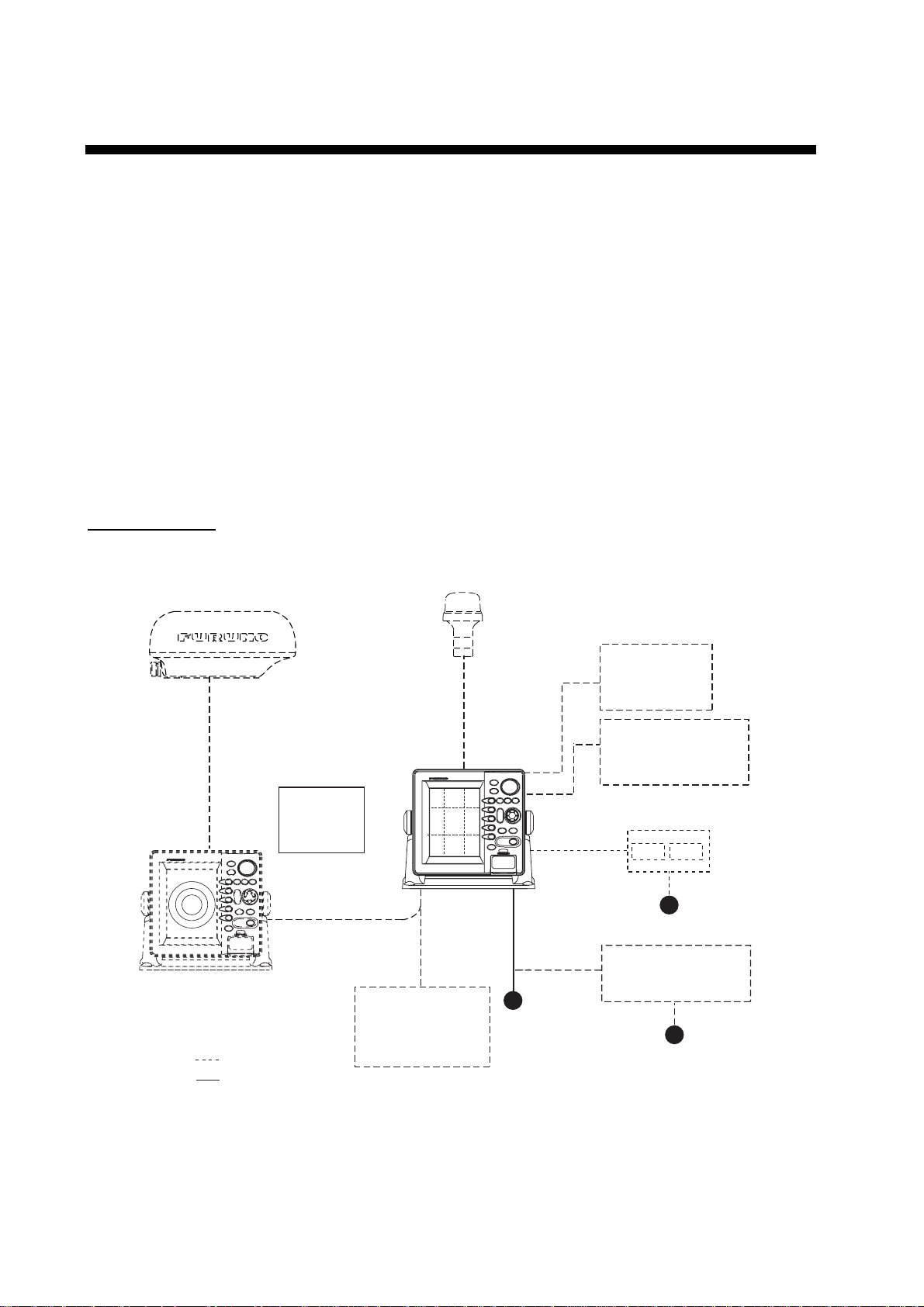
SYSTEM CONFIGURATIONS
All NavNet products incorporate a “network circui t board” to integrate each NavNet product
on board through an optional LAN cable (Ethernet 10BASE-T). Each NavNet product is
assigned an IP addr es s to enable transfer of images between other NavNet products . For
example, video plott er pictures can be t r ans ferr ed to a radar and vice versa. Pictures
received vi a t he NavNet may be adjusted at the receiving end.
The number of display units which may be installed depends on the number of
networ k s ounder connecte d. For a sy s tem incorporati ng three or more product s ,
a “hub” is requi r ed to process data.
For one network sounder: one radar and three plotters, or four plott er s
For two network sounder: one radar a nd two plot ters, or four plotters
NavNet system
Antenna Unit
(ex. MODEL 1722/1722C/1723C)
DisplayUnit
GD-1710C
GD-1700C
GD-1700
Remote
Controller
RMC-100
Other NavNet Unit
(Model 1722, etc.)
: Option
: Standard
Network Sounder
ETR-6/10N
ETR-30N
GPS Receiver
GP-310B/320B
12-24 VDC
100/110/115/220/230VAC,
φ
1
Echo sounder
Navigator
Echo sounder
External buzzer
PC
Memory card
interface unit CU-200
12 VDC
Rectifier
PR-62
,50/60Hz
NavNet system
x
Page 13
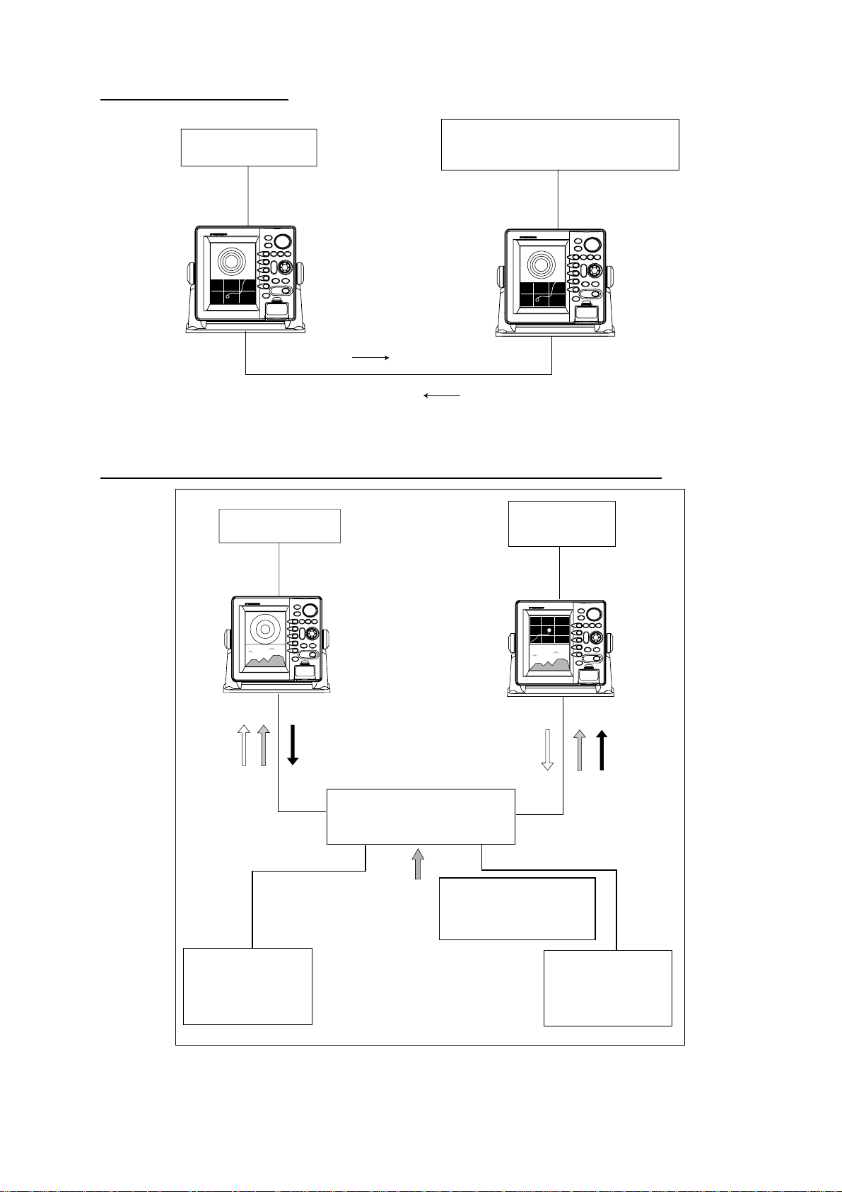
Two-unit NavN et system
Radar Antenna Unit
GPS Receiver GP-310B/320B
PLOTTER
Radar data
Plotter data
Two-unit NavNet system
Three-or-mo re-uni t NavNet system (Max. 4 NavNet capable display u nits)
Antenna Unit
GP-310B/320B
Radar data
HUB
Sounder data
Network Sounder
ETR-6/10N
ETR-30N
(option)
Plotter data
Note: The picture disappears
10 seconds after the NavNet
cable is disconnected from a
"sub" NavNet display unit.
Network Sounder
ETR-6/10N
ETR-30N
(option)
Three-or-more-unit NavNet system
xi
Page 14
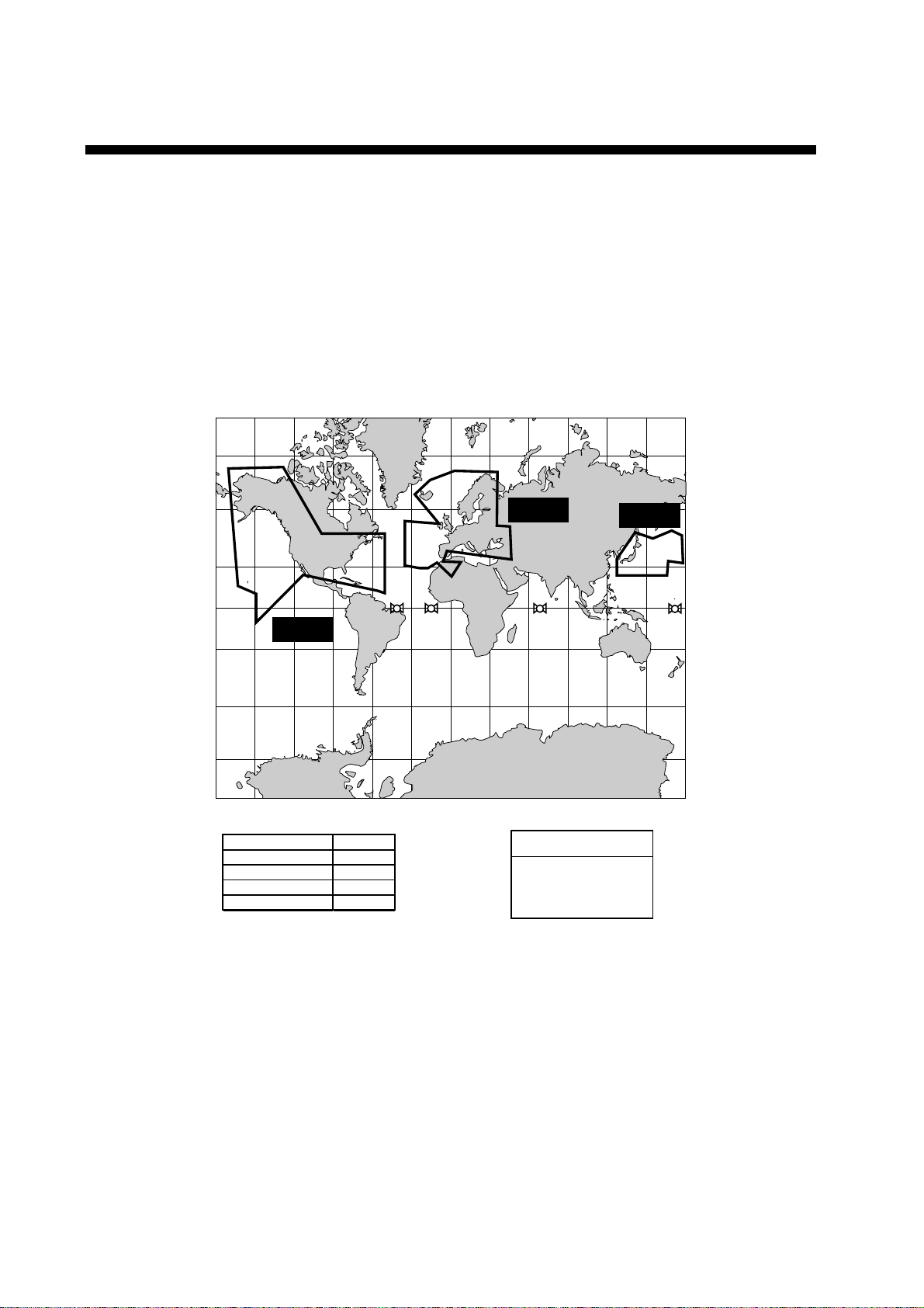
WHAT IS WAAS?
WAAS, available in North America, is a provider in the worldwide SBAS (Satellite
Based Augmentation System) navigation system. SBAS provides GPS signal
corrections to SBAS users, for even better position accuracy, typically better
than three meters. Two more SBAS providers are also currently under
development, MSAS (Multi-F unct ional Satellit e Augmentation System) for Japan
and EGNOS (Eur o Geostat ionary Navigation O v er lay Servi c e) for Europe. All
providers w ill be compatible with one another, thus providing “ s eam less” pos ition
fixes to SBAS users. The illustration below shows the coverage area. (Accuracy
may be affected w hen us ing a GEO satellit e not within your c ur r ent locati on. )
150°W 120°W 90°W 60°W 30°W 0 30°E 60°E 90°E 120°E 150°E
60
°
N
°
N
60
°
N
134
40
20
°
N
0
40
20
0
°
N
°
N
120
122
EGNOS
131
MSAS
WAAS
°
S
20°S
40
°
S
60
°
S
150°W 120°W 90°W 60°W 30°W 0 30°E 60°E 90°E 120°E 150°E
Satellite, Region Position
120, AOR-E
122, AOR-W
131, IOR
134, POR
15.5°W
54°W
64.5°E
178°E
Initial operation time
WAAS: 2003
EGNOS: 2004
MSAS: 2005
20
40
°
S
60
°
S
At the time of this software release, SBAS is still under development (Providers
are expected to have initial operations cap ability from the times shown above.)
During thi s developmental period, whi c h m ay last for several years, ther e is no
guarantee of t he accuracy, integrity, continuity, or availability of the SBAS signal.
Furuno w ill accept no responsibi lity for the use of the signal for other than the
above stat ed purpose. It is the user' s r es ponsibi lity to exercise common
prudence and navi gational judgment w hile using the SBAS signal. Users are
reminded that the SBAS has not been commi ssioned for use i n saf ety of life
applicat ions (SOLAS ) and mus t be turned t o the "OFF" position on any SOLA S
vessels.
xii
Page 15

1. OPERATIONAL OVERVIEW
This chapter provides basic information needed to get you started using your
plotter. The following topics are presented:
• Control overview
• Chart card insertion
• Power on/off
• Contrast, brilliance and hue (GD-1700C/1710C only) adjustments
• Display selection
• MOB (Man OverBoard) mark entry
• Data boxes
• Function keys
• Simulation display
1-1
Page 16
1. OPERATIONAL OVERVIEW
1.1 Operating Controls
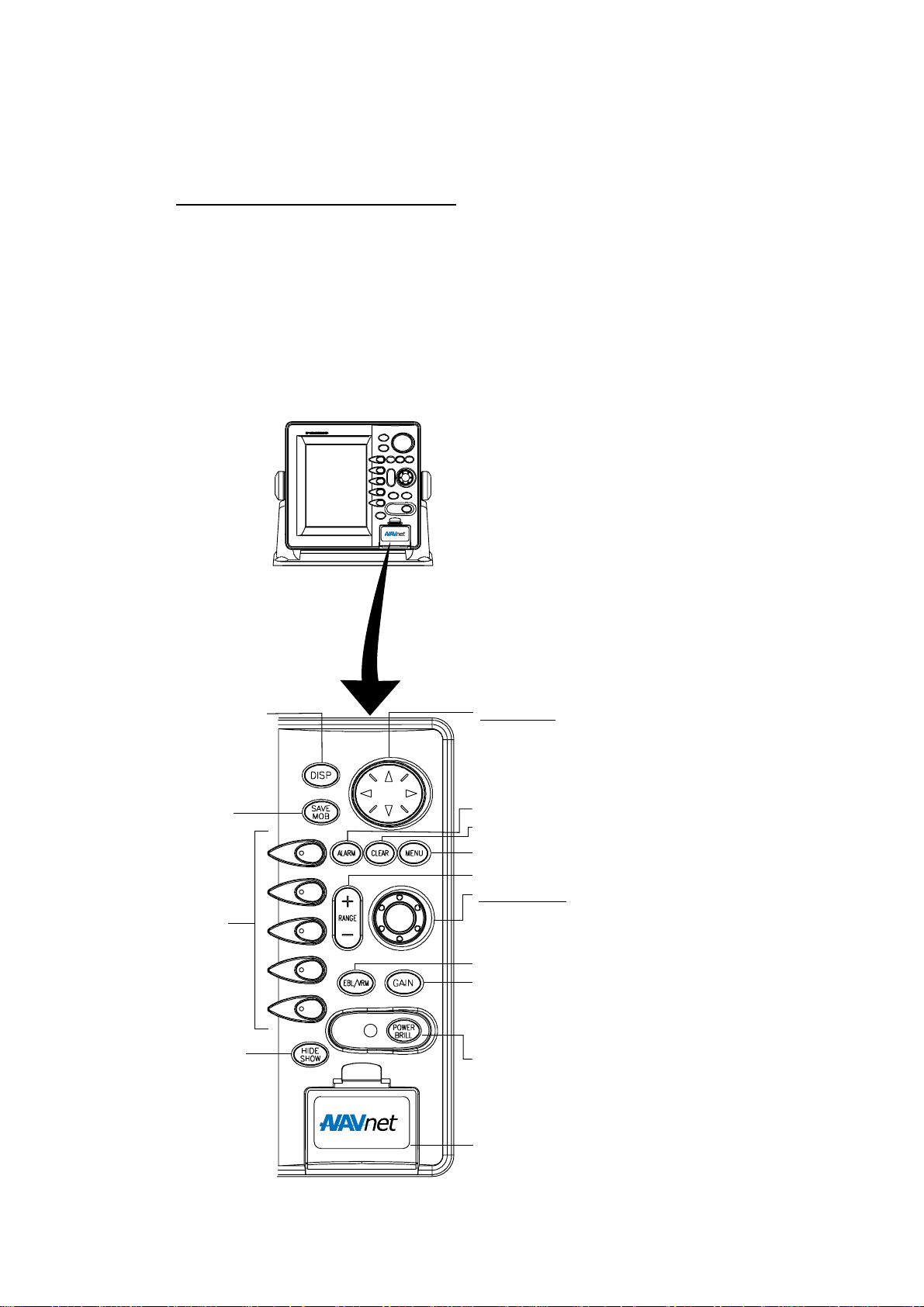
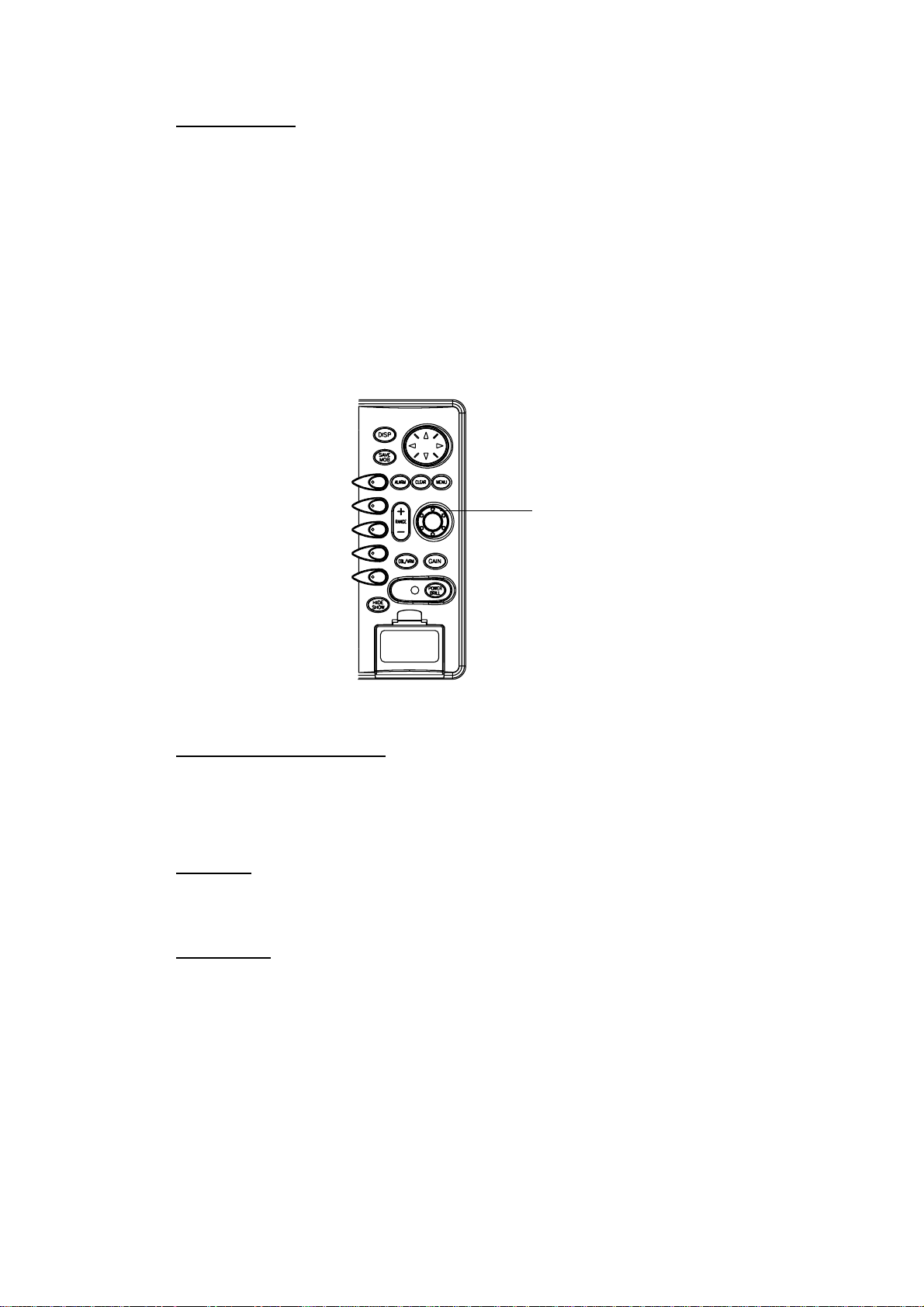
1.1.1 Display unit controls
Overview of display u nit control s
The plotter, radar, sounder and chart systems are mainly operated with controls
of the display unit (and remote controller). Ten keys are labeled and they provide
the function shown on their labels. The five soft keys provide various functions
according to current operating mode. The [ENTER] knob mainly functions to
register selections on the menu and enter alphanumeric data. The cursor pad’s
main function is to move the cursor across the screen. When you correctly
execute an operation, the unit generates a beep. Invalid operation causes the
unit to emit three beeps.
Selects display mode.
Momentary press:
Registers own ship’s
position as a waypoint.
Press three seconds:
Marks man overboard
position.
Soft keys
Shows or hides the soft
keys, function keys,
nav data alternately.
Cursor pad
Selects menu items and options;
shifts cursor. Press, release and
press again to change setting
consecutively.
Opens/closes the alarm menu.
Clears data; erases selected mark.
Opens/closes the main menu.
Selects a range.
ENTER knob
Push: Registers options on menus.
Rotate: Selects character; adjusts sensitivity
(sounder, radar); chooses menu items and options.
Displays the soft keys for EBL/VRM.
Radar: Displays the soft keys for adjustment of
gain, A/C SEA, A/C RAIN and FTC (Model 1700
series radar only).
Sounder: Adjusts gain.
Long press: Turns power off.
Momentary press: Turns power on;
opens the display for adjustment of brilliance,
etc.; displays RADAR STBY/TX soft key.
Chart slot
1-2
Control p anel
Page 17
1. OPERATIONAL OVERVIEW
Soft keys
The function of the five soft keys changes according to the operation. Their
labels for their current functions are shown on the screen to t he left of the keys.
To hide or show the soft key labels, press t he [HIDE/SHOW] key. Each press of
the key shows preset soft keys, user function keys or turns off navigation
information (at the top of the screen).
SOFT
KEYS
Display unit
Some soft keys show the current state of the soft key function in reverse video
as shown below.
34° 22. 3456'N 359.9°M
080° 22. 3456'E
16.0nm
WPT 002
FISH
BRIDGE
19.9 kt 99.9 nm
TRIP
NU
MARK
ENTRY
MODE
NTH UP
NAV
POS
D.BOX
ON/OFF
Current option
shown in reverse video
Plotter display
1-3
Page 18
1. OPERATIONAL OVERVIEW
[ENTER] knob
The [ENTER] knob functions to
• Register data
• Enter alphanumeric data such as waypoint name
• Select menu items and options
• Adjust setting
For data input, clockwise rotation of the knob selects an alphabet, symbol or
numeric, in one of the sequences shown below. After you have selected desired
alphanumeric character push the [ENTER] knob to register your selection.
[ENTER] knob
ENTER knob
Alphabet, s y mbol, num er ic
A!B!C!D!E!F!G!H!I!J!K!L!M!N!O!P!Q!R!S!T!U!V!W
!X!Y!Z!&!_!’ !#!0!1!2!3!4!5!6!7!8!9
Numerics
0!1!2!3!4!5!6!7!8!9
Cursor p ad
1-4
The cursor pad’s main function is to shift the cursor. For details see, paragraph
1.6.
Page 19

1.1.2 Remote controller
ABC
RANGE
1
DISP
DEF
1. OPERATIONAL OVERVIEW
Operating distance
90°: Up to 5 m
±45°: Up to 3 m
SAVE
Replace the batteries (AA) when the
MOB
distance from which the display
unit can be operated shortens.
32
GHI
JKL
4
MNO
Note: The remote controller may
65
PQR
become damaged if dropped.
Mishandling of the remote
STU
7
VWX
98
YZ&
controller is not covered by
the warranty.
0
MENU
TX /STBY
ALARM
SK4 SK5
GAIN
CENTER
CNTL
ACQ
HIDE /SHOW
EBL / VRM
MARK
ENT
BRILL
WPT
’#
ENT
CLEAR
TONE
SK3SK1 SK2
Remote controller
Key Function Key Function
RANGE Same as RANGE key on
display unit.
DISP Same as DISP key on
display unit.
SAVE MOB Same as SAVE MOB key on
display unit.
Ten keys Enter alphanumerics. BRILL Adjusts display brilliance.
EBL/VRM Same as EBL/VRM key on
display unit.
GAIN Same as GAIN key on
display unit.
WPT Displays “alphabet” WPT list
on plotter display.
MARK ENT Same as MARK ENTRY soft
key.
CENTER Returns own ship to screen
center on plotter display.
CNTL Switches control between
displays on combination
displays.
ENT Same as ENTER knob on
display unit.
CLEAR Same as CLEAR key on
display unit.
MENU Same as MENU key on
display unit.
TONE Adjusts display contrast
(color model only).
TX/STBY Toggles radar between
standby and transmit.
ACQ Acquires radar target.
(Requires radar source
equipped with ARP.)
ALARM Same as ALARM key on the
display unit.
HIDE/SHOW Same as HIDE/SHOW key
on display unit.
SK1 – SK5
(soft keys)
Same as soft keys on display
unit.
1-5
Page 20

1. OPERATIONAL OVERVIEW
1.2 Inserting a Chart Card
Your unit reads FURUNO and NavCharts™ (NAVIONICS) chart cards, or
C-MAP chart cards, depending on t he type of display unit you have. Insert the
appropriate chart card f or your area as follows:
1. Open the chart c ard slot lid.
Chart slot
Display unit Memory card interface unit
2. Insert des ired chart card gr oove side up.
3. Close the l id to protect the chart drive.
Note 1: Do not remove a card while the chart is being drawn. This may c aus e
the equipme nt to freeze.
Note 2: Do not insert or rem ov e a c ard while the power is on. This may c aus e
the equipme nt to freeze.
Note 3: For multiple display uni ts, do not use t he s am e c hart card t ype in more
than one dis play uni t.
Note 4: A c ar d rem over is suppl ied to ease removal of char t cards. Attach the
card remover to the right - hand side hole on the card and pull to remove
card. You can leave the c ard remover attached to the card while the
card is i n the card slot - push the c ar d r emover leftw ar d until it contact s
the recesse d ar ea in the car d.
Card drive
(option)
1-6
Chart card and c ard remov er
Page 21
1.3 Tu rning the Unit On/Off
Press the [POWER/BRILL] key to turn the unit on. A beep sounds and the
equipment proceeds in the sequence shown below, displaying the production
information screen, startup test results and the chart usage disclaimer. The
startup test checks the ROM, RAM, internal battery and backup data f or proper
operation, displaying the results for each as OK or NG (No Good). If NG appears
an appropriate message appears on the screen. For any NG, try to press any
key to go to the chart disclaimer screen, then perf orm the diagnostic test
referring to the paragraph “7.5 Diagnostics.”
1. OPERATIONAL OVERVIEW
Host Name
Chart List
GD-1700(C) PLOTTER
STATION NAME:
PLOTTER*
FURUNO ELECTRIC CO., LTD.
CHARTS AVAILABLE
LICENSE NO.
GD-1700C
C-MAP: 03591720XX
NAVIONICS: 03591730XX
* = Name determined at installation.
STARTUP TEST
ROM OK
RAM OK
BACKUP DATA OK
è
INTERNAL BATTERY OK
GD-1710C
C-MAP: 03591960XX
NAVIONICS: 03591970XX
XX= Program Version No.
NO NATIONAL HYDROGRAPHIC
OFFICE HAS VERIFIED THE
INFORMATION IN THIS
COASTLINE DATA CARD AND NONE
ACCEPT LIABILITY FOR THE
ACCURACY OF REPRODUCTION OR
ANY MODIFICATIONS MADE
THEREAFTER. THIS PRODUCT WITH
è
THIS COASTLINE DATA CARD
DOES NOT REPLACE THE
REQUIREMENT TO USE THE
APPROPRIATE PRODUCTS FOR
NAVIGATION ACCORDING TO
NATIONAL AND INTERNATIONAL
REGULATIONS.
PROGRAM No.
Product information Startup test Chart disclaimer
Startup sequence
Yo u may press any key at the chart disclaimer screen to show the last-used
display, or wait several seconds to let the equipment do it for you. For start up
with the radar display, t he magnetron takes from one minute to two minutes
and thirty seconds (depending or radar model) to warm up bef ore t he radar can
be operated. The time remaining for warm up of the magnet ron is counted down
at the center of the display.
To turn the unit off, press and hold down the [POWER/BRI LL] key until the
display goes dark (about 3 sec.). To protect the LCD attach the hard cover. Note
that the network sounder is turned off approx. three minutes aft er turning off the
power.
Note: The first time you turn on the power (or any time the power is applied after
a memory reset), you are asked if you want to start the simulat ion mode,
which provides simulated operation of the equipment. Push the [ENTER]
knob to start the simulation mode, or press the [CLEAR] key to start
normal operation. For details about the simulation mode, see the
paragraph “1.10 Simulation Display.”
GD-1700
C-MAP: 03591700XX
NAVIONICS: 03591710XX
(See above)
1-7
Page 22
1. OPERATIONAL OVERVIEW
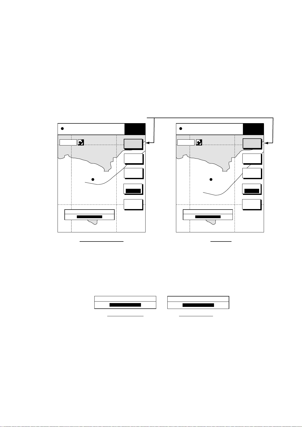
1.4 Display Brilliance, Panel Brilliance, Contrast, Hue
Yo u can adjust display brilliance, panel brilliance, contrast and hue
(GD-1700C/1710C only) as shown below.
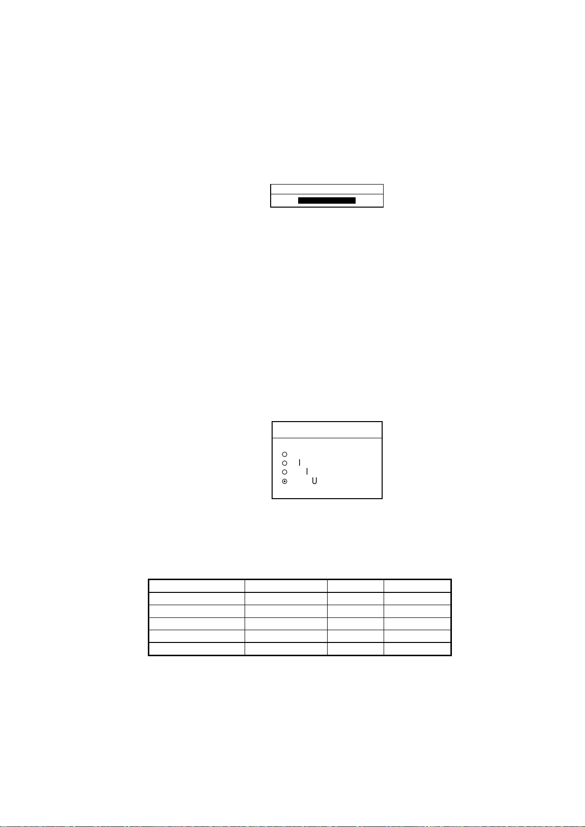
1.4.1 Display brilliance, panel brilliance
1. Press t he [ P OWER/BRILL] key momentarily. A set of soft keys for adjustment
of brilliance, contrast and hue (GD-1700C/1 710C only) appear.
Current selection is highlighted.
34° 22. 3456'N 359.9°M TRIP N
080° 22. 3456'E
19.9 kt 99.9 nm
BRILL
CONTST
34° 22. 3456'N 359.9°M TRIP
080° 22. 3456'E
19.9 kt 99.9 nm
BRILL
CONTST
16.0nm
DISPLAY BRILLIANCE
DISPLY
BRILL
PANEL
BRILL
CONTST
/HUE
RADAR
STBY
RETURN
8
16.0nm
DISPLAY BRILLIANCE
8
GD-1700C/1710C GD-1700
Brilliance adjustment soft keys
2. Press the DISPLY BRILL or PA NEL BRILL soft key as appropriate. An
adjustment window appears at the bottom of the screen. This window shows
the name of the item selected for adjustment plus current brilliance level, by
bar graph.
DISPLY
BRILL
PANEL
BRILL
CONTST
RADAR
STBY
RETURN
DISPLAY BRILLIANCE
8
Display brilliance Panel brilliance
PANEL BRILLIANCE
8
Display brilliance and panel brilliance windows
3. Adj ust the [ENTER] knob, clockwise to raise the setting or counterclockwise
to decrease it. You may also use the soft key pressed at step 2. Eight levels
of display brilliance and panel brilliance are available.
4. Hit the RETURN soft key to finish.
Note: If the equipment is turned off with minimum brilliance the screen will be
dark at the next power up. Press the [POWER/BRILL] key consecutively to
adjust the brilliance.
1-8
Page 23
1.4.2 Contrast
1. Press the [POWER/BRILL] key momentarily.
2. Press the CONTST (GD-1700) or CONTST/HUE (GD-1700C/1710C) soft
key.
3. For the GD-1700C/1710C, two soft keys appear at the pressing of the
CONTST/HUE soft key: CONTST and HUE. Press the CONTST soft key to
adjust the contrast.
4. Adjust the [ENTER] knob, clockwise to raise the setting or counterclockwise
to decrease it. You may also use the CONTST soft key. 16 levels (GD-1700)
and 10 levels (GD-1700C/1710C) of contrast are available.
5. Press the RETURN soft key to finish.
CONTRAST
8
Contrast w indow
1. OPERATIONAL OVERVIEW
1.4.3 Hue (GD-1700C/1710C)
You may select the colors for the radar, plotter and overlay displays as below.
1. Press the [POWER/BRILL] key momentarily.
2. Press the CONTST/HUE (GD-1700C) or HUE (GD-1710C) soft key.
3. Press the HUE soft key to show the hue setting window.
HUE
▲
¡
¡
¡
¤
▼
4. Operate the cursor pad to select hue desired, referring to the table below.
MANUAL SET follows the color settings on the CHART DETAILS menu for
the plotter and RADAR DISPLAY SETUP for the radar.
Night Day Twilight
Characters Red Black Green
Radar ring Red Green* Green*
Radar echo Orange Red Yellow
Background Black White Blue
Landmass (plotter) Light-Yellow Yellow Dim Yellow
* = Red on C-MAP display unit.
DAY
NIGHT
TWILIGHT
MANUAL SET
Hue window
5. Hit the RETURN soft key to finish.
Note: When using the overlay screen (color model only), the own ship track will
be hidden if the radar background and own ship track are blue and the
“MANUAL SET” hue setting is used. In this case, set HUE to other position
and then return to “MANUAL” to show the own ship track in black.
1-9
Page 24
1. OPERATIONAL OVERVIEW
1.5 Selecting a Display
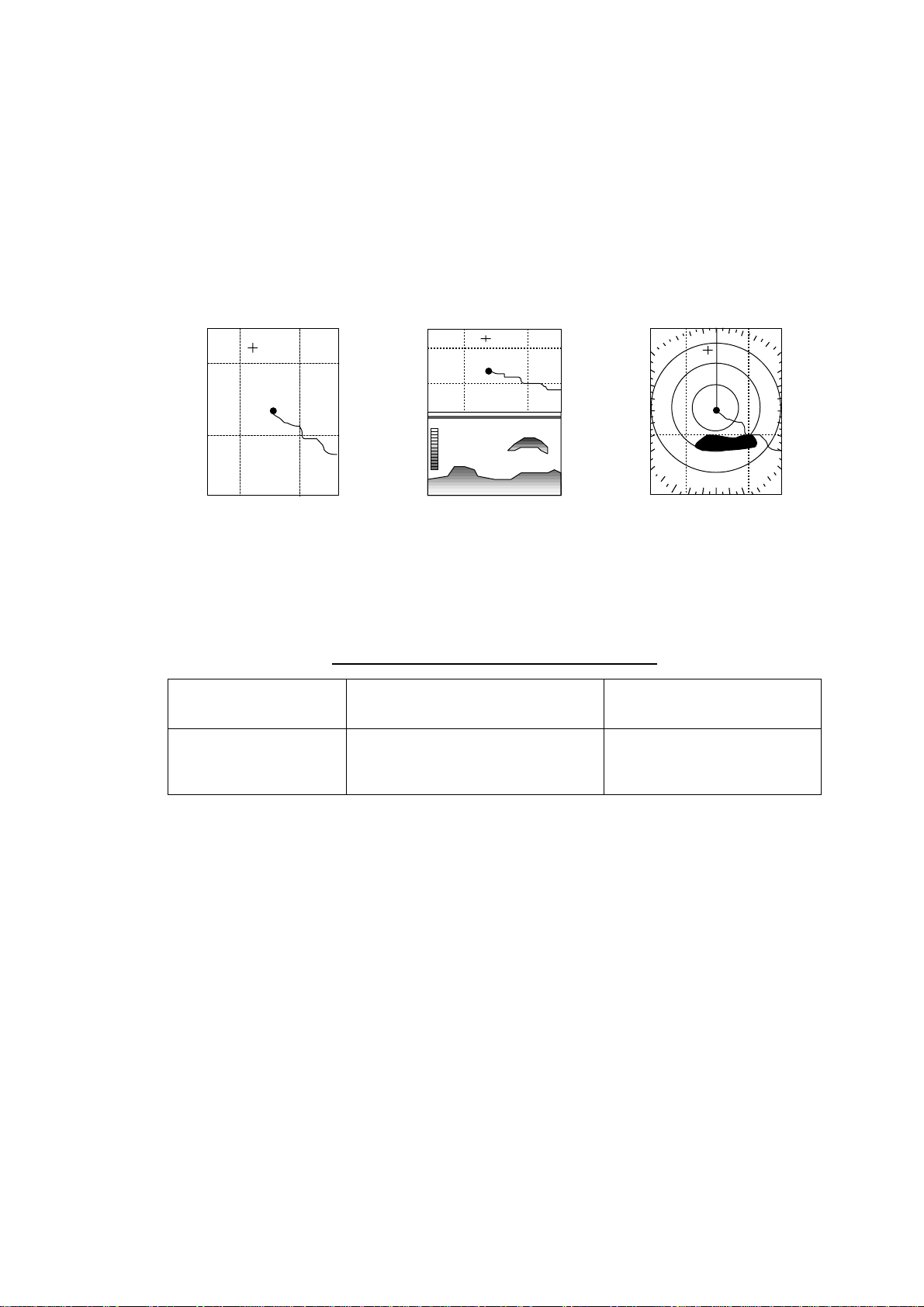
1.5.1 Display modes
If you have a network radar, navigator and network sounder connected, four
full-screen displays are available: plotter, radar, video sounder and navigation
data. (The GD-1700C/1710C has five screens, those mentioned above plus the
overlay screen.) In addition to the full-screen display, you can divide the screen
into half-screen combination displays to show two sets of images (data).
Full screen
(Ex. plotter)
Combination screen
(Ex. plotter + sounder)
Overlay screen
(Radar and plotter,
color model only)
Display screens
The table below shows the displays available with each screen type.
Screen type a nd availabl e display screen
Full screen Combination screen options
Plotter, radar,
sounder, nav data
Plotter, radar, sounder, compass,
highway, compass/highway, nav
data, overlay
Overlay screen options
(GD-1700C/1710C only)
Radar + plotter
1-10
Page 25

1.5.2 Selecting a display
1. Press the [DISP] key to show the full-screen selection window. The icons of
modes not available are marked with an “X.”. PAGE1-PAGE5 are
user-arrangeable displays called “hot pages,” which you can configure as you
like. For further details, see the paragraph “5.5 Hot Page Setup.”
RADAR PLOT SNDR NAV
PAGE1 PAGE2 PAGE3 PAGE4 PAGE5
OVRLY*
1. OPERATIONAL OVERVIEW
Basic display
screens
* = Color model only
Hot pages
· TURN KNOB TO SELECT MODE
AND PUSH KNOB TO ENTER.
· PUSH ANY SOFT KEY TO
SELECT IMAGE SOURCE.
Full-scre en s election window
2. Rotate the [ENTER] knob to select a basic display screen or a hot page
screen.
3. Push the [ENTER] knob. If you selected a basic display screen, a set of
appropriate combination display screens appear. In the example below, radar
combination displays are shown.
PUSH ENTER KNOB.
Radar com bination sc r een s election window
4. Operate the [ENTER] knob to select the combination screen display desired,
then push it to set.
1-1 1
Page 26
1. OPERATIONAL OVERVIEW
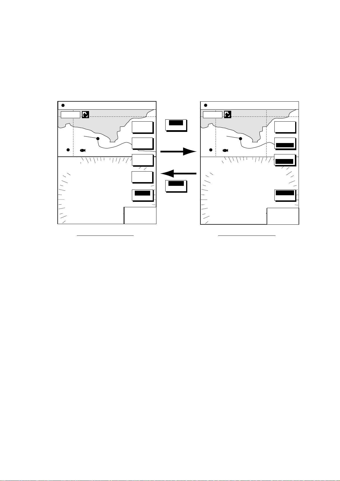
1.5 .3 Switching control in combination and ov erlay screens
A soft key is provided in relevant combination and overlay screens
(GD-1700C/1710C only) to switch control between displays. In the example
below, the RADAR CNTRL and PLOTTR CNTRL soft keys enable switching
control between the radar and plotter screens in the plotter/radar combination
display.
34° 22. 3456'N 359.9°M
080° 22. 3456'E
16.0nm
WP-002
FISH
3nm
12/
LP
H-UP
ST-BY
19.9 kt 99.9 nm
TRIP
SIGNAL
PROC.
RADAR
DISPL Y
NAV
FUNC
T ARGET
RADAR
CNTRL
NU
CNTL
RADAR
RADAR
CNTRL
To adjust
plot
PLOTTR
CNTRL
To adjust
34° 22. 3456'N 359.9°M
080° 22. 3456'E
16.0nm
WP-002
FISH
3nm
12/
LP
H-UP
ST-BY
19.9 kt 99.9 nm
NAV
POS
radar
359.9
°
+
11.70nm
R
359.9
+
11.70nm
Radar display selected Plotter display selected
How to swi tch control between modes in the plotter/radar combination display
TRIP
NU
MARK
ENTRY
MODE
NTH UP
PLOTTR
CCNTRL
°
R
1-12
Page 27
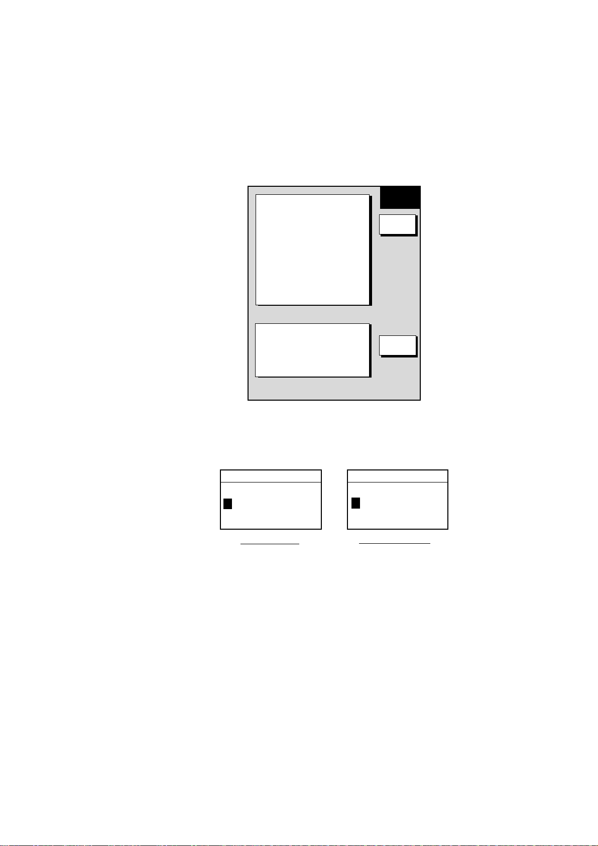
1.5.4 Selecting image source
When more than one network radar or network sounder is connected to the
equipment, you may select an image source for each as shown below. This is
not necessary when only one network radar or network sounder is connected.
1. Press the [DISP] key.
2. Press any soft key to show the following display.
▲
RADAR SOURCE
RADAR
- - -
SOUNDER SOURCE
SOUNDER
IP ADDRESS
172. 031. 014. 001
HOST NAME
PLOTTER -
1. OPERATIONAL OVERVIEW
SELECT
SOURCE
EDIT
-
IF THERE IS MORE THAN
ONE NETWORK RADAR OR
ECHO SOUNDER, YOU MAY
SELECT THE IMAGE
SOURCES FOR DISPLAY.
RETURN
Select source menu
3. Use the cursor pad to select RADAR SOURCE or SOUNDER SOURCE as
appropriate, then press the EDIT key.
RADAR SOURCE SOUNDER SOURCE
RADAR
- - -
Radar source Sounder source
SOUNDER
-
Radar source and sounder s our ce wi ndows
4. Use the cursor pad and [ENTER] knob to enter source name: ◄ or ► to
select position and rotate the [ENTER] knob to select character.
5. Press the ENTER soft key or [ENTER] knob.
6. Press the [DISP] key to finish.
7. Turn the power off and on again.
Note: Source names are determined at installation. For example, the source
names for radars in a two radar system might be “RADAR” and
“RADAR1”.
1-13
Page 28

1. OPERATIONAL OVERVIEW
1.6 Cursor Pad, Cursor
The cursor pad functions to shift the cursor, for measurement of latitude and
longitude position and range and bearing to a location. Press the cursor pad to
turn the cursor on, and the cursor appears at the own ship’s position. Operate
the cursor pad to shift the cursor. The cursor moves in the direction of the arrow
or diagonal pressed on the cursor pad.
Cursor position and range and bearing from own ship to the cursor are displayed
at the top of the screen when the cursor is on.
Cursor data
L/L position,
Range and
bearing from
own ship to
cursor
Cursor
34° 22. 3456'N 272.4°M
+
080° 22. 3456'E
15.9 nm 99.9 nm
16.0nm
Cursor, cursor data
TRIP
NU
MARK
ENTRY
MODE
NTH UP
CENTER
GOTO
CURSOR
D. BOX
ON/ OFF
1-14
Page 29
1. OPERATIONAL OVERVIEW
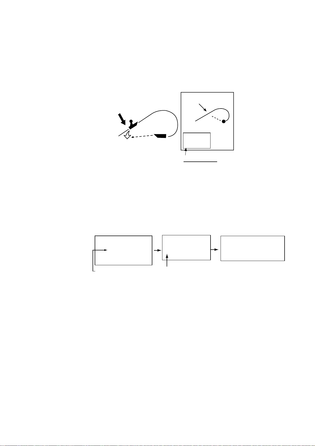
1.7 Entering the MOB Mark, Setting MOB as Destination
The MOB (Man Overboard) mark functions to mark man overboard position. You
can inscribe this mark from any mode, except while playing back data or
conducting any test. Note that this function requires position data.
MOB
Range, bearing
Man
overboad
Current
position
mark
M
O
B
MOB Data Box
Bearing and range
to MOB position
M
(MOB)
162.5°M
0.49 nm
MOB conc ept
1. Press and hold down the [SAVE/MOB] key immediately for about three
seconds when someone falls onboard. The display shows the waypoint
number being saved (youngest empty waypoint number, 001-999) followed
by the MOB confirmation window.
Time remaining is counted down while the [SAVE/MOB] key is pressed.
WAYPOINT SAVED!
XXXWPT
CONTINUE PUSHING
FOR MOB!
XXX = Waypoint number
CONTINUE PUSHING
FOR KNOB!
XX SEC
XX = Time remaining is couted down.
MAN OVER BOARD!
GO TO MOB?
YES ... PUSH ENTER KNOB
NO ... PUSH CLEAR KEY
MOB ma r k mes s ages
2. Push the [ENTER] knob to select the MOB position as the destination, or
press the [CLEAR] key to only mark current ship’s position as a waypoint. If
you select the MOB position as the destination;
• A full-screen radar, plotter or overlay (color model only) appears depending
on the display in use.
• The MOB mark “MOB” appears at the MOB position and a line (light-blue
on the GD-1700C/1710C) runs between it and current position. This line
shows the shortest course to the MOB position.
• Range and bearing to the MOB position are shown in the MOB data box.
To erase an MOB mark fro m the plott er display, you must first erase its
corresponding waypoint. Place the cursor on the MOB mark, then press the
[CLEAR] key followed by pushing the [ENTER] knob to erase the waypoint. Then,
repeat to erase the MOB mark.
1-15
Page 30

1. OPERATIONAL OVERVIEW
1.8 Data Boxes
Data boxes, providing navigation data, may be shown on any full-screen display.
Up to six data boxes (two in case of large characters) may be shown, and the
default data boxes are position (in latitude and longitude), course over ground,
speed over ground and trip log. The user may choose which data to display,
where to locate it, and show or hide it as desired. In addition, data boxes may be
set independently for each display mode (plotter, radar, sounder). For how to
select data for the data boxes, see the paragraph “5.4 Data Boxes Setup”.
34° 22. 3456'N 359.9°M TRIP NU
080° 22. 3456'E
19.9 kt 99.9 nm
SOG
20.0 kt
MARK
ENTRY
MODE
NTH UP
NAV
POS
D.BOX
ON /OFF
16.0nm
002WP
TRIP LOG
4.58
POSITION
°
47
58.535'N
°
122
36.496'W
nm
FISH
COG
BRIDGE
323.6
°
M
Data boxes
Plotter di s play, showing data boxes
1.8.1 Showing, hiding data boxes with soft key
Plotter: D. BOX ON/OFF
Radar: ZOOM & D. BOX
→ D. BOX ON/OFF (EBL/VRM data box, cursor data
box also shown/hidden)
Sounder: AUTO/D. BOX
→D. BOX ON/OFF
1.8.2 Rearranging data boxes
You may select the location for data boxes as follows:
1. Using the cursor pad, place the cursor inside the data box you wish to move.
As the cursor enters the box it changes to a hand. Push the [ENTER] knob,
and the hand changes to a fist, meaning the box is correctly selected.
2. Use the cursor pad to move the data box to the location desired, then push
the [ENTER] knob.
1.8.3 Temporaril y erasi ng a da ta box
You may temporarily erase a data box. Use the cursor pad to place the cursor
inside the data box you wish to erase, then press the [CLEAR] key. To redisplay
the box, press the D.BOX soft key twice to display it.
1-16
Page 31
1.9 Function Keys
The function key s provide f or one-touch execution of a desired func t ion. The
default f unc tion key s ettings are as shown in the table below.
Key
#1 Heading line on/off, HL Track on/off, TRK TLL output, TLL
#2 Rings on/off, RNG Edit mark/line, EML Clutter, CLT
#3 Ech o trail, TRL Ruler, RUL Signal level, SLV
#4 Offcenter, OFC Add new waypoint,
#5 STBY/TX, TX Waypoint
1.9.1 Executing a function
1. Press the [HIDE/SHOW] key to repl ac e the preset s oft key labels with the
function k ey labels.
Radar Plotter Echosounder
1. OPERATIONAL OVERVIEW
Default Setting, Key Label Function
Noise limiter, NL
ADD
Picture advance, PA
alphanumeric list, ALP
34° 22. 3456'N 359.9°M
080° 22. 3456'E
16.0nm
002WP
FISH
BRIDGE
Plotter Radar
2. Press funct ion key desired.
Note: Funct ion keys c an be individual ly program m ed for the plot ter, radar and
sounder dis plays. For further details, detail s see t he following:
Plotter : paragraph 5.2.2
Radar: p ar agr aph 5.8.2
Sounder: paragrap h 5.9.4
19.9 kt 99.9 nm
TRIP
NU
T
R
K
E
M
L
R
U
L
A
D
D
A
L
p
Function
keys
.125nm
SP
.250/ 319.9
H-UP
Function k ey s
°M
TARGET
359.9°R
+
0.24nm
H
L
R
N
G
T
R
L
O
F
C
T
X
Function
keys
1-17
Page 32

1. OPERATIONAL OVERVIEW
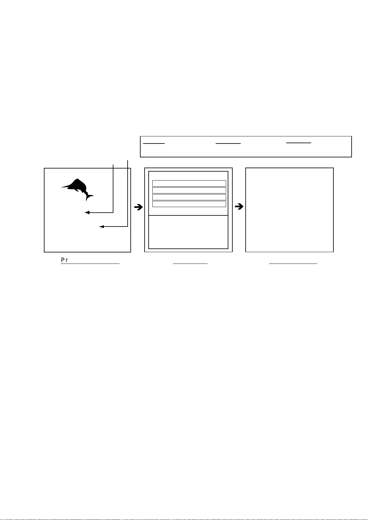
1.10 Simulation Display
The simulation display, which is for use by service technicians for demonstration
purposes, provides simulated operation to help acquaint you with the many
features your unit has to offer. It allows you to view and control a simulated
plotter, radar and sounder picture, without position-fixing equipment, network
radar or a network sounder. Most controls are operative, thus you may practice
setting destination, enter waypoints, etc.
The “SIM” icon (
1. Press the [MENU] key.
2. Press the SYSTEM CONFIGURATION, SYSTEM SETUP and SIMULATION
SETUP soft keys in order.
S
I
M
) appears when any simulation mode is active.
RADAR
LIVE
PLOTTER
LIVE
SOUNDER
LIVE
SPEED
00.0kt
COURSE
000.0
LATITUDE
LONGITUDE
START DATE & TIME
RADAR SIMULATION DATA
°
45
°
35.000’N
125
°
00.000’W
00:00 01.APR.00
NO
SIM
SETUP
EDIT
RETURN
Simulation setup menu
3. Follow appropriate procedure on the next several pages.
Radar
The radar simulation mode is not available with the GD-1700 series.
1-18
Page 33

1. OPERATIONAL OVERVIEW
Plotter
1. Select PLOTTER, then press the EDIT soft key.
PLOTTER
▲
¡
¡
SIMULATION
¤
LIVE
▼
2. Select SIMULATION, then press the [ENTER] knob.
3. Select SPEED, then press the EDIT soft key.
4. Enter speed (setting range, 0-99 kt, default speed, 0 kt) with the
alphanumeric keys, then push the [ENTER] knob.
5. Select COURSE, then press the EDIT key.
6. Select “8 FIGURE” to trace the simulated ship’s track in a figure-eight course,
or enter your own course at DIRECTION. To enter course, use the cursor
pad to select digit, and enter value with the alphanumeric keys.
7. Press the ENTER soft key.
8. Select LATITUDE, then press the EDIT soft key.
9. Enter latitude (setting range, 85
°N-85°S, default setting, 45°35.000’N), then
push the [ENTER] knob.
10. Select LONGITUDE, then press the EDIT soft key.
11. Enter longitude (setting range, 180
°E-180°W, default setting, 125°00.000’W),
then push the [ENTER] knob.
12. Select START DATE & TIME, then press the EDIT soft key.
13. Enter start date and time, then push the [ENTER] knob.
14. Press the [MENU] key to close the menu.
1-19
Page 34

1. OPERATIONAL OVERVIEW
Sounder
1. Select SOUNDER, then press the EDIT soft key.
2. Select SIMULATION 1 (internally generated echoes) or SIMULATION 2
(network sounder-generated echoes), then press the [ENTER] knob.
Note 1: If the network sounder could not be found “Sounder source is not
found. Cannot get simulation data.” appears. And if the sounder is
not active, the message “Sounder is not active. Cannot get
simulation data.” is displayed. Check that the sounder signal cable is
firmly fastened.
SOUNDER
▲
¡
SIMULATION 1
¡
SIMULATION 2
¤
LIVE
▼
Note 2: The gain, shift, range and mode of the SIMULATION 1 mode picture
cannot be adjusted.
3. Press the [MENU] key to close the menu.
1-20
Page 35

2. PLOTTER OPERATION
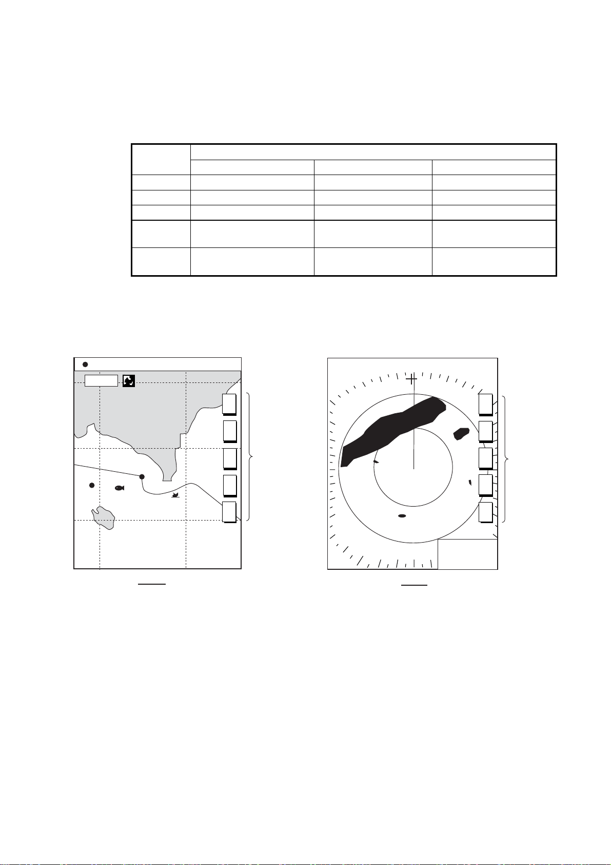
2.1 Plotter Displays
You may show the plotter display over the entire screen, in the overlay screen
(GD-1700C/1710C), or in a combination screen.
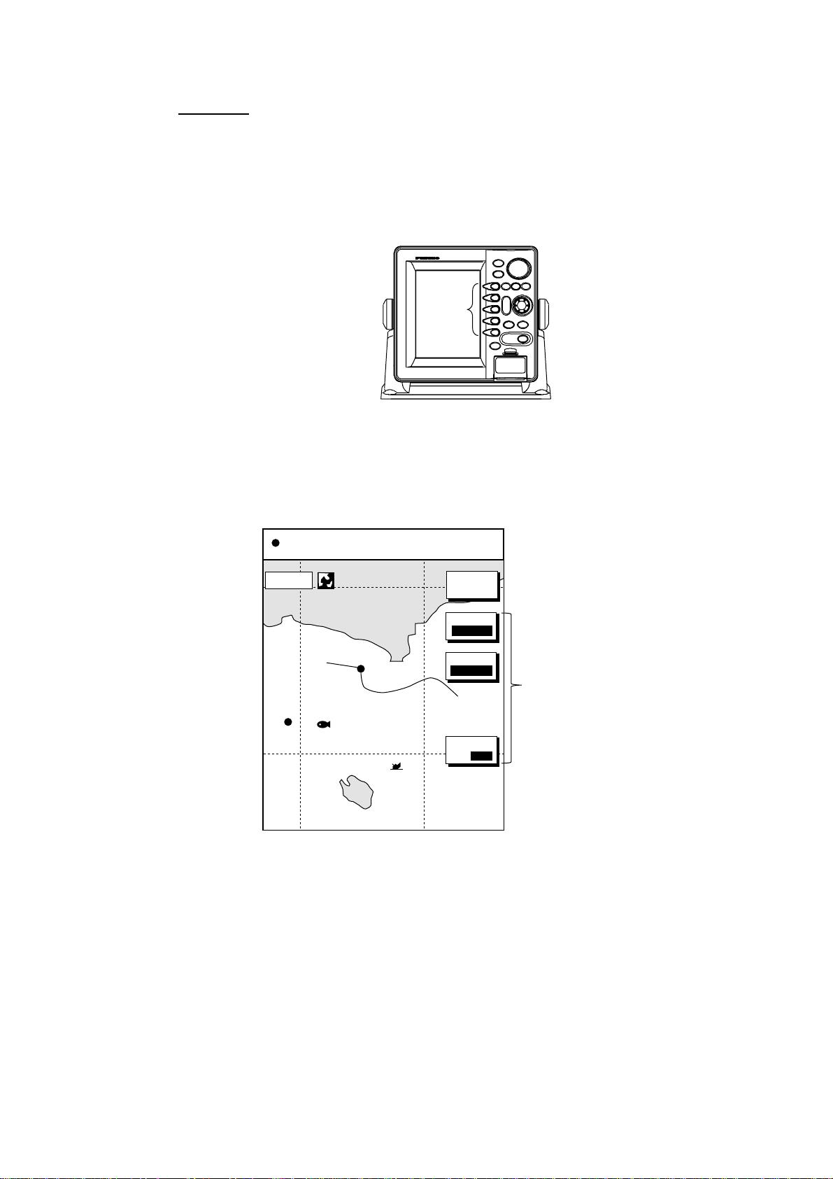
2.1.1 Full-scr e en plotter di s pl a y
Nav data window
(Data changes with NAV soft
key setting and cursor
status. For details see next page.)
Icon (from left)
North Marker
Chart
Alarm
Track Hold
Chart Offset
Save
L/L Offset
Battery
Simulation
(See icon
table on
page A-11
for details.)
Scale
Waypoint name
Waypoint marker
34° 22. 3456'N 359.9° M
080° 22. 3456'E
16.0nm
S
I
M
002WP
FISH
BRIDGE
Course bar
19.9 kt 99.9 nm
TRIP
MARK
ENTRY
MODE
NTH UP
NAV
POS
D. BOX
ON/OFF
Own ship
marker
NU
Own ship
track
Functions for
soft keys
Full-screen plotter display
Note: When GPS signal error is found, the following occurs depending on the
device feeding position data:
GPS Receiver GP-310B/320B: Alarm icon (
) appears and the aural
alarm sounds. Own ship marker blinks faster.
Other navigator: The message “NO GPS FIX” appears and is
accompanied by the aural alarm and alarm icon. If the GPS signal is
missing for more than 90 seconds, the message. “NO POSITION DATA”
appears.
2-1
Page 36

2. PLOTTER OPERATION
Nav data window
The data shown in the nav data window depends on the status of the NAV soft
key and the cursor.
Latitude and longitude
of cursor intersection
Waypoint data
(waypoint selected
with cursor)
Latitude, Longitude
34°24. 3456'N 359. 9°M
+
124°24. 3456'W 59.9nm 99. 9nm
Cursor Mark
001WPT
Bearing to Cursor
TRIP
Range to
Cursor
Trip Distance
CourseBearing to WaypointWaypoint Name
359. 9°M359. 9°M
19. 9nm 19. 9kt 99. 9nm
SpeedRange to WaypointWaypoint Mark Trip Distance
NU
TRIP
Presentation
Mode
Presentation
Mode
NU
Own ship
position
Destination
waypoint
data
Own ship
speed and
course
NAV
POS
soft key
NAV
WPT
soft key
NAV
S/C
soft key
CourseLatitude, Longitude
34°24. 3456'N 359. 9°M
TRIP
NU
124°24. 3456'W 19. 9kt 99. 9nm
Own Ship Mark Speed Trip Distance
Bearing to WaypointWaypoint Name
001WPT
Waypoint Mark
Course, Speed
CSE
359. 9°M 359. 9 °M 79. 9°F NU
SOG
19. 9kt 99. 9nm 345 ft
Range to Waypoint
Bearing to Waypoint
BRG
RNG
359. 9°M TTG4D02H23M NU
19. 9nm
ETA1st 13:45
Estimated Time of
Arrival
TMP
DPT
Presentation
Mode
Time-to-Go
to Destination
Presentation
Mode
Presentation
Mode
2-2
Turns off
nav data
window
NAV
OFF
soft key
Range
to
Waypoint
Water Temp.*,
Depth*
Contents of nav data window
* Requires appropriate
sensor.
Page 37

2.1.2 Compass display
The compass display, shown in combination displays, provides steering
information. The compass rose shows two triangles: the black triangle (hollow on
monochrome model) shows the bearing to destination waypoint and the red
(solid on the monochrome model) triangle, which moves with ship’s course,
shows own ship’s course.
The water temperature and depth graphs, which require appropriate sensors,
show the latest 10 minutes of water temperature and depth data. The range of
the depth graph is 50 feet and it is automatically adjusted with depth.
2. PLOTTER OPERATION
Time-to-go
to destination
Destination
waypoint
bearing
(black on
color model)
Depth
graph*
* = Requires appropriate
sensor.
Destination
waypoint
003WPT
0D 9H 59MTTG 23th23:59
DPT
45.2ft
Shown (in red
on color model)
when direction to
steer is "left."
Speed over ground
Range to destination waypoint
RNG
10.0kt 10.0 kt
SOG
BRG
N
CSE
359.9°M
M
359.9°
0
w
50
Speed through water
99.9
nm
STW
ETA
TMP
16.2°F
20
E
10
Direction to steer
(green on color model)
Estimated time of
arrival at destination
Ship's course
(red on color model)
Water
temperature
graph*
Bearing scale
Own ship marker
(For color model black when within
XTE range, yellow when over. Flashing
on monochrome model when over XTE range.)
XTE monitor
(See next page for
description.)
Compass display
2-3
Page 38

2. PLOTTER OPERATION
Reading t he XTE (cross-track erro r) monitor
The XTE monitor, located below the compass rose, shows the distance you are
off course and the direction to steer to return to course. The own ship marker
moves according to direction and distance off course. It is shown in black when
the amount of cross-track error is within the XTE monitor range and yellow when
it is over. (On the monochrome model it flashes when the amount of cross-track
error is more than the XTE monitor range.) An arrow appears at the right or left
side of the XTE monitor and it shows the direction to steer to return to intended
course. (For the color model the arrow is shown in red when you should steer
left, and green when you should steer right.) In the example on the previous
page you would steer right to return to course. To maintain course, steer the
vessel so the own ship marker stays at the center of the XTE monitor.
Soft keys
EDIT XT-L MT: Sets the range for XTE monitor scale. See the procedure below
for how to set.
RESET XTE: Enables you to restart navigation, when a destination is set. Press
the EDIT XT-LMT soft key followed by the RESET XTE soft key. The following
message is displayed.
RESTART NAVGATION TO
CURRENT WAYPOINT.
ARE YOU SURE?
YES ... PUSH ENTER KNOB
NO ... PUSH CLEAR KEY
Setting the range for the XTE monitor
1. With the compass (or highway) display shown, press the EDIT XT-LMT soft
key to display the following window.
XTE LIMIT
0 .1nm
XTE range setting window
2. Use the cursor pad to select digit to change. Note that all digits may be
cleared by pressing the [CLEAR] key.
3. Rotate the [ENTER] knob to set value, then push it to register setting, or
press the CANCEL soft key to cancel.
2-4
Page 39
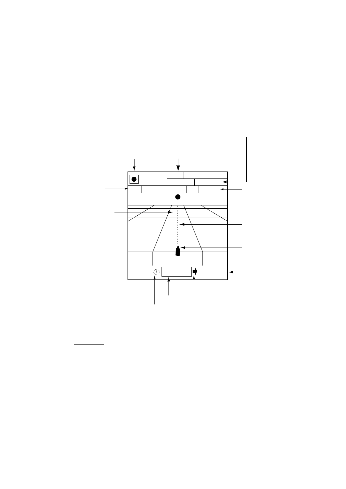
2.1.3 Highway display
The highway display, shown in combination displays, provides a graphic
presentation of ship’s track along intended course. It is useful for monitoring
ship’s progress toward a waypoint. The own ship marker shows relation between
ship and intended course. The XTE monitor shows the direction and amount
your vessel is off course – the arrow shows the direction to steer to return to
your course and the numeric the distance you are off course. Using the figure
below as an example, you would steer right 0.009 nm to return to course. To
maintain course, steer the vessel so the own ship marker stays aligned with the
intended course line.
Speed over ground, speed through water
2. PLOTTER OPERATION
Time-to-go
to destination
Destination waypoint
Destination
waypoint
003WPT
0D 9H 59M
TTG 23th23:59
0.9 nm
Shown (in red on color model) when
direction to steer is "left."
Range to
destination waypoint
RNG
99.9 nm
10.0
kt
SOG
WPT001
0.009nm
XTE monitor
STW
ETA
Direction to steer (green on color model)
10.0
0.9 nm
kt
Estimated time of
arrival at destination
Intended
course
Own ship marker
XTE range
Highway display
Soft keys
EDIT XT-L MT: Sets the range for XTE monitor scale. See the procedure on the
previous page for how to set.
RESET XTE: Enables you to restart navigation, when a destination is set. Press
the EDIT XT-LMT soft key followed by the RESET XTE soft key. See “Soft keys”
on the previous page for details.
2-5
Page 40

2. PLOTTER OPERATION
2.1.4 Nav data display
The nav data display provides comprehensive navigation data, and it can be
shown in a two-screen combination display. The user may select what data to
display and where to display it. For details see the paragraph “5.7 Nav Data
Display Setup.”
Appropriate sensors are required. Bars ( - -) appear when corresponding sensor
is not connected.
Position
POSITION
34° 34. 5678' N
120° 34. 5678'
34° 14. 5678' N
120° 14. 5678'
10.0
9.2°
1324.1
Depth
Bearing to
waypoint
Speed through
water
Waypoint
Position
Full-screen display
W
kt
M
ft
Water temperature
W
SOGWPT POSITION
10.0
kt
COURSESTW
101.6°
RANGEBEARING
0.18
TEMPDEPTH
18.2 °
Range to
waypoint
Course
Speed over ground
M
nm
C
103
ET A
nm
1st 1:25
2001
FEB 1
Half-screen display
TTGTRIP LOG
0D 2H 30
TIMEDATE
01:27:05
M
2-6
Nav data di s plays
Page 41
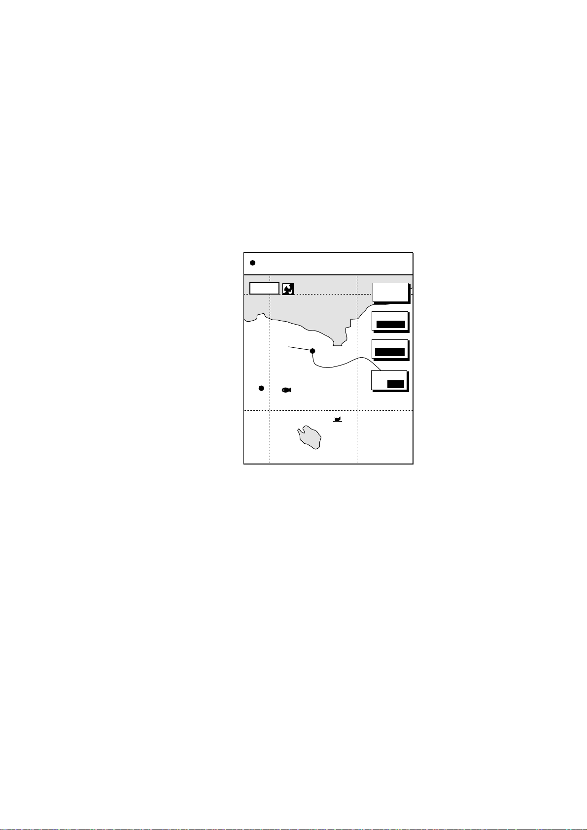
2.2 Presentation Mode
Three types of presentation modes are provided for the plotter display: north-up,
course-up and auto course-up. To change the presentation mode, first press the
[HIDE/SHOW] key if the plotter soft keys are not displayed. Press the MODE soft
key to select desired mode. Each press of the key changes the presentation
mode and presentation mode indication (top right-hand corner of the screen)
cyclically in the sequence of North-up, Course-up and Auto course-up.
2.2.1 North-up
North is at the top of the display and own ship is shown with a filled circle. This
mode is useful for long-range navigation.
34° 22. 3456'N 359.9°M
080° 22. 3456'E
19.9 kt 99.9 nm
TRIP
2. PLOTTER OPERATION
NU
16.0nm
WP-002
FISH
BRIDGE
MARK
ENTRY
MODE
NTH UP
NAV
POS
D.BOX
ON/ OFF
Plotter di s play, north-up mode
2-7
Page 42

2. PLOTTER OPERATION
2.2.2 Course-up
The course-up mode is useful for monitoring ship’s progress towards a waypoint.
The destination is at the top of the screen when a destination is set. When no
destination is set, the course or heading is at the top of the screen at the
moment the course-up mode is selected. A filled triangle marks own ship’s
position. The data sentences GGA and VTG must be output from the NavNet
display unit connected to the GPS navigator in order to correctly orient the own
ship marker in the course-up mode on other NavNet display units.
Plotter di s play, course-up mode, destination set
2.2.3 Auto course-up
The course is at the top of screen at the moment the auto course-up mode is
selected. In this mode, the current course is kept at the top of the screen within
22.5 degrees. For example, if your vessel turns more than 22.5 degrees to port
or starboard, the chart display will rotate so that your course is pointing towards
the top of the screen again.
34° 22. 3456'N 359.9° M
+
080° 22. 3456'E
16.0nm
WPT 001
19.9 kt 99.9 nm
TRIP
MARK
ENTRY
MODE
CSE UP
CENTER
GO TO
CURSOR
D. BOX
ON/ OFF
CU
2-8
34° 22. 3456'N 359.9° M
+
080° 22. 3456'E
16.0 nm
19.9 kt 99.9 nm
TRIP
CU
MARK
ENTRY
MODE
AT CU
CENTER
GOTO
CURSOR
D. BOX
ON/OFF
Plotter di s play , auto course-up mode
Page 43

2.3 Shifting the Display
The plotter display can be shifted as below.
1. Press the cursor pad to display the cursor.
2. Locate the cursor at a screen edge and press and hold down the cursor pad.
The screen shifts in the direction opposite of cursor location.
3. To turn off the cursor, press the CENTER soft key. This also returns the own
ship marker to the screen center.
2.4 Chart Scale
Chart scale (range) may be selected with the [RANGE -] or [RANGE +] key. The
[-] key expands the chart range; the [+] key shrinks it.
2. PLOTTER OPERATION
Charts scales
nm 0.125 0.25 0.5 1 2 4 8 16 32 64 128 256 512 1024 2048
km 0.23 0.46 0.93 1.85 3.70 7.41 14.8 29.6 59.3 119 237 474 948 1896 3792
sm 0.144 0.29 0.58 1.15 2.30 4.60 9.21 18.4 36.8 73.7 147 295 589 1178 2356
Note: When the display is expanded or shrunk beyond the range of the chart
card in use the message “NO CHART” appears, along with the appropriate
chart icon. See the illustration on the next page for details.
2-9
Page 44

2. PLOTTER OPERATION
2.5 Chart Cards
2.5.1 Char t card overvie w
Your unit reads FURUNO and NavCharts™ (NAVIONICS) charts, or C-MAP
charts, depending on the type of display unit you have.
When you insert a suitable chart card in the slot and your boat is near any
cartographic object, a chart appears. If a wrong card is inserted or a wrong chart
scale is selected, landmasses will appear hollow. Chart icons appear at the top
of the display to help you select a suitable chart scale. The table below shows
the chart icons and their meanings.
Chart icons and their meanings
Icon Meaning
Proper card is not inserted or
chart scale is too small.
Operate the RANGE key to
adjust chart scale.
Chart scale is too large.
Operate the RANGE key to
adjust chart scale.
Suitable chart scale is
selected.
2-10
Page 45

2.5.2 Ind ic es an d ch ar t enl ar gement
When the [RANGE] key is operated, you will see several frames appear on the
chart. These frames are called indices and they show you what parts of the chart
can be enlarged in the current range.
Sample chart ( Japan) showing indices
2. PLOTTER OPERATION
When a chart cannot be displayed
A chart will not be displayed in the following conditions:
• When the chart scale is too large or too small.
• When scrolling the chart outside the indices.
When this happens, select proper chart scale.
Note: Indices can be turned on or off. For further details, see page 5-9 for
FURUNO and NAVIONICS charts and page 5-12 for C-MAP charts.
2-1 1
Page 46

2. PLOTTER OPERATION
2.5.3 FURUNO and NavCharts
Chart symbols
™ charts
The table below shows FURUNO and NavCharts
™ chart symbols and their
meanings.
Chart sym bols
Symbol Description
Summit
Wreck
Lighthouse
Lighted Buoy
Buoy
Radio Station
Symbol Description
Position of Sounding
Obstruction
Fishing Reef
Platform
Anchorage
Data for aids to navigation
Selected FURUNO and NavCharts
™ charts can show buoy and lighthouse data.
Simply place the cursor on the lighthouse or buoy mark.
Place the cursor on
a lighthouse or buoy mark.
Lighthous e mark
Example of data displayed
Range and bearing
from own ship
Period (ex.: 6 seconds)
Visibility in nautical
mile (ex.: 12 miles)
NAVAID: /FL 6S 12M
FROM OS 52.38nm 48.0°
FL : Flashing
F : Fixed light
F FL : Fixed and Flashing light
MO : Morse code light
Oc : Occulting light
Exam ple of buoy, lighthouse data
2-12
Page 47

2. PLOTTER OPERATION
Port servic e icons (Nav Charts™ only)
Selected NavCharts show services available at ports, with icons.
1. Use the cursor pad to place the cursor on the sailboat icon (denotes a port or
harbor) desired.
2. Push the [ENTER] knob.
3. Use ◄ or ► to select icon desired at the top of the display. The services
available appear directly below the icon selected.
4. Press the RETURN soft key to finish.
Detailed information of service
selected
List of services
at the port selected
34° 22. 3456'N 359.9°M
+
080° 22. 3456'E
FIRST AID
16.0nm
19.9 kt 99.9 nm
TRIP
NU
Emergency
medical service
Fueling station
CANCEL
Sailboat icon (Port)
Plotter di s play , s howing port ser v ice display
Current (or tide) data
Some NavCharts provide for calculation of
the current (or tide) data for any date.
Additionally it displays the time of sunrise
and sunset, moon shape (on current data.)
1. Use the trackball to place the cursor on
a current icon (
).
2. Press the [ENTER] knob to show the
current window.
3. Press the DATE soft key, and then enter
the date desired.
4. Press the ENTER soft key.
Current data display
Water
supply station
Customer
service station
Port
34 24. 3456 N 359.9 NU
0.86
+
124 24. 3456 W 59.9kt 024nm
0.74
0.61
0.48
0.35
Time: 04:35
Speed (KT): 0.45ft
Angle ( ): 142
21/08/02 +00
Max. Time Speed Aug. Slack
Flood 4:58 1.2 323 7:58
Ebb 23:15 1.2 323 20:15
Flood 17:15 1.1 145 15:15
Ebb 23:15 1.2 323 20:15
Moonphase:
FULLY IN 1 DAY
Moonrise: 14:06
Moonset: 02:15
Sunrise: 05:03
Sunset: 19:10
Traveler's
service station
Marine
equipment service
Information center
0481216 20 24
KT AT
Current
DATE
RETURN
2-13
Page 48

2. PLOTTER OPERATION
2.5.4 C-MAP charts
Cursor and data display
Besides its fundamental functions of providing position data, the cursor can also
show information about caution area, depth area, source of data, etc. on C-MAP
charts. In addition, you can display information about an icon by placing the
cursor on it.
1. Press the cursor pad to turn the cursor on.
2. Use the cursor pad to place the cursor on the position desired.
3. Push the [ENTER] knob to open the Objects window.
Objects
Spot Sounding
Depth area
Exclusive economic zone
Military practice area
Restricted area
Source of data
Objects window
4. Use the cursor pad to select the item desired.
5. Push the [ENTER] knob to display details for object selected.
Depth area
Depth range value1
0.00 Meters
Depth range value2
1829.00 Meters
Exam ple of caution area window
6. Press the RETURN soft key to close the window.
7. Press the [MENU] key to close the menu.
2-14
Page 49

2. PLOTTER OPERATION
Icon data
You may place the cursor on any icon to find information about the selected icon.
1. For example, place the cursor on a lighthouse icon.
Place the cursor on a lighthouse icon.
34° 22. 3456'N 359.9°M
+
080° 22. 3456'E
16.0nm
19.9 kt 99.9 nm
TRIP
NU
MARK
ENTRY
MODE
NTH UP
CENTER
GO TO
CURSOR
D. BOX
ON /OFF
Lighthous e icon
2. Push the [ENTER] knob to show data. For example, the following window
appears for a lighthouse.
Objects
Lighthouse
Tower
Light
Underwater Rock
Depth contour
Depth contour
Depth area
Source of data
Object windows
3. Use the cursor pad to select the item desired.
4. Push the [ENTER] knob to display detailed information.
2-15
Page 50

2. PLOTTER OPERATION
5. Press the RETURN soft key twice to close the Objects window.
Tide information
The C-MAP chart card provides for calculation of the tide heights for any date.
Additionally it displays the times of sunrise and sunset.
1. Press the cursor pad to place the cursor on a Tide icon (T).
2. Push the [ENTER] knob to open the Objects window.
Navigation mark, fixed
Light.
Color
white
Height
7. 00 Meters
Light characteristic
occulting
XXXXXXXX
XXXXXXXX
Sample lighthouse data
34 24. 3456 N 359.9 NU
+
OBJECTS
124 24. 3456 W 59.9kt 024nm
Tide height
Cartographic area
Source of data
T
RETURN
Objects window
3. Use the cursor pad to select “Tide height.”
4. Push the [ENTER] knob to open the TIDE window.
2-16
Page 51

Horizontal
Cursor
Vertical
Cursor
2. PLOTTER OPERATION
34 24. 3456 N 359.9 NU
+
0.86
124 24. 3456 W 59.9kt 024nm
0.74
0.61
0.48
0.35
04812162024
Time: 04:35
Height: 0.45ft
Draught: 0.65ft
01/07/30 +13:30
43° 32.860N
010° 18.022E
DATE
Port info
LIVORNO (LEGHORN)
High Water(max)
Low Water(min)
Sunrise
07:52L
0.86ft(13:30 L)
0.35ft(21:00 L)
Sunset
16:53 L
RETURN
Tide window
5. Press the DATE soft key to open the DATE window.
CHANGE DATE
(DAY. MONTH. YEAR)
01. 01. 2001
LIMIT: 31.12.2099
Date window
6. Use ◄ or ► to position the cursor where desired, then rotate the [ENTER]
knob to set character. Repeat to enter complete date.
7. Push the [ENTER] knob to show the tidal graph for entered date.
8. Use ◄ or ► to locate the vertical cursor on the hour desired.
9. Use ▲ or ▼ to shift the level cursor to select draught.
10. See the time, height and draught indications below the tide graph for tide
information.
11. Press the RETURN soft key to close the TIDE window.
Port servic e icons
Objects
Selected C-MAP shows services available at ports,
with lists.
1. Use the cursor pad to place the cursor on the
sailboat icon (denotes a port or harbor) desired.
2. Push the [ENTER] knob.
3. Select the service name desired. The services
Port area
Port/Marine
Fuel station
Water
Electricity
Showers
Pubric toilets
Pubric telephone
available appear.
4. Press the CANCEL soft key.
C-map, port service display
2-17
Page 52

2. PLOTTER OPERATION
2.6 Working with Track
Your ship’s track is plotted on the screen using navigation data fed from
position-fixing equipment. This section shows you what you can do with track,
from turning it on or off to changing its plotting interval. Own ship’s track is
displayed in the default setting and on the color model it is red.
2.6.1 Displaying track
Own ship track
1. Press the [MENU] key followed by the CHART SETUP and TRACKS &
MARKS CONTROL soft keys to open the TRACK CONTROL menu.
OWN SHIP TRACK DISP
ON
OWN SHIP TRACK COLOR
RED
TARGET TRACK DISPLAY
ON
TARGET TRACK COLOR
WHITE
INTERVAL
TIME
TIME INTERVAL
10m00s
DISTANCE INTERVAL
00.10nm
MEMORY(TRACK & MARK)
2000PTS
(MARK MEMORY)
(6000)POINTS
TRACK
CONTROL
EDIT
TRACK
RESUME
ERASE
T & M
MARK
SETUP
(MARK MEMORY)
(6000)POINTS
RETURN
OWN SHIP TRACK DISP
ON
TARGET TRACK DISPLAY
ON
INTERVAL
TIME
TIME INTERVAL
10m00s
DISTANCE INTERVAL
00.10nm
MEMORY(TRACK & MARK)
2000PTS
TRACK
CONTROL
EDIT
TRACK
RESUME
ERASE
T & M
MARK
SETUP
RETURN
SHIP’S TRACK STATUS
TRACKING
TRACK: 1234/2000
MARK : 9/6000
SHIP’S TRACK STATUS
TRACKING
TRACK: 1234/2000
MARK : 9/6000
GD-1700GD-1700C/1710C
Track contr ol menu
2. Use the cursor pad to select OWN SHIP TRACK DISP.
3. Press the EDIT soft key to show the track display window.
4. Use the cursor pad to select ON (default setting) or OFF as appropriate.
5. Press the ENTER soft key.
6. Press the [MENU] key to close the menu.
Note: The number of track and mark points used appears at the SHIP’S TRACK
STATUS window on the TRACK CONTROL menu. Using the figure above
as an example, 1234 points of track and 9 marks have been recorded.
2-18
Page 53
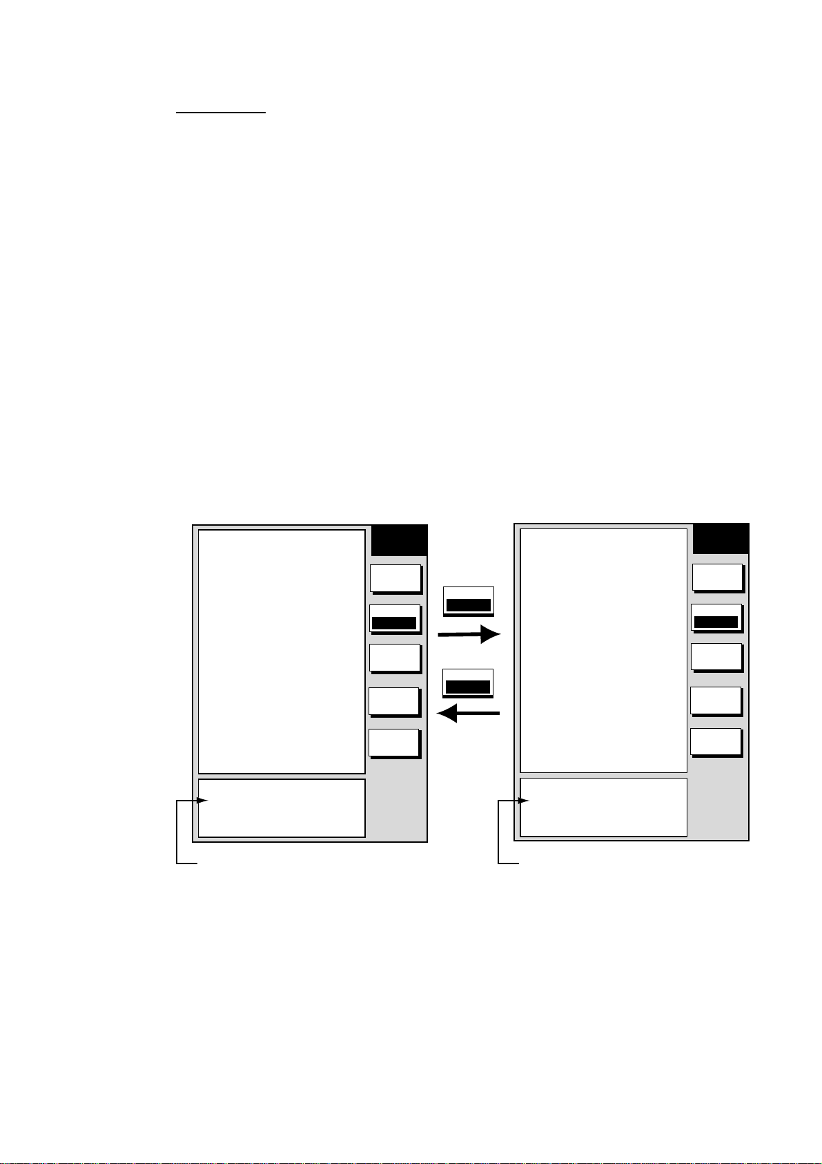
2. PLOTTER OPERATION
Target tr ack
Target track, NMEA format TTM (Tracked Target Message) data sentence, may
be turned on or off as desired. The default setting is ON.
1. Press the [MENU] key followed by the CHART SETUP and TRACKS &
MARKS CONTROL soft keys to open the TRACK CONTROL menu.
2. Use the cursor pad to select TARGET TRACK DISPLAY.
3. Press the EDIT soft key to show the target track display window.
4. Use the cursor pad to select to ON or OFF as appropriate.
5. Press the ENTER soft key.
6. Press the [MENU] key to close the menu.
2.6.2 Stopping, restarting plotting of own ship track
When your boat is at anchor or returning to port you probably won’t need to
record its track. You can stop recording the track, to conserve the track memory,
as follows:
1. Press the [MENU] key followed by the CHART SETUP and TRACKS &
MARKS CONTROL soft keys to open the TRACK CONTROL menu.
▲
OWN SHIP TRACK DISP
OWN SHIP TRACK COLOR
TARGET TRACK DISPLAY
TARGET TRACK COLOR
INTERVAL
TIME INTERVAL
DISTANCE INTERVAL
MEMORY(TRACK & MARK)
(MARK MEMORY)
(6000)POINTS
SHIP’S TRACK STATUS
TRACKING
TRACK: 1234/2000
MARK : 9/6000
ON
RED
ON
WHITE
TIME
00m10s
00.10nm
2000PTS
Track is plotted
TRACK
CONTROL
EDIT
TRACK
RESUME
ERASE
T & M
MARK
SETUP
RETURN
TRACK
RESUME
TRACK
HALT
▲
OWN SHIP TRACK DISP
OWN SHIP TRACK COLOR
TARGET TRACK DISPLAY
TARGET TRACK COLOR
INTERVAL
TIME INTERVAL
DISTANCE INTERVAL
MEMORY(TRACK & MARK)
(MARK MEMORY)
(6000)POINTS
SHIP’S TRACK STATUS
NOT TRACKING
TRACK: 1234/2000
MARK : 9/6000
ON
RED
ON
WHITE
TIME
00m10s
00.10nm
2000PTS
Track not plotted
Track control menu (GD-17 00C/1710C)
2. Press the TRACK RESUME soft key. The soft key now shows “TRACK
HALT” and the indication “TRACKING” in the SHIP’S TRACK STATUS
window changes to “NOT TRACKING.” In addition, the icon “H” is displayed
at the top of the plotter display and own ship marker becomes a hollow circle.
To restart plotting the track, press the TRACK HALT soft key.
3. Press the [MENU] key to close the menu.
TRACK
CONTROL
EDIT
TRACK
HALT
ERASE
T & M
MARK
SETUP
RETURN
2-19
Page 54

2. PLOTTER OPERATION
2.6 .3 Changing track color (GD-1700C/1710C )
Track can be displayed in red (default setting), yellow, green, light-blue, purple,
blue and white. It can be useful to change track color on a regular basis to
discriminate between previous day’s track, etc.
Own ship’s track
1. Press the [MENU] key followed by the CHART SETUP and TRACKS &
MARKS CONTROL soft keys to open the TRACK CONTROL menu.
2. Use the cursor pad to select OWN SHIP TRACK COLOR.
3. Press the EDIT soft key to display the track color window.
TRACK COLOR
▲
¤
RED
¡
YELLOW
¡
GREEN
¡
LIGHT BLUE
¡
PURPLE
¡
BLUE
¡
WHITE
▼
Own shi p track color w indow
4. Use the cursor pad to select the color desired.
5. Press the ENTER soft key.
6. Press the [MENU] key to close the menu.
Target tr ack
Like own ship’s track, target tracks can be displayed in red, yellow, green,
light-blue, purple, blue and white (default setting).
1. Press the [MENU] key followed by the CHART SETUP and TRACKS &
MARKS CONTROL soft keys to open the TRACK CONTROL menu.
2. Use the cursor pad to select TARGET TRACK COLOR.
3. Press the EDIT soft key to display the track color window.
4. Use the cursor pad to select the color desired.
5. Press the ENTER soft key.
6. Press the [MENU] key to close the menu.
2-20
Page 55
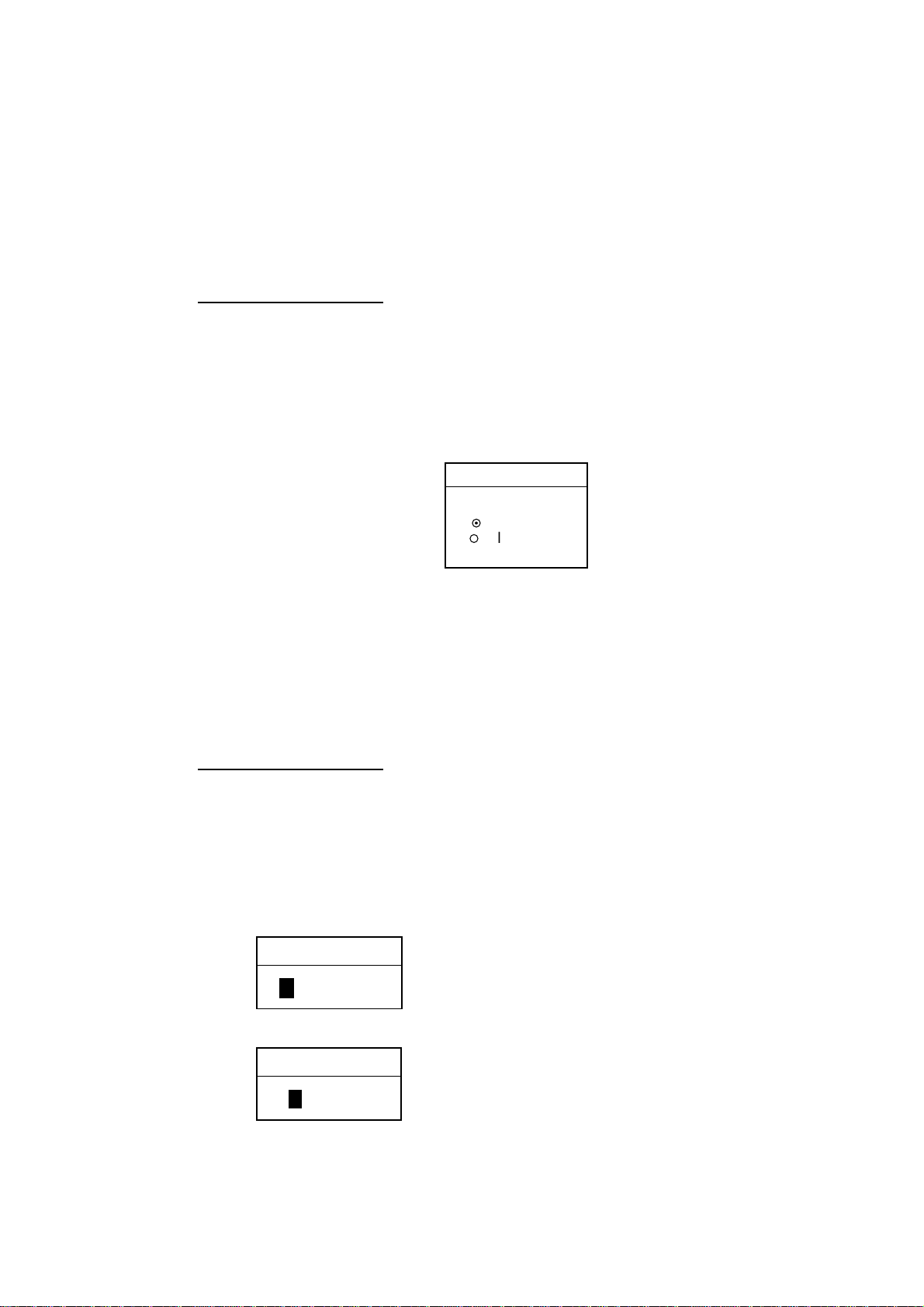
2. PLOTTER OPERATION
2.6.4 Track plotting method and interval for own ship track
In drawing the own ship track, first the ship’s position fed from position-fixing
equipment is stored into the unit’s memory at an interval of time or distance. A
shorter interval provides for better reconstruction of the track, but the storage
time of the track is reduced. When the track memory becomes full, the oldest
track is erased to make room for the latest.
Track plotting method
Track may be plotted by time or distance. The default setting is “time.”
1. Press the [MENU] key followed by the CHART SETUP and TRACKS &
MARKS CONTROL soft keys to open the TRACK CONTROL menu.
2. Use the cursor pad to select INTERVAL.
3. Press the EDIT soft key to display the plot window.
INTERVAL
▲
¤
TIME
¡
DISTANCE
▼
Plot wi ndow
4. Use the cursor pad to select TIME or DISTANCE as appropriate. Distance is
useful for conserving track memory, since no track is recorded when the boat
is stationary.
5. Press the ENTER soft key.
6. Press the [MENU] key to close the menu.
Track plot t ing interval
1. Press the [MENU] key followed by the CHART SETUP and TRACKS &
MARKS CONTROL soft keys to open the TRACK CONTROL menu.
2. Use the cursor pad to select TIME INTERVAL or DISTANCE INTERVAL as
appropriate.
3. Press the EDIT soft key to display the time or distance interval window,
depending on what you selected at step 2.
TIME INTERVAL
Setting range: 0 min 1 sec (continuous) - 99 min 59 sec
Default setting: 10 sec
00m10s
(When selecting TIME INTERVAL.)
DISTANCE INTERVAL
Setting range: 0.01 nm (continuous) - 99.99 nm (km, sm)
Default setting: 0.1 nm
00.10nm
(When selecting DISTANCE INTERVAL.)
Interval w indows
2-21
Page 56

2. PLOTTER OPERATION
4. Use the [ENTER] knob and the cursor pad to enter numeric data. The
[CLEAR] key functions to clear an entire line of data.
5. Push the [ENTER] knob or ENTER soft key.
6. Press the [MENU] key to close the menu.
2.6.5 Changing own ship track/mark distri bu ti on se tting
The equipment stores a total of 8000 points of track and marks. This amount
may be distributed as desired, and the default setting is 2000 points of track and
6000 marks.
When you change the track memory setting, all tracks and marks in the memory
are erased. If necessary save the data to a memory card. For further details, see
the paragraph “6.1.2 Saving data to a memory card”.
1. Press the [MENU] key followed by the CHART SETUP and TRACKS &
MARKS CONTROL soft keys to open the TRACK CONTROL menu.
2. Use the cursor pad to select MEMORY (TRACK & MARK).
3. Press the EDIT soft key to display the track memory window.
TRACK MEMORY
2000/8000 POINTS
Track memory window
4. Use the cursor pad and [ENTER] knob to enter desired number of track
memory points.
5. Push the [ENTER] knob or ENTER soft key. You are asked if you are sure to
change the track memory capacity.
6. Push the [ENTER] knob.
7. Press the [MENU] key to close the menu.
2-22
Page 57

2.6.6 Erasing track
This paragraph shows you how to erase own ship’s track and target tracks. You
can erase ship’s track three ways: collectively, by color (color model only) and by
area.
Erasing o wn shi p track by area
You can erase own ship’s track by area as below. This feature is not available
when the overlay mode (GD-1700C/1710C only) is in use.
1. Press the [MENU] key followed by the CHART SETUP, TRACKS & MARKS
CONTROL and ERASE T & M soft keys to show the ERASE menu.
2. PLOTTER OPERATION
ERASE ALL TRACKS
ERASE TRACKS BY AREA
ERASE TRACKS BY COLOR
ERASE TARGET TRACKS
ERASE ALL MARKS/LINES
ERASE MARKS BY AREA
SHIP’S TRACK STATUS
TRACKING
TRACK: 1234/2000
MARK : 9/6000
ERASE
EDIT EDIT
ERASE ALL TRACKS
ERASE TRACKS BY AREA
ERASE TARGET TRACKS
ERASE ALL MARKS/LINES
ERASE MARKS BY AREA
SHIP’S TRACK STATUS
TRACKING
TRACK: 1234/2000
MARK : 9/6000
GD-1700GD-1700C/1710C
ERASE
RETURNRETURN
Erase menu
2. Use the cursor pad to select ERASE TRACKS BY AREA, then press the
EDIT soft key. The menu is erased and the plotter display appears.
3. Use the cursor pad to place the cursor at the top left of corner which you
want to erase track from.
4. Press the START soft key or the [ENTER] knob.
5. Move the cursor diagonally to the bottom right corner of the area which you
want to erase track from.
6. Press the END soft key or the [ENTER] knob. You are asked if you are sure
to delete the track.
7. Push the [ENTER] knob to delete the track selected.
8. Press the [MENU] key twice to close the menu.
2-23
Page 58
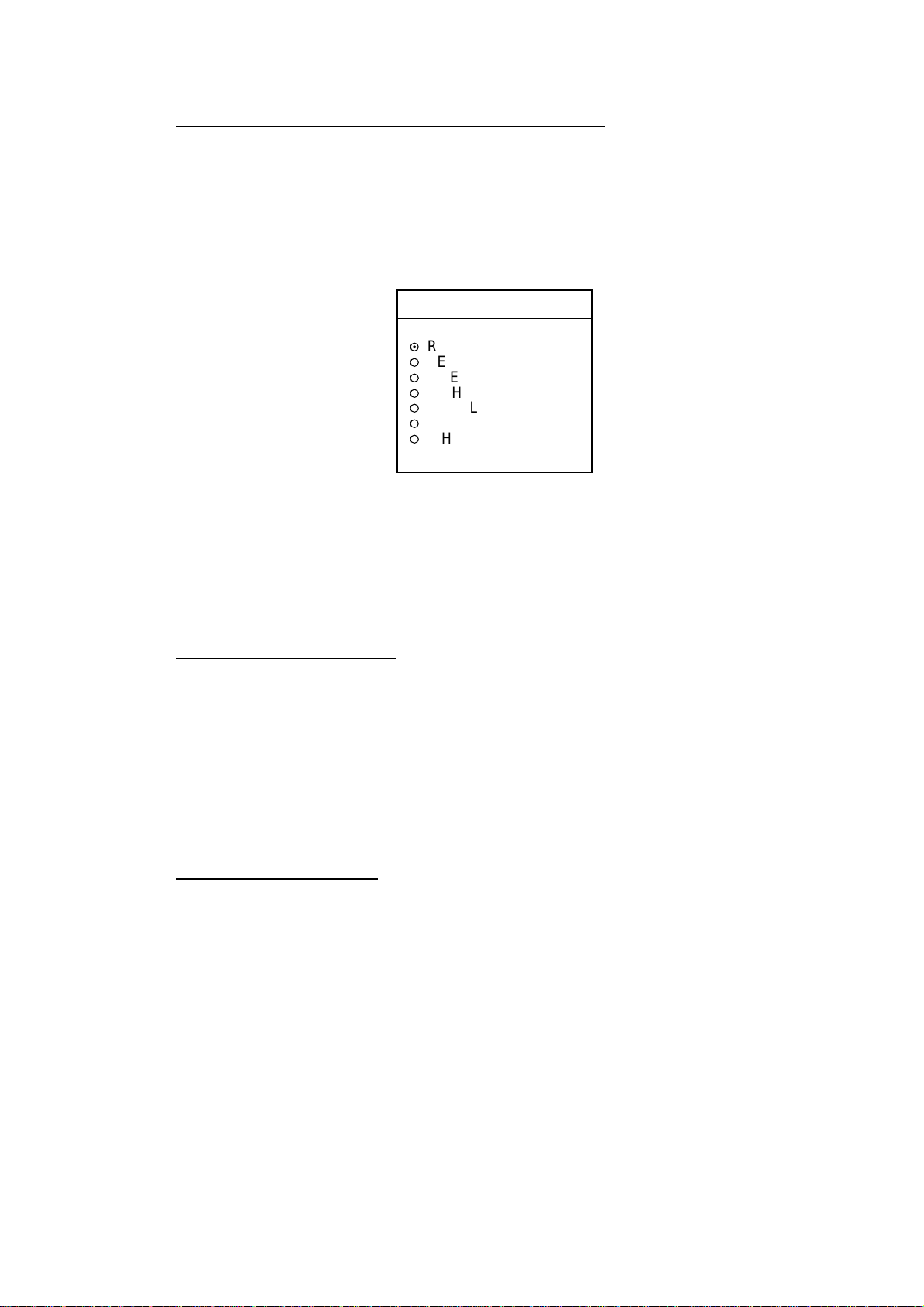
2. PLOTTER OPERATION
Erasing o wn shi p track by co lor (GD-1700C/1710C)
You may erase own ship’s track by color as follows:
1. Press the [MENU] key followed by the CHART SETUP, TRACKS & MARKS
CONTROL and ERASE T & M soft keys to show the ERASE menu.
2. Use the cursor pad to select ERASE TRACKS BY COLOR, then press the
EDIT soft key.
ERASE TRK BY COLOR
▲
¤
RED
¡
YELLOW
¡
GREEN
¡
LIGHT BLUE
¡
PURPLE
¡
BLUE
¡
WHITE
▼
Erase track by c olor wi ndow
3. Use the cursor pad to select the color you want to erase, then push the
[ENTER] knob.
4. Push the [ENTER] knob to erase the track color selected.
5. Press the [MENU] key twice to close the menu.
Erasing al l own ship track
1. Press the [MENU] key followed by the CHART SETUP, TRACKS & MARKS
CONTROL and ERASE T & M soft keys to show the ERASE menu.
2. Use the cursor pad to select ERASE ALL TRACKS, then press the EDIT soft
key.
3. Push the [ENTER] knob to erase all own ship track.
4. Press the RETURN soft key.
5. Press the [MENU] key twice to close the menu.
Erasing al l target t racks
1. Press the [MENU] key followed by the CHART SETUP, TRACKS & MARKS
CONTROL and ERASE T & M soft keys to show the ERASE menu.
2. Use the cursor pad to select ERASE TARGET TRACKS, then press the EDIT
soft key.
3. Push the [ENTER] knob to erase all target tracks.
4. Press the [MENU] key twice to close the menu.
2-24
Page 59
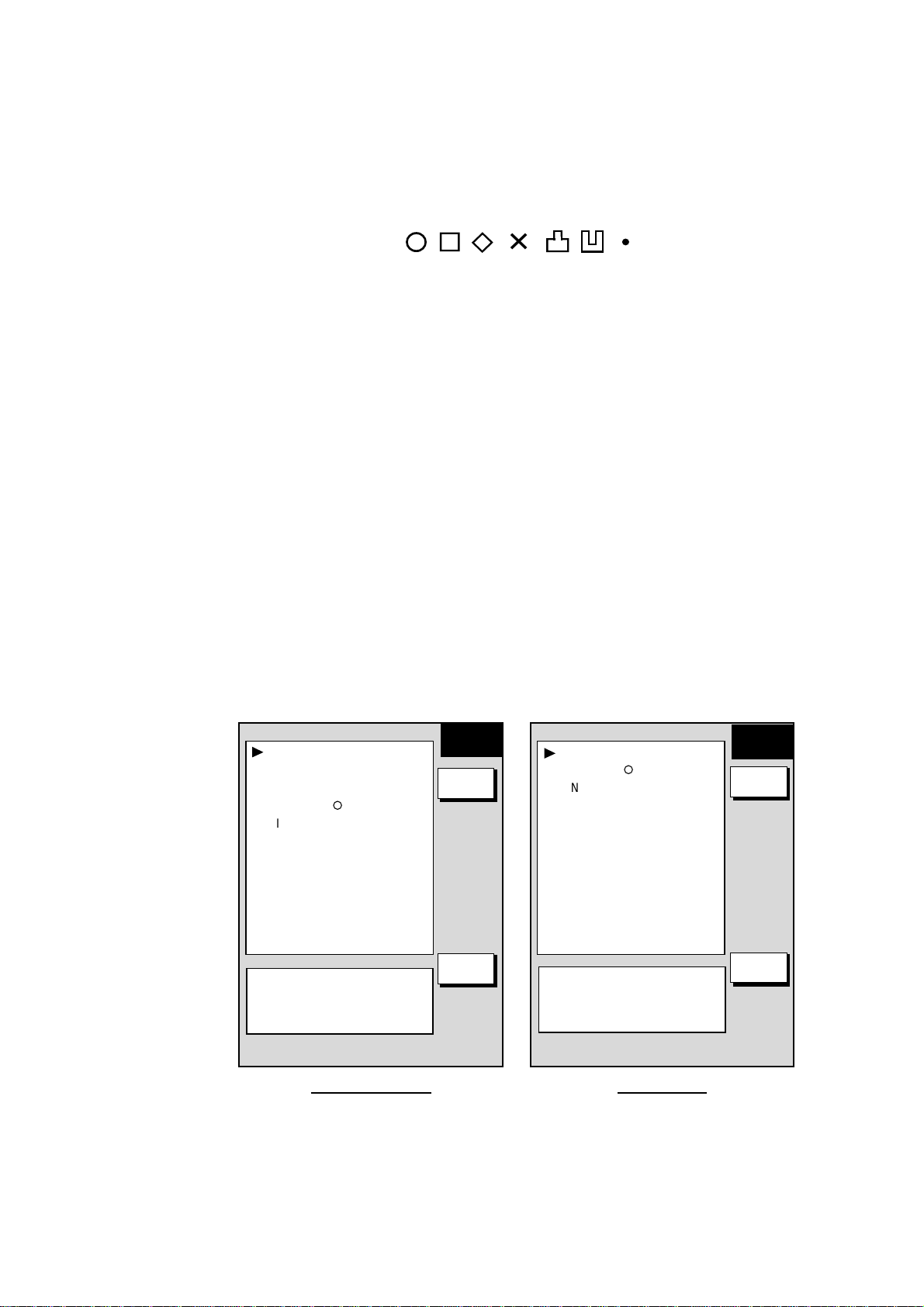
2.7 Marks, Lines
Marks are useful for denoting important points such as a good fishing spot.
Marks can be inscribed in seven shapes and seven colors (GD-1700C/1710C):
Red, yellow, green, light-blue, purple, blue and white.
2. PLOTTER OPERATION
¡
2.7.1 Entering a mark, line
1. Place the cursor where you want a mark to appear.
2. Press the MARK ENTRY soft key. (Press the [HIDE/SHOW] key if the plotter
soft keys are not shown.)
The mark is inscribed in the size and shape selected on the mark & line menu.
The default mark attributes are size, large; color (GD-1700C/1710C), yellow, and
shape, hollow circle (
2.7.2 Changing mark attributes
You can select the size, shape and color (color model) for marks on the MARKS
& LINES menu.
1. Press the [MENU] key to show the menu.
2. Press the CHART SETUP, TRACKS & MARKS CONTROL and MARK
SETUP soft keys to show the MARKS & LINES menu.
○).
✕
Mark shapes
MARKS/LINES COLOR
YELLOW
MARKS SHAPE
¡
LINES STYLE
.
MARKS SIZE
LARGE
SHIP’S TRACK STATUS
TRACKING
TRACK: 1234/2000
MARK : 9/6000
GD-1700C/1710C GD-1700
MARKS &
LINES
EDIT
RETURN
MARKS SHAPE
¡
LINES STYLE
.
MARKS SIZE
LARGE
SHIP’S TRACK STATUS
TRACKING
TRACK: 1234/2000
MARK : 9/6000
MARKS &
LINES
EDIT
RETURN
Mark & line menu
3. For the GD-1700C/1710C, do the following to select mark and line color.
a) Select MARKS/LINES COLOR, then press the EDIT soft key.
b) Use the cursor pad to choose color desired. Press the ENTER soft key.
2-25
Page 60

2. PLOTTER OPERATION
4. Select MARKS SHAPE, then press the EDIT soft key.
5. Use the cursor pad to select mark shape desired, then press the RETURN
soft key.
6. Select MARKS SIZE, then press the EDIT soft key.
7. Use the cursor pad to select LARGE (default setting) or SMALL as
appropriate.
8. Press [ENTER] knob or ENTER soft key.
9. Press the [MENU] key twice to close the menu.
MARKS SHAPE
▲
¤
¡
¡
¡
✕
¡
¡
¡
¡
▼
Mark shape window
2.7.3 Selecting line type
You may inscribe lines to denote good fishing spots, areas of special interest, etc.
You can even construct simple charts.
1. Press the [MENU] key followed by the CHART SETUP, TRACKS & MARKS
CONTROL and MARK SETUP soft keys to show the MARK & LINES menu.
MARKS/LINES COLOR
YELLOW
MARKS SHAPE
¡
LINES STYLE
.
MARKS SIZE
LARGE
SHIP’S TRACK STATUS
TRACKING
TRACK: 1234/2000
MARK : 9/6000
MARKS &
LINES
EDIT
RETURN
MARKS SHAPE
¡
LINES STYLE
.
MARKS SIZE
LARGE
SHIP’S TRACK STATUS
TRACKING
TRACK: 1234/2000
MARK : 9/6000
MARKS &
LINES
EDIT
RETURN
2-26
GD-1700C/1710C GD-1700
Marks & lines setup menu
2. Select LINE STYLE, then press the EDIT soft key.
Page 61

3. Use the cursor pad to select line style desired. Press the ENTER soft key.
Line style “dot” disables line drawing. The joint between lines is determined
by mark shape. For example, selecting the circle shape will join lines with a
circle as below.
4. Press the [MENU] key twice to close the menu.
2.7.4 Erasing marks, lines
LINES STYLE
▲
¤
¡
----
¡
¡
▼
Mark li ne window
2. PLOTTER OPERATION
Erasing an individual mark
1. Operate the cursor pad to place the cursor on the mark you want to erase.
2. Press the [CLEAR] key to erase the mark.
Erasing an individual line
Place the cursor on an end of the line to erase, then press the [CLEAR] key.
Placing the cursor at the intersecting point of two line segments will erase both
line segments.
Erasing marks, lin es by area
This feature is not available when the overlay mode (GD-1700C/1710C only) is
in use.
1. Press the [MENU] key followed by the CHART SETUP, TRACKS & MARKS
CONTROL and ERASE T & M soft keys to show the ERASE menu.
2. Use the cursor pad to select ERASE MARKS BY AREA and press the EDIT
soft key. The menu is erased and the plotter display appears.
3. Use the cursor pad to place the cursor at the top left-hand corner of the area
which you want to erase marks and lines from.
4. Press the START soft key or the [ENTER] knob.
5. Move the cursor to the bottom right-hand corner of the area which you want
to erase marks and lines from.
6. Press the END soft key or the [ENTER] knob. You are asked if you are sure
to delete the marks/lines selected. Push the [ENTER] knob to delete.
7. Press the [MENU] key twice to close the menu.
2-27
Page 62

2. PLOTTER OPERATION
Erasing al l marks, lin es
You can erase all marks and lines collectively. Be absolutely sure you want to
erase all marks and lines - erased marks and lines cannot be restored.
1. Press the [MENU] key followed by the CHART SETUP, TRACKS & MARKS
CONTROL and ERASE T & M soft keys to show the ERASE menu.
2. Use the cursor pad to select ERASE ALL MARKS/LINES, then press the
EDIT soft key.
3. Push the [ENTER] knob to erase all marks and lines.
4. Press the [MENU] key twice to close the menu.
2-28
Page 63
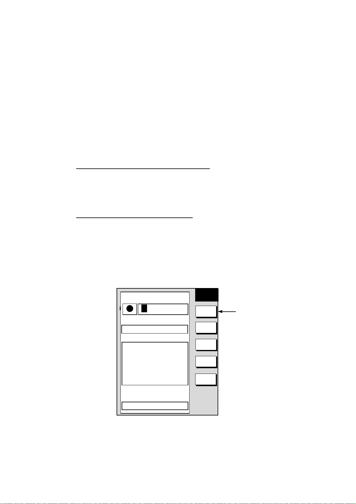
2.8 Waypoints
In navigation terminology, a waypoint is a particular location on a voyage
whether it be a starting, intermediate or destination point. A waypoint is the
simplest piece of information your equipment requires to get you to a destination,
in the shortest distance possible.
This unit has 999 waypoints into which you can enter position information. You
may enter a waypoint five ways: at own ship position, at MOB position (page
1-15), by cursor, by range and bearing, and through the waypoint list (manual
input of latitude and longitude).
2.8.1 Entering waypoints
Entering a waypoint at own ship position
Press the [SAVE/MOB] key momentarily to store your position as a waypoint.
This new waypoint is saved to the waypoint list, under the youngest empty
waypoint number.
Entering a waypoint with the cursor
2. PLOTTER OPERATION
1. Press the [MENU] key to open the menu.
2. Press the WAYPOINTS/ROUTES, WAYPOINTS and WAYPOINT BY
CURSOR soft keys. The plotter display appears.
3. Use the cursor pad to place the cursor where you want to enter a waypoint.
4. Press the NEW WPT soft key. The waypoint window appears and it shows
waypoint mark shape, waypoint name, comment (default: date and time),
position of waypoint and proximity alarm radius.
NEW
MARK
▲
NAME
001WPT
34°44.000'N
135°21.000'W
COMMENT
02:36 01JAN01
LAT
34° 12. 134'N
LON
134° 12. 345'W
PROXIMITY ALARM RADIUS
002WPT
00:00 01JAN00
34°44.000'N
135°21.000'W
003WPT
00:00 01JAN00
34°44.000'N
135°21.000'W
359.9°
0.00nm
359.9°
0.00nm
359.9°
0.00nm
0. 00nm
WPT
SELECT
MARK
COORD
TYPE
N < - -> S
E < - -> W
SAVE
RETURN
"MARK SHAPE"
on monochrome
model
Waypoint window
5. If you do not need to change the waypoint data, press the SAVE soft key
to register the waypoint. The steps which follow show you how to change
waypoint data.
6. For the color model, press the SELECT MARK soft key.
2-29
Page 64

2. PLOTTER OPERATION
7. Press the MARK SHAPE soft key to open the mark shape selection window.
8. Operate the cursor pad to select shape desired.
9. Press the ENTER soft key.
10. For the GD-1700C/1710C, press the SELECT MARK and MARK COLOR
soft keys in that order to open the waypoint mark color selection window.
Select color desired, then press the ENTER soft key.
SELECT MARK
Waypoint mark shape selection window
SELECT COLOR
▲
¤
RED
¡
YELLOW
¡
GREEN
¡
LIGHT BLUE
¡
PURPLE
¡
BLUE
¡
WHITE
▼
Waypoi nt mark color s elec tion window
Note: You cannot change the shape and color of a waypoint when the
proximity alarm radius for it is other than “zero.” To change shape or
color, enter all zeroes as the proximity alarm radius.
12. You can change the name (1 to 6 characters), comment (13 characters), L/L
position and the proximity alarm radius for a waypoint as follows:
a) Use the cursor pad to select the NAME, COMMENT, position box or
PROXIMITY ALARM RADIUS field. (“Proximity alarm radius” provides for
visual and aural alarms when your boat nears a waypoint by the distance
specified. The proximity alarm must be turned on in the ALARM menu to
use this feature. For details see the paragraph “2.11.6 Proximity alarm.”)
2-30
b) Use the cursor pad to select location.
c) Rotate the [ENTER] knob to select appropriate alphanumeric character.
13. Press the SAVE soft key to register the waypoint.
14. Enter another waypoint, or press the [MENU] key to close the menu.
Page 65

2. PLOTTER OPERATION
Entering a waypoint by range and bearing
This method is useful when you want to enter a waypoint using range and
bearing to a target found on a radar.
1. Press the [MENU] key to open the menu.
2. Press the WAYPOINTS/ROUTES, WAYPOINTS and WAYPOINT BY RNG &
BRG soft keys.
3. An “X” (red on the GD-1700C/1710C) appears at own ship position, and it is
the origin point for range and bearing. Operate the cursor pad to place the
cursor on the location desired. Range and bearing from own ship to the
cursor appear at the top of the display.
Note: The origin point of range and bearing can be shifted to the location
desired. Operate the cursor pad to select location, then press the
START POINT soft key.
4. Press the NEW WPT soft key. The waypoint window appears and it shows
mark shape, waypoint name, comment (default: date and time), position of
waypoint and proximity alarm radius.
NEW
MARK
▲
NAME
001WPT
34°44.000'N
135°21.000'W
COMMENT
02:36 01JAN01
LAT
34° 12. 134'N
LON
134° 12. 345'W
PROXIMITY ALARM RADIUS
002WPT
00:00 01JAN00
34°44.000'N
135°21.000'W
003WPT
00:00 01JAN00
34°44.000'N
135°21.000'W
359.9°
0.00nm
359.9°
0.00nm
359.9°
0.00nm
0. 00nm
WPT
SELECT
MARK
COORD
TYPE
N < - -> S
E < - -> W
SAVE
RETURN
"MARK SHAPE"
on monochrome
model
Waypoint window
5. If necessary, change waypoint data following the instructions from step 6 in
“Entering a waypoint with the cursor” on page 2-30.
6. Press the SAVE soft key to register the waypoint.
7. Enter another waypoint as above, or press the [MENU] key to finish.
2-31
Page 66

2. PLOTTER OPERATION
Entering a waypoint from the waypoint list
You can manually enter waypoint position from the waypoint list as follows:
1. Press the [MENU] key to open the menu.
2. Press the WAYPOINTS/ROUTES and WAYPOINTS soft keys.
3. Press the LOCAL LIST (lists waypoints in order from nearest to furthest) or
ALPHANUMERIC LIST (lists waypoints in alphanumeric order) soft key.
ABALONE
▲
▲
00:00 01JAN01
35°47.010'N
135°21.000'W
CRAB
00:00 01JAN01
34°42.000'N
135°21.050'W
FISH
00:00 01JAN01
34°41.000'N
135°21.030'W
LOBSTER
00:00 01JAN01
38°44.300'N
135°21.010'W
PUSH ENTER KNOB TO
SEARCH FOR
350.9
°
3.80 nm
050.9°
1.98 nm
065.9°
1.83 nm
144.9°
4.93nm
---
Alphanumeric waypoint list
Alphanumer ic and local waypoint lists
4. Press the NEW WPT soft key to show the waypoint window (see the figure
on the previous page). Own ship position is shown in the position box.
5. Select the position box and enter position desired.
6. If desired, change waypoint data following the instructions from step 6 in
“Entering a waypoint with the cursor” on page 2-30.
7. Press the SAVE soft key to register the waypoint.
8. Press the [MENU] key to close the menu.
2.8.2 Editing waypoint data
WPT
ALPHA
GOTO
NEW
WPT
EDIT
WPT
ERASE
WPT
RETURN
FISH
▲
00:00 01JAN01
34°41.000'N
135°21.030'W
CRAB
00:00 01JAN01
34°42.000'N
135°21.050'W
ABALONE
00:00 01JAN01
35°47.010'N
135°21.000'W
LOBSTER
00:00 01JAN01
38°44.300'N
135°21.010'W
065.9°
1.83 nm
050.9°
1.98 nm
350.9
°
3.80 nm
144.9°
4.93nm
Local waypoint list
WPT
LOCAL
GOTO
NEW
WPT
EDIT
WPT
ERASE
WPT
RETURN
2-32
Waypoint data may be edited from the waypoint list or directly from the plotter
display.
Editing waypoint data from the waypoint list
1. Press the [MENU] key to open the menu.
2. Press the WAYPOINTS/ROUTES and WAYPOINTS soft keys.
3. Press the LOCAL LIST or ALPHANUMERIC LIST soft key as appropriate.
4. Use the cursor pad to select the waypoint you want to edit.
5. Press the EDIT WPT soft key.
6. Edit data as appropriate.
Page 67

2. PLOTTER OPERATION
7. Press the SAVE soft key.
8. Press the [MENU] key to close the menu.
Editing a waypoint from the plotter display
You may edit waypoints from the plotter display as follows:
1. Press the [MENU] key followed by the WAYPOINTS/ROUTES and
WAYPOINTS soft key to open the waypoint menu.
2. Press the WAYPOINT BY CURSOR soft key.
3. Operate the cursor pad to place the cursor on the waypoint which you want
to change. A flashing diamond mark appears on the waypoint when it is
correctly selected.
4. Press the EDIT/MOVE soft key. Three soft keys replace the EDIT/MOVE soft
key:
EDIT WPT: Edit from the waypoint entry window.
MOVE WPT: Move waypoint to new position with the cursor.
ERASE WPT: Erase waypoint. See paragraph 2.8.3.
5. Press appropriate soft key. For “EDIT WPT,” the waypoint entry window
appears; edit data as appropriate. For “MOVE WPT,” do the following:
a) Operate the cursor pad to place the cursor on the location desired for the
waypoint. A line connects previous position and new position.
b) Push the [ENTER] knob. The waypoint moves to the cursor position and its
position is changed on the waypoint list. If the waypoint is set as
destination or is part of a route, you are asked if you are sure to move the
waypoint. In this case, push the [ENTER] knob to move the waypoint, or
press the [CLEAR] key to cancel.
c) Press the [MENU] key to finish.
(1) Select waypoint to move,
then press EDIT/MOVE
and MOVE WPT soft keys.
(2) Drag cursor to new position,
then push the [ENTER] knob.
34° 22. 3456'N 359.9°M
+
080° 22. 3456'E
16.0nm
FISH
WP-002
BRIDGE
Range and bearing from
own ship to cursor
TRIP
RNG
BRG
CANCEL
NU
59.9 nm 99.9 nm
+
Press to alternately display
range/bearing from own ship
to cursor, range/bearing from
original waypoint position to
cursor position.
Below is an example of the
range/bearing from original
waypoint position to cursor
position.
34° 22. 3456’N FROM 5.3°M
080° 22. 3456’E
FISH 1.45 nm
Plotter display
2-33
Page 68

2. PLOTTER OPERATION
2.8.3 Erasing waypoints
Erasing a waypoint directly from the plotter display
1. Operate the cursor pad to place the cursor on the waypoint you want to erase.
A flashing diamond mark appears over the waypoint when the waypoint is
correctly selected.
2. Press the [CLEAR] key. You are asked if you are sure to erase the waypoint.
3. Push the [ENTER] knob. The waypoint is erased from the plotter screen and
the waypoint list.
Erasing a waypoint from the menu
1. Press the [MENU] key followed by the WAYPOINTS/ROUTES and
WAYPOINTS soft key to open the waypoint menu.
2. Press the WAYPOINT BY CURSOR soft key.
3. Operate the cursor pad to place the cursor on the waypoint which you want
to erase. A flashing diamond mark appears on the waypoint when it is
correctly selected.
4. Press the EDIT/MOVE soft key followed by the ERASE WPT soft key. You
are asked if you are sure to erase the waypoint.
5. Push the [ENTER] knob to erase the waypoint.
6. Press the [MENU] key to close the menu. The waypoint is erased from the
plotter screen and the waypoint list.
Erasing a waypoint from the waypoint list
1. Press the [MENU] key to open the menu.
2. Press the WAYPOINTS/ROUTES and WAYPOINTS soft keys.
3. Press the LOCAL LIST or ALPHANUMERIC LIST soft key.
4. Use the cursor pad to select the waypoint you want to erase.
5. Press the ERASE WPT soft key. You are asked if you are sure to erase the
waypoint.
6. Push the [ENTER] knob. The waypoint is erased from both the waypoint list
and the plotter screen (if it is currently displayed).
7. Press the [MENU] key to close the menu.
2-34
Page 69

2. PLOTTER OPERATION
2.8.4 Changing waypoint mark size (FURUNO, NavCharts™)
You may change the size of all waypoint marks to small or large (default), or you
may turn them off.
1. Press the [MENU] key to open the menu.
2. Press the CHART SETUP and CHART DETAILS soft keys.
LAT LON GRID
GREEN
TEXT INFORMATION
ON
WAYPOINTS
LARGE
WAYPOINT NAMES
ON
CHART BORDER LINES
ON
LANDMASS
BRT YELLOW
BACKGROUND
BLACK
NAVAIDS
ON
LIGHT SECTOR INFO
ON
OTHER SYMBOLS
WHITE
MARKS SIZE
LARGE
GD-1700C/1710C
CHART
DETAILS
EDIT
CNTOUR
LINE
RETURN
LAT LON GRID
TEXT INFORMATION
WAYPOINTS
WAYPOINT NAMES
CHART BORDER LINES
LANDMASS
NAVAIDS
LIGHT SECTOR INFO
OTHER SYMBOLS
ON
MARKS SIZE
LARGE
Chart details menu
ON
ON
LARGE
ON
ON
BRIGHT
ON
ON
GD-1700
CHART
DETAILS
EDIT
CNTOUR
LINE
RETURN
3. Use the cursor pad to select WAYPOINTS.
4. Press the EDIT soft key.
5. Use the cursor pad to select LARGE, SMALL or OFF.
LARGE: Shows mark in actual shape.
SMALL: Displays all waypoints with an “X” regardless of mark shape
selected.
OFF: Turns off all waypoints and their names. Waypoints currently used
in navigation are shown regardless of this setting.
6. Press the ENTER soft key or [ENTER] knob to register your selection.
7. Press the [MENU] key to close the menu.
2-35
Page 70

2. PLOTTER OPERATION
2.8.5 Searching waypoints
You can search for a waypoint through the alphanumeric waypoint list as follows:
1. Press the [MENU] key.
2. Press the WAYPOINTS/ROUTES, WAYPOINTS and ALPHANUMERIC LIST
soft keys to show the alphanumeric list.
ABALONE
▲
▲
00:00 01JAN01
35°47.010'N
135°21.000'W
CRAB
00:00 01JAN01
34°42.000'N
135°21.050'W
FISH
00:00 01JAN01
34°41.000'N
135°21.030'W
LOBSTER
00:00 01JAN01
38°44.300'N
135°21.010'W
WPT
ALPHA
350.9°
3.80 nm
050.9°
1.98 nm
065.9°
1.83 nm
144.9°
4.93nm
GOTO
NEW
WPT
EDIT
WPT
ERASE
WPT
RETURN
PUSH ENTER KNOB TO
SEARCH FOR
---
Search window
Alphanumer ic list
3. Use the cursor pad and the [ENTER] knob to enter up to three alphanumeric
characters in the search window. Then, the waypoint searched appears at
the top of the screen.
4. Press the [MENU] key to close the menu.
2-36
Page 71

2.9 Routes
Often a trip from one place to another involves several course changes,
requiring a series of route points (waypoints) which you navigate to, one after
another. The sequence of waypoints leading to the ultimate destination is called
a route. Your unit can automatically advance to the next waypoint on a route, so
you do not have to change the destination waypoint repeatedly.
You can store up to 200 routes, and a route may have 35 waypoints.
2.9.1 Creating routes
Entering a route with existing waypoints
This method constructs routes by using existing waypoints.
1. Press the [MENU] key.
2. Press the WAYPOINTS/ROUTES soft key.
3. Press the ROUTES soft key to open the ROUTE menu. (No data will be
shown if there are no routes created.)
2. PLOTTER OPERATION
ROUTE
GOTO
NEW
ROUTE
EDIT
ROUTE
ERASE
ROUTE
RETURN
Number of waypoints
in route
Total length of route
Route name
001
▲
LENGTH
25.6 nm
002
LENGTH
56.7 nm
003
LENGTH
21.1 nm
004
LENGTH
21.1 nm
PUSH ENTER KNOB TO
SEARCH FOR
WAYPOINTS
35
WAYPOINTS
2
WAYPOINTS
3
WAYPOINTS
3
---
Route menu
4. Press the NEW ROUTE soft key to open the new route entry screen.
NEW
ROUTE NAME
0 0 1
COMMENT
ROUTE
PLOT
LOCAL
LIST
ALPHA
LIST
CONECT
CANCEL
New route entr y s cr een
2-37
Page 72

2. PLOTTER OPERATION
5. If desired you can change the route name shown and/or add a comment. A
route name may consist of six characters; comment, 13 characters.
6. Press the LOCAL LIST or ALPHA LIST soft key to open the waypoint list.
7. Use the cursor pad to select a waypoint, then press the ADD WPT soft key to
add it to the route.
8. Repeat step 7 to complete the route.
Note: To clear a waypoint, press the ERASE LST WP soft key. Each press of
this key deletes the last waypoint entered.
9. Press the SAVE soft key to register the route.
10. Press the [MENU] key to close the menu.
Entering a route with th e cursor
This method allows you to construct a route directly from the plotter display,
using existing waypoints or new positions. Any new position will be saved as a
waypoint, under the youngest empty waypoint number.
1. Follow steps 1-5 in “Entering a route from the route list” on the previous
page.
2. Press the PLOT soft key to show the plotter display.
3. Operate the cursor pad to place the cursor on an existing waypoint (ADD WP
soft key appears) or new location (ADD NEW WP soft key appears).
4. Press the ADD WP soft key (or ADD NEW WP soft key).
5. Repeat steps 3 and 4 to complete the route.
6. Push the [ENTER] knob to register the route.
7. Press the MENU key to close the menu.
2-38
Page 73

2. PLOTTER OPERATION
Creating voyage-based routes
You can create routes based on your ship’s track. The route can be created
automatically by time or distance, or manually. This feature is useful when you
wish to retrace previous track.
S A
V E
The “SAVE” icon (
) appears at the top of the screen when a voyage-based
route is being created.
1. Press the [MENU] key to open the menu.
2. Press the WAYPOINTS/ROUTES soft key.
3. Press the CREATE VOYAGE-BASED ROUTE soft key.
001
▲
LENGTH
25.6 nm
WAYPOINTS
35
ROUTE
NEW
002
LENGTH
56.7 nm
WAYPOINTS
2
SELECT
ROUTE
003
LENGTH
21.1 nm
WAYPOINTS
3
004
LENGTH
21.1 nm
PUSH ENTER KNOB TO
SEARCH FOR
4. Press the NEW soft key to show the new route window.
Note: If you want to tack voyage-based points onto the end of an existing
route, select route desired, then press the SELECT ROUTE soft key
instead of the NEW soft key.
Next consecutive route number
WAYPOINTS
3
---
Save route m enu
ROUTE NAME
0 0 6
COMMENT
RETURN
SAVE
ROUTE
BCKTRK
TIME
BCKTRK
DIST
USE FURUNO BACK TRACK FUNCTION
TO AUTOMATICALLY CREATE ROUTE
BY TIME OR DISTANCE.
MANUAL
CANCEL
Save route window
5. If required, you may change the route name and enter a comment.
2-39
Page 74

2. PLOTTER OPERATION
6. Choose how to record points for your route, by time, by distance or manual
entry, by pressing by one of BCKTRK TIME, BCKTRK RANGE or MANUAL
soft key as appropriate. For manual entry, go to step 8. For BCKTRK TIME,
BCKTRK DIST one of the following displays appears.
TIME INTERVAL DISTANCE INTERVAL
00h01m
(When selecting BCKTRK TIME.)
(When selecting BCKTRK DIST.)
00.1nm
Displays for entry of time, distance interv al
7. Enter interval desired with the cursor pad and [ENTER] knob. Press the
[ENTER] knob. Press the START and RETURN soft keys followed by the
[MENU] key to close the menu. At this moment, a voyage-based route will be
created.
8. For manual entry of waypoints, do the following:
a) Press the [SAVE/MOB] key momentarily to enter a waypoint mark at own
ship position. A new waypoint is created under the youngest empty
waypoint number and added to the route. (At this time you may close the
SAVE ROUTE screen by pressing the RETURN soft by followed by the
MENU key.)
b) Repeat step a) as necessary. 35 waypoints may be entered.
To stop recording waypoints and s ave the route
You can stop recording waypoints and save the route at any time as shown in
the procedure below. When 35 waypoints have been entered the message “Total
35 WPTS have been already registered in the route. Stop creating
voyage-based route.” is displayed. In this case, save the route as shown below.
1. Press the [MENU] key followed by the WAYPOINTS/ROUTES and CREATE
VOYAGE-BASED ROUTE soft keys.
2. Press the FINISH LOG soft key to stop recording waypoints and save the
route.
3. Press the [MENU] key to close the menu.
2-40
Page 75
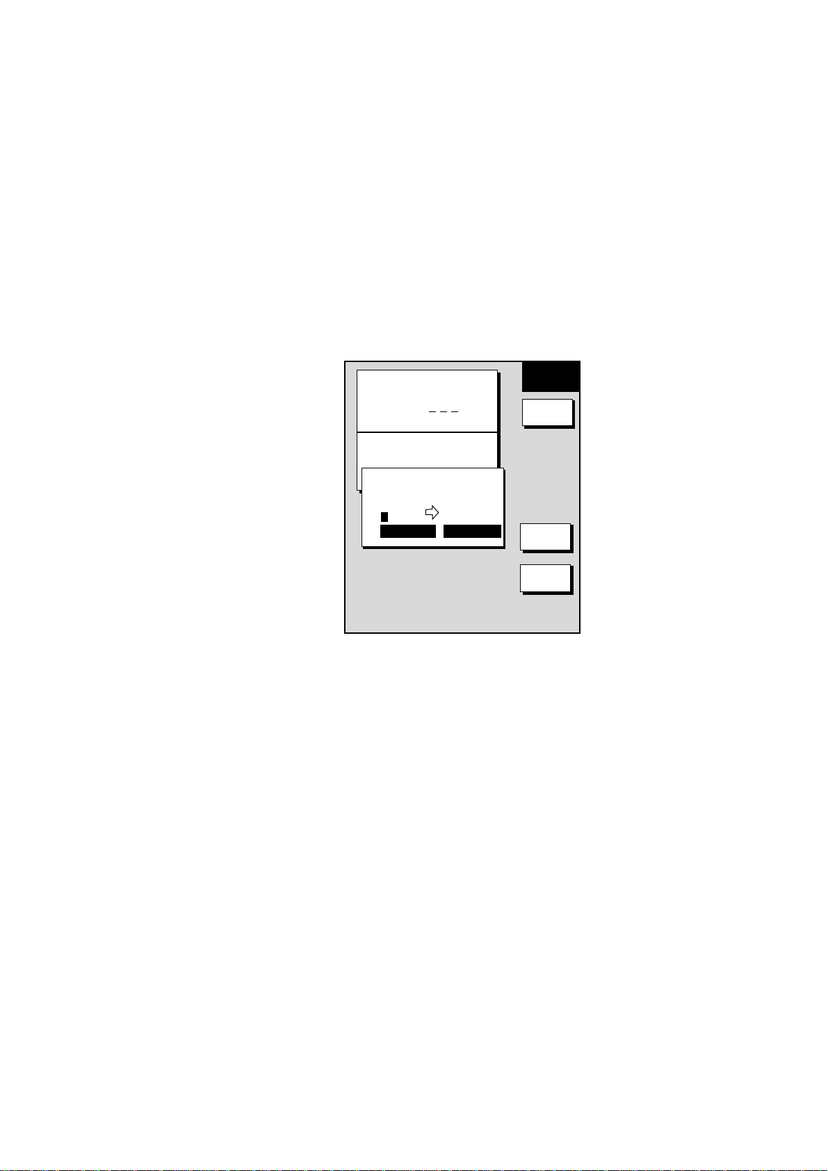
2.9.2 Connecting routes
Two routes which you have created can be connected as follows to form a new
route.
1. Press the [MENU] key to open the menu.
2. Press the WAYPOINTS/ROUTES soft key.
3. Press the ROUTES soft key.
4. Press the NEW ROUTE soft key.
5. If desired enter name and comment for route.
6. Press the CONNECT soft key.
7. Use the cursor pad and the [ENTER] knob to enter the route name for the
first route, beneath FIRST in the connect route window.
ROUTE NAME
2. PLOTTER OPERATION
NEW
ROUTE
0 0 1
COMMENT
CONNECT ROUTE
FIRST
_ _ _ _ _ _ _ _ _ _ _ _
FORWARD FORWARD
SECOND
F < -- > R
SAVE
CANCEL
Connect rout e window
8. If necessary press the F< - ->R soft key to select direction to follow the
waypoints of the route, forward or reverse.
9. Enter the route name of the second route as you did for the first route.
10. Press the SAVE soft key.
11. Press the [MENU] key to close the menu.
Note: The maximum number of waypoints in a route is 35. If this number is
exceeded an error message appears. In this case, delete waypoints in one
or both routes so the total number of waypoints does not exceed 35.
2-41
Page 76

2. PLOTTER OPERATION
2.9.3 Ins er ti ng wa ypoi n ts in a route
Waypoints can be inserted in a route as follows:
Inserting a waypoint from the route list
1. Press the [MENU] key to open the menu.
2. Press the WAYPOINTS/ROUTES soft key.
3. Press the ROUTES soft key.
4. Use the cursor pad to select a route.
5. Press the EDIT ROUTE soft key. The route name screen appears.
6. Press the LOCAL LIST soft key.
ROUTE NAME:
COMMENT:
01
001WPT
▲
34°44.111'N
135°21.134'W
02
003WPT
34°43.432'N
135°41.456'W
002WPT
03
34°14.124'N
135°21.567'W
04
005WPT
34°44.569'N
135°21.152'W
05
008WPT
34°54.124'N
135°21.888'W
001
LEG
29.9°
12.0nm
159.9°
6.00nm
50.5°
29.8nm
359.9°
3.0nm
EDIT
ROUTE
INSERT
WPT
REMOVE
WPT
CHANGE
WPT
COORD
TYPE
RETURN
Edit rout e menu
7. Press ▲ or ▼ to place the cursor at the location where you want to insert a
waypoint.
8. Press the INSERT WPT or CHANGE WPT soft key as appropriate. The local
waypoint list appears.
2-42
LOCAL LIST
001
002
003
004
001WPT
34°44.111'N
135°21.134'W
002WPT
34°43.432'N
135°41.456'W
003WPT
34°14.124'N
135°21.567'W
004WPT
34°34.490'N
135°51.387'W
▲
Waypoint list for editing a route (loc al list)
Page 77

2. PLOTTER OPERATION
9. Use the cursor pad to select the waypoint you want to insert. (You can switch
between the local list and alphanumeric list by using the LOCAL LIST and
ALPHA LIST soft keys.)
10. Press the SELECT WPT or CHANGE WPT soft key, whichever is displayed.
11. Press the [MENU] key to close the menu.
Inserting a waypoint from the plotter display
Inserti ng a waypoint before firs t waypoint or after last waypoint in a route
1. Press the [MENU] key to open the menu.
2. Press the WAYPOINTS/ROUTES soft key.
3. Press the ROUTES soft key.
4. Use the cursor pad to select a route.
5. Press the EDIT ROUTE soft key.
6. Press the PLOT soft key to show the plotter screen.
7. Operate the cursor pad to place the cursor on the first (or last) waypoint of
the route. A flashing diamond appears over the waypoint when it is correctly
selected.
8. Press the ADD TO START soft key or the ADD TO END soft key depending
on the waypoint you selected at step 7.
9. Operate the cursor pad to place the cursor on an existing waypoint (ADD
WPT soft key appears) or new location (ADD NEW WP soft key appears).
10. Press the ADD WPT soft key (ADD NEW WP soft key).
11. Press the [MENU] key to close the menu.
Inserti ng a waypoint in an interm ediate location on a route
1. Follow steps 1 through 6 in “Inserting a waypoint before the first or last
waypoint in a route.”
2. Operate the cursor pad to place the cursor on a line connecting waypoints.
The SPLIT LEG soft key appears and the line flashes when the line is
correctly selected.
3. Press the SPLIT LEG soft key. The line changes from solid to dashed.
4. The INSERT NEW WP soft key appears. Move the cursor to a new location
or select an existing waypoint, in which case the INSERT WPT key replaces
the INSERT NEW WP key.
5. Press the INSERT WPT soft key (INSERT NEW WP soft key).
6. Press the [MENU] key to close the menu.
2-43
Page 78

2. PLOTTER OPERATION
2.9.4 Removing waypoints from a route
Removing a waypoint from the route list
1. Press the [MENU] key to open the menu.
2. Press the WAYPOINTS/ROUTES soft key.
3. Press the ROUTES soft key.
4. Select a route.
5. Press the EDIT ROUTE and LOCAL LIST soft keys.
6. Select the waypoint you want to remove.
7. Press the REMOVE WPT soft key.
8. Press the [MENU] key to close the menu.
Removing a waypoint from the plotter display
1. Press the [MENU] key to open the menu.
2. Press the WAYPOINTS/ROUTES soft key.
3. Press the ROUTES soft key.
4. Select a route.
5. Press the EDIT ROUTE soft key.
6. Press the PLOT soft key to show the plotter screen.
7. Operate the cursor pad to place the cursor on the waypoint you want to
remove from the route.
8. Press the REMOVE WPT soft key. The route is redrawn, eliminating the
waypoint erased.
9. Press the [MENU] key to close the menu.
2.9.5 Erasing routes
1. Press the [MENU] key to open the menu.
2. Press the WAYPOINTS/ROUTES soft key.
3. Press the ROUTES soft key.
4. Use the cursor pad to select a route.
5. Press the ERASE ROUTE soft key. You are asked if you are sure to erase
the route.
6. Push the [ENTER] knob to erase the route, or the [CLEAR] key to escape.
7. Press the [MENU] key to close the menu.
2-44
Page 79
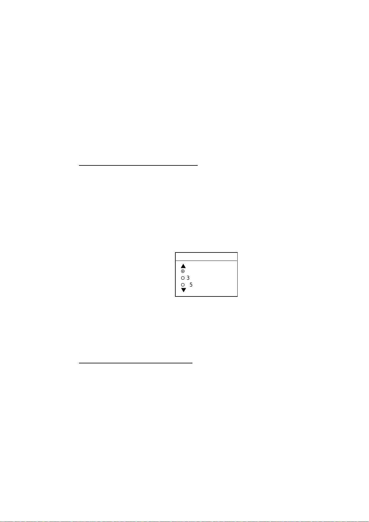
2.10 Navigation
This section shows you how to get to a desired destination by “quick points,”
waypoints, port services and routes.
Note: Reciprocal setting and canceling of destination is available by outputting
the data sentence ZDA from the NavNet unit connected to the navigator.
2.10.1 Navigating to a “quick point”
The “quick point” feature allows you to navigate to point(s) without retaining the
data indefinitely in your unit’s memory.
Selecting quick point entry method
You need to tell your unit how to set the quick point: 1 POINT, 35 POINTS (up to
35 points) or 35PTS/PORT SVC. (For how to navigate to points/port services
see “2.10.3 Navigating to ports, port services” on page 2-47.)
1. Press the [MENU] key.
2. Press the PLOTTER SETUP soft key.
3. Use the cursor pad to select SET GOTO METHOD, then press the EDIT soft
key.
2. PLOTTER OPERATION
GOTO METHOD
¤
1 POINT
¡
35 POINTS
¡
35PTS/PORT SVC
Goto method window
4. Use the cursor pad to select a method.
5. Press the ENTER soft key.
6. Press the [MENU] key to close the menu.
Navigating to a single quick point
1. Select “1 POINT” following the procedure in the above paragraph.
2. Place the cursor on an existing waypoint (GOTO WPT soft key appears) or a
new location (GOTO CURSOR soft key appears).
3. Depending on the selection you made at step 1, press the GOTO CURSOR
or GOTO WPT soft key.
A solid line (light-blue on the GD-1700C/1710C) with arrows connects between
own ship and destination, which is marked as “QP<01>” for cursor-selected
location or waypoint name in case of waypoint. Arrows on the line show the
direction to follow to get to the point. Range and bearing from own ship to the
destination appear at the top of screen. The quick point is saved to the waypoint
list as waypoint “QP01.”
2-45
Page 80

2. PLOTTER OPERATION
Navigating to multiple quick points
1. Select “35 POINTS” following the procedure in “Selecting quick point entry
method” on the previous page.
2. Press the GOTO soft key.
3. Place the cursor on an existing waypoint (SELECT WPT soft key appears) or
a new location (ADD QP soft key appears).
4. Depending on the action taken at step 3, press the SELECT WPT or ADD
QP soft key. “QP<01>” appears at the cursor location if a quick point is
selected. To erase last-entered quick point (waypoint), press the ERASE LST
QP (ERASE LST WP) soft key.
5. Repeat steps 3 and 4 to complete the route.
6. Push the [ENTER] knob to finish.
A solid line runs between own ship and first waypoint and a dashed line between
other waypoints. (For the GD-1700C/1710C, those lines are colored light-blue
and green, respectively.) Quick points are numbered in sequential order from
QP<01> and are saved to the waypoint list. Range and bearing from own ship to
the first destination appear at the top of screen. The quick points are saved as a
route, under the name “Q>RTE” (Quick Route).
2.10.2 Navigating to waypoints
Selecting a waypoint from the plotter display
1. Operate the cursor pad to select a waypoint.
2. Press the GOTO WPT soft key.
Note: GOTO method should be selected to “1 POINT” on the PLOTTER SETUP
menu.
Selecting a waypoint from the waypoint list
1. Press the [MENU] key to open the menu.
2. Press the WAYPOINTS/ROUTES soft key.
3. Press the WAYPOINTS soft key to open the waypoint menu.
4. Press the LOCAL LIST or ALPHANUMERIC LIST soft key as desired.
5. Use the cursor pad to select a waypoint.
6. Press the GOTO soft key, and the plotter display appears.
For either of the above methods, a solid line (light-blue on the
GD-1700C/1710C) runs between waypoint selected and own ship’s position.
Arrows on the line show the direction to the follow to get to the waypoint.
Waypoint data appears at the top of screen.
2-46
Page 81

2. PLOTTER OPERATION
Selecting an external waypoin t
You can select a waypoint (or route) entered at an external plotter connected
with NMEA cable. This function requires RMB sentence.
1. Press the [MENU] key, PLOTTER SETUP soft key to show the PLOTTER
SETUP menu.
2. Use the trackball to select QP.
3. Press the ENTER soft key or [ENTER] key to show the QP window.
QP
¡
EXT WPT (RMB)
¤
INTERNAL
QP window
4. Select EXT WPT (RMB).
5. On a connected external plotter, set a waypoint (or route) as the destination.
Selected waypoint (route) appears on the NavNet plotter screen. (on radar
screen, a lollipop appears to show the waypoint.)
2.10.3 Navigating to ports, port services (NavCharts™ only)
NavCharts™ have a port service list which shows services available at ports or
harbors. (See page 2-13.) You can use the list to set your destination as follows:
1. Select “35 PTS/PORT SVC” following the procedure in “Selecting quick point
entry method” on page 2-45.
2. Place the cursor on the location desired, then press the GOTO soft key. Then,
soft key titles change as in the figure below.
40°45.971'N
+
13°57.462'E
16.0nm
PUNTA CORNACCHIA
ACCO AMENO
CASAMICCIOLA
I. ISCHIA
FROM
OS
ISCHIA
PORTO
0.26 nm
180.2°
M
GOTO
QUICK
ROUTE
NEAR
SRVC
PORT
CANCEL
GOTO
Plotter display
3. Press the PORT or NEAR SRVC soft key depending on objective. PORT
shows a list of ports in your area. NEAR SRVC displays the port service list.
2-47
Page 82

2. PLOTTER OPERATION
PORT & SERVICE
▼
SELECT PORT & SRVC
▲
ACCIAROLI
ACQUAMORTA
¤
¡
¡
¡
¡
¡
¡
¡
AGNONE S. NICOLA
AGROPOLI
AMALFI
BAIA
CAPRI
CASA MICCIOLA-ISCHIA
Port list (NavChart , Italy)
PORT & SERVICE
WC
TM
▼
Port services (NavChart )
TM
Port services (C-MAP)
Port services and sample port lis t
4. If you selected PORT (NavCha rt s™ only) at step 3, use the cursor pad to
select a port and press the ENTER soft key. Make a route using the soft keys,
then push the [ENTER] knob. (If you want to go directly to that port, simply
press the ADD QP soft key followed by the [ENTER] knob.)
If you sel ect ed NE AR SRVC at step 3, select service mark desired with the
cursor pad, then press the ENTER soft key or the [ENTER] knob. Then, the
display shows the locations of those services nearest you. (The figure below
shows the location of filling stations in an area in southern Italy.) Use the
cursor pad to place the “hand cursor” on the port service icon desired and
press the ENTER soft key. Make a route using the soft keys, then push the
[ENTER] knob. (If you want to go directly to location selected, simply press
the ADD QP soft key followed by the [ENTER] knob.)
40°45.971'N
+
13°57.462'E
16.0nm
PUNTA CORNACCHIA
ACCO AMENO
CASAMICCIOLA
I. ISCHIA
FROM
OS
ISCHIA
PORTO
0.26 nm
180.2°M
GOTO
ENTER
CANCEL
GOTO
2-48
Sample filling stat ion locations ( s outhern It aly )
Page 83

2.10.4 Following a route
Selecting the rout e to follow
1. Press the [MENU] key to open the menu.
2. Press the WAYPOINTS/ROUTES soft key.
3. Press the ROUTES soft key to open the route list.
4. Select a route.
5. Press the GOTO soft key to show the plotter display. The cursor is on the
waypoint nearest own ship.
FISH
16.0 nm
359.2°M 104.5°M
83.2nm 10.0 kt
2. PLOTTER OPERATION
GOTO
ROUTE
WP-002
FISH
WP-001
CRAB
GOTO
WPT
RVRSE
ROUTE
RETURN
Plotter di s play , r oute select ed as desti nation
6. Operate the cursor pad to place the cursor on the waypoint or leg in the route
from where to start navigating the route.
7. Press the GOTO WPT or FOLLOW LEG soft key, depending on the action
taken at step 6.
A solid line runs between own ship and the first waypoint and all other waypoints
are connected with a dashed line. (For the GD-1700C/1710C, those lines are
colored light-blue and green, respectively.) The arrows on the lines show the
direction to traverse the route.
Navigatin g waypoints in reverse order
Press the RVRSE ROUTE soft key to navigate waypoints in reverse order. The
arrows on the route line point in the direction selected.
2-49
Page 84

2. PLOTTER OPERATION
Restarting navigation
When you steer to avoid an obstacle or the vessel drifts, you may go off your
intended course, as in Line 1 in the figure below. Also, if you don’t need to return
to the original course, you can go directly to the next waypoint, as in Line 2 in
the figure below. In these cases, use the restart function to restart navigation.
Line 2
Obstacle
Line 1
Original course
Exam ple of when to restart navigation
1. Press the [MENU] key to open the menu.
2. Press the WAYPOINTS/ROUTES soft key.
3. Press the LOG soft key.
Destination waypoint (WPT name against bright background)
Passed waypoint (green characters)
Estimated Time of Arrival at destination
ETA 23:59 11.FEB
LEG
29.9°
12.0nm
159.9°
6.00nm
50.5°
29.8nm
359.9°
3.0nm
Replaces triangle
when selecting a
route leg.
01
001WPT
34°44.111'N
135°21.134'W
02
▲
34°43.432'N
135°41.456'W
002WPT
03
34°14.124'N
135°21.567'W
04
005WPT
34°44.569'N
135°21.152'W
05
008WPT
34°54.124'N
135°21.888'W
003WPT
LOG
RESTART
STOP
RVRSE
SPEED
COORD
TYPE
Replaced by
"FOLLOW LEG"
when selecting
a route leg.
2-50
Log display
4. Use the cursor pad to select a waypoint or a route leg. When a route leg is
selected the single arrow cursor is replaced by double arrows.
5. Press the RESTART soft key, or FOLLOW LEG soft key in case of route leg.
Note: Navigation may be restarted from the plotter display, with the
RESTART key, when a single quick point (QP<01>) is selected for
navigation.
6. Press the [MENU] key to close the menu.
Page 85

2. PLOTTER OPERATION
Setting sp eed for ETA calculation
Speed, which may be input manually or automatically, is required to calculate
ETA (Estimated Time of Arrival) to a destination.
1. Press the [MENU] key to open the menu.
2. Press the WAYPOINTS/ROUTES soft key.
3. Press the LOG soft key.
4. Press the SPEED soft key.
SPEED FOR ETA
▲
¤
SPD 010.0kt
¡
GPS AVG. SPEED
▼
Select speed for ETA window
5. Enter speed manually in the SPD field, or use GPS speed data (if applicable)
by selecting GPS AVG. SPEED.
6. Press the ENTER soft key or the [ENTER] knob to register your selection.
7. Press the [MENU] key to close the menu.
Switching waypoints
When you arrive to a waypoint on a route, you can switch to the next waypoint
by one of the three methods below.
PERPENDICULAR: Automatically switches the TO waypoint when the boat
passes an imaginary perpendicular line passing through the center of the
destination waypoint.
ARR VL A L M CRCL: Automatically switches the TO waypoint when the boat
comes within the arrival alarm range. For how to set the arrival alarm, see the
paragraph “2.11.2 Arrival alarm.”
MANUAL: The destination waypoint may be manually switched by using the
RESTART soft key (see page 2-50). This function is operative when “1 POINT” is
selected as the GOTO method (see page 2-45).
WPT 2
Waypoint switched
at this point.
WPT 2
Waypoint switched
at this point.
WPT 1
Perpendicular
WPT 1
Arrival Alarm Circle
Automatic waypoint switching methods
2-51
Page 86

2. PLOTTER OPERATION
To select waypoint switching method do the following:
1. Press the [MENU] key.
2. Press the PLOTTER SETUP soft key.
3. Use the cursor pad to select WAYPOINT SWITCHING.
4. Press the EDIT soft key to show the waypoint switching window.
5. Use the cursor pad to select appropriate waypoint switching method;
PERPENDICULAR, ARRVL ALM CRCL (default setting), or MANUAL.
6. Press the ENTER soft key or [ENTER] knob.
7. Press the [MENU] key to close the menu.
2.10.5 Cancelling route navigation
1. Press the [MENU] key to open the menu.
2. Press the WAYPOINTS/ROUTES soft key.
3. Press the LOG soft key.
4. Press the STOP soft key.
5. Push the [ENTER] knob.
6. Press the RELEASE soft key.
2-52
Page 87

2.11 Alarms
The plotter section has eight conditions which generate both audio and visual
alarms: arrival alarm, anchor watch alarm, XTE (Cross Track Error) alarm,
proximity alarm, speed alarm, trip alarm, water temperature alarm and bottom
alarm. (The bottom and water temperature alarms, which require depth and
water temperature data, may also be set on the sounder alarm menu. For these
alarms see Chapter 4.)
You may set up the plotter alarms on the ALARM menu, which may be displayed
by pressing the [ALARM] key.
2. PLOTTER OPERATION
AUDIO ALARM
INTERNAL BUZZ
ARRIVAL ALARM
OFF 0.010nm
ANCHOR WATCH ALARM
OFF 0.010nm
PROXIMITY ALARM
OFF
XTE ALARM
OFF 0.050nm
SPEED ALARM
OFF
TRIP ALARM
OFF 0000.0nm
ALARM INFORMATION
NO ALARM
Page 1 Page 2
2.11.1 Audio alarm on/off
ALARM1
EDIT
NEXT
PAGE
CLEAR
ALARM
NEXT
PAGE
RETURN
PREV.
PAGE
Plotter alarm menu
BOTTOM ALARM
TEMPERATURE ALARM
ALARM INFORMATION
NO ALARM
OFF
OFF
ALARM
EDIT
CLEAR
ALARM
PREV.
PAGE
2
Audio and visual alarms are released whenever an alarm setting is violated. You
can enable or disable the audio alarm as follows:
1. Press the [ALARM] key to show the alarm menu.
2. Use the cursor pad to select AUDIO ALARM.
3. Press the EDIT soft key to show the audio alarm window.
AUDIO ALARM
¡
INT & EXT BUZZ
¤
INTERNAL BUZZ
¡
OFF
Audio alarm window
4. Use the cursor pad to select INT & EXT BUZZ (Internal + External alarm),
INTERNAL BUZZ (Internal alarm) or OFF. This turns on or off the audio
alarm globally for all alarms, including radar.
5. Press the ENTER soft key followed by the [ALARM] key to close the menu.
2-53
Page 88

2. PLOTTER OPERATION
2.11.2 Arrival alarm
The arrival alarm informs you that your boat is approaching a destination
waypoint. The area that defines an arrival zone is that of a circle which you
approach from the outside of the circle. The alarm will be released if your boat
enters the circle. When the arrival alarm is active a dashed circle (red on the
GD-1700C/1710C) marks the arrival alarm area.
Note: Arrival alarm and anchor watch alarm cannot be set together.
Own ship
Alarm
range
: Alarm area
Destination
waypoint
How the arrival alarm works
1. Press the [ALARM] key to open the alarm menu.
2. Use the cursor pad to select ARRIVAL ALARM.
3. Press the EDIT soft key to show the arrival alarm window.
ARRIVAL ALARM
▲
¡
ON 0.010nm
¤
OFF
▼
Arrival alarm wi ndow
4. Use the cursor pad to select ON.
5. Use the cursor pad and [ENTER] knob to enter alarm range: Use ◄ or ► to
select digit; rotate the [ENTER] knob to set value. The available arrival alarm
range is 0.001 to 9.999 miles.
6. Press the ENTER soft key or push the [ENTER] knob to register setting.
7. Press the [ALARM] key to close the menu.
2-54
Page 89

2.11.3 Anchor watch alarm
The anchor watch alarm informs you that your boat is moving when it should be
at rest. When the anchor watch is active, a dashed circle (red on the
GD-1700C/1710C) with an “X” at its center marks the anchor watch area.
Your ship's position where
you start the anchor watch
alarm.
2. PLOTTER OPERATION
Alarm
setting
: Alarm
area
How the ancho r watch alarm works
1. Press the [ALARM] key to open the alarm menu.
2. Use the cursor pad to select ANCHOR WATCH ALARM.
3. Press the EDIT soft key to open the anchor alarm window.
ANCHOR WATCH ALARM
▲
¡
ON 0.050nm
¤
OFF
▼
Anchor watc h alarm window
4. Use the cursor pad to select ON.
5. Use the cursor pad and [ENTER] knob to enter alarm range: Use ◄ or ► to
select digit; rotate the [ENTER] knob to set value. The available anchor
watch range is 0.001 to 9.999 miles.
6. Press the ENTER soft key or push the [ENTER] knob to register setting.
7. Press the [ALARM] key to close the menu.
Note: If the arrival alarm range is changed, turn off the anchor watch alarm and
then turn it on again to give priority to the anchor watch alarm.
2-55
Page 90
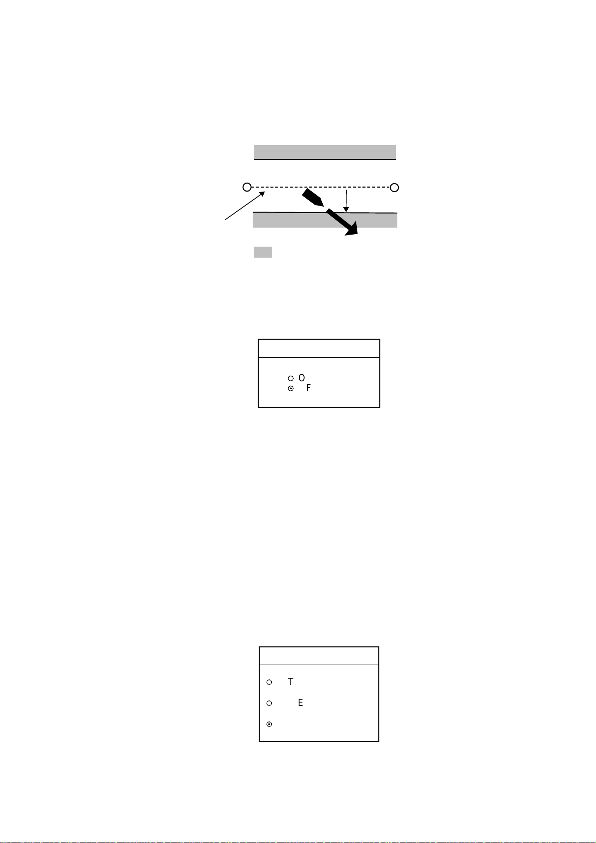
2. PLOTTER OPERATION
2.11.4 XTE (Cross Track Error) alarm
The XTE alarm warns you when your boat is off its intended course. When the
XTE alarm is active two dashed lines (red on the GD-1700C/1710C) mark the
XTE alarm area.
Own ship
position
Intended
course
Alarm
setting
: Alarm
Destination
waypoint
How the XTE alar m works
1. Press the [ALARM] key to open the alarm menu.
2. Use the cursor pad to select XTE ALARM.
3. Press the EDIT soft key to open the XTE alarm window.
XTE ALARM
▲
¡
ON 0.050nm
¤
OFF
▼
XTE alarm window
4. Use the cursor pad and [ENTER] knob to enter alarm range: Use ◄ or ► to
select digit; rotate the [ENTER] knob to set value. The available XTE alarm
range is 0.001 to 9.999 miles.
5. Press the ENTER soft key or push the [ENTER] knob to register setting.
6. Press the [ALARM] key to close the menu.
2.11.5 Speed alarm
The speed alarm warns when your boat’s speed is within or under/over the
speed range set.
1. Press the [ALARM] key to open the alarm menu.
2. Use the cursor pad to select SPEED ALARM.
3. Press the EDIT soft key to display the speed alarm window.
2-56
SPEED ALARM
▲
¡
WITHIN
000.0 ~ 000.0 kt
¡
UNDER/OVER
000.0 ~ 000.0 kt
¤
OFF
▼
Speed alarm wi ndow
Page 91

4. Use the cursor pad to select WITHIN, UNDER/OVER, or OFF.
5. For WITHIN and UNDER/OVER, use the cursor pad and [ENTER] knob to
enter alarm range: Use ◄ or ► to select digit; rotate the [ENTER] knob to set
value.
6. Press the ENTER soft key or push the [ENTER] knob to register setting.
7. Press the [ALARM] key to close the menu.
2.11.6 Proximity alarm
The proximity alarm alerts you when own ship nears a waypoint, which is
marked with the proximity mark, by the proximity alarm radius set for that
waypoint on the waypoint list. When own ship is within a waypoint’s proximity
alarm radius, the alarm sounds. The proximity mark remains on the screen until
the proximity alarm is turned off or the waypoint is erased. (Note that the
GD-1700C/1710C shows the proximity mark in red.)
2. PLOTTER OPERATION
Radius in proportion to
proximity alarm radius,
which is set on waypoint list
001WPT
Proximity mark
1. Press the [ALARM] key to open the alarm menu.
2. Use the cursor pad to select PROXIMITY ALARM.
3. Press the EDIT soft key to show the proximity alarm window.
PROXIMITY ALARM
▲
¤
ON
¡
OFF
▼
Proximity alarm window
4. Use the cursor pad to select ON or OFF.
5. Press the ENTER soft key or [ENTER] knob.
6. Press the [ALARM] key to close the menu.
2-57
Page 92

2. PLOTTER OPERATION
2.11.7 Trip alarm
The trip alarm informs you when you have traveled a certain distance.
1. Press the [ALARM] key to open the alarm menu.
2. Use the cursor pad to select TRIP ALARM.
3. Press the EDIT soft key to show the trip alarm window.
4. Select ON with the cursor.
5. Use the cursor pad and [ENTER] knob to enter alarm range: Use ◄ or ► to
select digit; rotate the [ENTER] knob to set value.
6. Press the ENTER soft key or push the [ENTER] knob to register setting.
7. Press the Press the [ALARM] key to close the menu.
TRIP ALARM
▲
¡
ON 0000.0nm
¤
OFF
▼
Trip alarm window
2-58
Page 93
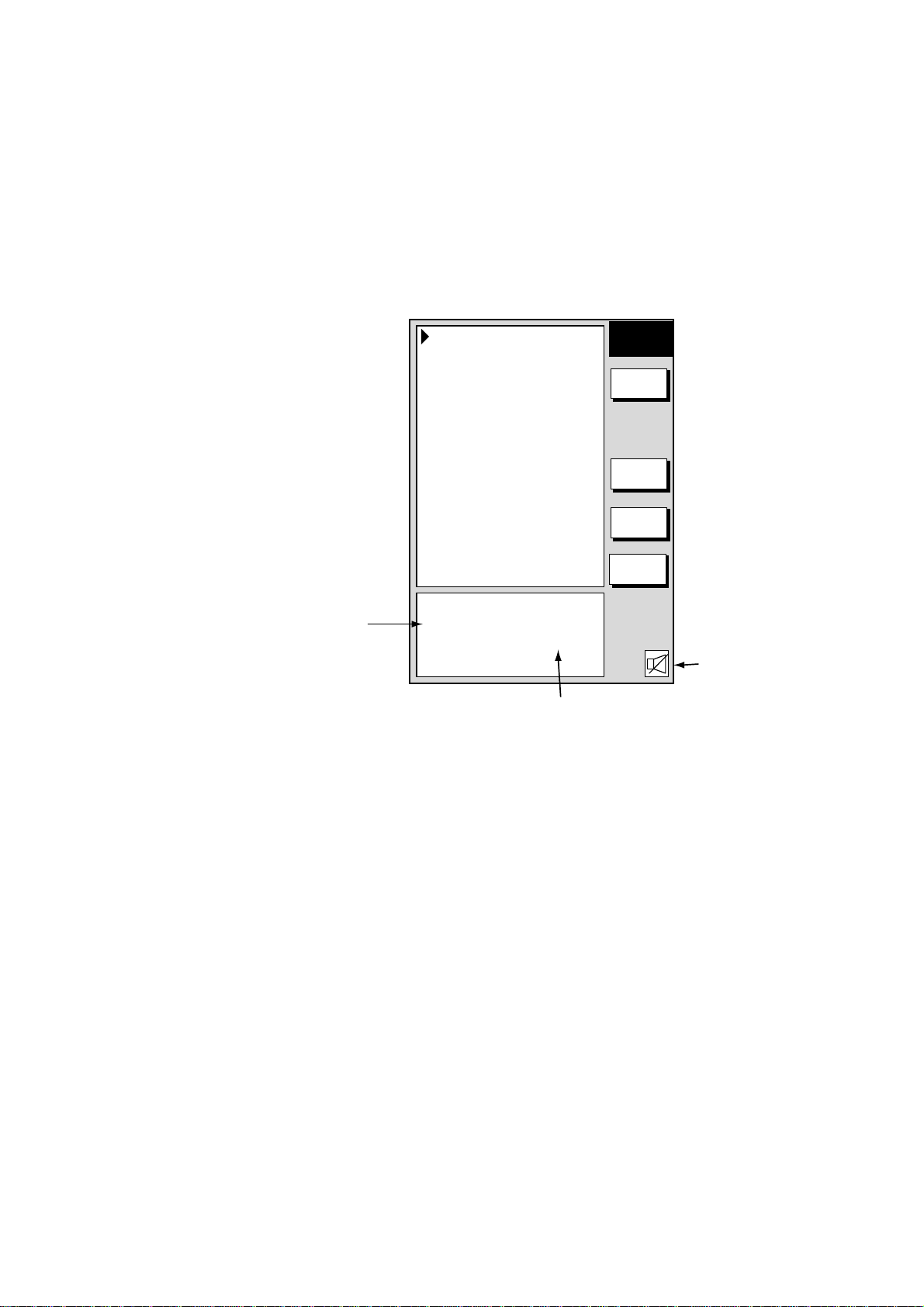
2.11.8 Alarm information
When an alarm setting has been violated, the buzzer sounds and the speaker
icon appears, in red on the color model. Press the [CLEAR] key to silence the
alarm. You can see which alarm has been violated on the ALARM menu. In the
example below the arrival alarm has been violated.
1. Press the [ALARM] key. The name of the offending alarm is shown in the
alarm information window.
2. PLOTTER OPERATION
Alarm information
window
AUDIO ALARM
INT & EXT BUZZ
ARRIVAL ALARM
ON 0.010nm
ANCHOR WATCH ALARM
OFF 0.010nm
PROXIMITY ALARM
OFF
XTE ALARM
OFF 0.050nm
SPEED ALARM
OFF
TRIP ALARM
OFF 0000.0nm
ALARM INFORMATION
ARRIVED
AT WAYPOINT XXX!
ALARM1
EDIT
CLEAR
ALARM
NEXT
PAGE
RETURN
Speaker icon
XXX = Destination waypoint name
Alarm menu
2. Press the CLEAR ALARM soft key to acknowledge the alarm (and silence the
alarm if it was not done with the [CLEAR] key). For the color model, the
speaker icon changes from red to background color. The speaker icon
remains on the screen until the reason for the alarm is eliminated or the
alarm is disabled. If more than one alarm has been violated the message
CONTINUE appears at the bottom of the alarm information window. In this
case, press the NEXT INFO soft key to see which other alarms have been
violated.
Note: For the color model, the alarm icon is red when an alarm setting is
violated, and changes to background color when the [CLEAR] key or
CLEAR ALARM soft key is pressed. The color does not change
regardless of how many other alarms are violated.
3. Press the [ALARM] key to close the alarm menu.
2-59
Page 94
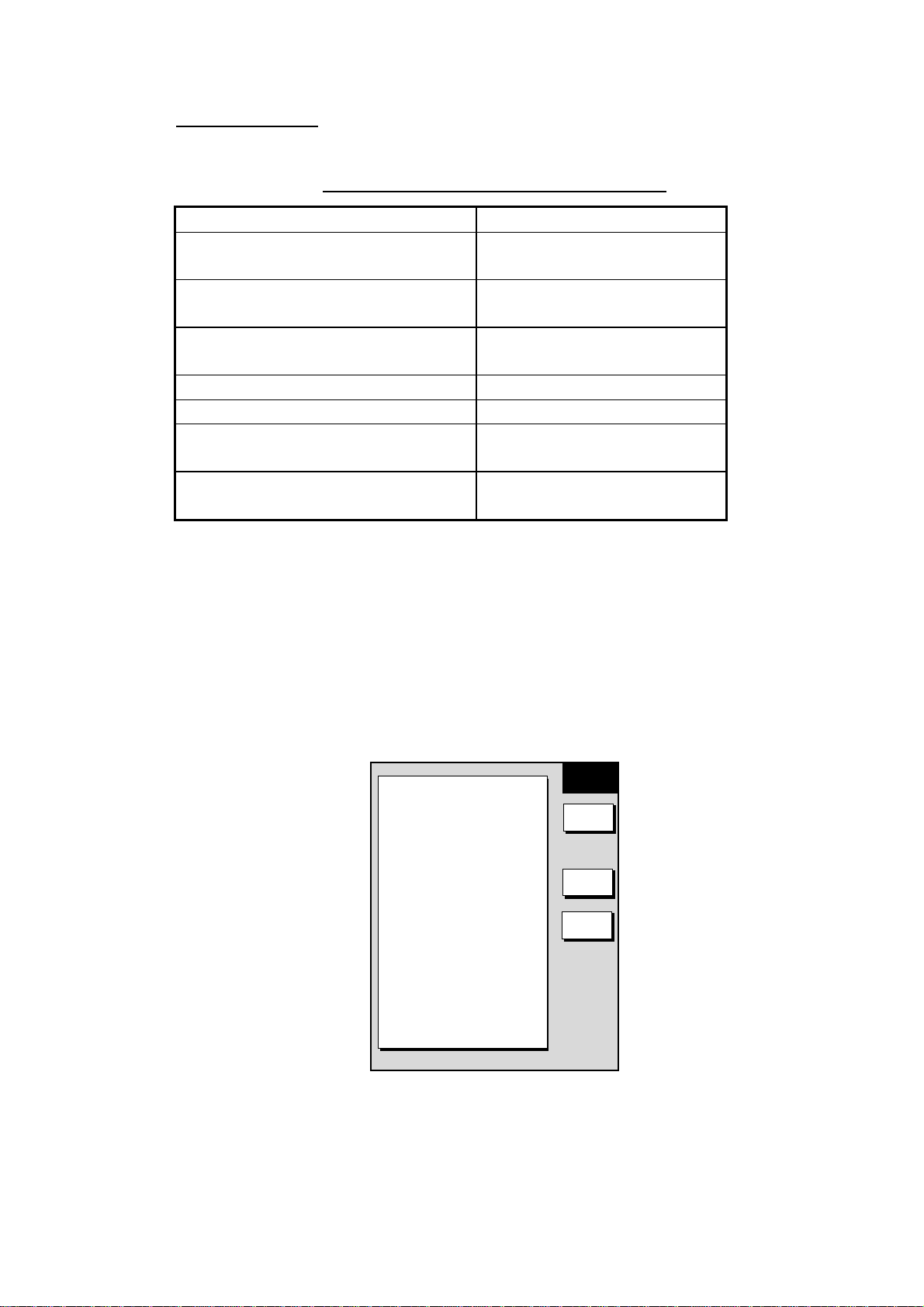
2. PLOTTER OPERATION
Alarm messages
The table below shows the plotter alarm messages and their meanings.
Plotter alarm messages and their meanings
Message Meaning
ARRIVED AT XXX WAYPOINT!
(XXX = waypoint name)
ENTERED INTO AVOIDANCE
AREA!
EXCEEDED ANCHOR WATCH
LIMIT!
EXCEEDED XTE LIMIT! XTE alarm violated.
SPEED ALARM! Speed alarm violated.
TEMPERATURE ALARM! Water temperature alarm
TRIP ALARM! MILEAGE
EXCEEDED
2.12 Resetting Trip Distance
Trip distance is shown on the navigation data display. You can reset the trip
distance to zero as follows:
1. Press the [MENU] key.
2. Press the SYSTEM CONFIGURATION and GENERAL SETUP soft keys in
that order to show the GENERAL SETUP menu.
Arrival alarm violated.
Proximity alarm violated.
Anchor watch alarm violated.
violated.
Trip alarm violated.
▲
KEY BEEP
ON
LANGUAGE
ENGLISH
RANGE UNIT
nm, kt
TEMPERATURE UNIT
°
F
DEPTH UNIT
ft
TEMPERATURE SOURCE
NMEA
DEPTH SOURCE
NMEA
RESET TRIP LOG
NO
GENERAL
SETUP1
EDIT
NEXT
PAGE
RETURN
General set up menu, page 1
3. Use the cursor pad to select RESET TRIP LOG, then press the EDIT soft key.
4. Use the cursor pad to select YES.
5. Press the ENTER soft key.
6. Press the [MENU] key to close the menu.
2-60
Page 95
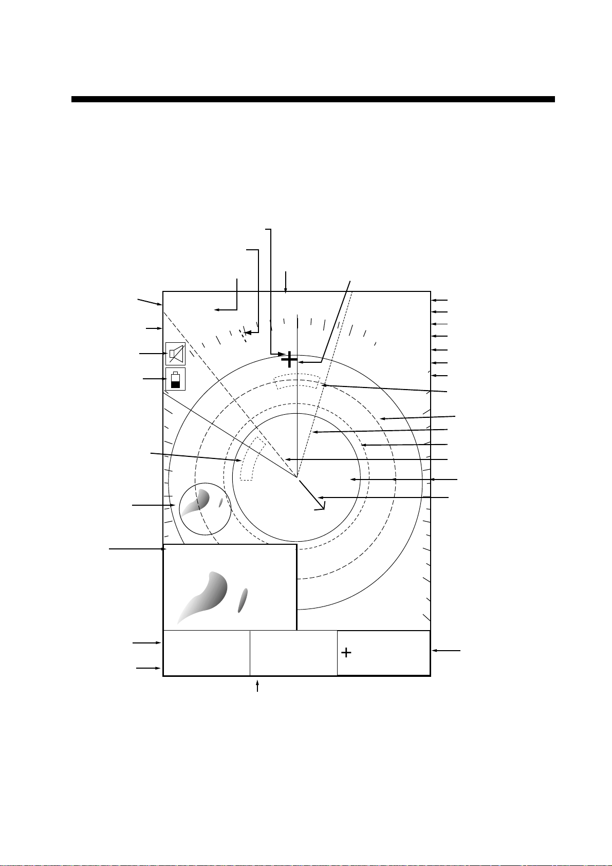
3. RADAR OPERATION
This chapter covers radar operation, including the ARP (Auto Plotter) function.
ARP requires a Model 1800/1900 series network radar equipped with the ARP
circuit board.
3.1 Radar Display
Range/
range ring
interval
Presentation
mode
Alarm icon
Battery icon
Guard zone 1
Zoom area
Cursor
North marker
Pulselength
.125nm
.250
. / 319.9
SP
H-UP
Heading
M: Magnetic
T: True
°M
Heading line
TRAIL 30m
02m30s
G1 IN
G2 OUT
ES L
EAV L
IR L
Trail time
Trail elapsed time
Guard zone 1
Guard zone 2
Echo stretch
Echo averaging*
Interference rejector
Guard zone 2
VRM2
EBL1
VRM1
EBL2
Range ring
Own ship vector
(ARP required*,
true vector mode)
Zoom
window
EBL1 range
VRM1 range
EBL1
27.0°R
VRM1
0 .158nm
EBL2
327.1°R
VRM2
0 .225nm
EBL2 bearing, VRM2 range
Radar display
359.9°R
0.240nm
* = Radar source
Model 1800/1900
series radar
Cursor range
and bearing
(Cursor position may
also be shown, in
L/L or Loran C TD.)
3-1
Page 96

3. RADAR OPERATION
3.2 Transmitting, Stand-by
1. Confirm that the network radar is plugged in.
2. Press the [DISP] key to select a radar display.
3. Press the [POWER/BRILL] key momentarily.
4. Press the RADAR STBY soft key to highlight TX on its label.
5. Press the RETURN soft key.
When the radar picture is not required, but you want keep it in a state of
readiness, press the RADAR TX soft key to highlight STBY on its label.
3.3 Tuning
The radar receiver can be tuned automatically or manually, and the default
tuning method is automatic. If you require manual tuning, do the following
:
1. Press the [MENU] key to display the main menu.
2. Press the RADAR DISPLAY SETUP soft key.
3. Select TUNING, then press the EDIT soft key.
TUNING
¤
AUTO
¡
MAN
4. Choose MAN.
5. Adjust the [ENTER] knob so the tuning bar is at its longest position.
6. Press the RETURN soft key.
7. Press the [MENU] key to close the menu.
Note: If the auto setting does not provide satisfactory tuning, ask your dealer
how to re-adjust tuning.
3.4 Adjusting the Gain
The [GAIN] key adjusts the sensitivity of the radar receiver. It works in a manner
similar to the volume control of a broadcast receiver, which amplifies received
signals.
The proper setting is such that the background noise is just visible on the screen.
If your gain setting is too low, weak echoes may be missed. On the other hand,
excessive gain yields too much background noise; strong targets may be missed
because of the poor contrast between desired echoes and the background noise
on the display.
To adjust the receiver sensitivity, transmit on long range, and then do the
following:
Tuning bar
Tuning window
3-2
Page 97

3. RADAR OPERATION
1. Press the [GAIN] key. The last-used “adjustment window” is displayed. In the
example below, the gain sensitivity adjustment window is shown. The gain
soft keys shown depend on radar source as shown below.
Item selected for adjustment is highlighted.
.125nm
SP
.250/ 319.9
H-UP
M
°
GAIN
ADJUST
.125nm
SP
.250/ 319.9
H-UP
M
°
GAIN
ADJUST
GAIN SENSITIVITY
¤
AUTO ROUGH
¡
AUTO MODERATE
¡
AUTO CALM
¡
MAN
GAIN
A/C
SEA
A/C
RAIN
FTC
RETURN
359.9°R
0
+
0.240nm
GAIN SENSITIVITY
¤
AUTO ROUGH
¡
AUTO MODERATE
¡
AUTO CALM
¡
MAN
0
GAIN
A/C
SEA
A/C
RAIN
A/C AT
ON /OFF
RETURN
359.9°R
+
0.240nm
Model 1700 series radar Model 1800/1900 series radar
Gain adjustment soft keys
2. If the gain sensitivity window is not displayed, press the GAIN soft key to
show it.
GAIN SENSITIVITY
¤
AUTO ROUGH
¡
AUTO MODERATE
¡
AUTO CALM
¡
MAN
0
Gain sensitivit y window
3. Press ▲ or ▼ to select AUTO ROUGH, AUTO MODERATE, AUTO CALM, or
MAN (manual) as appropriate. Select an AUTO option according to the sea
state.
4. For manual adjustment, rotate the [ENTER] knob to adjust. The range of
adjustment is 0-100.
5. Press the [GAIN] key on the front panel or the RETURN soft key to finish.
3-3
Page 98

3. RADAR OPERATION
3.5 Reducing Sea Clutter
3.5.1 How th e A/C SEA works
Echoes from waves can be troublesome, covering the central part of the display
with random signals known as “sea clutter”. The higher the waves and the higher
the antenna above the water, the further the clutter will extend. Sea clutter may
affect radar performance because real targets are sometimes hidden by the
echoes of small waves. (See the left-hand figure in the figure below.) When sea
clutter masks the picture, adjust the A/C SEA to reduce the clutter.
The A/C SEA reduces the amplification of echoes at short ranges (where clutter
is the greatest) and progressively increases amplification as the range increases,
so amplification will be normal at those ranges where there is no sea clutter.
Sea clutter at
screen center
3.5.2 Adjusting A/C SEA
A/C SEA should be adjusted so that the clutter is broken up into small dots, and
small targets become distinguishable.
1. Press the [GAIN] key.
2. Press the A/C SEA soft key to show the A/C SEA setting window.
A/C SEA
¡
AUTO ROUGH
¡
AUTO MODERATE
¡
AUTO CALM
¤
MAN
Model 1700 series radar
3. When the radar source is the Model 1700 series radar, press ▲ or ▼ to
select AUTO ROUGH, AUTO MODERATE, AUTO CALM, or MAN (manual)
as appropriate. Select an AUTO option according to the sea state.
4. For manual adjustment, rotate the [ENTER] knob to adjust while observing
radar echoes. The range of adjustment is 0-100. Do not overadjust the A/C
SEA – weak target echoes may be missed.
0
A/C SEA adjusted;
sea clutter suppressed
Effect of A/C SEA
Model 1800/1900 series radar
A/C SEA setting window
A/C SEA
0
3-4
Page 99

5. When the radar source is the Model 1800/19 00 series radar, A/C SEA and
A/C RAIN can be automatically adjusted. Press the A/C AT soft key to select
ON or OFF as appropriate. When turned on, it overrides A/C SEA and A/C
RAIN settings.
6. Press the [GAIN] key on the front panel or RETURN soft key to finish.
3.6 Reducing Precipitation Clutter
The vertical beamwidth of the antenna is designed to see surface targets even
when the ship is rolling. However, by this design the unit will also detect
precipitation clutter (rain, snow, hail, etc.) in the same manner as normal targets.
Precipitation clutter shows as random dots on the screen.
3.6.1 Adjusting the A/C RAIN
When echoes from precipitation mask solid targets, adjust the A/C RAIN to split
up these unwanted echoes into a speckled pattern, making recognition of solid
targets easier.
1. Press the [GAIN] key.
2. Press the A/C RAIN soft key to show the A/C RAIN window.
3. RADAR OPERATION
A/C RAIN
0
A/C RAIN set ting window
3. Rotate the [ENTER] knob to adjust the A/C RAIN. The current level is shown
on the A/C RAIN level bar in the A/C RAIN window, and the range of
adjustment is 0 to 100(%). Do not overadjust the A/C RAIN – weak target
echoes may be missed.
4. Press the [GAIN] key on the front panel or RETURN soft key to finish.
3-5
Page 100

3. RADAR OPERATION
3.6.2 Adjusting the FTC
To suppress rain clutter from heavy storms or scattered rain clutter, adjust the
FTC, which is available with the Model 1700 series network radar. The FTC
splits up these unwanted echoes into a speckled pattern, making recognition of
solid targets easier.
Note: In addition to reducing clutter, the FTC can be used in fine weather to
clarify the picture when navigating in confined waters. However, with the
circuit active the receiver is less sensitive. Therefore, turn off the FTC, by
setting it for “0”, when its function is not required.
1. Press the [GAIN] key.
2. Press the FTC soft key to show the FTC window.
FTC
0
FTC sett ing window
3. Rotate the [ENTER] knob to adjust. The range of adjustment is 0-100(%). Do
not overadjust the FTC – weak target echoes may be missed.
4. Press the [GAIN] key on the front panel or RETURN soft key to finish.
3-6
 Loading...