

Page 1

OPERATOR'S MANUAL
KU-BAND ANTENNA
Model
FV-110
www.furuno.com
Page 2

The paper used in this manual
9-52 Ashihara-cho,
A:SEP
2015
.
B:FEB.21, 2017
Pub. No.
(
)
Nishinomiya, 662-8580, JAPAN
is elemental chlorine free.
・FURUNO Authorized Distributor/Dealer
All rights reserved.
YOTA
FV-110
Printed in Japan
OME-50990-B
0 0 0 1 9 1 0 1 1 1 1
Page 3

KU-BAND ANTENNA FV-110
Quick guide
Introduction
This quick guide aims at experienced service personnel who have installed the FV-110 system and
connected power. It lists the minimum configuration tasks you have to make before the system. can be
used on-air on a satellite.
Prerequisites
1. Connect a PC to the front LAN connector or the LAN3 connector at the rear of the Antenna Control
Unit.
2. Open an Internet Browser and type the default IP address of the FV-110: http://192.168.0.1 to access
the web interface.
Configuration tasks (minimum)
Configuration task What to do and where to find more information
Heading input
Azimuth calibration
TX cable calibration
Modem connection
Modem profile
Network settings
Configure the heading input to External under SETTINGS >
Navigation. For more information see Table 5-1 on page 5-4.
Connect the ship’s heading (RS-422, NMEA0183) to the NMEA 0183
multi-connector. Pin 8 Ship Ground/Shield (connect only one end), Pin 9
Line B +, and Pin 10 Line A-. For more information see NMEA 0183
connector on page 3-3.
Make an azimuth calibration under SERVICE > Calibration to ensure
that the FV-110 can point and receive satellite signal. For more
information see Azimuth calibration on page 5-7.
Make a Tx cable calibration under SERVICE > Calibration to ensure
that Tx power is calibrated at all frequencies. For more information see
Cable calibration on page 5-11.
See Appendix E or http://www.lyngsat.com for DVB-S transponder
information.
Connect cables between the modem and the ACU. For more information
see VMU settings on page C-1.
Configure the modem profile under SETTINGS > Modem profiles. For
more information see Modem profiles on page 5-22.
Configure the network settings under SETTINGS > Network if the
modem communicates with IP to the ACU. For more information see To
configure the LAN network on page 5-29.
Satellite profile
You find a flow chart for the calibration procedure on page 5-13.
Configure the satellite profile under SETTINGS > Satellite profiles and
then activate the satellite profile and wait for the system to acquire the
satellite and start tracking. For more information see Satellite profiles on
page 5-24.
i
Page 4

Important notice
General
• This manual has been authored with simplified grammar, to meet the needs of international users.
• The operator of this equipment must read and follow the descriptions in this manual. Wrong
operation or maintenance can cancel the warranty or cause injury.
• Do not copy any part of this manual without written permission from FURUNO.
• If this manual is lost or worn, contact your dealer about replacement.
• The contents of this manual and equipment specifications can change without notice.
• The example screens (or illustrations) shown in this manual can be different from the screens you
see on your display. The screens you see depend on your system configuration and equipment
settings.
• Save this manual for future reference.
• Any modification of the equipment (including software) by persons not authorized by FURUNO
will cancel the warranty.
• The following concern acts as our importer in Europe, as defined in DECISION No 768/2008/EC.
- Name: FURUNO EUROPE B.V.
- Address: Ridderhaven 19B, 2984 BT Ridderkerk, The Netherlands
• All brand and product names are trademarks, registered trademarks or service marks of their
respective holders.
How to discard this product
Discard this product according to local regulations for the disposal of industrial waste. For disposal in
the USA, see the homepage of the Electronics Industries Alliance (http://www.eiae.org/) for the correct
method of disposal.
How to discard a used battery
Some FURUNO products have a battery(ies). To see if your product has a battery, see the chapter on
Maintenance. Follow the instructions below if a battery is used. Tape the + and - terminals of battery
before disposal to prevent fire, heat generation caused by short circuit.
In the European Union
The crossed-out trash can symbol indicates that all types of batteries
must not be discarded in standard trash, or at a trash site. Take the used
batteries to a battery collection site according to your national legislation
and the Batteries Directive 2006/66/EU.
In the USA
The Mobius loop symbol (three chasing arrows) indicates that Ni-Cd and
lead-acid rechargeable batteries must be recycled. Take the used
batteries to a battery collection site according to local laws.
In the other countries
Ni-Cd Pb
Cd
There are no international standards for the battery recycle symbol. The number of symbols can
increase when the other countries make their own recycle symbols in the future.
ii
Page 5
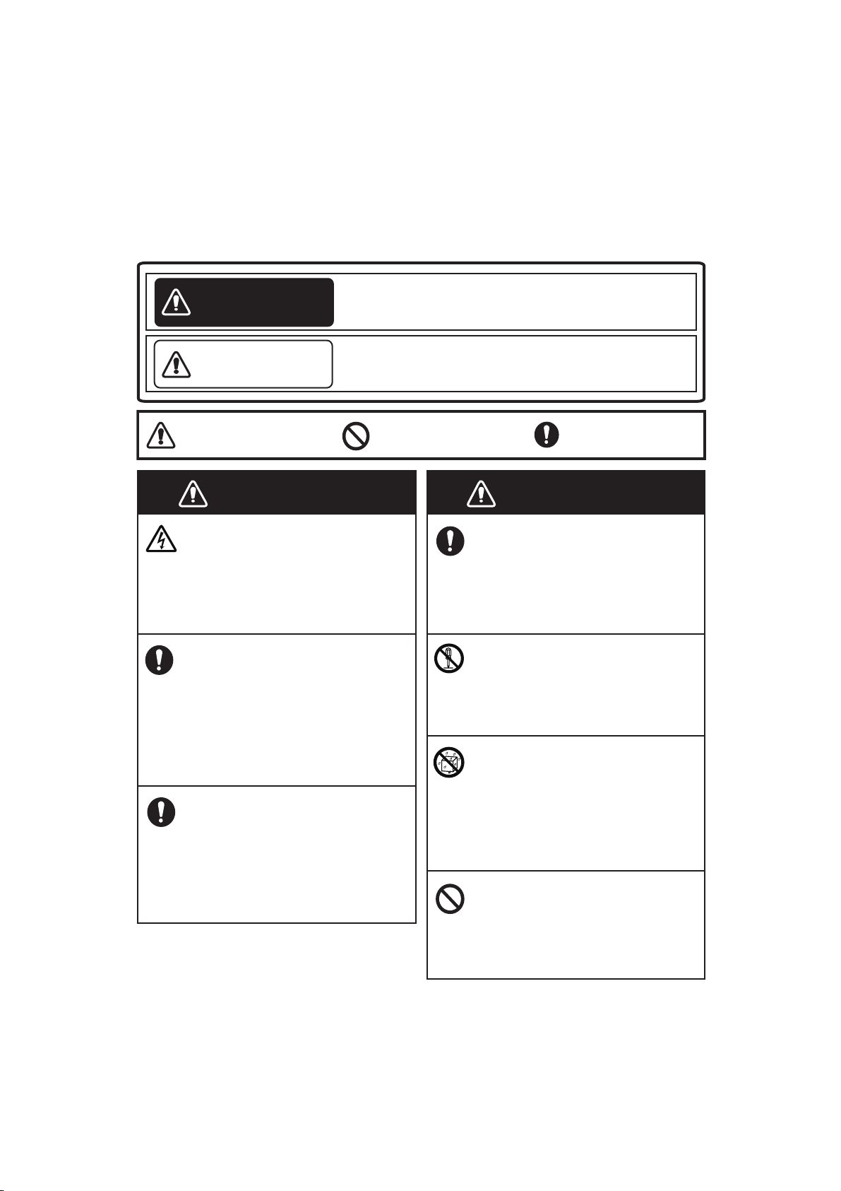
Safety instructions
WARNING
WARNING
Do not open the equipment.
The equipment uses high
voltage that can cause electrical shock. Refer any repair
work to a qualified technician.
If water leaks into the equipment or something is
dropped into the equipment,
immediately turn off the
power at the switchboard.
Fire or electrical shock can
result.
If the equipment is giving off
smoke or fire, immediately
turn off the power at the
switchboard.
Fire or electrical shock can
result.
Indicates a condition that can cause death or
serious injury if not avoided.
Indicates a condition that can cause minor or
moderate injury if not avoided.
WARNING
WARNING
If you feel the equipment is
acting abnormally or giving
off strange noises, immediately turn off the power at the
switchboard and contact a
FURUNO service technician.
Do not disassemble or modify
the equipment.
Fire, electrical shock or serious
injury can result.
Make sure no rain or water
splash leaks into the equipment.
Fire or electrical shock can
result if water leaks into the
equipment.
Do not operate the equipment
in an explosive environment.
Fire or electrical shock can
result.
WARNING
CAUTION
Warning, Caution Prohibitive Action Mandatory Action
Read these safety instructions before you operate the equipment.
iii
Page 6
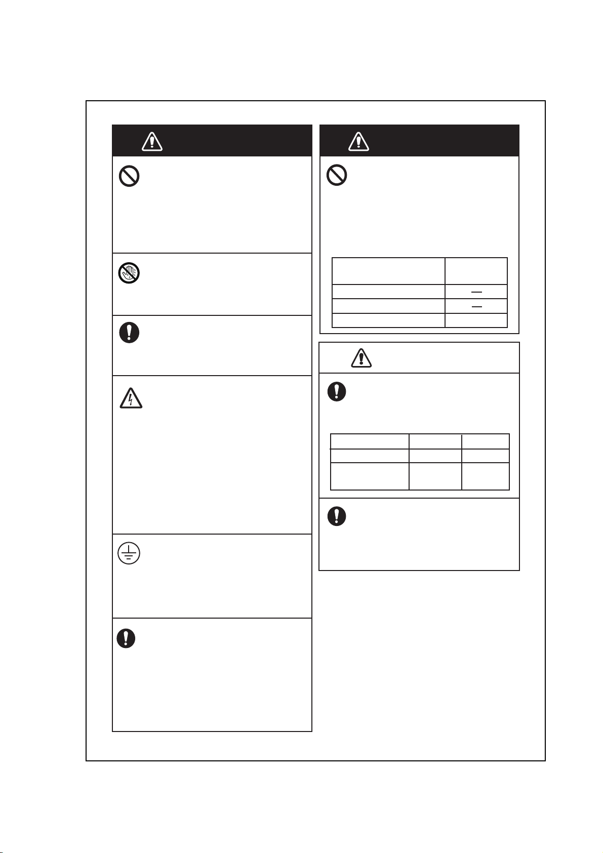
WARNING WARNING
Distance
50W/m
2
30 m
Do not place liquid-filled
containers on or near the
equipment.
Fire or electrical shock can
result if a liquid spills into the
equipment.
Do not operate the equipment
with wet hands.
Electrical shock can result.
Use the proper fuse.
Use of the wrong fuse can
cause fire or electrical shock.
Turn off the power at the
mains switchboard before
beginning the installation.
Post a sign near the switch to
indicate it should not be
turned on while the equipment is being installed.
Fire, electrical shock or serious
injury can result if the power is
left on or is applied while the
equipment is being installed.
Ensure the unit is properly
grounded.
Improper grounding can cause
electrical shock or interference
from/with other devices.
Use equipment with a suitable voltage rating for ship’s
mains.
Rated voltage is directed at
each unit, and out of range
voltage may cause damage to
the equipment.
Do not approach the FV-110
antenna unit when it is transmitting.
The radome emits radio waves
that can be harmful to the human
body, particularly the eyes.
RF power density on
antenna aperture
100W/m
2
10W/m
2
Observe the compass safety
distances shown in the table
to prevent interference to a
magnetic compass.
CAUTIOCAUTION
Antenna Unit
Antenna
Control Unit
1.00 m
0.30 m
Unit
Standard
Do not manually turn the
polarisation unit of the
antenna.
The antenna can be damaged.
VSAT restrictions
There are restrictions in use of the
frequency band 13.75 to 14 GHz in
the following countries:
Belgium, Hungary, Latvia, Malta,
Slovakia
Connect the VSAT modem provider
for local setups.
Steering
1.70 m
0.30 m
iv
Page 7

Table of Contents
Foreword................................................................................................................................xi
System configuration............................................................................................................xii
Equipment list......................................................................................................................xiii
Chapter 1 Introduction
1.1 FV-110 system ....................................................................................... 1-1
1.1.1 Above Deck Unit (ADU) ......................................................................1-2
1.1.2 Antenna Control Unit (ACU) ............................................................... 1-5
1.1.3 VSAT Modem Unit (VMU) ................................................................. 1-7
1.1.4 Satellite type approvals .........................................................................1-7
1.1.5 Service activation ................................................................................. 1-7
1.2 Part numbers and options .................................................................... 1-8
1.2.1 Applicable FURUNO model and part numbers ................................... 1-8
1.2.2 Options for FV-110 .............................................................................. 1-8
Chapter 2 Installation
2.1 Unpacking .............................................................................................. 2-1
2.1.1 What’s in the box .................................................................................. 2-1
2.1.2 Initial inspection ................................................................................... 2-2
2.1.3 Tools needed ......................................................................................... 2-2
2.1.4 Transport of the antenna ....................................................................... 2-2
2.2 Site preparation .................................................................................... 2-3
2.2.1 General site considerations ...................................................................2-3
2.2.2 Obstructions (ADU shadowing) ........................................................... 2-4
2.2.3 Blocking zones – azimuth and elevation .............................................. 2-5
2.2.4 Safe access to the ADU: Radiation hazard ........................................... 2-6
2.2.5 Ship motion and offset from the ship’s motion centre ......................... 2-7
2.2.6 ADU mast design: Foundation and height ...........................................2-8
2.2.7 Interference ......................................................................................... 2-13
2.2.8 Other precautions ................................................................................2-17
2.3 Installation of the ADU ...................................................................... 2-18
2.3.1 To install the ADU ............................................................................. 2-19
2.3.2 To open and remove the service hatch ............................................... 2-23
2.3.3 To ground the ADU ............................................................................ 2-24
2.3.4 Alternative ADU cable ....................................................................... 2-25
v
Page 8

Table of Contents
2.4 Installation of the ACU .......................................................................2-26
2.4.1 To install the ACU ..............................................................................2-26
2.4.2 To ground the ACU ............................................................................2-27
2.5 Installation of the VMU ......................................................................2-27
2.5.1 General mounting considerations — VMU ........................................2-27
2.6 To install the dual-antenna mode (optional) ....................................2-28
Chapter 3 Interfaces
3.1 Interfaces of the FV-110 ACU .............................................................3-1
3.1.1 LEDs, display and keypad .................................................................... 3-1
3.1.2 ACU connector panel — overview .......................................................3-1
3.1.3 ADU connector .....................................................................................3-2
3.1.4 Rx/Tx connectors for VMU .............................................................3-2
3.1.5 NMEA 0183 connector .........................................................................3-3
3.1.6 RS-232 and RS-422 connectors ............................................................ 3-4
3.1.7 LAN1, LAN2, LAN3 and LAN4 connectors .......................................3-5
3.2 Interfaces of the VMU ..........................................................................3-5
Chapter 4 Connecting power
4.1 Power up ................................................................................................4-1
4.1.1 Procedure ..............................................................................................4-1
4.1.2 Initialisation steps in daily use ..............................................................4-2
4.1.3 FV-110 operational ...............................................................................4-2
Chapter 5 Configuration
5.1 Introduction to the built-in web interface .......................................... 5-1
5.1.1 Overview ...............................................................................................5-1
5.1.2 Connecting to the web interface ...........................................................5-1
5.2 Calibration .............................................................................................5-3
5.2.1 Heading mode and position mode ........................................................ 5-3
5.2.2 Azimuth calibration ..............................................................................5-7
5.2.3 To set up a service profile for calibration .............................................5-9
5.2.4 Cable calibration .................................................................................5-11
5.2.5 Operation in gyro-free mode ...............................................................5-11
5.2.6 Flow chart for calibration (user controlled).........................................5-13
5.2.7 To make a line up procedure ...............................................................5-14
5.2.8 Fixed TX gain principle ......................................................................5-15
vi
Page 9

Table of Contents
5.3 Configuration with the web interface ............................................... 5-16
5.3.1 Overview and dashboard .................................................................... 5-16
5.3.2 Modem profiles and satellite profiles ................................................. 5-22
5.3.3 To set up blocking zones (RX and TX) .............................................. 5-27
5.3.4 To configure the LAN network .......................................................... 5-29
5.3.5 E-mail setup ........................................................................................ 5-31
5.3.6 Reports, syslog and SNMP traps ........................................................ 5-32
5.3.7 Dual antenna mode (optional) ............................................................ 5-36
5.3.8 Upload of new software ......................................................................5-40
5.3.9 Administration .................................................................................... 5-40
5.4 Keypad and menus of the ACU ......................................................... 5-46
5.4.1 ACU display and keypad .................................................................... 5-46
5.4.2 Navigating the menus ......................................................................... 5-47
5.4.3 The menu tree ..................................................................................... 5-48
5.4.4 Adjusting brightness of the display .................................................... 5-51
5.4.5 Power cycle of the ACU and ADU .................................................... 5-52
5.5 SNMP support ..................................................................................... 5-53
Chapter 6 Installation check
6.1 Installation check list: Antenna ........................................................... 6-1
6.2 Installation check list: ACU, connectors and wiring ......................... 6-3
6.3 Installation check list: Functional test in harbor ...............................6-5
Chapter 7 Service
7.1 Getting support: Helpdesk ................................................................... 7-1
7.1.1 Help desk and diagnostic report ...........................................................7-1
7.2 Software update .................................................................................... 7-4
7.2.1 Hardware and software requirements ................................................... 7-4
7.2.2 Software update (ADU and ACU) ........................................................ 7-4
7.2.3 To verify the software update ............................................................... 7-6
7.3 Status signalling with LEDs and status messages .............................. 7-7
7.3.1 LEDs of the ADU modules .................................................................. 7-7
7.3.2 LEDs in the ACU ................................................................................. 7-8
7.4 Removal and replacement of the ACU ............................................... 7-8
7.5 Removal and replacement of ADU modules ...................................... 7-9
7.6 Troubleshooting .................................................................................. 7-12
7.6.1 Overview ............................................................................................ 7-12
7.6.2 Event list for troubleshooting ............................................................. 7-12
7.6.3 Diagnostics report for troubleshooting ............................................... 7-12
7.7 Returning units for repair ................................................................. 7-12
vii
Page 10

Table of Contents
Appendix A Data sheets
A.1 VSAT LNB Data Sheet (physical LNB) .............................................A-1
A.1.1 VSAT LNB user installation and configuration information ..............A-2
A.2 VSAT 8 W BUC Data Sheet (Extended) .......................................... A-3
Appendix B VMU cables
B.1 Modem Cable COMTECH Serial & RSSI TT7016A ....................... B-2
B.2 Modem Cable iNFINITI iDirect VSAT modem ................................ B-3
Appendix C VMU settings
C.1 Performance optimization for blockage ............................................. C-1
C.1.1 Performance of VSAT systems encountering blockage,
configured with multiple satellites. ...................................................... C-1
C.2 OpenAMIP setup for iDirect iNFINITI & Evolution ....................... C-3
C.2.1 Protocol and interfaces ......................................................................... C-3
C.2.2 Sample options file .............................................................................. C-6
C.2.3 Configuration example (OpenAMIP) ..................................................C-9
C.2.4 Troubleshooting ................................................................................. C-10
C.3 Serial setup for iDirect iNFINITI & Evolution ............................... C-13
C.3.1 Protocol and interfaces ....................................................................... C-13
C.3.2 Console port settings ..........................................................................C-13
C.3.3 Configuration example (Serial) ......................................................... C-15
C.4 COMTECH 570L and ROSS box ..................................................... C-17
C.4.1 Protocols and interfaces ..................................................................... C-17
C.4.2 Configuration example (COMTECH 570L and ROSS) ....................C-18
C.5 COMTECH 570L ............................................................................... C-19
C.5.1 Protocol and interfaces ....................................................................... C-19
C.5.2 Configuration example (COMTECH 570L) ...................................... C-21
C.6 STM SatLink 2900 VSAT modem .................................................... C-22
C.6.1 Interfaces and VSAT modem configuration ......................................C-22
C.6.2 ACU configuration ............................................................................ C-24
C.6.3 Configuration example (STM Satlink 2900) ..................................... C-25
C.7 Gilat SkyEdge II VSAT modem ....................................................... C-26
C.7.1 Interfaces and VSAT modem configuration ......................................C-26
C.7.2 ACU configuration ............................................................................ C-27
C.7.3 Configuration example (Gilat SkyEdge II) ........................................ C-28
viii
Page 11

C.8 Inmarsat G5 modem .......................................................................... C-29
C.8.1 Interfaces and VSAT modem configuration ...................................... C-29
C.8.2 Connecting a Inmarsat G5 modem .................................................... C-29
C.8.3 Inmarsat G5 Driver ............................................................................ C-29
C.8.4 ACU configuration ............................................................................ C-30
C.8.5 Configuration example (Inmarsat G5) ............................................... C-31
C.8.6 LAN setup requirements for G5 system ............................................ C-31
C.9 Linkway S2 modem ........................................................................... C-32
C.9.1 Protocols and interfaces ..................................................................... C-32
C.9.2 ACU configuration ............................................................................ C-34
C.9.3 Configuration example (Linkway S2) ............................................... C-35
Appendix D Command line interface
D.1 Introduction ......................................................................................... D-1
D.1.1 Telnet connection ................................................................................ D-1
D.1.2 Help ..................................................................................................... D-2
D.1.3 Conventions ......................................................................................... D-2
Table of Contents
D.2 Supported commands ......................................................................... D-3
D.2.1 config ................................................................................................... D-3
D.2.2 demo .................................................................................................... D-3
D.2.3 dual_antenna ........................................................................................ D-4
D.2.4 exit ....................................................................................................... D-4
D.2.5 help ...................................................................................................... D-4
D.2.6 modem ................................................................................................. D-5
D.2.7 satellite ................................................................................................. D-5
D.2.8 status .................................................................................................... D-8
D.2.9 system .................................................................................................. D-9
D.2.10 track ..................................................................................................... D-9
D.2.11 zone .................................................................................................... D-10
Appendix E DVB-S satellites.......................................................................................E-1
Appendix F Grounding and RF protection
F.1 Why is grounding required? ................................................................F-1
F.1.1 Reasons for grounding ..........................................................................F-1
F.1.2 Safety ....................................................................................................F-1
F.1.3 ESD Protection .....................................................................................F-1
F.2 Grounding Recommendations ............................................................. F-2
F.2.1 To ground the ACU ..............................................................................F-2
F.2.2 To ground the ADU ..............................................................................F-2
F.3 Alternative grounding for steel hulls ..................................................F-3
F.3.1 To ground the ACU ................................................................................F-3
F.3.2 To ground the ADU ................................................................................F-4
ix
Page 12

Table of Contents
F.4 Alternative grounding for aluminum hulls .........................................F-5
F.4.1 To ground the ACU ..............................................................................F-5
F.4.2 To ground the ADU ..............................................................................F-5
F.5 Alternative grounding for fibre glass hulls .........................................F-6
F.5.1 To ground the ACU ..............................................................................F-6
F.5.2 To ground the ADU ..............................................................................F-6
F.6 Separate ground cable ...........................................................................F-7
F.6.1 Ground cable - construction ..................................................................F-7
F.6.2 Ground cable - connection ....................................................................F-8
F.6.3 Isolation of the ADU from the mounting base ....................................F-8
F.7 Jumper cable for grounding ...............................................................F-10
F.8 RF interference.....................................................................................F-11
F.8.1 Recommendations ...............................................................................F-11
Appendix G System messages
G.1 Event messages – overview .................................................................. G-1
G.2 List of ADU events ...............................................................................G-2
G.3 List of ACU events ...............................................................................G-8
Appendix H Approvals
H.1 Overview ...............................................................................................H-1
H.2 OEM declaration ..................................................................................H-2
H.3 CE (R&TTE) ........................................................................................H-3
H.4 Eutelsat S.A – ESV Summary Sheet .................................................. H-4
H.5 Russian Maritime Register of Shipping .............................................H-5
H.6 ANATEL Certificado de Homologação ............................................. H-8
Specifications.....................................................................................................................SP-1
Packing lists.......................................................................................................................PL-1
Outline drawings..............................................................................................................OD-1
Interconnection diagrams ................................................................................................ID-1
Index...............................................................................................................................Index-1
x
Page 13

Foreword
A word to the owner of the FV-110
Congratulations on your choice of the FURUNO FV-110. We are confident you will see why the
FURUNO name has become synonymous with quality and reliability.
Since 1948, FURUNO Electric Company has enjoyed an enviable reputation for innovative and
dependable marine electronics equipment. This dedication to excellence is furthered by our extensive
global network of agents and dealers.
Your equipment is designed and constructed to meet the rigorous demands of the marine environment.
However, no machine can perform its intended function unless properly installed and maintained.
Please carefully read and follow the operation and maintenance procedures set forth in this manual.
We would appreciate feedback from you, the end-user, about where we are achieving our purposes.
Thank you for considering and purchasing FURUNO equipment.
Features
The main features of the FV-110 are as shown below.
• Single 50 Ohm coax cable for the ADU
• Support of several VSAT modems
• Gyro-free operation
• Dual antenna mode
• SNMP support
• Remote or local simultaneous software update of ADU and ACU via PC and Internet browser
• Global RF configuration
• Full remote control and troubleshooting with built-in test equipment (BITE)
• ACU with 4 x LAN, NMEA 0183, NMEA 2000, RS-232 and RS-422
• All interfaces at the ACU, no additional units required
• AC powered.
• No scheduled maintenance
Software version
This manual is intended for FV-110 with software version 1.57.
Software information
This product includes software to be licensed under the GNU General Public License (GPL),GNU
Lesser General Public License (LGPL), BSD, Apache, MIT and others.The program(s) is/are free
software(s), and you can copy it and/or redistribute it and/or modify it under the terms of the GPL or
LGPL as published by the Free Software Foundation. Please access to the following URL if you need
source codes.
https://www.furuno.co.jp/contact/cnt_oss.html
xi
Page 14

System configuration
: Standard supply
: Optional or local supply
Antenna Unit 407009B-FUR-01
Antenna Control Unit
407016C-F19
Satellite Router
iDirectX5
Switching HUB
SRW2008
VoIP Switch
AFG200/400/800
AC Adapter
AC Adapter
AC Adapter
UPS
E11A102B001UJ/
E11A102B002UJ
100-240V AC,
1ø, 50-60Hz
Analog Telephone
Network Equipment
Gyrocompass
19” Rack Console
Equipment category
Unit Category
Antenna
Other units
Exposed to the weather
Protected from the weather
The figure below shows an example system configuration.
xii
Page 15

Equipment list
Standard supply
Name Model Code No. Qty Remarks
Antenna Unit (ADU:
Above Deck Unit)
Antenna Control Unit
(ACU)
Installation Materials CP16-04200 000-015-931 Select
407009B-FUR-01 - 1 Installation materials
407016C-F19 - 1 Installation materials
one
CP16-04120 000-015-865 40 m 8D-FB-CV cable,
CP16-04210 000-015-932 50 m 8D-FB-CV cable,
CP16-04220 000-029-109 60 m 8D-FB-CV cable,
CP16-06100 000-029-111 Select
CP16-06110 000-029-197 For 200 ACV (See PL-4.)
one
included (See PL-1.)
included (See PL-2.)
30 m 8D-FB-CV cable,
single connector
single connector
single connector
single connector
For 100 ACV (See PL-3.)
xiii
Page 16

Optional supply
UPS E11A102B001UJ - For 100/110/115/120
Dual Antenna Mode Kit 407090-010 001-423-880
Jumper Cable 407090A-925 001-423-890
Name Model Code No. Remarks
VAC
E11A102B002UJ - For 200/220/230/240
VAC
xiv
Page 17

Chapter 1
Introduction
This chapter is organised in the following sections:
• FV-110 system
• Part numbers and options
1.1 FV-110 system
The FV-110 is a unique stabilized maritime VSAT antenna system operating in the Kuband (10.7 to 14.5 GHz). It provides bi-directional IP data connections both on regional
satellite beams and quasi-global Ku-band satellite networks. The system only requires a
single 50 Ohm cable to provide the Above Deck Unit with both DC power, data and
control information. The radome does not have to be removed neither before nor after the
installation. To protect the Above Deck Unit the built-in DC motors act as brakes during
transport and when the Above Deck Unit is not powered. The ADU system can be
accessed remotely and in-depth performance analysis can be done using the built-in web
interface.
The FV-110 system consists of the following units:
1
• Above Deck Unit (ADU)
• Antenna Control Unit (ACU)
The following figure shows the FV-110 system.
Above Deck Unit (ADU)
Antenna Control Unit (ACU)
Figure 1-1: Above Deck Unit and Antenna Control Unit (ACU)
1-1
Page 18
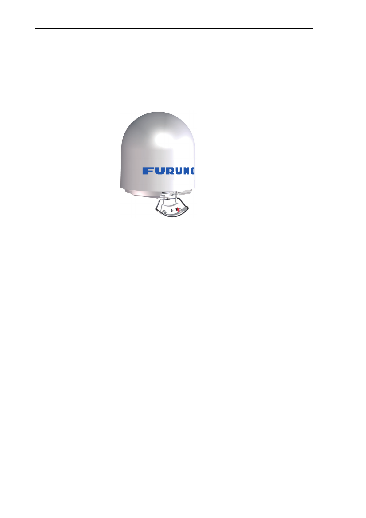
FV-110 system
1.1.1 Above Deck Unit (ADU)
The FV-110 ADU is a 103 cm VSAT stabilised tracking antenna, consisting of a
suspended antenna with a standard global RF configuration. The ADU’s weight is
126,5 kg. It is stabilized by heavy duty vibration dampers in 3-axis (plus skew) and can be
used in environments with elevations of -25° to + 125°. The ADU is powered by the ACU
and protected by a radome.
Figure 1-2: Above Deck Unit (ADU)
1-2
Page 19

Modules in the FV-110 ADU
FV-110 system
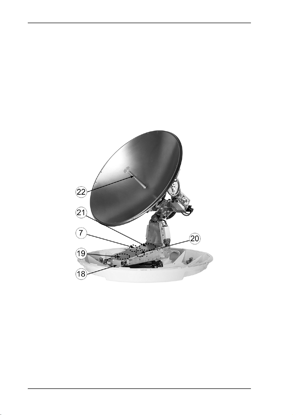
Figure 1-3: FV-110: Above Deck Unit modules 1/2
1. GNSS module.
2. VSAT Interface Module (VIM3).
3. Pedestal Control Module (PCM2).
4. Service switch.
5. Single Motor Driver Module for cross elevation (SMD (used “DDM” in log)).
6. Cross elevation motor and encoder.
7. Zero Reference Module (x4) (ZRM) (not visible on photo). (3 on this figure)
8. Single Motor Driver Module for elevation (on the bottom) (SMD (used “DDM” in
log)).
9. Elevation motor and encoder (not visible).
10.Polarisation Motor Module (PMM).
1-3
Page 20
FV-110 system
11.Polarisation motor.
12.Polarisation encoder.
13.Block Up Converter (BUC).
14.Low Noise Block downconverter (x2), (LNB).
15.Ortho Mode Transducer (OMT) (not visible on photo).
16.Inertial Sensor Module (ISM).
17.Elevation locking pin to lock the antenna dish in a fixed position.
In switch-off position the Single Motor Driver modules (SMD (used “DDM” in log))
and the BUC are turned off for safe conditions during service and repair. The switch
must be in on position for normal ADU operation.
1-4
Figure 1-4: FV-110: Above Deck Unit modules 2/2
18.Single Motor Driver Module for Azimuth (SDM (used “DDM” in log)).
19.Azimuth motor.
20.Azimuth encoder.
21.Rotary joint.
22.Feed horn.
Page 21

FV-110 ADU interface
All communication between the ADU and the ACU passes through a single standard
50 Ohm cable (with N connector) through the rotary joint. No cable work is required
inside the radome.
Installation friendly
Four lifting brackets (included in the delivery) and reuse of packing material help getting
the ADU safely into place. Satellite profile parameters are entered using the built-in web
server of the ACU, using a PC.
Service friendly
The system configuration is saved in two modules, there is no loss of data at repair. The
large service hatch of the radome gives easy access to the ADU on site. The service
switch in the ADU stops the DC Motor Driver modules and turns the BUC off. The
service tools for replacing modules are placed on a tool holder inside the radome.
All modules have a service and power LED status indicator. Each module is encapsulated
in a metal box with self-contained mounting bolts.
FV-110 system
If necessary, belts and modules can be exchanged through the service hatch on site.
You can do remote diagnostics and service with the ADU. Its built-in test equipment
checks constantly the ADU’s modules for proper functioning, it monitors and logs
information for all modules. The ADU performs a POST (Power On Self Test) and you
can request a self test (PAST, Person Activated Self Test) and Continuous Monitoring
(CM). Error codes can be read out in the web interface and in the display of the ACU.
ADU software is updated automatically when making a software update of the ACU.
1.1.2 Antenna Control Unit (ACU)
The ACU is the central unit in the system. It contains all user interfaces and manages all
communication between the ADU and the connected VMU, a connected PC and an
optional FleetBroadband service communication line. The ACU has a display, status
LEDs and a keypad. It provides a DHCP client. During configuration you can configure
heading offset, save satellite and VMU setups and enter No Transmit Zones (blocking
zones in which the ADU does not transmit).
The ACU provides DC power to the ADU through a single coaxial cable.
1-5
Page 22

FV-110 system
LAN3 (Service)
to front
NMEA
RS-232
RS-422
Ground
RX Out
TX In
LAN1 to 4
LAN1, 2: Modem Control
AC power
Fuse 7AT/SB
Antenna
ACU interfaces
The ACU has the following interfaces and switch:
• N-connector for ADU cable (50 Ohm).
• 2 x F connectors for Rx and Tx cables (75 Ohm) to VSAT modem.
• Multi connector for NMEA interfaces (for input from GPS compass or Gyro compass).
• RS-422 interface for modem control.
Figure 1-5: FV-110 ACU, connector overview
• RS-232 interface for modem control.
• 4 x LAN ports for VSAT modem control and user equipment.
• AC input.
• On/Off power switch
The ACU has additionally a LAN connector at the front for accessing the service port
from the ACU front panel.
Installation friendly
The ACU comes in a 19” rack version.
Service friendly
You can do remote diagnostics and service with the ACU. Its built-in test equipment
checks constantly the device for proper functioning. It performs POST (Power On Self
Test) and you can request a PAST (Person Activated Self Test). Continuous Monitoring
(CM) is also available. BITE error codes can be read out in the web interface and in the
display of the ACU.
Service port
Figure 1-6: FV-110 ACU, 19” rack version
1-6
Software update is done via a connected PC and the built-in web interface of the ACU.
Page 23

1.1.3 VSAT Modem Unit (VMU)
FV-110 is designed to be operated with third-party VSAT modems. For a list of supported
VSAT modems see SP-2.
1.1.4 Satellite type approvals
For a list of satellite type approvals see Eutelsat S.A – ESV Summary Sheet on page H-4,
Russian Maritime Register of Shipping on page H-5, and ANATEL Certificado de
Homologação on page H-8.
1.1.5 Service activation
Before you can start using the FV-110, you need to activate the system for VSAT service.
Contact your service provider for activation.
FV-110 system
1-7
Page 24
Part numbers and options
1.2 Part numbers and options
1.2.1 Applicable FURUNO model and part numbers
The following model and part numbers are available for the FV-110 system:
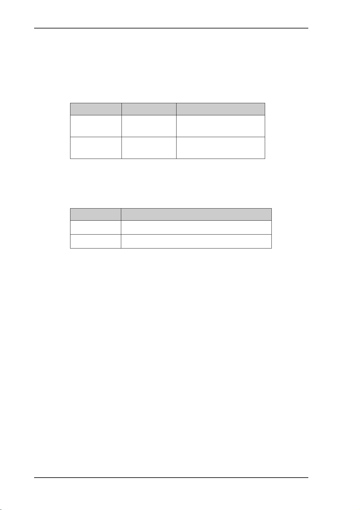
Part number Model number Description
407009B-27001 407009B-FUR-01 FV-110 Above Deck Unit
(ADU) Variant B
407016C-27000 407016C-F19 FV-110 Antenna Control Unit
(19 inch rack)
Table 1-1: Model and part numbers for the FV-110 system
1.2.2 Options for FV-110
The following options are available for the FV-110 system:
Part number Description
407090A-925 Pigtail Cable 1.25 m, N-Conn, female/male
407090-010 Accessory kit for dual antenna mode
Table 1-2: Model and part numbers for options of the FV-110 system
1-8
Page 25

Chapter 2
Installation
This chapter is organised in the following sections:
• Unpacking
• Site preparation
• Installation of the ADU
• Installation of the ACU
• Installation of the VMU
2.1 Unpacking
2.1.1 What’s in the box
ADU
Unpack your FV-110 ADU and check that the following items are present:
• ADU with 4 lifting brackets (already mounted)
2
ACU
• Package with bolts, washers and cable glands (2 sizes)
Unpack your FV-110 ACU and check that the following items are present:
• 1 x Ethernet cable (2 m)
• 1 x Ethernet cable (short)
• Power cable (230 VAC)
• 2 x 75 Ohm coax cables F-F (1m), for Rx and Tx
• NMEA multi-connector
• Installation manual
2-1
Page 26
Unpacking
2.1.2 Initial inspection
Inspect the shipping cartons and wooden box immediately upon receipt for evidence of
damage during transport. If the shipping material is severely damaged or water stained,
request that the carrier's agent be present when opening the cartons and wooden box. Save
all box packing material for future use.
WARNING! To avoid electric shock, do not apply
power to the system if there is any sign of shipping
damage to any part of the front or rear panel or the outer
cover. Read the safety summary at the front of this
manual before installing or operating the system.
After unpacking the system, i.e. removing the top and sides of the wooden box and
opening the cartons, inspect it thoroughly for hidden damage and loose components or
fittings. If the contents are incomplete, if there is mechanical damage or defect, or if the
system does not work properly, notify your dealer.
2.1.3 Tools needed
• Unbraco key (4 mm), included, mounted on a tool holder inside the radome.
Other tools that may be needed during the installation:
• Torx TX 20 to open the locks of the service hatch
• Wrench to fasten the mounting bolts for the ADU
• Wrench to fasten the N connector at the ADU
• PC and Internet browser
• Crimping tools
2.1.4 Transport of the antenna
During transport the antenna must be able to move freely inside the radome. You must
follow the instructions below to keep a valid warranty:
CAUTION!
Do not lock the antenna dish with the elevation
locking pin during transport.
Do not strap parts of the antenna.
2-2
These actions might cause damage to the antenna.
Damage due to actions listed above will void the
warranty.
Page 27

2.2 Site preparation
The following topics have to be considered when installing the ADU:
• General site considerations
• Obstructions (ADU shadowing)
• Blocking zones – azimuth and elevation
• Safe access to the ADU: Radiation hazard
• Ship motion and offset from the ship’s motion centre
• ADU mast design: Foundation and height
• Interference
• Other precautions
2.2.1 General site considerations
For optimum system performance, some guidelines on where to install or mount the
different components of the FV-110 System must be followed.
Site preparation
It is recommended to mount the ADU in a location with as much 360° free line of sight to
the satellite as possible while making sure that the support structure fulfills the
requirements for the mast foundation. The ADU must be mounted on stiffened structures
with a minimum of exposure to vibrations.
2-3
Page 28

Site preparation
Note
2.2.2 Obstructions (ADU shadowing)
Place the ADU so that it has as much free line-of-sight as possible without any structures
in the beam through one full 360 degrees turn of the vessel. Do not place the ADU close
to large objects that may block the signal. To avoid obstruction elevate the ADU by
mounting it on a mast or on a mounting pedestal on a deck or deck house top.
Figure 2-1: Signal degradation because of obstructing objects
The ADU is stabilized in 3-axis (plus skew) and can be used in environments with
elevations of -25° to + 125° to allow for continuous pointing even in heavy sea
conditions.
The ADU beam is approximately 1 m in diameter for the first 30 m from the ADU.
Beyond 30 m the beam gradually widens so that it is approximately 5 m in diameter at
100 m distance. This beam expansion continues with increasing distance.
Any obstructions, such as masts, funnels, bridge house etc. within this field can cause
signal degradation or signal loss.
Please note that due to the short wavelength at Ku band and
the narrow beam width of the ADU even a 6 mm steel wire
placed within 50 m inside the beam can causes signal
degradation.
2-4
Page 29
2.2.3 Blocking zones – azimuth and elevation
$QWHQQD
2EVWUXF
WLRQ
$]LPXWK
$]LPXWK
$]LPXWK
$]LPXWK
%ORFNLQJ]RQH
$]LPXWK$]LPXWK
(OHYDWLRQWR
%ORFNLQJ]RQH
$]LPXWK$]LPXWK
(OHYDWLRQWR
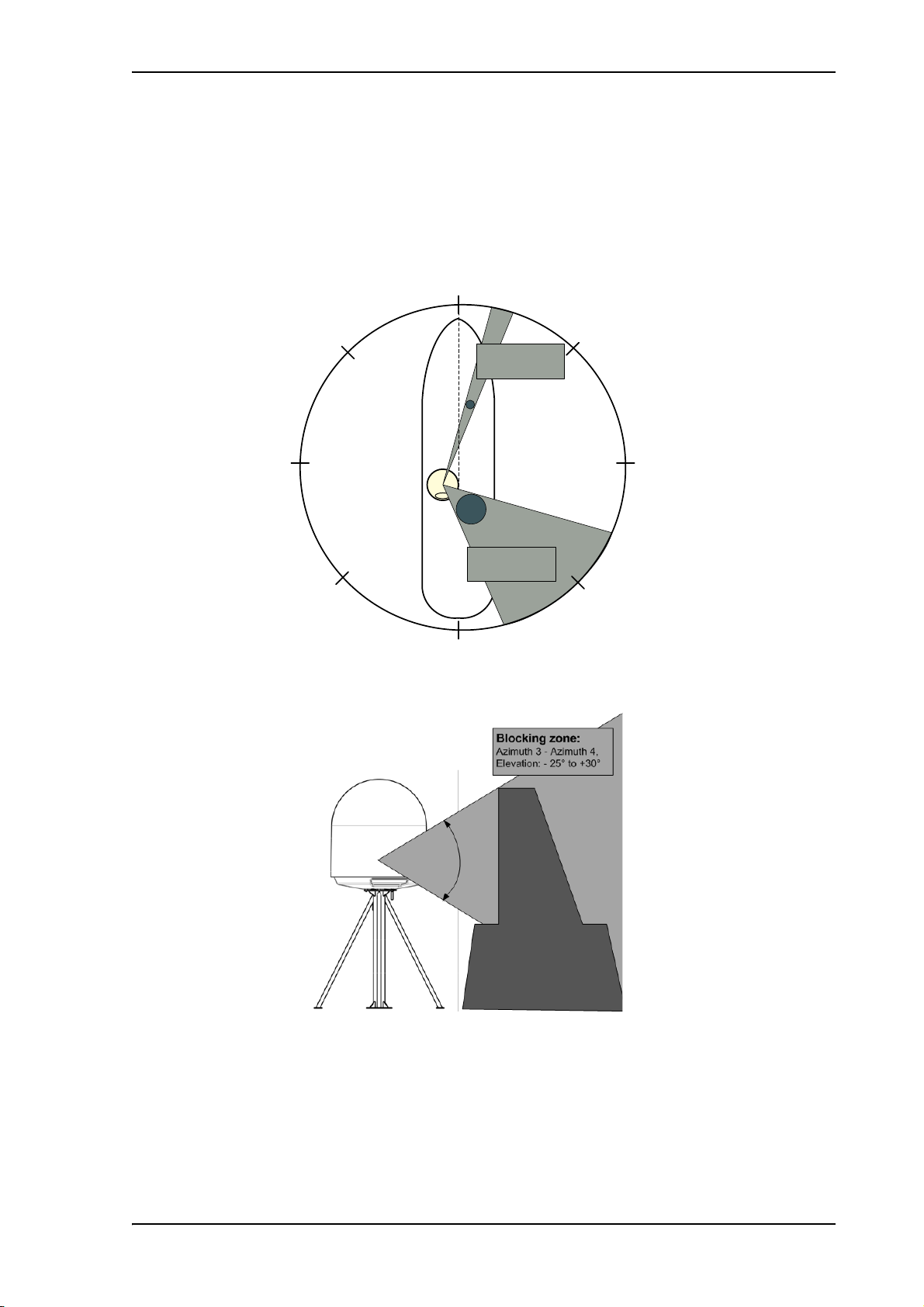
Your installation may require that you set up blocking zones for the ADU, i.e. areas where
the ADU will not transmit and areas where transmit power is potentially dangerous for
persons frequently being in these zones. You can set up 8 blocking zones. Each blocking
zone is set up with azimuth start and stop, and elevation angle.
Site preparation
Figure 2-2: 2 blocking zones with no-transmit zones, azimuth (example)
Figure 2-3: Blocking zone with no-transmit zones, elevation angle (example)
The blocking zones are set up in the built-in web interface of the ACU. For further
information see To set up blocking zones (RX and TX) on page 5-27.
2-5
Page 30
Site preparation
MICROWAVE RADIATION
NO PERSONNEL within safety
distance of 30 m, based on 10 W/m
2
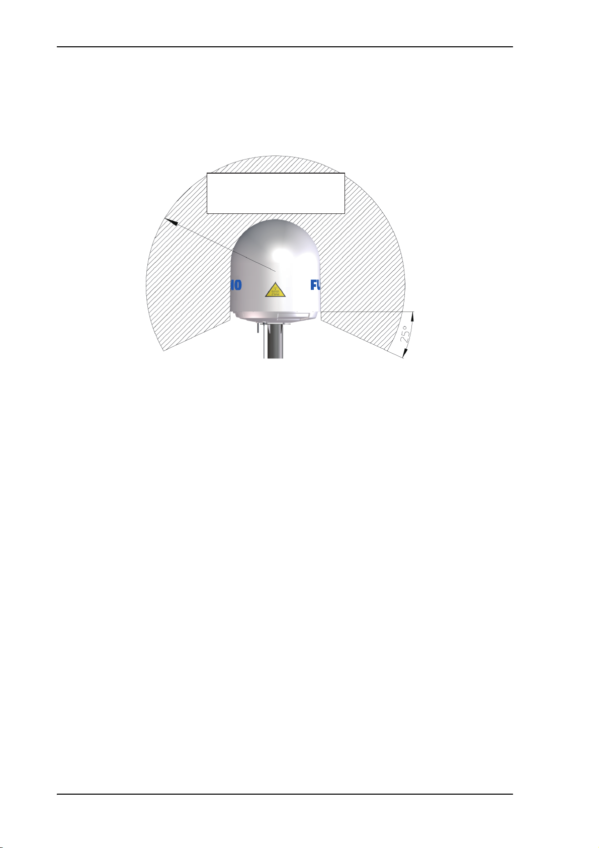
2.2.4 Safe access to the ADU: Radiation hazard
The FV-110 ADU radiates up to 49 dBW EIRP. This translates to a minimum safety
distance of 30 m from the ADU while it is transmitting, based on a radiation level of
10 W/m
2
.
Figure 2-4: FV-110: Radiation hazard, safety distance 30 m
2-6
Page 31

2.2.5 Ship motion and offset from the ship’s motion centre
KPD[
Even though it is recommended to mount the ADU high, keep the distance between the
ADU and the ship’s motion centre as short as possible. The higher up the ADU is
mounted, the higher is the linear g force applied to the ADU. The g force also depends on
the roll period of the ship, see Table 2-1. If the g force applied is too high, performance
and ADU signal stabilization may be reduced and eventually the ADU may be damaged.
Refer to the following table for allowed mounting heights above the ship’s motion centre.
Site preparation
Figure 2-5: Maximum distance from the ship’s motion centre (h max)
Max. ADU mounting height (h max)
Min.
roll period
Full
performance
Potential risk of damage
4s 12m 16m
6s 27m 35m
8s 48m 62m
10 s 75 m 98 m
Table 2-1: Maximum distance from the ship’s motion center versus
ship’s roll period
2-7
Page 32

Site preparation
Gusset plates
(15 mm thick)
15 mm
2.2.6 ADU mast design: Foundation and height
The ADU mast must be designed to carry the weight of the ADU unit, which is 126,5 kg
(FV-110). The mast must also be able to withstand on-board vibrations and wind speeds
up to 110 knots on the radome, even in icing conditions.
ADU mast flange
Fit the top of the ADU mast with a flange with clearance holes matching the bushings in
the radome and with minimum 4 gusset plates. No center hole is necessary in the flange.
• Flange thickness: Minimum 15 mm.
• 4 gusset plates: Minimum 15 mm thick, must be placed close to the holes in the
mounting plate and evenly distributed.
Figure 2-6: FV-110: ADU mast flange, top and side view
Recommended flatness on the mast mount plateau is below 3,0 mm.
Figure 2-7: ADU mast flange, recommended flatness on the mast mount
plateau
2-8
Page 33

Site preparation
50
Welded seam
Welded seam
Gusset plate
Allow sufficient space so the
nut is free of the welded seam
and there is room for tools
(min. 50 mm).
Clearance hole
for M12 bolts
Figure 2-8:
ADU mast flange, distance to the welded seam
CAUTION! Avoid sharp edges where the flange is in
direct contact with the radome. Round all edges as much as
possible to avoid damaging the surface of the radome.
Figure 2-9: FV-110: ADU, bottom view
2-9
Page 34
Site preparation
Note
Note
Note
Mast length and diameter
The placement of the ADU must ensure a rigid structural connection to the hull or
structure of the ship. Parts of the ship with heavy resonant vibrations are not suitable
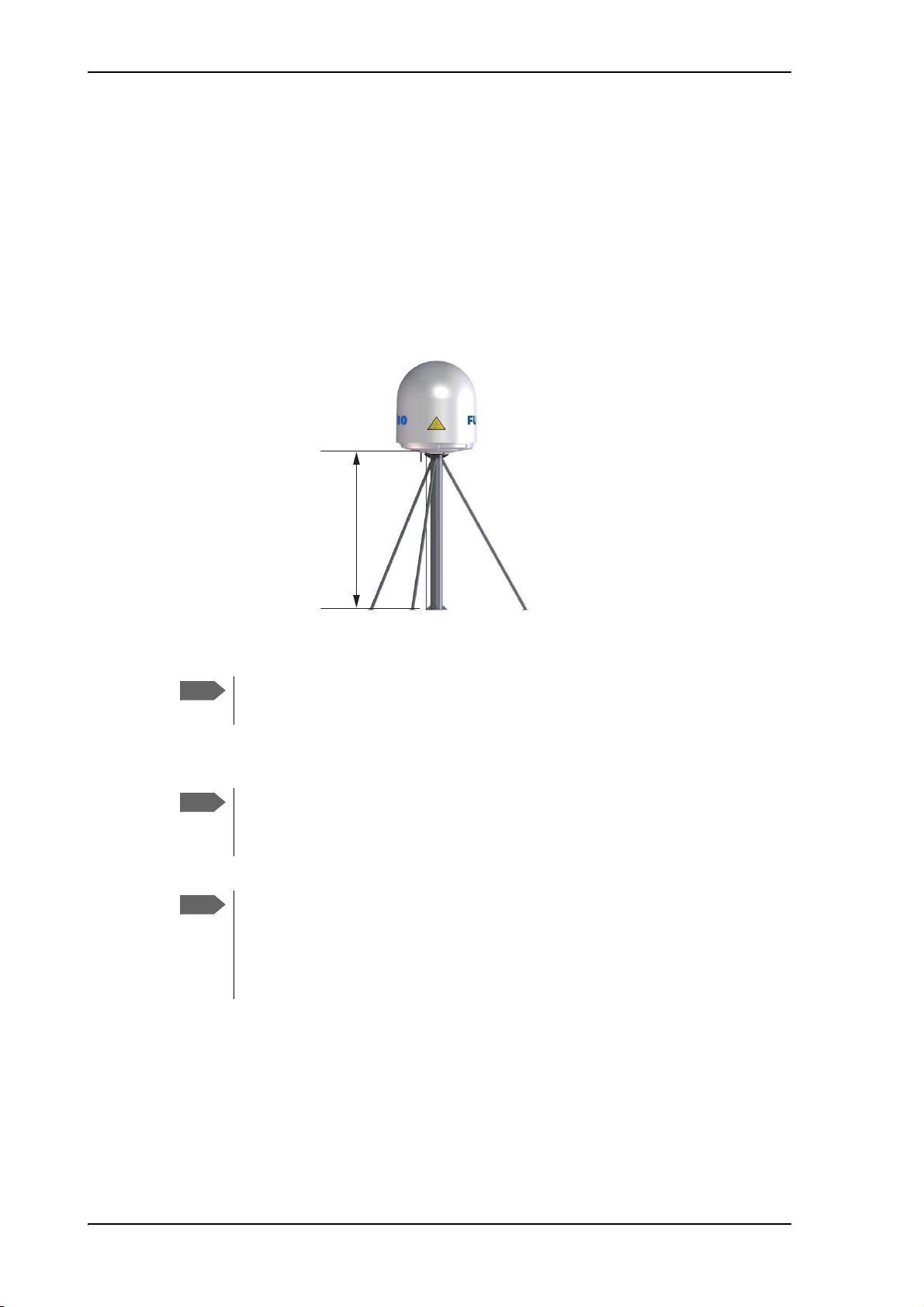
places for the ADU. A small platform or short mast shall provide rigid support for the
ADU fastening bolts and a rigid interface to the ship.
If it is necessary to use a tall mast, you must stabilise the mast with bracing. Note that the
design values given below depend on rigid ADU-ship interfaces. The cross-sectional
properties and the corresponding maximum free length give a natural frequency close to
30 Hz. It is recommended to shorten the mast length as much as possible to obtain higher
frequencies. Preferably, mount stays or wires to stabilize the mast further.
Free mast length (m)
Figure 2-10: Free mast length and bracing for a tall mast
Make sure that there is free space below the drain tube. Read
also Condensation and water intrusion on page 2-17.
The tables in the next sections give some suggested design values for the free mast length.
The tables list the values for steel masts. For aluminium
masts, the free mast length is reduced to 75% of the values
for steel.
Bracing and rigid masts can still not prevent vertical vibration
if the mast is attached to a deck plate that is not rigid. Make
every effort to mount the mast on a surface that is well
supported by ribs. If this is not possible, provide extra deck
plate propping.
2-10
Page 35
FV-110 ADU mast length
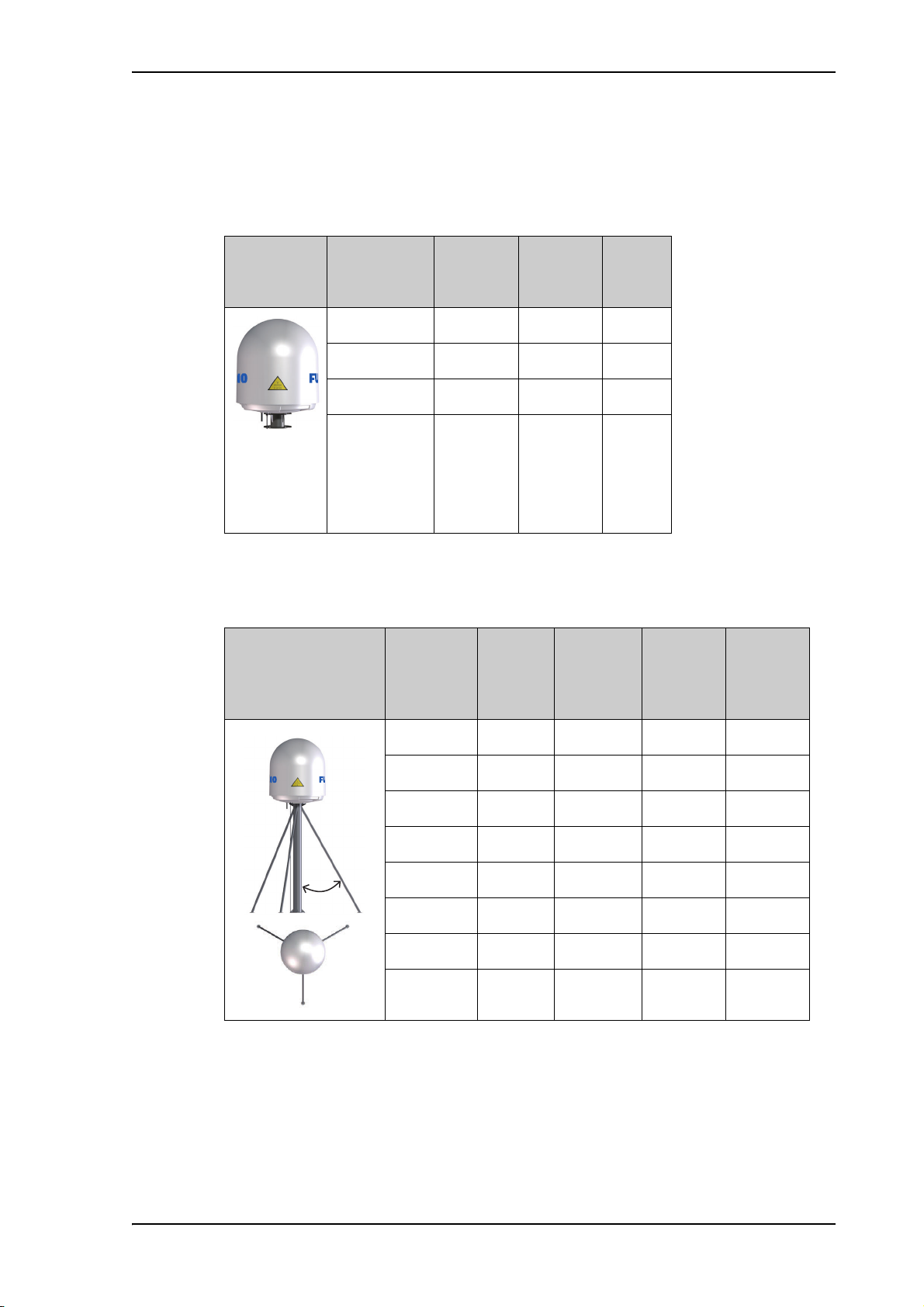
The below tables show the minimum dimensions for a FV-110 ADU mast with and
without stays or wires. Note that the values are only guidelines - always consider the
environment and characteristics of the ship before deciding on the mast dimensions.
Site preparation
Mast
without
braces
Max. free
mast length
(steel), (m)
a
0.4
Outer
Diameter
(mm)
Wall
Thickness
(mm)
200 5 24.0
Weigh t
(kg/m)
0.6 220 5 26.5
0.8 250 5 30.2
1 270 5 32.7
Table 2-2: FV-110: Mast dimensions without braces
a. The height of 0.4 m is not recommended to be used as it will
make access through the ADU’s service hatch difficult.
Mast with 3 braces
Max. free
mast length
(steel), (m)
Outer
Diameter
(mm)
Wall
Thickness
(mm)
Outer
Diameter
for brace
(mm)
Thickness
for brace
(mm)
30-40º
1.2 140 10 50 5.0
1.2 200 5 50 5.0
1.6 140 10 70 5.0
1.6 200 5 70 5.0
2 160 10 70 5.0
22205 705.0
2.5 180 10 80 5.0
2.5 220 5 80 5.0
Table 2-3: FV-110: Mast dimensions with 3 braces
2-11
Page 36
Site preparation
Mast with 2 braces
Max. free mast
length (steel),
(m)
Outer
Diameter
(mm)
Wall
Thickness
(mm)
1.2 160 10 80 5.0
1.2 200 5 80 5.0
1.6 180 10 80 5.0
1.6 220 5 80 5.0
2 180 10 80 5.0
22405805.0
2.5 200 10 80 5.0
2.5 260 5 80 5.0
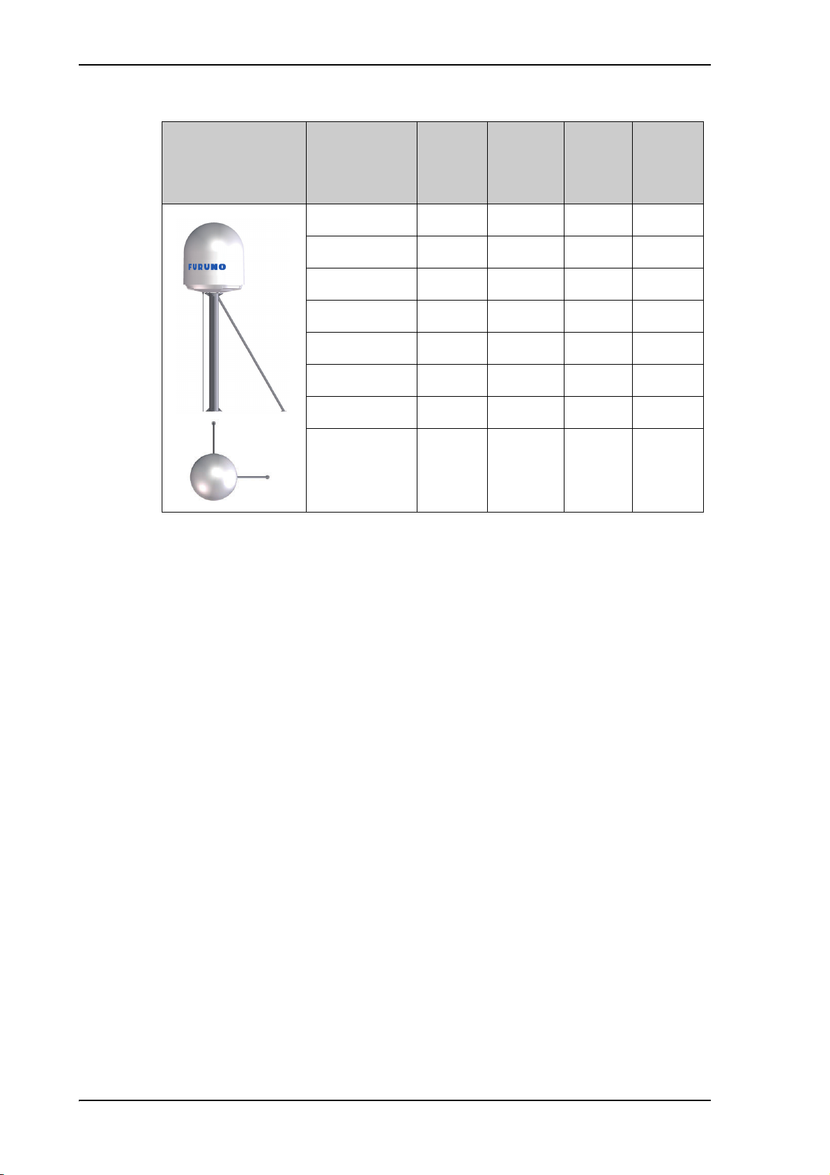
Table 2-4: FV-110: Mast dimensions with 2 braces
Outer
Diameter
for brace
(mm)
Thickness
for
brace
(mm)
2-12
Page 37

2.2.7 Interference
Note
Radar
Min. 15°
Min. 15°
Do not place the ADU close to interfering signal sources or
receivers. For allowed distances to other transmitters see
Figure 2-12: Recommended distance to transmitters (m) for
frequencies below 1000 MHz on page 2-16. We recommend
testing the total system by operating all equipment
simultaneously and verifying that there is no interference.
The ADU must be mounted as far away as possible from the ship’s radar and high power
radio transmitters, because they may compromise the ADU performance. RF emission
from radars might actually damage the ADU.
The FV-110 ADU itself may also interfere with other radio systems.
Radar
It is difficult to give exact guidelines for the minimum distance between a radar and the
ADU because radar power, radiation pattern, frequency and pulse length/shape vary from
radar to radar. Further, the ADU is typically placed in the near field of the radar ADU and
reflections from masts, decks and other items in the vicinity of the radar are different from
ship to ship.
Site preparation
However, it is possible to give a few guidelines. Since a radar radiates a fan beam with a
horizontal beam width of a few degrees and a vertical beam width of up to +/- 15°, the
worst interference can be avoided by mounting the ADU at a different level – meaning
that the ADU is installed minimum 15° above or below the radar antenna. Due to near
field effects the benefit of this vertical separation could be reduced at short distances
between radar antenna and the FV-110 ADU. Therefore it is recommended to ensure as
much vertical separation as possible when the FV-110 ADU has to be placed close to a
radar antenna.
Figure 2-11: Interference with the vessel’s radar
2-13
Page 38
Site preparation
Radar distance
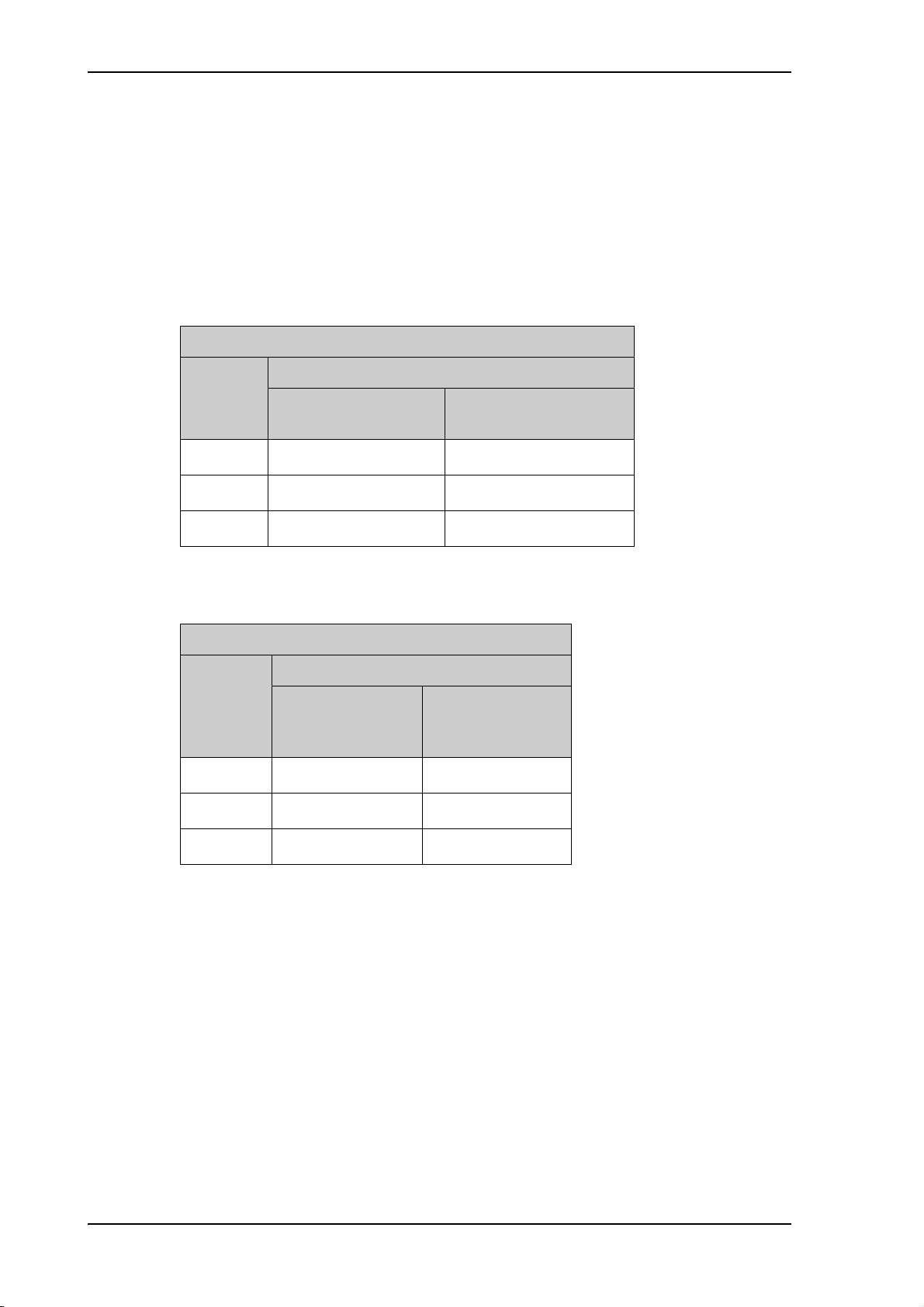
The minimum acceptable separation (d min.) between a radar and the ADU is determined
by the radar wavelength/frequency and the power emitted by the radar. The tables below
show some “rule of thumb” minimum separation distances as a function of radar power at
X and S band. If the d min. separation listed below is applied, antenna damage is normally
avoided.
“d min.” is defined as the shortest distance between the radar antenna (in any position)
and the surface of the FV-110 ADU.
0 – 10 kW 1.0 m 1.0 m
30 kW 2.0 m 1.0 m
Radar
power
X-band (~ 3 cm / 10 GHz) damage distance
FV-110 ADU
d min. at 15° vertical
separation
d min. at 60° vertical
separation
50 kW 3.3 m 1.7 m
Table 2-5: Minimum radar separation, X-band
S-band (~ 10 cm / 3 GHz) damage distance
FV-110 ADU
Radar
power
d min. at 15°
vertical
separation
d min. at 60°
vertical
separation
0 – 10 kW 2.0 m 1.0 m
30 kW 3.0 m 1.5 m
50 kW 5.0 m 2.5 m
Table 2-6: Minimum radar separation, S-band
The separation distance for C-band (4-8 GHz) radars should generally be the same as for
SX-band radars.
2-14
Page 39

Radar interference
Even at distances greater than “d min.” in the previous section the radar might still be able
to degrade the performance of the FV-110 system.
The presence of one or more S or X-band radars within a radius up to 100 m may cause a
minor degradation of the Ku-band connection. The degradation will be most significant at
high radar pulse repetition rates.
As long as receiving conditions are favourable, this limited degradation is without
importance. However, if receiving conditions are poor – e.g. due to objects blocking the
signal path, heavy rainfall or icing, low satellite elevation and violent ship movements –
the small extra degradation due to the radar(s) could cause poor connection quality.
The presence of S-band radar(s) is unlikely to cause any performance degradation – as
long as the minimum distances (d min.) listed in the previous section are applied.
It is strongly recommended that interference free operation is verified experimentally
before the installation is finalized.
Site preparation
CAUTION! The ADU must never be installed
closer to a radar than “d min.” - even if
experiments show that interference free
operation can be obtained at shorter distances
than “d min.” in the previous section.
GPS receivers
Good quality GPS receivers will work properly very close to the ADU - typically down to
one meter outside the main beam.
2-15
Page 40

Site preparation
Other transmitters
See the following figure for minimum recommended distance to transmitters in the
frequency range below 1000 MHz.
Figure 2-12: Recommended distance to transmitters (m) for frequencies
below 1000 MHz
2-16
Page 41
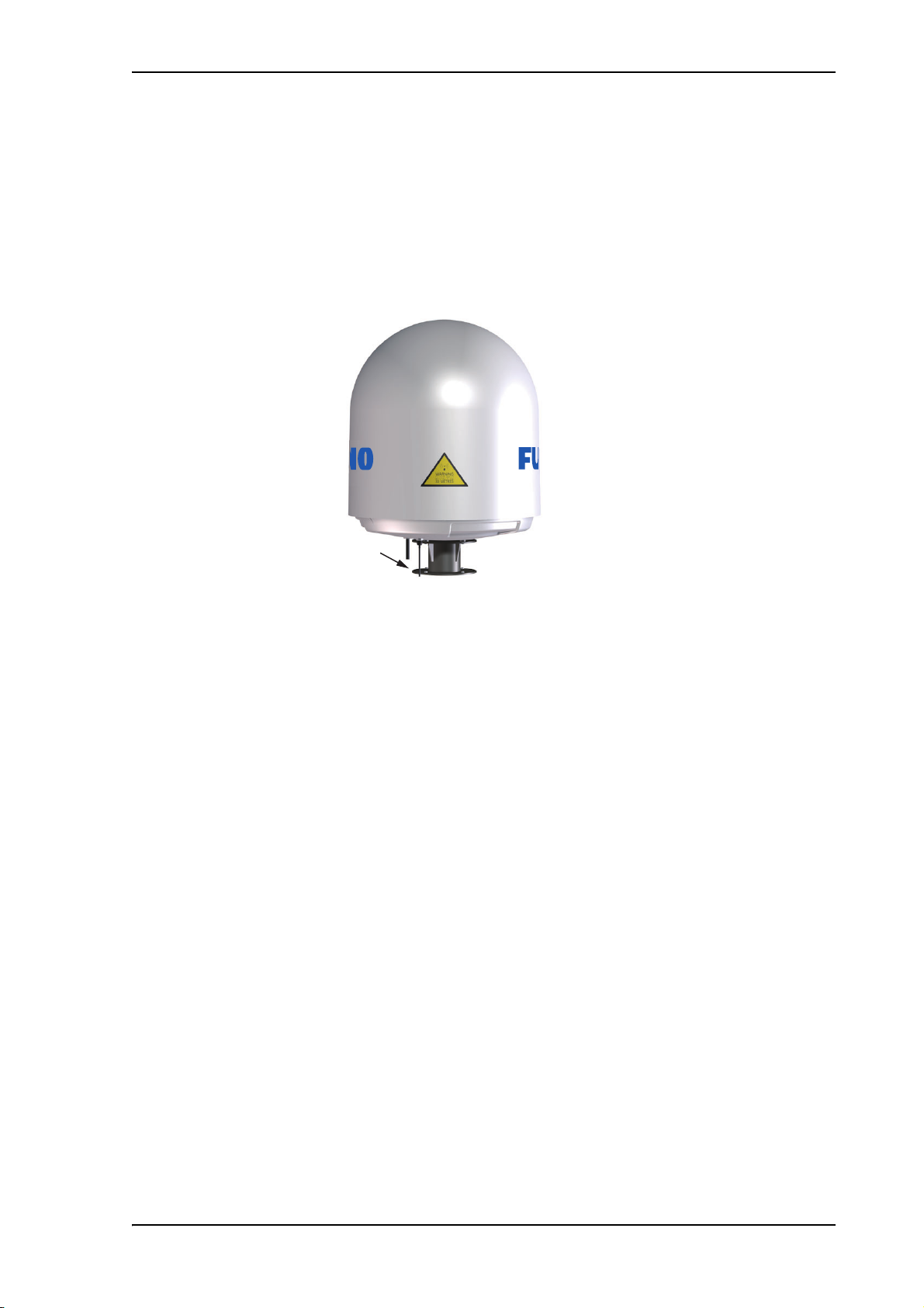
2.2.8 Other precautions
Condensation and water intrusion
If possible, install the radome such that direct spray of seawater is avoided. In some
weather conditions there may occur condensation inside the radome. The drain tube is
designed to lead any water away from inside the radome. Make sure the ADU’s drain tube
is open and that there it free space between the drain tube and the mounting surface so
water can escape and there is ventilation for the ADU.
Site preparation
Deposits
Free space
Figure 2-13: FV-110: Drain pipe with free space
It is recommended not to use pneumatic tools for cleaning the radome, especially at a
short distance and directly at the split between top and bottom.
Do not place the ADU close to a funnel, as smoke deposits are corrosive. Furthermore,
deposits on the radome can degrade performance.
2-17
Page 42

Installation of the ADU
2.3 Installation of the ADU
The ADU is shipped fully assembled. You have to install it on the mast and attach the
ADU cable.
WARNING! Use a strong webbed sling with a belt to
lift the ADU without damaging the radome. Make sure
that the sling can carry the ADU’s weight126,5 kg (FV-
110).
WARNING! The ADU may be subject to swaying
motions in windy conditions. Always use tag lines to
stabilise the ADU during hoisting.
Webbed sling with belt
Tag lines
Figure 2-14: FV-110: Use of strong sling with a belt and tag lines for safe
hoisting
Before installing the ADU read the following guidelines.
2-18
Page 43
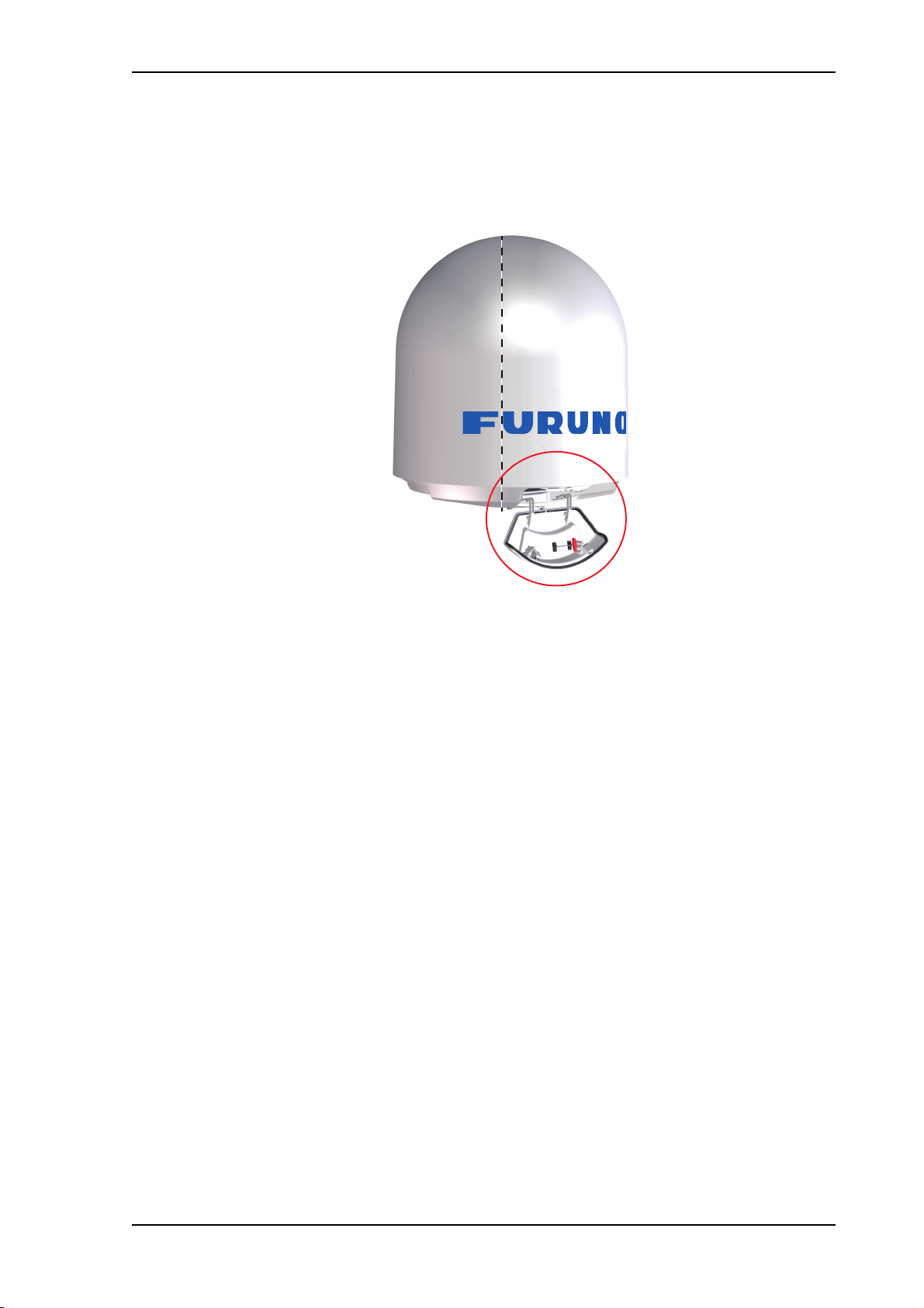
2.3.1 To install the ADU
Make sure that there is sufficient space underneath the ADU to open the service hatch.
Through this hatch you access the ADU modules for service and maintenance.
Installation of the ADU
Provide sufficient free
space for access through
the service hatch.
Figure 2-15: FV-110: Free space for access to the service hatch
The ADU does not have to be aligned with the bow-to-stern line of the ship. When
configuring the FV-110 you make an azimuth calibration to obtain the correct azimuth of
the ADU.
• It is important to maintain vertical orientation of the ADU center line.
• Consider the aspect of interference, read more about this in Interference on page 2-13.
• Install the ADU where vibrations are limited to a minimum.
• Always use all 4 bolts when installing the ADU.
To install the ADU, do as follows:
1. Install the mast with the mast flange and have the 4 M12 bolts ready.
2. Undo all shipping buckles, take off the wooden top and remove the casing.
3. Unscrew the 4 bolts holding the ADU on the wooden platform.
4. Attach a webbed, four-part sling with a belt to all 4 lifting brackets.
2-19
Page 44
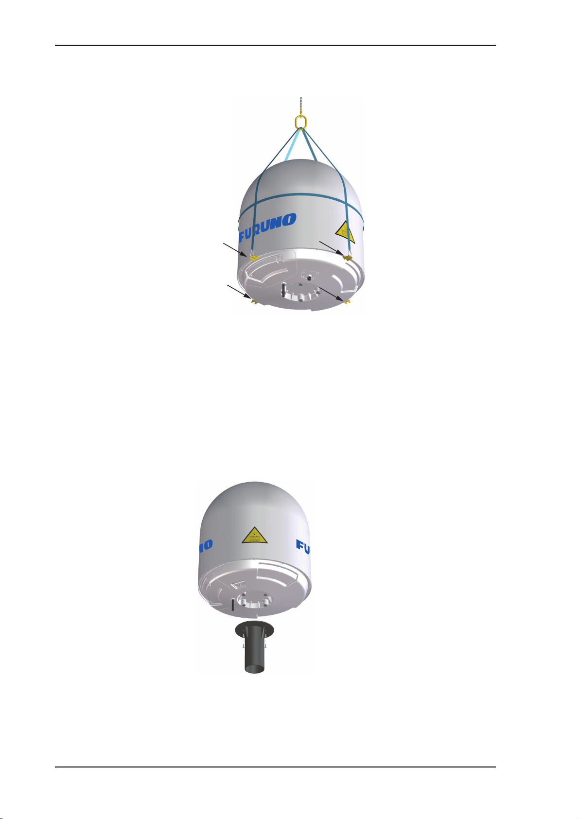
Installation of the ADU
Figure 2-16: FV-110: ADU installation, webbed sling attached to the 4 lifting
brackets
5. Attach 2 tag lines of suitable length to 2 lifting brackets and man them.
6. With a crane lift the ADU off the wooden platform and move it on top of the ADU
mast.
7. Install the ADU on the mast flange with 4 M12 bolts and washers.Read carefully and
follow instructions given in To ground the ADU on page F-2.
Tightening torque value: 30 Nm.
8. Remove the 4 lifting brackets. For safekeeping fasten the lifting brackets inside the
bottom of the radome.
2-20
Figure 2-17: Mounting the ADU on the mast flange
9. Put the coaxial ADU cable through the protection plate as shown in the following
figure (FV-110), and connect the N connector of the ADU cable to the ADU.
Page 45

Installation of the ADU
Protection plate
N connector
1
2
3
4
5
6
Select a suitable size for the cable gland: 16—20 mm diameter or 19—23 mm
diameter. See also N-connector interface on the ADU on page 2-22 for a more detailed
drawing how to connect the N-connector on the ADU.
Ensure that the connector assembly is properly protected against seawater and
corrosion. As a minimum, wrap it with self-amalgamating rubber.
10.Put the protection plate in place and fasten the 4 bolts (picture 5).
11.Fasten the nut.
Where the cables are exposed to mechanical wear — on deck, through bulkheads, etc. –
protect the cables with steel pipes. Otherwise, follow standard procedures for cabling in
ship installations.
Figure 2-18: FV-110: Connecting the ADU cable
2-21
Page 46

Installation of the ADU
N-connector interface on the ADU
Maximum allowed RF loss in the ADU cable
Maximum allowed cable loss ≤ 20 dB at 1700 MHz. This is to ensure optimum
performance of the system.
2-22
Page 47
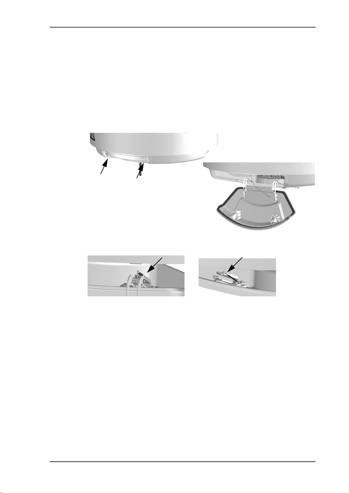
2.3.2 To open and remove the service hatch
Open with Torx TX20
Open the hatch to access the antenna modules. The two latches of the service hatch must
be locked by fastening the two screws in the latches with a Torx TX20 screw driver to
protect the ADU modules against unauthorised access.
You can remove the hatch for better mobility when servicing the antenna. Do as follows
to open and remove the service hatch:
1. With a Torx TX20 screw driver, remove the two screws locking the latches.
2. Pull open the two latches and let the lid fall open.
Installation of the ADU
Figure 2-19: FV-110: Opening the service hatch
3. Remove the 2 split pins and park them.
Figure 2-20: Removing the 2 split pins
4. Pull the service hatch free.
2-23
Page 48

Installation of the ADU
Bolt used
for best grounding
2.3.3 To ground the ADU
The ADU must be grounded using the mounting bolts. If the ADU cannot or should not be
electrically connected directly to the mounting surface, you can use a separate grounding
cable to make the connection between the ADU and the common ground to which the
ACU is also connected. If grounding to the ship ground is impossible, for example if you
have a fibre glass hull, see.Alternative grounding for fibre glass hulls on page F-6.
To obtain a good ground connection, the metal underneath the head of at least one bolt
must be clean of insulating protective coating and a serrated washer should be used. After
tightening the bolts we recommend that you seal the area suitably in order to avoid
corrosion of the grounding point. Use stainless steel bolts and washers.
Optimum grounding is achieved by connecting the ground wire to the bolt marked in the
figure below.
2-24
Figure 2-21: FV-110: ADU, bolt for optimum grounding
For further information on grounding and RF protection see Grounding and RF protection
on page F-1.
Page 49
2.3.4 Alternative ADU cable
The allowed RF loss in the antenna cable is determined by the attenuators of the PSM and
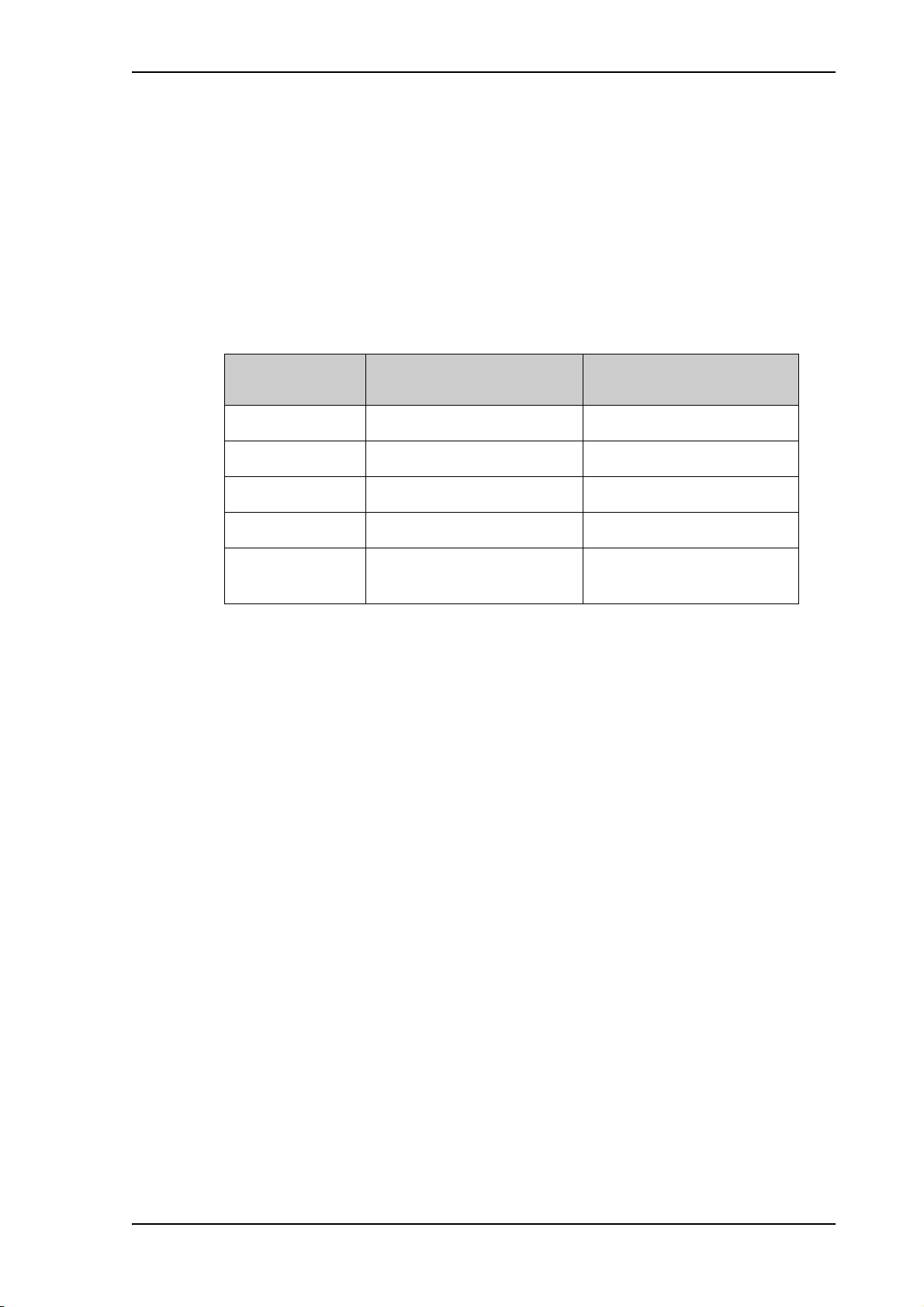
VIM modules. The electronic design guarantees that minimum 20 dB RF loss @ 1700
MHz in the antenna cable will work, but typically an RF loss of about 25 dB will be
within the limits of the cable calibration. You can verify the cable attenuation margin with
the cable calibration. See Cable calibration on page 5-11 for more details.
The DC-resistance loop of the antenna cable must be maximum 0.9 Ohm. This is to
ensure the power requirements from ACU to the antenna and to ensure the performance of
the system. Preferably choose one of the cable types listed in the table below.
Installation of the ADU
Cable Type
Absolute maximum length
(m)
Absolute maximum length
(ft)
RG223-D 25 m 80 ft
RG214/U 50 m 160 ft
S 07272B-05 95 m 310 ft
LMR-600-50 135 m 440 ft
LDF4.5-50
300 m 980 ft
Andrew
Table 2-7: ADU cable types and maximum lengths
Check the data sheet from the cable supplier that both the RF- attenuation and the DCresistance are kept within the maximum specified values:
• ADU cable RF-attenuation at 1700 MHz: max. 20-25 dB including connector.
• ADU cable modem-attenuation at 10 MHz: Max. 2 dB
ADU cable modem-attenuation at 36 and 54 MHz: Max. 4 dB
• ADU cable loop DC-resistance max: 0.9 Ohm.
Also ensure that the specified minimum bending radius is respected. If this is not the case,
the loss in the cable will increase. Check the documentation from the cable supplier.
2-25
Page 50
Installation of the ACU
Set to ON
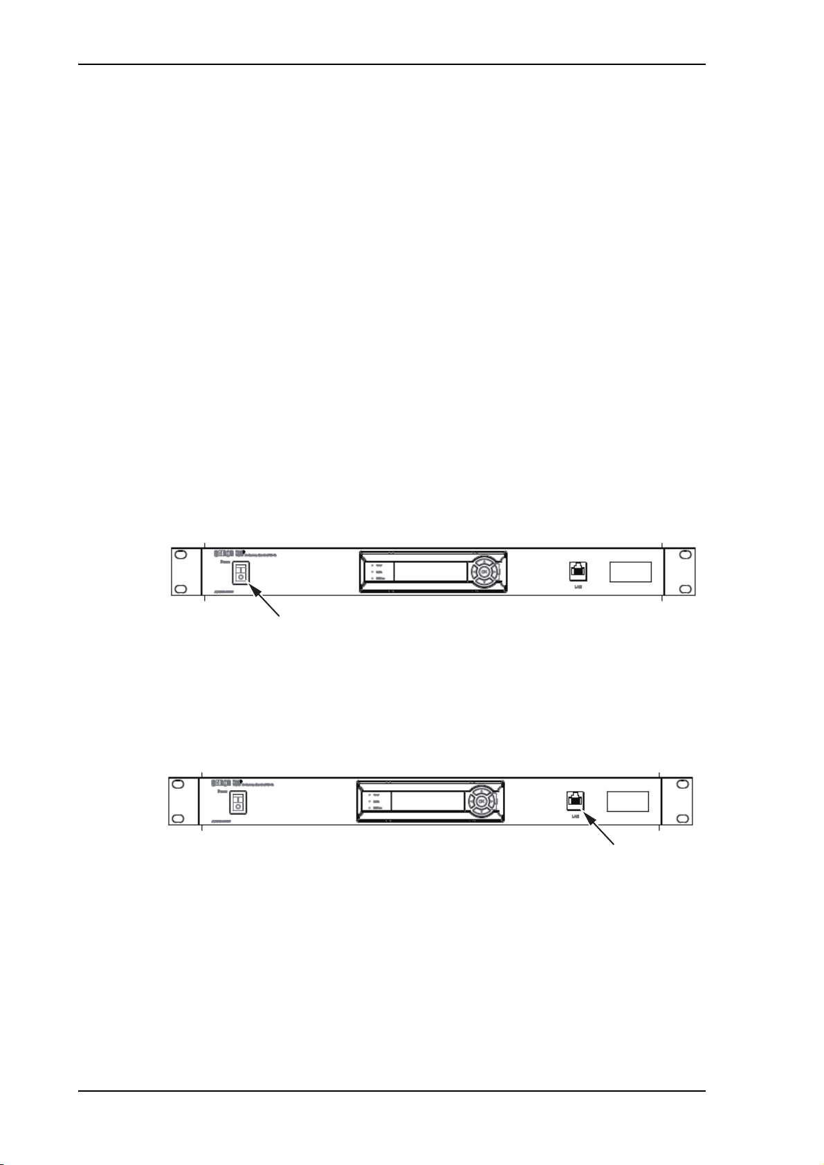
2.4 Installation of the ACU
The following sections describe the installation and grounding of the ACU.
When selecting a mounting location, keep in mind the following points:
• Locate the 19” rack where maintenance can easily be done.
• Separate the 19” rack 30 to 50 cm from a bulkhead.
2.4.1 To install the ACU
A cable relief bracket is already mounted when receiving the ACU. The cable relief is a
simple system to secure cables with cable strips. It offers a number of holders to which
you can secure the cables from the ACU. To install the 19” rack version of the ACU, do
as follows:
1. Slide the ACU into a 1U space in a 19” rack.
2. Mount the screws in each side through the holes in the front and fasten the screws to
the rack. Make sure that the unit is mounted securely using the optional support
bracket according to the requirements for your 19” rack.
3. Connect all cables. See Interfaces of the FV-110 ACU on page 3-1 for a description of
the ACU connectors.
Figure 2-22: ACU, On/off switch
4. Set the On/Off switch at the front of the ACU to On.
For a description of the connectors see ACU connector panel — overview on page 3-1.
The ACU has additionally a LAN connector at the front for accessing the service port
from the ACU front panel.
Service port
Figure 2-23: ACU, LAN connector at the front: Service port
2-26
Page 51

2.4.2 To ground the ACU
Make sure that the grounding requirements are met. See the appendix Grounding and RF
protection on page F-1 for details about grounding.
ADU cable
The ADU is connected to the ACU with the ADU cable (coax cable) with an N connector
at both ends. For information on ADU grounding, see To ground the ADU on page 2-24.
At the ACU end, it is strongly recommended to ground the ADU cable. Use a short cable
from the ACU to a grounding point in the rack and connect the short cable to the ADU
cable at this grounding point, making sure the shield of the connector is properly
connected to the rack.
Ground stud at the ACU
To ensure that the ACU is grounded – also if the ADU cable is disconnected from the
ACU, connect an extra ground wire from the rack to the ground stud on the ACU. This
ground wire must be a heavy wire or braid cable with a larger diameter than the coax
cable.
Installation of the VMU
Figure 2-24: ACU, 19” rack version, ground stud
2.5 Installation of the VMU
For a list of supported VSAT modems see Figure 5-17: Web interface: SETTINGS,
Modem profile – supported modems.
2.5.1 General mounting considerations — VMU
1. Mount the VMU close to the ACU, preferably at a distance < 1 m.
2. Connect all cables. See VMU settings on page C-1 for a description of the connectors
for supported VSAT modems.
For cable specifications see VMU cables on page B-1.
Connectors and pin-out of the VMU
For connectors and pin-out see the user documentation of the VMU and Interfaces of the
VMU on page 3-5.
Wiring Power
Provide power to the VMU, see the user documentation of the unit.
2-27
Page 52

To install the dual-antenna mode (optional)
TCP/IP Master/Slave control
ACU/Modem control
VSAT modem
2.6 To install the dual-antenna mode (optional)
You can use the FV-110 in dual antenna mode with 2 ADUs, 2 ACUs and the dualantenna accessories kit. The kit consists of two 75 Ohm RF cables, an RF splitter and an
RF combiner. In case one antenna enters a blocking zone, the other antenna of the dualantenna system takes over and the system continues working.
There is a Master ACU and a Slave ACU. The VSAT modem is connected to and
configured in the Master ACU. The Slave ACU is configured as a slave unit. It is
connected with an Ethernet cable to the Master ACU from which it gets all satellite
information.
The switching from one antenna to the other is done based on the programmed blocking
zones in the two antennas and takes effect whenever signal blockages occur from cranes
etc.
2-28
Figure 2-25: Dual mode antenna, overview
To install the dual antennas, do as follows:
1. Install the master ADU, ACU, the RX combiner and the VSAT modem as shown in
figure 2-25.
2. Install the slave ADU, ACU, the TX splitter as shown below.
3. Provide vessel heading input to the master ACU and slave ACU, see NMEA 0183
connector on page 3-3.
Page 53

To install the dual-antenna mode (optional)
4. Connect the cables as shown below and in the table below.
Figure 2-26: Dual mode antenna, connecting cables (example)
Connect cables Purpose
Master ACU LAN port 2 to Slave
Master/Slave control
ACU LAN port 2
Master ACU LAN port 1 or RS 232 to
VSAT
modem control
VSAT modem control
Master ACU Rx Out to the Rx
Rx when Master active
combiner input 1
Slave ACU Rx Out to the Rx combiner
Rx when Slave active
input 2
Rx combiner output to VSAT modem RxRx to VSAT modem
Master ACU Tx In to the Tx splitter
output 1
Slave ACU Tx In to the Tx splitter
Enabled when Master
active
Enabled when Slave active
output 2
Tx splitter input to VSAT modem Tx Tx from VSAT modem
Table 2-8: Dual mode antenna, cabling
2-29
Page 54

To install the dual-antenna mode (optional)
This page is intentionally left blank.
2-30
Page 55

Chapter 3
LAN3 (Service)
to front
NMEA
RS-232
RS-422
Ground
RX Out
TX In
LAN1 to 4
LAN1, 2: Modem Control
AC power
Fuse 7AT/SB
Antenna
Interfaces
This chapter is organised in the following sections:
• Interfaces of the FV-110 ACU
• Interfaces of the VMU
3.1 Interfaces of the FV-110 ACU
3.1.1 LEDs, display and keypad
Figure 3-1: ACU — LEDs, display and keypad
3
3.1.2 ACU connector panel — overview
Figure 3-2: ACU: LEDs, display and keypad (detailed)
Figure 3-3: ACU rack version, connector panel overview
The connector LAN on the front panel is typically connected to the service port at LAN3
with a straight Ethernet cable. Then you can access the service port from the front of the
ACU rack version.
3-1
Page 56
Interfaces of the FV-110 ACU
Important
3.1.3 ADU connector
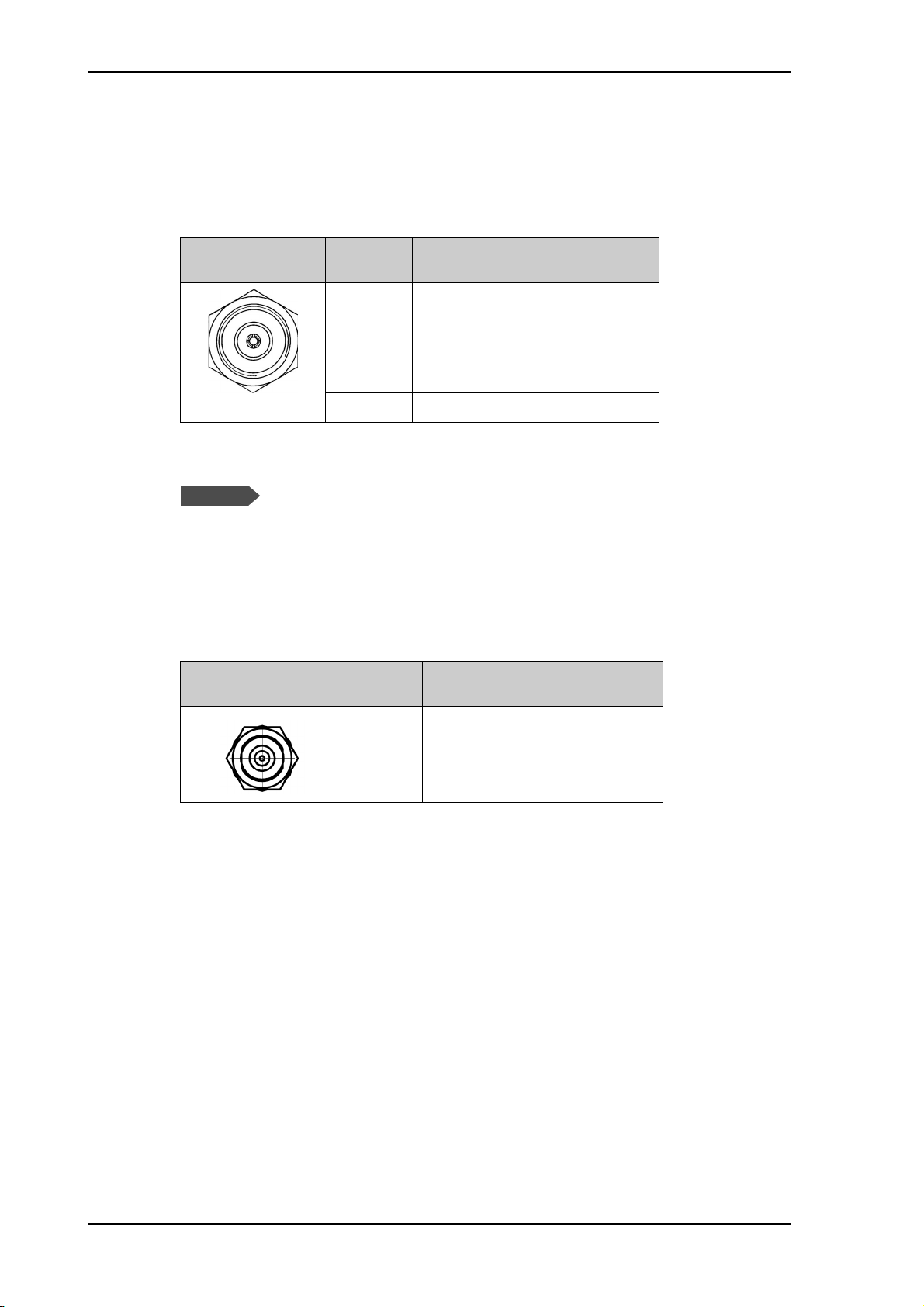
There is just one cable from the ACU to the ADU. This is used to power the ADU, supply
10 MHz clock, handle all communication between ACU and ADU, and deliver the VSAT
Rx and Tx signals.
Outline
(on the ACU)
Conductor Pin function
Inner DC to ADU
Outer GND (Shield)
Table 3-1: N connector, outline and pin assignment
Do not use TNC connectors on the ADU antenna cable
or on pigtails. TNC connectors cannot carry the DC
current for operating the ADU.
3.1.4 Rx/Tx connectors for VMU
Connect the Rx and Tx channels of the VMU to the Rx and Tx connectors of the ACU
with the 2 supplied Rx/Tx cables (75 Ohm coax, F-F, 1 m).
Outline
(on the ACU)
Pin
number
10 MHz clock to ADU
ACU to ADU internal
communication
VSAT Rx/Tx
Pin function
1 Inner conductor:
10 MHz clock, VSAT Rx/Tx
2 Outer conductor: GND (Shield)
Table 3-2: F connector, Rx and Tx, outline and pin assignment
For step-by-step guidelines how to set up the VSAT modem see VMU settings on page C-
1.
3-2
Page 57

3.1.5 NMEA 0183 connector
1 11
Connect the ship’s gyro to this connector.
Interfaces of the FV-110 ACU
Outline (on the ACU) Pin Pin function
1 Not connected –
2 NET-H (NMEA 2000) White
3 NET-L (NMEA 2000) Blue
4 NET-S (NMEA 2000) Red
5 NET-C (NMEA 2000) Black
6 Not connected –
7 Not connected / RS-232 RX NMEA
0183
8 RS-232 GND
RS-422 shield, connect only one
end.
9 RS-422 RX Line B (+) NMEA 0183
10 RS-422 RX Line A (-) NMEA 0183
11 Not connected –
Table 3-3: NMEA 0183/2000 connector, outline and pin assignment
Wire
color
–
NMEA 0183
(Hardware prepared for NMEA 2000, for future use)
NMEA 2000 power: 9-16 VDC. NMEA 2000 LEN (Load Equivalency Number): 2
(100mA)
The NMEA 0183 connection supports IEC 61162-1 and IEC 61162-2.
• IEC 61162-1, baud rate 4800, format 8N1.
• IEC 61162-2, baud rate 38400, format 8N1.
The baud rate is auto detected by the ACU, the user cannot configure this interface.
Supported NMEA string:
1. HEHDT (North seeking Gyro compass)
2. GPHDT (GPS compass)
3. HNHDT (Non-North seeking gyro compass)
4. IIHDT (Integrated Instrument)
5. HCHDT (Magnetic compass)
3-3
Page 58
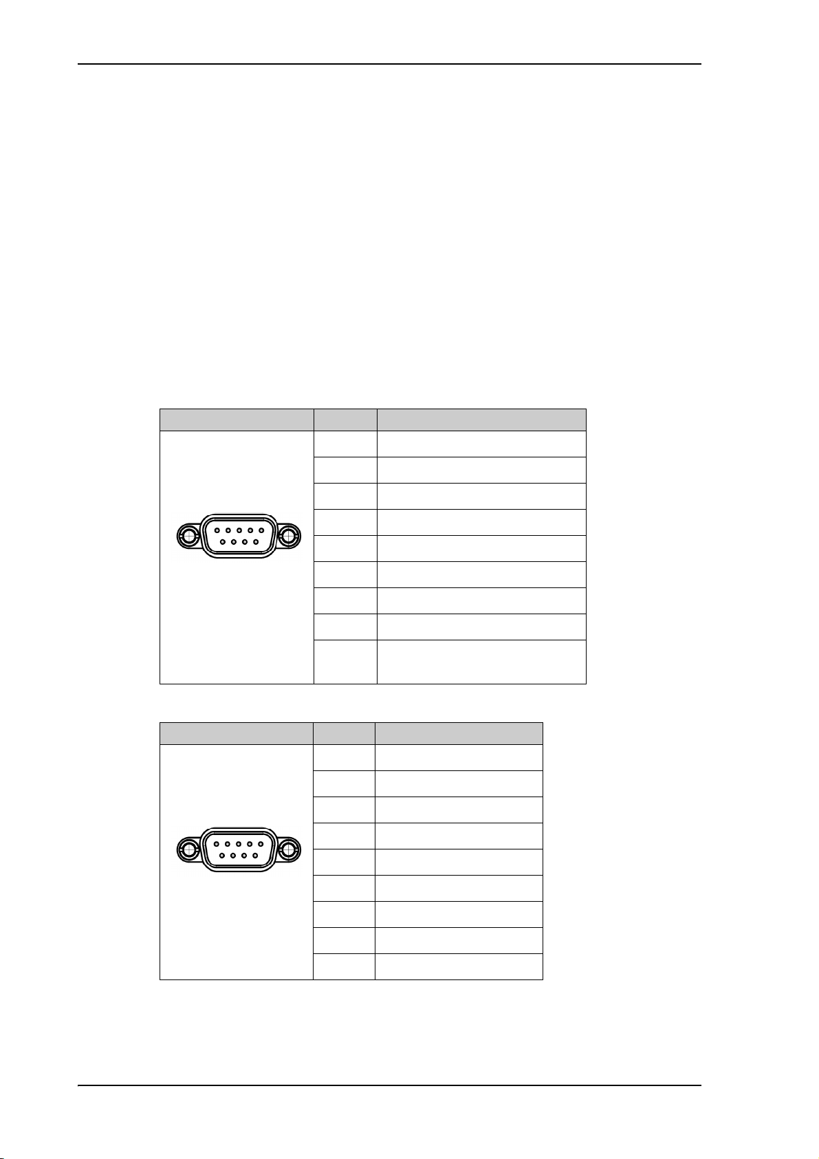
Interfaces of the FV-110 ACU
15
69
15
69
Recommended NMEA 0183 cable:
Two-wire constructed with one enclosed shield
Network signal pair:
• Size: No. 24 AWG (0.24 sq. mm) or heavier
• Characteristic impedance: 95 - 140 Ohm
• Propagation delay: 5 nanoseconds per meter, maximum
• 15 Twists (minimum) per meter
3.1.6 RS-232 and RS-422 connectors
Use these connectors to connect the ACU to the VSAT modems with serial interfaces. See
Interfaces of the VMU on page 3-5 for further details about the RS-232 or RS-422
connector.
Outline (on the ACU) Pin Pin function
1 Not connected
2RXD
3TXD
4DTR
5Ground
6DSR
7RTS
8CTS
9 Receive Signal Strength
Indicator
Table 3-4: RS-232 connector, male, outline and pin assignment
Outline (on the ACU) Pin Pin function
1Ground
2Line A RXD (+)
3Line B TXD (+)
4Ground
5Ground
3-4
6 Not connected
7 Line A RXD (-)
8Line B TXD (-)
9 Not connected
Table 3-5: RS-422 connector, male, outline and pin assignment
Page 59

3.1.7 LAN1, LAN2, LAN3 and LAN4 connectors
3RUW 3RUW
3RUW 3RUW
6HUYLFHSRUW
1HWZRUN
96$7PRGHPFRQWURO
1HWZRUN
1HWZRUN
Four Ethernet connectors (type RJ45) for PC/lap tops, routers, wireless access points. The
maximum cable length per connection is 100 m. Depending on the VMU connected, a
LAN connector may be used for modem control.
Figure 3-4: LAN connectors
Interfaces of the VMU
Cable type: CAT5, shielded.
For information how to configure the LAN network see To configure the LAN network on
page 5-29.
Outline Pin Pin function Wire color
1 Tx+ White/orange
2Tx- Orange
3 Rx+ White/green
4 Not connected Blue
5 Not connected White/blue
6Rx- Green
7 Not connected White/brown
8 Not connected Brown
Table 3-6: Ethernet connector, outline and pin assignment
3.2 Interfaces of the VMU
For interfaces of the VMU and how to connect a VMU correctly to the ACU the user
documentation of the VMU. For step-by-step guidelines how to set up the VSAT modem
see Appendix C, VMU settings.
3-5
Page 60

Interfaces of the VMU
This page is intentionally left blank.
3-6
Page 61

Chapter 4
Steady
Green
Connecting power
This chapter is organised in the following sections:
• Power up
4.1 Power up
4.1.1 Procedure
1. Connect power to the VMU.
2. Switch on the ACU. The unit starts up and goes through an initialization procedure:
• ACU POST
• ADU Initializing
• ADU POST
• READY
This may take some time (up to a couple of minutes).
3. The FV-110 is ready to be calibrated (for first time power up) or receive data from the
VSAT modem (when in normal operation). The ACU display shows the following
message:
4
Figure 4-1: ACU display after first power on (example with LAN ports 1 and 4 used)
The LEDs Power and Fail/Pass are steady green, the LED Logon is off. For further
information on status indicators see Status signalling with LEDs and status messages
on page 7-7.
Make sure there are no hardware failures or error codes present, check the display of
the ACU for events. For more information on error codes and events see
Troubleshooting on page 7-12 and System messages on page G-1.
4. Continue to get the FV-110 system operational, do the following:
• Make a cable loss and an azimuth calibration.
• Create VSAT modem profiles.
• Create one or more satellite profiles.
For step-by-step instructions, see Introduction to the built-in web interface on page 5-1.
For installation check lists see, Installation check on page 6-1.
4-1
Page 62

Power up
4.1.2 Initialisation steps in daily use
Once the system is configured and a satellite profile is active, the startup sequence is as
follows:
• ACU POST
• ADU Initializing
• ADU SW upload (If the software versions in the ADU and ACU are not the same, a
software update is done during startup.)
• ADU POST
•READY
• POINTING ANTENNA
• ACQUIRING SIGNAL
• TRACKING
4.1.3 FV-110 operational
When the display shows TRACKING and the LED Logon is steady green, the system is
operational.
4-2
Page 63

Chapter 5
Important
Configuration
This chapter is organised in the following sections:
• Introduction to the built-in web interface
• Calibration
• Configuration with the web interface
• Keypad and menus of the ACU
• SNMP support
5.1 Introduction to the built-in web interface
5.1.1 Overview
Use the built-in web interface (installation of software is not necessary) of the FV-110
ACU to make a full configuration of the FV-110 with the correct VMU, the satellite
positions you intend to use and other parameters. You can use a standard Internet
browser.
5
For quick start instructions see Calibration on page 5-3.
The FV-110 system is not designed to be connected directly to the Internet.
It must be located behind a dedicated network security device such as a
firewall.
If any ports of the FV-110 are exposed to the Internet you must change the
default passwords as anyone with access and malicious intent can render the
FV-110 inoperable.
5.1.2 Connecting to the web interface
To connect to the web interface of the ACU do as follows:
1. Power up the FV-110 system, i.e. switch on the ACU. Wait until the LEDs on the front
plate of the ACU show that the system is ready to be configured.
• Power LED: Green
• Logon LED: Off
• Fail/Pass LED: Flashing green, during power-on self test, after that steady green.
2. Connect a PC to LAN interface 3 (Service port, standard Ethernet) of the ACU or to
the front LAN connector of the ACU.
5-1
Page 64

Introduction to the built-in web interface
Figure 5-1: LAN connector used for configuring the FV-110
3. Open your Internet browser and enter the IP address of the ACU. The default IP
address is http://192.168.0.1.
4. The web interface shows the DASHBOARD page.
5-2
Figure 5-2: FV-110 Dashboard
When the Dashboard is displayed you have verified that the connection to the FV-110 can
be established. The web interface is ready for use. You can continue to configure the
system.
If you cannot establish a connection there might be problems with the Proxy server
settings of your PC. See Proxy server settings in your browser on page 5-18 for further
information. For a detailed introduction to the web interface see Overview and dashboard
on page 5-16. If you want to use another LAN port you must configure it according to
your network requirements. For information how to configure the LAN connectors see To
configure the LAN network on page 5-29.
For a detailed introduction to the web interface see Overview and dashboard on page 5-
16.
Page 65

5.2 Calibration
Important
Note
Before the FV-110 can be used you must select a heading input setting in order to make
an azimuth and cable calibration. The azimuth calibration is required in order for the FV110 to determine the offset of the ADU zero direction to the bow-to-stern line of the ship.
This procedure is fully automatic. The satellite data for calibration can be entered directly
on the calibration page or you can define a Service profile to be used for the azimuth
calibration. A cable calibration is required in order to record the cable characteristics of
the antenna cable which is used in the FV-110 fixed gain feature. See Fixed TX gain
principle on page 5-15 for more information.
After the calibration you create the satellite and VSAT modem profiles you want to use
during normal operation, and you can set up blocking zones for the specific installation.
You must logon as an administrator to do a calibration.
See Administration on page 5-40.
The following sections describe the steps for a successful calibration:
• Heading mode and position mode
Calibration
• Azimuth calibration
• To set up a service profile for calibration
• Cable calibration
• Operation in gyro-free mode
• Flow chart for calibration (user controlled)
• To make a line up procedure
• Fixed TX gain principle
5.2.1 Heading mode and position mode
You must set the heading mode and the position mode before you start the calibration
procedure.
If you change the heading settings from external to fixed or vice versa you must
make a new azimuth calibration.
1. Go to the page SETTINGS > Navigation.
2. Select the desired heading input.
5-3
Page 66
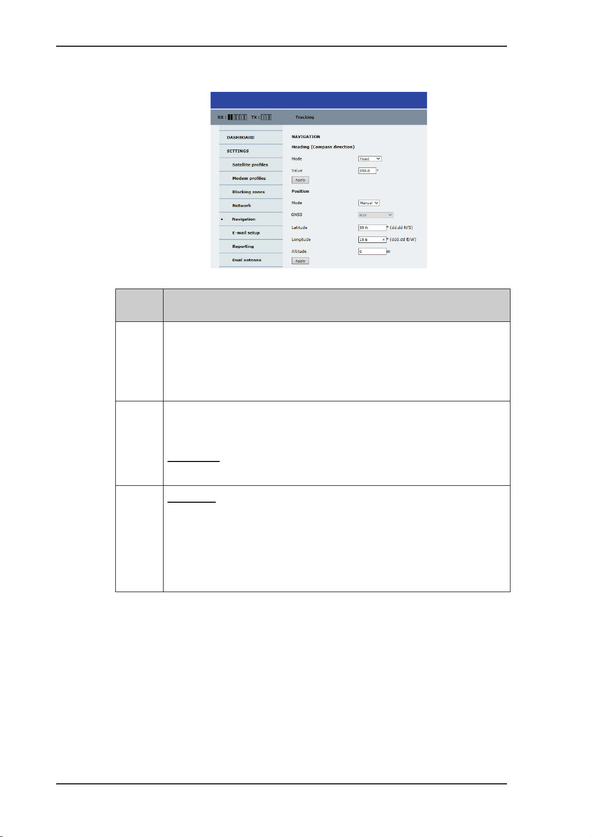
Calibration
Figure 5-3: Web interface: SETTINGS, Navigation
Heading
mode
Description
External Heading input from the vessel’s gyro compass (default).
If there is no heading input due to failure, alarms are raised and the antenna
continues in gyro-free mode. When heading input is available again and a
new acquisition is made, alarms are cleared. See also Operation in gyro-free
mode on page 5-11.
Fixed Use this setting for making an azimuth and cable calibration if there is no
input from the vessel’s gyro compass and for permanent installations like
remote areas or oil rigs, or during training and test.
Important:
Do not use fixed heading mode for vessels underway.
If using fixed heading mode, set to External before leaving port.
None I
mportant: You must make an azimuth and cable calibration with Fixed
before you can use this setting. This is required in order to be able to use
blocking zones. After a successful azimuth and cable calibration you
must change the heading input setting from Fixed to None.
Select this setting after a successful azimuth calibration with Fixed heading if
the system does not have input from the vessel’s gyro compass. See also
Operation in gyro-free mode on page 5-11.
5-4
Table 5-1: Heading mode options
3. Click Apply.
4. Select the desired position mode.
Page 67

Calibration
Position
mode
Mode Select one of the following:
• GNSS (default)
•Manual
Important:
Do not use manual GPS input for vessels underway.
If using manual GPS input, set to GNSS before leaving port.
a
GNSS
Select one of the following:
• GPS (default)
•BEIDOU
• GPS + BEIDOU
• GLONASS
• GPS + GLONASS
Latitude,
Enter the values if you have set the Position Mode to Manual.
Longitude,
Altitude
Description
Table 5-2: Position mode options
a. This is only available if the antenna’s GNSS module supports GLONASS and
BeiDou.
5. Click Apply.
Acquisition process and search pattern
ith heading input or fixed heading
W
1. The FV-110 starts the acquisition, searches for 10 seconds at the expected position. If
RX lock is detected the FV-110 goes to Tracking.
2. If no RX lock is detected, a box search pattern is started and the positions where RF
power can be received are stored.
Figure 5-4: Acquisition, search pattern
3. The FV-110 checks each stored position for up to 10 seconds. If RX lock is detected
for more than 20% of the time, the FV-110 goes to Tracking.
5-5
Page 68
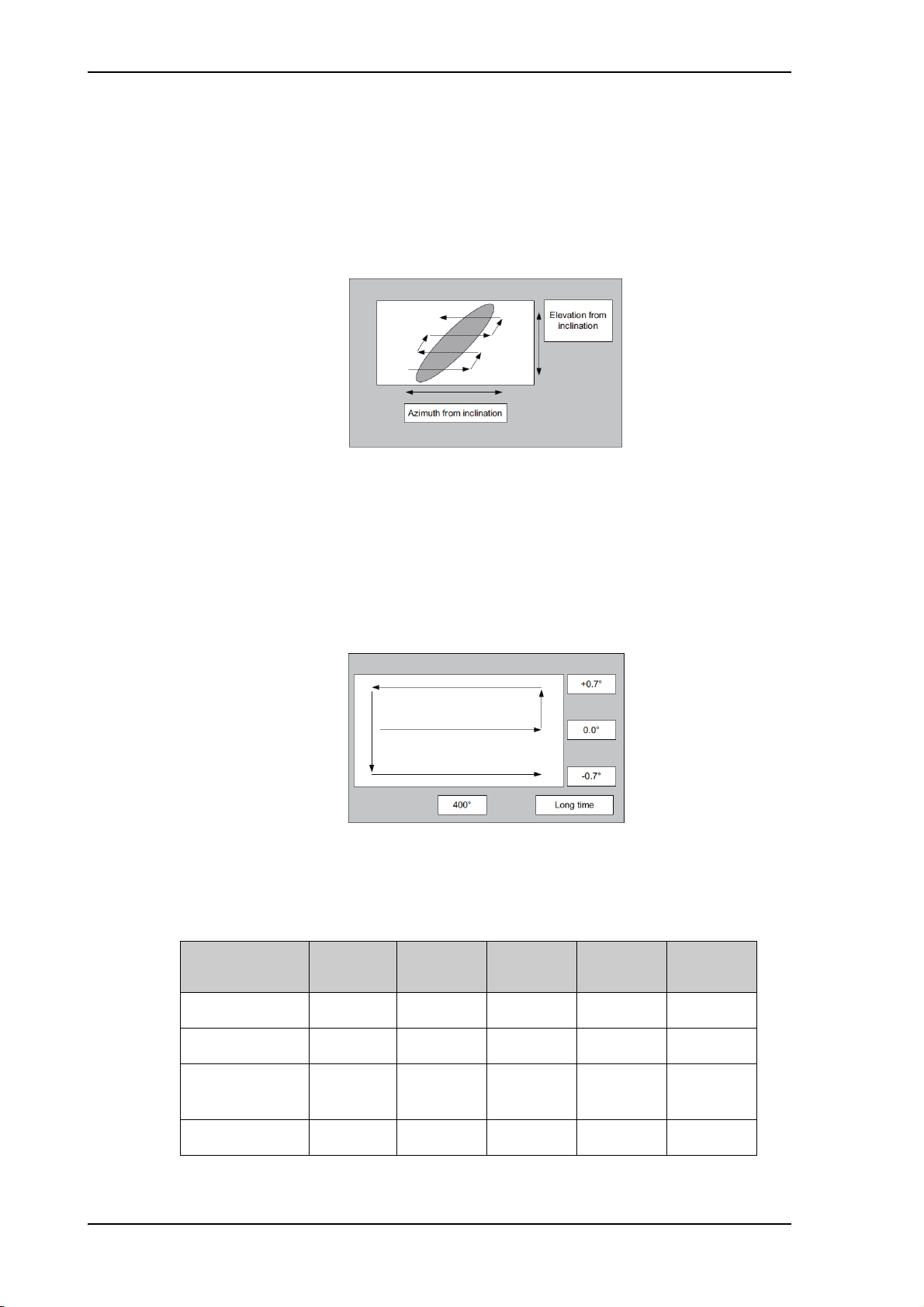
Calibration
With heading input or fixed heading, Inclined Orbit Satellite
1. The FV-110 starts the acquisition, searches for 10 seconds at the expected position. If
RX lock is detected the FV-110 goes to Tracking.
2. If no RX lock is detected, a box search pattern is started and the positions where RF
power can be received are stored.
Figure 5-5: Acquisition, search pattern for inclined orbit
3. The FV-110 checks each stored position for up to 10 seconds. If RX lock is detected
for more than 20% of the time, the FV-110 goes to Tracking.
Without heading input and not fixed heading (Gyro-free)
1. A box search pattern is started and the positions with reception of RF power are
checked for up to 10 seconds. If RX lock is detected for more than 20% of the time, the
FV-110 goes to Tracking.
Figure 5-6: Acquisition, search pattern in gyro-free mode
FV-110 acquisition times
Activity
Inclination0°Inclination 1°Inclination 2°Inclination 3°Inclination
4°
5-6
Initial search 10 s 10 s 10 s 10 s 10 s
Scan box pattern 5 s 10 s 15 s 25 s 30 s
Validate result
10 - 30 s 10 - 30 s 10 - 30 s 10 - 30 s 10 - 30 s
(10 s per result)
Max. total time 25 - 45 s 30 - 50 s 35 - 55 s 45 - 65 s 50 - 70 s
Table 5-3: FV-110 acquisition time
Page 69

5.2.2 Azimuth calibration
Note
If the target satellite is in inclined orbit, the elevation range is extended
accordingly.
Azimuth calibration is done toward a satellite of a known position. After finding the
satellite, the system can calculate the azimuth offset of the ADU installation. The satellite
and transponder properties for the calibration can be selected from a list of service profiles
or supplied manually.
There are three ways to make an azimuth calibration:
• Automatic azimuth calibration with an active satellite profile
• Azimuth calibration (user controlled)
• Azimuth calibration with a service profile
Automatic azimuth calibration with an active satellite profile
You can enable automatic azimuth calibration, even if there is no line of sight to an
azimuth calibration satellite from the place of installation. To be able to use this feature
you must have made a valid satellite profile and have activated it. When the vessel leaves
the harbour and gets line of sight to the satellite, the system automatically finds and tracks
the satellite and makes the azimuth calibration. After a successful azimuth calibration the
ACU will automatically disable the setting Azimuth calibration (active satellite profile)
on the page SERVICE > Calibration.
Calibration
To enable automatic azimuth calibration, do as follows:
1. Create a modem profile, see Modem profiles on page 5-22.
2. Create a satellite profile, see Satellite profiles on page 5-24
3. Click SETTINGS and Activate the satellite profile.
4. Click SERVICE > Calibration.
Figure 5-7: Web interface: SERVICE, Calibration
5-7
Page 70

Calibration
Note
Important
Important
5. Select Enable in the section Azimuth calibration (active satellite profile).
6. Click Apply.
7. Switch on the modem.
Azimuth calibration (user controlled)
To make a user-controlled azimuth calibration, do as follows:
1. On the page SERVICE > Calibration, select User defined in the Satellite drop down
list.
Check that the satellite transponder is visible from the location of the installation
and that it is at an elevation angle between 10 and 70 degrees.
2. Type in the longitude and polarisation skew of the satellite. The polarisation skew is
provided by the satellite operator, it is typically 0 degrees. For satellite data see DVB-S
satellites on page E-1, www.lyngsat.com.
The calibration function is not able to verify the correctness or precision of
the supplied longitude. It is therefore important to supply the correct
longitude including the first decimal.
3. Select the polarisation of a transponder and type in its frequency and symbol rate.
4. Select which satellite identifier to use for identification of the signal.
Satellite
identifier
NID value Description
NID 0 Satellite identifier is not used.
NID 1–65535 Supplied NID is matched against Network ID broadcast
by the satellite.
Orbital position n.a. Supplied longitude is matched with orbital position
broadcast by satellite.
Not all service providers broadcast the orbital position.
Table 5-4: Satellite identifier and NID values
5. Click Start and wait typically 5 minutes for the calibration to finish. A progress bar is
shown during calibration and a message is displayed when the calibration has
completed. In case of failure, see the table in the following section for a description of
error codes during calibration.
It is strongly recommended to verify the result of a calibration performed
with user defined data. This can be done by making a new calibration on a
different satellite and verify that the resulting Azimuth calibration value
differs less than one degree.
5-8
Page 71

Calibration
The following table shows the error codes that might be displayed during a calibration.
Error
code
1 The elevation of the selected satellite is too low. Select another satellite.
2 The elevation of the selected satellite is too high. Select another satellite.
4 The calibration values could not be saved. Possibly due to defective hardware.
5 The antenna could not point with sufficient precision. Check that the antenna is
mounted in a stable way. Other possible causes might be electrical or
mechanical faults.
6 No signal received. Check that there is free line of sight. Try again or try with
another satellite.
7 RF setup error, e.g. missing or invalid TX frequency.
8 Invalid satellite, e.g. satellite not visible.
Table 5-5: Possible error codes during calibration
Azimuth calibration with a service profile
Explanation
1. Click SERVICE > Calibration.
2. Select the service profile in the drop down list Satellite. All profiles with the VSAT
modem Service & Calibration are displayed in the list. If there is no profile in the list
see To set up a service profile for calibration on page 5-9.
3. Click Start in the section Azimuth calibration and wait typically 5 minutes for the
calibration to finish. After finished calibration a message with the result of the
calibration is displayed.
5.2.3 To set up a service profile for calibration
If you do not want to use the automatic azimuth calibration or if you want to enter the
satellite parameters directly on the calibration page, use this calibration method. To
prepare for calibration you can set up a service profile for calibration.
To setup a service profile do as follows:
1. Open your Internet browser and enter the IP address of the ACU. The default IP
address is http://192.168.0.1.
2. Select SETTINGS > Satellite profiles > New entry. Enter the name of the satellite
profile for calibration (a name of your own choice).
5-9
Page 72

Calibration
3. Select the VSAT modem profile Service & Calibration from the drop-down list.
Figure 5-8: Service profile for calibration
4. Enter the data for the satellite that you want to use as a calibration reference. You can
enter the satellite data manually or select a satellite from the list of predefined satellites
(Eutelsat). For satellite information see DVB-S satellites on page E-1 or
www.lyngsat.com.
Note the following calibration requirements:
Satellite requirements for successful calibration
Elevation Elevation angle: 5 – 70 degrees
Not allowed for calibration: Inclined orbit.
System encryption DVB-S or DVB-S2
Polarisation Horizontal or vertical polarisation.
Not allowed: Left-hand circular (L) or right-hand circular (R).
Symbol rate The DVB symbol rate must be >5 Ms/s.
NID Preferably a unique NID (ONID).
An azimuth calibration without NID can be useful in regions
where the satellite operators do not broadcast NID (US, China,
Australia etc.).
For NID=0 the NID is not used when checking the satellite link.
5-10
Table 5-6: Satellite requirements for elevation and carrier
Elevation cutoff: Not relevant for calibration.
LNB: Co-pol or X-pol, use this for test if both the LNBs and RX cables function
properly in case of issues with the reception of a signal. The polarisation must remain
the same as stated for the transponder used for the azimuth calibration. The antenna
will just turn the polarisation motor 90 degrees to use the other LNB to receive the
same signal.
5. Click Apply to save the settings for the service profile for calibration. The system is
ready for the azimuth and cable calibration.
Page 73

5.2.4 Cable calibration
Important
1. On the page SERVICE > Calibration click Start in the section Cable calibration.
Figure 5-9: Web interface: SERVICE, Calibration, cable attenuator margin
Wait typically for 2 minutes for the calibration to finish. A message is displayed when the
calibration has been completed successfully.This screen shows how much attenuation
margin is left for the antenna cable. This indicates whether the antenna cable and
connectors are in good condition and well crimped.
It is recommended to make a cable calibration when servicing the system to check if the
antenna cable is still in good order. If the attenuator margin changes by 2 dB or more after
a cable calibration, it is recommended to do a P1dB compression measurement to verify
that the VSAT modem configuration is correct.
Calibration
The FV-110 is calibrated now. If the calibration failed there will be a message on the
calibration screen.
For operation when input from the vessel’s gyro compass is not available:
Change the heading input setting from Fixed to None at Heading – Input.
Fixed heading is not allowed for sailing vessels!
5.2.5 Operation in gyro-free mode
Heading input: none
If input from a gyro compass is not available, information from the GPS position is used
when searching for a satellite.
When the VSAT antenna does not have ship heading input from the vessel's gyro
compass, the azimuth direction of the satellite is not known. In this case the antenna will
start a 360 degrees sky scan and scan until it finds a satellite. The satellite search time to
find the satellite and start tracking is therefore raised considerably. If the ship is on a
steady course and sails at a speed over ground above 5 kn, the system can use an
estimated heading from the current GPS position. This will reduce the search time, but it
will still be a longer search time than with heading input.
This mode can be difficult for inclined orbit satellites and elevations <5 and >70 degrees,
see the following sections for details.
If a VSAT system loses the signal from the satellite, i.e. due to blockage, and the duration
of signal loss is longer than approximately 1 minute, a system without heading input must
do a new sky scan to find the satellite when the antenna is out of blockage.
Inclined orbit satellites
If the wanted satellite is an inclined orbit satellite, the VSAT system does not have any
information of the satellite latitude position but only information about inclination. This
means longer search times, depending on the maximum inclination. With the increased
search time for a system without heading input the search time can be so long that it will
be more or less useless in practice.
5-11
Page 74

Calibration
Tracking for satellite elevation between 5 and 75 degrees
When the VSAT system has found the satellite and is in pointing mode, the performance
of a system with heading input and a system without heading input will be very similar.
Note that this is only the case for a satellite elevation range from 5 to 75 degrees.
If the satellite is an inclined orbit satellite, the missing heading information introduces a
polarization error depending on the satellite elevation and the inclination. Normally it is
required that the polarization is controlled within 1 degree towards the satellite. This gives
the following limit for use of inclined orbit satellites (a purely physical limit), and all
systems without heading input have this limit.
Satellite
elevation
Max allowed inclination
Satellite
elevation
Max allowed inclination
<20 2.5 <70 0.3
<50 0.7 ≤75 0
Table 5-7: Satellite elevation and max. allowed inclination
Tracking for satellite elevation above 75 degrees
It is not possible to use a system without heading input from the vessel's gyro compass
with satellites at an elevation of higher than 75 degrees because the system will not have
the required polarization accuracy of the transmitted signal.
5-12
Page 75

5.2.6 Flow chart for calibration (user controlled)
The following flow chart gives an example of the steps in a calibration.
Calibration
Figure 5-10: Example for a calibration – step by step
5-13
Page 76

Calibration
Note
Step 3
Step 4
5.2.7 To make a line up procedure
The ship must not move during the calibration procedure.
The FV-110 has been tested at the factory and online on a live satellite link to calibrate the
TX polarisation unit. You can fine-tune the TX polarization by doing a line up as
described below. To do the line up, do as follows:
1. Open your Internet browser and enter the IP address of the ACU. The default IP
address is http://192.168.0.1.
2. Create a VSAT modem profile and a satellite profile using the previously created
VSAT modem profile (See To set up a service profile for calibration on page 5-9).
3. Go to the page SERVICE > Line up. As soon as the antenna is in tracking mode and
points to the satellite, the text next to Status shows: Please wait. Improving tracking.
This may take up to 2 minutes. Wait until the text shows: Ready for activation.
Figure 5-11: Web interface: SERVICE, Line up: Ready for activation
4. Click the button Activate lineup and wait until the status field shows Antenna ready.
Follow the instructions from your service provider.
Figure 5-12: Web interface: SERVICE, Line up: Antenna ready
5-14
Page 77

Calibration
FV-110 ADU
FV-110
ADU
5. Enter the Modem CW frequency (Continuous Wave) in GHz.
This is provided by the satellite operator, typically when talking to the satellite
operator on the phone before starting the line up.
6. Set the values as advised by the service provider:
• TX polarisation
•Azimuth
• Elevation
7. If needed, add 90 degrees to the TX polarisation by selecting the field.
8. To save the TX polarisation offset value, click the button Save polarisation offset.
9. Follow the instructions from the service provider to make a P1dB compression test
(VSAT modem).
10.Click the button Deactivate to finish the line up procedure.
When finished, the saved value for TX polarisation is visible the next time the line up
procedure is selected.
5.2.8 Fixed TX gain principle
The FV-110 uses a new transmitter chain concept. After calibration it provides a fixed
gain of 44 dB from the Tx-port of the ACU to the output of the BUC. Advantages of the
fixed TX gain principle are:
• Fixed TX gain over frequency and cable length
• TX gain independent of antenna cable length
• Utilization of the full 8W BUC power over frequency
• P1dB compression point the same over frequency
When installing the FV-110 you make a cable calibration. At that point every installation
finds the same P1dB compression setting regardless of cable length. The P1dB
compression point is approximately -5 dBm at the ACU Tx-port. Additionally the FV-110
system monitors the TX gain in real time.
Figure 5-13: Fixed TX gain principle (FV-110)
* You find the maximum cable loss at Maximum allowed RF loss in the ADU cable on
page 2-22.
Example: ACU Tx-port power: -5 dBm > BUC output = +39 dBm (compression)
5-15
Page 78

Configuration with the web interface
5.3 Configuration with the web interface
5.3.1 Overview and dashboard
Topics in the web interface
Use the site map to get an overview over the existing menus, submenus and topics. You
can click on each menu in the site map to go directly to the page or display the respective
submenu.
5-16
Figure 5-14: Topics in the web interface (SITE MAP)
Page 79

Dashboard and navigation
1
2
3
The Dashboard is the first screen that is displayed when the user or administrator enters
the IP address of the web interface of the ACU. The Dashboard is used for viewing
properties and status of the ACU and ADU.
The web interface consists of the following sections:
Configuration with the web interface
Figure 5-15: Web interface: DASHBOARD of FV-110
1. The navigation pane contains the menus. You can click an item in the menu to open the
list of submenus or a new page in the contents section. The currently displayed menu is
marked by a bullet.
2. The top bar shows the following:
• RX signal strength bars: This shows the tracking signal strength of the antenna. The
signal strength can vary during operation, depending on the current position
relative to the satellite. The signal strength of the VSAT modem is shown on the
DASHBOARD in the section MODEM, at Signal level.
• BUC output power bars: This indicates if the BUC is transmitting or not. This is a
unique feature of the SAILOR 900 VSAT High Power antenna. A built-in power
detector in the OMT developed by Cobham SATCOM makes it possible to measure
the power within a time window to be able to catch short TX bursts. The power
within the window is averaged and shown in the BUC output power bar graph on
the DASHBOARD. Not that this indicator is an averaged signal, it is not a real-time
indicator. After measuring a signal burst the bar graph falls slowly in order for the
user to be able to see short TX bursts.
The BUC output power indicator is very useful during installation as the service
engineer knows whether the antenna is transmitting or not and that the hub should
be able to monitor the transmission. It is also very useful when doing line up with
the hub as the service engineer can monitor the TX BUC output power level on the
DASHBOARD and watch when the output power approaches the P1dB
compression point which is at 4 bars.
5-17
Page 80
Configuration with the web interface
Note
Note
• Current status of the antenna, see Status field in the top bar on page 5-19.
• An icon for active events is displayed, if there are any.
Icon Explanation
An event is active. Click the icon to see a list of active events. The event
time is UTC time. For explanations of the event messages, see Event list on
page 7-2 and Event messages – overview on page G-1. Note that this icon
will remain in the icon bar as long as the event is active.
• Host name: This is shown on every page. It is useful to identify the system at
remote login and in reports from the system. The host name is recommended to
contain the name of the vessel. To change the host name see To configure the LAN
network on page 5-29.
3. The contents section shows the page selected in the navigation pane. This section is
used for viewing or changing settings, or for performing actions. For a description of
the individual items in the contents section see Sections on the Dashboard on page 5-
20.
Table 5-8: Web interface: Event icon
To navigate the web interface
• To expand a menu, click the menu in the navigation pane.
• To access status and settings, click the relevant subject in the navigation pane or click
the relevant icon in the icon bar. The status or settings are displayed in the contents
section.
• To get an overview over the submenus available, click SITE MAP in the navigation
pane. Click on items in the site map to go directly to the relevant location.
You can give access to some configuration settings for users that are not
administrators. For information see To set up user permissions on page 5-42.
Proxy server settings in your browser
If you are connecting your computer using a LAN or WLAN interface, the Proxy server
settings in your browser must be disabled before accessing the web interface. Most
browsers support disabling of the Proxy server settings for one specific IP address, so you
can disable Proxy server settings for the web interface only, if you wish. Consult your
browser help for information.
To disable the use of a Proxy server completely, do as follows:
The following description is for Microsoft Internet Explorer. If you are using a
different browser, the procedure may be different.
1. In Microsoft Internet Explorer, select Too ls > Internet Options > Connections >
LAN Settings.
5-18
Page 81
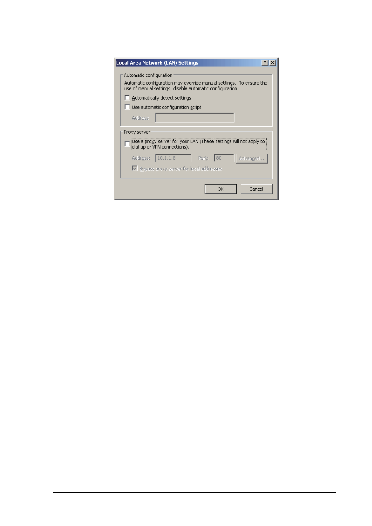
Configuration with the web interface
2. Clear the box labeled Use a proxy server for your LAN.
3. Click OK.
When the proxy server settings are disabled, close and restart your browser.
You may need to change this setting back on return to your Internet connection.
To connect a PC
To connect your PC to the ACU do as follows:
1. Connect a PC to LAN interface 3 (Service port, standard Ethernet) of the ACU or to
the front LAN connector of the ACU.
If you want to use another LAN port than LAN 3 you must configure it according to
your network requirements. For information how to configure the LAN connectors see
To configure the LAN network on page 5-29.
2. Open your Internet browser and enter the IP address of the ACU. The default IP
address is http://192.168.0.1.
Status field in the top bar
The top bar shows the current status of the antenna. Examples are:
• Not ready (waiting for input from GNSS, e.g. GPS)
• Antenna initializing
• Antenna SW upload
• Antenna POST error
•XIM data error
• Unrecoverable XIM data error
• System upgrade
• Antenna POST pending
• Antenna POST
5-19
Page 82

Configuration with the web interface
•Safe Mode (error, followed by an error description)
• Service switch (service switch in ADU activated)
•Ready (waiting for data from the modem or no satellite profile selected)
• Pointing antenna (locating the satellite)
• Acquiring signal (acquiring the satellite signal)
• Tracking (tracks the current satellite)
•Lineup (line up is activated)
• Azimuth calibration
• TX cable calibration
•Test
•Not ready (waiting for input from GNSS, e.g. GPS)
• Not ready: Initializing
• Not ready: Need pos
• Blocking zone (antenna is pointing into a blocking zone)
•No TX zone (antenna is pointing in a no TX zone; TX is off
Sections on the Dashboard
FV-110 parameter Description
GNSS position Current position of the vessel, reported by the GPS module
Vessel heading Ship’s heading in degrees with reference to North, provided by
Satellite profile Name of the currently active satellite profile.
Satellite position Position of the satellite selected in Satellite profile.
RX polarisation Horizontal or vertical.
TX polarisation
RX RF frequency
LNB Lo
frequency
a
the ship’s gyro.
a
Co-pol or X-pol, auto-selected by VSAT modem
a
Ku band receiving frequency, auto-selected by VSAT modem
Auto-selected by VSAT modem
5-20
a
TX RF frequency
Auto-selected by VSAT modem
BUC Lo frequency 12.8 GHz (system parameter)
Tracking RF
Current RF tracking frequency.
frequency
Table 5-9: Web interface, DASHBOARD, FV-110 parameters
Page 83

Configuration with the web interface
FV-110 parameter Description
ACU part name,
Antenna part name,
Part names, serial numbers for ACU and antenna, software
version of the FV-110.
ACU serial
number, Antenna
serial number,
Software version
Table 5-9: Web interface, DASHBOARD, FV-110 parameters (Continued)
a. Can be altered when using a generic modem profile.
MODEM
parameter
Description
Model VSAT modem name, entered in SETTINGS > Modem profiles.
Signal level Current input signal level from the VSAT modem.
iDirect openAMIP modem: 0-500(pwr), delivered by the
connected modem. For values <250 the antenna searches for a new
signal.
Other modem: Signal level in dB.
RX IF frequency Read out from VMU.
TX IF frequency Read out from VMU.
TX allowed On or Off. Indicates if the VSAT modem supplies the 10 MHz
reference signal on its TX connector (On) and if an iDirect
OpenAMIP modem indicates modem Locked and Tx ON in the
OpenAMIP message L (L 1 1).
Table 5-10: Web interface, DASHBOARD, VSAT MODEM parameter
POINTING
parameter
Description
Azimuth relative Current value for azimuth, relative to the vessel heading.
Elevation relative Current value for elevation, relative to the vessel.
Polarisation skew Current value for polarisation skew.
Table 5-11: Web interface, DASHBOARD, POINTING parameter
TX parameter Description
BUC TX On or Off. Shows if the FV-110 has enabled the BUC or not. It is
the same TX ON/TX OFF as shown in the display of the ACU,
see ACU display and keypad on page 5-46.
Table 5-12: Web interface, DASHBOARD, TX parameter
5-21
Page 84
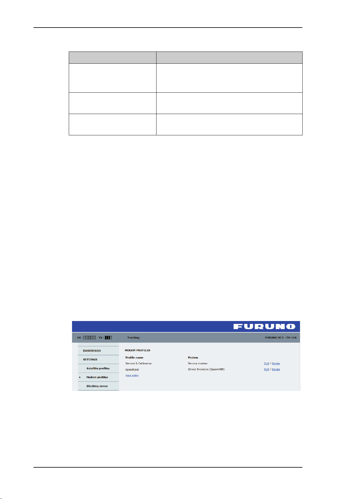
Configuration with the web interface
DUAL ANTENNA parameter Description
DUAL ANTENNA MASTER
or DUAL ANTENNA SLAVE
Status Shows the current status for the antenna (Master or
Show master dashboard or
Show slave dashboard
BUC TX information
The BUC TX information is displayed on the DASHBOARD in the section TX. BUC
TX indicates if the FV-110 has enabled the BUC or not. It can show On or Off. This
information is also shown in the display of the ACU as TX ON or TX OFF. The FV-110
shows BUC TX On when the following conditions are met:
• The FV-110 must sense the 10 MHz Tx reference signal from the connected VSAT
modem.
• The VSAT modem must have Rx lock.
• The antenna must point correctly to the satellite.
This is the Dashboard for the master or the slave
antenna. See also Dual antenna mode (optional) on
page 5-36.
Slave)
Click here to switch to the dashboard of the other
antenna in the dual antenna system.
Table 5-13: Web interface, DASHBOARD, dual antenna (option)
• The antenna must be in tracking mode.
5.3.2 Modem profiles and satellite profiles
Modem profiles
A modem profile contains all modem settings that are necessary for a successful
connection to the satellite. The data you have to fill in are provided by your VSAT service
and modem provider. You must add at least one modem profile.
Figure 5-16: Web interface: SETTINGS, Modem profiles — list (example)
On the page Modem profiles you create, edit or delete Modem profiles. The supported
Modem profiles are listed in the drop-down list Modem.
5-22
Page 85

Configuration with the web interface
To add or edit a Modem profile, do as follows:
1. Go to SETTINGS > Modem profiles and click New entry or Edit. The supported
modem profiles are listed in the drop-down list Modem profile.
Figure 5-17: Web interface: SETTINGS, Modem profile – supported modems
2. Fill in a Modem profile name of your own choice.
3. Select one of the supported VSAT modems from the drop down list. Once you have
selected a VSAT modem, entry fields required for this VSAT modem are displayed.
Generic modem: If you have a modem that is not included in the list, select the generic
modem. This is mainly used for troubleshooting purposes.
4. Fill in or edit the data provided by your VSAT service provider.
The following configuration data may be needed by the modem:
Parameter Description
IP address Enter the IP address for the dual antenna master.
Port Enter the modem IP port number.
VSAT modem root password iDirect serial login. Default: P@55w0rd!
VSAT modem user password iDirect serial login. Default: iDirect
Baud rate Select the baud rate for the modem communication or
modem GPS input.
GPS output Disable GPS output or select the appropriate baud rate.
10 MHz reference Select the 10MHz reference source for the BUC/LNBs.
Recommended settings:
VMU-TX: STM Satlink 2900, Gilat SkyEdge II,
COMTECH
ACU Internal: iDirect modems, service modem,
InmarsatG5
RSSI lock type Select None (no RX lock), High (positive voltage) or
Low (negative voltage)
RSSI lock level Enter the voltage level for the modem RX lock signal.
Range: 0 - 14000 mV (-14VDC to +14VDC)
Table 5-14: Modem configuration data
5-23
Page 86

Configuration with the web interface
Important
Note
The FV-110 can work either using the Rx or Tx 10 MHz reference signals
provided by the modem or using its own built-in 10 MHz reference signal. It
is recommended to use the Tx 10 MHz reference signal from the modem.
For modems communicating via Ethernet: Make sure that you have entered the
correct IP address also for the LAN connector that is used for the modem, see To
configure the LAN network on page 5-29.
5. Click Apply to add the new profile to the list of VSAT modem profiles or to accept the
edits.
For a generic modem you enter all parameters in the satellite profile.
Satellite profiles
On the page Satellite profiles you add, edit and delete satellite profiles. A satellite profile
contains all settings that are necessary for a successful connection to the satellite,
including a VSAT modem profile. Most of the data you have to fill in are provided by
your VSAT service provider. Each satellite profile has one assigned modem profile. You
must activate one satellite profile. You must activate one satellite profile.
Figure 5-18: Satellite profile for generic modem
You must add at least one VSAT modem profile before you can add a satellite
profile. See Modem profiles on page 5-22.
5-24
Page 87

Configuration with the web interface
Note
Figure 5-19: Web interface: SETTINGS - list of satellite profiles (example)
Each satellite profile has one assigned VSAT modem profile.
To add or edit a satellite profile, do as follows:
1. Go to SETTINGS or Satellite profiles and click Edit or New entry.
Figure 5-20: Web interface: SETTINGS, Satellite profiles — new entry (example)
2. Enter or edit the Satellite profile name.
It is helpful to assign a name containing the location where the Satellite
profile is to be used (e.g. Gulf of Mexico or North Sea) and possibly the
provider.
3. Select a VSAT modem profile. The page automatically displays the parameters
available for the selected VSAT modem profile.
For instruction how to add a VSAT modem profile see Modem profiles on page 5-22.
4. Enter the data for the satellite that you want to use. For satellite data see DVB-S
satellites on page E-1 or www.lyngsat.com.
5. Polarisation skew: See documents from VSAT provider.
5-25
Page 88
Configuration with the web interface
6. At Elevation cutoff enter the minimum elevation angle for the antenna to function in
accordance with ETSI (ETSI EN 302 340) and FCC (FCC §25.205) regulations.
• ETSI (ETSI EN 302 340): The minimum elevation angle depends on the Tx
bandwidth and the nominal power of the VSAT modem, see the table below.
Bandwidth Nominal VSAT modem power
22 dBm-20 dBm-18 dBm-16 dBm-14 dB
12 dBm-10 dBm
-8 dBm -6 dBm
m
a
GHz
63.4
dBm
65.4
dBm
67.4
dBm
69.4
dBm
71.4
dBm
73.4
dBm
75.4
dBm
77.4
dBm
79.4
dBm
64 kHz 3° 4° 4° 5° 6° 7° 8° 10° 12°
128 kHz 3° 4° 4° 5° 6° 7° 8° 10° 12°
256 kHz 3° 4° 4° 5° 6° 7° 8° 10° 12°
512 kHz 3° 4° 4° 5° 6° 7° 8° 10° 12°
1024 kHz 3° 4° 4° 5° 6° 7° 8° 10° 12°
2048 kHz 3° 3° 3° 4° 5° 5° 6° 8° 9°
4096 kHz 3° 3° 3° 3° 4° 4° 5° 6° 7°
8192 kHz 3° 3° 3° 3° 3° 3° 4° 5° 5°
16384kHz3°3°3°3°3°3°3°4°4°
32768kHz3°3°3°3°3°3°3°3°3°
Table 5-15: FV-110: Elevation cutoff (in degrees) versus VSAT modem bandwidth and power
a. Eirp = Fixed system gain 44 dB + antenna gain @ 14.25 GHz 41.4 dB + modem power
• FCC (FCC §25.205): 5 degrees
7. Click Apply to save the settings for the satellite profile.
5-26
Page 89

5.3.3 To set up blocking zones (RX and TX)
On this page you define blocking zones, i.e. NO TX and RX zones, enter azimuth values
and elevation angles for each blocking zone. You must select Active to enable a blocking
zone.
Configuration with the web interface
Figure 5-21: Web interface: SETTINGS, Blocking zones — azimuth and elevation
To define and set a blocking zone, do as follows:
1. Select SETTINGS > Blocking zones.
2. Select Active to enable the blocking zone.
5-27
Page 90

Configuration with the web interface
Important
3. Azimuth: Enter start and stop azimuth value in degrees for the blocking zone. Values
allowed: 0 to 360 degrees. Enter clockwise.
Figure 5-22: Blocking zone, example: 315 - 45 degrees
Figure 5-23: Blocking zone, example: 45 - 315 degrees
4. Elevation: Enter the start and stop elevation angle for the blocking zone. If you enter
nothing, there will be no blocking zone. Values allowed: -90 to 90 degrees.
You must enter 2 different elevation angles to have an active blocking zone.
5. Select No TX for zones if you don’t want the system to transmit.
If not selected, the system also transmits when pointing through areas with blocking
objects. The VSAT modem will shut off for TX if no signal is received.
6. Click Apply to save the blocking zones.
5-28
Page 91

5.3.4 To configure the LAN network
Important
You can enter a host name. The host name helps identifying the FV-110 system when
sending e-mail reports. The ACU has four 10/100 Mbit Ethernet ports labelled LAN port
1, 2, 3 and 4. The ports are divided in three groups, each group operating in its own
network. You can setup DNS and Gateway.
To configure the LAN network go to SETTINGS > Network.
Configuration with the web interface
Figure 5-24: Web interface: SETTINGS, Network (default settings)
Make sure that the 3 networks do not use IP address ranges that overlap.
5-29
Page 92
Configuration with the web interface
Sections Preferred use
NETWORK
Host name
LAN Port 1 + 2 LAN port 1 and 2 are switched, i.e. they share the same IP address
LAN Port 3 LAN port 3 is dedicated as the service port. By default this port has
LAN Port 4 LAN port 4 can be used for connection to the LAN of the vessel or
The host name is used for identifying the ACU in local networks and
in e-mail reports. The default host name is acu. You can change the
name. Letters (a-z), digits (0-9) and hyphen (-) are allowed as legal
characters.
Note: The host name must start with a letter.
and operate on the same network. This network is usually connected
to the VSAT Modem Unit.
LAN port 1 can be set to static IP (default), DHCP client or DHCP
server.
the IP address 192.168.0.1; the current value can be displayed in the
ACU display. In a 19” rack mount it is recommended to connect
LAN port 3 to the front port (via rear connector, see the figure ACU
connector panel — overview on page 3-1), for access to the service
port from the rack front.
LAN port 3 can be set to static IP, DHCP client or DHCP server
(default).
other general purpose.
LAN port 4 can be set to static IP, DHCP client (default) or DHCP
server.
Static IP or DHCP Client
If you select DHCP client the network IP address and sub-net mask must be provided by
a DHCP server on that network.
If you select Static IP address you must specify a unique IP address and a sub-net mask.
DHCP Server Settings.
On LAN ports 1,3 and 4 you can choose to run a DHCP server. Select the check box
DHCP Server. The DHCP server settings are only displayed and can be selected when
the port mode is set to Static IP, otherwise the DHCP server settings are not shown.
The DHCP start and end addresses must be on the same network as the port's static IP.
DNS setup
If you have access to a Domain Name Server (DNS) you can specify the address of the email server by using the server name instead of its IP address. This can be used in
Outgoing mail server in E-mail setup on page 5-31.
You may statically specify the address of one or two DNS. Select the DNS source as static
and fill in IP address or addresses. Alternatively, if your DHCP server can provide a DNS
address and you have selected DHCP client above, then select the same LAN as your
DNS source.
Table 5-16: Setup of LAN connectors
5-30
Page 93
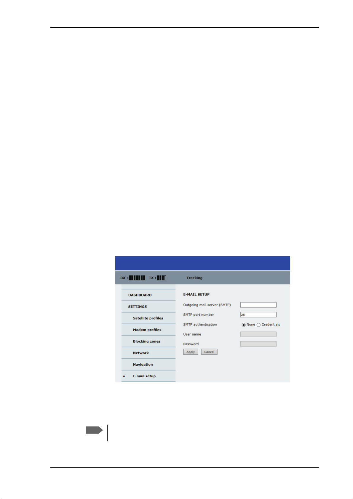
Gateway setup
Note
If the ACU needs to communicate with network units outside the specified sub-nets, you
must specify a default gateway (typically a router).
The default gateway can be set as a static IP address. Then set the default gateway source
to static and enter the IP address of the default gateway. To remove the default gateway
set it to 0.0.0.0.
Alternatively, if your DHCP server is able to provide a default gateway address and you
have selected DHCP client above, then select the same LAN as your default gateway
source.
Zeroconf Settings
On LAN ports 1,3 and 4 you can choose to add a zeroconf address in the network
(169.254.0.0).This zeroconf address will be in addition to the existing static or DHCP IP
address. One port at a time can be enabled.
Zeroconf allows devices to connect to a network automatically.
Configuration with the web interface
5.3.5 E-mail setup
To be able to send diagnostics and statistics reports using e-mail you must set up a couple
of parameters. Contact your IT department for the specific data.
To configure the e-mail setup, do the following:
1. Go to SETTINGS > E-mail setup.
Figure 5-25: Web interface: SETTINGS, E-mail setup (example)
2. Enter the data for Outgoing mail server (SMTP), SMTP port number, SMTP
authentication, User name and password. This data is typically provided by your IT
department.
You must set Outgoing mail server to an IP address if DNS has not been set up
in DNS setup in To configure the LAN network on page 5-29.
5-31
Page 94

Configuration with the web interface
5.3.6 Reports, syslog and SNMP traps
The antenna can send the following reports and messages:
• Diagnostics report
• Statistics report
• Remote syslog
• SNMP traps
Diagnostics report
You can send automatically generated diagnostic reports at fixed intervals. The diagnostic
report contains information from the ADU and ACU that are relevant for the service
personnel during troubleshooting. The report contains data for the selected download
intervals.
To set up sending a statistics report, do as follows:
1. Select SETTINGS > Reporting.
2. In the section DIAGNOSTICS REPORT enter the following:
3. Click Apply.
You can generate and send the diagnostic report at any time by clicking Send now. You
can also download a diagnostics report directly to your computer, go to the page
HELPDESK and click Download. For more details see To download diagnostic and
statistics reports on page 7-2.
When getting the log data between the ACU and the modem, select the check box for
Modem on the HELPDESK > Support page. The ACU-modem communication log is
added to the diagnostics report.
Note: Be aware that ACU-modem communication will fill up the log very quickly as
status commands are sent very often.
Statistics report
FV-110 can send a statistics report at fixed intervals. This report contains historical
information from the FV-110 of up to 1 month. It is sent as a zipped attachment to an email. The file format is a comma separated value file (csv). The report can then be
processed in spreadsheet applications, e.g. Microsoft Excel.
• E-mail sender.
• E-mail recipients (comma separated).
• Send interval: Select e-mail disabled, day (default, 2-minute samples), week
(hourly samples) or month (hourly samples).
5-32
To set up sending a statistics report, do as follows:
1. Configure e-mail first, see E-mail setup on page 5-31.
2. Go to SETTINGS > Reports.
3. In the section STATISTICS REPORT enter the following:
• Email sender.
• Email recipients (comma separated).
Page 95

Configuration with the web interface
• Send interval: Select disabled, day (default) with 2-minute samples, week with
hourly samples or month with hourly samples. The report contains statistics data
for the selected intervals.
4. Click Apply.
You can also send the report at any time by clicking Send now. Use Send now to validate
the e-mail setup. See also Download of a diagnostic report or a statistics report on
page 7-2.
The following parameters are recorded in the statistics report:
Parameter recorded Description
Hostname Host name, entered in the web interface on the page SETTINGS
> Network.
ACU SN ACU serial number
ADU SN ADU serial number
SW ver. Software version
System FV-110
Table 5-17: Statistics report, header record
Parameter recorded Description
UTC. (s)
UTC in seconds and date format for the data set.
UTC (YYYY-MM-DD hh:mm)
RSSI.Av
RSSI.Max
Received signal strength (average, maximum and
minimum value) for the sampling interval.
RSSI.Min
POS.Lat (degree)
POS.Long (degree)
POS.Valid
Latitude value of position.
Longitude value of position.
Fix = valid position, No Fix = invalid position.
NAV.Speed (m/s) Navigation speed
Heading.Samp (degree)
Heading.Max (degree)
Heading.Min (degree)
Ship’s heading (sample, maximum and minimum
value, range) for the sampling interval. See Figure 526: Statistics — how to read data for a range.
Heading.Range (+/-degree)
Antenna.Azi (degree)
Antenna.Azi Max (degree)
Antenna.Azi Min (degree)
Antenna.Azi Range (+/-degree)
Current antenna azimuth (sample, maximum and
minimum value, range) for the sampling interval.
See Figure 5-26: Statistics — how to read data for a
range.
Antenna.Ele (+/-degree)
Antenna.Ele Max (+/-degree)
Antenna.Ele Min (+/-degree)
Table 5-18: Parameters recorded in a statistics report
Current antenna elevation (sample, maximum and
minimum value) for the sampling interval.
5-33
Page 96
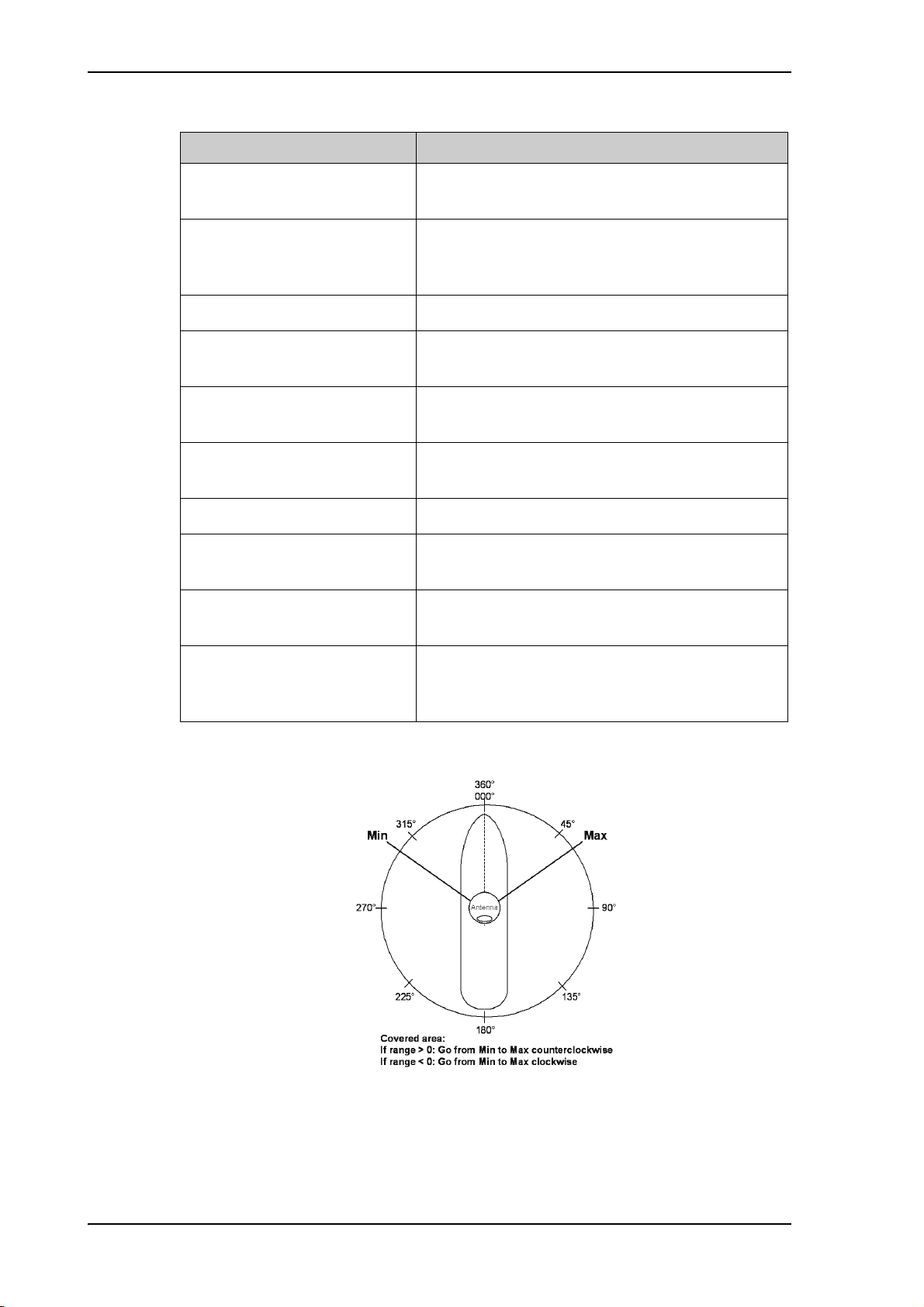
Configuration with the web interface
Parameter recorded Description
Vsat.rx_lo_freq (GHz)
Vsat.tx_lo_freq (GHz)
Tracking.rf freq (GHz)
Tracking.type
Rx frequency of VSAT modem for this record.
Tx frequency of VSAT modem for this record.
Tracking RF frequency for this record.
Narrow filter, DVB-S2 decoder and VSAT modem
RSSI.
Sat.long (degree) Longitude position of the satellite.
Carrier rf.rx (GHz)
Carrier rf.tx (GHz)
Pol.rx
Rx frequency of carrier for this record.
Tx frequency of carrier for this record.
Current Rx and Tx polarisation modes
Pol.tx
Rx Lock (%)
Logon (%)
Rx locked and logon time, in percent, for the
sampling interval.
Pos Ok (%) Valid position, in percent of the sampling interval.
VMU Connection (%) Link with VSAT modem, in percent of the sampling
interval.
Blocking (%) Ship in blocking zone, in percent of the sampling
interval.
DualAntenna.mode
DualAntenna.logon_remote (%)
DualAntenna.active (%)
Table 5-18: Parameters recorded in a statistics report (Continued)
Figure 5-26: Statistics — how to read data for a range
Shows the current mode and the time active and
remote logon.
5-34
Page 97

Processing the statistics report in a spreadsheet application
The statistics report is in a data format that can be imported into spreadsheet applications,
e.g. Microsoft Excel, for further processing.
1. Save the zipped file to your computer and extract the text file. The file name contains
the identification of the system (example: adu-acu3_stat_20111021110901_day.csv).
2. Open the spreadsheet application, for example Microsoft Excel. On the tab Data click
the tab Import from text. Import the unzipped text file and follow the instructions in
the wizard. When asked about the delimiter, select ‘comma’.
The following figure shows an example of a statistics report in MS Excel 2007.
Remote syslog
You can set up the antenna to send each syslog message to a syslog server to advise the
system administrator of the current status of the antenna.
To set up sending syslog messages to a syslog server, do as follows:
Configuration with the web interface
SNMP traps
1. Select SETTINGS > Reporting.
2. In the section Remote syslog select On to enable remote syslog (default: Off).
3. Enter the IP address of the syslog server to which the syslog messages will be sent.
4. Click Apply.
SNMP traps, or notifications, are network packets which advise the system administrator
about significant events in the antenna, e.g. alarms and system error messages. They are
generated by the antenna and can be sent automatically to an SNMP trap
receiver/manager. The event time is UTC time.
To set up reporting SNMP traps to an SNMP server, do as follows:
1. Select SETTINGS > Reporting.
2. In the section SNMP traps select On to enable sending of SNMP traps (default: Off).
3. Enter the IP address of the SNMP trap receiver/manager to which the SNMP traps will
be sent.
4. Enter the Community name. This is the name of the SNMP trap receiver/manager.
This is needed for authentication of the SNMP trap request.
5. Click Apply.
5-35
Page 98
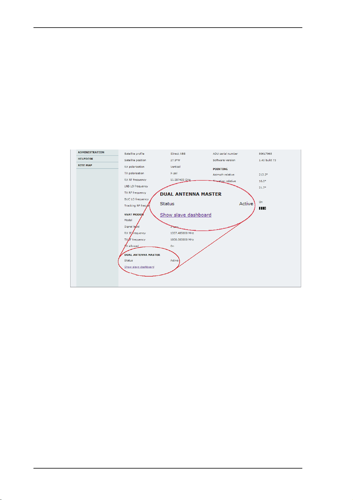
Configuration with the web interface
5.3.7 Dual antenna mode (optional)
The following tasks must be taken care of when setting up a dual-antenna system:
• To configure the Master ACU
• To configure the Slave ACU
• Blocking zone setup for dual antenna setup
• Line up and commissioning for dual antenna setup
At the bottom of the DASHBOARD of the web interface there is a section where you can
switch over to the other ACU dashboard. Next to Status you can see whether the current
ACU is active or not.
Figure 5-27: Dual-antenna mode, link on DASHBOARD
The dual-antenna system switches between the 2 antennas in the following scenarios:
• When in a programmed blocking zone.
• When the signal is blocked for more than 2 minutes.
• ADU is malfunctioning.
In the statistics report you can get more detailed information on the dual-antenna mode,
see also Table 5-18 on page 5-33.
5-36
Page 99
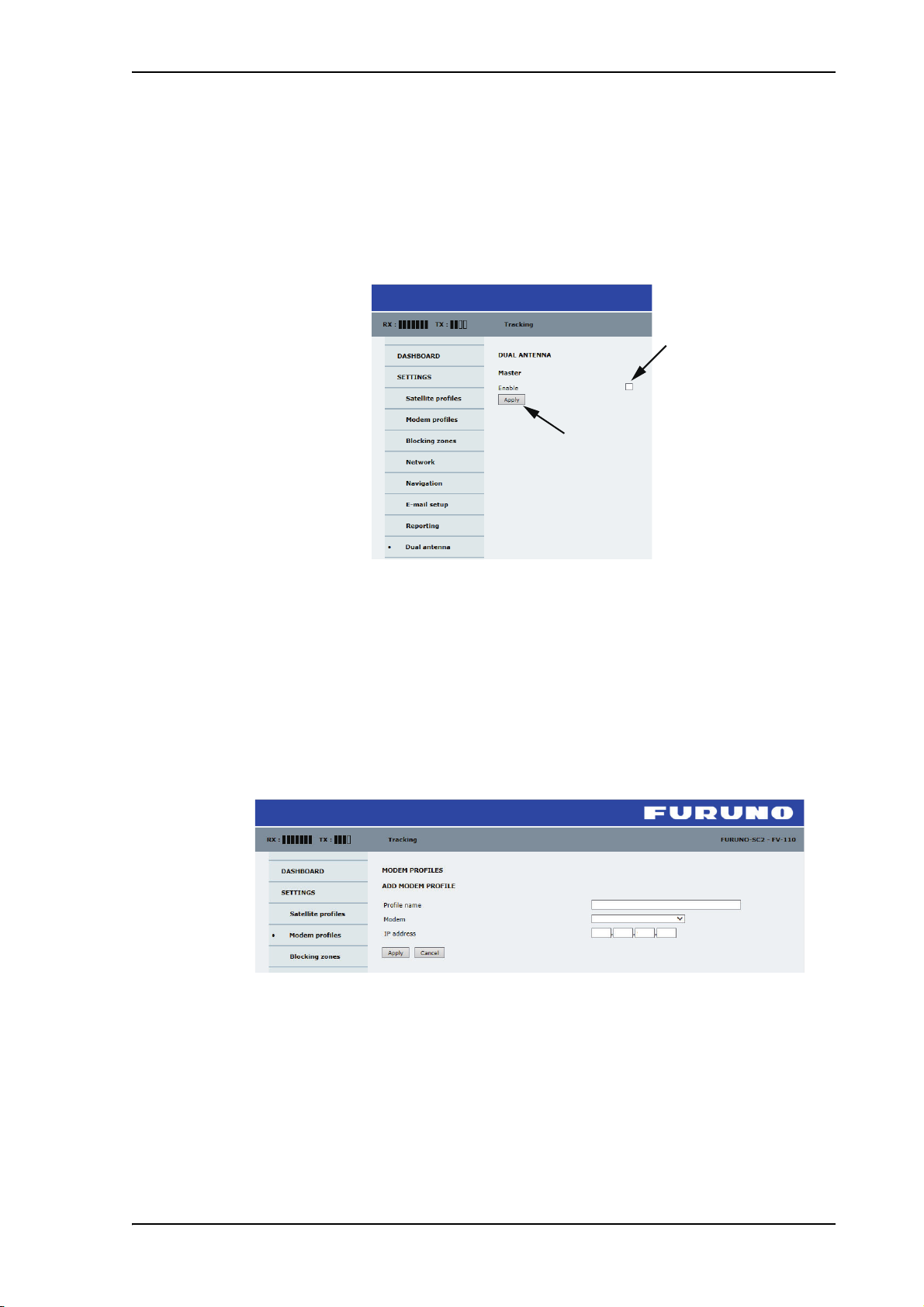
To configure the Master ACU
Dual Antenna Master
Dual Antenna Master
10 110 8 74
The Master ACU is configured exactly the same way as a stand-alone FV-110 system
with satellite profiles and VSAT modem profiles. Do as follows:
1. Go to SETTINGS > Dual antenna.
2. Select Enable and click Apply.
Configuration with the web interface
The FV-110 is now ready to act as Master ACU.
To configure the Slave ACU
The Slave ACU is configured to use the Master ACU as VSAT modem profile. The
VSAT modem profile must point to the IP address of the Master ACU, that is the IP
address of the LAN port at which the Master/Slave communication cable is connected.
1. Add a specific Modem profile for dual-antenna mode, go to SETTINGS > Modem
profiles > New entry.
2. Enter the profile name, for example Dual Antenna Master.
Figure 5-28: Enabling dual-antenna mode in Master ACU
Figure 5-29: Dual-antenna mode, add Slave modem profile
3. As VSAT modem select Dual Antenna Master.
4. IP address: this is the IP address of the LAN connector at the Master ACU. See To
configure the LAN network on page 5-29.
5. Click Apply.
5-37
Page 100
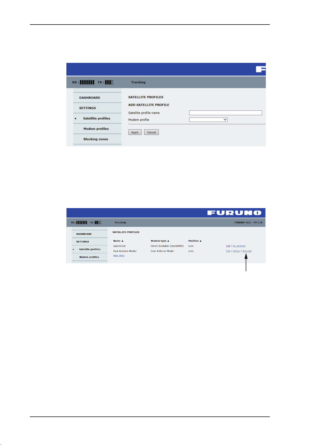
Configuration with the web interface
Dual Antenna Master
Dual Antenna Master
6. Add a satellite profile that uses the VSAT modem Dual Antenna Master, go to
SETTINGS > Satellite profiles > New entry.
Figure 5-30: Dual-antenna mode, add Slave satellite profile
7. Enter the satellite profile name, for example: Dual Antenna Master.
8. As VSAT modem profile select Dual Antenna Master.
9. Click Apply.
10.Go to SETTINGS > Satellite profiles and activate the satellite profile Dual Antenna
Master.
Figure 5-31: Dual-antenna mode, Activate
5-38
 Loading...