

Page 1

OPERATOR'S MANUAL
DOPPLER SONAR
MODEL
DS-60
www.furuno.co.jp
Page 2

9-52 Ashihara-cho,
*
00017233410
**00017233410
*
Nishinomiya, 662-8580, JAPAN
Telephone : +81-(0)798-65-2111
Fax :+81-(0)798-65-4200
The paper used in this manual
is elemental chlorine free.
・FURUNO Authorized Distributor/Dealer
All rights reserved.
Pub. No. OME-72640-A7
(DAMI ) DS-60
Printed in Japan
A : MAR 2010
.
A7 : APR . 25, 2011
*00017233410**00017233410*
* 0 0 0 1 7 2 3 3 4 1 0 *
Page 3
IMPORTANT NOTICES
General
• This manual has been authored with simplified grammar, to meet the needs of international users.
• The operator of this equipment must read and follow the descriptions in this manual. Wrong operation or maintenance can cancel the warranty or cause injury.
• Do not copy any part of this manual without written permission from FURUNO.
• If this manual is lost or worn, contact your dealer about replacement.
• The contents of this manual and equipment specifications can change without notice.
• The example screens (or illustrations) shown in this manual can be different from the screens
you see on your display. The screens you see depend on your system configuration and equipment settings.
• Save this manual for future reference.
• Any modification of the equipment (including software) by persons not authorized by FURUNO
will cancel the warranty.
• All brand and product names are trademarks, registered trademarks or service marks of their
respective holders.
How to discard this product
Discard this product according to local regulations for the disposal of industrial waste. For disposal
in the USA, see the homepage of the Electronics Industries Alliance (http://www.eiae.org/) for the
correct method of disposal.
How to discard a used battery
Some FURUNO products have a battery(ies). To see if your product has a battery, see the chapter
on Maintenance. Follow the instructions below if a battery is used. Tape the + and - terminals of
battery before disposal to prevent fire, heat generation caused by short circuit..
In the European Union
The crossed-out trash can symbol indicates that all types of batteries
must not be discarded in standard trash, or at a trash site. Take the
used batteries to a battery collection site according to your national
legislation and the Batteries Directive 2006/66/EU.
In the USA
The Mobius loop symbol (three chasing arrows) indicates that Ni-Cd
and lead-acid rechargeable batteries must be recycled. Take the used
batteries to a battery collection site according to local laws.
Ni-Cd Pb
In the other countries
Cd
There are no international standards for the battery recycle symbol. The number of symbols can
increase when the other countries make their own recycle symbols in the future.
i
Page 4
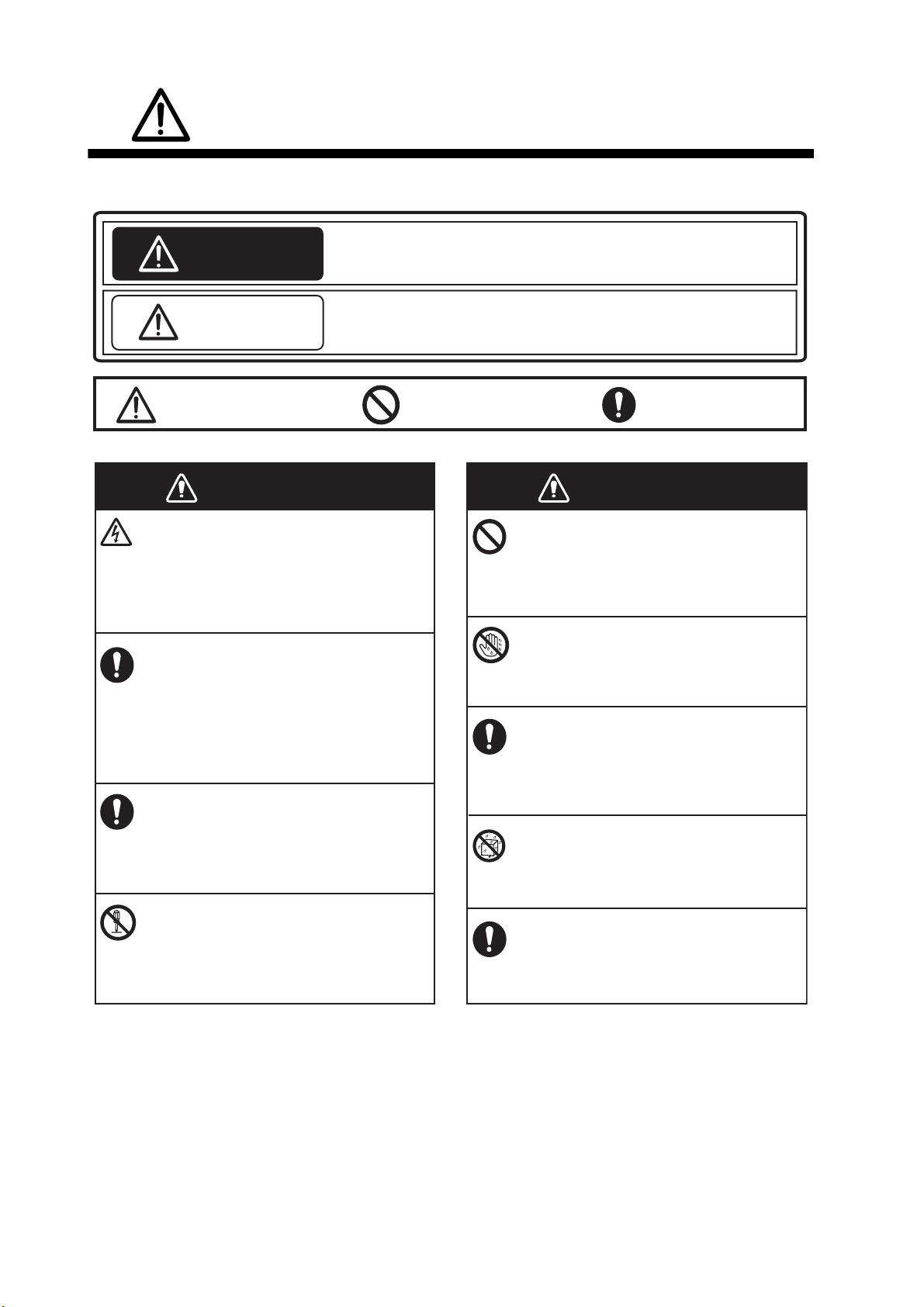
SAFETY INSTRUCTIONS
Please read these safety instructions before you operate the equipment.
Indicates a condition that can cause death or serious injury if
WARNING
CAUTION
Warning, Caution
not avoided.
Indicates a condition that can cause minor or moderate injury if
not avoided.
Prohibitive Action
Mandatory Action
WARNING
Do not open the equipment.
This equipment uses high voltage that can
cause electrical shock.
Only qualified persons can work inside
the equipment.
Turn off power at the switchboard if
something is dropped inside the
equipment or water leaks into the
equipment.
Fire or electrical shock can result if the
power remains on.
Turn off the power at the switchboard if
the equipment is emitting smoke or fire.
Fire or electrical shock can result if the
power remains on.
Do not disassemble or modify the
equipment.
WARNING
Do not put liquid-filled containers on
or near the equipment.
Fire or electrical shock can result if a
liquid spills into the equipment.
Do not operate the equipment with
wet hands.
Fire or electrical shock can result.
If you feel the equipment is abnormal
or is giving off strange noises, turn
off the power at the switchboard
immediately. Contact a FURUNO agent
or dealer for advice.
Do not allow rain or water splash to
get into the equipment.
Fire or electrical shock can result.
Use the correct fuse.
Fire, electrical shock or bodily injury
can result.
Use of a wrong fuse can cause bodily
injury or fire.
ii
Page 5

SAFETY INSTRUCTIONS
CAUTION
If an LCD-type display is used, handle
the display with care.
The panel is made of glass which, if broken,
can cause injury.
Do not paint the transducer .
Paint causes a large drop in sensitivity.
Do not power the equipment when the
transducer is in air.
The transducer can become damaged.
Remove marine life from the face of the
transducer when the ship is dry-docked.
Marine life can affect sensitivity.
CAUTION
If the optional rate gyro is installed, power
the system when the ship is stationary or
is traveling in a straight line.
The point of reference for the rate gyro is
determined when the system is powered. If
the ship is turning at that time, the point of
reference will be wrong and the gyro
indication in error. When the rate gyro goes
off (power outage, etc.), make sure the ship is
stationary or traveling in a straight line before
turning on the rate gyro.
Warning Label
Warning label(s) is(are) attached to the equipment.
Do not remove the label(s). If a label is missing or
damaged, contact a FURUNO agent or dealer
about replacement.
WARNING
To avoid electrical shock, do not
remove cover. No user-serviceable
parts inside.
Name: Warning Label (1)
Type: 86-003-1011-3
Code No.: 100-236-233-10
iii
Page 6

TABLE OF CONTENTS
FOREWORD ...................................................................................................................vi
SYSTEM CONFIGURATION ........................................................................................viii
1. INTRODUCTION ....................................................................................................1-1
1.1 Controls......................................................................................................................1-1
1.1.1 Display Unit DS-600.......................................................................................1-1
1.1.2 Remote Controller RD-501 (option) ...............................................................1-3
1.1.3 Dimmer Controller RD-502 (option) ...............................................................1-3
1.2 How to Turn the Power On and Off............................................................................1-4
1.3 How to Adjust the Screen Brilliance ........................................................................... 1-5
1.4 How to Select a Display ............................................................................................. 1-5
1.5 How to Select a Tracking Mode ................................................................................. 1-6
1.6 How to Change Units of Measurement ...................................................................... 1-7
1.7 How to Reset the Trip Distance Indication ................................................................. 1-8
1.8 How to Select Daytime and Nighttime Displays ......................................................... 1-9
1.9 General Menu Operation............................................................................................ 1-9
2. NAVIGATION DATA DISPLAY..............................................................................2-1
2.1 Navigation Data Display Overview.............................................................................2-1
2.1.1 Description of indications ............................................................................... 2-2
2.2 How to Set Navigation Data ....................................................................................... 2-3
2.2.1 Time ............................................................................................................... 2-3
2.2.2 Time format.................................................................................................... 2-4
2.2.3 Depth measurement reference ...................................................................... 2-5
2.2.4 Current direction............................................................................................. 2-5
2.2.5 Wind angle ..................................................................................................... 2-7
2.2.6 Wind averaging time ...................................................................................... 2-8
2.2.7 ROT sensor.................................................................................................... 2-8
2.3 How to Set the Speed Alarm......................................................................................2-9
3. BERTHING DISPLAY ............................................................................................3-1
3.1 Berthing Display Overview ......................................................................................... 3-1
3.2 Display Range............................................................................................................3-2
3.2.1 How to select a range .................................................................................... 3-2
3.2.2 How to pre-set ranges.................................................................................... 3-2
3.3 Track .......................................................................................................................... 3-3
3.3.1 Types of tracks............................................................................................... 3-3
3.3.2 How to select the type of track to display.......................................................3-4
3.3.3 How to select the past track format................................................................3-5
3.3.4 How to select the predicted track plot interval................................................ 3-5
3.4 How to Select Vector Time......................................................................................... 3-6
3.5 How to Show, Hide Navigation Data and 3-axis Speed Data ....................................3-7
3.6 Berthing Line .............................................................................................................. 3-8
3.6.1 How to create a berthing line .........................................................................3-8
3.6.2 How to share berthing lines with sub display units....................................... 3-12
3.6.3 How to delete a berthing line........................................................................ 3-13
4. SPEED GRAPHIC DISPLAY .................................................................................4-1
4.1 Speed Graphic Indications ......................................................................................... 4-1
4.2 How to Activate the Speed Graphic ........................................................................... 4-2
4.3 How to Select the Display Format for the Speed Graphic.......................................... 4-3
4.4 How to Change the Speed Graphic Format ............................................................... 4-5
iv
Page 7

TABLE OF CONTENTS
5. OTHER OPERATIONS .......................................................................................... 5-1
5.1 How to Set the Displays .............................................................................................5-1
5.2 Key Beep On/Off ........................................................................................................5-4
5.3 How to Adjust Key Dimmer.........................................................................................5-4
5.4 How to Select Direction Symbol Format.....................................................................5-5
5.5 How to Select the Location for the Direction Symbols................................................5-6
5.6 Total Distance Run.....................................................................................................5-7
5.6.1 How to reset total distance run.......................................................................5-7
5.6.2 How to set total distance run ..........................................................................5-8
5.7 System Parameters....................................................................................................5-9
6. MAINTENANCE,
TROUBLESHOOTING...........................................................................................6-1
6.1 Maintenance...............................................................................................................6-1
6.2 Consumable Parts......................................................................................................6-2
6.2.1 Fuse replacement...........................................................................................6-2
6.2.2 Product life .....................................................................................................6-2
6.3 Troubleshooting..........................................................................................................6-3
6.4 Error Messages ..........................................................................................................6-4
6.5 Diagnostics.................................................................................................................6-5
6.5.1 System test.....................................................................................................6-5
6.5.2 Display unit test ..............................................................................................6-9
6.5.3 LCD test .......................................................................................................6-10
6.6 TX Monitor................................................................................................................6-11
6.7 Echo Monitor ............................................................................................................6-12
6.8 How to Restore Initial Settings .................................................................................6-15
APPENDIX 1 MENU TREE .......................................................................................AP-1
APPENDIX 2 DIGITAL INTERFACE ........................................................................AP-3
APPENDIX 3 ABBREVIATIONS...............................................................................AP-9
APPENDIX 4 PARTS LIST, PARTS LOCATION ...................................................AP-12
SPCIFICATIONS ....................................................................................................... SP-1
INDEX ......................................................................................................................... IN-1
v
Page 8
FOREWORD
A Word to the Owner of the DS-60
Congratulations on your choice of the DS-60 Doppler Sonar. We are confident you will see why
the FURUNO name has become synonymous with quality and reliability.
For over 60 years FURUNO Electric Company has enjoyed an enviable reputation for innovative
and dependable marine electronics equipment. This dedication to excellence is furthered by our
extensive global network of agents and dealers.
Your equipment is designed and constructed to meet the rigorous demands of the marine environment. However, no machine can perform its intended function unless properly operated and
maintained. Please carefully read and follow the operation and maintenance procedures set forth
in this manual.
Thank you for considering and purchasing FURUNO.
Features
The DS-60 is a high precision Doppler Sonar designed for use on VLCC, LNG, LPG, container
ships, cargo ships, etc. The DS-60 measures speeds relative to ground and water in the fore, stern
and transverse directions. This arrangement provides for precision docking of tankers and the like
to loading and unloading facilities, as well as safe navigation in narrow channels and straits.
• Meets the requirements of IEC 61023 Ed 3.0, IEC 60945 Ed 4th.
• Measurement accuracy of ±0.01 m/s.
• Ground tracking from 1-200 m for accurate ground speed in coastal waters.
• Sub display units (max. 5) for display on the wing, etc.
vi
Page 9
Program Numbers
Unit, Program Number Date of Modification
DS-600
Starter 6652000-01.xx March 2010
Booter 6652001-02.xx March 2010
Main 6652002-02.xx March 2010
DS-610
Starter 6652100-01.xx March 2010
Booter 6652101-02.xx March 2010
Main 6652102-02.xx March 2010
FPGA 6652103-00.xx March 2010
DS-620
Starter 6652200-01.xx March 2010
FOREWORD
Booter 6652201-02.xx March 2010
Main 6652202-02.xx March 2010
FPGA1 6652203-00.xx March 2010
FPGA2 6652204-00.xx March 2010
RD-501, RD-502
2651009-01.xx August 2009
xx=minor change
vii
Page 10
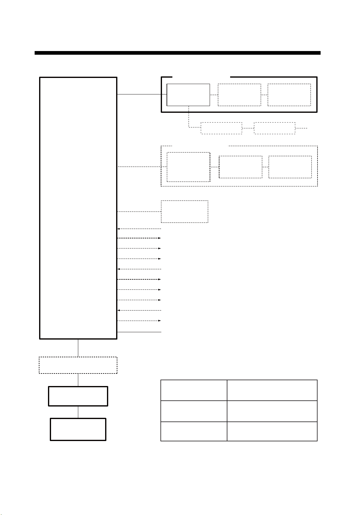
SYSTEM CONFIGURATION
MAIN DISPLAY UNIT
DISTRIBUTOR UNIT
DS-610
DS-600
DISPLAY
UNIT
SUB DISPLAY UNIT
DS-600 /
RD-50 / RD-20
DISPLAY
UNIT
RATE-OF-
TURN GYRO
DS-670
CONTROLLER
RD-50 / RD-20
CONTROLLER
Heading
Analog Meter Output x 2
Analog Current Output x 1
Analog Voltage Output x 1
IEC 61162 Input x 3
IEC 61162 Output x 5
Distance Run Pulse x 4
Alarm System
External KP
KP Output
100-240 VAC
RD-501
REMOTE
RD-501
REMOTE
RD-502
DIMMER
CONTROLLER
RD-50 / RD-20
RD-502
DIMMER
CONTROLLER
Max. 5
JUNCTION BOX
DS-640, DS-645A/B
TRANSCEIVER UNIT
TRANSDUCER
DS-630 or DS-631
viii
DS-620
Dashed lines indicate optional equipment.
Environmental category:
Protected from the
weather
Exposed to the weather
Protected from the
weather by waterproof
container
DS-600, DS-610, DS-620, DS-640,
DS-645A/B, DS-670, RD-501,
RD-502
DS-630, DS-631
DS-600 in Waterproof Box DS-605
Page 11
1. INTRODUCTION
This chapter provides the information necessary to get you started with the system.
The display unit has ten keys that respond immediately to your command. When you
operate a key, a single beep sounds. If you do not need the beep, you can deactivate
the beep from the menu.
Standards used in this manual
The control names are shown in bold face, for example, “DISP key”. Menu-related
items are in brackets, for example, [Key Beep].
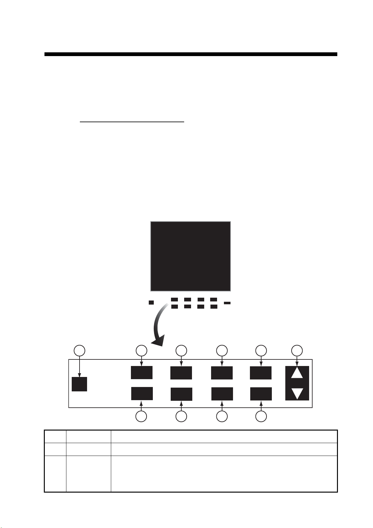
1.1 Controls
1.1.1 Display Unit DS-600
MENU
ALARM
UNITUNIT
1 2
PWR
DISP
TRKG
MODE
3
PWR
DISP
TRKG
MODE
RNG
4
UNIT
RNG
5
ACK
DAY
NT
ESC
BRILL
ENT
6
ALARM
ACK
DAY
DAY
NT
NT
7
No. Control Function
1 PWR Turn the power on and off.
2 DISP • Select a display.
• Close the menu and return to last-used display.
• In multiple data displays, select a data indication to change its unit of
measurement (with the UNIT key).
8
MENU
MENU
ESC
ESC
DAY
ENT
ENT
NT
9
10
BRILL
1-1
Page 12

1. INTRODUCTION
No. Control Function
3TRKG
MODE
4 UNIT Select the unit of measurement for speed, depth, distance, current (tide)
5 RNG Select the range in the berthing and echo monitor displays.
6 ALARM ACK Stop the audible alarm.
7 DAY/NT Select the daytime and nighttime displays alternately.
8 MENU/ESC • Open the menu.
9 ENT • Confirm an operation in menu operation.
• Main display unit: Select the tracking mode (water, ground, or auto) for
the measurement of ship’s speed.
• Sub display unit: Select the tracking mode to ground tracking or water
tracking when the tracking mode at the main display unit is ground tracking.
speed, wind speed, etc.
• Return control to the menu window without making any changes at the
menu options window.
• Select the item to change its unit of measurement in multiple data
displays.
• Close the menu when the menu window is active.
• Long-push to hide or show nav data and 3-axis speed data in the
berthing mode.
• Long-push to reset the trip distance on the displays that show trip
distance.
10 BRILL • Adjust the screen brilliance. T to decrease the brilliance, S to increase
the brilliance.
• Move the cursor in menu operation.
1-2
Page 13

1.1.2 Remote Controller RD-501 (option)
1. INTRODUCTION
2
1
DISP
REMOTE CONTROLLER
UNIT
RD-501
MODE
3
No. Control Function
1 DISP • Select a display.
• Close the menu and return to last-used display.
• In multiple data displays, select a data indication to change its unit of
measurement (with the UNIT key).
2 UNIT Select the unit of measurement for speed, depth, distance, current (tide)
speed, wind speed, etc.
3MODE • Main display unit: Select the tracking mode (ground, water, or auto) for
the measurement of ship speed.
• Sub display unit: Select the tracking mode to ground tracking or water
tracking when the tracking mode at the main display unit is ground tracking.
1.1.3 Dimmer Controller RD-502 (option)
2
1
No. Control Function
1 DAY/NT Select the daytime and nighttime displays alternately.
2 T, S Adjust the screen brilliance. T to decrease the brilliance, S to increase the
brilliance. To quickly increase or decrease the brilliance, press and hold the
related key.
DAY
NT
BRILL
DIMMER CONTROLLER
RD-502
1-3
Page 14
1. INTRODUCTION
1.2 How to Turn the Power On and Off
Press the PWR key to turn on the power.
The main display unit shows the serial numbers, program numbers and results of the
RAM and ROM checks (OK or NG) for the Display Unit DS-600, Distributor Unit DS610, and Transceiver Unit DS-620. The sub display unit shows its serial number, program number and results of the ROM and RAM check, "OK" or "NG" (No Good.) After
the program numbers appear and the test results are displayed, “Now calibrating...” is
displayed momentarily on the main display unit, the start-up screen is erased, then the
last-used display appears.
Note: If "NG" appears as the RAM or ROM check result, the equipment stops. Reset
the power to try to restore normal operation. If you cannot restore normal operation,
contact a FURUNO agent or dealer for instruction.
To turn off the power, press the PWR key.
Main display unit
Unit Name : DS-600
Serial No : -XXXX
Program No : 6652002-xx.xx
ROM : OK
RAM : OK
Unit Name : DS-610
Serial No : XXXX-XXXX
Program No : 6652102-xx.xx
ROM : OK
RAM : OK
Unit Name : DS-620
Serial No : XXXX-XXXX
Program No : 6652202-xx.xx
ROM : OK
RAM : OK
Unit Name : DS-600
Serial No : -XXXX
Program No : 6652002-xx.xx
ROM : OK
RAM : OK
Unit Name : DS-610
Serial No : XXXX-XXXX
Program No : 6652102-xx.xx
ROM : OK
RAM : OK
Unit Name : DS-620
Serial No : XXXX-XXXX
Program No : 6652202-xx.xx
ROM : OK
RAM : OK
Sub display unit
Unit Name : DS-600
Serial No : -XXXX
Program No : 6652002-xx.xx
ROM : OK
RAM : OK
Now calibrating...
1-4
Note: The screen refreshes slower in low ambient temperature.
Page 15
1.3 How to Adjust the Screen Brilliance
You can adjust the brilliance of the display screen from the display unit and the
Dimmer Controller, in 10 levels including off. Press S to increase the brilliance, or
press T to decrease the brilliance. To quickly change the brilliance, press and hold
related arrow.
If the Remote Display RD-50 (sub display unit) is connected to the display unit of the
DS-60 in a daisy chain, their brilliances are mutually adjusted when you adjust the brilliance from the DS-60.
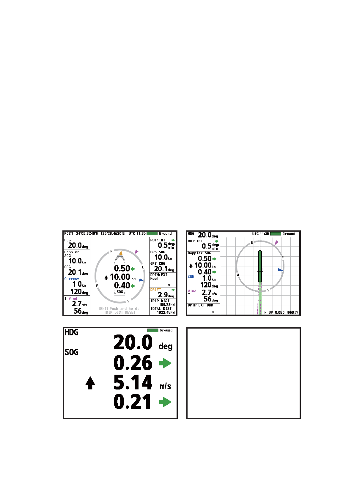
1.4 How to Select a Display
Press the DISP key to select a display. In the default arrangement there are four displays: navigation data, berthing (head-up), heading and speed, and trip distance and
total distance.
A maximum of seven displays are available, in full screen or two-way horizontal split
screen. Section 5.1 shows you to set the displays to meet your requirements.
1. INTRODUCTION
When a data is lost, hyphens; for example, “- -.-”, replace the lost data. When a data
is in error, its unit (kn, etc.) is shown in white characters on a red background. The
“normal” unit appears again when the data returns.
56.0
56.0
Navigation data display
Berthing display (head-up)
Heading, speed data display Trip distance, total distance run display
Default displays
1-5
Page 16
1. INTRODUCTION
1.5 How to Select a Tracking Mode
Press the TRKG MODE key (main display unit) or the MODE key (Remote Controller)
to select a tracking mode, among ground, water and auto. Select the mode according
to the depth and speed. The tracking mode indication, Ground, Water, or (Auto),
appears at the top-right corner.
The tracking mode monitor (bar) at the top of the display shows the history of tracking
modes for the past three minutes. The bar is updated every three seconds and scrolls
leftward. The color of the bar is green for ground tracking, blue for water tracking, and
background color when there is no echo input.
A
Tracking mode monitor ( )
(History of tracking mode in last 3 min.)
Green: ground tracking
Blue: water tracking
Background color: no echo
Description of tracking modes
Tracking mode
- Ground
- Water
- (Auto)
56.0
1-6
Ground: Measure and display a
speed relative to the sea bottom. The
depth from the keel must be 1-200 m
to use this mode.
Water: Measure and display a speed
relative to the watermass. The depth
from the keel must be at least three
meters to use this mode. However,
Water tracking speed
reference layer
Water tracking
speed
Ground
tracking
speed
(depth 1-200 m)
the accuracy is lower when the clearance is less than 40 m.
The reference layer can be set with
In the ground tracking mode, the bottom is
used as reference to calculate movement.
[Track Depth] on the [System menu].
See section 5.7.
Auto: Automatically selects ground tracking mode or water tracking mode according
to the depth. The water tracking mode is selected when the keel clearance is 200 m
or more. (Actual working depth in the ground tracking mode depends on the bottom
and water conditions, and the reflection properties for sonic pulses.)
Page 17

1.6 How to Change Units of Measurement
The UNIT key selects the unit of measurement for current (tide) speed, depth, distance, Doppler SOG and STW, GPS SOG, and wind speed.
Single data display
Press the UNIT key to select a unit of measurement.
Multiple data display
1. Press the UNIT key. A unit is highlighted in yellow.
In the example of the navigation data display shown below, the speed unit is highlighted.
1. INTRODUCTION
56.0
Highlight (yellow)
2. Press the DISP key to select the data for which to change its unit. (Use the MENU/
ESC key to reverse the selection order.)
3. Press the UNIT key to change the unit. See the table below for item and available
units.
Item Available units
Berthing display range meters/DIV (m/DIV), nautical miles/DIV (NM/DIV)
Current (tide) speed knots (kn), meters/second (m/s)
Distance kilometers (km), nautical miles (NM)
Depth fathoms (fm), feet (ft), meters (m)
Ground tracking (SOG)
Water tracking (STW)
kilometers/hour (km/h), knots (kn), meters/second (m/s)
Wind speed knots (kn), meters/second (m/s), miles/hour (mph)
To quit the unit selection, press the DISP or MENU/ESC key until the yellow highlight
disappears.
1-7
Page 18
1. INTRODUCTION
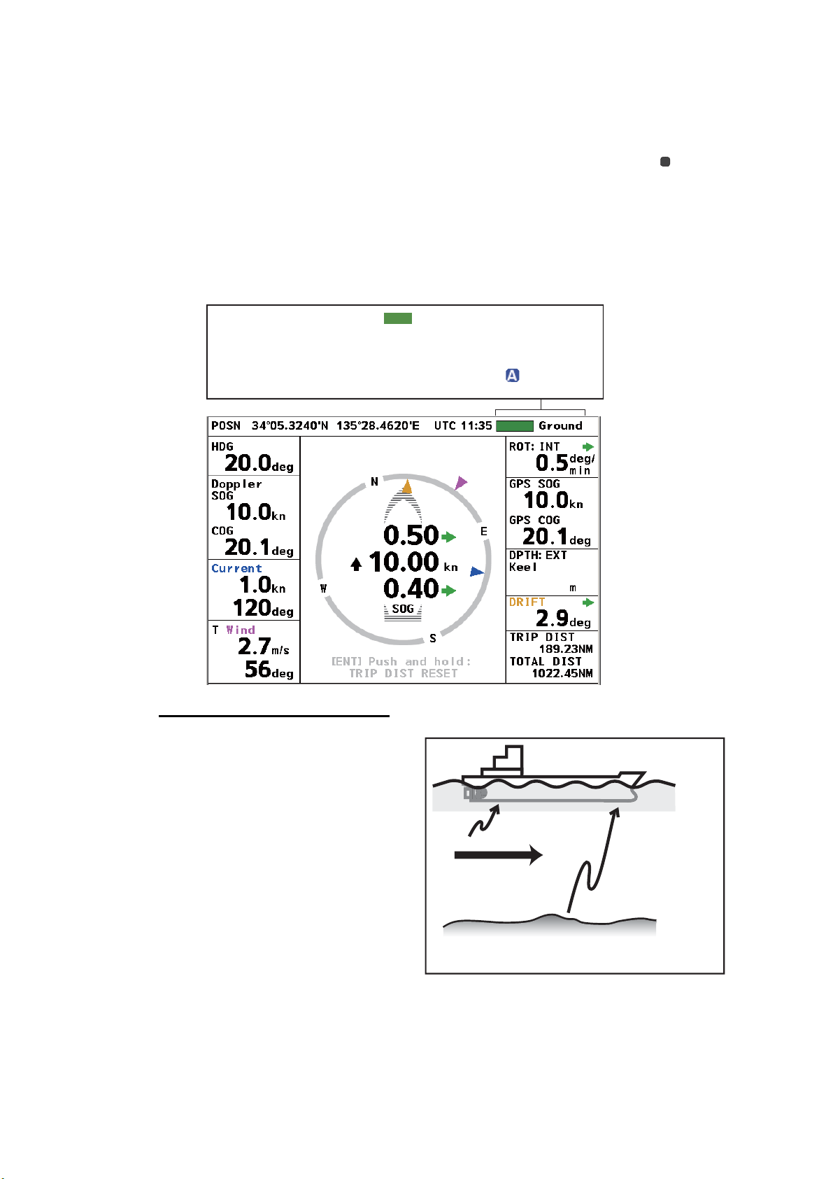
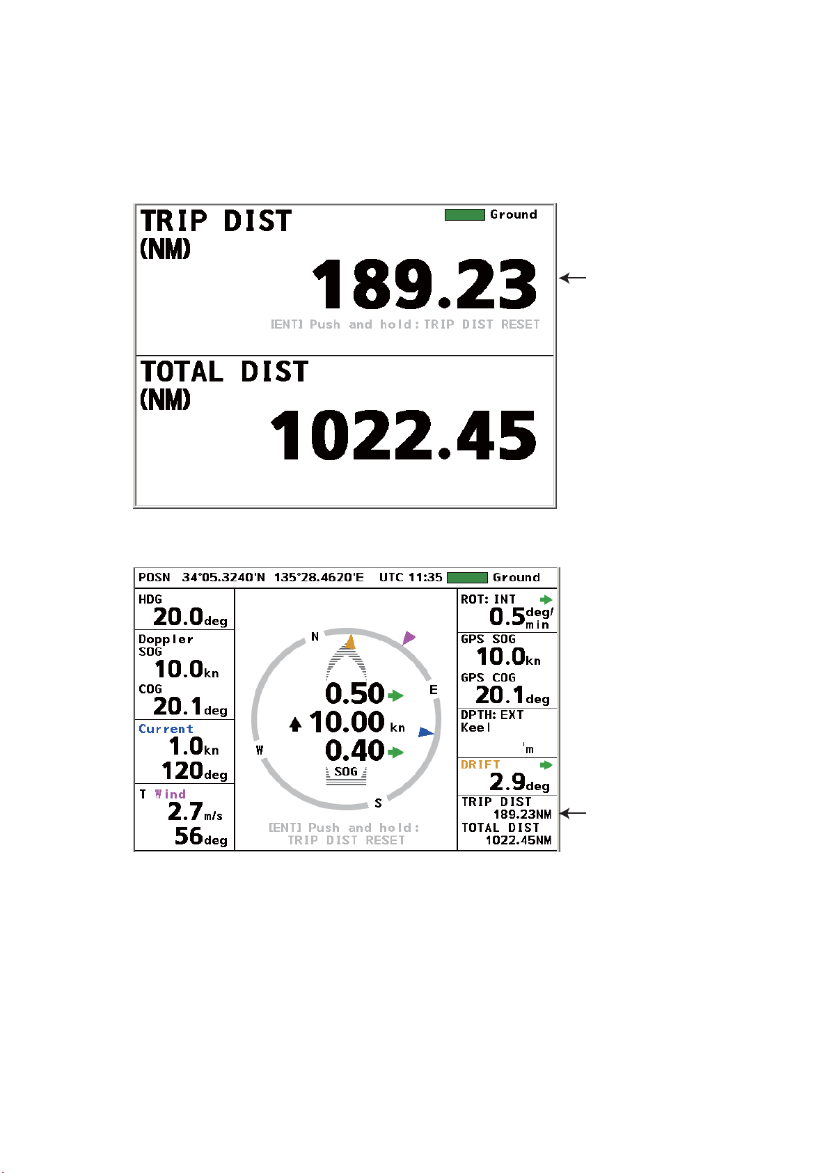
1.7 How to Reset the Trip Distance Indication
You can reset the trip distance indication on the displays that shows the trip distance.
Press the ENT key until the trip distance indication shows all zeroes. (Trip distance
can also be reset from the menu, with [Trip DIST]→ [RESET].)
Trip distance
Trip distance, total distance display
Navigation data display
56.0
Trip distance
1-8
Page 19
1. INTRODUCTION
1.8 How to Select Daytime and Nighttime Displays
The DAY/NT key selects the daytime (black characters on a white background) and
nighttime (white characters on a black background) displays alternately, for comfortable viewing according to the time of day.
DEPTH:
CURRENT
T WIND
Daytime
TRANSDUCER
56.0
CURRENT
T WIND
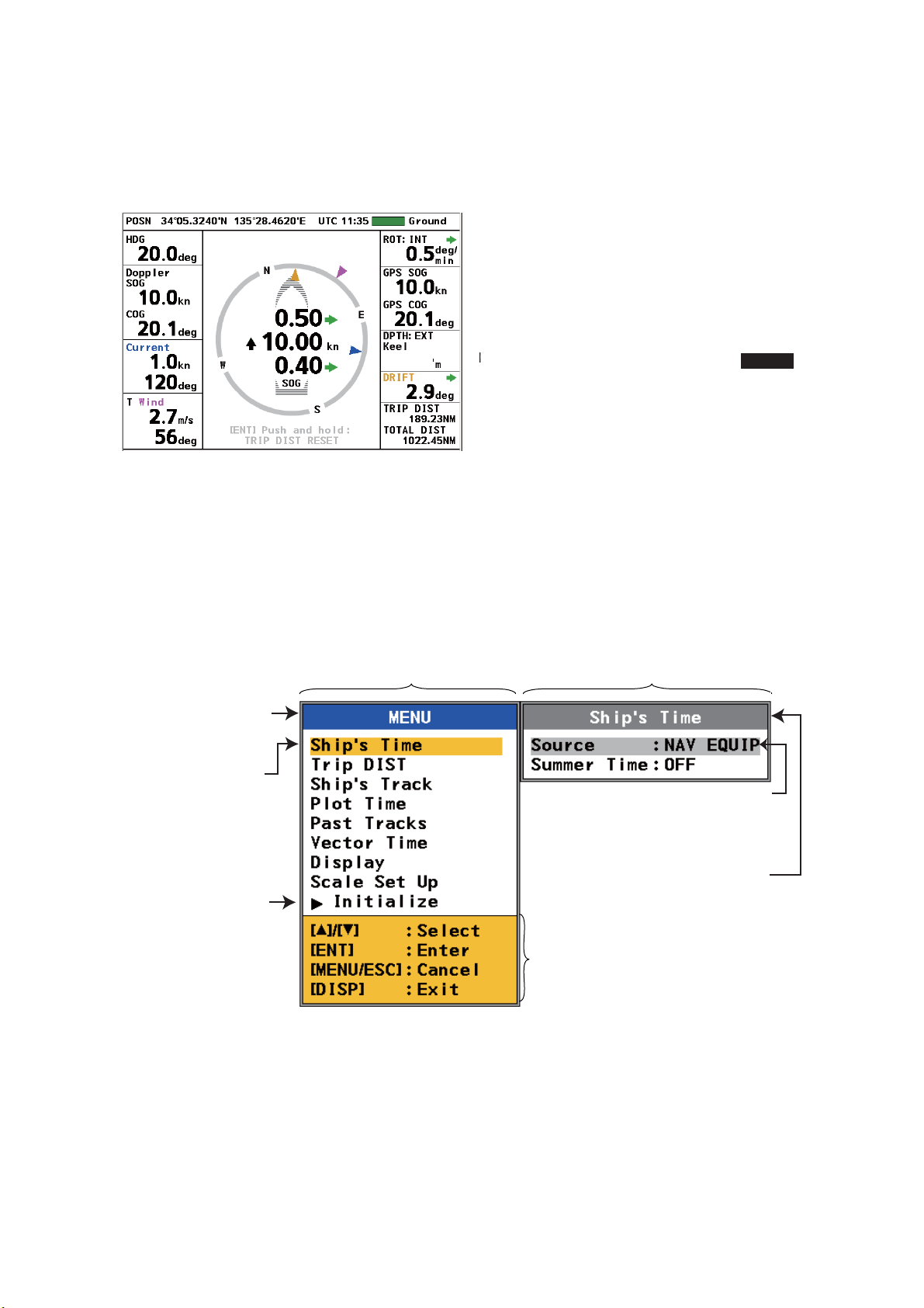
1.9 General Menu Operation
This section shows basic menu operation procedures.
1. Press the MENU/ESC key to open the menu. The menu window and the menu
options window for the currently selected menu item appear.
Menu window
Blue bar indicates
active window.
Current selection
highlighted in yellow.
Nighttime
Menu options window
Currently selected
item and option are
highlighted in gray.
DEPTH:
TRANSDUCER
56.0
Gray bar indicates
Arrow indicates
more items.
Press to show
the items.
Menu operation guidance
inactive window.
2. Press S, T to select a menu item then press the ENT key. Control is then given
to the menu options window.
Note: Hereafter we write “Select [name of menu item] then press the ENT key.”
where you use S,T to select an item or option and the ENT key to confirm selection.
1-9
Page 20
1. INTRODUCTION
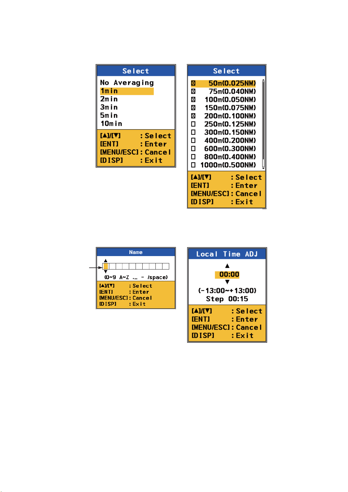
3. Select an item from the menu options window then press the ENT key. One of the
four types of boxes shown below appears. Follow the related procedure to make
your selection.
List box
1. Select option with ,
2. Press ENT key.
.
Input
cursor
(yellow)
Spinner box(alphanumeric data)
The input cursor is initially at
the far-left position.
1. Select character with , .
2. Press ENT key to confirm.
The input cursor moves to
next input point.
3. Repeat steps 1 and 2 to
complete the name.
Check box
1. Select option with ,
2. Press ENT key to check
or uncheck box.
Spinner box(numeric data)
1. Set value with ,
2. Press ENT key to confirm.
.
.
1-10
You can move the input cursor
with ENT, MENU/ESC.
ENT: Move right.
MENU/ESC: Move left.
4. Control is returned to the menu window. Press the DISP key to close the menu.
Page 21

2. NAVIGATION DATA DISPLAY
2.1 Navigation Data Display Overview
The navigation data display provides comprehensive navigation data (with connection
of related sensors) and a 3-axis speed display. When a data is lost, its numerical indication is shown with hyphens; for example, “---.-”. When a data is in error, its unit; for
example, “kn,” is shown in white characters on a red background. The “normal” unit
appears again when the data returns.
The 3-axis speed display mainly shows transverse speed at the reference point, longitudinal speed and transverse speed at the stern. The direction indicators can be
shown with arrows or text, selectable from the menu. Wind angle, drift angle and current (tide) direction are indicated with purple, brown and blue triangles, respectively.
Tracking mode monitor, tracking mode
Position
Time
(See section 1.5 for description.)
Heading
Doppler sonar
measured
SOG(STW), COG
Current (tide)
speed, direction
Wind reference,
speed,
angle
Message area
1) Transverse speed at
reference point
2) Longitudinal speed
3) Transverse speed at stern
(Requires rate-of-turn gyro
or gyrocompass. If no
connection, “--.--” appears.
Tracking mode
SOG: Speed over the ground
STW: Speed through the water
2)
*
1)
3)
*
*
3-axis speed display
ROT source,
ROT
GPS-measured
SOG, COG
56.0
56.0
Wind angle marker (purple)
Drift angle marker (brown)
Current (tide) direction marker (blue)
*
Direction shown with arrows or text,
selectable from the menu.
*
(green) (red) (black) (red)
Depth source,
depth (from transducer)
Drift angle
Trip distance,
Total distance run
2-1
Page 22

2. NAVIGATION DATA DISPLAY
2.1.1 Description of indications
Descriptions in clockwise order from top-left corner.
POSN Latitude and longitude position of your ship, input by a position-fixing equipment
(GPS, etc.).
Time Time, input by a position-fixing equipment, is available in UTC or local time, selectable
from the menu. The time format is shown before the time, "UTC" for Universal Coordinated Time, or "TIME" for local time. Daylight savings time can be activated and deactivated from the menu.
Tracking
monitor
Tracking
mode
ROT Source of ROT (Rate of Turn) and ROT value. The source of ROT can be selected
GPS SOG GPS-measured speed over the ground. When the GPS signal is lost, “--.-” appears.
GPS COG GPS-measured course over the ground.When the GPS signal is lost, “---.-” appears.
DPTH
DRIFT The drift angle. The drift angle is shown on the 3-axis speed display with a brown tri-
TRIP DIST Trip distance indication.
TOTAL DIST Total distance run indication. You can reset and adjust the indication from the menu.
Show the history of the tracking mode in the last three minutes. See section 1.5.
Show the current tracking mode: Ground, Water, or Auto. See section 1.5.
from the menu. See section 2.2.7.
Depth can be shown from the transducer or from the keel (
selectable from the menu.
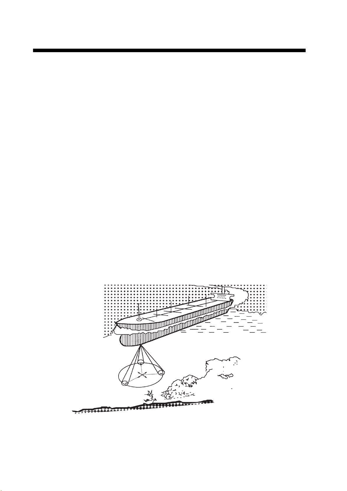
Note: The ultrasound beam is injected into water at an angle. The returning echo from
a bottom arrives at an angle to the transducer and is converted into a downward-measured depth. The depth measured to a flat bottom meets the accuracy denoted in the
specifications, however the depth to a sloping bottom is not the “true” depth.
angle.
fed from external source),
Wind Wind reference, speed and angle, input by a wind-measuring device. The wind angle
is shown on the 3-axis speed display with a purple triangle. Wind reference (True,
Theoretical or Relative) and wind averaging time can be set on the menu.
Current Current (tide) speed and direction. The direction of the current is shown in the 3-axis
speed display with a blue triangle. This graphic can show the direction the current is
flowing from, or the direction the current is flowing to. The blue triangle is inside the
3-axis speed display when the direction is “flowing to”, and outside that display when
the direction is “flowing from”. You can set the indication method on the menu. See
section 2.2.4.
Doppler
SOG (or
STW)
Doppler
COG
HDG Current heading, input by a gyrocompass. “0°” appears if there is no gyrocompass
Doppler sonar-measured speed over the ground or speed through the water.
Doppler sonar-measured course over the ground.
connected.
2-2
Page 23

2.2 How to Set Navigation Data
2.2.1 Time
This section shows you how to select the source for time, set local time, and turn summer time indication (daylight savings time) on or off.
1. Press the MENU/ESC key to open the menu.
2. Select [Ship’s Time] then press the ENT key.
3. Select [Source] then press the ENT key.
2. NAVIGATION DATA DISPLAY
4. Select [Internal] or [NAV EQUIP] then press the ENT key. Select [Internal] to use
local time, or [NAV EQUIP] to use UTC time. For [Internal], the [Local Time ADJ]
screen appears; go to step 5. For [NAV EQUIP], go to step 6.
5. Use S, T to set the time difference between local time and UTC time then press
the ENT key.
2-3
Page 24
2. NAVIGATION DATA DISPLAY
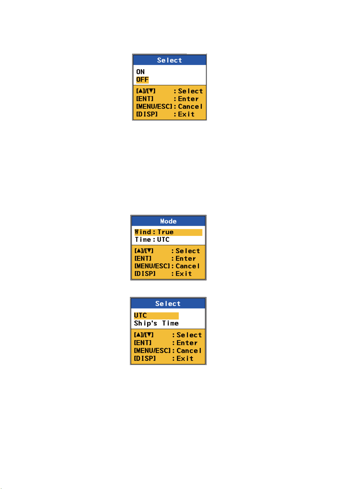
6. Select [Summer Time] (to turn the daylight savings time indication on or off) then
press the ENT key.
7. Select [ON] or [OFF] then press the ENT key.
8. Press the DISP key to close the menu.
2.2.2 Time format
You can display time in UTC or ship’s time (local time).
1. Press the MENU/ESC key to open the menu.
2. Select [Scale Set Up] then press the ENT key.
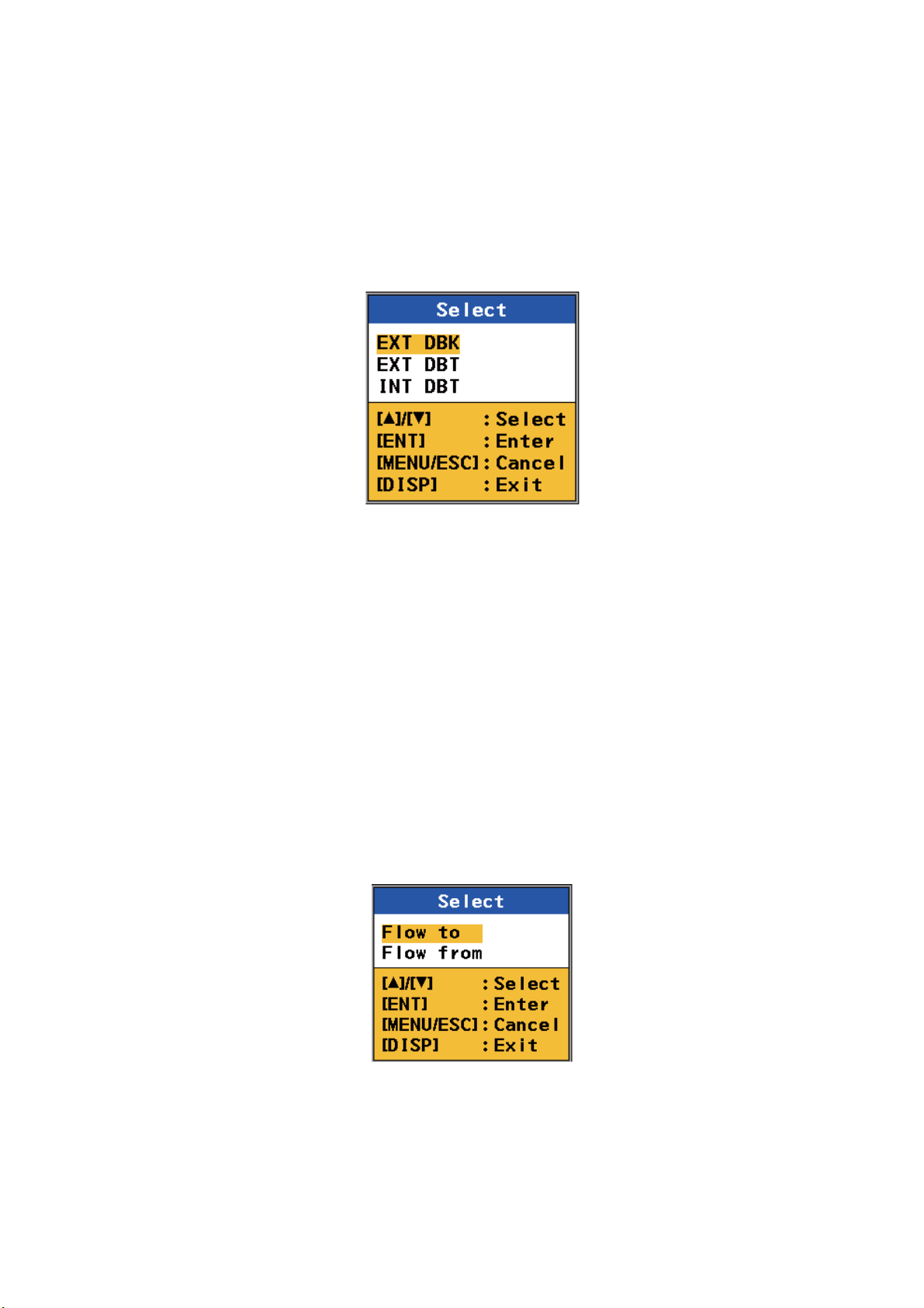
3. Select [Mode] then press the ENT key.
4. Select [Time] then press the ENT key.
2-4
5. Select [UTC] or [Ship’s Time] then press the ENT key.
6. Press the DISP key to close the menu.
Page 25
2.2.3 Depth measurement reference
The depth can be measured from below the keel (fed from external source), or below
the transducer. The depth data can be supplied by the transducer of the DS-60 or an
external transducer.
1. Press the MENU/ESC key to open the menu.
2. Select [Scale Set Up] then press the ENT key.
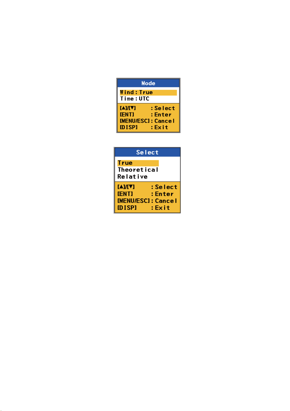
3. Select [Depth REF] then press the ENT key.
2. NAVIGATION DATA DISPLAY
4. Select desired depth measurement reference then press the ENT key.
[EXT DBK]: Depth Below the Keel, measured by external equipment
[EXT DBT]: Depth Below the Transducer, measured by other transducer
[INT DBT]: Depth Below the Transducer, measured by the transducer of the
DS-60
5. Press the DISP key to close the menu.
2.2.4 Current direction
The direction of tide currents can be shown as flowing from or flowing to. The current
direction indicator (blue triangle marker) is inside the 3-axis speed display for flowing
to and outside the display for flowing from. (See the figure on the next page.)
1. Press the MENU/ESC key to open the menu.
2. Select [Scale Set Up] then press the ENT key.
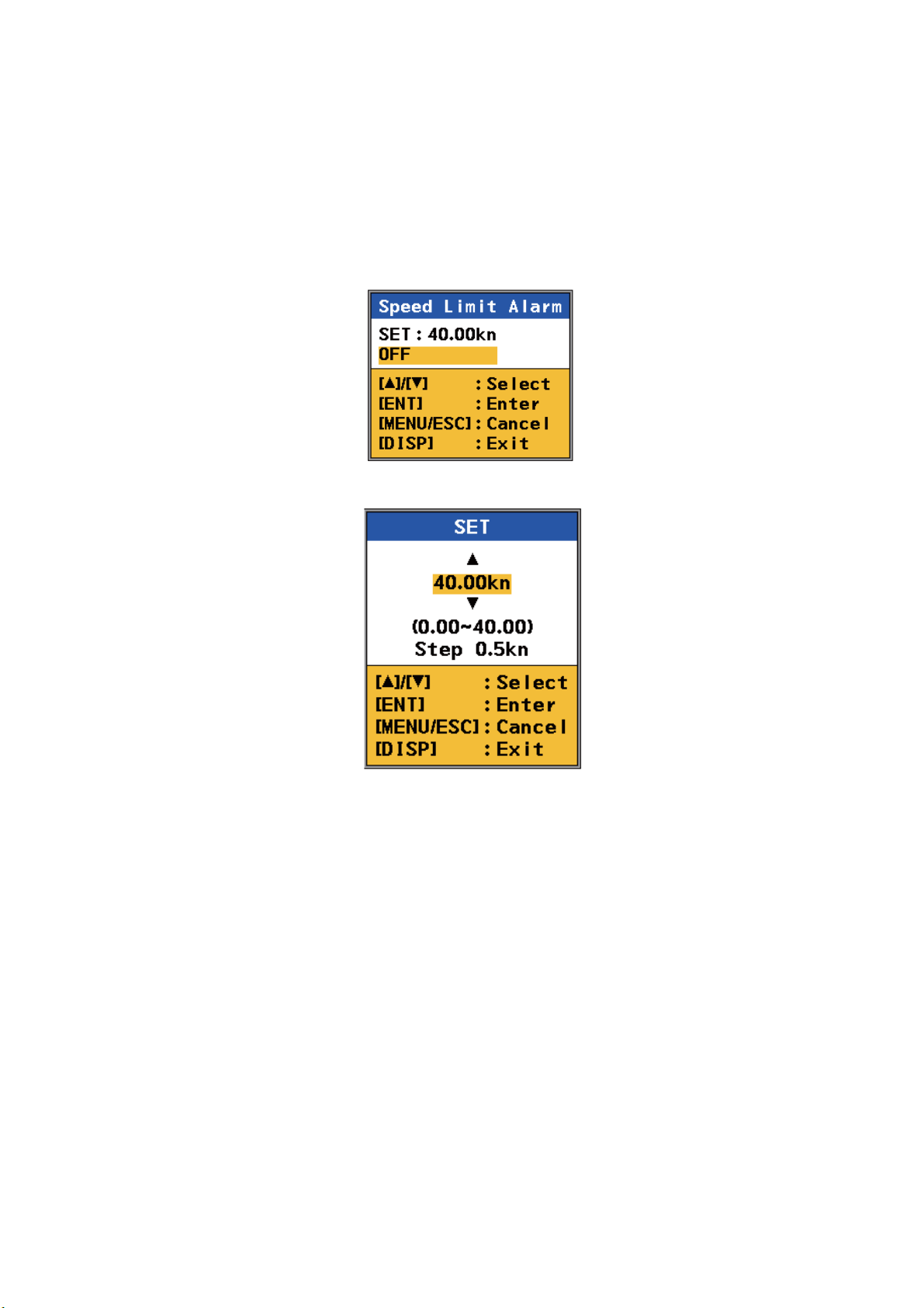
3. Select [CUR Direction] then press the ENT key.
4. Select [Flow to] or [Flow from] then press the ENT key.
2-5
Page 26

2. NAVIGATION DATA DISPLAY
5. Press the DISP key to close the menu.
56.0
Flow to (example: 120°)
Flow from (example: 300°)
56.0
2-6
Page 27
2.2.5 Wind angle
The wind angle can be shown as Relative, True or Theoretical.
1. Press the MENU/ESC key to open the menu.
2. Select [Scale Set Up] then press the ENT key.
3. Select [Mode] then press the ENT key.
4. Select [Wind] then press the ENT key.
2. NAVIGATION DATA DISPLAY
5. Select [True], [Theoretical] or [Relative] then press the ENT key.
[True]: The wind speed and angle minus movement of ship, reference to North.
[Theoretical]: The wind speed and angle minus movement of ship, reference to
ship’s bow.
[Relative]: The speed and relative direction that the wind appears to blow with ship
in motion, reference to ship’s bow.
6. Press the DISP key to close the menu.
2-7
Page 28

2. NAVIGATION DATA DISPLAY
2.2.6 Wind averaging time
Set the wind averaging time in minutes. Select [No Averaging] for no averaging. The
higher the time, the smoother the wind data, but response to the changes in wind
speed and angle slows.
1. Press the MENU/ESC key to open the menu.
2. Select [Wind Average] then press the ENT key.
3. Select a value then press the ENT key.
4. Press the DISP key to close the menu.
2.2.7 ROT sensor
Select the ROT sensor as follows:
1. Press the MENU/ESC key to open the menu.
2. Select [ROT Sensor] then press the ENT key.
3. Select a source then press the ENT key.
[Internal]: Select this item if the optional Rate-Of-Turn-Gyro is connected.
[External ROT]: Receive ROT data from external ROT sensor.
[External HDG]: Receive ROT data from gyrocompass or heading sensor.
2-8
4. Press the DISP key to close the menu.
Page 29
2.3 How to Set the Speed Alarm
The speed alarm sets the maximum allowable speed. If the speed of the ship goes
higher than the speed set here, the audible alarm sounds and the message "Speed
Alarm 300" appears. You can stop the audible alarm with the ALARM ACK key. The
message remains on the screen until you deactivate the alarm.
1. Press the MENU/ESC key to open the menu.
2. Select [Speed Limit Alarm] then press the ENT key.
3. Select [SET] then press the ENT key.
2. NAVIGATION DATA DISPLAY
4. Press S or T to set the maximum allowable speed then press the ENT key. The
setting range is 0.05 to 40 kn, in 0.5 kn increments.
5. Press the DISP key to close the menu.
To deactivate the alarm, select [OFF] at step 3 then press the DISP key.
2-9
Page 30

2. NAVIGATION DATA DISPLAY
This page is intentionally left blank.
2-10
Page 31

3. BERTHING DISPLAY
3.1 Berthing Display Overview
The berthing display shows ship’s track (past and/or predicted) and provides help with
berthing operations. With position and heading inputs, customizable berthing lines can
be shown to help in berthing.
The display orientation is available in Head-up and North-up. Head-up has your heading at the screen top and North-up has North at the top.
The navigation data, which appears at the left side of the display, can be shown or hidden as necessary.
Current (tide) direction and wind angle markers, shown with blue and purple triangle
markers respectively, provide quick identification of respective direction or angle.
The 3-axis speed display shows ship’s speed in three axes: transverse speed at the
reference point, longitudinal speed, and transverse speed at the stern. The display is
positioned at the bottom-right corner or top-left corner depending on the location of the
own ship marker. You can show or hide the display as required.
Heading
ROT source,
ROT
Doppler sonar
SOG(STW), COG
Current (tide) speed,
direction
Wind reference
wind speed
wind angle
Depth
(below keel)
Message area
* Green: ground tracking
Blue: water tracking
Own ship marker
CCRP
(Consistent Common Reference Point)
Position
Wind angle
marker (purple)
Current
(tide)
direction
1.5
231
marker
(blue)
3.2
321
123
SPEED ALARM 300
Berthing
line
Speed Vector (Shows predicted
ship position at end of selected
time interval.)
Heading Line
(Indicates your heading.)
Beam Line
KOBE-1
Predicted position marker (purple)
Name of berthing line
Tracking mode monitor*
Time
Speed vector
The own ship marker indicates current position.
The marker is green for ground tracking and blue
for water tracking. The marker is scaled
according to ship length and width, set on the
[Setting Ship Data] menu. If the range and
dimensions of the ship are as shown below, the
marker is shown with concentric circles.
Range x 8> Ships length x 30, or Width x 52
Tracking mode
Past position marker
Ground tracking: light green
Water tracking: light blue
Track (solid line)
Stern track: black
Ref. pos. track: green*
Own ship marker*
(current position)
3-axis speed display
Transverse speed at
reference point
Longitudinal speed
Transverse speed at stern
Range/Display
orientation (N UP, H UP)
Own ship
marker
3-1
Page 32

3. BERTHING DISPLAY
3.2 Display Range
3.2.1 How to select a range
The display range is the distance between grid sides on the berthing display. Use the
RNG key to select a range. The range appears below the 3-axis speed display as
shown below. The system is pre-set with five ranges (nm): 0.025, 0.04, 0.05, 0.075
and 0.1. A total of 11 ranges are available and you can select the ranges to use from
the menu, as shown in the next section.
Range
Display
range
Grid
SOG m/s
0.01
12.45
0.31
0.050 NM/DIV H UP
3.2.2 How to pre-set ranges
The berthing display has a total of 11 ranges. Select the ranges to use, following the
procedure shown below. A minimum of one range must be turned on.
1. Press the MENU/ESC key to open the menu.
2. Select [Set Up Scale] then press the ENT key.
3. Select [Range] then press the ENT key.
4. Select a range then press the ENT key. Show
“X” in a check box to select the range, or remove
the “X” to deselect the range.
5. Press T to show and select [Save] then press
the ENT key.
Note: If all ranges are turned off, the message
"No item be selected" appears. Select at least
one range.
6. Press the DISP key to close the menu.
Set with RNG key
3-2
Page 33

3.3 Track
The DS-60 uses speed data to plot your ship’s track on the display. You can show past
track or predicted track, or both past and predicted tracks.
3.3.1 Types of tracks
Two types of track are available: past and predicted.
Past track
Past track can be shown with past ship markers or both solid lines and past ship markers.
There are two types of past track: reference position track and stern track. The reference position track is green (ground tracking) or blue (water tracking), and the stern
track is black. The tracks of the past five minutes are shown. .
A past track marker is added every 30 seconds. The markers are colored light blue for
water tracking, and light green for ground tracking. The last five minutes of past track
markers are shown
3. BERTHING DISPLAY
You can select the type of past track to show from the menu. See section 3.3.3 for the
procedure.
Own ship marker
Marker characteristics
- One marker is added
every 30 seconds.
- Water tracking: Light blue
- Ground tracking: Light green
Past track
(solid line)
Past track
(marker)
Past track (marker and solid line) Past track (solid line)
Own ship marker
Reference position track
Ground tracking: Green
Water tracking: Blue
Stern track (black)
3-3
Page 34

3. BERTHING DISPLAY
Predicted track
The predicted track feature shows estimated position of your ship at the end of the selected time interval. (See section 3.3.4 for the procedure.) The estimated position is
calculated from the reference point and stern speeds taken from the ground and water
tracking speed data. The marker is purple, hollow and dashed to distinguish it from the
own ship marker and the past track markers.
Predicted track
marker (purple)
Own ship marker
Predicted track
3.3.2 How to select the type of track to display
1. Press the MENU/ESC key to open the menu.
2. Select [Ship’s Track] then press the ENT key.
3. Select the type of track to display then press the ENT key. Select [OFF] to hide all
tracks.
4. Press the DISP key to close the menu.
3-4
Page 35

3.3.3 How to select the past track format
The past track can be shown with a solid line or solid line and past track markers. See
the illustration on page 3-3.
1. Press the MENU/ESC key to open the menu.
2. Select [Past Tracks] then press the ENT key.
3. Select [ON] or [OFF] then press the ENT key.
[ON]: Past track marker + solid line
[OFF]: Past track marker only
3. BERTHING DISPLAY
4. Press the DISP key to close the menu.
3.3.4 How to select the predicted track plot interval
Select the interval at which to plot the predicted track as follows:
1. Press the MENU/ESC key to open the menu.
2. Select [Plot Time] then press the ENT key.
3. Select a time then press the ENT key. A new marker is plotted at equally timespaced intervals of 1/5 of the plot time selected. For example, if you select the 10minute interval, the predicted position is plotted at two-minute intervals.
4. Press the DISP key to close the menu.
3-5
Page 36

3. BERTHING DISPLAY
3.4 How to Select Vector Time
The tip of the vector line on the own ship marker shows the estimated position of your
ship after the selected vector time elapses, using the current course and speed. You
can adjust the length of the vector line to see estimated position at the end of the prescribed time interval.
1. Press the MENU/ESC key to open the menu.
2. Select [Vector Time] then press the ENT key.
3. Select a vector time then press the ENT key. The longer the time, the longer the
vector line.
4. Press the DISP key to close the menu.
3-6
Page 37

3. BERTHING DISPLAY
3.5 How to Show, Hide Navigation Data and 3-axis Speed Data
The berthing display can show NAV data and 3-axis speed data. You can show them
in separate windows, show the 3-axis speed data in the NAV data window, or show
only the 3-axis speed data (no NAV data). Long-push the ENT key to show or hide the
data, in the sequence shown below. The data can also be shown or hidden with [Data
Display] in the [Scale Set Up] menu.
3-axis speed
data in NAV
data window
NAV
data
Long-push ENT.
56.0
3-axis speed data in NAV data
56.0
3-axis speed data and NAV data
Long-push ENT.
3-axis speed
data
Long-push ENT.
3-axis speed data (NAV data OFF)
3-axis speed
data
3-7
Page 38

3. BERTHING DISPLAY
3.6 Berthing Line
A berthing line that represents an intended berth can be shown to help in berthing
operations. The DS-60 stores a maximum of 100 berthing lines, and a berthing line
can have a maximum of three points. All berthing lines within the current display range
are automatically shown. A berthing line is automatically sent to all powered sub display units the moment the line is saved.
3.6.1 How to create a berthing line
Berthing lines can only be created from the main display unit.
1. Press the MENU/ESC key to open the menu.
2. Select [Berthing Line] then press the ENT key.
3. Select [Edit] then press the ENT key.
3-8
Page 39

4. Select an empty number then press the ENT key.
5. [Name] is selected; press the ENT key.
3. BERTHING DISPLAY
Input
cursor
6. Enter a name for the berthing line. For example, the name of the harbor related to
the berthing line.
1) The input cursor is at the far-left position. Press S or T to select a character
then press the ENT key. The input cursor moves to the next input point.
2) Repeat step 1) to complete the name. To move the input cursor, use the ENT
key to move it right, the MENU/ESC key to move it left.
Note: If you do not enter a name, the message "Please enter name." appears. Enter a name.
7. Press the ENT key to go to the [SET] menu.
8. Press T to select the [LAT] line of [Point1] then press the ENT key.
9. Use S or T to select the first digit of the latitude position then press the ENT key.
Enter the remaining digits in the same method. (Use the ENT key to move the cursor right, and the MENU/ESC key to move the cursor left.)
3-9
Page 40

3. BERTHING DISPLAY
10. Select the [LON] line of [Point1] then press the ENT key.
11. Enter the longitude, same as how you entered the latitude.
12. Enter the points 2 and 3.
13. Select [Harbour View] then press the ENT key. The display shows
• Berthing line
• Name of berthing line, and
• Latitude and longitude position of each point.
Berthing line
Name of
berthing line
Position of
points
Note: If the distance between two consecutive points is more than one degree,
the message “Points too far, maximum distance between points is 1 degree” appears. Reenter point(s).
3-10
North Up
Page 41

3. BERTHING DISPLAY
14. To save the line, press the MENU/ESC key to return to the [SET] dialog box (see
the figure at the top of page 3-9). Press T to show and select [Exit] then press the
ENT key. (The berthing line is sent to all active sub display units when the ENT
key is pressed.)
Note: If you select [Harbour View] without entering a name, the message "Harbour Name/Berthing Line plans must be named individually, please enter name."
appears. Enter a name.
15. To make another berthing line, repeat steps 4-14. To finish, press the DISP key.
Note: You can edit berthing lines. Open the [Berthing Line] menu, select [Edit] then
select a berthing line. The remaining procedure is similar to how you enter a berthing
line.
3-11
Page 42

3. BERTHING DISPLAY
3.6.2 How to share berthing lines with sub display units
Berthing lines created at the main display unit are automatically sent to all sub display
units that are active when the line is created. To send the berthing lines after a sub
display unit becomes active, do as follows:
1. Press the MENU/ESC key to open the menu.
2. Select [Berthing Line] then press the ENT key.
3. Select [Share] then press the ENT key.
4. Select [Yes] then press the ENT key. All berthing lines in the sub display units are
replaced with the berthing lines from the main display unit.
5. Press the DISP key to close the menu.
3-12
Page 43

3.6.3 How to delete a berthing line
If you do not need a berthing line that you have made, you can delete the line as
shown below. The line is deleted from both the main and sub display units.
1. Press the MENU/ESC key to open the menu.
2. Select [Berthing Line] then press the ENT key.
3. Select [Delete] then press the ENT key to show the list of berthing lines.
3. BERTHING DISPLAY
4. Select the line to delete then press the ENT key. You are asked if you are sure to
delete the line.
5. Select [Yes] then press the ENT key.
6. Press the DISP key to close the menu.
3-13
Page 44

3. BERTHING DISPLAY
This page is intentionally left blank.
3-14
Page 45

4. SPEED GRAPHIC DISPLAY
r
The speed graphic display, available with the sub display unit, provides absolute
speed or ahead and astern speeds, in a speedometer arrangement.
4.1 Speed Graphic Indications
Tracking mode monito
Tracking mode
Tracking mode
(SOG or STW)
Ahead speed
Astern speed
4-1
Page 46

4. SPEED GRAPHIC DISPLAY
4.2 How to Activate the Speed Graphic
Select the display number where to show the speed graphic and the scale for the
astern speed and ahead speed indications. The total display range for the two indications is 70 knots, and you can divide that total as required.
1. Press the MENU/ESC key to open the menu.
2. Select [Scale Set Up] then press the ENT key.
3. Select [Speed Graphic] then press the ENT key.
4. Select the display number (default display number for the graphic display is
DISP5) where to show the speed graphic display then press the ENT key.
4-2
Page 47

4. SPEED GRAPHIC DISPLAY
5. The cursor is selecting [Astern SPD Scale]; press the ENT key.
6. Select the scale range for the astern speed then press the ENT key.
7. Select [Ahead SPD Scale] then press the ENT key.
8. Select the scale range for the ahead speed then press the ENT key.
9. Press the DISP key to close the menu.
4.3 How to Select the Display Format for the Speed Graphic
The speed graphic can show absolute speed or ahead and astern speeds. Absolute
speed is shown in three digits and ahead and astern speeds in four digits.
1. Press the MENU/ESC key to open the menu.
2. Select [Speed Select] then press the ENT key.
4-3
Page 48

4. SPEED GRAPHIC DISPLAY
3. Select [Forward-After] or [Vector] then press the ENT key. See the illustration below.
FWD
“Forward-After” setting
(Four-digit speed indication)
When Direction SYM is set to
“Text”, “FWD” or “AFT” is shown.
FWD or AFT not shown when
“Arrows” is selected.
Speedometer display
“Forward-After” setting
(Four-digit speed indication)
When Direction SYM is set to
“Text”, “FWD” or “AFT” is shown.
Arrows shown when “Arrows” is
selected.
(Three-digit speed indication)
1-axis speed display
4. Press the DISP key to close menu.
“Vector” setting
(Three-digit speed indication)
No text or arrows shown.
“Vector” setting
No text or arrows shown.
4-4
Page 49

4. SPEED GRAPHIC DISPLAY
4.4 How to Change the Speed Graphic Format
The default speed graphic has the zero point for the ahead and astern speedometers
on the left side of the display, and the pointer moves rightward with increase in ahead
speed. If desired, you can reverse that arrangement.
This setting also changes the position of the direction indicators on the digital speed
displays. See section 5.5.
1. Press the MENU/ESC key to open the menu.
2. Select [Scale Set Up] then press the ENT key.
3. Select [SYM Location] then press the ENT key.
4. Select [Left] or [Right] then press the ENT key.
[Left]: The pointer moves rightward with increase in ahead speed, and the zero
point for the speedometers is on the left.
[Right]: The pointer moves leftward with increase in ahead speed, and the zero
point for the speedometers is on the right.
n
o
i
t
c
e
r
i
d
w
o
l
f
d
e
e
p
s
d
a
e
h
A
d
e
e
p
s
n
r
e
t
s
A
SYM Location “Left”
A
h
e
a
d
s
p
e
e
d
f
l
o
w
d
i
r
e
c
t
i
o
n
5. Press the DISP key to close the menu.
A
s
t
e
r
n
s
p
e
e
d
SYM Location “Right”
4-5
Page 50

4. SPEED GRAPHIC DISPLAY
This page is intentionally left blank.
4-6
Page 51

5. OTHER OPERATIONS
This chapter provides the descriptions for the menu items not described in other chapters.
5.1 How to Set the Displays
The DS-60 is pre-set with four displays and you can set a maximum of seven displays.
There are two types of screen arrangements: full screen and two-way horizontal split
screen. A full-screen display can show a graphic display (navigation data, berthing,
speed graphic (sub display unit only)), or digital data (trip distance, heading, etc.). A
two-way horizontal split screen can show two digital data.
1. Press the MENU/ESC key to open the menu.
2. Select [Display] then press the ENT key.
3. Select a display number ([DISP1] - [DISP7]) then press the ENT key.
Full screen
Two-way horizontal split screen
Blank (no display)*
* Not available with DISP1.
5-1
Page 52

5. OTHER OPERATIONS
4. Select the full screen, two-way horizontal split or blank icon (no display) then
press the ENT key. The display now shows the selections available for the type of
screen you selected.
Options available with full screen
Options available with two-way
horizontal split screen
Grayed item not available for selection.
5. Select a data item then press the ENT key. See the illustration on the next page
for the appearance of the displays.
For the two-way horizontal split screen, the screen shown below appears after
you select the data to show in the top half of the screen. Select a data item for the
bottom half of the screen then press the ENT key.
Grayed item not available for selection.
6. Press the DISP key to close the menu.
5-2
Page 53

5. OTHER OPERATIONS
Navigation data
56.0
Berthing (North-up)
TOTAL DIST
Full-screen displays
DPTH: EXT
Keel
56.0
56.0
Berthing (Head-up)
Trip distance
Horizontal split displays
Trip distance, ROT
TOTAL DIST
Total distance, heading
Total distance
3-axis speed
Speed graphic
(sub display unit only)
Heading and 3-axis speed
2-axis speed
1-axis speed
(sub display unit only)
Heading, ROT
Trip distance, total distance
5-3
Page 54

5. OTHER OPERATIONS
5.2 Key Beep On/Off
A key beeps when it is pressed. You can turn this beep on or off.
1. Press the MENU/ESC key to open the menu.
2. Select [Key Beep] then press the ENT key.
3. Select [ON] or [OFF] then press the ENT key.
4. Press the DISP key to close the menu.
5.3 How to Adjust Key Dimmer
You can adjust the dimmer for the keys as follows:
1. Press the MENU/ESC key to open the menu.
2. Select [Key BRILL] then press the ENT key.
5-4
3. Select a dimmer level then press the ENT key. The higher the figure, the higher
the dimmer level.
4. Press the DISP key to close the menu.
Page 55

5. OTHER OPERATIONS
5.4 How to Select Direction Symbol Format
The direction symbols for speed and ROT can be shown with arrows or text.
1. Press the MENU/ESC key to open the menu.
2. Select [Scale Set Up] then press the ENT key.
3. Select [Direction SYM] then press the ENT key.
4. Select [Arrows] or [Text] then press the ENT key.
Arrows Text
STBD, S*
PORT, P*
FWD
AFT
* Navigation data display, berthing display
5. Press the DISP key to close the menu.
5-5
Page 56

5. OTHER OPERATIONS
5.5 How to Select the Location for the Direction Symbols
The direction symbols (arrows) for the transverse speeds (reference point, stern) can
be displayed on the left or right side of those indications on the digital speed displays.
(The ship’s speed direction indicator (↑) is on the left always.) This setting does not
affect the 3-axis speed display in the navigation data display.
This setting also changes the format for the speed graphic. See section 4.4.
1. Press the MENU/ESC key to open the menu.
2. Select [Scale Set Up] then press the ENT key.
3. Select [SYM Location] then press the ENT key.
4. Select [Left] or [Right] then press the ENT key.
[Left]: The direction indicators are on the right side of the speed indications.
[Right]: The direction indicators are on the left side of the speed indications.
Direction indicators
SYM Location “Left”
(Right-pointing arrow indicates
movement in starboard direction
when viewed from bow-mounted
display unit.)
Direction symbols in heading and speed display
5. Press the DISP key to close the menu.
SYM Location “Right”
(Left-pointing arrow indicates
movement in starboard direction
when viewed from stern-mounted
display unit.)
5-6
Page 57

5.6 Total Distance Run
5.6.1 How to reset total distance run
1. Press the MENU/ESC key to open the menu.
2. Select [Total DIST] then press the ENT key.
3. [RESET] is selected; press the ENT key. You are asked if you are sure to reset
the total distance run.
5. OTHER OPERATIONS
4. Select [Yes] then press the ENT key.
5. Press the DISP key to close the menu.
5-7
Page 58

5. OTHER OPERATIONS
5.6.2 How to set total distance run
The total distance run figure can be adjusted as required.
1. Press the MENU/ESC key to open the menu.
2. Select [Total DIST] then press the ENT key.
3. Select [SET] then press the ENT key.
4. Use S or T to set a value then press the ENT key. (You can move the cursor to
the right with the ENT key. Use the MENU/ESC key to move the cursor to the left.)
5. Repeat step 4 as required.
6. Press the DISP key to close the menu.
5-8
Page 59

5.7 System Parameters
The [System Parameters] menu provides the functions that once set do not require
regular adjustment.
1. Press the MENU/ESC key to open the menu.
2. Select [System] then press the ENT key.
3. Select [System Parameters] then press the ENT key.
5. OTHER OPERATIONS
5-9
Page 60

5. OTHER OPERATIONS
System parameters menu description
Item Description Available settings
Ship’s Speed
Average
Current
Average
Track
Depth
Current
Measurement
CALC
Average
IR Turn the interference rejector on or off. Turn the rejector on
Log Pulse
Speed
Set averaging time for ship’s speed. The default
setting is acceptable for most conditions. If the speed
indication is unstable, select the setting that gives
stable speed data.
Set averaging time for current (tide) speed and direction.
The default setting is acceptable for most conditions. If the
current data changes randomly, select the setting that
gives stable current data, but does not slow response to
changes in current data.
Set the water tracking depth for measurement of throughthe-water-speed. If the through-the-water speed readout is
unstable, raise the setting.
Set the depth at which to measure current (tide) speed and
direction.
Smooth the heading data, which is received every second. No Averaging, 10s,
when an echosounder is connected to the DS-60, to
prevent mutual interference.
Select the data to use to calculate distance run. STW&GPS;
5s, 10s, 15s, 30s,
60s
1min, 2min, 3min,
5min, 10min
0.5 - 25.0(m), 0.1m
steps
0.5 - 25.0(m), 0.1m
steps
30s, 60s, 90s, 120s
ON, OFF
SOG&STW&GPS;
SOG&GPS; STW
Log Pulse
Output
Analog
Speed
Analog
Output
Beam
Direction
TVG
Curve
Select the log pulse speed to output to external equipment.
• Forward: Forward speed only
• Forward-After: Forward and after speeds
• Vector: Synthesized speed consisting of forward, after,
port and starboard speeds
Select the source for the analog speed indication. STW&GPS;
Select the analog speed to output to external equipment.
• Forward: Forward speed only
• Forward-After: Forward and after speeds
• Vector: Synthesized speed consisting of forward, after,
port and starboard speeds
Select the beam directions to use to measure speed.
Forward: 0°, 120°, 240°
After: 60°, 180°, 300°
Used for internal calculations, and the default setting is
zero. Do not change the setting. Contact a FURUNO agent
or dealer for information.
Forward; ForwardAfter; Vector
SOG&STW&GPS;
SOG&GPS; STW
Forward; ForwardAfter; Vector
Forward, After
0 -19
5-10
Page 61

6. MAINTENANCE, TROUBLESHOOTING
This chapter provides the maintenance and troubleshooting information for the operator. If you cannot restore normal operation, do not try to check inside the equipment.
Refer any repair work to a qualified technician.
WARNING
ELECTRICAL SHOCK HAZARD
Do not open the equipment.
This equipment uses high
voltage that can cause
electrical shock.
0nly qualified persons can
work inside the equipment.
6.1 Maintenance
Periodic maintenance is important to keep good performance. Check the system at
regular intervals with the procedures shown in the table below.
Item Check point Action
Cables Check that all cables are
tightly fastened. Check
the cables for corrosion
and rust.
NOTICE
D
o not apply paint, anti-corrosive
sealant or contact spray to plastic
parts or equipment coating.
Those items contain products that can
damage plastic parts and equipment
coating.
Connect loosened cables.
Replace any damaged cables.
Cabinet Dust on the cabinets Remove dust with a dry, clean cloth. Do not
use commercial cleaners to clean any part
of the equipment. Commercial cleaners can
remove paint and markings.
LCD
(display unit)
Transducer Marine life and growth on
Dust on the LCD Wipe the LCD carefully to prevent scratch-
ing, using tissue paper and an LCD cleaner.
To remove dirt or salt deposits, use an LCD
cleaner, wiping slowly with tissue paper so
as to dissolve the dirt or salt. Change paper
frequently so the salt or dirt will not scratch
the LCD. Do not use commercial cleaners
to clean any part of the equipment. Commercial cleaners can remove paint and
markings.
Marine life and growth on the transducer
the transducer
can reduce sensitivity. When the ship is
dry-docked, carefully remove any marine
life and growth from the transducer. Paint
the transducer yearly with anti-fouling paint
(no other type of paint is permitted).
6-1
Page 62

6. MAINTENANCE, TROUBLESHOOTING
6.2 Consumable Parts
6.2.1 Fuse replacement
The fuse in the Display Unit, Transceiver Unit, Distributor Unit and Rate-of-Turn Gyro
protects those units from overvoltage. If you cannot turn on the power, have a technician check if the fuse inside the Display Unit has blown. If the fuse has blown, find the
cause before replacing the fuse. If the fuse blows again, contact your dealer.
WARNING
Use the correct fuse.
A wrong fuse can damage the equipment
or cause fire.
Unit
Display
Unit
Transceiver
Unit
Distributor
Unit
Rate-ofTurn Gyro
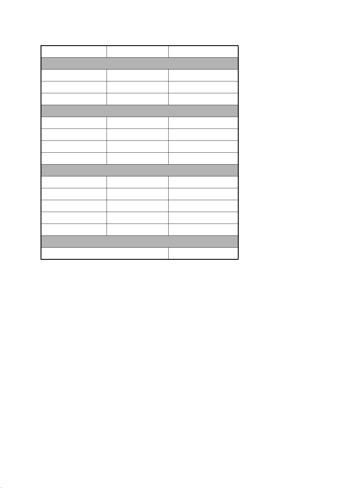
6.2.2 Product life
Unit Approx. Life (@55°C) Replacement Part
DS-600
Backlight
DS-670
Rate-of-Turn Gyro
(Fiber Optic Gyro)
Fuse
Rating
2A FGMB 2A
AC125V PBF
3A FGB01 3A
AC250V PBF
5A FGB01 5A
AC250V PBF
2A FGB01 2A
AC250V PBF
30,000 h Panel assy.: DS-600
17,520 h Model: HOFG-1F (VER1.0)
Type Code No. Qty Remarks
000-157-479-10 1 Inside unit
000-155-841-10 2 Inside unit
000-155-840-10 2 Inside unit
000-155-829-10 1 Inside unit
(001-098-070-00)
6-2
Page 63

6.3 Troubleshooting
This section provides the troubleshooting procedures that the user can follow to
restore normal operation. If you cannot restore normal operation, contact a qualified
FURUNO technician for instruction.
Problem Possible cause Action
General
6. MAINTENANCE, TROUBLESHOOTING
The power cannot be
turned on.
The power is on, but
the screen is black.
Doppler speed indication
The indication does
not change (display
has frozen) and the
speed unit is red.
The indication shows
“-.--”
Loosened power cable. Fasten the power cable.
Blown fuse. Get a qualified technician to
The brilliance is too low. Increase the brilliance.
• Air bubbles on the transducer
• The ground tracking mode is
• Air bubbles on the transducer
• The ground tracking mode is
face.
used when the depth is 200 m
or more.
face.
in use when the depth is 200
m or more.
check the fuse in the
display unit. Replace the
fuse if it has blown.
• Wait for the air bubbles
to disappear.
• Select the water tracking
mode or auto mode.
• Wait for the air bubbles
to disappear. If the problem continues, check the
transducer.
• Select the water tracking
mode or auto mode.
GPS speed, position indication
The indication shows
“-.--”
The indication shows
hyphens (-) at digit
locations.
GPS data error. Check the GPS receiver.
The GPS receiver is
disconnected.
Check the GPS receiver.
6-3
Page 64

6. MAINTENANCE, TROUBLESHOOTING
6.4 Error Messages
The Distributor Unit monitors the system for error. When an error occurs, the audible
alarm sounds and an error message appears at the bottom of the display. You can
stop the audible alarm with the ALARM ACK key. The error message remains on the
screen until the reason for the error message is removed.
Error message
56.0
The table below shows all the error messages that can appear on the display.
Error category Unit, error Error code
POWER FAIL —- 100
SYSTEM FAIL DS-620 B voltage circuit 210
B voltage 211
+5V voltage 212
+12 voltage 213
DS-670 Temperature (high) 220
Optical line 221
PI control 222
DS-610 Communication with DS-600 231
Communication with DS-620 232
SPEED ALARM Speed alarm 300
ECHO FAIL Echo 310
The system displays one error message. If many errors occur at the same time, the
most important error message is displayed. See the table below for error message and
priority.
Error Error message
POWER
FAIL
Alarm — — — POWER FAIL 100
No alarm Alarm — — SYSTEM FAIL 2xx
No alarm No alarm Alarm No alarm SPEED ALARM 300
No alarm No alarm No alarm Alarm ECHO FAIL 310
No alarm No alarm Alarm Alarm SPEED ALARM 300
SYSTEM
FAIL
SPEED
ALARM
ECHO FAIL
ECHO FAIL 310
6-4
Page 65

6.5 Diagnostics
The DS-60 has tests that check the system (Display Unit, Distributor Unit, Transceiver
Unit), Display Unit only, and LCD.
6.5.1 System test
The system test checks the Display Unit, Distributor Unit and Transceiver Unit for correct operation.
1. Press the MENU/ESC key to open the menu.
2. Select [TESTS] then press the ENT key.
6. MAINTENANCE, TROUBLESHOOTING
3. Select [System TEST].
4. Press the ENT key. The results of the display unit test appear.
-XXXX
OK
8
5.0
STARTER PROG No. 6652000-xx.xx
BOOTER PROG No. 6652001-xx.xx
MAIN PROG No. 6652002-xx.xx
REMOTE PROG No. 2651009-xx.xx
DIMMER PROG No. 2651009-xx.xx
Description of test results for the Display Unit DS-600
• The results of the ROM and RAM check are shown as OK (normal) or NG (No
Good). For any NG, reset the power and try the test again. If the NG condition
continues, contact your dealer for instruction.
• "SENSOR" shows the results of the connection test with DS-610. OK for normal, no indication if there is error.
6-5
Page 66

6. MAINTENANCE, TROUBLESHOOTING
• "REMOTE" shows the results of the connection test with the Remote Controller
and Dimmer Controller. Operate the Remote Controller and Dimmer Controller.
OK appears if an operation is completed correctly. If the results location is
blank, there is no connection or there is no operation from the remote device.
• "LCD Time" shows how many hours the LCD has been on, up to a maximum of
999,999 hours.
• "BRILL" shows the current LCD brilliance setting. Press S, T. Check that the
indication and brilliance level agree.
• "+5V" shows the voltage of the +5.0V circuit.
• The program number of the starter program, booter program, main program, remote program and dimmer program are shown. (The program no. indication is
blank where no equipment is not connected.)
The rectangles on the screen are for testing the controls of the Display Unit, Remote Controller and Dimmer Controller. Press any key except the PWR and DISP
keys. The key’s on-screen rectangle fills in red if the key is normal. Press the key
again and the red fill is removed.
5. Press the DISP key to test the Distributor Unit DS-610.
XXXX-XXXX
xx
ROT: OK
ROT Time: 7hr
STARTER PROG No. 6652100-xx.xx
BOOTER PROG No. 6652101-xx.xx
MAIN PROG No. 6652102-xx.xx
FPGA PROG No. 6652103-xx.xx
7hr
xx
Description of test results for the Distributor Unit DS-610
• The results of the ROM, RAM and EEPROM check are shown as OK or NG.
For any NG, reset the power and try the test again. If the NG condition continues, contact your dealer.
6-6
• The input signals connected to the input ports IEC1 - IEC3 are checked and the
results are shown as OK for normal, or no indication if there is no connection.
• The items DS-600, DS-620 and ROT show the results of the connection tests
between those units and the DS-610. OK for normal, or no indication for error.
• "ROT Time" shows the number of hours that the Rate-of-Turn Gyro has been
powered. The maximum time is 999,999 hours. No indication if there is no connection.
• The program number of the starter program, booter program, main program
and FPGA program are shown.
Page 67

6. MAINTENANCE, TROUBLESHOOTING
6. Press the DISP key to test the Transceiver Unit DS-620.
-XXXX
OK
OK
122.4
5.0
12.2
STARTER PROG No. 6652200-xx.xx
BOOTER PROG No. 6652201-xx.xx
MAIN PROG No. 6652202-xx.xx
FPGA1 PROG No. 6652203-xx.xx
FPGA2 PROG No. 6652204-xx.xx
Description of test results for the Transceiver Unit DS-620
• The results of the ROM and RAM check are shown as OK or NG. For any NG,
reset the power and try the test again. If the NG condition continues, contact
your dealer for instruction.
• "DS-610" shows the results of the connection test with the DS-610. OK for normal, or no indication for error.
• "B Volt", "+5V" and "+12V" show the voltage of the related circuits.
• The program number of the starter program, booter program, main program
FPGA1 program and FPGA2 program are shown.
7. To quit the self test, press the MENU/ESC key three times.
6-7
Page 68

6. MAINTENANCE, TROUBLESHOOTING
6.5.2 Display unit test
Do the display unit test to check the display unit for correct operation.
1. Press the MENU/ESC key to open the menu.
2. Select [TESTS] then press the ENT key.
3. Select [Display Unit TEST].
4. Press the ENT key, and the results of the display unit test appear.
OK
OK
8
5.0
STARTER PROG No.
BOOTER PROG No. 6652001-xx.xx
MAIN PROG No. 6652002-xx.xx
REMOTE PROG No.
DIMMER PROG No.
6652000-xx.xx
2651009-xx.xx
2651009-xx.xx
-XXXX
Description of test results for the Display Unit DS-600
• The results of the ROM and RAM check are shown as OK (normal) or NG (No
Good). For any NG, reset the power and try the test again. If the NG condition
continues, contact your dealer for instruction.
• "SENSOR", "REMOTE-DAISY" show the results of the serial loopback test,
which requires a special test connector. OK for normal, no indication if there is
error.
• "LCD Time" shows how many hours the LCD has been powered, up to a maximum of 999,999 hours.
• "BRILL" shows the current LCD brilliance setting. Press S, T to check the brilliance control circuit. Check if the indication and brilliance level agree.
• "+5V" shows the voltage of the +5.0V circuit.
• The program number of the starter program, booter program, main program, remote program and dimmer program are shown. (The program no. indication is
blank where no equipment is not connected.)
The rectangles on the screen are for testing the controls of the Display Unit, Remote Controller and Dimmer Controller. Press any key except the PWR and DISP
keys. The key’s on-screen rectangle fills in red if the key is normal. Press the key
again and the red fill is removed.
6-8
5. To quit the self test, press the MENU/ESC key three times.
Page 69

6.5.3 LCD test
The LCD test checks the LCD and the brilliance control circuit.
1. Press the MENU/ESC key to open the menu.
2. Select [TESTS] then press the ENT key.
3. Select [LCD TEST] then press the ENT key.
4. Press any key except the MENU/ESC key or S,T to display each color, in the
order shown in the figure below. To test the brilliance control circuit, press S,T.
[MENU/ESC]: Exit
(1) Start (2) Black (3) White
6. MAINTENANCE, TROUBLESHOOTING
[][]: BRILL
(4) Red (6) Blue
(5) Green
(7) Black gradation (8) Red gradation (9) Green gradation
Menu display
(10) Blue gradation
5. Control is returned to the menu after the blue gradation is shown. Press the DISP
key to close the menu.
6-9
Page 70

6. MAINTENANCE, TROUBLESHOOTING
6.6 TX Monitor
The serviceman uses the TX monitor feature to see the TX condition by amplitude and
cycle of waveform.
1. Press the MENU/ESC key to open the menu.
2. Select [TX Monitor] then press the ENT key.
3. [Start] is selected; press the ENT key to show the TX monitor display.
4. To quit the TX monitor, press the MENU/ESC key.
100V
6-10
Page 71

6.7 Echo Monitor
The serviceman uses the echo monitor feature to see RX condition. If the image from
the received beams or channels appear equal, the reception is normal.
1. Press the MENU/ESC key to open the menu.
2. Select [Echo Monitor] then press the ENT key.
3. Select [3 Way Split] or [12 Way Split].
3 Way Split: Select beams (1-3) and/or channels (1-9) to monitor. You can select
any three to monitor.
12 Way Split: Monitor all beams (1-3) and all channels (1-9).
6. MAINTENANCE, TROUBLESHOOTING
4. Press the ENT key. One of the following displays appears depending on the selection you made at step 3.
Echoes appear
in each block.
3-way split
For [12 Way Split] go to step 5. To clear the echo data, press the DISP key.
For [3 Way Split], do the following:
12-way split
6-11
Page 72

6. MAINTENANCE, TROUBLESHOOTING
1) [Select Point1] then press the ENT key.
2) Select the beam or channel to display then press the ENT key.
3) Select the beam or channel for [Point2] and [Point3] in the same method.
4) After you selected the beams or channels to show for [Point3], the following
screen appears.
6-12
Page 73

6. MAINTENANCE, TROUBLESHOOTING
5) Select [Start] then press the ENT key. The display now shows the echoes from
the beams (or channels) selected.
Echoes appear
here.
Echoes appear
here.
Echoes appear
here.
5. To change the range, press the RNG key. The available ranges are (in meters) 5,
10, 20, 40, 100, 200 and 300. The current range is shown at the bottom right corner on the echo monitor display.
6. To clear the echo data, press the DISP key.
7. The [Setting] menu controls the gain, TX mode and exit from the echo monitor. At
the echo monitor display, press the MENU/ESC key to show the [Setting] menu.
1) You can change the gain to see the echoes under different gain settings.
Select [Gain] then press the ENT key.
2) Use S or T to set the gain then press the ENT key.
3) [TX Mode] on the [Setting] menu stops or starts transmission. [ON] transmits,
[OFF] stops transmission. Use [OFF] to monitor noise.
6-13
Page 74

6. MAINTENANCE, TROUBLESHOOTING
4) To monitor other beams or channels, select [Exit] then press the ENT key to
return to the echo monitor menu.
5) To close the [Setting] menu and return to the echo monitor display, press the
MENU/ESC key.
8. To quit the echo monitor, press the MENU/ESC key to show the [Setting] menu,
select [Exit] then press the ENT key.
6.8 How to Restore Initial Settings
If you feel the equipment is not operating correctly, one cause can be abnormal equipment settings. Try restoring initial settings to restore normal operation. All initial settings are restored, however trip distance and total distance run are not reset.
1. Press the MENU/ESC key to open the menu.
2. Select [User RESET] then press the ENT key.
3. Select [Yes] then press the ENT key.
4. Select [Yes] then press the ENT key to restore initial settings.
6-14
Page 75

APPENDIX 1 MENU TREE
Source (Internal(-13:00 - +13:00), NAV EQUIP)
Summer Time (ON, OFF)
MENU
key
Ship's Time
Trip DIST*
1
(
SET(000000.00 - 999999.99(NM), RESET)
Ship's Track (Past+Predict, Past, Predict, OFF)
Plot Time (1min, 2min, 5min, 10min, 20min, 30min)
Past Tracks (ON, OFF)
Vector Time (30s, 1min, 2min, 5min, 10min, 20min)
Display (DISP1 - DISP7, arrange displays)
Scale Set Up
Speed Graphic*
2
DISP1
DISP2 DISP7
Depth REF (EXT DBK, EXT DBT, INT DBT)
Direction SYM (Arrows, Text)
SYM Location (Left, Right)
Berthing Range (50m (0.025NM), 75m (0.040NM),
100m (0.050NM), 150m (0.075NM),
200m (0.100NM), 250m (0.125NM),
300m (0.150NM), 400m (0.200NM),
600m (0.300NM), 800m (0.400NM),
1000m (0.500NM), Save)
Berthing Data Display (3 axis in NAV, 3 axis and NAV, 3 axis)
CUR Direction (Flow to, Flow from)
Mode
Wind (True, Theoretical, Relative)
Time (UTC, Ship's Time)
Initialize
Total DIST*1 (SET(0 - 999,999.99(NM)), RESET)
Speed Limit Alarm*
Berthing Line*
1
(SET, 40.0kn (0.00 - 40.00(kn)), OFF)
1
(Edit, Share, Delete)
Wind Average (No Averaging, 1min, 2min, 3min, 5min, 10min)
Key Beep (ON, OFF)
Key BRILL (1, 2, 3, 4, 5, 6, 7, 8)
Speed Select*
Echo Monitor*
12 Way Split
2
(Forward-After, Vector)
1
3 Way Split
Point 1 (Beam 1, Beam 2, Beam 3, Ch1, Ch2,
Ch3, Ch4, Ch5, Ch6, Ch7, Ch8, Ch9)
Point 2 (Same choices as Point 1. Beam 2)
Point 3 (Same choices as Point 1. Beam 3)
Start
DISP 1: Navigation
DISP 2: Berthing H Up
DISP 3: HDG.Speed 3-axis
DISP 4: Trip DIST + Total DIST
DISP 5: Main, no display, Sub,
Speed Graphic
DISP 6, DISP7: No display
Astern SPD Scale
(5kn (2.5m/s, 10km/h),
10kn (5.0m/s, 20km/h),
15kn (7.5m/s, 30km/h),
20kn (10.0m/s, 40km/h),
25kn (12.5m/s, 50km/h),
30kn (15.0m/s, 60km/h),
35kn (17.5m/s, 70km/h)
Ahead SPD Scale
(same choices as above,
25kn (12.5m/s, 50km/h)
*1 Main display unit only
2
*
Sub display unit only
TX Monitor*
ROT Sensor*
1
(Start)
1
(Internal, External ROT, External HDG)
TESTS (System TEST, Display Unit TEST, LCD TEST)
(Continued on next page)
AP-1
Page 76

APPENDIX 1 MENU TREE
(Continued from previous page)
System*
1
System Parameters
Offset Data*
Setting Ship's
2
Data*
User RESET (Yes, No)
Ship's Speed Average (5s, 10s, 15s, 30s, 60s)
Current Average (1min, 2min, 3min, 5min, 10min)
Track Depth (0.5 - 25.0 (m); 1.0m)
Current Measurement (0.5 - 25.0 (m); 2.0m)
CALC Average (No Averaging, 10s, 30s, 60s, 90s, 120s)
IR (ON, OFF)
Log Pulse Speed (STW&GPS, SOG&STW&GPS,
SOG&GPS, STW)
Log Pulse Output (Forward, Forward-After, Vector)
Analog Speed (STW&GPS, SOG&STW&GPS,
SOG&GPS, STW)
Analog Output (Forward, Forward-After, Vector)
Beam Direction (Forward, After)
TVG Curve (0 - 19; 0)
2
Trim (-12.5 deg - +12.5 deg)
Heel (-12.5 deg - +12.5 deg)
XDCR (-60.0 deg - +60.0 deg)
Compass Calibration (-12.5 deg - +12.5 deg)
SOG Calibration (-12.5% - +12.5%)
STW Calibration (-12.5% - +12.5%)
LOA (50.0m - 400.0m)
B (5.0m - 100.0m)
L1 (0.0m - LOA)
L2 (0.0m - B)
L3 (0.0m - LOA)
L4 (0.0m - B)
L5 (0.0m - LOA)
D (0.0m - LOA-L1)
*1 Main display unit only
2
*
See installation manual
AP-2
Page 77

APPENDIX 2 DIGITAL INTERFACE
Input sentences
DBT, DPT, GGA, GLL, GNS, HDG, HDT, MWV, RMC, ROT, VTG, ZDA
Output sentences
VBW, VDR, VHW, VLW, VTG
Data reception
Data is received in serial asynchronous form in accordance with the standard referenced in IEC
61162-2.
The following parameters are used:
• Baud rate
Input: 38,400 bps, IEC 61162-2-1, 4800 bps, IEC 61162-1-2
Output: Same as above. Baud rate fixed at 38400 bps for DS-600.
• Data bits: 8 (D7 = 0), Parity: none, Stop bits: 1
D0 D1 D2 D3 D4 D5 D6 D7
Start
bit
Data bits
Stop
bit
Data sentences: Input
Data format is IEC 61162-1 Edition 3 unless noted otherwise.
DBT - Depth below transducer
$ ** DBT, x.x, f, x.x, M, x.x, F *hh <CR><LF>
1 2 3 4 5 6
1, 2 Water depth, feet
3, 4 Water depth, m
5, 6 Water depth, fathom
DPT - Depth
$ ** DPT, x.x, x.x, x.x, *hh <CR><LF>
1 2 3
1. Water depth relative to transducer, in meters
2. Offset from transducer, in meters
3. Maximum range scale in use
AP-3
Page 78

APPENDIX 2 DIGITAL INTERFACE
>
T
GGA - Global Positioning System Fix Data
$ ** GGA, hhmmss.ss, lill.ll, a, yyyyy.yy, a, x, xx, x.x, x.x, M, x.x, M, x.x, xxxx *hh <CR><LF
1 2 3 4 5 6 7 8 9 10 11 12 13 14
1. UTC (no use)
2. Latitude, N/S
3. N/S
4. GPS quality indicator
5. E/W
6. Quality index
7. Satellites used (no use)
8. DOP (no use)
9. Antenna height above the sea level (no use)
10. Unit (M) (no use)
11. Geoid height (no use)
12. Unit (M) (no use)
13. Age of differential GPS date (no use)
14. Differential reference station ID (no use)
GLL - Geographic position
$ ** GLL, llll.ll, a, yyyyy.yyy, a, hhmmss.ss, x, x *hh <CR><LF>
1 2 3 4 5 6 7
1. Latitude
2. N/S
3. Longitude
4. E/W
5. UTC of Position
6. Status (A: Data valid, V: Data not valid)
7. Mode indicator (A: Autonomous, D: Differential mode, S: Simulator mode)
GNS - GNSS Fix Data
$ ** GNS, hhmmss.ss, llll.ll, a, yyyyy.yyy, a, cc, xx, x.x, x.x, x.x x.x, x.x *hh <CR><LF>
1 2 3 4 5 6 7 8 9 10 11 12
1. UTC of position (no use)
2. Latitude
3. N/S
4. Longitude
5. E/W
6. Mode indicator (N=No fix, A=Autonomous, D=Differential, P=Precise, R=Real Time Kinetic, F=Float R
E=Estimated Mode, M=Manual Input Mode, S=Simulator Mode
7. Total number of satllite in use (no use)
8. HDOP (no use)
9. Antenna altitude (no use)
10. Geoidal separation (no use)
11. Age of differential data (no use)
12. Differential reference station ID (no use)
AP-4
Page 79

HDG - Heading, Deviation and Variation
$ ** HDG, x.x, x.x, a, x.x, a *hh <CR><LF>
1 2 3 4 5
1. Magnetic sensor heading, degrees
2. Magnetic deviation, degrees
3. Magnetic variation, degrees E/W
4. Magnetic deviation, degrees
5. Magnetic variation, degrees E/W
HDT - Heading True
$ ** HDT, xxx.x, T *hh <CR><LF>
1 2
1. Heading, degrees
2. True
MWV - Wind Speed and Angle
APPENDIX 2 DIGITAL INTERFACE
$ ** MWV, x.x, a, x.x, a, A *hh <CR><LF>
1 2 3 4 5
1. Wind angle (degrees)
2. Reference, R=relative, T=true
3. Wind speed
4. Wind speed units, K/M/N
5. Status, A=data valid, V=data invalid
RMC - Recommended Minimum Specific GNSS Data
$ ** RMC, hhmmss.ss A, llll.ll, a, yyyyy.yy, a, x.x, x.x, xxxxxx, x.x, a, a, *hh <CR><LF>
1 2 3 4 5 6 7 8 9 10 1112
1. UTC of position fix (no use)
2. Status: A=data valid, V=navigation receiver warning
3. Latitude
4. N/S
5. Longitude
6. E/W
7. Speed over ground, knots
8. Course over ground, degrees true
9. Date: dd/mm/yy (no use)
10. Magnetic variation, degrees E/W (no use)
11. E/W
12. Mode indicator (A=Autonomous mode, D=Differential mode, S=Simulator mode)
ROT - Rate of Turn
$ ** ROT, x.x, A *hh <CR><LF>
1 2
1. Rate of turn, deg/min, "-"=bow turns to port
2. Status: A=data valid, V=data invalid
AP-5
Page 80

APPENDIX 2 DIGITAL INTERFACE
VTG - Course over the ground and ground speed
$ ** VTG, x.x, T, x.x, M, x.x, N, x.x, K, a *hh <CR><LF>
1 2 3 4 5 6 7 8 9
1. Course over ground, degrees true
2. T
3. Course over ground, degrees magnetic (no use)
4. M (no use)
5. Speed over ground, knots
6. N
7. Speed over ground, km/h
8. K
9. Mode indicator (
A=Autonomous, D=Differential, S=Simulator)
ZDA - Time and date
$ ** ZDA, hhmmss.ss, xx, xx, xxxx, xx, xx *hh <CR><LF>
1 2 3 4 5 6
1. UTC
2. Day, 01 to 31(UTC)
3. Month, 01 to 12(UTC)
4. Year(UTC)
5. Local zone hours, 00 to ±13
6. Local zone minutes, 00 to +59
Data sentences: Output
VBW - Dual ground/water speed
$ ** VBW, x.x, x.x, A, x.x, x.x, A, x.x, A, x.x, A, *hh <CR><LF>
1 2 3 4 5 6 7 8 9 10
1. Longitudinal water speed, knots
2. Transverse water speed, knots
3. Status: water speed (A=data valid, V=data invalid)
4. Longitudinal ground speed, knots
5. Transverse ground speed, knots
6. Status: ground speed (A=data valid, V=data invalid)
7. Stern water speed, knots
8. Status: stern water speed (A=data valid, V=data invalid)
9. Stern transverse ground speed, knots
10. Status: stern transverse ground speed (A=data valid, V=data invalid)
AP-6
Page 81

VDR - Set and Drift
$ ** VDR, x.x, T, x.x, M, x.x, N, *hh <CR><LF>
1 2 3 4 5 6
1. Direction, degree True
2. T
3. Direction, degree Magnetic
4. Magnetic
5. Current speed, knots
6. N
VHW - Water Speed and Heading
$ ** VHW, x.x, T, x.x, M, x.x, N, x.x, K *hh <CR><LF>
1 2 3 4 5 6 7 8
1. Heading, degrees true
2. T
3. Heading, degrees magnetic (no use)
4. (no use)
5. Speed, knots
6. N
7 Speed, km/h
8. K
APPENDIX 2 DIGITAL INTERFACE
VLW - Dual Ground/Water Distance
$ ** VLW, x.x, N, x.x, N, x.x, N, x.x, N, *hh <CR><LF>
1 2 3 4 5 6 7 8
1. Total cumulative water distance, nautical miles
2. Nautical miles
3. Water distance since reset
4. Nautical miles
5. Total cumulative ground distance (no use)
6. nautical miles (no use)
7. Ground distance since reset (no use)
8. Nautical miles (no use)
VTG - Course Over the Ground and Ground Speed
See VTG at input sentences section.
AP-7
Page 82

APPENDIX 2 DIGITAL INTERFACE
Serial Interface
Baud rate is selectable from 4800 bps and 38400 bps. The serial interface complies with
IEC 61162-2.
Input port (RD-A, RD-B)
Isolated RS485 Transceiver
RD-A
LTC1535C
Logical High: A-B> +0.2V
Logical Low: A-B< -0.2V
Output port (TD-A, TD-B)
Isolated RS485 Transceiver
LTC1535C
Logical High: A-B> +0.2V
Logical Low: A-B< -0.2V
RD-B
GND
TD-A
TD-B
GND
AP-8
Page 83

APPENDIX 3 ABBREVIATIONS
Below is a list of abbreviations used in this manual and in the DS-60.
General
Abbreviation Meaning
ACK Acknowledge
ADJ Adjustment
AFT After
ALARM Alarm
AUTO Automatic
BBreadth
BRILL Brilliance
CALC Calculate
CCRP Consistent Common Reference Point
COG Course Over The Ground
CUR Current
DBK Depth Below Keel
DBT Depth Below Transducer
DEL Delete
DISP Display
DIST Distance
DPTH Depth
DRIFT Drift Angle
EEast
ENT Enter
ESC Escape
EXT External
FAIL Fail
FWD Forward
GAIN Gain
GPS Global Positioning System
H UP Head Up
HDG Heading
IR Interference Rejector
INT Internal
I/O Input/Output
L Length
LAT Latitude
LCD Liquid Crystal Display
L/L Latitude/Longitude
LOA Length Overall
LON Longitude
MAX Maximum
MIN Minimum
MODE Mode
NNorth
NAV Navigation
AP-9
Page 84

APPENDIX 3 ABBREVIATIONS
Abbreviation Meaning
NG No Good
NT Night
N UP North Up
PPort
POSN Position
PRED Predicted
PWR Power
R Relative
RAM Random Access Memory
REF Reference
RNG Range
ROT Rate Of Turn
ROM Read Only Memory
S South
S Starboard
SEL Select
SIM Simulation
SOG Speed Over The Ground
SPD Speed
STBD Starboard
STW Speed Through The Water
SYM Symbol
TTrue
Trim Trim
UTC Coordinated Universal Time
Trip Trip
TRK Track
TVG Time Variable Gain
TX Transmit
VECT Vector
WPT Waypoint
WWest
XDCR Transducer
Unit
Abbreviation Meaning
deg or ° degree(s)
fm fathom(s)
ft feet / foot
hrs hours
km kilometer(s)
kn knot(s)
m meter(s)
min or ’ minute(s)
NM nautical mile(s)
s or “ second(s)
AP-10
Page 85

APPENDIX 4 PARTS LIST, PARTS LOCATION
This chapter shows only the modules/components/parts that can be replaced in shipboard maintenance (IMO A.694(17)/8.3.1). Main modules are shown on the parts location illustrations, which
follow the parts list.
Parts List
Model
Unit
2011/4
DOPPLER SONAR DS-60
DISPLAY UNIT DS-600
DISTRIBUTOR UNIT DS-610
TRANSCEIVER UNIT DS-620
JUNCTION BOX DS-640
JUNCTION BOX DS-645A
JUNCTION BOX DS-645B
REMOTE CONTROLLER RD-501
DIMMER CONTROLLER RD-502
UNIT PRINTED CIRCUIT BOARD/ CODE NO.
ASSY. TYPE
DISPLAY UNIT DS-600
MAIN BOARD 26P0006 001-098-030
PNL BOARD 26P0007 001-098-050
MCN BOARD 02P6345 001-098-080
LCD
NL6448BC26-22F
000-171-704-10
DISTRIBUTOR UNIT DS-610
MAIN BOARD 66P3950 001-090-660
I/F BOARD 66P3951 001-090-650
CONT BOARD 66P3952 001-090-630
ZNR BOARD 66P3953 001-090-610
TRANSCEIVER UNIT DS-620
MAIN BOARD 66P3960 001-097-930
TX BOARD 66P3961 001-090-720
PWR BOARD 66P3962 001-090-690
FIL BOARD 66P3964 001-090-700
JUNCTION BOX DS-640
JTB BOARD 66P3970 001-090-800
JUNCTION BOX DS-645A
JTB BOARD 66P3970 (LF) 001-083-610
JUNCTION BOX DS-645B
JTB BOARD 66P3970 (LF) 001-083-610
REMOTE CONTROLLER RD-501, DIMMER CONTROLLER RD-502
RMT BOARD 26P0012 001-076-930
AP-11
Page 86

APPENDIX 4 PARTS LIST, PARTS LOCATION
Parts Location
Display Unit DS-600
PNL BOARD
(26P0007)
LCD
(NL6448BC26-22F)
Display Unit DS-600, front panel assembly
MCN BOARD
(02P6345)
MAIN BOARD
(26P0006)
AP-12
Display Unit DS-600, rear panel assembly
Page 87

Distributor Unit DS-610
APPENDIX 4 PARTS LIST, PARTS LOCATION
ZNR BOARD
(66P3953)
Cover
removed
CONT BOARD
(66P3952)
MAIN BOARD
(66P3950)
Distributor Unit DS-610
I/F BOARD
(66P3951)
AP-13
Page 88

APPENDIX 4 PARTS LIST, PARTS LOCATION
Transceiver Unit DS-620
FIL BOARD (66P3964)
(inside this housing)
TX BOARD
(66P3961)
MAIN BOARD
(66P3960)
Transceiver Unit DS-620
PWR BOARD
(66P3962)
AP-14
Transceiver Unit DS-620, MAIN BOARD (66P3960) removed
Page 89

Junction Box DS-640
APPENDIX 4 PARTS LIST, PARTS LOCATION
JTB BOARD
(66P3970)
Junction Box DS-640
Remote Controller RD-501, Dimmer Controller RD-502
RMT BOARD
(26P0012)
Remote Controller RD-501
AP-15
Page 90

This page intentionally left blank.
Page 91

FURUNO
SPECIFICATIONS OF DOPPLER SONAR
DS-60
1 GENERAL
1.1 Transmit frequency 320 kHz
1.2 Number of beams 3 beams
1.3 Ship’s speed range Fore-aft: -10.00 to +40.00 kn
Port-stbd (fore/stern): -9.99 to 9.99 kn
1.4 Working depth*
SOG: 1 to 200 m below hull bottom
STW: 0.5 to 25 m layer range, the area of sea as below;
Ground tracking mode: 3 m depth or more
Water tracking mode: 40 m depth or more
1.5 Total distance run 0 to 999999.99 NM
1.6 Accuracy
DS-60
Ground tracking: ±1% or 0.1 kn, whichever is greater
Ground tracking (<1 kn): ±2% or 0.01 m/s, whichever is greater
Port-stbd speed at stern (bow installation of transducer):
±1% or 0.04 m/s, whichever is greater
1.7 Current direction/speed 0.0 to 9.9 kn, 360° (clearance required 10 m or more)
*: Working depth is influenced by conditions of installation and sea water. Water tracking accuracy
may lower at the sea-bed depth 40 m or less.
2 DISPLAY UNIT
2.1 Main display unit LCD, 640 x 480 dot (VGA)
2.2 Brilliance 0.2 to 500 cd/m
2.3 View angle Up/down/left/right: 75° or more (color is not considered)
2.4 Dimmer External dimmer control available
2.5 Backlight life 30,000 hrs approx. (+55°C)
2
3 INTERFACE
3.1 Input signal Navigation data (IEC61162): 3 ports
External keying pulse: 1 port
Contact signal (alarm): 1 port
3.2 Output signal Ship’s speed (IEC61162): 5 ports
Ship’s speed (analog): 4 ports
Distance signal (200 P/MN): 4 ports
Keying pulse: 1 port
3.3 Input sentences DBT, DPT, GGA, GLL, GNS, HDG, HDT, MWV, RMC, ROT, VTG,
ZDA
SP - 1 E7264S01G
110311
Page 92

FURUNO
3.4 Output sentences VBW, VDR, VHW, VLW, VTG
4 RATE-OF-TURN GYRO CONVERTER (OPTION)
4.1 Method Optical fiber
4.2 Measurement range Within ±5°/s
4.3 Light emitter’s life 17,000 hrs approx. (+55°C)
4.4 Source 100-240 VAC: 0.15 A max, 1 phase, 50/60Hz
5 POWER SUPPLY
100-240 VAC: 1.6- 0.9 A, 1 phase, 50/60Hz
6 ENVIRONMENTAL CONDITION
6.1 Ambient temperature
Main display unit -25°C to +55°C
Others -15°C to +55°C
DS-60
6.2 Relative humidity 93% at 40°C
6.3 Degree of protection
Main display unit IP56 (front panel)
Remote display IP22
Transceiver unit/ Junction box IP44
Distributor IP22
6.4 Vibration IEC 60945
7 COATING COLOR
N2.5
SP - 2 E7264S01G
110311
Page 93

INDEX
A
Abbreviations ..........................................AP-9
ALARM ACK key................................ 1-2
Analog output .......................................... 5-10
Analog speed .......................................... 5-10
, 2-9
B
Beam direction ........................................ 5-10
Berthing display
description............................................... 3-1
range ....................................................... 3-2
Berthing line
creating ................................................... 3-8
deleting.................................................. 3-13
sharing .................................................. 3-12
BRILL key
dimmer controller ............................. 1-3
main display unit .............................. 1-2
Brilliance
display ..................................................... 1-5
key (dimmer) ........................................... 5-4
, 1-5
, 1-5
C
Control description
dimmer controller .................................... 1-3
display unit .............................................. 1-1
remote controller ..................................... 1-3
Current averaging ................................... 5-10
Current direction format ............................ 2-5
Current measurement depth ................... 5-10
D
DAY/NT key
dimmer controller ............................. 1-3
main display unit .............................. 1-2
Depth measurement reference ................. 2-5
Dimmer controller...................................... 1-3
Direction symbols
format ...................................................... 5-5
location (nav data and berthing displays) 5-6
speed graphic display ............................. 4-3
DISP key
main display unit ...................... 1-1
remote controller ...................... 1-3
Display arrangement ................................. 5-1
Display unit controls .................................. 1-1
Display unit test......................................... 6-9
, 1-9
, 1-9
, 1-5, 1-7
, 1-5, 1-7
E
Echo monitor ........................................... 6-12
ENT key .............................................1-2
Error message........................................... 6-4
, 1-8
F
Fuse replacment ....................................... 6-2
H
Heading averaging .................................. 5-10
I
Initial settings restore .............................. 6-15
Input sentences.......................................AP-3
Interference rejector ................................ 5-10
K
Key beep ................................................... 5-4
Key dimmer ............................................... 5-4
L
LCD test .................................................. 6-10
Log pulse output...................................... 5-10
Log pulse speed source .......................... 5-10
M
Maintenance.............................................. 6-1
Menu operation ......................................... 1-9
Menu tree ................................................AP-1
MENU/ESC key.................................. 1-2
MODE key (remote controller) ...........1-3
, 1-7
, 1-6
N
Navigation data display
description............................................... 2-1
indications ........................................2-1, 2-2
Navigation data ON/OFF........................... 3-7
O
Output sentences ....................................AP-6
P
Parts list ................................................AP-12
Parts location ........................................AP-13
Past track
description............................................... 3-3
format ...................................................... 3-5
ON/OFF................................................... 3-4
Power on/off .............................................. 1-4
Predicted track
description............................................... 3-4
ON/OFF................................................... 3-4
plot time................................................... 3-5
Product life ................................................ 6-2
PWR key ............................................ 1-1
, 1-4
R
Range (berthing display) ........................... 3-2
Remote controller...................................... 1-3
RNG key............................................. 1-2
ROT sensor............................................... 2-8
, 3-2
S
Ship vector ................................................ 3-6
Ship’s speed averaging........................... 5-10
Speed alarm.............................................. 2-9
Speed graphic display
IN-1
Page 94

INDEX
activating ..................................................4-2
description................................................4-1
format .......................................................4-5
indications ................................................4-1
System configuration ..................................viii
System test ................................................6-5
T
Time
format .......................................................2-4
local time ..................................................2-3
source ......................................................2-3
summer time (daylight savings time)........2-3
Total distance run
resetting ...................................................5-7
setting.......................................................5-8
Track
past track..................................................3-3
past track format ......................................3-5
predicted track..........................................3-4
predicted track plot interval ......................3-5
type to display ..........................................3-4
Tracking depth .........................................5-10
Tracking mode ...........................................1-6
Tracking mode monitor ..............................1-6
Trip distance ..............................................1-8
TRKG MODE key............................... 1-2
Troubleshooting .........................................6-3
TVG curve................................................5-10
Tx monitor ................................................6-11
, 1-6
U
UNIT key
main display unit .............................. 1-2
remote controller .............................. 1-3
Units...........................................................1-7
, 1-7
, 1-7
W
Wind angle .................................................2-7
Wind averaging time ..................................2-8
IN-2
Page 95

 Loading...