

Page 1
Page 2

9-52 Ashihara-cho,9-52 Ashihara-cho,
A
A
*00080474401**00080474401*
*00080474401**00080474401*
*OME72360R10**OME72360R10*
Nishinomiya, JapanNishinomiya, Japan
Telephone :Telephone : 0798-65-21110798-65-2111
Telefax :Telefax : 0798-65-42000798-65-4200
ll rights reserved.
ll rights reserved.
PUB.No.PUB.No. OME-72360OME-72360
Printed in JapanPrinted in Japan
Your Local Agent/DealerYour Local Agent/Dealer
IRST EDITION :
IRST EDITION :AUG.AUG. 19921992
R1R1 :: FEB.FEB. 12,200312,2003
(( DAMIDAMI ))
DS-30DS-30
* 0 0 0 8 0 4 7 4 4 0 1 ** 0 0 0 8 0 4 7 4 4 0 1 *
*OME72360R10**OME72360R10*
* O M E 7 2 3 6 0 R 1 ** O M E 7 2 3 6 0 R 1 *
Page 3
SAFETY INSTRUCTIONS
WARNING
ELECTRICAL SHOCK HAZARD
Do not open the equipment.
Only qualified personnel
should work inside the
equipment.
Immediately turn off the power at the
switchboard if water leaks into the
equipment or an object is dropped into
the equipment.
Continued use of the equipment can cause
fire or electrical shock. Contact a FURUNO
agent for service.
Do not place liquid-filled containers on
the top of the equipment.
Fire or electrical shock can result if the
liquid spills into the equipment.
Do not disassemble or modify the
equipment.
CAUTION
Do not use the equipment for other than
its intended purpose.
Improper use of the equipment can result
in personal injury or equipment damage.
Turn off the equipment immediately if
you feel it is abnormal.
Turn off the power from the switchboard if
the equipment is emitting strange noises
or becomes excessively hot. Contact your
dealer for advice.
The useable ambient temperature range
is 15°C
Do not use the equipment out of the
above temperature range.
Do not place objects around the
equipment.
Overheating may result.
to
55°C.
Fire, electrical shock or serious injury can
result.
Keep the equipment away from rain
and water splash.
Fire or electrical shock can result if the
rain or water gets into the equipment.
Do not operate the equipment with wet
hands.
Electrical shock can result.
Keep heater away from equipment.
A heater can melt the equipment's power
cord, which can cause fire or electrical
shock.
Use the proper fuse.
Fuse rating is shown on the equipment.
Use of a wrong fuse can result in damage
to the equipment.
Do not power the equipment when the
transducer is in air.
The transducer may become damaged.
Handle all units carefully.
Damage can lead to corrosion.
Do not use chemical cleaners such as
alcohol, acetone and benzine to clean
the equipment.
Chemical cleaners can remove paint and
markings. Use only a soft, dry cloth. For
stubborn dirt, use a soft cloth moistened
with water-diluted mild detergent.
When dry docked remove marine life
from the transducer.
Remove marine life to maintain good
sensitivity.
Do not paint the transducer face.
Further, handle the transducer with
care.
Paint will affect equipment performance.
Page 4
CAUTION
If the optional rate gyro is installed,
turn on the power when the ship is dead
in water or running straight.
The heading generated by the rate gyro
is used as reference, therefore turning on
the equipment while the ship is turning will
result in large heading errror.
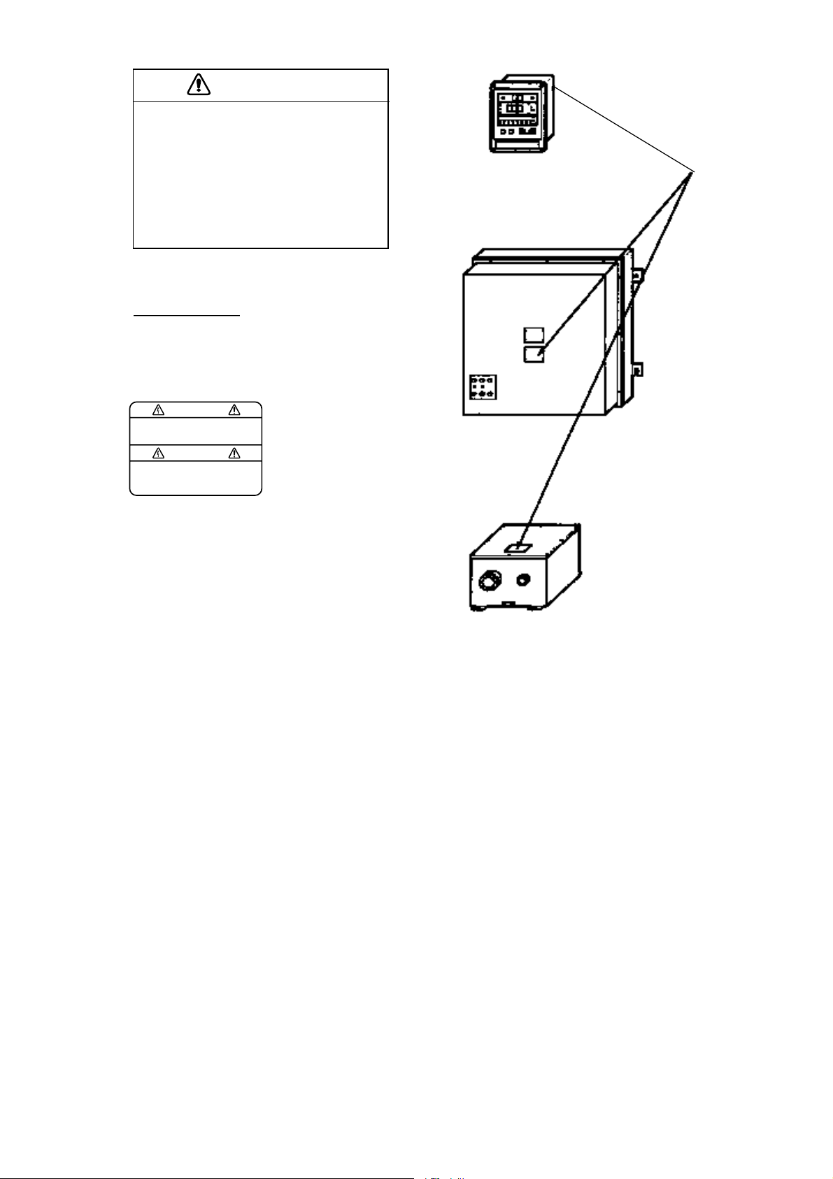
WARNING LABEL
A warning label is attached to the
units shown right. Do not remove the
labels. If a label is missing or is illegible,
contacta FURUNO dealer or agent about
replacement.
WARNING
To avoid electrical shock, do not
remove cover. No user-serviceable
parts inside.
Name: Warning Label (1)
Type: 86-003-1011
Code No.: 100-236-230
MAIN DISPLAY UNIT
DS-500
Warning
label
PROCESSOR UNIT
DS-510, DS-511
TRANSCEIVER UNIT
DS-520
ii
iiiiiiiiiiiiiiiiiiiiiiiiii
Page 5
Page 6
Page 7

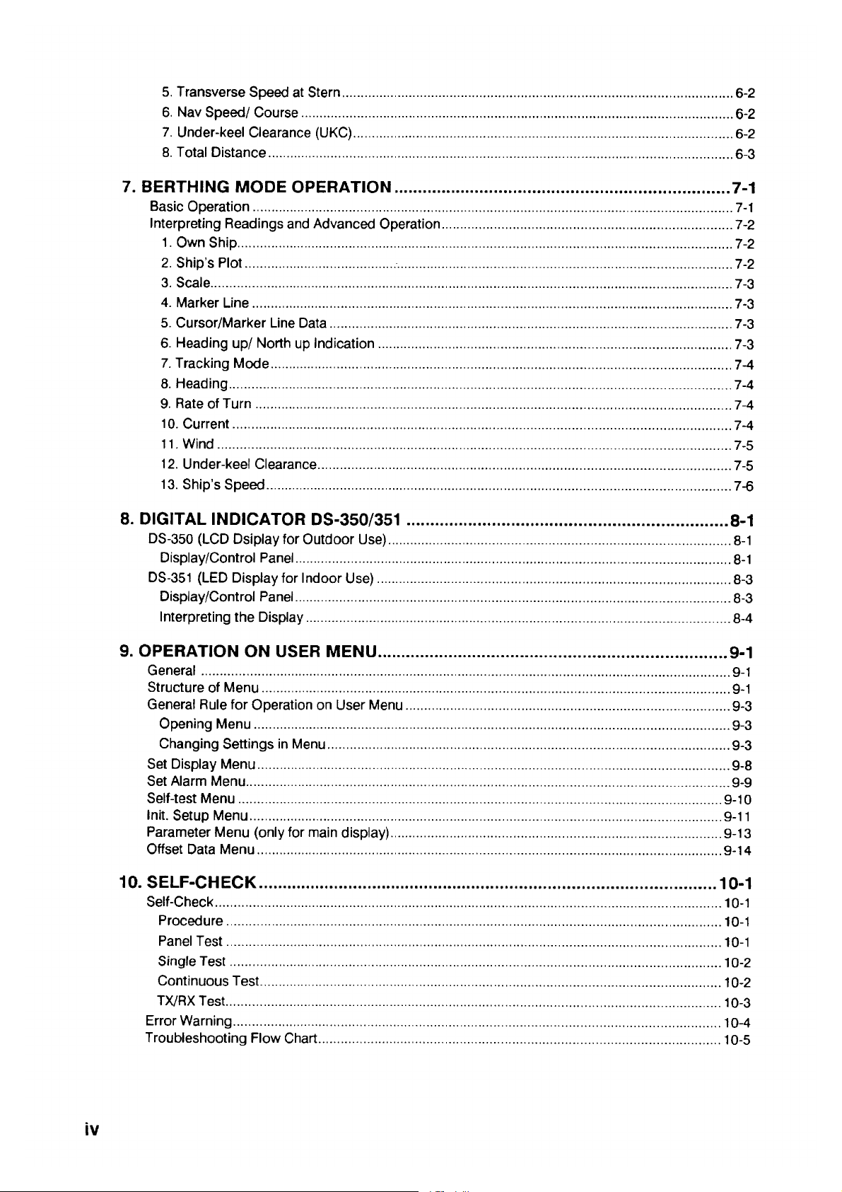
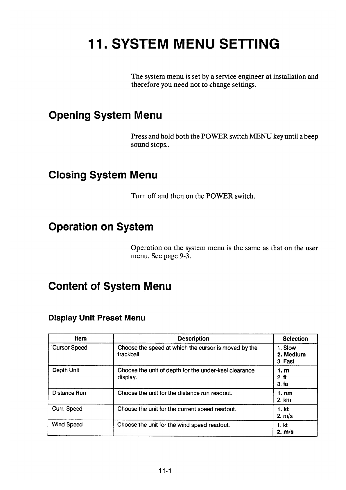
11. SYSTEM MENU SETTING .....................................................................................11-1
Opening System Menu ........................................................................................................................ 11-1
Closing System Menu .......................................................................................................................... 11-1
Operation on System Menu ................................................................................................................. 11-1
Content of System Menu ..................................................................................................................... 11-1
Display Unit Preset Menu ................................................................................................................ 11-2
Display Test Menu ........................................................................................................................... 11-2
Ship Data Menu ............................................................................................................................... 11-2
External Sensor Menu ..................................................................................................................... 11-3
12. REPLACEMENT OF SENSOR IN RATE-OF-TURN GYRO (OPTION) ..............................12-1
13. SPECIFICATIONS OF DOPPLER SONAR DS-30.............................................................13-1
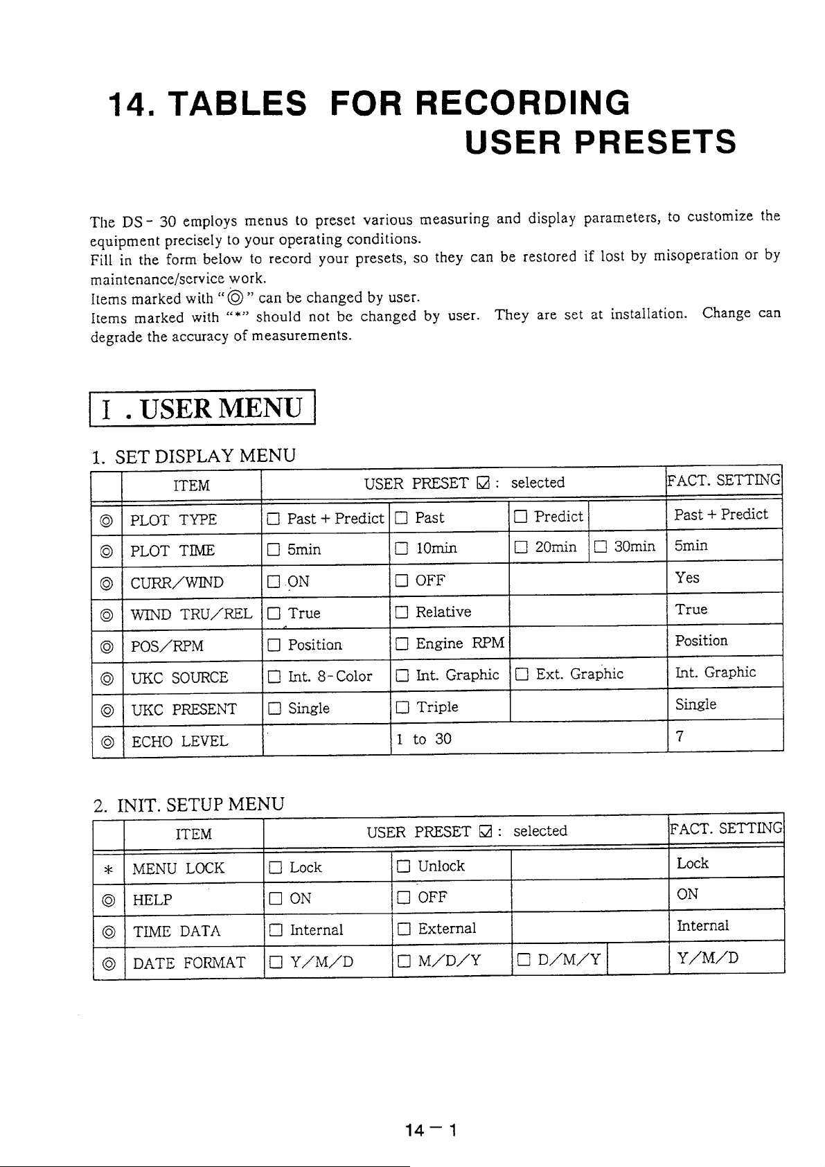
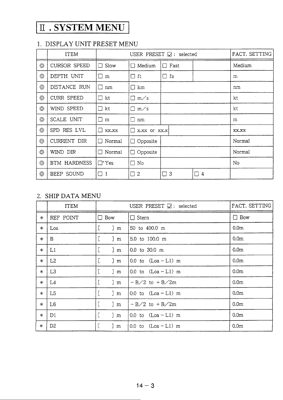
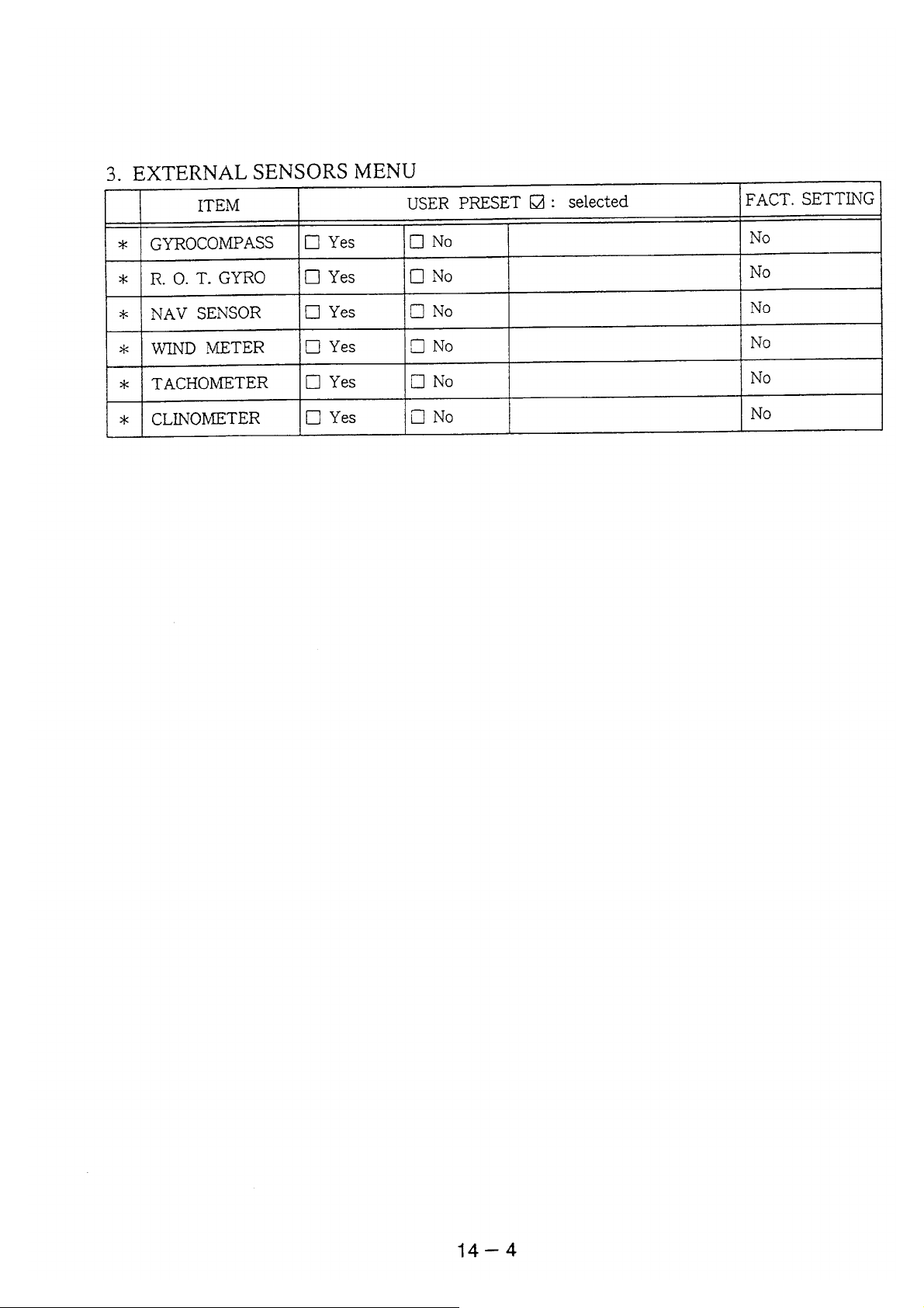
14. TABLES FOR RECORDING USER PRESETS..................................................................14-1
15. DIGITAL INTERFACE (IEC 61162-1 EDITION 2)...............................................................15-1
16. PROGRAM NUMBER ........................................................................................................16-1
Declaration of Conformity
v
Page 8
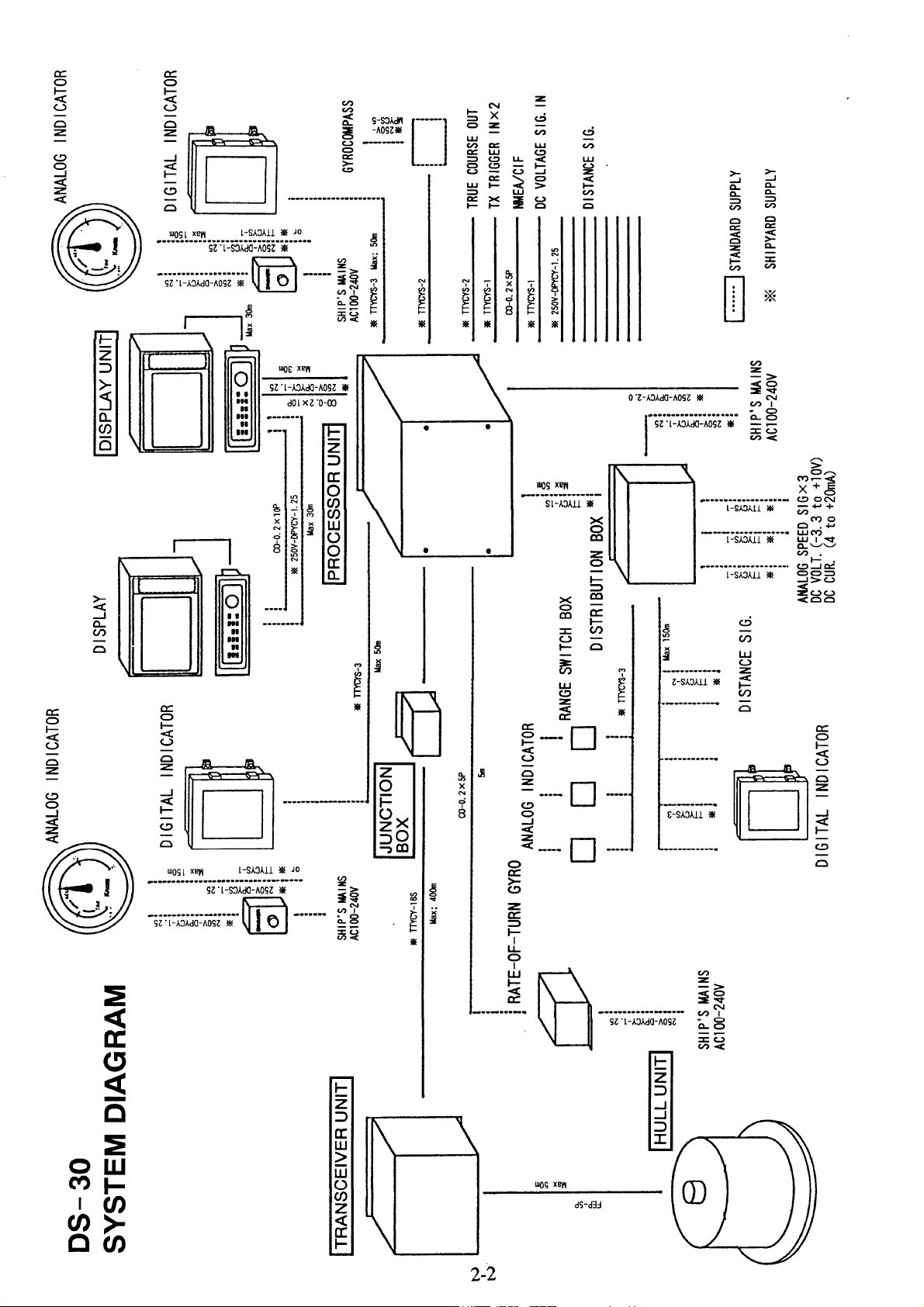
1. GENERAL
The DS-30 is a highly–advanced, precision Doppler Sonar which incorporates FURUNO’s long
established ultrasonic technology.
It provides accurate displays of ship’s speed over a wide range from dead slow to maximum.
Speeds are detected relative to the ground or water both fore-aft and athwarthship. This feature
allows precise docking of mammoth tankers to oil loading/unloading facilities, as well as safe
navigation in narrow channels or straits.
Features
1) High measuring accuracy of ± (0.2% + 0.01 mm/sec) or better for low longitudinal speed, even in
shallow waters with under keep clearance as little as 1 meter, enables close control of speed and
safe berthing and anchoring operations.
2) Ground tracking up to 200 m provides accurate ship’s ground speed in most coastal waters.
3) Single hull unit composition with employment of the rate-of-turn gyro economizes installation
and maintenance costs. (Most other doppler sonars use two hull units: one each for measuring
ship’s transverse speed at the fore and the stern.
4) Rate-of-turn gyro uses optical fibers instead of moving parts, providing high reliability.
5) Logically arranged presentations of information on the color LCD for instant recognition of
ship’s motion and speed together with under-keel clearance, current and wind conditions.
6) GPS navigator connection provides ship’s ground speed at all times.
7) Conforms to the following standards: IMO A.824(19), as amended by MSC.96(72), IMO
A.694(17), IEC 61023, IEC 60945 (3
rd
edition), IEC 61162-1 (2nd edition)
1-1
Page 9
Page 10
Page 11
Page 12
Page 13
Page 14
Page 15
Page 16
Page 17
Page 18
Page 19
Page 20
Page 21
Page 22
Page 23
Page 24
Page 25

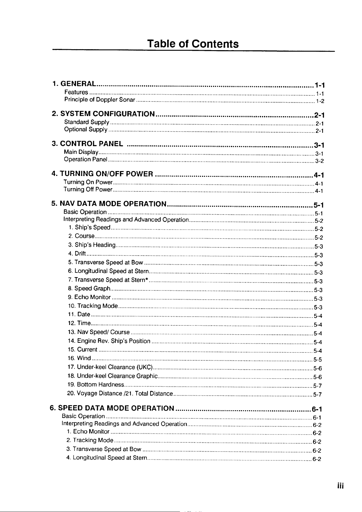
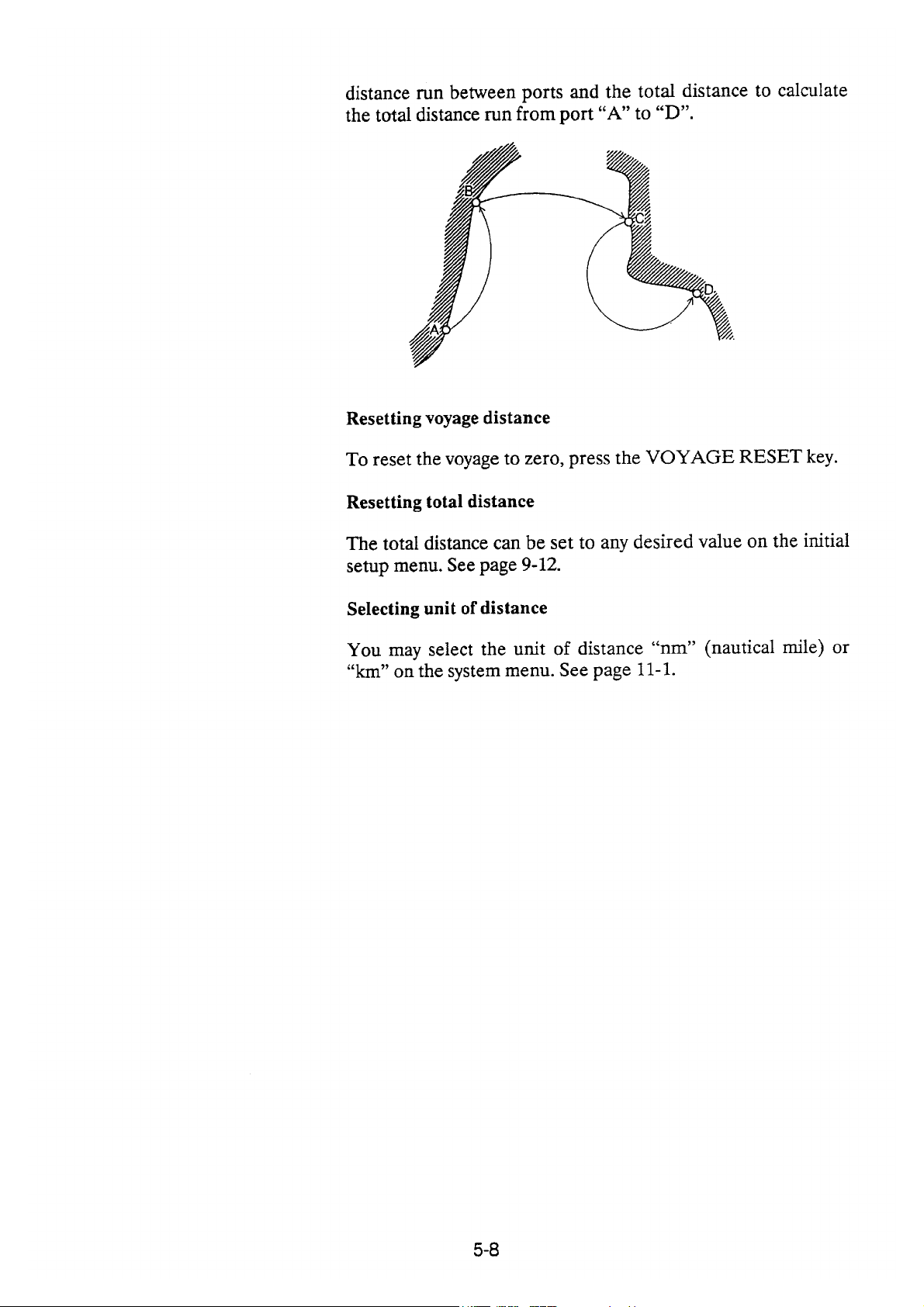
Interpreting Readings and Advanced Operation
In this section, the number beside each header corresponds to the
same number in the illustration of the SPEED DATA MODE screen
on the preceding page. If there is an operation related to a headed
item, the operating procedure is shown.
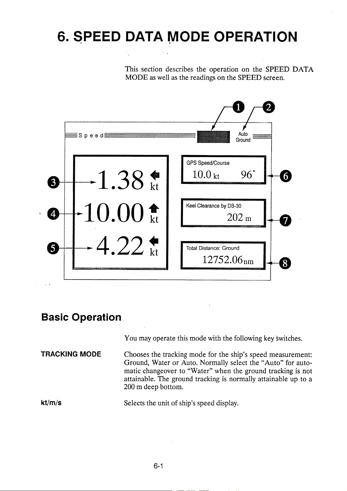
1. Echo Monitor
2. Tracking Mode
3. Transverse at
Speed at Bow
4. Longitudinal
Speed
5. Transverse
speed at Stern
6. Nav Speed/
Course
7. Under-keel
Clearance
(UKC)
Monitors received echoes for the past two minutes, showing echo
type as follows.
Three modes are available:
• Ground tracking echo (green)
• Water tracking echo (blue)
• No echo (background color)
Press the TRACKING MODE key to change the tracking mode.
• Auto: Automatic changeover between ground tracking and water
tracking.
• Ground: Ground tracking
• Water: Water tracking
Value over-the-ground or through-the-water is displayed as
determined by the tracking mode.
Value over-the-ground or through-the-water is displayed as
determined by the tracking mode.
Value over-the-ground or through-the-water is displayed as
determined by the tracking mode
The speed and course measured by a nav sensor (GPS, Loran C)
are displayed. Note that only true course is displayed. If the speed
or course signal is lost the respective indication is erased 30
seconds later.
Selecting nav sensor
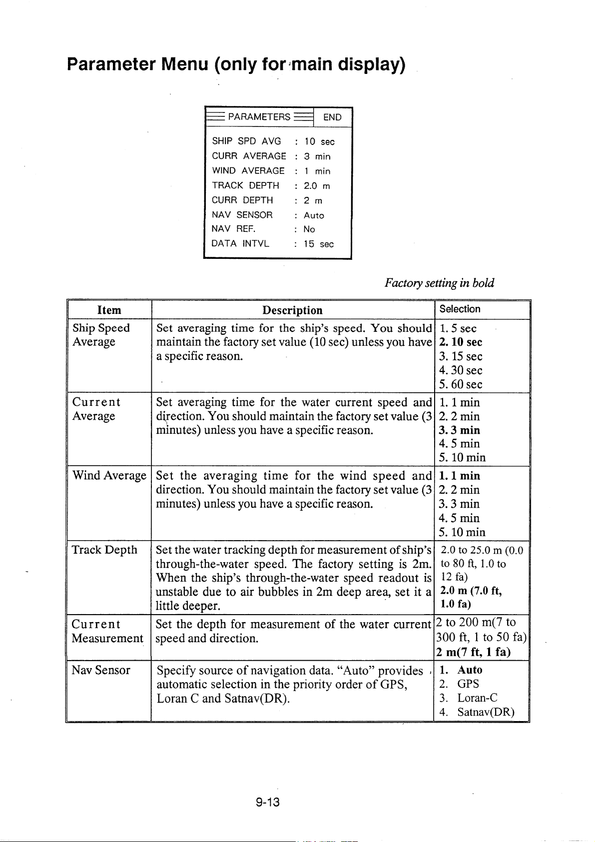
The nav sensor may be selected on the parameter set menu. See
page 9-13.
The under-keel clearance measured by the DS-30 or external
sounder is displayed.
6-2
Page 26

Page 27

Page 28

Page 29

Page 30

Page 31

Page 32

Page 33
Page 34
Page 35
Page 36
Page 37
Page 38
Page 39

Page 40
Page 41

Page 42

Page 43

Page 44

Page 45

Page 46

Page 47

Page 48

Page 49
Page 50
Page 51
Page 52
Page 53
Page 54
Page 55

Page 56
Page 57
Page 58

Page 59

Page 60

Page 61

13. SPECIFICATIONS OF
DOPPLER SONAR DS-30
1. Measurement Range
a. Ship's Speed Bow:
Fore-aft: -10.00 to + 40.00 knots
Port-stbd: -9.99 to + 9.99 knots
Stern with optional Laser gyro:
Port-stbd: -9.99 to + 9.99 knots
b. Speed Measurement Depth
Ground tracking:1 to 200m below hull bottom
Water tracking: 3 to 25m below hull bottom
(Above figures will changed depending on installation conditions
and surrounding water conditions. The measuring accuracy will
be reduced for the depth shallower than 30 m.)
c. Current Direction: 360 degrees (Relative or True with gyro signal input)
Speed: 0.0 to + 9.9 knots
d. Current Measurement Depth
2 to 100m below hull bottom (clearance of more than 8m required)
2. Accuracy
a. Ship's Speed ±0.2% or ±0.01 m/sec for low ship's speed ground tracking.
±1.0% or ±0.1 knots for water tracking mode and high ship's
speed ground tracking (clearance of more than 30m).
~ ±1.0% or ±0.04 m/sec for port-stbd at stern (ship's length 400 m).
[Influence of ship 's inclination and vibration excepted.]
b. Sea Depth (clearance) : ±1.0% or ±0.1m
(at 1500 m/sec of sound velocity and by converting inclined
beams to vertical, without consideration of temperature error.)
c. Distance Signal ±1.0% or ±0.1 nm
d. Current Speed ±2.0% or ±0.2 kt
NOTE 1: The speed error which results from variation of sound velocity by water temperature is
automatically compensated by water temperature measured with temperature sensor mounted on the
transducer: The salinity does not affect accuracy.
NOTE 2: Ship’s static inclination (trim and heel) degrades accuracy by 100(cosθ-1)%
(where θ = angle of inclination). The error caused by this inclination can be corrected by entering trim
and heel angles (-12.5° to + 12.5°) on the OFFSET DATA menu.
NOTE 3: Ship 's rolling/pitching degrades accuracy by 0.2% for ±5° rolling/pitching and 0.65% for ±10°.
The error is 1% when it is 11.5%.
13 – 1
Page 62

3. Display
a. Display Unit 10-inch color LCD
b. Digital Display Unit Wide angle numeric LCD
4. Transmission Frequency
440 kHz
5. Input/Output Si g nal
a. Input/Output Serial signal: 2 ports
b. Input Heading from gyro via Converter AD-100: 1 port
Keying pulse from onboard echo sounding equipment for
minimizing interference: 2 ports
DC signal for wind/speed direction: 1 port
DC voltage signal for main engine revolution: 1 port
c. Output Ship speed (for digital indicator): 3 ports
for distribution box: 1 port
Distance signal: for distribution box: 1 port
for contact closure signal: 8 ports
(200 pulses/nm, forward data only, 30V, 0.2A max.)
for TTL signal (400 p/nm, forward data only): 1 port
Alarm signal: contact signal (30V, 2A max): 1 port
Keying pulse: 1 port
d. IEC 61162-1 2nd edition Input signal: ZDA, GLL,VTG, DBT, RMA, RMC,
format signal HCC*, HDM*, DBK*
Output signal: VDR, VHW, VTG, VLW, VBW, ROT, VCD*
* = Available in NMEA sentence
6. Power Supply
Ship’s Mains 100, 110, 120, 200, 220 or 240 VAC
1ф, 50/60 Hz, 300 VA or less (average), 400 VA or less (peak
value)
7. Environmental Conditions
a. Temperature -15
b. Humidity 95% (at 40°C) max.
(Display unit should be installed indoors)
13 – 2
°C to +55°C
Page 63

Page 64

Page 65
Page 66

Page 67
Page 68
Page 69
15. DIGITAL INTERFACE
(IEC 61162-1EDITION 2)
Output sentences of channel 1, 2 (NMEA/CIF 1, NMEA/CIF 2)
VDR, VHW, VTG, VLW (talker VD), VBW, ROT
Input sentences of channel 1, 2 (NMEA/CIF 1, NMEA/CIF 2)
ZDA, GLL, VTG, DBT, RMA, RMC
Transmission interval
1 s for any sentence
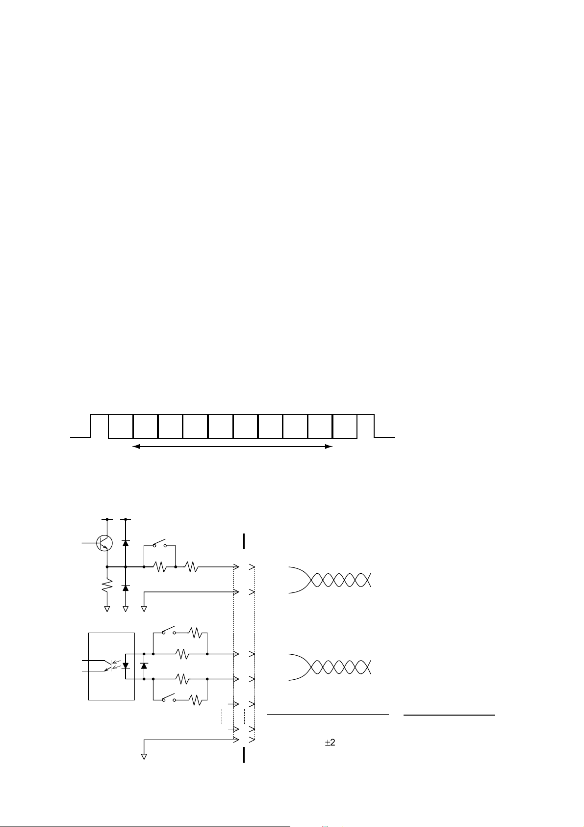
Data transmission
Data is transmitted in serial asynchronous form in accordance with the standard referenced in 2.1 of
IEC 61162-1. The first bit is a start bit and is followed by data bits, least-significant-bit as illustrated
below.
The following parameters are used:
Baud rate: 4800
Data bits: 8 (D7 = 0), parity none
Stop bits: 1
D0 D1 D2 D3 D4 D5 D6 D7
Start
bit
Data bits
Stop
bit
Schematic diagram
CIF: ON
5V
470 ohm
IEC 61162-1 (NMEA 0183) OFF
5V
J2/J3
180 ohm
47 ohm
SRCN6A16/10S
66P3318
1
TXD-A
2
TXD-B
SRCN6A16/10P
CO-0.2X5P
MAX. 25mA
22 ohm
47 ohm
RXD-A
3
47 ohm
4
RXD-B
NC
NC
5
Load requirements as listener
Isolation: Optocoupler
9
Input Impedance: 30 ohms
10
Max. Voltage: ±2.5V
Threshold: 4 mA
22 ohm
15-1
Output drive capability
Max. 25 mA
Page 70

Data sentences (input)
DBT – Depth below transducer
$--DBT,x.x,f,x.x,M,x.x,F*hh<CR><LF>
| | | | | | |
| | | | | | +--------- 4
| | | | +--+----------- 3
| | +--+----------------- 2
+--+----------------------- 1
1. Water depth, feet
2. Water depth, m
3. Water depth, fathoms
4. Checksum
GLL – Geographic position, latitude and longitude
$--GLL,llll.lll,a,yyyyy.yyy,a,hhmmss.ss,A,a*hh<CR><LF>
| | | | | | | |
| | | | | | | +------- 6
| | | | | | +--------- 5
| | | | | +----------- 4
| | | | +---------------- 3
| | +------+----------------------- 2
+---+----------------------------------- 1
1. Latitude, N/S
2. Longitude, E/W
3. UTC of position
4. Status: A=data valid, V=data invalid
5. Mode indicator(see note)
6. Checksum
NOTE Positioning system Mode indicator:
A = Autonomous
D = Differential
E = Estimated (dead reckoning)
M = Manual input
S = Simulator
N = Data not valid
The Mode indicator field supplements the Status field. The Status field shall be
set to V=invalid for all values of Operating Mode except for A=Autonomous and
D=Differential. The positioning system Mode indicator and Status field shall not
be null fields.
MWD – Wind direction and speed
$--MWD,x.x,T,x.x,M,x.x,N,x.x,M*hh<CR><LF>
| | | | | | | | |
| | | | | | | | +--- 5
| | | | | | +--+----- 4
| | | | +--+----------- 3
| | +--+----------------- 2
+--+----------------------- 1
1. Wind direction, 0 to 359 true
2. Wind direction, 0 to 359 Magnetic
3. Wind speed, knots
4. Wind speed, m/s
5. Checksum
15-2
Page 71

MTW - Water temperature
$--MTW,x.x,C*hh<CR><LF>
| | |
| | +--------- 2
+---+----------- 1
1. Temperature, degrees C
2. Checksum
RMA - Recommended minimum specific LORAN-C data
$--RMA,A,llll.lll,a,yyyyy.yy,a,x.x,x.x,x.x,x.x,x.x,a,a*hh<CR><LF>
| | | | | | | | | | | | |
| | | | | | | | | | | | +------- 10
| | | | | | | | | | | +--------- 9
| | | | | | | | | +---+----------- 8
| | | | | | | | +------------------ 7
| | | | | | | +---------------------- 6
| | | | | | +-------------------------- 5
| | | | | +------------------------------ 4
| | | +----+--------------------------------- 3
| +---+-------------------------------------------- 2
+------------------------------------------------------- 1
1. Status: A=data valid, V=blink, cycle or SNR warning
2. Latitude, degrees N/S
3. Longitude, degrees E/W
4. Time difference A, microseconds
5. Time difference B, microseconds
6. Speed over ground, knots
7. Course over ground, degrees true
8. Magnetic variation(see note 1),degree E/W
9. Mode indicator(see note 2)
10. Checksum
NOTE 1 - Easterly variation(E) subtracts from true course
Westerly variation(W) adds to true course
NOTE 2 Positioning system Mode indicator:
A = Autonomous
D = Differential
E = Estimated (dead reckoning)
M = Manual input
S = Simulator
N = Data not valid
The Mode indicator field supplements the Status field. The Status field
shall be set to V=invalid for all values of Operating Mode except for
A=Autonomous and D=Differential. The positioning system Mode indicator
and Status field shall not be null fields.
15-3
Page 72

RMC - Recommended minimum specific GPS/TR ANSI T data
$--RMC,hhmmss.ss,A,llll.lll,a,yyyyy.yyy,a,x.x,x.x,xxxxxx,x.x,a,a*hh<CR><LF>
| | | | | | | | | | | | |
| | | | | | | | | | | | +--- 10
| | | | | | | | | | | +----- 9
| | | | | | | | | +--+------- 8
| | | | | | | | +--------------- 7
| | | | | | | +--------------------- 6
| | | | | | +------------------------- 5
| | | | +---+---------------------------- 4
| | +---+---------------------------------------- 3
| +--------------------------------------------------- 2
+---------------------------------------------------------- 1
1. UTC of position fix
2. Status: A=data valid, V=navigation receiver warning
3. Latitude, N/S
4. Longitude, E/W
5. Speed over ground, knots
6. Course over ground, degrees true
7. Date: dd/mm/yy
8. magnetic variation, degrees E/W
9. Mode indicator(see note)
10. Checksum
NOTE Positioning system Mode indicator:
A = Autonomous
D = Differential
E = Estimated (dead reckoning)
M = Manual input
S = Simulator
N = Data not valid
The Mode indicator field supplements the Status field. The Status field
shall be set to V=invalid for all values of Operating Mode except for
A=Autonomous and D=Differential. The positioning system Mode indicator
and Status field shall not be null fields.
15-4
Page 73

VTG – Course over ground and ground speed
$--VTG,x.x,T,x.x,M,x.x,N,x.x,K,a*hh<CR><LF>
| | | | | | | | | |
| | | | | | | | | +------- 6
| | | | | | | | +--------- 5
| | | | | | +--+----------- 4
| | | | +--+----------------- 3
| | +--+----------------------- 2
+--+----------------------------- 1
1. Course over ground, degrees true
2. Course over ground, degrees magnetic
3. Speed over ground, knots
4. Speed over ground, km/h
5. Mode indicator(see note)
6. Checksum
NOTE Positioning system Mode indicator:
A = Autonomous
D = Differential
E = Estimated (dead reckoning)
M = Manual input
S = Simulator
N = Data not valid
The positioning system Mode indicator field shall not be a null field.
ZDA – Date and time
$--ZDA,hhmmss.ss,xx,xx,xxxx,xx,xx*hh<CR><LF>
| | | | | | |
| | | | | | +--------- 7
| | | | | +----------- 6
| | | | +-------------- 5
| | | +------------------ 4
| | +---------------------- 3
| +------------------------- 2
+--------------------------------- 1
1. UTC
2. Day, 01 to 31(UTC)
3. Month, 01 to 12(UTC)
4. Year(UTC)
5. Local zone hours, 00h to +-13h
6. Local zone minutes, 00 to +59
as local hours
7. Checksum
15-5
Page 74

Data sentences (output)
VBW- Dual ground/water speed
$--VBW,x.x,x.x,A,x.x,x.x,A,x.x,A,x.x,A*hh<CR><LF>
| | | | | | | | | | |
| | | | | | | | | | +--- 11
| | | | | | | | | +----- 10
| | | | | | | | +-------- 9
| | | | | | | +----------- 8
| | | | | | +-------------- 7
| | | | | +----------------- 6
| | | | +-------------------- 5
| | | +------------------------ 4
| | +--------------------------- 3
| +------------------------------ 2
+---------------------------------- 1
1. Longitudial water speed, knots
2. Transverse water speed, knots
3. Status: water speed, A=data valid V=data invalid
4. Longitudial ground speed, knots
5. Transverse ground speed, knots
6. Status: ground speed, A=data valid V=data invalid
7. Stern transverse water speed, knots
8. Status: stern water speed, A=data valid V=data invalid
9. Stern transverse ground speed, knots
10. Status: stern ground speed, A=data valid V=data invalid
11. Checksum
VDR - Set and drift
$--VDR,x.x,T,x.x,M,x.x,N*hh<CR><LF>
| | | | | | |
| | | | | | +--------- 4
| | | | +--+----------- 3
| | +--+----------------- 2
+--+----------------------- 1
1. Direction, degrees true
2. Direction, degrees magnetic
3. Current speed, knots
4. Checksum
VHW - Water speed and heading
$--VHW,x.x,T,x.x,M,x.x,N,x.x,K*hh<CR><LF>
| | | | | | | | |
| | | | | | | | +--------- 5
| | | | | | +--+----------- 4
| | | | +--+----------------- 3
| | +--+----------------------- 2
+--+----------------------------- 1
1. Heading, degrees true
2. Heading, degrees magnetic
3. Speed, knots
4. Speed, km/h
5. Checksum
15-6
Page 75

VLW - Distance travelled through the water
$--VLW,x.x,N,x.x,N*hh<CR><LF>
| | | | |
| | | | +--------- 3
| | +--+----------- 2
+--+----------------- 1
1. Total cumulative distance, nautical miles
2. Distance since reset, nautical miles
3. Checksum
VTG - Course over ground and ground speed
$--VTG,x.x,T,x.x,M,x.x,N,x.x,K,a*hh<CR><LF>
| | | | | | | | | |
| | | | | | | | | +------- 6
| | | | | | | | +--------- 5
| | | | | | +--+----------- 4
| | | | +--+----------------- 3
| | +--+----------------------- 2
+--+----------------------------- 1
1. Course over ground, degrees true
2. Course over ground, degrees magnetic
3. Speed over ground, knots
4. Speed over ground, km/h
5. Mode indicator(see note)
6. Checksum
NOTE Positioning system Mode indicator:
A = Autonomous
D = Differential
E = Estimated (dead reckoning)
M = Manual input
S = Simulator
N = Data not valid
The positioning system Mode indicator field shall not be a null field.
ROT – Rate of turn
$--ROT,x.x,A*hh<CR><LF>
| | |
| | +--- 3
| +----- 2
+-------- 1
1. Rate of turn, deg/min, "-"=bow turns to port
2. Status: A=data valid, V=data invalid
3. Checksum
15-7
Page 76

16. PROGRAM NUMBER
Pub No., Reason for Modification,
Date
OME-72360-R
Modified to conform to IEC 61162-1
Edition 2
2002/4
Software (Prog. No.)
DS-300
CP board 665-0100-007
DS-310
CP board 665-0110-008
FT board 665-0120-100
KL board 665-0130-100
IF board 665-0140-010
DS-320
CP board 665-0160-102
16-1
Page 77

 Loading...