


OPERATOR'S MANUAL
1st WATCH
WIRELESS RADAR
Model
DRS4W
PRODUCT NAME: RADAR SENSOR
www.furuno.com

IMPORTANT NOTICES
Ni-Cd Pb
General
• This manual has been authored with simplified grammar, to meet the needs of international users.
• The operator of this equipment must read and follow the descriptions in this manual. Wrong operation or maintenance can cancel the warranty or cause injury.
• Do not copy any part of this manual without written permission from FURUNO.
• If this manual is lost or worn, contact your dealer about replacement.
• The contents of this manual and equipment specifications can change without notice.
• The example screens (or illustrations) shown in this manual can be different from the screens you
see on your display. The screens you see depend on your system configuration and equipment
settings.
• Save this manual for future reference.
• Any modification of the equipment (including software) by persons not authorized by FURUNO will
cancel the warranty.
• The following concern acts as our importer in Europe, as defined in DECISION No 768/2008/EC.
- Name: FURUNO EUROPE B.V.
- Address: Ridderhaven 19B, 2984 BT Ridderkerk, The Netherlands
Trademark Notices
• All brand and product names are trademarks, registered trademarks or service marks of their respective holders.
• Apple, iPad and iPhone are registered trademarks of Apple, Inc.
• App Store is a registered service mark of Apple, Inc.
• iOS is a registered trademark of Cisco Systems, Inc.
How to discard this product
Discard this product according to local regulations for the disposal of industrial waste. For disposal
in the USA, see the homepage of the Electronics Industries Alliance (http://www.eiae.org/) for the
correct method of disposal.
How to discard a used battery
Some FURUNO products have a battery(ies). To see if your product has a battery, see the chapter on Maintenance. Follow the instructions below if a battery is used. Tape the + and - terminals
of battery before disposal to prevent fire, heat generation caused by short circuit.
In the European Union
The crossed-out trash can symbol indicates that all types of batteries must not be discarded in standard trash, or at a trash site. Take
the used batteries to a battery collection site according to your national legislation and the Batteries Directive 2006/66/EU.
In the USA
The Mobius loop symbol (three chasing arrows) indicates that
Ni-Cd and lead-acid rechargeable batteries must be recycled.
Take the used batteries to a battery collection site according to
local laws.
In the other countries
There are no international standards for the battery recycle symbol. The number of symbols can
increase when the other countries make their own recycle symbols in the future.
Cd
i
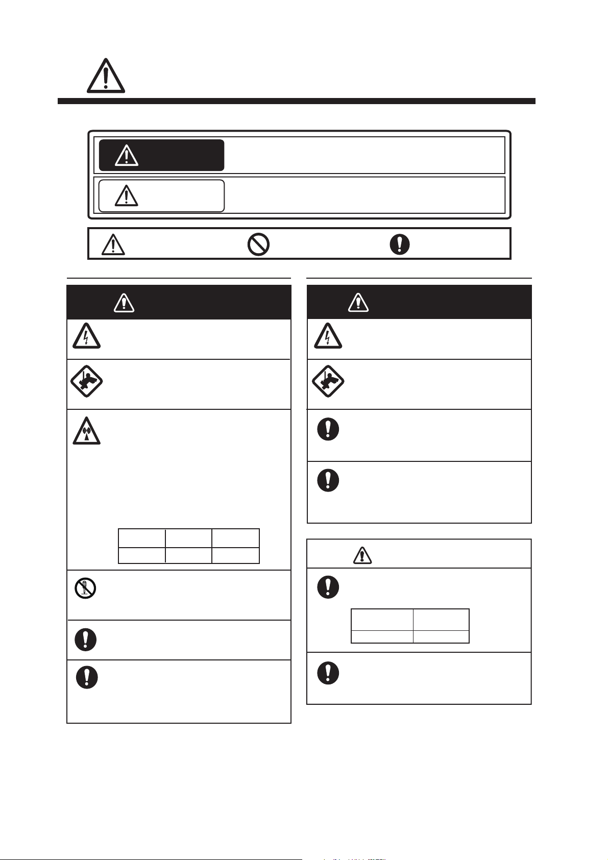
SAFETY INFORMATION
Read these safety instructions before installing or operating the equipment.
WARNING
Indicates a potentially hazardous situation which, if not avoided,
can result in minor or moderate injury.
Warning, Caution
Prohibitive Action
CAUTION
Mandatory Action
Indicates a potentially hazardous situation which, if not avoided,
can result in serious injury or death.
Safety Information for the Operator Safety Information for the Installer
Wear a safety belt and hard hat when
working on the antenna unit.
Serious injury or death can result if
someone falls from the radar mast.
Do not open the equipment.
The installation does not require you
to open the radar sensor.
Be sure the power source is compatible
with the voltage rating of the equipment.
Connection of an incorrect power source
can cause fire or damage the equipment.
Turn off the power at the power source
before beginning the installation.
Fire, electrical shock or serious injury can
result if the power is left on or is applied
while the equipment is being installed.
WARNING
WARNING
ELECTRICAL SHOCK HAZARD
Do not open the equipment.
There are no user servicable parts inside.
The radar antenna emits electromagnetic radio frequency (RF) energy
which can be harmful, particularly to
your eyes. Never look directly into the
antenna aperture from a close distance
while the radar is in operation or
expose yourself to the transmitting
antenna at a close distance.
Distances at which RF radiation levels of
100, 50 and 10 W/m
2
exist are given in
the table below.
100 W/m
2
10 W/m
2
N/A 0.0 m
Do not disassemble or modify the
equipment.
Fire, electrical shock or serious injury can
result.
Wear a safety belt and hard hat when
working on the antenna unit.
Serious injury or death can result if
someone falls from the radar mast.
CAUTION
Observe the following compass safe
distance to prevent interference to a
magnetic compass.
It is recommended that you connect
the sensor to a disconnecting device
(circuit breaker, etc.) to control the
power.
Standard
compass
1.45 m 0.90 m
Steering
compass
50 W/m
2
N/A
Use the proper fuse.
Use of a wrong fuse can damage the
equipment or cause fire.
Do not depend one navigation device
for the navigation of the vessel.
For the safety of vessel and crew, the
navigator must check all aids available to
confirm position.
ii
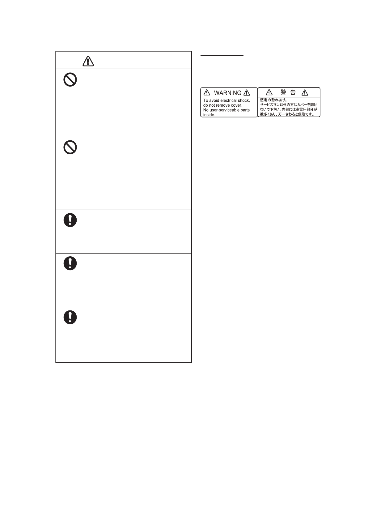
WARNING LABEL
A warning label is attached to the sensor. Do not
remove the label. If the label is missing or
damaged, contact a FURUNO agent or dealer
about replacement.
CAUTION
Do not use high-pressure cleaners
to clean this equipment.
This equipment has the waterproof
rating outlined in the specifications,
at the back of this manual. However,
the use of high-pressure cleaning
equipment can cause water ingress,
resulting in damage to, or failure of,
the equipment.
NEVER handle, transport, or turn the
radome upside down unless the 4 large
flat washers and bolts at the bottom of
the radome are securely in place.
Since the transceiver inside the radome is
only taped to the bottom, the transceiver
can come loose, causing damage to the
RT unit and W-LAN antenna if the 4 bolts
and large flat washers are not in place and
secured.
The radar picture may not be updated
when the WLAN signal is weak.
If the WLAN signal is weak, discontinue
use of the sensor, to prevent trouble
associated with un-updated picture.
Keep the sensor and iOS terminal away
from products which use the 2.4 GHz
wireless LAN radio band (Bluetooth
devices, microwave range, etc.), to
prevent malfunction.
Discontinue use of the sensor if it receives
microwave interference.
The sensor cannot function properly if
there is trouble (equipment trouble, low
battery voltage, etc.) with the iOS
terminal.
For this reason, it is recommended to
keep more than one iOS terminal on
board in case of trouble.
Name: Warning Label (2)
Type: 03-129-1001-3
Code No: 100-236-743
Safety Information for the Operator
SAFETY INFORMATION
iii

TABLE OF CONTENTS
FOREWORD ....................................................................................................................v
1. OPERATION .............................................................................................................1
1.1 System Overview .......................................................................................................... 1
1.2 How to Start, Stop the System ......................................................................................1
1.3 Transmit, Standby .........................................................................................................2
1.4 Display Layout...............................................................................................................2
1.5 Touch Screen Operations ............................................................................................. 3
1.6 Picture Menu .................................................................................................................3
1.7 How to Adjust the Brilliance .......................................................................................... 4
1.8 How to Select a Display Range..................................................................................... 4
1.9 How to Set a Guard Alarm Zone ...................................................................................4
1.10 How to Reduce Rain Clutter.......................................................................................... 5
1.11 How to Measure the Bearing and Range to a Target.................................................... 5
1.12 How to Off Center the Display....................................................................................... 5
1.13 Echo Stretch.................................................................................................................. 6
1.14 Palette ........................................................................................................................... 6
1.15 Echo Color .................................................................................................................... 6
1.16 Picture Format............................................................................................................... 6
1.17 How to Lock the Display (iPhone only) ......................................................................... 6
1.18 How to Take a Screenshot of the Display .....................................................................7
1.19 Settings Menu ...............................................................................................................7
2. MAINTENANCE, TROUBLESHOOTING..................................................................8
2.1 Maintenance..................................................................................................................8
2.2 Replacement of Fuse ....................................................................................................8
2.3 Troubleshooting ............................................................................................................ 9
2.4 Error Messages............................................................................................................. 9
2.5 Replacement of Magnetron........................................................................................... 9
2.6 Self Test ...................................................................................................................... 10
3. INSTALLATION ......................................................................................................11
3.1 Equipment List ............................................................................................................ 11
3.2 Installation Considerations ..........................................................................................11
3.3 How to Install the Radar Sensor ................................................................................. 12
3.4 How to Set up the Radar Sensor ................................................................................ 15
3.4.1 How to start the system .......................................................................................15
3.4.2 Heading, timing adjustment .................................................................................15
3.4.3 Range unit ........................................................................................................... 17
3.4.4 Tuning initialization .............................................................................................. 17
3.4.5 Sector blank......................................................................................................... 17
MENU TREE ..............................................................................................................AP-1
RADIO REGULATORY INFORMATION ...................................................................AP-2
SPECIFICATIONS .....................................................................................................SP-1
PACKING LIST ............................................................................................................ A-1
OUTLINE DRAWING ................................................................................................... D-1
INTERCONNECTION DIAGRAM ................................................................................ S-1
iv

FOREWORD
RADAR SENSOR
DRS4W
Power supply
12/24 VDC
Wireless LAN (WLAN)
2.4 GHz
AC/DC
Adapter
iOS Terminal
(iPad, iPhone)
A Word to the Owner of the
DRS4W
Congratulations on your choice of the FURUNO RADAR SENSOR DRS4W.
Since 1948, FURUNO Electric Company has
enjoyed an enviable reputation for innovative
and dependable marine electronics equipment. This dedication to excellence is furthered by our extensive global network of
agents and dealers.
This equipment is designed and constructed
to meet the rigorous demands of the marine
environment. However, no equipment can
perform its intended function unless installed,
operated and maintained properly. Please
carefully read and follow the recommended
procedures for installation, operation, and
maintenance.
We would appreciate hearing from you, the
end-user, about whether we are achieving our
purposes.
• Two iOS terminals can be connected to the
radar sensor at the same time.
• Guard zone alarm watches for targets entering or exiting an alarm zone.
• Echo stretch lengthens echoes in range
and/or bearing direction.
• Automatic adjustment of sea clutter
(echoes from waves), gain, noise and interference.
• Off center feature lets you look focus on a
specific area ahead of or around your vessel without losing track of position.
• Self test checks the radar sensor for correct
operation.
System Configuration
Thank you for considering and purchasing
FURUNO.
Features
• Complies with wireless LAN standard
• Radar sensor forwards radar echoes to an
• Compatible with the following iOS terminals
• Stylish radome-type radar sensor.
• Echoes shown in green or yellow, or
• 14 ranges from 0.125 to 24 NM.
• Brilliance adjustable to suit lighting condi-
IEEE802.11b.
iPad or iPhone via the 2.4 GHz radio band.
(iOS 6.1.3, 7.0.4 or higher):
• iPhone 5, 5c, 5s, 6 Plus
• iPad 2, 3, 4, Air, Air2, mini, mini2, mini3
multicolor in red, yellow or green, corresponding to strong, medium and weak
echoes.
tions.
Program No.
• 0359329-01.**
** denotes minor modifications.
CE declaration
With regards to CE declarations, please refer
to our website (www.furuno.com), for further
information about RoHS conformity declarations.
v
1. OPERATION
Splash
screen
Searching
radar sensor
Preheating
display
Radar sensor
communciation error!
E0002: Wi-fi communication error
with radar sensor occurred.
Search again
1.1 System Overview
The radar sensor transmits pulses of microwave energy that bounce off any object in
their path. The object returns a tiny part of the
wave's energy to the radar sensor. Radar determines the distance to a target by calculating the time difference between the transmission of a radar signal and the reception of
the reflected echo. The bearing to a target
found by the radar is determined by the direction in which the antenna is pointing when it
emits an electronic pulse and then receives a
returning echo.
The radar sensor forwards the returning
echoes to the iOS terminal (iPhone, iPad), using its wireless LAN module. The radar application in the iOS terminal displays the radar
echoes on the terminal’s display and provides
controls for adjustment of the radar picture.
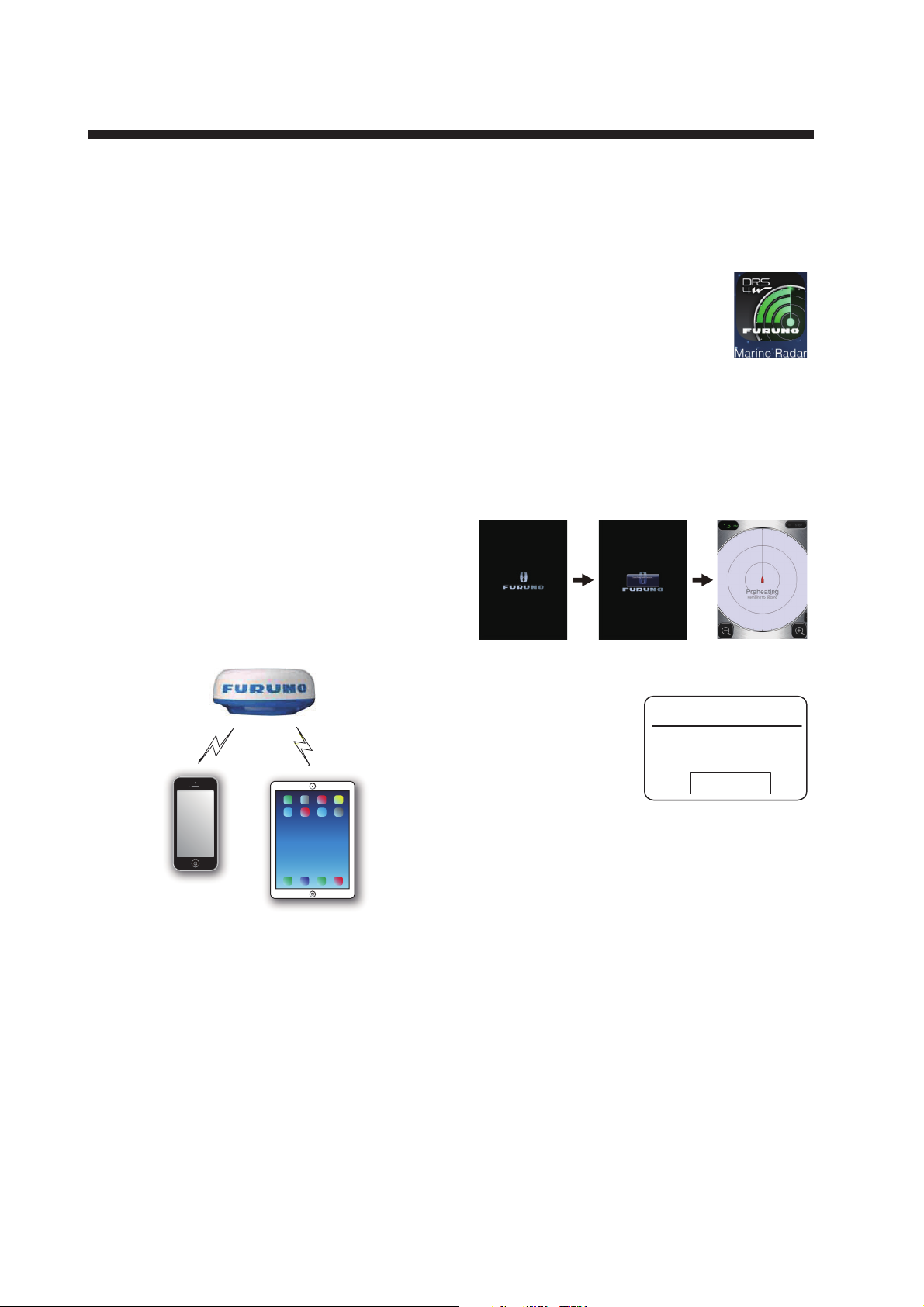
1.2 How to Start, Stop the System
Power the radar sensor to activate the system. Open your iPad
or iPhone terminal and click the
[Marine Radar] application icon
(see right figure).
The splash screen appears for a few moments, then the application tries to connect to
the radar sensor, which normally takes no
more than three seconds. If the connection is
successful, the [Preheating] display appears.
Wireless LAN
iPhone
2.4 GHz
Radar sensor
Wireless LAN
2.4 GHz
iPad
If the connection
failed, the window
shown right appears. Tap the
[Search again] button to try to connect
to the radar sensor. If you cannot connect to
the radar sensor, check for interfering objects
near the sensor and make sure the wireless
LAN function is enabled on your terminal.
The preheating stage, which warms the magnetron (the device responsible for transmitting
radar pulses), takes approx. 90 seconds. The
time remaining until the completion of the preheating is counted down at the center of the
screen. After the completion of the preheating, the STBY display appears.
To deactivate the system, disconnect the radar sensor from the power source.
Note: To connect an iOS terminal to another
DRS4W, reset the application first.
1
1. OPERATION
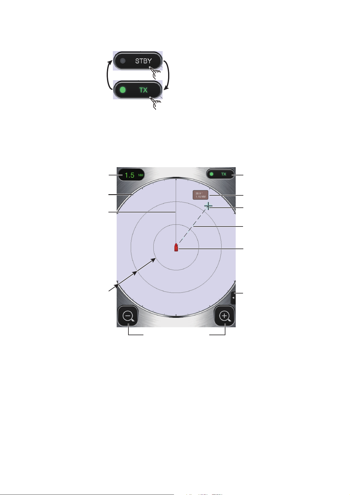
STBY-TX icon
Menu tab*
Fixed range rings
Display range
Heading line
Range selection buttons
Cursor
Own ship mark
Bearing, range box
Bearing scale
Bearing line
* Not provided on iPhone.
1.3 Transmit, Standby
Tap the [STBY-TX]
icon at the top right
corner on the screen
to put the radar in
standby, transmit
state alternately.
When you don’t need the radar, set it to standby to extend the life of the magnetron.
Note: The radar application is set to standby
one minute after you switch to another application.
1.4 Display Layout
The figure below shows all the indications, markers and icons that appear on the iPad radar display. The layout on the iPhone is similar.
2
1. OPERATION
+
1.5 Touch Screen Operations
The table below shows all the basic touch screen operations.
Operation Action Operation Action
Tap • Open, close
menus.
• Operate various buttons.
Double
tap
• Cancel off
center display.
Drag • Move the cur-
Pinch in,
Pinch out
sor.
• Move slider bar
in menus.
• Off center the
display.
• Select display
range.
Long
push
(approx.
2 sec.)
• Display the
cursor.
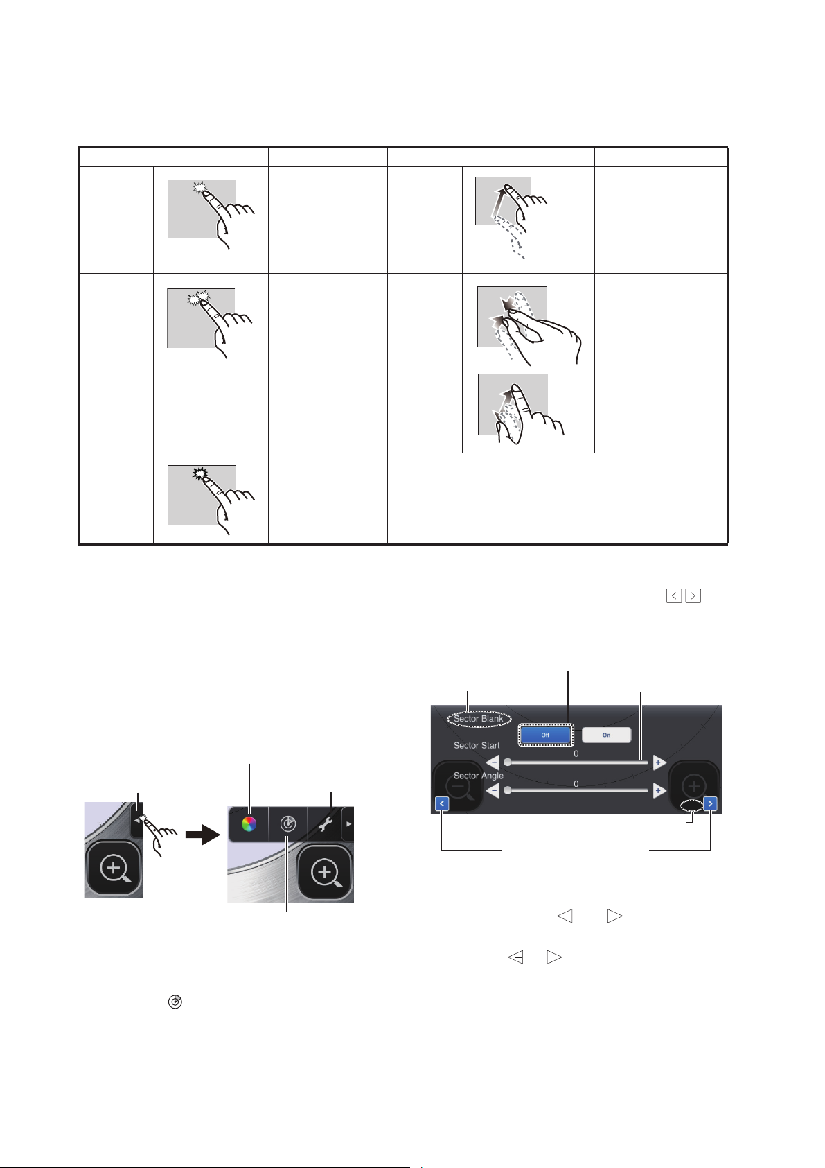
1.6 Picture Menu
This sensor has three menus: Picture, Color,
and Settings.The Picture menu contains the
most frequently used radar functions.
1. iPad: Tap the Menu tab at the right side of
the screen to show the menu.
Color menu icon
Menu tab
Settings menu icon
3. Use the page selection buttons ( ) to
/
browse the items of the menu. For example, select [Sector Blank].
Function button
Item name
Item no./Item total
Page selection buttons
Slider bar
3 / 3
4. The [Picture] menu has several types of
controls for adjustment.
Picture menu icon
Slider bar with and buttons: Drag
+
the slider bar to adjust the item selected.
iPhone: Tap anywhere to show the
menu.
2. Tap the ( ) icon to activate the [Picture]
menu.
Use the or button to fine tune the
setting.
Function buttons: Tap the appropriate
button to select the function labeled on
the button.
5. To close the menu, tap anywhere outside
the menu area.
3
1. OPERATION
Decrease the range
(zoom in)
Increase the range
(zoom out)
1.7 How to Adjust the Brilliance
The brilliance can be adjusted to suit lighting
conditions. Open the menu then tap the ( )
icon. Drag the slider bar to adjust the brilliance.
1.8 How to Select a Display Range
The range selects how far you want the radar
to “see”. The range selected automatically determines the range ring interval, the number
of range rings and pulse repetition rate. The
current range is shown at the top left corner
on the screen.
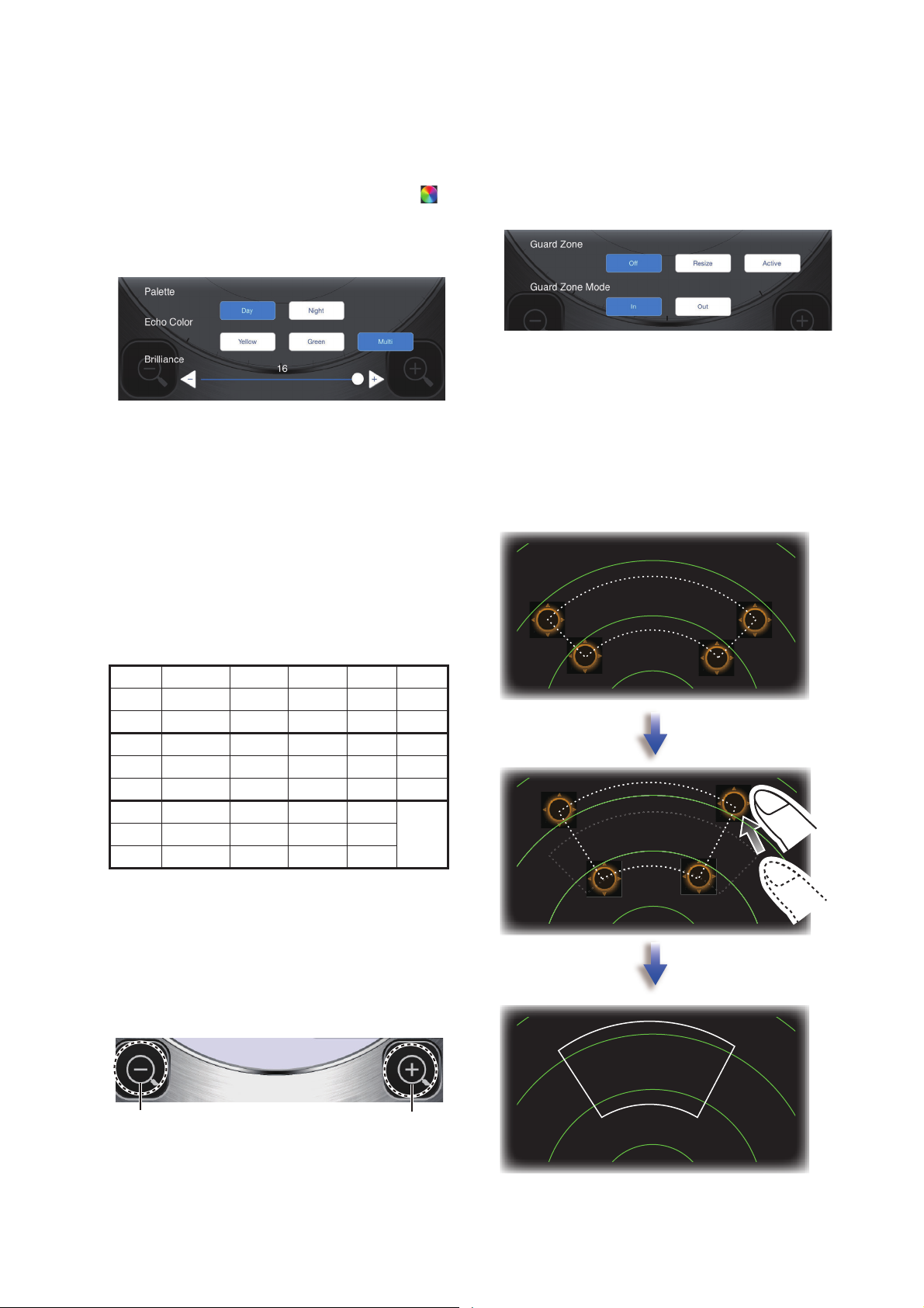
1.9 How to Set a Guard Alarm Zone
Follow below steps to set a guard alarm zone.
1. Tap the picture menu icon.
2. Tap [Resize] menu.
3. Four circles appear at the four corners of
the guard zone.
4. Drag the circles to set the guard zone.
5. Tap [Active] menu.
6. The dotted lines turn to solid lines and
guard zone appears.
R 0.125 0.25 0.5 0.75 1
FRR 0.0625 0.125 0.125 0.25 0.25
NR 2 2 4 3 4
R1.5 2 3 46
FRR 0.5 0.5 1 1 2
NR 3 4 3 4 3
R 8 12 16 24
FRR 2 3 4 6
NR 4 4 4 4
R: Display range, FRR: Fixed range ring
interval, NR: Number of fixed range rings
To select a display range, tap the range selection buttons at the bottom right and left corners. Alternatively, you can pinch in or pinch
out within the display area.
4
1. OPERATION
Guard Zone Mode
[In]: When the targets enter a target alarm
zone, the alarm occurs.
[Out]: When the targets exit a target alarm
zone, the alarm occurs.
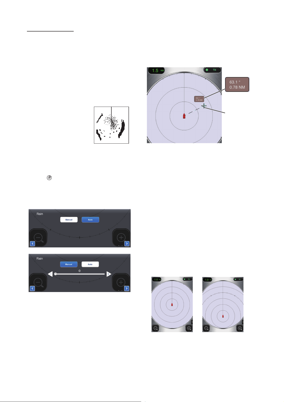
1.10 How to Reduce Rain Clutter
The antenna picks up rain
clutter (rain, snow, or hail)
in the same manner as
normal targets, as in the
right figure. When rain
clutter masks targets, use
the [Rain] control to reduce the clutter. The higher the setting the
greater the reduction of rain clutter
To adjust the rain clutter, open the menu then
tap the ( ) icon. Select the [Rain] screen.
Tap the [Manual] or [Auto] button. For manual
adjustment, drag the slider bar to reduce the
rain clutter.
center of the target. See the bearing and
range to the target in the [Bearing/Range]
box, which is to the side of the cursor. After
several seconds, the cursor is erased from
the screen.
Bearing,
range to
cursor
Cursor
Note: A slight difference exists between finger position and cursor position in order to
see the cursor while dragging it.
1.12 How to Off Center the Display
1 / 3
Automatic adjustment
1 / 3
Manual adjustment
1.11 How to Measure the Bearing and Range to a Target
Own ship position, or sweep origin, can be
displaced manually or automatically to expand the view without switching to a longer
range. The maximum amount of shift is 75%
of the range in use.
To off center the display, drag the own ship
mark to the position you want to make the
screen center. To return to the normal display,
double tap the display area.
Normal display Off centered display
The bearing and range from own ship to a target can be measured with the cursor. Long
push the screen to show the cursor, which is
a cross (+). Drag the cursor to put it on the
5

1. OPERATION
Echo
Brg dir.
Brg dir.
Rng
dir.
Echo stretch
OFF
Echo stretch
Low
Echo stretch
High
1.13 Echo Stretch
On long ranges, target echoes tend to shrink,
making them difficult to see. To enhance target video on long ranges, use the echo stretch
feature to lengthen echoes in the bearing
and/or range direction.
Open the menu then tap the ( ) icon. Select
the [Echo Stretch] screen. Select [Low] to
lengthen echoes in the bearing direction;
[High] to lengthen echoes in both the bearing
and range directions.
1.15 Echo Color
Echoes can be shown in yellow, green, or
multicolor. Multicolor paints each radar echo
in a color according to its strength, in red, yellow or green, corresponding to strong, medium and weak echoes. Open the menu then
tap the ( ) icon. Select the color desired at
[Echo Color].
1.16 Picture Format
You can show the radar picture in landscape
or portrait format. Rotate your terminal to
change the format.*
* Only Portrait display is available on iPhone.
2 / 3
1.14 Palette
The palette feature changes the color of the
background, characters, range rings and
heading line to suit the time of day, daytime or
nighttime.
Open the menu then tap the ( ) icon. Select
[Day] or [Night] as appropriate.
Item
Background White Black
Characters Gray Red
Rings Gray Red
Heading line Gray Red
Day Night
Color
1.17 How to Lock the Display (iPhone only)
Tap the screen of iPhone. Tap the key icon of
menu tab to lock the display. Tap the key icon
of menu tab again to unlock.
Note: The display lock is activated only when
the radar application is shown on the top of
iPhone or iPad. The display lock is deactivated when an alarm occurs.
6

1. OPERATION
(Version no. appears here)
Full screen ONFull screen OFF
1.18 How to Take a Screenshot of the Display
You can take a screenshot of the radar display, and save it to the Photos folder in your
terminal. Push the Home and Power buttons
together. You should hear the camera shutter
sound.
1.19 Settings Menu
The [Settings] menu contains items that once
preset do not require frequent adjustment.
Open the menu then tap the ( ) icon to open
the [Settings] menu.
[Range Ring]: The range rings are the concentric circles about own ship position, and
they function to provide an estimate of the
range to a target. You can turn the rings on or
off here.
[Own Ship Mark]: The own ship mark is
shown at the display center and indicates
your current position. You can turn the mark
on or off here.
Initial Settings menu
Sound
Vibration
Units
Tune Initialize
[Sound]: Turn on/off the alarm sound.*
nm
>
Display Settings menu
[Full Screen]: Turn the full screen display on
or off.
* When iPhone or iPad is set on mute, there is
no alarm sound.
[Vibration]: Turn on/off the alarm vibration.*
* For iPhone only.
[Units]: Select the unit of range measurement, nm or km.
[Tune Initialize]: Automatically tune the radar
receiver. See the chapter on installation.
Installation Settings menu
The items in this menu are mainly intended for
the serviceman. See the chapter on installation.
Self Test
Tests the radar sensor and radar application
for proper operation. See the chapter on
Maintenance.
Operation Guide
Operator’s guide to the basic functions of this
radar.
Version
Shows the software version no.
7

2. MAINTENANCE,
WARNING
DO NOT OPEN THE SENSOR.
Electrical shock hazard
There are no user-serviceable parts
inside. Only qualified personnel are
allowed to work inside the equipment.
WARNING
TROUBLESHOOTING
2.1 Maintenance
Regular maintenance is important for good
performance. Check the points mentioned below every 3 to 6 months to keep the radar sensor in good working order. Observe the safety
instructions at the front of this manual when
working on the mast.
Check point Action
Check fixing
bolts for corrosion and if tightly
fastened.
Check radome
for cracks,
foreign material.
Tighten loosened bolts.
Replace corroded bolts.
Coat new bolts with marine
sealant.
If a crack is found, repair it
temporarily with a small
amount of sealing compound or adhesive. Bring
the unit to your dealer for
permanent repairs.
Foreign material on the
radome can cause a
considerable drop in sensitivity. Remove foreign
material with a freshwatermoistened cloth. Do not
use commercial cleaners to
clean the sensor; they can
remove paint and markings
or deform the plastic.
2.2 Replacement of Fuse
The 5A fuse (Type: FGBO 250V 5A PBF,
Code No.: 000-155-840-10) in the fuse holder
on the power cable protects the radar sensor
from overcurrent and equipment fault. If you
cannot turn on the power, check the fuse to
see if it has blown. If the fuse has blown, find
the reason before you replace the fuse. If the
fuse blows again after the replacement, contact your dealer for advice.
Use the proper fuse.
Use of the wrong fuse can damage the equipment or cause fire.
NOTICE
Do not apply paint, anti-corrosive sealant
or contact spray to coating or plastic parts.
Those items contain organic solvents that can
damage coating and plastic parts.
8

2. MAINTENANCE, TROUBLESHOOTING
2.3 Troubleshooting
The table below provides simple troubleshooting procedures that the user can follow
to restore normal operation. If you cannot restore normal operation, contact your dealer
for advice.
Trouble Remedy
The power
cannot be
turned on.
The power is
on but nothing appears
on the
display.
The display
freezes.
You cannot
connect to
the wireless
LAN but you
can see the
host on the
terminal.
• Check if the power cable is
connected to the power
source and the power
source is on.
• Check the power cable for
damage.
• Check if the fuse has blown.
Try adjusting the brightness
with [Brightness] in the
[Settings] menu in your terminal, or [Brilliance] in the radar
application.
• Restart the application.
• Reset your terminal.
• Switch between standby
and transmit.
• Restart the application.
• Check the WLAN settings in
your terminal.
• Restart your terminal.
2.4 Error Messages
Error messages are shown to alert you to radar sensor problems. The table below shows
the error messages and accompanying message numbers and check points. These alerts
appear in the background; no notification is
given.
Message
"No radar
sensor
found!"
"Radar sensor communication error!"
"Radar sensor signal
error!"
“Guard zone
area is out of
the current
range scale!”
“Target
Alarm!”
Message no. and
check point
E0001: Please check Wi-Fi
connection setup and if power is applied to radar sensor.
E0002: Wi-Fi communication
error with radar sensor occurred.
E0003: Heading pulse from
radar sensor is not detected.
Please check radar sensor
condition.
E0004: Video signal from radar sensor is not detected.
Please check radar sensor
condition.
E0005: Please adjust the
range scale or move the
guard zone closer to your location.
Target(s) entered the guard
zone.
Target(s) exited the guard
zone.
2.5 Replacement of Magnetron
The life expectancy of the magnetron is approx. 5,000 hours. The effectiveness of the
magnetron decreases over time, causing lower-than-normal signal strength and loss of
echoes. If you feel the signal strength is low,
contact your dealer about replacement of the
magnetron.
Name Type Code no.
Magnetron E3571 000-126-646
9

2.6 Self Test
WLAN=Wireless LAN
Actual value appears in place of “x”.
WLAN FW version
WLAN Status
WLAN Channel
WLAN Power
15dBm
03593929-xx.xx
03593930-xx.xx
0359313-xxxxxxx-xx
172.31.x.xx
172.31.x.xx
xx-xx-xx-xx-xx-xx
x
The self test is for use by the service technician to check the equipment. However, the
user can do the test to support the service
technician.
1. Open the menu then tap the ( ) icon.
2. Tap [Self Test] to do the self test.
2. MAINTENANCE, TROUBLESHOOTING
Scroll
The result for [ROM], [RAM], [WLAN Status]
and [Antenna Status] is [OK] or [NG] (No
Good). If [NG] appears for an item, try the test
again, or restart the radar sensor. If [NG] appears again, contact your dealer for advice.
10

3. INSTALLATION
3.1 Equipment List
Name Type Code No. Qty Remarks
Standard supply
Radar Sensor RSB-126-103 - 1
Installation
Materials
Documents OME-36360 - 1 Operator’s Manual
Spare Parts SP03-17801 001-265-910 1 5A fuse, 2 pcs.
Optional supply
Radome Mount OP03-209 001-078-350 1 Mast mounting bracket for sailboat
CP03-35800 000-024-974 Select
CP03-35810 000-024-975 Power cable assy., 15 m
CP03-35820 000-024-976 Power cable assy., 20 m
CP03-35830 000-024-977 Power cable assy., 30 m
CP03-35701 001-265-920 1 - Hex bolt*(M10u25), 4 pcs.
MDC-36360 - 1 C-ROHS list
E32-01314 - 1 Template
E32-01401 - 1 SSID, password information
E32-01405 - 1 Notes on usage
one
Power cable assy., 10 m
- Flat washer (M10 SUS304), 4 pcs.
- Spring washer (M10 SUS304), 4 pcs.
*For use if thickness of platform is
6–10 mm.
3.2 Installation Considerations
General considerations:
• Do not apply paint, anti-corrosive sealant or contact spray to coating or plastic parts. Those items
contain solvents that can damage coating and plastic parts.
• The radar sensor has no power switch. Therefore, it is recommended that you connect the sensor
to a disconnecting device (circuit breaker, etc.) to control the power.
Sensor placement:
• The radar sensor uses the 2.4 GHz wireless LAN radio band to forward radar echoes to the iOS
terminal. Separate the sensor well away from products which also use this band (microwave
range, Bluetooth devices, etc.) to prevent mutual interference.
• Install the radar sensor on the hardtop, radar arch or on a mast on an appropriate platform. (For
sailboats, a “radome mount” is optionally available for fixing the sensor to a mast.) Place the sensor where there is a good all-round view with, as far as possible, no part of the ship’s superstructure or rigging intercepting the scanning beam. Any obstruction will cause shadow and blind
sectors. Be sure there are no metallic objects near the antenna. See the next page for typical
placement on a sailboat and powerboat.
• Observe the wireless LAN communication range noted in the illustration on the next page.
• In order to reduce the chance of picking up electrical interference, avoid where possible routing
the power cable near other electrical equipment onboard. Also, avoid running the cable in parallel
with other power cables.
• Select a location that does not allow water to accumulate at the base of the sensor.
• A magnetic compass will be affected if the radar sensor is too close to the compass. Observe the
compass safe distances mentioned on page ii to prevent interference to a magnetic compass.
11

Radar
45°
60°
Weak signal
area
30°
30°
Location and wireless LAN communication range
Typical installation on a sailboat, power boat
Strong signal area
Strong signal area
Weak signal
area
Strong signal area
Weak signal
area
Weak signal
area
Weak signal
area
sensor
Radar
sensor
Installation on a sailboat
3. INSTALLATION
Radar
sensor
Radar sensor
Installation on a powerboat
3.3 How to Install the Radar Sensor
Determine the suitability of the mounting location BEFORE permanently mounting the sensor. Incoming and outgoing signals may
overlap one another depending on the shape
of the vessel, preventing communication between the terminal and the sensor. Set the
sensor on the selected location and connect
the sensor to the power source. Turn on the
sensor. Open the terminal, turn on the radar
application and try to connect the terminal to
the sensor (see section 3.4.1 for how to start
the system). If the connection is successful,
change the range to check if the sensor receives your command. Check that the picture
is updated with each sweep. Some trial and
error may be necessary to find a suitable location.
Installation on a platform
1. Remove the mounting hardware at the
bottom of the radar sensor - four each of
hex bolts (M10u20), spring washers and
flat washers. Save the spring washers
and flat washers to use them to fasten the
radar sensor to the platform, at step 4. If
the thickness of the platform is 5 mm or
less, also save the bolts.
STERN
Power
cable
Flat washer
Spring washer
Hex bolt
BOW
12

3. INSTALLATION
Flat
washer
Sensor base assy.
Platform
Hex bolt
(See below.)
Apply marine
sealant.
L
Spring
washer
Platform thickness and bolt to use
Platform
thickness
Bolt to use
5 mm or less
M10×20 (Supplied, prefastened to radome.)
6 - 10 mm
M10×25 (Supplied.)
Over 10 mm
Use bolt where the length of “L” above is
15 mm. Supply locally.
2. Construct a platform (steel or aluminum)
referring to the outline drawing and the
mounting template. Fasten the platform to
the mounting location. The holes in the
platform must be parallel with the fore and
aft line.
3. Put the radar sensor on the platform with
the bow mark (U) on sensor aligned with
the bow.
4. Use hex bolts*, flat washers and spring
washers (removed at step 1) to fasten the
radar sensor to the platform. The torque
for the bolts must be 19.6 to 24.5 N•m.
*See the figure below to determine bolt
length to use.
Note: NEVER handle, transport, or turn
the radome upside down unless the
4 large flat washers and bolts at the
bottom of the radome are securely in
place.
Since the transceiver inside the radome is
only taped to the bottom, the transceiver
can come loose, causing damage to the
RT unit and W-LAN antenna if the 4 bolts
and large flat washers are not in place
and secured. For this reason, NEVER
handle, transport, or turn the radome upside down unless the 4 bolts and large flat
washers are secured.
Default position of bolt and washer
Large flat washer
Small flat
washer
Spring washer
Screw
hole
5. Connect the supplied power cable to the
sensor. Observe the guidelines for laying
the power cable shown on this page.
6. Connect the power cable to the power
source.
1: Red
2: Braid
3: Blue
Power cable
pin assignment
Guidelines for laying the power cable
• The connectors must not strike any part of
the vessel by wind, etc.
• The load applied to the connectors must
not be more than its own weight.
13

3. INSTALLATION
Loop cable and tie
loop with cable ties.
Mounting plate
Support
plate (1)
Support
plate (2)
Bracket (1)
Fixing
plate
M8×20
ASSEMBLED
RADOME MOUNT
M8×20
M8×20
M4×12
How to assemble the radome mount
Rivet
M10×25
How to fasten the sensor to the radome mount
Bracket (2)
• If the cable is passed through a mast on a
sailboat, be sure the cable does not touch
ropes (sheet, halyard, etc.).
• Do not fasten the cable to the hull.
• The cable must be fixed so no tension is applied to the connectors. To prevent tension,
create a loop in the cable close to the sensor and tie the loop with cable ties, as in the
figure below.
• Wrap the junction of the connectors with
self vulcanizing tape for waterproofing.
• Fasten the cable to the mast, etc. at the
neck of each connector with a cable tie.
How to assemble the bracket
1. Fasten the fixing plates to brackets (1)
and (2) with four M8u20 hex bolts.
2. Fit brackets (1) and (2) loosely with support plates (1) and (2) using four M4u12
hex bolts, so that the gap between the
brackets can be adjusted.
3. Place the mounting plate on the bracket
and fix it loosely with four M8u20 hex
bolts.
How to fasten the bracket to the mast
1. Drill eight holes of 6.5 mm diameter in the
mast and fix the bracket with eight stainless steel rivets (local supply) of 6.4 mm
diameter.
2. Tighten the bolts on the bracket.
3. Fasten the radar sensor to the bracket.
Connect the power cable to the power source,
observing the guidelines for laying the power
cable shown on this page.
Installation with the radome mount
The optional radome mount lets you fasten
the radar sensor to a mast on a sailboat.
Name, Type: Radome Mount, OP03-209
Code No.: 001-078-350
Name Type Code No. Qty
Mounting
plate
Support
plate (1)
Support
plate (2)
Bracket
(1)
Bracket
(2)
Fixing
plate
Hex bolt
w/washer
03-0189001-0
03-0189005-0
03-0189006-0
03-0289101-1
03-0289101-2
03-0289103-1
M8u20
SUS304
100-206740-10
100-206780-10
100-206790-10
100-206811-10
100-206812-10
100-206831-10
000-162955-10
1
1
1
1
1
2
8
Hex bolt
w/washer
M4u12
SUS304
000-162956-10
4
14

3. INSTALLATION
Splash
screen
Searching
radar sensor
Preheating
display
3.4 How to Set up the Radar Sensor
Before you can set up and use the radar sensor, download and install the free application
[Marine Radar] from the App Store. The application is common to both the iPad and the
iPhone.
Set up the radar as shown in this section, in
the order given.
An insert sheet requests you to attach the
supplied SSID and password label to the insert sheet. Attach the label to the sheet, and
store the sheet in a safe place for future reference.
3.4.1 How to start the system
Power the sensor. Open your
iOS terminal, then turn on the
wireless LAN function (in the
[Settings] menu) if it is not already on. Tap the [Marine Radar] application (see right figure, appearance
subject to change) in your terminal.
3.4.2 Heading, timing adjustment
How to open the Installation Settings
menu
To adjust the heading or timing, you must first
open the [Installation Settings] menu.
1. Open the menu, Settings menu:
1) iPad: Tap the menu tab at the bottom
right corner to open the menu.
iPhone: Tap anywhere to open the
menu.
2) iPad, iPhone: Tap the Settings menu
icon ( ) to show the Settings menu.
Settings
Menu tab
How to open the Settings
menu on the iPad
2. Tap [Installation Settings]. You are asked
to input the pass code.
menu icon
The splash screen appears for a few moments, then the application tries to connect to
the radar sensor, which normally takes no
more than three seconds. If the connection is
successful, the [Preheating] display appears.
If the connection could not be made, an error
message appears. Tap the [Search again]
button to try to connect to the sensor. If the
application cannot connect to the sensor,
check to see if the wireless LAN function is
enabled on your terminal.
After the preheating is completed, which
takes approx. 90 seconds, the radar goes into
standby. Tap the STB-TX icon at the top right
corner on the display to transmit.
3. Use the software keyboard to enter 1234.
4. Tap [Back] twice to close the menu and
return to the radar display.
15

3. INSTALLATION
/
Heading line
Heading line
Target
Correct
Target pushed
inward
Target pushed
outward
Heading alignment
You have mounted the radar sensor facing
straight ahead in the direction of the bow.
Therefore, a small but conspicuous target
dead ahead visually should appear on the
heading line (zero degrees).
In practice, you will probably observe some
small error on the display because of the difficulty in achieving accurate initial positioning
of the sensor. The following adjustment compensates for this error.
1. Open the menu, Picture menu:
1) iPad: Tap the menu tab at the bottom
right corner to open the menu.
iPhone: Tap anywhere to open the
menu.
2) iPad, iPhone: Tap the ( ) icon to
open the Picture menu.
3. Visually identify a suitable target (for example, ship or buoy) at a range between
0.125 to 0.25 miles.
4. Point your boat’s bow directly toward the
target selected at step 3.
5. Locate the target selected at step 3 on the
display and choose a range which places
the target in the outer half of the picture.
6. Adjust the slider bar so the target becomes centered on the heading line.
Picture
Menu tab
How to open the Picture
menu on the iPad
menu icon
2. Tap the menu navigation buttons ( )
to select [Heading Align].
Heading line
Timing adjustment
The timing is automatically adjusted. However, if a “straight” target (harbor wall, etc.) appears to be pushed or pulled, as shown
below, adjust the sweep timing to straighten
the target and prevent incorrect placement of
all targets.
1. Transmit on a range between 0.125 and
0.5 nm.
2. Open the Picture menu, referring to step
1 in “Heading alignment”.
Heading Align (0~359)
3 / 5
16

3. INSTALLATION
/
Units
Tune Initialize
nm
>
Sound
Vibration
/
5 / 5
Sector
blank
3. Tap the menu navigation buttons ( )
to select [Timing Adjustment].
Heading Align (0~359)
3 / 5
4. Select [Manual] or [Auto]. For [Auto] go to
step 7. For [Manual] go to step 5.
5. Find a target which should be displayed
“straightly” (harbor wall, straight pier) on
the radar display.
6. While looking at the target selected at
step 5, operate the slider bar to straighten
the target.
7. Tap the display area to close the window.
3.4.3 Range unit
3.4.5 Sector blank
A sector blank is an area on the radar display
where no radar echoes appear because an
obstruction near the radar sensor (for example, a mast) blocks reception within that area.
This area should be marked on the display to
alert you that no echoes will be shown there.
If you do not have this problem, skip this procedure.
As an example, the procedure below shows
how to set a 20° sector blank between 170°
and 190°.
1. Open the Picture menu, referring to step
1 in “Heading alignment” on page 16.
2. Tap the item selection buttons ( ) to
select [Sector Blank].
The range can be shown in nautical miles or
kilometers, and the default setting is nautical
miles. To change the unit, do as follows:
1. Open the Settings menu, referring to step
1 in “How to open the [Installation Settings] menu” on page 15.
2. Tap [Initial Settings].
3. Tap [Units] then select range unit.
3.4.4 Tuning initialization
Tuning is automatically adjusted when the radar transmits, therefore initialization is not
necessary. (Initialization is necessary only
when the magnetron is replaced.)
3. Tap the [On] button.
4. At [Sector Start], drag the slider bar to set
the start bearing relative to the heading
line. (Use the or button to fine tune
+
the setting.) In the example, set “170”.
5. At [Sector Angle], drag the slider bar to
set the width of the sector. In the example, set “20”.
The sector is marked on the display with
dashed green lines.
Sector
blank
To disable the sector, tap [Off] at [Sector
Blank].
17

APPENDIX 1 MENU TREE
Guard Zone (Off, Resize, Active)
Guard Zone Mode (In, Out)
Rain (Manual, 0~100; Auto)
Echo Stretch (Off, Low, High)
Heading Align (0.0~359.9°)
*
2
Timing Adjustment*2 (Manual, Auto)
Sector Blank*
2
(Off, On)
Settings
menu
Settings
menu
Picture
menu
Picture
menu
Color
menu
Color
menu
Display Settings
Initial Settings
Installation Settings (Antenna Rotation, Jamming,
On Time, Tx Time, Video Contrast, Factory Default)
Self Test
Operation Guide
Version
Sound (Off, On)
Vibration (Off, On)*
1
Units (nm, km)
Tune Initialize
Full Screen (Off, On)
Range Ring (Off, On)
Own Ship Mark (Off, On)
Sector Start (0~359°)
Sector Angle (0~135°)
Palette (Day, Night)
Echo Color (Yellow, Green, Multi)
Brilliance (0-16)
*2 Shown when Installation Setting menu is activated.
Display
lock
menu*
1
Display
lock
menu*
1
*1 For iPhone only.
*
1
For iPhone only.
AP-1

APPENDIX 2 RADIO REGULATORY INFORMATION
Wireless interoperability
This product is designed to be interoperable with any wireless LAN product that is based on direct
sequence spread spectrum (DSSS) and to comply with the following standard.
• IEEE Std 802.11b Standard on 2.4 GHz Wireless LAN
Safety
This product, like other radio devices, emits radio frequency electromagnetic energy. The level of
energy emitted by this device, however, is less than the electromagnetic energy emitted by other
wireless devices such as mobile phones. This product operates within the guidelines found in radio frequency safety standards and recommendations. These standards and recommendations
reflect the consensus of the scientific community and result from deliberations of panels and committees of scientists who continually review and interpret the extensive research literature. In
some situations or environments, the use of this product may be restricted by the proprietor of the
building or responsible representatives of the applicable organization. Examples of such situations include the following:
• Using this product onboard airplanes, or
• Using this product in any other environment where the risk of interference with other devices or
services is perceived or identified as being harmful.
If uncertain of the policy that applies to the use of wireless devices in a specific organization or
environment (an airplane, for example), ask for authorization to use this product before turning it
on.
Export Regulation
Radio wave certification is necessary at the export destination. The Wireless LAN of this product
operates in the 2.4 GHz band, which does not require a license in most countries. However, the
conditions for use of the wireless LAN depend on the country or the area.
AP-2

APPENDIX 2 RADIO REGULATORY INFORMATION
USA-Federal Communications Commission
This equipment has been tested and found to comply with the limits for a Class B digital device,
pursuant to Part 15 of FCC Rules. These limits are designed to provide reasonable protection
against harmful interference in a residential installation. This equipment generates, uses, and can
radiate radio frequency energy. If not installed and used in accordance with the instructions, it may
cause harmful interference to radio communications. However, there is no guarantee that interference will not occur in a particular installation.
If this equipment does cause harmful interference to radio or television reception, which can be
determined by tuning the equipment off and on, the user is encouraged to try and correct the interference by one or more of the following measures:
• Reorient or relocate the receiving antenna.
• Increase the distance between the equipment and the receiver.
• Connect the equipment to outlet on a circuit different from that to which the receiver is connected.
• Consult the dealer or an experienced radio/TV technician for help.
This device complies with part 15 of the FCC Rules. Operation is subject to the following two conditions: (1) This device may not cause harmful interference, and (2) this device must accept any
interference received, including interference that may cause undesired operation.
Any changes or modifications not expressly approved by the party responsible for compliance
could void the user's authority to operate the equipment.
Caution: Exposure to Radio Frequency Radiation
• This equipment complies with FCC radiation exposure limits set forth for an uncontrolled environment and meets the FCC radio frequency (RF) Exposure Guidelines in Supplement C to
OET65.
• This equipment should be installed and operated keeping the radiator at least 20cm or more
away from person's body.
• This device must not be co-located or operating in conjunction with any other antenna or transmitter, except in accordance with FCC and Industry Canada multi-transmitter RF Exposure procedures.
AP-3

APPENDIX 2 RADIO REGULATORY INFORMATION
Canada-Industry Canada (IC)
This device complies with RSS 210 of Industry Canada.Operation is subject to the following two
conditions:
(1) This device may not cause interference, and
(2) This device must accept any interference, including interference that may cause undesired operation of this device.
L'utilization de ce dispositif est autorisée seulement aux conditions suivantes:
(1) il ne doit pas produire de brouillage et.
(2) l'utilisateur du dispositif doit etre pret a accepter tout brouillage radioelectrique recu, meme si
ce brouillage est susceptible de compromettre le fomctionnement du dispositif.
Caution: Exposure to Radio Frequency Radiation
This equipment complies with IC radiation exposure limits set forth for an uncontrolled environment and meets RSS-102 of the IC radio frequency (RF) Exposure rules. This equipment should
be installed and operated keeping the radiator at least 20cm or more away from person's body.
Cet équipement est conforme aux limites d'exposition aux rayonnements énoncées pour un environnement non contr êolé et respecte les règles d'exposition aux fréquences radioélectriques
(RF) CNR-102 de l'IC. Cet équipement doit etre installé et utilise en gardant une distance de 20
cm ou plus entre le dispositif rayonnant et le corps.
To reduce potential radio interference to other users, the antenna type and its gain should be so
chosen that the equivalent isotropically radiated power (EIRP) is not more than that required for
successful communication.
AP-4

FURUNO
SPECIFICATIONS OF RADAR SENSOR
DRS4W
1 RADIATOR
1.1 Antenna type Patch array antenna
1.2 Antenna length 19-inch
1.3 Horizontal beam width 7.2° (3 dB)
1.4 Vertical beam width 25° (3 dB)
1.5 Gain 20 dBi or more
1.6 Sidelobe attenuation -18 dB (within ±20°), -20 dB (±20° or more)
1.7 Rotation 24 rpm
2 RADAR FUNCTION
2.1 Tx frequency 9410±30 MHz, P0N
2.2 Output power 4 kW
2.3 Duplexer Ferrite circulator
2.4 Intermediate frequency 60 MHz
2.5 Range, Pulse length and Pulse repetition rate
Range (NM)
0.125 to 0.5 0.08 360
0.75 to 2 0.3 360
3 to 24 0.8 360
2.6 Minimum range 25 m
2.7 Range resolution 25 m
2.8 Range accuracy 1 % of range in use or 0.01 NM, which is the greater
2.9 Bearing resolution 7.2°
2.10 Bearing accuracy ±1°
2.11 Warming up time 90 s
Pulse length (Ps)
PRR (Hz approx.)
DRS4W
3 INTERFACE
3.1 Wireless LAN standard IEEE 802.11 b
3.2 Transmit frequency 2.4GHz nominal
3.3 Number of channel 10 ch
3.4 Receivable distance 10 m nominal
4 POWER SUPPLY
12-24 VDC: 2.1-1.0 A
5 ENVIRONMENTAL CONDITIONS
5.1 Ambient temperature -25°C to +55°C
5.2 Relative humidity 95% or less at +40°C
5.3 Degree of protection IP26
5.4 Vibration IEC 60945 Ed.4
6 UNIT COLOR
N9.5 (cover), PANTONE 2945C (bottom)
SP - 1 E3636S01B
161219

PACKING LIST
A-1
DRS4W-EU
03HN-X-9853 -0
1/1
N A M E
O U T L I N E
ユニット UNIT
レーダーセンサー
RADAR SENSOR
予備品 SPARE PARTS
予備品
SPARE PARTS
工事材料 INSTALLATION MATERIALS
工事材料
INSTALLATION MATERIALS
図書 DOCUMENT
パスワード情報
PASSWORD INFO
型紙
TEMPLATE
使用上の御注意
NOTES ON USAGE
取扱説明書(英)
OPERATOR'S MANUAL (EN)
DESCRIPTION/CODE №
RSB-126-103-EU
000-027-222-00
SP03-17801
001-265-910-00
CP03-35701
001-265-920-00
E32-01401-*
000-179-453-1*
E32-01314-*
000-178-948-1*
E32-01405-*
000-179-823-1*
OME-36360-*
000-178-946-1*
Q'TY
1
1
1
1
1
1
1
型式/コード番号が2段の場合、下段より上段に代わる過渡期品であり、どちらかが入っています。 なお、品質は変わりません。
TWO TYPES AND CODES MAY BE LISTED FOR AN ITEM. THE LOWER PRODUCT MAY BE SHIPPED IN PLACE OF THE UPPER
PRODUCT. QUALITY IS THE SAME.
(略図の寸法は、参考値です。 DIMENSIONS IN DRAWING FOR REFERENCE ONLY.)
C3636-Z03-A

30/Jan/2014H.MAKI
D-1

S-1

FURUNO Worldwide Warranty for Pleasure Boats (Except North America)
This warranty is valid for products manufactured by Furuno
Electric Co. (hereafter FURUNO) and installed on a pleasure
boat. Any web based purchases that are imported into other
countries by anyone other than a FURUNO certified dealer may
not comply with local standards. FURUNO strongly recommends
against importing these products from international websites as
the imported product may not work correctly and may interfere
with other electronic devices. The imported product may also be
in breach of the local laws and mandated technical requirements.
Products imported into other countries as described previously
shall not be eligible for local warranty service.
For products purchased outside of your country please contact
the national distributor of Furuno products in the country where
purchased.
This warranty is in addition to the customer´s statutory legal
rights.
1. Terms and Conditions of Warranty
FURUNO guarantees that each new FURUNO product is the
result of quality materials and workmanship. The warranty is
valid for a period of 2 years (24 months) from the date of the
invoice, or the date of commissioning of the product by the
installing certified dealer.
2. FURUNO Standard Warranty
The FURUNO standard warranty covers spare parts and labour
costs associated with a warranty claim, provided that the product
is returned to a FURUNO national distributor by prepaid carrier.
The FURUNO standard warranty includes:
z Repair at a FURUNO national distributor
z All spare parts for the repair
z Cost for economical shipment to customer
3. FURUNO Onboard Warranty
If the product was installed/commissioned and registered by a
certified FURUNO dealer, the customer has the right to the
onboard warranty.
The FURUNO onboard warranty includes
• Free shipping of the necessary parts
• Labour: Normal working hours only
• Travel time: Up to a maximum of two (2) hours
• Travel distance: Up to a maximum of one hundred
and sixty (160) KM by car for the complete journey
4. Warranty Registration
For the Standard Warranty - presentation of product with serial
number (8 digits serial number, 1234-5678) is sufficient.
Otherwise, the invoice with serial number, name and stamp of
the dealer and date of purchase is shown.
For the Onboard Warranty your FURUNO certified dealer will
take care of all registrations.
5. Warranty Claims
Warranty repairs carried out by companies/persons other than a
FURUNO national distributor or a certified dealer is not covered
by this warranty.
6. Warranty Limitations
When a claim is made, FURUNO has a right to choose whether
to repair the product or replace it.
The FURUNO warranty is only valid if the product was correctly
installed and used. Therefore, it is necessary for the customer to
comply with the instructions in the handbook. Problems which
result from not complying with the instruction manual are not
covered by the warranty.
FURUNO is not liable for any damage caused to the vessel by
using a FURUNO product.
The following are excluded from this warranty:
a. Second-hand product
b. Underwater unit such as transducer and hull unit
c. Routine maintenance, alignment and calibration
services.
d. Replacement of consumable parts such as fuses,
lamps, recording papers, drive belts, cables, protective
covers and batteries.
e. Magnetron and MIC with more than 1000 transmitting
hours or older than 12 months, whichever comes first.
f. Costs associated with the replacement of a transducer
(e.g. Crane, docking or diver etc.).
g. Sea trial, test and evaluation or other demonstrations.
h. Products repaired or altered by anyone other than the
FURUNO national distributor or an authorized dealer.
i. Products on which the serial number is altered,
defaced or removed.
j. Problems resulting from an accident, negligence,
misuse, improper installation, vandalism or water
penetration.
k. Damage resulting from a force majeure or other natural
catastrophe or calamity.
l. Damage from shipping or transit.
m. Software updates, except when deemed necessary
and warrantable by FURUNO.
n. Overtime, extra labour outside of normal hours such as
weekend/holiday, and travel costs above the 160 KM
allowance
o. Operator familiarization and orientation.
FURUNO Electric Company, March 1, 2011
For the Standard Warranty - simply send the defective product
together with the invoice to a FURUNO national distributor.
For the Onboard Warranty – contact a FURUNO national
distributor or a certified dealer. Give the product´s serial number
and describe the problem as accurately as possible.

FURUNO Warranty for North America
FURUNO U.S.A., Limited Warranty provides a twenty-four (24) months LABOR and twenty-four (24) months PARTS
warranty on products from the date of installation or purchase by the original owner. Products or components that are
represented as being waterproof are guaranteed to be waterproof only for, and within the limits, of the warranty
period stated above. The warranty start date may not exceed eighteen (18) months from the original date of purchase
by dealer from Furuno USA and applies to new equipment installed and operated in accordance with Furuno USA’s
published instructions.
Magnetrons and Microwave devices will be warranted for a period of 12 months from date of original equipment
installation.
Furuno U.S.A., Inc. warrants each new product to be of sound material and workmanship and through its authorized
dealer will exchange any parts proven to be defective in material or workmanship under normal use at no charge for a
period of 24 months from the date of installation or purchase.
Furuno U.S.A., Inc., through an authorized Furuno dealer will provide labor at no cost to replace defective parts,
exclusive of routine maintenance or normal adjustments, for a period of 24 months from installation date provided the
work is done by Furuno U.S.A., Inc. or an AUTHORIZED Furuno dealer during normal shop hours and within a radius
of 50 miles of the shop location.
A suitable proof of purchase showing date of purchase, or installation certification must be available to Furuno U.S.A.,
Inc., or its authorized dealer at the time of request for warranty service.
This warranty is valid for installation of products manufactured by Furuno Electric Co. (hereafter FURUNO). Any
purchases from brick and mortar or web-based resellers that are imported into other countries by anyone other than a
FURUNO certified dealer, agent or subsidiary may not comply with local standards. FURUNO strongly recommends
against importing these products from international websites or other resellers, as the imported product may not work
correctly and may interfere with other electronic devices. The imported product may also be in breach of the local
laws and mandated technical requirements. Products imported into other countries, as described previously, shall not
be eligible for local warranty service.
For products purchased outside of your country please contact the national distributor of Furuno products in the
country where purchased.
WARRANTY REGISTRATION AND INFORMATION
To register your product for warranty, as well as see the complete warranty guidelines and limitations, please visit
www.furunousa.com
provided through its authorized dealer network. If this is not possible or practical, please contact Furuno U.S.A., Inc.
to arrange warranty service.
and click on “Support”. In order to expedite repairs, warranty service on Furuno equipment is
FURUNO U.S.A., INC.
Attention: Service Coordinator
4400 N.W. Pacific Rim Boulevard
Camas, WA 98607-9408
Telephone: (360) 834-9300
FAX: (360) 834-9400
Furuno U.S.A., Inc. is proud to supply you with the highest quality in Marine Electronics. We know you had several
choices when making your selection of equipment, and from everyone at Furuno we thank you. Furuno takes great
pride in customer service.

Declaration of Conformit
y
(BG)
(ES)
(CS)
(DA)
(DE)
(ET)
(EL)
(EN)
(FR)
(HR)
(IT)
(LV)
quip
p
[DRS4W]
Bulgarian
Spanish
Czech
Danish
German
С настоящото Furuno Electric Co., Ltd. декларира, че гореспоменат тип
радиосъоръжение е в съответствие с Директива 2014/53/ЕС.
Цялостният текст на ЕС декларацията за съответствие може да се намери
на следния интернет адрес:
Por la presente, Furuno Electric Co., Ltd. declara que el tipo de equipo
radioeléctrico arriba mencionado es conforme con la Directiva 2014/53/UE.
El texto completo de la declaración UE de conformidad está disponible en la
dirección Internet siguiente:
Tímto Furuno Electric Co., Ltd. prohlašuje, že výše zmíněné typ rádiového
zařízení je v souladu se směrnicí 2014/53/EU.
Úplné znění EU prohlášení o shodě je k dispozici na této internetové adrese:
Hermed erklærer Furuno Electric Co., Ltd., at ovennævnte radioudstyr er i
overensstemmelse med direktiv 2014/53/EU.
EU-overensstemmelseserklæringens fulde tekst kan findes på følgende
internetadresse:
Hiermit erklärt die Furuno Electric Co., Ltd., dass der oben genannte
Funkanlagentyp der Richtlinie 2014/53/EU entspricht.
Der vollständige Text der EU-Konformitätserklärung ist unter der folgenden
Internetadresse verfügbar:
Estonian
Greek
English
French
Croatian
Käesolevaga deklareerib Furuno Electric Co., Ltd., et ülalmainitud raadioseadme
tüüp vastab direktiivi 2014/53/EL nõuetele.
ELi vastavusdeklaratsiooni täielik tekst on kättesaadav järgmisel
internetiaadressil:
Με την παρούσα η Furuno Electric Co., Ltd., δηλώνει ότι ο προαναφερθέντας
ραδιοεξοπλισμός πληροί την οδηγία 2014/53/ΕΕ.
Το πλήρες κείμενο της δήλωσης συμμόρφωσης ΕΕ διατίθεται στην ακόλουθη
ιστοσελίδα στο διαδίκτυο:
Hereby, Furuno Electric Co., Ltd. declares that the above-mentioned radio
e
ment type is in compliance with Directive 2014/53/EU.
The full text of the EU declaration of conformity is available at the following
internet address:
Le soussigné, Furuno Electric Co., Ltd., déclare que l'équipement radioélectrique
du type mentionné ci-dessusest conforme à la directive 2014/53/UE.
Le texte complet de la déclaration UE de conformité est disponible à l'adresse
internet suivante:
Furuno Electric Co., Ltd. ovime izjavljuje da je gore rečeno radijska oprema tipa
u skladu s Direktivom 2014/53/EU.
Cjeloviti tekst EU izjave o sukladnosti dostupan je na sljedećoj internetskoj
adresi:
Italian
Latvian
Il fabbricante, Furuno Electric Co., Ltd., dichiara che il tipo di apparecchiatura
radio menzionato so
Il testo completo della dichiarazione di conformità UE è disponibile al seguente
indirizzo Internet:
Ar šo Furuno Electric Co., Ltd. deklarē, ka augstāk minēts radioiekārta atbilst
Direktīvai 2014/53/ES.
Pilns ES atbilstības deklarācijas teksts ir pieejams šādā interneta vietnē:
ra è conforme alla direttiva 2014/53/UE.

Lithuanian
(LT)
(HU)
(MT)
(NL)
(PL)
(RO)
(SK)
(SL)
(FI)
(SV)
yvą
pp
ą
.
ypu j
Aš, Furuno Electric Co., Ltd., patvirtinu, kad pirmiau minėta radijo įrenginių tipas
atitinka Direkt
Visas ES atitikties deklaracijos tekstas prieinamas šiuo interneto adresu:
2014/53/ES.
Hungarian
Maltese
Dutch
Polish
Portuguese
(PT)
Furuno Electric Co., Ltd. igazolja, hogy fent említett típusú rádióberendezés
megfelel a 2014/53/EU irányelvnek.
Az EU-megfelelőségi nyilatkozat teljes szövege elérhető a következő internetes
címen:
B'dan, Furuno Electric Co., Ltd., niddikjara li msemmija hawn fuq-tip ta' tagħmir
tar-radju huwa konformi mad-Direttiva 2014/53/UE.
It-test kollu tad-dikjarazzjoni ta' konformità tal-UE huwa disponibbli f'dan l-indirizz
tal-Internet li ġej:
Hierbij verklaar ik, Furuno Electric Co., Ltd., dat het hierboven genoemde type
radioa
De volledige tekst van de EU-conformiteitsverklaring kan worden geraadpleegd
op het volgende internetadres:
Furuno Electric Co., Ltd. niniejszym oświadcza, że wyżej wymieniony typ
urz
Pełny tekst deklaracji zgodności UE jest dostępny pod następującym adresem
internetowym:
O(a) abaixo assinado(a) Furuno Electric Co., Ltd. declara que o mencionado
acima tipo de equipamento de rádio está em conformidade com a Diretiva
2014/53/UE.
O texto integral da declaração de conformidade está disponível no seguinte
endereço de Internet:
aratuur conform is met Richtlijn 2014/53/EU.
dzenia radiowego jest zgodny z dyrektywą 2014/53/UE
Romanian
Slovak
Slovenian
Finnish
Swedish
Prin prezenta, Furuno Electric Co., Ltd. declară că menționat mai sus tipul de
echipamente radio este în conformitate cu Directiva 2014/53/UE.
Textul integral al declarației UE de conformitate este disponibil la următoarea
adresă internet:
Furuno Electric Co., Ltd. týmto vyhlasuje, že vyššie spomínané rádiové
zariadenie t
Úplné EÚ vyhlásenie o zhode je k dispozícii na tejto internetovej adrese:
Furuno Electric Co., Ltd. potrjuje, da je zgoraj omenjeno tip radijske opreme
skladen z Direktivo 2014/53/EU.
Celotno besedilo izjave EU o skladnosti je na voljo na naslednjem spletnem
naslovu:
Furuno Electric Co., Ltd. vakuuttaa, että yllä mainittu radiolaitetyyppi on
direktiivin 2014/53/EU mukainen.
EU-vaatimustenmukaisuusvakuutuksen täysimittainen teksti on saatavilla
seuraavassa internetosoitteessa:
Härmed försäkrar Furuno Electric Co., Ltd. att ovan nämnda typ av
radioutrustning överensstämmer med direktiv 2014/53/EU.
Den fullständiga texten till EU-försäkran om överensstämmelse finns på
följande webbadress:
e v súlade so smernicou 2014/53/EÚ.
Online Resource
http://www.furuno.com/en/support/red_doc


The paper used in this manual
9-52 Ashihara-cho,
A:MAR
2014
.
C9:APR.05, 2019
Pub. No.
(
)
Nishinomiya, 662-8580, JAPAN
is elemental chlorine free.
・FURUNO Authorized Distributor/Dealer
All rights reserved.
TASU
DRS4W
Printed in Japan
OME-36360-C9
0 0 0 1 7 8 9 4 6 1 2
 Loading...