

Page 1
INSTALLATION INSTRUCTIONSOWNER’S GUIDE &
Transom-Mount Transducer
®
or TRIDUCER
Model P66
U. S. Patents: 5,606,253; 5,719,824
WARNING: Always wear safety goggles and a dust
mask when installing to prevent personal injury.
WARNING: When the boat is placed in the water,
immediately check for leaks around the screws and
any other holes drilled in the hull.
17-247-03 rev. 04 12/14/10
CAUTION: Never pull, carry, or hold the transducer by
the cable as this may sever internal connections.
CAUTION: Never strike the multisensor with anything
except the palm of the hand. Never strike the paddlewheel.
CAUTION: Never use solvents. Cleaners, fuel, paint,
sealants, and other products may contain strong
solvents, such as acetone, which attack many plastics
greatly reducing their strength.
IMPORTANT: Please read the instructions completely
before proceeding with the installation. These
instructions supersede any other instructions in your
instrument manual if they differ.
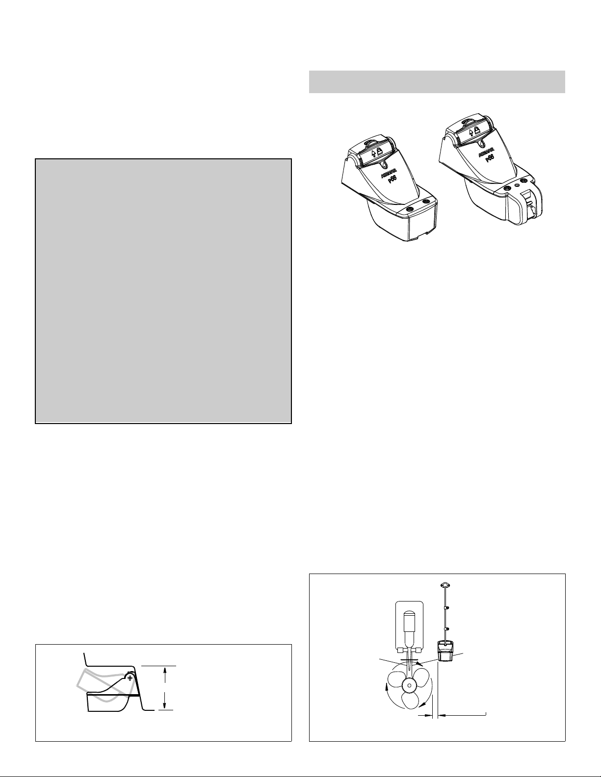
Multisensor
with Integral Release Bracket
Record the information found on the cable tag for future reference.
Part No._________________Date___________Frequency________kHz
TRIDUCER
multisensor
Transducer
Angle finder
Marine sealant (suitable for below waterline)
Screwdrivers
Straight edge
Pencil
Grommet(s) (some installations)
Cable ties
Water-based anti-fouling paint (mandatory in salt water)
Mounting Location
CAUTION: Do not mount in an area of turbulence or bubbles:
near water intake or discharge openings; behind strakes, struts,
fittings, or hull irregularities
CAUTION: Avoid mounting the sensor where the boat may be
supported during trailering, launching, hauling, or storage.
®
Applications
• Not recommended for boats with large inboard engine(s)
• Not recommended for stepped hull
• Good operation up to 44kn (50MPH)
• Vertically orients sound beam on hull with deadrise angle up to 30°
• Adjusts to transom angles from 2
• Bracket protects sensor from frontal impact only
°–22°
Tools & Materials
Safety goggles
Dust mask
Scissors
Masking tape
Electric drill
Drill bits:
Bracket holes 4mm, #23, or 9/64"
Transom hole (optional) 21mm or 13/16"
Cable clamp holes 3mm or 1/8"
min.: 127mm (5")
headroom
max. no speed sensor:
191mm (7-1/2")
max. with speed sensor:
213mm (8-1/2")
• For the best performance, the sensor must be in contact with smooth
water. To identify an area of clean water, observe the water flow off the
transom while the boat is underway.
• Allow headroom space above the bracket for it to release and rotate the
sensor upward (see Figure 1).
• Mount the sensor as close to the centerline (keel) of the boat as
possible to ensure the sensor remains in the water when the boat is
turning.
• Single drive boat—Mount at least 75mm (3") beyond the swing
radius of the propeller (see Figure 2). The starboard side where the
propeller blades are moving downward is preferred.
• Twin drive boat—Mount the sensor between the drives.
NOTE: Starboard
side of hull where
propeller blades are
moving downward is
preferred.
75 mm (3")
minimum beyond
swing radius
Figure 1. Headroom required on a stepped transom
Copyright © 2003 Airmar Technology Cor p.
Figure 2. Mounting location on single drive boat
Copyright © 2003 Airmar Technolog y Corp.
Page 2
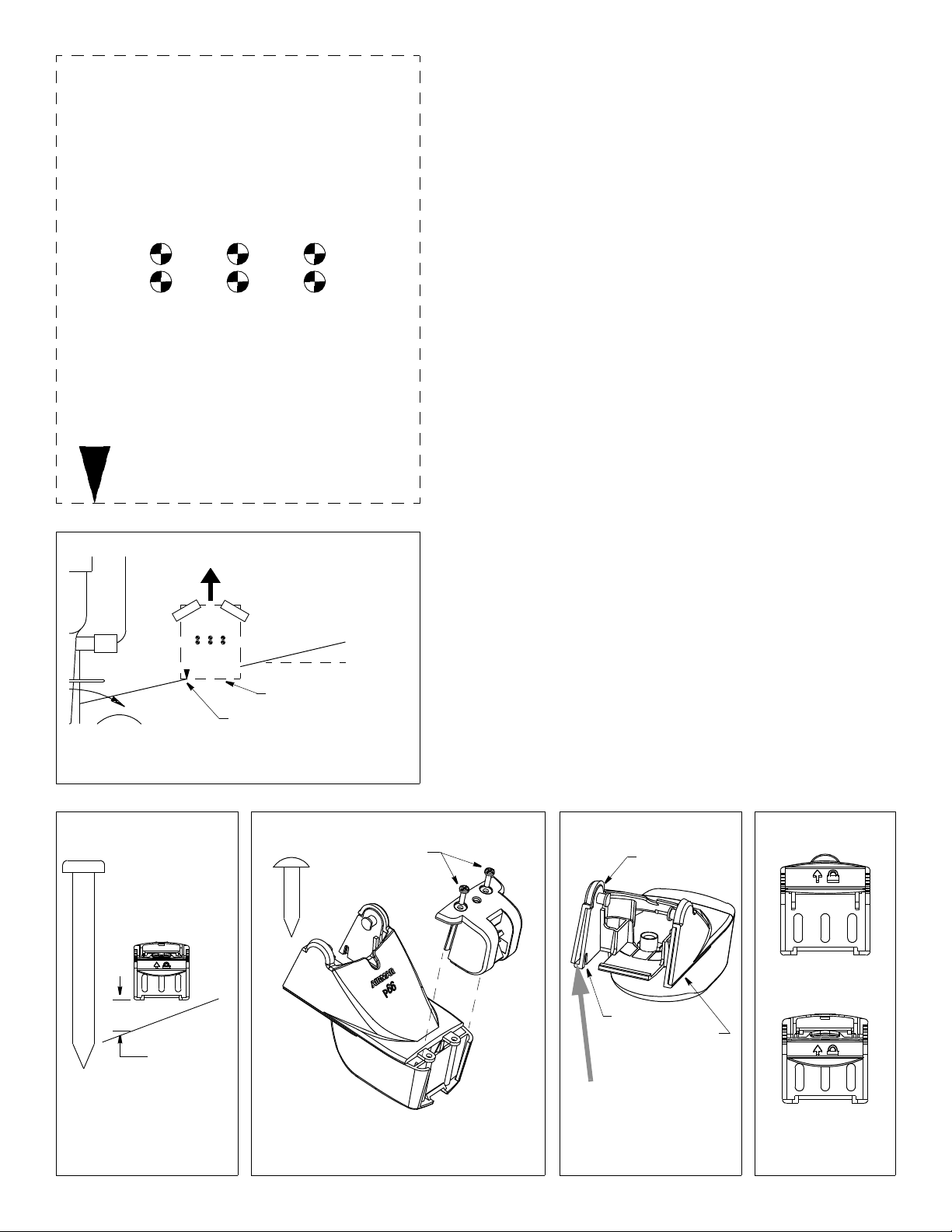
Figure 3. Template
for starboard side of boat
Pretest Speed & Temperature Functions
Connect the multisensor to the instrument and spin the paddlewheel. Check for a
speed reading and the approximate air temperature. If there is no reading(s) or it
is inaccurate, check the connections and repeat the test. If there is still no
reading(s) or it is inaccurate, return the product to your place of purchase.
Drill at locations labeled “B”
for transom angles 16° through 22°
(most small aluminum boats)
B
A
B
B
A
A
B
A
Drill at locations labeled “A”
for transom angles 2° through 15°
(most boats)
Align arrow with bottom of transom
parallel to waterline
Align template vertically
slope of hull
waterline
parallel to waterline
align template arrow with
bottom edge of transom
Figure 4. Template position
Copyright © 2003 Airmar Technolog y Corp.
Installation
CAUTION: Install the bracket before attaching the sensor.
Hole Drilling
CAUTION: To prevent drilling too deeply, wrap masking tape around the
bit 22mm (7/8") from the point.
Fiberglass hull—Minimize surface cracking by running the drill in
reverse until the gelcoat is penetrated.
1. Cut out the template (see Figure 3).
2. At the selected location on the starboard side of the hull, position the template,
so the arrow at the bottom is aligned with the bottom edge of the transom (see
Figure 4). Being sure the template is parallel to the waterline, tape it in place.
3. Using a 4mm, #23, or 9/64" bit, drill three holes 22mm (7/8") deep at the
locations indicated.
Compensating for the Transom Angle—Shim
CAUTION: For boats capable of speeds above 20kn (28 MPH)—The
trailing edge of the sensor must be deeper in the water than the leading
edge. This will ensure that the paddlewheel is in contact with the water at
high speeds.
For the best performance, the transducer beam must be aimed straight at the
bottom. Since the transom of most boats is angled, the bracket must compensate
for it. Measure the transom angle of the boat with an angle finder.
• Standard transom (13° transom angle)—The bracket is designed for a
standard 13° transom angle. The shim is NOT needed for this installation. Go to
"Mounting the Bracket."
• Stepped transom and jet boats (3° transom angle) —Use the shim with the
taper down.
• Small aluminum and fiberglass boats (20° transom angle)—Use the shim
with the taper up.
• If you are unsure about using the shim—Experiment with the shim. Follow
the instructions: “Mounting the Bracket”, “Attaching the Senor to the Bracket”,
and “Checking the Angle and Projection.”
bracket
screw
actual size
slope
of hull
38mm (1-1/2")
Figure 5. Distance between
corner of bracket and
bottom of transom
Copyright © 2003 Airmar Technol ogy Corp.
2
self-tapping
screw
actual size
cover
screws
(self-tapping
#6 x 5/8")
transducer
housing
Figure 6. Speed sensor or blank
(some installations)
Copyright © 2003 Airmar Technol ogy Corp.
speed
sensor
mounting ears
r
e
v
o
c
s
u
o
h
tab in slot
cover
flush with
housing
insert screwdriver here to
remove cover
Figure 7. Cover
(some installations)
Copyright © 2003 Airmar Technology Corp.
closed
g
n
i
opened
Figure 8. Bracket
retaining cover
Copyright © 2003 Airmar Technolog y
Page 3
Mounting the Bracket
1. Apply marine sealant to the threads of the three, #10 x 1-3/4", selftapping screws to prevent water seepage into the transom (see Figure
5). Screw the bracket (and shim if needed) to the hull. Do not tighten the
screws.
2. Using the vertical adjustment space on the bracket slots, slide the
bracket up or down until the distance between the bottom left corner
and the bottom of the transom equals 38mm (1-1/2"). Tighten the
screws.
Stepped Transom Only
If there is insufficient headroom under the step for the sensor to fully
release, remove the cover before proceeding (see Figure 1, maximum
headroom). This is necessary to access the bracket screws at a later time.
1. Remove the two screws that hold the speed sensor onto the transducer
housing (see Figure 6).
2. The paddlewheel assembly is a loose slip fit. Carefully, slide the speed
sensor upward while keeping the paddlewheel assembly inside (see
Figure 13).
3. Insert a blade screwdriver between the cover and the transducer
housing (see Figure 7). Pry each side apart, in turn.
4. Lift the cover up and off.
Attaching the Sensor to the Bracket
CAUTION: The retaining cover must be closed and latched to
prevent the sensor from coming off the bracket when the boat is
underway.
AB
slot (2)
pivot
post (2)
close &
latch
retaining
cover
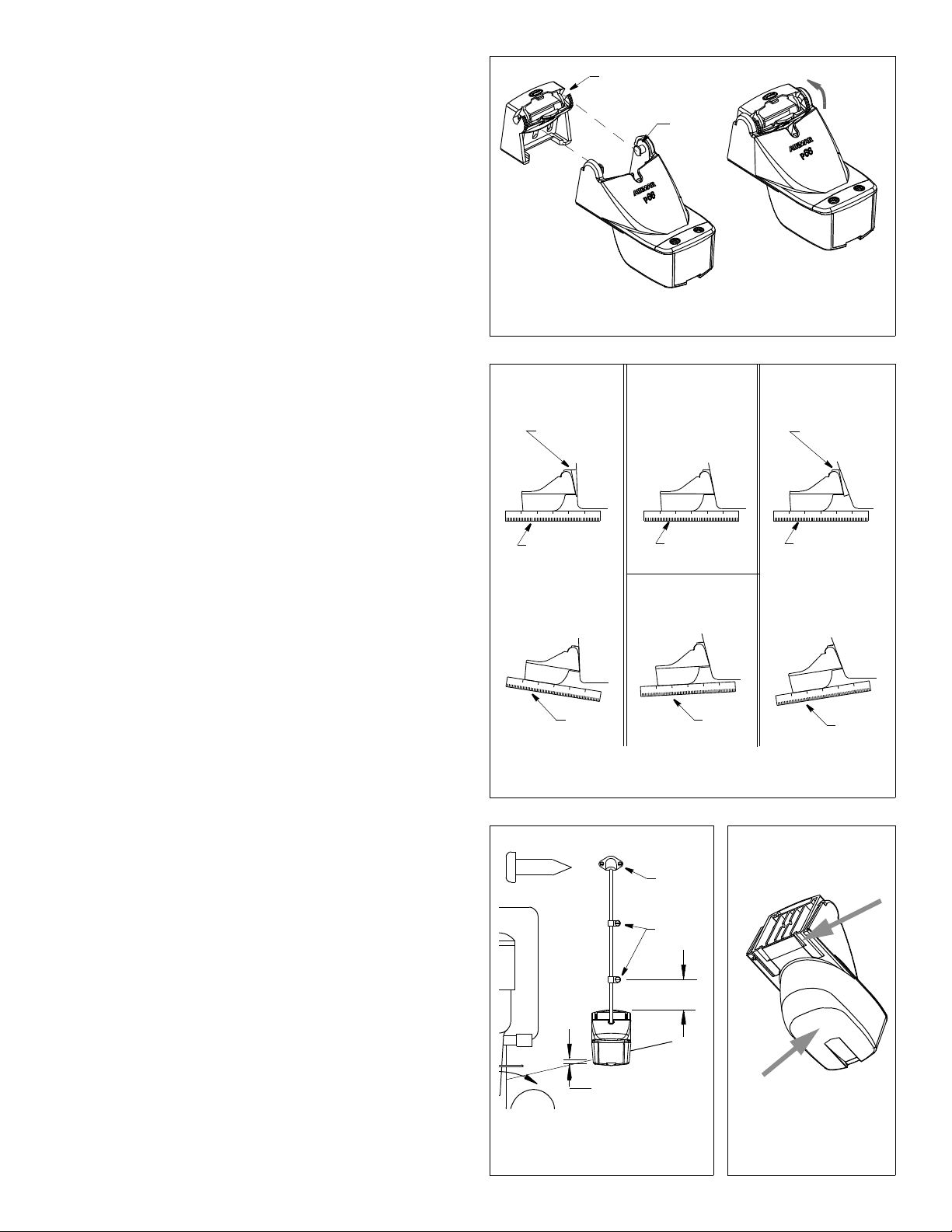
Figure 9. Attaching the sensor to the bracket
Copyright © 2003 Airmar Technology Cor p.
11° transom angle
shim with
taper down
YES YES
NO SHIM
YES
19° –22° transom angle2° –10° transom angle
shim with
taper up
1. If the retaining cover is closed, open it by depressing the latch and
rotating the cover downward (see Figure 8).
2. Insert the sensor’s pivot posts into the slots in the top of the bracket
(see Figure 9). Push down until the posts click into place.
3. Rotate the sensor downward until it snaps onto the bracket.
4. Close the retaining cover by rotating it upward until it latches.
Checking the Sensor Angle & Projection
CAUTION: Do not position the leading edge of the sensor lower
than the trailing edge because aeration will occur.
CAUTION: Do not position the sensor deeper into the water than
necessary to avoid increasing drag, spray, and water noise and
reducing boat speed.
1. Using a straight edge, sight the underside of the sensor relative to the
underside of the hull (see Figure 10). The stern of the sensor should be
1– 3 mm (1/16 –1/8") below the bow of the sensor or parallel to the
bottom of the hull.
2. Check that the bottom left corner of the sensor projections 3 mm (1/8")
below the bottom of the hull (see Figure 11).
3. If the sensor needs adjustment, release it upward (see “Releasing the
Sensor” below). Adjust the bracket. Tighten the screws.
Releasing the Sensor
Do one of the following (see Figure 12):
• Using the palm of your hand, give a sharp upward blow to the underside
of the transducer housing. Do not hit the speed sensor.
• Insert a blade screwdriver between the transducer housing and the
bottom of the bracket (either side). Push up on the screwdriver while
lifting up on the sensor.
nearly parallel
cable screw
actual size
nearly parallel
12°–18° transom angle
NO SHIM
YES
angle
reversed
Figure 10. Sensor angle adjustment
Copyright © 2003 , 2010 Airmar Technol ogy Corp.
cable
cover
cable
clamps
slight
angle
nearly parallel
angle
too steep
insert
screwdriver
at bevel
(either side)
NONO
Attaching the Cover & Blank or Speed Sensor (some installations)
1. Spread the sides of the cover horizontally (see Figure 7).
2. Slide the cover up and over the mounting ears.
3. Push the cover down until it sits flush on the transducer.
4. Squeeze the sides of the cover until the tabs snap into the slots.
5. Insert the side rails of the speed sensor or blank into the channels on
the back of the transducer housing (see Figure 6). Slide it downward.
Fasten the speed sensor or blank in place with the two, #6 x 5/8", selftapping screws.
50mm
(2")
Hull projection
3mm (1/8")
Figure 11. Vertical adjustment
and cable routing
Copyright © 2003 Airmar Technolog y Corp.
give sharp
blow with
palm of hand
Figure 12. Releasing
the sensor
Copyright © 2003 Airmar Technology Corp.
3
Page 4
Testing on the Water
1. Become familiar with your echosounder’s performance at a speed of 4kn
(5MPH).
2. Gradually increase the boat speed and observe the gradual decline in
performance due to turbulent water flowing over the transducer’s active
surface.
3. If the decline in performance is sudden (not gradual), identify the boat
speed at which the onset occurred. Return the boat to this speed, then
gradually increase speed while making moderate turns in both
directions.
4. If the performance improves while turning to the side on which the
sensor is installed, the transducer’s position probably needs
adjustment. It is probably in aerated water.
To improve performance, try the following one at a time in the order
given.
a. Increase the sensor’s angle in the water. Review “Compensating for
the Transom Angle—Shim” and see Figure 10.
b. Move the sensor deeper into the water in increments of 3mm (1/8")
(see Figure 11).
c. Move the sensor closer to the centerline of the boat.
Fill unused screw holes with marine sealant.
NOTE: High-speed operation [above 35 kn (40MPH)] may require less
projection in the water to improve performance and reduce the chance
that water pressure will cause the bracket to release.
5. Calibration—To match the speed shown on the display to the actual
speed of the boat, you may need to calibrate the instrument. Refer to
your instrument owner’s manual.
Cable Routing & Connecting
CAUTION: Do not remove the connector to ease cable routing. If
the cable must be cut and spliced, use Airmar’s splash-proof
Junction Box No. 33-035 and follow the instructions provided.
Removing the waterproof connector or cutting the cable, except
when using a water-tight junction box, will void the sensor warranty.
Route the sensor cable over the transom, through a drain hole, or through
a new hole drilled in the transom above the waterline.
1. If a hole must be drilled through the transom, choose a location well
above the waterline (see Figure 11). Check for obstructions such as
trim tabs, pumps, or wiring inside the hull. Mark the location with a pencil.
Drill a hole using the appropriate size bit to accommodate the connector.
2. Route the cable over or through the transom.
3. On the outside of the hull, secure the cable against the transom using
the cable clamps. Position one cable clamp 50mm (2") above the
bracket and mark the mounting hole with a pencil.
4. Position the second cable clamp halfway between the first clamp and
the cable hole. Mark this mounting hole.
5. If a hole has been drilled in the transom, open the appropriate slot in the
cable cover. Position the cover over the cable where it enters the hull.
Mark the two mounting holes.
6. At each of the marked locations, use a 3 mm or 1/8" bit to drill a hole
10mm (3/8") deep.
7. Apply marine sealant to the threads of the #6 x 1/2" self-tapping screws
to prevent water from seeping into the transom. If you have drilled a
hole through the transom, apply marine sealant to the space around the
cable where it passes through the transom.
8. Position the two cable clamps and fasten them in place. If used, push
the cable cover over the cable and screw it in place.
9. Route the cable to the instrument being careful not to tear the cable jacket
when passing it through the bulkhead(s) and other parts of the boat. Use
grommets where appropriate. To reduce electrical interference, separate
the sensor cable from other electrical wiring and the engine(s). Coil any
excess cable and secure it in place with cable ties to prevent damage.
10.Refer to your echosounder owner’s manual to connect the sensor to
the instrument.
4
Copyright © 2000 - 2010 Airmar Technology Corp. All rights reserved.
speed
sensor
housing
side view
shaft
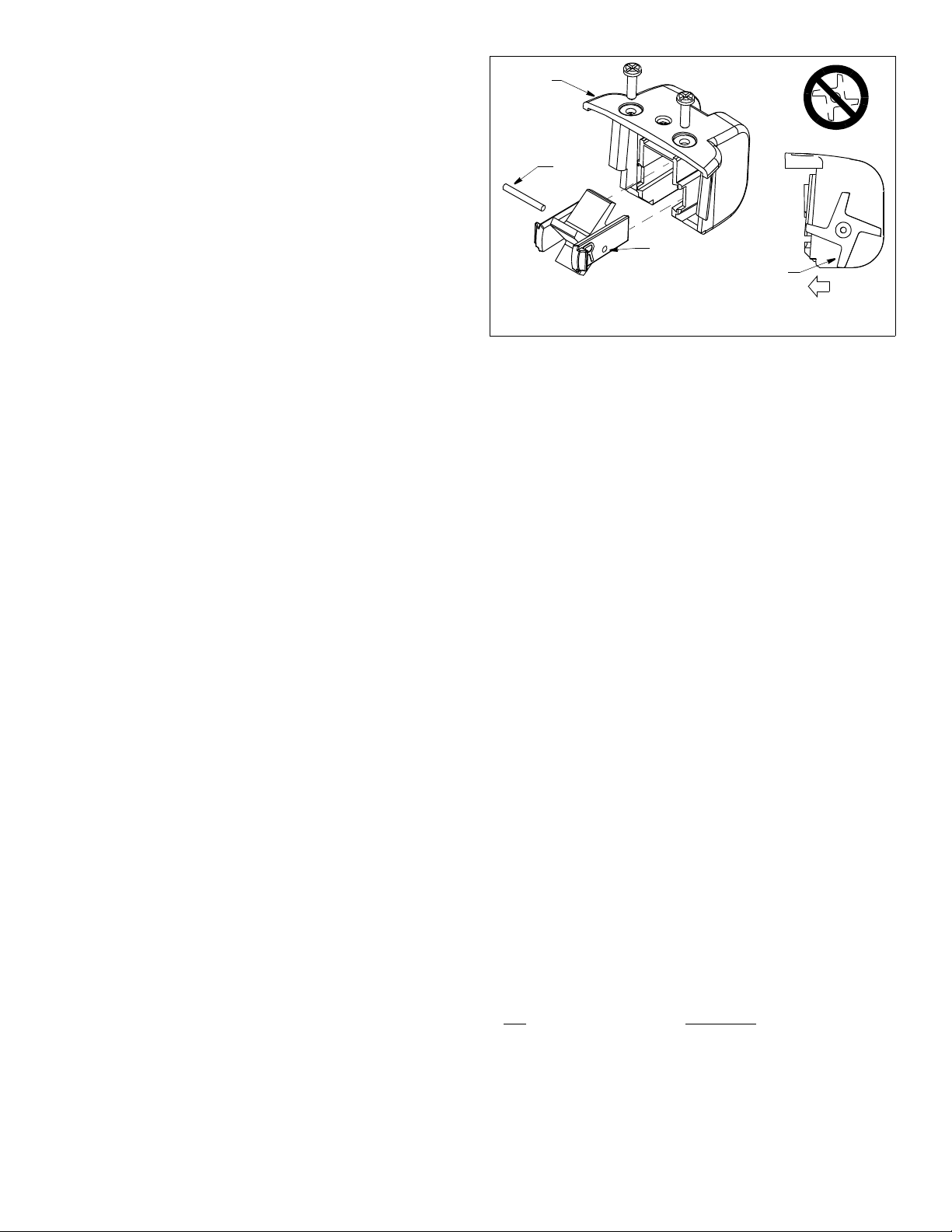
B
Figure 13. Servicing the speed sensor
insert shaft
through
hole B in
retaining
bar (2)
Copyright © 2003 Airmar Technolog y Corp.
short side
of blade
BOW
Checking for Leaks
When the boat is placed in the water, immediately check for leaks around
the screws and any holes drilled in the hull. Note that very small leaks may
not be readily observed. Do not leave the boat in the water unchecked for
more than three hours.
Anti-fouling Paint
Aquatic growth can accumulate rapidly on the sensor’s surface reducing
performance within weeks. Surfaces exposed to salt water that do not
interlock, must be coated with anti-fouling paint. Use water-based antifouling paint only. Never use ketone based paint, since ketones can attack
many types of plastic possibly causing damage to the transducer. Apply
paint every 6 months or at the beginning of each boating season.
Maintenance, Repair & Parts
Cleaning
Clean the transducer’s surface with a Scotch-Brite® scour pad and mild
household detergent taking care to avoid making scratches. If the fouling
is severe, lightly wet sand with fine grade wet/dry paper.
Servicing the Speed Sensor
If the paddlewheel becomes fouled or inoperable, remove it for cleaning.
Remove the two screws from the speed sensor (see Figure 13). Slide it
upward to remove it from the transducer housing. Grasp the two retaining
bars and pull to access the shaft.
After cleaning, slide the paddlewheel onto the shaft. Orient the short side
of the paddlewheel blade as shown on the side view. It must be oriented
correctly to measure the boat’s speed. Fit the shaft into the holes marked
“B” in the retaining bars. Note: There is a left retaining bar marked with an
L and a right retaining bar marked with an R. Slide the assembly into the
speed sensor housing. Note: The interior of the housing is marked with a
corresponding L and R. Re-attach the speed sensor.
Sensor Replacement & Parts
The information needed to order a replacement sensor is printed on the
cable tag. Do not remove this tag. When ordering, specify the part
number, date, and frequency in kHz. For convenient reference, record this
information on the top of page one.
Replace broken or worn parts immediately. The water-lubricated
paddlewheel bearings have a life of up to 5 years on low-speed boats
[less than 10kn (11MPH)] and 2 years on high-speed vessels. Some
depth/temperature units can be upgraded by adding a speed sensor.
Part
Paddlewheel Kit 33-473-01
Bracket and Wedge Kit 33-479-01
Speed Sensor Kit 33-346-03
Obtain parts from your instrument manufacturer or marine dealer.
Gemeco Tel: 803-693-0777
(USA) Fax: 803-693-0477
Airmar EMEA Tel: +33.(0)2.23.52.06.48
(Europe, Middle East, Africa) Fax: +33.(0)2.23.52.06.49
Part Number
email: sales@gemeco.com
email: sales@airmar-emea.com
 Loading...