

Page 1
or
or
or
or
INSTALLATION INSTRUCTION SUPPLEMENT
IMPORTANT
Use these instructions along with your sensor installation instructions.
These instructions supersede all other instructions where they differ.
17-276-01 rev. 02 7/01
WARNING
Installation of the anti-rotation bolt is mandatory!
Failure to install the anti-rotation bolt ma y result in the fairing rotating while the
boat is underway. The effect ma y be violent movement and loss of steering. This
could result in serious injury or death to passengers and/or damage to the boat or
other property .
High Speed Fairing
For Sensor Models: B45, B46, B256, B260,
B744V, SS505, SS544V
Caution
electrolytic corrosion will occur.
Tools and Materials Needed
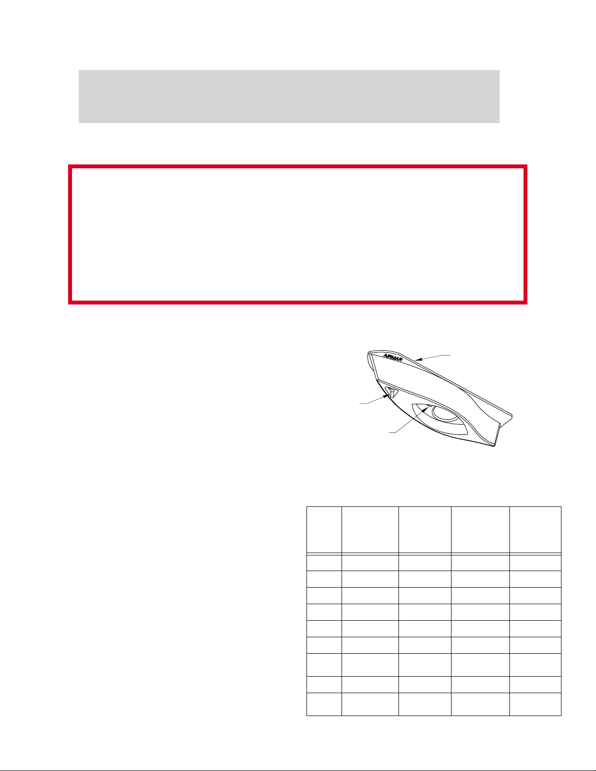
Identify Y our Model
The model # appears in the recess of the fairing (see Figure 1).
: Ne ver install a bronz e housing in a metal hull because
Digital level or bubble level & protractor
or
Band saw
hand saw
Safety goggles
Dust mask
Rasp
or
power tool
Electric drill
Drill bits, hole saw(s) (see Specifications Table 1)
or
Pilot hole 3mm
1/8"
Sandpaper
File (installation in metal hull)
Mild household detergent
or
weak solvent (alcohol)
Marine sealant (3M # 5200)
Slip-joint pliers
Mallet
For installation in a cored fiberglass hull, additional tools and
materials are needed (see page 4).
cutting
guide
triangular
recess for
anti-rotation bolt
model
number
Figure 1. High-Speed Fairing—B744V Shown
Specifications T able 1
Max. Hull
Sensor
Model
B45 50mm (2") 35mm (1-3/8") 22mm or 7/8" 10mm or 3/8"
B46 40mm (1-5/8") 35mm (1-3/8") 22mm
B256 45mm (1-3/4") 38mm (1-1/2") 30mm
B260 45mm (1-3/4") 74mm (2-7/8") 33mm
B744V 19mm (3/4") 32mm (1-1/4") 51mm
SS505 56mm (2-1/4") 32mm (1-1/4") 22mm
SS505
in metal hull
SS544V 19mm (3/4") 32mm (1-1/4") 51mm
SS544V
in metal hull
Thickness
(measured
perpendicular
to water surface)
56mm (2-1/4") 32mm (1-1/4") 25mm or 1" 10mm or 3/8"
19mm (3/4") 32mm (1-1/4") 54mm or 2-1/8" 10mm or 3/8"
Min. Fairing
Thickness
Drill Bit for
Sensor
or
7/8" 10mm or 3/8"
or
1-3/16" 13mm or 1/2"
1-5/16" 13mm or 1/2"
2" 10mm or 3/8"
7/8" 10mm or 3/8"
2" 10mm or 3/8"
The min. hull thickness for all sensor models is 6mm (1/4").
Drill Bit for
Anti-rotation
Bolt
Page 2
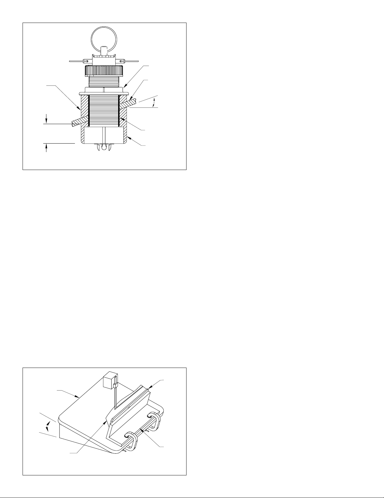
aft view
hull nut
backing
block
min. fairing
thickness
hull
slope of hull
deadrise
angle
parallel to
water surface
isolation
sleeve
fairing
Figure 2. SS544V with isolation sleeve
Cutting the Fairing
1.Measure the deadrise angle of the hull at the selected mounting
location using a digital level, or b ubble level and protractor (see
Figure 2).
2.Tilt the band saw table to the measured angle and secure the
cutting fence (see Figure 3).
Note : Be sure to orient the fairing on the band saw so the angle
cut matches the intended side of the hull and not the mirror
image.
3.Place the fairing on the table so the cutting guide rests against
the fence. The end with the triangular recess will be pointing
toward you for installation on the port side of the boat or
pointing away from you for installation on the starboard side.
Note : The end of the fairing with the triangular recess always
points forward toward the bow when installed.
4.There is a minimum thickness for the fairing at its thinnest
dimension (see Figure 2 and Specifications Table 1).
Warning : Always wear safety goggles and a dust mask.
5.Recheck steps 1 through 4; then cut the fairing.
6.Shape the fairing to the hull as precisely as possible with a rasp
or power tool.
7.Use the remaining section of the fairing as the backing block.
cutting
guide
band saw
table
Installation
Cored Fiberglass Hull —Follow separate instructions on page 4.
Caution : Never use solvents. Cleaners, fuel, paint, sealants, and
other products may contain strong solvent, such as acetone,
which attack plastics greatly reducing their strength.
Notice : Never pull, carry, or hold the sensor by the cable as this
may sever internal connections.
Drilling a Hole for the Sensor
Warning : Always wear safety goggles and a dust mask.
1.Drill a 3mm or 1/8" pilot hole perpendicular to the waterline from
inside the hull (see Figure 2). If there is a rib, strut or other hull
irregularity near the selected mounting location, drill from the
outside. (If the pilot hole is drilled in the wrong location, drill a
second hole in a better location. Apply masking tape to the
outside of the hull over the incorrect hole and fill it with epoxy.)
2.Using the appropriate size drill bit or hole saw, cut a hole from
outside the hull (see Specification Table 1).
3.Sand and clean the area around the hole, inside and outside, to
ensure that the sealant will adhere properly to the hull. If there
is any petroleum residue inside the hull, remove it with either
mild household detergent or a weak solvent (alcohol) before
sanding.
Metal hull —Remove all burrs with a file and sandpaper.
Drilling a Hole for the Anti-rotation Bolt
Dry fit the sensor to locate the hole for the anti-rotation bolt.
1.
B45, B46, B256, B260, SS505 —Remove the hull nut from the
sensor (see Figure 2).
2.Thread the sensor cable through the large hole in the fairing
and through the mounting hole in the hull. Seat the sensor
firmly in the recess in the fairing (see Figure 4).
Note : The sensor must be flush with the fairing. If it is recessed
more than 0.5mm (1/64") inside the fairing, you may carefully
file or sand the fairing flush with the sensor.
Warning : Always wear safety goggles and a dust mask.
3.Attach the appropriate size drill bit to your drill (see
Specifications Table 1). Slide the sensor’s stem with the fairing
in place into the mounting hole. (
the fairing is pointing forward to ward the bow
assembly in place and using the bolt hole in the fairing as your
guide, drill a hole through the hull for the anti-rotation bolt.
4.Remove the assembly and cable from the mounting hole.
5.Sand and clean the area around the hole, inside and outside, to
ensure that the sealant will adhere properly to the hull. If there
is any petroleum residue inside the hull, remove it with either
mild household detergent or a weak solvent (alcohol) before
sanding.
Metal hull —Remove any burrs around both holes with a file
and sandpaper.
Be sure the triangular recess in
.) While holding the
deadrise
2
angle
bow end
for installation
on port side
Figure 3. Cutting the fairing
cutting
fence
Bedding the Sensor
1.Remove the sensor from the fairing.
2.
Stainless steel sensor in metal hull only —Slide the
appropriate size isolation sleeve over the cable and onto the
stem of the sensor as far down as possible (see Figure 2).
sure
the top of the isolation sleeve will be below the top of the
backing block to prevent the sleeving from interfering with
tightening the hull nut.
Caution : To prevent electrolytic corrosion, never allow direct
contact between a stainless steel sensor and a metal hull!
Be
Page 3

WARNING
Installation of the anti-rotation bolt is mandatory!
Failure to install the anti-rotation bolt ma y result in the fairing rotating while the boat is
underway. The effect ma y be violent movement and loss of steering. This could result
in serious injury or death to passengers and/or damage to the boat or other property .
3.Apply a 2mm (1/16") thick layer of marine sealant to the sides of
the sensor that will contact the fairing and up the stem
6mm (1/4") higher than the combined thickness of the fairing,
hull, backing block, and hull nut. This will ensure there is marine
sealant in the threads to seal the hull and hold the hull nut
securely in place (see Figure 4).
Stainless steel sensor in metal hull —Apply the marine
sealant to the outside of the sleeving instead of the stem itself.
4.Thread the sensor cable through the fairing and seat the sensor
firmly within the recess in the fairing.
5.Apply a 2mm (1/16") thick layer of marine sealant to the surface
of the fairing that will contact the hull.
Bedding the Anti-rotation Bolt and Installing
1.From outside the hull, thread the cable through the mounting
hole. Push the stem of the sensor (with the fairing in place) into
the mounting hole using a twisting motion to squeeze out excess
sealant (see Figure 4).
Caution : Never strike the sensor.
2.From inside the hull, slide the backing block onto the sensor
cable and stem seating the backing bloc k firmly against the hull.
Screw the hull nut in place and tighten it with slip-joint pliers.
Wood hull —Allow for the wood to swell.
Fiberglass hull — Do not over-tighten and crush the hull.
Stainless steel sensor in metal hull — Be sure the top of the
isolation sleeve is below the top of the backing block to prevent
the sleeving from interfering with tightening the hull nut.
3.Apply a 2mm (1/16") thick layer of marine sealant to the antirotation bolt, 6mm (1/4") higher than the combined thickness of
the fairing, hull, backing bloc k, washer, and nut. This will ensure
that there is marine sealant on the threads to seal the hull and
hold the nut securely in place (see Figure 4).
4.Apply a 2mm (1/16") thick layer of marine sealant to one side of
the nut.
5.Push the bolt through the fairing and into the hull.
6.From inside the hull, slide the w asher onto the bolt. Slide the nut
onto the bolt with the
Screw the nut in place and tighten it with slip-joint pliers.
Wood hull —Allow for the wood to swell.
Fiberglass hull — Do not over-tighten and crush the hull.
7.Apply marine sealant to the
Push the plug into the triangular recess in the fairing.
triangular plug fits one way only. Be sure
plug is exposed, matching the curve on the outside of the
fairing. Tap it into place with a mallet.
Note : For smooth water flow over the transducer, be sure that
the external surface of the installed triangular plug is FLUSH
with the external curved surface of the fairing.
8.Proceed with the installation instructions that came with your
sensor beginning with “Installing” step #4.
sealant side facing the backing block .
FLAT side of the triangular plug.
The
the curved side of the
marine
sealant
detail
⇐
BOW
anti-rotation
hull
Figure 4. Bedding and installing the anti-rotation bolt—B744V shown
bolt
nut &
washer
triangular plug
with curved
surface facing
outward
marine sealant
hull nut
backing
block
fairing
3
Page 4

or
or
or
or
or
or
Installation in a Cored Fiberglass Hull
The core (wood or foam) must be cut and sealed carefully. The core
must be protected from water seepage, and the hull must be
reinforced to prevent it from crushing under the hull nut allowing the
sensor to become loose.
Additional Tools and Materials Needed
Drill bit(s), hole saw(s) (see Specifications Table 2)
Cylinder
Wax
Tape
Casting epoxy
Preparing a Cored Fiberglass Hull
Warning : Always wear safety goggles and a dust mask.
1.Drill a 3mm or 1/8" pilot hole from inside the hull (see Figure 5). If
there is a rib, strut, or other hull irregularity near the selected
mounting location, drill from the outside. If the hole is drilled in the
wrong location, drill a second hole in a better location. Apply
masking tape to the outside of the hull over the incorrect hole and
fill it with epoxy.
2.Using the appropriate size drill bit or hole saw cut a hole from
outside the hull through the
Table 2).
Be sure to hold the drill plumb, so the hole will be
perpendicular to the water surface.
Specifications T able 2
Model
B45 22mm or 7/8" 35mm or 1-3/8" 10mm or 3/8" 19mm or 3/4"
B46 22mm
B256 30mm
B260 33mm
B744V 51mm
SS505 22mm
SS544V 51mm
Drill Bit for
Sensor
(outer skin)
7/8" 35mm or 1-3/8" 10mm or 3/8" 19mm or 3/4"
1-3/16" 40mm or 1-5/8" 13mm or 1/2" 25mm or 1"
1-5/16" 44mm or 1-3/4" 13mm or 1/2" 25mm or 1"
2" 60mm or 2-3/8" 10mm or 3/8" 19mm or 3/4"
7/8" 35mm or 1-3/8" 10mm or 3/8" 19mm or 3/4"
2" 60mm or 2-3/8" 10mm or 3/8" 19mm or 3/4"
outer skin only (see Specification
Min. Size
Drill Bit for
Sensor
(inner cored
hull)
Drill Bit for
Anti-rotation
Bolt
(outer skin)
Anti-rotation Bolt
(inner cored hull)
Min. Size
Drill Bit for
Dimension equal to
pour in
casting
epoxy
hull
the thickness of the
hull’s outer skin to
ensure adequate
clearance
solid or hollow
cylinder
inner skin
core
outer skin
Figure 5. Preparing a cored fiberglass hull
3.Using the appropriate size drill bit or hole saw cut through the
inner skin and most of the core from inside the hull keeping
the drill perpendicular to the hull (see Specification Table 2).
The core material can be very soft. Apply only light pressure
to the hole saw after cutting through the inner skin to avoid
accidentally cutting the outer skin.
Caution : The optimal interior hole diameter is affected by the
hull’s thickness and deadrise angle. It must be large enough
in diameter to allow the core to be completely sealed.
4.Remove the plug of core material, so the inside of the outer
skin and the inner core of the hull is fully exposed. Sand and
clean the inner skin, core, and the outer skin around the hole.
5.Coat a hollow or solid cylinder of the correct diameter with
wax and tape it in place. Fill the gap between the cylinder and
hull with casting epoxy. After the epoxy has set, remove the
cylinder.
Caution : Always completely seal the hull to prevent water
seepage into the core.
6.Sand and clean the area around the hole, inside and outside,
to ensure that the sealant will adhere properly to the hull. If
there is any petroleum residue inside the hull, remove it with
either mild household detergent or a weak solvent, such as
alcohol, before sanding.
7.Follow the same procedure to prepare the hull for the antirotation bolt (“Preparing a Cored Fiberglass Hull”, steps 2
through 6).
8.Proceed with the installation beginning with "Bedding the
Sensor" on page 2.
AIRMAR
TECHNOLOGY CORPORATION
35 Meadowbrook Drive, Milford, New Hampshire 03055-4613, USA
■
www.airmar.com
4
 Loading...