

Page 1
50W Solar Panel Battery Maintainer
Mainteneur de batterie pour panneau solaire de 50W
Mantenedor de carga de batería para panel solar de 50W
Instruction Manual
Model/Modèle/Modelo:
Manuel d’instructions
FSFP50MAT-BL
Manual de instrucciones
50W Rigid Solar Panel / Panneau solaire rigide de 50W
Panel solar rígido de 50W
PWM SOLAR CHARGE
CONTROLLER GEN 2.0
Model: C-FSFP50MAT-A03
x 4
System Voltage: 12V
CAUTION: The default setting is for use with
sealed lead-acid batteries. For a dierent
battery type, please refer to the instruction
manual or visit www.furrion.com.
Z-Bracket Mount Kit
Ensemble d'installation
Rooftop Box
Boîte de toit
Caja de techo
pour support en Z
Kit de montaje para
soporte en forma de Z
PWM Controller
Régulateur MLI
Controlador PWM
Mode Key
* Picture shown for reference only
Photo présentée à titre de référence seulement
La imagen que se muestra es únicamente de referencia
Page 2

Thank you for purchasing this Furrion® product. Before operating or installing, please read these
instructions carefully. This instruction manual contains information for safe use, installation, and
maintenance of the product.
Please keep this instruction manual in a safe place for future reference. Be sure to pass on this
manual to new owners of this product.
The manufacturer does not accept responsibility for any damages due to not observing these
instructions.
English
Supplier’s Declaration of Conformity
47 CFR § 2.1077 Compliance Information
Unique Identifier:
Trade Name: Furrion
Model Number: C-FSFP50MAT-A03
Responsible Part--U.S. Contact Information
Furrion Innovation Center & Institute of Technology
52567 Independence Ct., Elkhart, IN 46514, USA
Toll free:1-888-354-5792;
Email: support@furrion.com
FCC Compliance Statement(for products subject to Part 15):
This device complies with Part 15 of the FCC Rules. Operation is subject to the
following two conditions: (1) This device may not cause harmful interference, and (2)
this device must accept any interference received, including interference that may
cause undesired operation.
1
Page 3
Table of Contents
Table of Contents ....................................................................................................... 2
Explanation of Symbols ............................................................................................ 3
General ........................................................................................................................ 3
Safety Precautions for Installing a Photovoltaic System ....................................................4
Safety Precautions When Working with Batteries ................................................................4
General Installation Notes ................................................................................................................ 5
Product Overview ...................................................................................................... 5
50W Rigid Solar Panel ........................................................................................................................5
Rooftop Box ............................................................................................................................................ 6
10A Pulse Width Modulation (PWM) Controller ......................................................................7
Z-Bracket Mount Kit ............................................................................................................................ 8
Before Using ............................................................................................................... 8
What’s in the Box ..................................................................................................................................8
Installation .................................................................................................................. 9
Secure Z-Brackets to Frame of the Solar Panel ..................................................................... 9
Install Solar Panel to Mounting Surface ..................................................................................... 10
Install Rooftop Box ...............................................................................................................................12
Install PWM Controller .......................................................................................................................13
Connection .................................................................................................................. 15
Wiring Diagram ......................................................................................................................................15
Installation on RV ..................................................................................................................................15
Operation..................................................................................................................... 16
Suggested Use ...................................................................................................................................... 16
PWM Controller Status Indicators ................................................................................................ 16
Mode Selection ..................................................................................................................................... 16
Charging Parameters.......................................................................................................................... 17
Troubleshooting ......................................................................................................... 17
Maintenance ............................................................................................................... 18
English
2
Page 4
Explanation of Symbols
This manual has safety information and instructions to help eliminate or reduce the risk of
accidents and injuries. Always respect the safety warnings identified by the following symbols.
The following safety phrases indicate the degree of risk of injury or property damage.
English
Indicates an imminently hazardous situation which, if not avoided, will result in death or
serious injury.
DANGER
WARNING
Indicates a potentially hazardous situation which, if not avoided, could result in death or
serious injury.
CAUTION
Indicates a potentially hazardous situation which, if not avoided, may result in minor or
moderate personal injury, or property damage.
General
Please carefully read the following installation and safety instructions. Non-compliance with
these instructions may void the product warranty.
This guide contains information regarding the installation and safe handling of Furrion solar panels
and components. All instructions must be read and understood before attempting installation. If
there are any questions, please contact your dealer or Furrion for further information.
The installer should conform to all safety precautions in the guide when installing solar panels.
Before installing a solar photovoltaic system, the installer should become familiar with the
mechanical and electrical requirements for photovoltaic systems. Keep this guide in a safe place
for future reference.
● The installation of solar photovoltaic (PV) systems requires specialized skills and knowledge.
The installer assumes all risk of injury, including risk of electric shock. Solar panels
installation should be performed only by qualified persons.
● All solar panels come with a permanently attached junction box. Your dealer can provide
additional extension cables to simplify module wiring.
● Exercise caution when wiring or handling solar panels exposed to sunlight.
● Do not connect or disconnect wires attached to solar panels when they are exposed to
sunlight, otherwise an electric arc may occur. Arcs can cause burns, fires, or other safety
problems. Always exercise caution when connecting and disconnecting wiring solar panels.
● Photovoltaic solar modules convert light energy to direct-current electrical energy and are
designed for outdoor use. Proper design of support structures is the responsibility of the
system designer and installer.
3
Page 5
● Do not attempt to disassemble the solar panel, and do not remove any attached nameplates
or components. Doing so will void the warranty.
● Do not apply paint or adhesive to the solar panel.
● Do not use mirrors or other hardware to artificially concentrate sunlight on the solar panel.
● When installing solar panels, observe all applicable local, regional, and national codes &
regulations. Obtain a building and/or electrical permit when required.
Work Safely
● Wear protective eye wear and appropriate clothing during installation. Use extreme caution
when working with electricity and when working around batteries. Use properly insulated
tools only.
● Use care when working on an RV roof, always use rated safety harnesses and ladders during
installation and maintenance.
Safety Precautions for Installing a Photovoltaic System
● Solar panels produce electrical energy when exposed to sunlight.
● Keep children well away from the system while transporting and installing mechanical and
electrical components.
● Completely cover all solar panels with an opaque material during installation to prevent
electricity from being generated.
● Do not wear metallic rings, watches, or other metallic devices while installing or
troubleshooting photovoltaic systems.
● Use appropriate safety equipment (insulated tools, insulating gloves, etc.) approved for use
on electrical installations.
● Observe the instructions and safety precautions for all other components used in the system,
including wiring and cables, connectors, DC-breakers, mounting hardware, inverters, etc.
● Use only equipment, connectors, wiring, and mounting hardware suitable for use in a
photovoltaic system.
● Always use the same type of solar panel within a particular photovoltaic system.
● Under normal operating conditions, solar panels will produce currents and voltages that may
vary with than those listed in the data sheet. Data sheet values are applicable at standard
test conditions only.
● Short-circuit current and open-circuit voltages should be multiplied by a factor of 1.25 when
determining the system voltage/ampacity rating for the fuses and charge controllers.
English
Safety Precautions When Working with Batteries
● Batteries contain very corrosive diluted sulfuric acid as electrolyte. Precautions should be
taken to prevent contact with skin, eyes, or clothing.
● Batteries generate hydrogen and oxygen during charging, which may form an explosive gas
mixture.
● Store batteries in a well ventilated area and follow the battery manufacturer’s
recommendations. Never smoke, allow a spark, or flame near the batteries.
● Never allow a foreign object to drop or rest on the battery. Doing so could lead to fire,
explosion, or harmful out-gassing.
4
Page 6
● Remove metal items such as rings, bracelets, and watches when working with batteries. The
(123mm)
batteries can produce a short circuit current high enough to weld a ring or similar object to
the metal, causing a severe burn.
● If you need to remove a battery, always remove the negative terminal from the battery first.
● Only use properly insulated tools when making battery connections.
General Installation Notes
English
● Drainage holes must not be covered by the mounting system. The solar panel should be
mounted with glass surface upwards.
● Do not lift the solar panel by grasping its junction box or electrical leads.
● Do not stand or step on the solar panel.
● Do not drop the solar panel or allow objects to fall on the solar panel.
● Do not place any heavy objects on the solar panel.
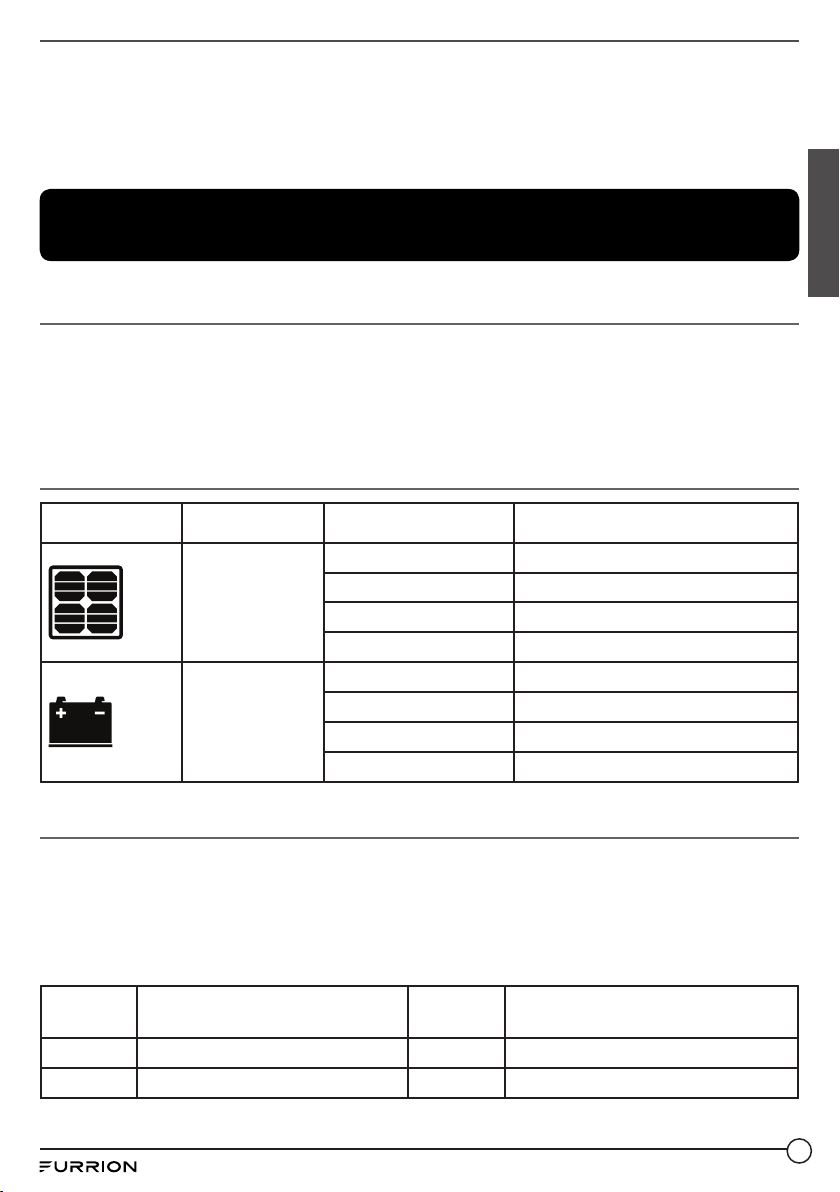
Product Overview
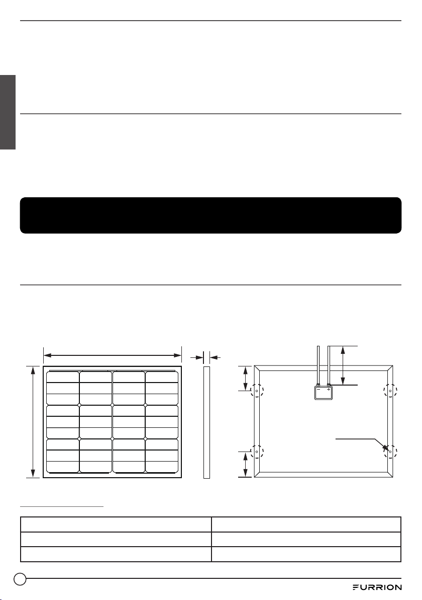
50W Rigid Solar Panel (C- FSFP50MAT-A01 /
C- FSFP50MAT-001)
Furrion solar panels are made of monocrystalline solar cells in series with high efficiency, high
transmission rate, low iron tempered glass, anti-aging EVA, high flame resistant TPT laminate,
and anodized aluminium alloy frames. They are designed for easy installation, extended
longevity, and resistance to damage incurred by high wind or hail.
26⁄” (670mm)
1⁄” (30mm)
35⁄” (900mm)
21⁄” (540mm)
Specifications
Maximum Power (Pmax) 50W
Max Power Voltage (Vmp) 18.5V
Max Power Current (Imp) 2.7A
5
4⁄”
(123mm)
4⁄”
4*⁄” (6mm)
Page 7
Open Circuit Voltage (Voc) 22.6V
Short Circuit Current 2.9A
Cell Efficiency 18%
Cell Type Monocrystalline
Maximum System Voltage 36V DC
Power Tolerance ± 5%
Series Fuse Rating 5A
Temperature Co-efficient (Power) -0.43%/ °C
Temperature Co-efficient (Voltage) -0.32%/°C
Temperature Co-efficient (Current) +0.02%/ °C
NOCT (Air 20°C, Sun 0.8kW/m², Wind 1m/s) 45±3°C
Weight 9.26lbs (4.2kg)
Cable 2.5mm2, PV1-F, 35⅜”(900mm)
Connector Stranded Lead
Frame Anodized Aluminum (Black)
Operation Temperature -40°F to 185°F (-40°C to 85°C)
IP Rating IP65
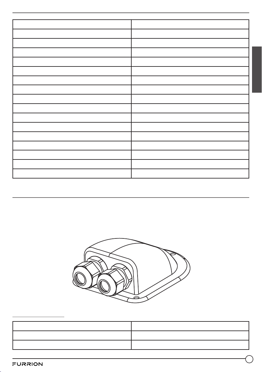
Rooftop Box (C-FSFP50MAT-A02 / C-FSFP50MAT-002)
● IP65 dust and water resistant.
● Designed to mount with adhesive sealant or standard #8 RV button head screws (not
included).
● Constructed with anti-UV agent to extend weather resistance and to limit color change
during long periods of exposure to the elements.
English
Specifications
Material Constructed with anti-UV agent
Dimension (W x H x D) 5⅛” x 1¾” x 3⅝” (130 x 43 x 93 mm)
IP Rating IP65
6
Page 8
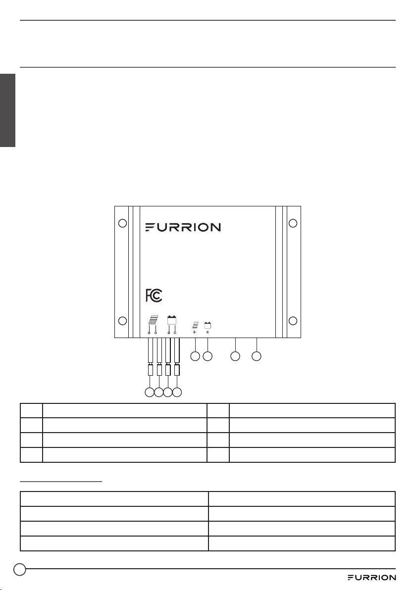
10A Pulse Width Modulation (PWM) Controller
(C-FSFP50MAT-A03 / C-FSFP50MAT-003)
● IP65 dust and water resistant.
● 12V system voltage.
● LED numeric display and mode selection button.
● Intelligent 3-stage PWM charging algorithm applies variable equalization, boost, and float
modes.
English
● Smart charging profile ensures that batteries are fully charged, balanced, and desulfurized
effectively extending the service life of the batteries.
● Charging program options are available for sealed, GEL, flooded lead acid, or lithium iron
phosphate batteries.
● Controller memory retains mode and battery type information, making operation easy and
convenient.
● Protection against overcharge and reverse polarity connection.
PWM SOLAR CHARGE
CONTROLLER GEN 2.0
Model: C-FSFP50MAT-A03
System Voltage: 12V
CAUTION: The default setting is for use with
sealed lead-acid batteries. For a dierent
battery type, please refer to the instruction
manual or visit w ww.furrion.com.
Mode Key
5 6 7 8
1 2 3 4
1 Positive solar input lead 5 Charge indicator
2 Negative solar input lead 6 Battery indicator
3 Positive battery output lead 7 Mode indicator
4 Negative battery output lead 8 Mode selection button
Specifications
Cable for Solar Panel Connection 14AWG, 23⅝" (600mm)
Cable for Battery Connection 14AWG, 23⅝" (600mm)
Connector Stranded Lead
Dimension (W x H x D) 3¼" x ⁄” x 2⁄” (82 x 20 x 58 mm)
7
Page 9
Operation Temperature -31°F to 149°F (-35°C to 65°C)
IP Rating IP65
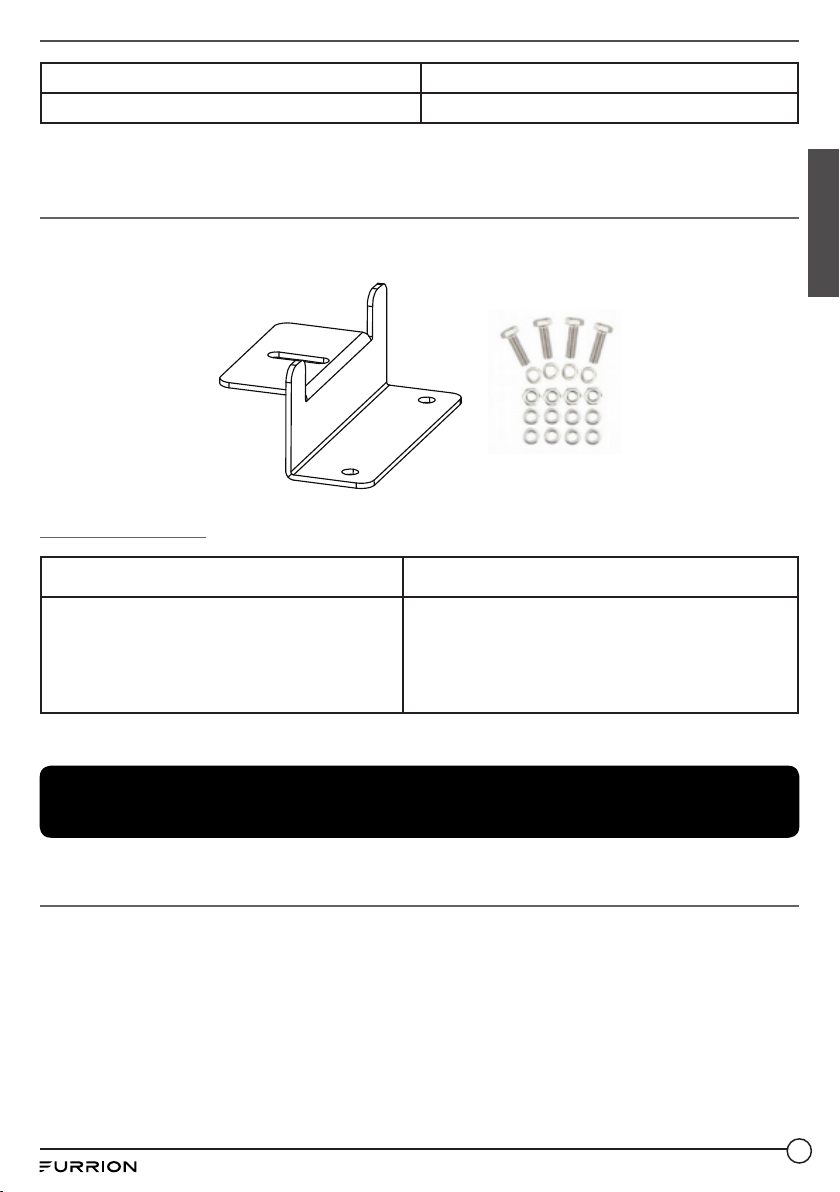
Z-Bracket Mount Kit (C-FSFP50MAT-A04 /
C-FSFP50MAT-004)
● Aluminum construction with stainless steel nuts, bolts, and washers.
● Maintenance free & easy installation.
x 4
Specifications
Dimension (per bracket) (W x H x D) 3⁄" x 1⅝" x 3⅞" (88 x 42 x 100 mm)
Aluminum Z-Bracket x4
M6 SS304 Hex Head Bolt x 20mm x4
Z-Bracket Mount Kit includes
NOTE: This kit does NOT include hardware to attach the Z-Brackets to roof.
M6 SS304 Nut x4
M6 SS304 Split Lock Washer x4
M6 SS304 Flat Washer x8
English
Before Using
What’s in the Box
Make sure you have all the following items included in the packaging. If any item is damaged or
missing, contact your dealer.
● 50W Rigid Solar Panel x 1
● Rooftop Box x 1
● PWM Controller x 1
● Z-Bracket Mount Kit x 1
● Quick Start Guide x 1
● Warranty Manual x 1
8
Page 10
Installation
M6 Nut
M6 Hex Bolt
M6 Split Lock
Washer
M6 Flat Washer
M6 Flat Washer
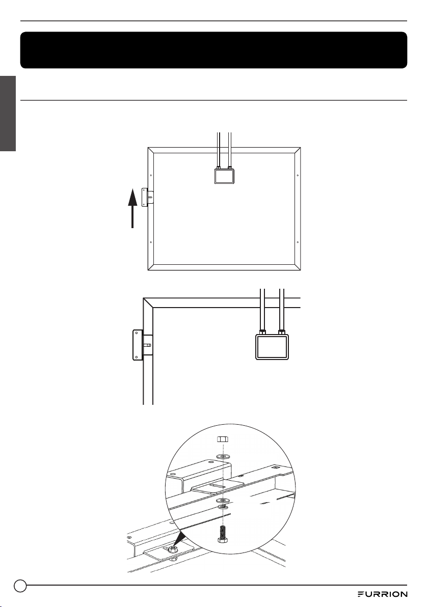
Secure Z-Brackets to Frame of the Solar Panel
1. Affix a Z-Bracket along the short side of the solar panel frame. Make sure that mounting foot
of the Z-Bracket is facing outward from the solar panel frame.
English
2. Align the mounting hole of the Z-Bracket with that of the solar panel frame.
-
+
-
+
3. Fix the Z-Bracket on the solar panel frame.
9
Page 11

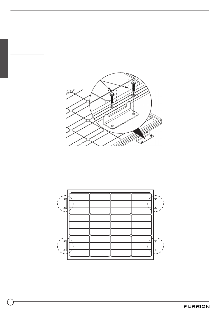
4. Repeat the steps above for each Z-Bracket.
-
+
Install Solar Panel to Mounting Surface
Selecting the Mounting Location
● Select a suitable location for the installation of the solar panel.
● Install the solar panel in a clear location on the roof of the RV that will receive maximum
exposure to the sun.
● Solar panels should be mounted as far away from rooftop obstructions (AC units, plumbing
vents, skylights, etc.) as possible.
● If solar panels must be installed near rooftop obstructions, try to orient the modules with
broadside facing the obstruction.
English
Selecting the Proper Mounting Structure and Hardware
● Observe all instructions and safety precautions included with the mounting system to be
used with the solar panel.
● Do not drill holes in the glass surface of the solar panel. Doing so will void the warranty.
● Do not drill additional mounting holes in the solar panel frame. Doing so will void the warranty.
● Solar panels must be securely attached to the mounting structure using four mounting points
for normal installation.
● The mounting structure and hardware must be made of durable, corrosion, and UV-resistant
materials.
● Select mounting location such that screw holes on the mounting brackets attached to the
solar panel frame are aligned with the structural framing of the roof.
Mounting Solar Panels
● In regions with heavy snowfall in winter, select the height of the mounting system so that the
lowest edge of the solar panel is not covered by snow for any extended period of time.
● Solar panels must be securely attached to the mounting structure.
● Provide adequate ventilation under the solar panel.
● Before installing solar panels on a roof, ensure that the roof construction is suitable. In
addition, any roof penetration required to mount the solar panel must be properly sealed to
prevent leaks.
10
Page 12
● Always keep the backsheet of the panel free from foreign objects or structural elements, which
(fasteners not
included, #10 screws
recommended)
could come into contact with the panel, especially when the panel is under mechanical load.
● Ensure panels are not subjected to wind or snow loads exceeding the maximum permissible
loads (176lbs/80kg), and are not subjected to excessive forces due to the thermal expansion
of the support structures.
Installation
1. Affix panels to roof by screwing appropriate mounting hardware through Z-Bracket holes
English
into roof. Install solar panel on a relatively flat surface on the roof.
NOTE:
● Ensure screw locations are backed by a solid structure such as a rafter, stud, etc.
● Apply self-leveling adhesive (not included) to the bottom of the Z-Brackets to create a
water tight seal.
2. Mount the solar panel such that at least 2 of the mounting feet have screws penetrating the
metal or wooden framing trusses.
3. Repeat for all fastener locations.
11
Page 13
4. Seal around edges of all Z-Brackets and screws where they come in contact with or
penetrate the mounting surface.
NOTE: Make sure that self-leveling silicon adhesive is applied evenly around all edges of
bracket and the mounting screws with no gaps.
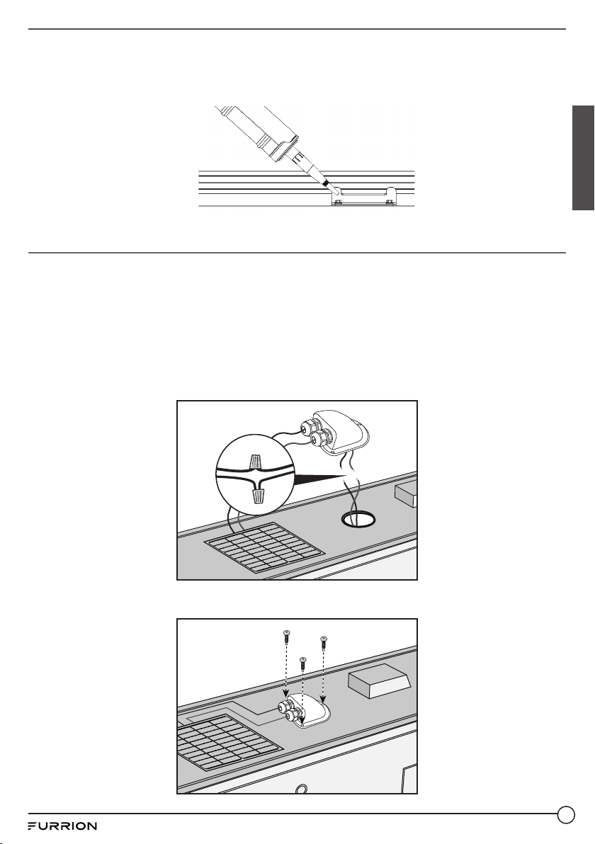
Install Rooftop Box
1. Drill a small pilot hole on the chosen location, if desired. Enlarge the pilot hole with a suitable
drill bit. The hole drilled must be large enough for cables to drop through.
2. File and remove any sharp edges around the hole that were created during drilling.
Thoroughly clean the mounting area to ensure proper sealant bonding.
3. Insert positive/negative PV wires from the solar panel junction box into the threaded strain
relief holes on the Rooftop Box.
4. Attach the positive/negative PV wires ("+" and "-" on the tape at the end) inside of the
Rooftop Box to the wires connected to the PWM controller using twist-on wire connectors/
Marrettes (not included).
English
5. Use standard #8 RV button head screws (not included) to fasten the Rooftop Box to the RV
roof by drilling through the 3 screw holes around the perimeter of the Rooftop Box base.
12
Page 14
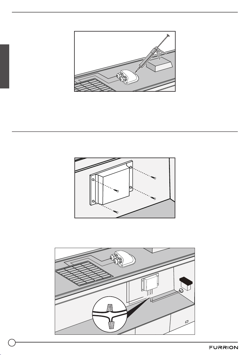
6. Use appropriate self-leveling silicon sealant as recommended by your RV dealer or
manufacturer to properly seal the perimeter of the Rooftop Box.
English
NOTE:
● Tighten the strain reliefs on the Rooftop Box.
● Apply self-leveling adhesive (not included) to the mounting hole.
Install PWM Controller
1. Mount the PWM controller on a flat surface inside of the RV with 4 screws (not included, #3
recommended).
2. Mount the PWM controller close to the battery inside the front compartment of the RV.
3. Attach the positive/negative battery wire leads on the PWM controller to the positive/negative
battery cables (not included) using twist-on wire connectors/Marrettes (not included).
4. Attach the positive/negative wires (not included) from the Rooftop Box to the to the positive/
negative solar leads on the PWM controller using twist-on wire connectors/Marrettes (not included).
13
Page 15
5. Ensure that an appropriate electrical connection is made with the battery by using twiston wire connectors/Marrettes (not included), and crimping ring connectors (or similar) for
connection to battery terminals.
6. Fasten and secure all loose wires according to the appropriate electrical code.
7. A 10A in-line fuse is recommend to be installed on the positive battery side within 7 inches of
the positive battery post.
NOTE:
● It is recommended to connect the PWM battery output leads to the battery first, then
connect the solar input leads to the solar panel wires.
● Do not short circuit the PWM battery output leads, doing so may damage the PWM controller
and/or battery.
PV/Battery Wire Size
Since the solar output current can vary due to array connection methods, sunlight, and
temperature, the minimum wire size must be in accordance with the maximum array short-circuit
current. The PWM input and output wires will have the same voltage and current. Therefore,
the wire gauge from the solar panel to the PWM and from the PWM to the battery should be the
same. Please refer to the following wire gauge chart for reference:
English
Wire Length with 10%
Voltage Drop
0 to 20 ft 0 to 6 ft 16 AWG 16 AWG
30 ft 10 ft 16 AWG 14 AWG
50 ft 15 ft 16 AWG 12 AWG
65 ft 20 ft 14 AWG 10 AWG
80 ft 25 ft 12 AWG 10 AWG
NOTE: The wire size is only for reference. If there is a long distance between the PV system and
the controller, larger wires can be used to reduce the voltage drop and improve performance. As
shown a shorter wire length and thicker wire gauge can decrease the voltage drop between the
solar panel and PWM controller.
Wire Length with 3%
Voltage Drop
Wire Gauge with 5A
PV Max Current
Wire Gauge with 10A
PV Max Current
PWM Setting Instruction
1. Press the mode selection button for 3 seconds to enter battery selection mode.
2. Press the mode selection button until the number value that corresponds to the correct
battery appears on the LED readout.
3. Once correct battery type is selected, press the mode selection button for 3 seconds to exit
battery selection mode.
NOTE: For battery selection mode please refer to Mode Selection section.
CAUTION
The default setting is for use with sealed lead-acid batteries. For a different battery type,
please refer to the instruction manual or visit www.furrion.com.
14
Page 16
Connection
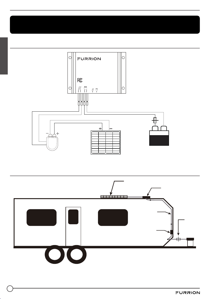
Wiring Diagram
English
Rooftop box
Installation on RV
PWM SOLAR CHARGE
CONTROLLER GEN 2.0
Model: C-FSFP50MAT-A03
System Voltage: 12V
CAUTION: The default setting is for use with
sealed lead-acid batteries. For a dierent
battery type, please refer to the instruction
manual or visit www.furrion.com.
Mode Key
50W Rigid Solar Panel
Fuse
+
12V
Battery
(Fuse and 12V battery
not included.)
50W Rigid Solar Panel
-
Rooftop Box
16AWG Cable
(Inside RV)
PWM Controller
(Inside RV)
(Fuse and 12V battery
not included.)
Fuse
12V
Battery
1. Mount the PWM controller inside of the RV near the battery inside of the front compartment.
2. Connect the battery's positive and negative terminals to the PWM controller battery output
(installer may need to create an exit hole and seal).
15
Page 17
NOTE: Installer will need to provide battery terminal connections and wire to make
connection between PWM controller and battery or batteries.
3. Plug the positive and negative leads from the PV extension cable directly into the Rooftop Box.
4. Identify the positive and negative cables terminated from the Rooftop Box and route them to
the PWM controller for the final connections.
Operation
Suggested Use
1. The PWM controller is intended for a 12 volt battery system.
2. It is advised to install PWM controller in a well ventilated environment as device may become
warm during operation.
3. Choose battery cables with minimum 16AWG gauge rated for 10A DC.
PWM Controller Status Indicators
LED indicators Indications Status Funcitons
Solid on Solar panel has voltage
Charging
Battery
Solid off Solar panel has no voltage
Slow flashing Charging in process
Quick flashing System over voltage
Solid on Normal battery function
Solid off Battery is not connected
Slow flashing Battery is under voltage
Quick flashing Battery is over discharged
English
Mode Selection
Battery Type Selection Method:
● Press the button for 3 seconds. The LED will begin to flash indicating that the mode can be
changed.
● When the button is pressed again the LED number display will change from (1-4).
● When the number value corresponds to the battery type selected by the user, wait until the
LED stops flashing or press the button again for 3 seconds to complete the setting.
Numeric
Indicator
1 Sealed lead-acid batteries 3 Flooded lead-acid batteries
2 GEL lead-acid batteries 4 Lithium iron phosphate batteries
NOTE: Default setting: Sealed lead-acid batteries.
Battery Type
Numeric
Indicator
Battery Type
16
Page 18
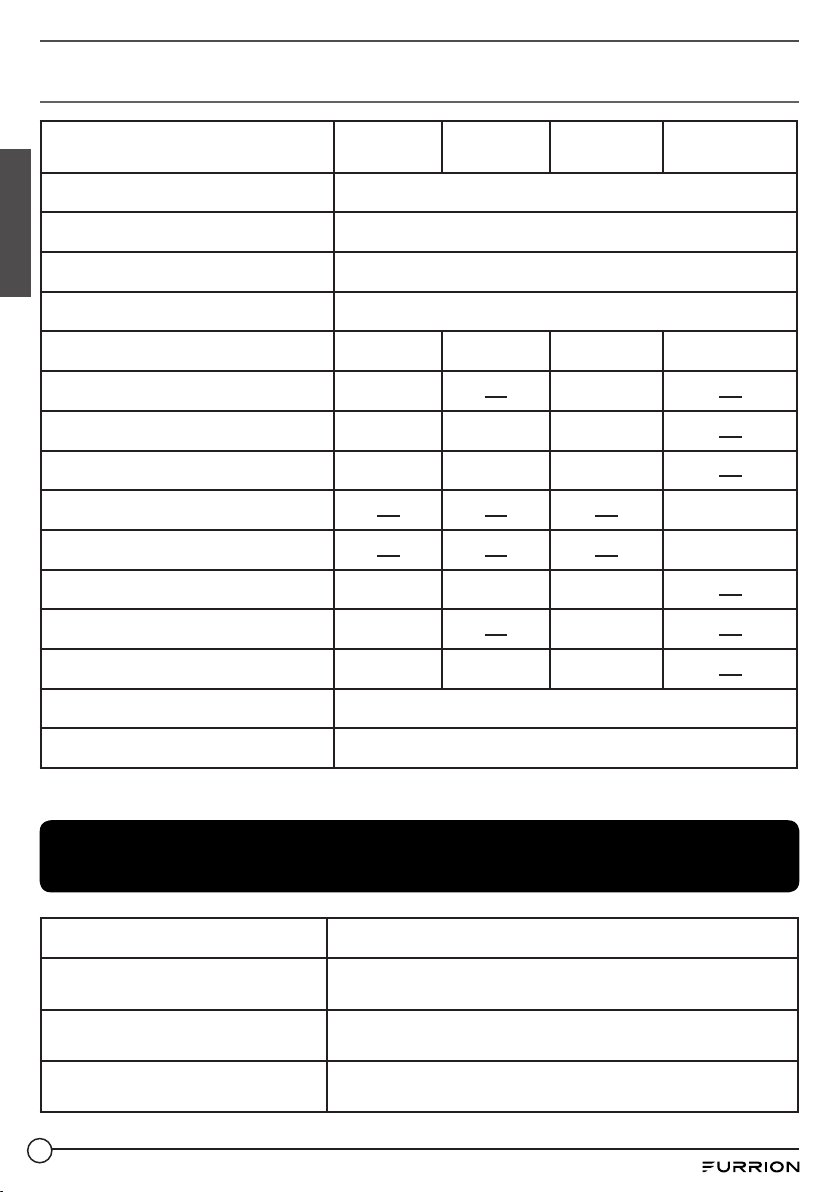
Charging Parameters
Battery Type Sealed GEL Flooded
System current 10A
No-load loss 10mA/12V
English
Solar energy input voltage <55V
System voltage 12V
Overvoltage protection 17.0V 17.0V 17.0V 16.6V
Equalizing charging voltage 14.6V 14.8V
Boost charging voltage 14.4V 14.2V 14.6V
Floating charging voltage 13.8V 13.8V 13.8V
Constant charge voltage 14.6V
Constant charge recovery voltage 13.6V
Boost charging recovery voltage 13.2V 13.2V 13.2V
Equalizing charging duration 1 hour 1 hour
Boost charging duration 4 hours 4 hours 4 hours
Lithium iron
Operation temperature -31oF to 149oF (-35oC to 65oC)
phosphate
Protection degree IP65
NOTE: Charging parameters may vary based on availability of sunlight on the solar panels.
Troubleshooting
Symptoms Causes and Solutions
While sunlight is present, the solar
panel indicator does not light up.
The solar panel charging indicator
is flashing quickly.
The battery indicator does not
light up.
17
Check whether the solar panel is correctly connected
and contact is adequate.
Ensure that the correct battery type has been selected.
The battery may be failing to supply power. Check
whether the battery is correctly connected.
Page 19

The battery indicator is flashing
quickly, and there is no output.
Battery voltage is low.
The battery is over-discharged and will recover when
recharged adequately.
Reposition vehicle if possible to provide more direct
sunlight. If PWM Battery Maintainer can not sustain
adequate charge to the battery, connect the coach to shore
power or generator. Reducing electrical loads in the coach
will also help maintain adequate charge of the battery.
Maintenance
Maintaining Solar Panel
To ensure optimum performance, Furrion recommends the following maintenance measures:
● Clean the glass surface of the solar panel when required. Always use clean water and a soft
sponge or cloth for cleaning. A mild, non-abrasive cleaning agent may be used to remove
stubborn dirt. Do not use cold water to clean panel if the surface is extremity hot as rapid
temperature change could lead to cracking.
● Clean solar panel more frequently during drier months, as they may become covered in dust
more quickly. A pressure washer is not recommended.
● Check the electrical, grounding, and mechanical connections every six months to verify that
they are clean, secure, undamaged, and free of corrosion.
● Remove snow, ice, or other debris when build up occurs.
● Caution: Observe the maintenance instructions for all components used in the system, such
as support frames, PV connectors, charge controller, batteries, etc.
English
Maintaining Multiple Batteries
To properly maintain multiple batteries they should be the same type (gel, flooded or AGM) and
condition. Always connect batteries in parallel (negative to negative and positive to positive)
to maintain a 12V system. Never connect batteries at different states of charge or voltage.
The charged battery will rapidly transfer energy to the discharged battery possibly causing
catastrophic failure.
Long Term RV Storage
If your RV will be stored in extremely cold climates you may need to remove your batteries to
prevent them from freezing. Please note if your solar panel(s) are covered by snow they will
not produce power and can not be depended upon to keep the batteries charged. For battery
storage in mild climates solar system will provide more power provided sufficient sunlight and
limited load. Make sure that all passive/phantom loads are removed from the batteries, i.e. DVD
players, clock radio, etc. to make sure the solar panel(s) can keep the batteries charged even
with reduced sun exposure.
18
Page 20

Merci d’avoir acheté ce produit Furrion®. Avant d’utiliser ou d’installer votre nouveau produit,
veuillez lire attentivement les présentes instructions. Le présent manuel d’instructions contient des
informations permettant une utilisation, une installation et un entretien en toute sécurité du produit.
Veuillez conserver le présent manuel d’instructions en lieu sûr afin de pouvoir vous y référer
ultérieurement. Veillez à transmettre le présent manuel à tout nouveau propriétaire de ce produit.
Le fabricant décline toute responsabilité pour tous dommages résultant du non-respect des
présentes consignes.
Déclaration de conformité du fournisseur
47 CFR § 2.1077 Informations de conformité
Français
Identificateur unique
Nom commercial : Furrion
N° de modèle : C-FSFP50MAT-A03
Partie responsable – Coordonnées de la personne-ressource aux
États-Unis
Furrion Innovation Center & Institute of Technology 52567 Independence Ct,
Elkhart, IN 46514, USA
États-Unis Numéro de téléphone gratuit : 1-888-354-5792;
Courriel : support@furrion.com
Déclaration de conformité FCC
Cet appareil est conforme à l'article 15 du Règlement de la FCC. Son utilisation
est assujettie aux deux conditions suivantes : (1) Cet appareil ne doit pas causer
d'interférences nuisibles, et (2) cet appareil doit accepter toute autre interférence
reçue, y compris les interférences pouvant entraîner un fonctionnement non désiré.
19
Page 21

Table des matières
Table des matières ..................................................................................................... 20
Explication des symboles ......................................................................................... 21
Général ........................................................................................................................ 21
Mesures de sécurité pour l'installation d'un système photovoltaïque ..........................22
Précautions de sécurité lors de la manipulation des batteries ........................................ 23
Remarques d’ordre général concernant l’installation .......................................................... 23
Présentation du produit ............................................................................................ 23
Panneau solaire rigide de 50W .....................................................................................................23
Boîte de toit ............................................................................................................................................. 25
Régulateur de modulation de largeur d'impulsion (MLI) de 10A .................................... 25
Ensemble d'installation pour support en Z ...............................................................................27
Avant l'utilisation ........................................................................................................ 27
Contenu de l’emballage ..................................................................................................................... 27
Installation .................................................................................................................. 28
Fixation du support en Z sur le cadre du panneau solaire ................................................. 28
Installation du panneau solaire sur la surface de montage ............................................... 29
Installation du boîtier de toit ............................................................................................................31
Installation du régulateur à modulation de largeur d'impulsion (MLI) ........................... 32
Branchement .............................................................................................................. 34
Schéma de câblage............................................................................................................................. 34
Installation sur véhicule récréatif ...................................................................................................35
Utilisation .................................................................................................................... 35
Utilisation recommandée ..................................................................................................................35
Témoins d'état du régulateur MLI ..................................................................................................35
Sélection du mode ............................................................................................................................... 36
Paramètres de chargement ............................................................................................................. 36
Dépannage .................................................................................................................. 37
Entretien ...................................................................................................................... 38
Français
20
Page 22

Explication des symboles
Le présent manuel contient des consignes de sécurité et des instructions visant à vous
aider à éliminer ou à réduire tout risque d’accidents et de blessures. Respectez toujours les
avertissements de sécurité identifiés par les symboles suivants. Les sections de sécurité
suivantes indiquent le degré de risque de blessures ou de dommages matériels.
DANGER
Indique une situation de danger immédiat qui, si elle n’est pas évitée, provoque des blessures
graves, voire la mort.
Français
Indique une situation de danger potentiel qui, si elle n’est pas évitée, peut provoquer des
blessures graves, voire la mort.
AVERTISSEMENT
ATTENTION
Indique une situation de danger potentiel qui, si elle n’est pas évitée, peut provoquer des
blessures corporelles mineures ou modérées ou des dommages matériels.
Général
Veuillez lire attentivement les consignes d’installation et de sécurité suivantes. Le non-respect
des présentes instructions est susceptible d’entraîner l’annulation de la garantie du produit.
Ce guide contient des informations concernant l'installation et la manipulation en toute sécurité
des panneaux et des composants solaires Furrion. Toutes les instructions doivent être lues et
comprises avant de tenter l’installation. Si vous avez des questions, veuillez prendre contact
avec votre détaillant ou avec Furrion pour obtenir de plus amples informations.
L'installateur doit se conformer à toutes les mesures de sécurité indiquées dans le guide lors
de l'installation des panneaux solaires. Avant l’installation du système solaire photovoltaïque,
l’installateur doit se familiariser avec les exigences mécaniques et électriques du système
photovoltaïque. Conservez ce manuel en lieu sûr pour toute référence ultérieure.
● L'installation de systèmes solaires photovoltaïques (PV) exige des compétences et des
connaissances spécialisées. L’installateur assume tous les risques de blessures, y compris
le risque de choc électrique. L'installation des panneaux solaires peut se faire uniquement
par des personnes qualifiées.
● Tous les panneaux solaires sont livrés avec une boîte de jonction fixée de façon permanente.
Votre détaillant peut vous offrir des extensions de câble pour simplifier le câblage du module.
● Faites preuve de prudence lors du câblage et de la manipulation de panneaux solaires
exposés aux rayons du soleil.
● Ne connectez et ne déconnectez pas les câbles fixés sur les panneaux solaires lorsqu'ils
sont exposés aux rayons du soleil, sans quoi un arc électrique est susceptible de se
21
Page 23

former. Les arcs électriques peuvent occasionner des brûlures, des incendies ou tout
autre problème de sécurité. Faites toujours preuve de prudence lorsque vous connectez et
déconnectez les câbles des panneaux solaires.
● Les modules solaires photovoltaïques convertissent l’énergie de la lumière en courant
continu électrique et sont conçus pour une utilisation extérieure. La conception de la
structure de support est la responsabilité du concepteur et de l’installateur du système.
● Ne tentez pas de démonter le panneau solaire et ne retirez pas les plaques signalétiques ou
les éléments fixés dessus. Cela annulera la garantie.
● N'appliquez pas de peinture ou d'adhésif sur le panneau solaire.
● N'utilisez pas de miroirs ou d'autres équipements pour concentrer artificiellement les rayons
du soleil sur le panneau solaire.
● Lors de l'installation de panneaux solaires, respectez tous les codes et règlements locaux,
régionaux et nationaux applicables. Obtenez un permis pour l’installation électrique ou de
construction lorsque requis.
Travaillez en toute sécurité
● Pendant l'installation, portez des lunettes de protection et des vêtements appropriés. Faites
preuve d’une extrême prudence lorsque vous travaillez avec l'électricité et autour des
batteries. Utilisez uniquement des outils isolés correctement.
● Faites preuve de prudence lorsque vous travaillez sur le toit d'un véhicule récréatif. Utilisez
toujours des harnais de sécurité et des échelles homologués pendant l'installation et l'entretien.
Mesures de sécurité pour l'installation d'un système
photovoltaïque
Français
● Les panneaux solaires produisent de l'énergie électrique lorsqu'ils sont exposés au soleil.
● Maintenez les enfants bien à l’écart du système lors du transport et de l’installation
mécanique et électrique des composants.
● Recouvrez complètement tous les panneaux solaires d'un matériel opaque durant
l'installation, afin d'empêcher toute production d'électricité.
● Ne pas porter de bagues métalliques, de montres, ou tout autre accessoire métallique lors
de l’installation ou de la résolution de problèmes du système photovoltaïque.
● Utilisez un équipement de protection approprié (outils isolés, gants isolés, etc.) certifié pour
une utilisation sur des installations électriques.
● Respectez les instructions et les mesures de sécurité pour tout autre composant utilisé
dans le système, notamment les câbles et connexions, les raccords, les disjoncteurs CC, les
pièces d'installation, les inverseurs, etc.
● N'utilisez que de l'équipement, des connecteurs, du câblage et du matériel d'installation
appropriés pour l'utilisation dans un système photovoltaïque.
● Utilisez toujours le même type de panneaux solaires dans un système photovoltaïque particulier.
● Dans des conditions de fonctionnement normales, les panneaux solaires produisent des
tensions et des voltages susceptibles de varier par rapport à ceux indiqués dans la fiche
technique. Les valeurs de la fiche technique sont uniquement applicables lors de conditions
normales d’essai.
● Le courant de court-circuit et les tensions à circuit ouvert doivent être multipliés par un
coefficient de 1,25 afin de déterminer la tension/ampacité nominale du système pour les
fusibles et les régulateurs de charge.
22
Page 24

Précautions de sécurité lors de la manipulation des
batteries
● Les batteries contiennent de l'acide sulfurique dilué très corrosif servant d'électrolyte.
Des précautions doivent être prises afin d'éviter tout contact avec la peau, les yeux ou les
vêtements.
● Pendant le chargement, les batteries génèrent de l'hydrogène et de l'oxygène, ce qui peut
former un mélange gazeux explosif.
● Entreposez les batteries dans un endroit bien ventilé et suivez les recommandations du
fabricant. Ne fumez jamais et ne produisez jamais d'étincelles ou de flammes à proximité des
batteries.
● Ne laissez jamais un objet étranger tomber ou reposer sur la batterie. Cela est susceptible
d’entraîner un incendie, une explosion ou un émanation de gaz nocifs.
● Retirez les objets métalliques tels que les bagues, les bracelets et les montres lorsque vous
travaillez avec des batteries. Les batteries peuvent produire un courant de court-circuit
Français
suffisamment élevé pour souder un anneau ou un objet similaire sur le métal, provoquant une
grave brûlure.
● Retirez toujours en premier la borne négative de la batterie lorsque vous devez la retirer.
● Utilisez uniquement des outils correctement isolés pour effectuer les connexions de la
batterie.
Remarques d’ordre général concernant l’installation
● Les trous de drainage ne doivent pas être couverts par le système d'installation. Le panneau
solaire doit être monté avec la surface vitrée orientée vers le haut.
● Ne soulevez pas le panneau solaire par la boîte de jonction ou les fils électriques.
● Ne vous tenez pas debout et ne marchez pas sur le panneau solaire.
● Ne faites pas tomber le panneau solaire et ne laissez pas tomber des objets sur le panneau
solaire.
● Ne placez pas d'objets lourds sur le panneau solaire.
Présentation du produit
Panneau solaire rigide de 50W (C-FSFP50MAT-A01 /
C-FSFP50MAT-001)
Les panneaux solaires Furrion sont faits de cellules solaires monocristallines en série à
rendement élevé, avec un taux de transmission élevé, un verre trempé à faible teneur en fer, un
film anti-âge d'éthylène-acétate de vinyle (EVA), un laminé avec TPT ignifuge et des cadres en
alliage d'aluminium anodisé. Ils sont conçus pour une installation facile, une longévité étendue et
une résistance contre les dommages causés par les vents forts ou les grêlons.
23
Page 25

26⁄” (670mm)
(123mm)
1⁄” (30mm)
4⁄”
(123mm)
35⁄” (900mm)
21⁄” (540mm)
4⁄”
Caractéristiques
Puissance Maximale (Pmax): 50W
Tension d'alimentation maximale (Vmp) 18,5V
Puissance maximale du courant (Imp) 2 ,7A
Tension en circuit ouvert (Voc) 22,6V
Courant de court-circuit 2,9A
Efficacité des cellules 18%
Type de cellule Monocristallin
Tension maximale du système 36V CC
Tolérance d'alimentation ± 5%
Calibre des fusibles de série 5A
Coefficient de température (Puissance) -0,43%/°C
Coefficient de température (Tension) -0,32%/°C
4*⁄” (6mm)
Français
Coefficient de température (Courant) +0,02%/°C
NOCT (Air 20°C, Sun 0,8kW/m², Wind 1m/s) 45±3°C
Poids 9,26lb (4,2kg)
Câble 2,5mm2, PV1-F, 35⅜”(900mm)
Connecteur Fil isolé
Cadre Aluminium anodisé (noir)
Température de fonctionnement -40°F à 185°F (-40°C à 85°C)
Indice IP IP65
24
Page 26

Boîte de toit (C-FSFP50MAT-A02 / C-FSFP50MAT-002)
● IP65 résistant à la poussière et à l'eau.
● Conçu pour être monté avec du scellant adhésif ou des vis à tête ronde standard no 8 RV
(non incluses).
● Construit avec un agent anti-UV afin d’augmenter la résistance aux intempéries et de réduire
les changements de couleur pendant les longues périodes d'exposition aux éléments.
Français
Caractéristiques
Matériel Construit avec un agent anti-UV
Dimensions (LxHxP) 5⅛pox1¾pox3⅝po (130x43x93mm)
Indice IP IP65
Régulateur de modulation de largeur d'impulsion (MLI)
de 10A (C-FSFP50MAT-A03 / C-FSFP50MAT-003)
● IP65 résistant à la poussière et à l'eau.
● Tension du système: 12V.
● Écran numérique à DEL et bouton de sélection du mode.
● L'algorithme intelligent de chargement MLI à 3niveaux applique des modes d'égalisation, de
surcharge et de lancement variables.
● Le profil de chargement intelligent garantit que les batteries sont complètement rechargées,
équilibrées et désulfurées, prolongeant ainsi leur durée de vie.
● Les options du programme de chargement sont disponibles pour les batteries scellées, GEL,
les batteries au plomb, ou au phosphate de fer-lithium.
● La mémoire du régulateur conserve les informations relatives au mode et au type de batterie,
ce qui rend l'utilisation simple et pratique.
● Protection contre les surcharges et l'inversion de polarité.
25
Page 27

PWM SOLAR CHARGE
CONTROLLER GEN 2.0
Model: C-FSFP50MAT-A03
System Voltage: 12V
CAUTION: The default setting is for use with
sealed lead-acid batteries. For a dierent
battery type, please refer to the instruction
manual or visit w ww.furrion.com.
Mode Key
5 6 7 8
1 2 3 4
1 Fil d’entrée solaire positive 5 Témoin de chargement
2 Fil d'entrée solaire négative 6 Témoin de la batterie
3 Borne de sortie positive de la batterie 7 Indicateur du mode
4 Borne de sortie négative de la batterie 8 Bouton de sélection du mode
Caractéristiques
Câble de raccordement pour le panneau solaire 14AWG, 23⅝" (600mm)
Câble de raccordement pour la batterie 14AWG, 23⅝" (600mm)
Connecteur Fil isolé
Dimensions (LxHxP) 3¼pox⁄pox2⁄” (82x20x58mm)
Température de fonctionnement -31°F à 149°F (-35°C à 65°C)
Français
Indice IP IP65
26
Page 28

Ensemble d'installation pour support en Z
(C-FSFP50MAT-A04 / C-FSFP50MAT-004)
● Structure en aluminium avec écrous, boulons et rondelles en acier inoxydable.
● Installation facile et sans entretien.
Français
x4
Caractéristiques
Dimensions (par support) (LxHxP) 3⁄pox1⅝pox3⅞po (88x42x100mm)
Support en Z en aluminiumx4
Ensemble d'installation pour support en Z
comprend
REMARQUE: Cet ensemble n'inclut PAS la quincaillerie pour fixer les supports en Z sur le toit.
Vis à tête hexagonale M6 SS304x20mmx4
Écrou M6 SS304x4
Rondelle de sécurité fendue M6 SS304x4
Rondelle plate M6 SS304x8
Avant l'utilisation
Contenu de l’emballage
Assurez-vous que tous les éléments suivants sont présents dans l'emballage. Si un élément est
endommagé ou manquant, contactez votre revendeur.
● Panneau solaire rigide de 50Wx1
● Boîte de toitx1
● Régulateur MLIx1
● Ensemble d'installation pour support en Zx1
● Manuel d'utilisationx1
● Livret de garantie x 1
27
Page 29

Installation
Écrou M6
Boulon
hexagonal M6
Rondelle de
sécurité fendue M6
Rondelle plate M6
Rondelle plate M6
Fixation du support en Z sur le cadre du panneau solaire
1. Apposez le support en Z sur le côté le plus court du cadre du panneau solaire. Assurez-vous
que le pied d'installation du support en Z est orienté vers l'extérieur par rapport au cadre du
panneau solaire.
2. Alignez le trou d'installation du support en Z sur celui du cadre du panneau solaire.
-
+
Français
3. Fixez le support en Z sur le cadre du panneau solaire.
-
+
28
Page 30

4. Répétez les étapes ci-dessus pour chaque support en Z.
-
+
Installation du panneau solaire sur la surface de
Français
montage
Sélection de l’emplacement de montage
● Sélectionnez un emplacement approprié pour l'installation du panneau solaire.
● Installez le panneau solaire dans un espace dégagé sur le toit du véhicule récréatif, afin
d'obtenir une exposition maximale au soleil.
● Les panneaux solaires doivent être installés aussi loin que possible des obstructions du toit
(climatiseurs, évents de plomberie, puits de lumière, etc.).
● Si le panneau solaire doit être installé à proximité d’une obstruction du toit, essayez
d'orienter les modules de façon à ce que le côté le plus large soit orienté vers l'obstruction.
Sélection de la structure de montage et du matériel approprié
● Suivez toutes les instructions et mesures de sécurité fournies avec le système d'installation
à utiliser avec le panneau solaire.
● Ne percez pas de trous dans la surface vitrée du panneau solaire. Cela annulera la garantie.
● Ne percez pas de trous de fixation supplémentaires dans le cadre du panneau solaire. Cela
annulera la garantie.
● Pour une installation normale, les panneaux solaires doivent être solidement fixés sur la
structure de montage à l'aide de quatre points d'installation.
● La structure de montage et la quincaillerie doivent être composées de matériaux durables,
résistants à la corrosion et aux rayons UV.
● Sélectionnez un emplacement de montage permettant d’aligner les trous du support de
montage du panneau solaire sur le cadrage structurel du toit.
Installation de panneaux solaires
● Dans les régions sujettes aux fortes chutes de neige en hiver, sélectionnez la hauteur du
système de montage de façon à ce que le bord inférieur du panneau solaire ne soit pas
recouvert de neige pendant une période prolongée.
● Les panneaux solaires doivent être solidement fixés sur la structure de montage.
● Prévoyez une ventilation adéquate sous le panneau solaire.
29
Page 31

● Avant d'installer des panneaux solaires sur un toit, assurez-vous que la construction du toit
(Attaches non
incluses, vis # 10
recommandées)
est appropriée. En outre, toute ouverture de la toiture nécessaire à l’installation du panneau
solaire doit être correctement scellée afin d’éviter des fuites.
● La finition sous les panneaux doit toujours être exempte de tout objet étranger ou élément
structurel susceptible d’entrer en contact avec le panneau, en particulier lorsque celui-ci est
soumis à une charge mécanique.
● Assurez-vous que les panneaux ne sont pas soumis à des vents ou à une charge de neige
supérieure à la charge maximale admissible (176lb/80kg), ou à des forces excessives dues
à la dilatation thermique de la structure porteuse.
Installation
1. Fixez les panneaux sur le toit en vissant la quincaillerie d'installation appropriée à travers les
trous du support en Z. Installez le panneau solaire sur une surface relativement plane du toit.
REMARQUE:
● Assurez-vous que l’emplacement des vis est soutenu par une structure solide, telle qu’un
chevron, un montant, etc.
● Appliquez de l'adhésif auto-nivelant (non inclus) sur la partie inférieure des supports en Z
afin de créer une étanchéité à l'eau.
2. Montez le panneau solaire de sorte qu'au moins 2pieds soient vissés dans le métal ou dans
les poutres de charpente en bois.
3. Répétez l'opération pour tous les points de fixation.
Français
30
Page 32

4. Scellez les bords de tous les supports en Z et de toutes les vis aux endroits où ils entrent en
contact avec la surface d'installation ou la traversent.
REMARQUE: Assurez-vous que l'adhésif en silicone auto-nivelant est appliqué
uniformément sur tous les bords du support et des vis de montage, sans aucun espace.
Installation du boîtier de toit
1. Si désiré, percez un petit trou de guidage à l'emplacement sélectionné. Élargissez le trou de
guidage à l’aide d’une mèche appropriée. Le trou percé doit être suffisamment large pour
Français
que les câbles puissent passer à travers.
2. Limez et éliminez les arêtes vives autour du trou qui ont été créées lors du perçage. Nettoyez
soigneusement la zone de montage afin d’assurer une bonne tenue du produit d'étanchéité.
3. Insérez les câbles PV positifs/négatifs de la boîte de connexion du panneau solaire dans les
trous filetés des câbles enfichables du boîtier de toit.
4. Fixez les câbles PV positif/négatif («+» et «-» indiqués sur la bande à la fin) à l'intérieur du
boîtier de toit sur les câbles connectés au régulateur MLI à l’aide des connecteurs à vis/
Marrettes (non fournis).
5. Utilisez des vis à tête ronde standard no 8 (non fournies) pour fixer le boîtier de toit au toit du
VR en perçant les 3trous de vis sur le périmètre de la base du boîtier de toit.
31
Page 33

6. Utilisez un scellant de silicone auto-nivelant approprié, tel que recommandé par votre
concessionnaire ou fabricant de véhicules récréatifs, afin de bien sceller le périmètre du
boîtier de toit.
REMARQUE:
● Serrez les câbles enfichables sur le boîtier de toit.
● Appliquez de l'adhésif auto-nivelant (non fourni) sur le trou de montage.
Installation du régulateur à modulation de largeur
d'impulsion (MLI)
1. Montez le régulateur MLI sur une surface plane à l'intérieur du véhicule récréatif à l’aide de
4vis (non incluses, #3 recommandé).
2. Montez le régulateur MLI près de la batterie à l'intérieur du compartiment frontal du véhicule
récréatif.
Français
3. Branchez les câbles positif/négatif de la batterie du régulateur MLI sur les câbles positif/
négatif (non inclus) de la batterie à l'aide de connecteurs/Marrettes à vis (non inclus).
4. Raccordez les câbles positif/négatif (non inclus) du boîtier de toit aux fils solaires positif/
négatif du régulateur MLI à l'aide de connecteurs/Marrettes à vis (non inclus).
32
Page 34

Français
5. Assurez-vous qu’une connexion électrique appropriée est établie avec la batterie en utilisant
des connecteurs de fils torsadés / Marrettes (non fournis) et des connecteurs à bague de
sertissage (ou similaire) pour la connexion aux bornes de la batterie.
6. Fixez et sécurisez tous les câbles détachés conformément au code électrique approprié.
7. Il est recommandé d'installer un fusible en ligne de 10A du côté positif de la batterie à moins
de 7pouces de la borne positive.
REMARQUE:
● Il est recommandé de connecter d'abord les fils de sortie de la pile PWM à la pile et ensuite
de connecter les fils d'entrée solaire aux fils du panneau solaire.
● Ne court-circuitez pas les fils de sortie de la pile du PWM, car cela pourrait endommager le
contrôleur PWM et/ou la pile.
Calibre des fils PV/piles
Comme le courant de sortie solaire peut varier en fonction des méthodes de connexion des
panneaux solaires, de la lumière du soleil et de la température, le calibre minimal du fil doit être
conforme au courant de court-circuit maximal du panneau. Les fils d'entrée et de sortie du PWM
auront la même tension et le même courant. Par conséquent, le calibre du fil entre le panneau
solaire et le PWM et entre le PWM et la pile doit être le même. Veuillez vous référer au tableau de
calibre de fil suivant pour référence:
Longueur de câble
avec chute de tension
de 10%.
0à20pi 0à6pi 16 AWG 16 AWG
30pi 10 pi 16 AWG 14 AWG
50 pi 15 pi 16 AWG 12 AWG
65 pi 20 pi 14 AWG 10 AWG
80 pi 25 pi 12 AWG 10 AWG
33
Longueur de câble
avec chute de tension
de 3%.
Jauge à fil avec
courant PV maximum
5A
Jauge à fil avec
courant PV maximum
10A
Page 35

REMARQUE: Le calibre du fil n'est fourni qu'à titre de référence. En cas de distance importante
entre le système PV et le contrôleur, des fils plus gros peuvent être utilisés pour réduire la chute
de tension et améliorer les performances. Comme illustré, une longueur de fil plus courte et
un calibre de fil plus large peuvent diminuer la chute de tension entre le panneau solaire et le
contrôleur PWM.
Consignes de réglage MLI
1. Appuyez sur la touche de sélection de mode pendant 3secondes pour accéder au mode de
sélection des piles.
2. Appuyez sur le bouton de sélection du mode jusqu'à ce que la valeur numérique
correspondant à la bonne batterie s'affiche sur l'écran DEL.
3. Une fois que le type de pile correct est sélectionné, appuyez sur la touche de sélection de
mode pendant 3secondes pour quitter le mode de sélection de pile.
REMARQUE: Pour le mode de sélection des piles, veuillez consulter la section Sélection du mode.
ATTENTION
Le réglage par défaut est destiné à être utilisé avec des batteries plomb-acide scellées. Pour
un type de batterie différent, veuillez vous reporter au manuel d'utilisation ou visiter le site
www.furrion.com.
Branchement
Schéma de câblage
Français
Boîte de toit
PWM SOLAR CHARGE
CONTROLLER GEN 2.0
Model: C-FSFP50MAT-A03
System Voltage: 12V
CAUTION: The default setting is for use with
sealed lead-acid batteries. For a dierent
battery type, please refer to the instruction
manual or visit www.furrion.com.
Mode Key
Panneau solaire rigide de 50W
Fusible
+
Batterie
de 12V
(Fusible et batterie de
12V non inclus)
-
34
Page 36

Installation sur véhicule récréatif
Panneau solaire rigide de 50W
Boîte de toit
Câble 16AWG
(à l’intérieur
du véhicule
récréatif)
Régulateur MLI (à
l’intérieur du
véhicule récréatif)
(Fusible et batterie de
12V non inclus)
Français
1. Montez le régulateur MLI à l'intérieur du véhicule récréatif près de la batterie à l'intérieur du
compartiment avant.
2. Connectez les bornes positive et négative de la batterie à la sortie de la batterie du
régulateur MLI (l'installateur devra peut-être créer un trou de sortie et le rendre étanche).
REMARQUE: L'installateur devra fournir les connexions des bornes de batterie et le câble
afin d'établir la connexion entre le régulateur MLI et la ou les batterie(s).
3. Branchez les fils positif et négatif du câble d'extension photovoltaïque directement dans le
boîtier du toit.
4. Identifiez les fils positifs et négatifs du boîtier du toit et acheminez-les vers le régulateur MLI
pour les connexions finales.
Fusible
Batterie
de 12V
Utilisation
Utilisation recommandée
1. Le régulateur MLI est conçu pour un système de batterie de 12volts.
2. Il est recommandé d'installer le régulateur MLI dans un environnement bien ventilé, car
l'appareil est susceptible de chauffer pendant le fonctionnement.
3. Choisissez des câbles de batterie ayant un calibre minimum de 16AWG pour 10A CC.
Témoins d'état du régulateur MLI
Témoins DEL Indications État Fonctions
Allumé fixe Le panneau solaire est sous tension
Chargement
35
Éteint Le panneau solaire est hors tension
Clignotement lent Chargement en cours
Clignotement rapide Surtension du système
Page 37

Allumé fixe Fonction de batterie normale
Batterie
Éteint Batterie non connectée
Clignotement lent Batterie sous tension
Clignotement rapide Batterie trop déchargée
Sélection du mode
Méthode de sélection du type de batterie:
● Appuyez sur le bouton pendant 3secondes. Le voyant DEL commence à clignoter pour
indiquer que le mode peut être modifié.
● Lorsque vous appuyez à nouveau sur le bouton, l'affichage DEL du nombre change de 1à4.
● Lorsque la valeur numérique correspond au type de pile sélectionné par l'utilisateur,
attendez que la DEL cesse de clignoter ou appuyez à nouveau sur le bouton pendant
3secondes pour terminer la configuration.
Français
Indicateur
numérique
1
2
REMARQUE: Réglage par défaut: Batteries plomb-acide scellées.
Type de batterie
Batteries scellées au plombacide
Batteries au plomb-acide
gélifié
Indicateur
numérique
3 Batteries plomb-acide inondées
4
Type de batterie
Batteries au phosphate de fer et
de lithium
Paramètres de chargement
Type de batterie Scellé
Courant du système 10A
Perte à vide 10mA/12V
Tension d'entrée d'énergie solaire <55V
Tension du système 12V
Dispositif de protection contre les
surtensions
Tension de charge d'égalisation 14,6V 14,8V
Tension de charge d’amplification 14,4V 14,2V 14,6V
17,0V 17,0V 17,0V 16,6V
À électrolyte
gélifié
À électrolyte
liquide
Lithium fer
phosphate
Tension de charge flottante 13,8V 13,8V 13,8V
Tension de charge constante 14,6V
36
Page 38

Tension de récupération de
charge constante
Tension de récupération de
charge d’amplification
Durée de charge d'égalisation 1heure 1heure
Durée de charge d’amplification 4heures 4heures 4heures
13,2V 13,2V 13,2V
13,6V
Température de
fonctionnement
-31oF à 149oF (-35oC à 65oC)
Degré de protection IP65
REMARQUE: Les paramètres de chargement sont susceptibles de varier en fonction de la
disponibilité de la lumière solaire sur les panneaux solaires.
Français
Dépannage
Symptômes Causes et solutions
En présence de rayons du soleil,
l’indicateur du panneau solaire ne
s’allume pas.
L'indicateur de chargement du
panneau solaire clignote rapidement.
L'indicateur de batterie ne s'allume
pas.
L'indicateur de batterie clignote
rapidement et il n'y a pas de sortie.
La tension de la batterie est faible
Vérifiez si le panneau solaire est correctement
connecté et si le contact est adéquat.
Assurez-vous que le bon type de batterie a été
sélectionné.
La batterie ne parvient peut-être pas à s’alimenter.
Vérifiez si la batterie est correctement connectée.
La batterie est trop déchargée et se rétablira une fois
correctement rechargée.
Si possible, déplacez le véhicule afin d'avoir plus de
lumière solaire directe.
Si le mainteneur de batterie MLI ne peut pas soutenir
une charge adéquate de la batterie, connectez le
véhicule à l'alimentation au sol ou à la génératrice. La
réduction des charges électriques dans le véhicule
permet également de maintenir un chargement
adéquat de la batterie.
37
Page 39

Entretien
Entretien du panneau solaire
Afin d'assurer une performance optimale, Furrion recommande les mesures d'entretien
suivantes:
● Nettoyez la surface vitrée du panneau solaire si nécessaire. Utilisez toujours de l’eau propre
et une éponge ou un linge doux pour effectuer le nettoyage. L’utilisation d’un produit doux
et non abrasif est acceptable pour nettoyer la saleté tenace. N'utilisez pas d'eau froide
pour nettoyer le panneau si la surface est très chaude, car un changement brusque de
température est susceptible d’entraîner des fissures.
● Nettoyez le panneau solaire plus fréquemment pendant les mois les plus secs, car il peut se
couvrir de poussière plus rapidement. Un nettoyage à pression n'est pas recommandé.
● Inspectez les connexions électriques et mécaniques ainsi que la mise à la terre tous les six
mois afin de vérifier leur état de propreté, qu’elles sont sécuritaires, non endommagées et
sans corrosion.
● Retirez la neige, la glace et tout autre débris en cas d'accumulation.
● Avertissement: Respectez les instructions d'entretien de tous les composants utilisés dans
le système, tels que les cadres de support, les connecteurs PV, le régulateur de chargement,
les batteries, etc.
Entretien des batteries multiples
Pour entretenir correctement plusieurs batteries, celles-ci doivent être du même type (gélifiées,
inondées ou AGM) et dans le même état. Connectez toujours les batteries en parallèle (négatif
sur négatif et positif sur positif) pour maintenir un système de 12V. Ne jamais connecter des
batteries avec des états de charge ou de tension différents. La batterie chargée transférera
rapidement de l'énergie à la batterie déchargée, ce qui pourrait occasionner une panne
désastreuse.
Français
Entreposage à long terme du véhicule récréatif
Si votre véhicule récréatif doit être entreposé dans des climats extrêmement froids, vous
devrez peut-être retirer vos batteries afin de les empêcher de geler. Veuillez noter que si vos
panneaux solaires sont recouverts de neige, ils ne produiront pas d'électricité et ne serviront
pas à maintenir les batteries chargées. Dans les climats doux, le système solaire fournira plus
d'énergie si la lumière du soleil est suffisante et si la charge est limitée. Assurez-vous que toutes
les charges passives/fantômes sont retirées des batteries (par ex. lecteurs DVD, radio-réveil,
etc.) afin de vous assurer que le(s) panneau(x) solaire(s) peu(ven)t maintenir les batteries
rechargées même avec une exposition réduite au soleil.
38
Page 40

Gracias por comprar este producto de Furrion®. Antes de utilizarlo o instalarlo, lea atentamente
estas instrucciones. Este manual de instrucciones contiene información relativa al uso seguro, a
la instalación y al mantenimiento del producto.
Guarde este manual de instrucciones en un lugar seguro para usarlo como referencia a futuro.
Asegúrese de entregar este manual a los nuevos propietarios del producto.
El fabricante no acepta responsabilidad por daños provocados por no seguir estas
instrucciones.
Declaración de conformidad del proveedor
47 CFR § 2.1077 Información de cumplimiento
Identificador único
Nombre comercial: Furrion
Modelo N.o: C-FSFP50MAT-A03
Parte responsable – Información de contacto en EE. UU.
Español
Furrion Innovation Center & Institute of Technology 52567 Independence Ct.,
Elkhart, IN 46514, USA
Línea gratuita:1-888-354-5792;
Correo electrónico: support@furrion.com
Declaración de cumplimiento con la Comisión Federal de
Comunicaciones (FCC)
Este dispositivo cumple con el Artículo 15 del Reglamento de la Comisión Federal
de Comunicaciones (FCC). Su uso está sujeto a las siguientes dos condiciones: (1)
Este dispositivo no debe causar interferencias perjudiciales, y (2) este dispositivo
debe aceptar cualquier interferencia que reciba, incluidas las interferencias que
puedan causar un funcionamiento no deseado.
39
Page 41

Índice
Índice ........................................................................................................................... 40
Explicación de los símbolos ..................................................................................... 41
General ........................................................................................................................ 41
Precauciones de seguridad para la instalación de un sistema fotovoltaico ..............42
Precauciones de seguridad para el trabajo con baterías ...................................................43
Notas generales de instalación ...................................................................................................... 43
Resumen del producto .............................................................................................. 43
Panel solar rígido de 50W ................................................................................................................ 43
Caja de techo ......................................................................................................................................... 45
Controlador de modulación de ancho de pulso (PWM) de 10A .....................................45
Kit de montaje con soporte en forma de Z ................................................................................47
Antes de usar .............................................................................................................. 47
Contenido ................................................................................................................................................47
Instalación ................................................................................................................... 48
Fije los soportes en forma de Z al marco del panel solar ...................................................48
Instale el panel en la superficie de montaje ..............................................................................49
Instale la caja de techo ......................................................................................................................51
Instale el controlador PWM ..............................................................................................................52
Conexión ..................................................................................................................... 54
Diagrama de cableado ....................................................................................................................... 54
Instalación en casa rodante .............................................................................................................55
Funcionamiento ......................................................................................................... 55
Uso sugerido ..........................................................................................................................................55
Indicadores de estado del controlador PWM .......................................................................... 55
Selección de modo .............................................................................................................................. 56
Parámetros de carga .......................................................................................................................... 56
Resolución de problemas ......................................................................................... 57
Mantenimiento ............................................................................................................ 58
Español
40
Page 42

Explicación de los símbolos
Este manual tiene información de seguridad e instrucciones para ayudarle a eliminar o reducir el
riesgo de accidentes y lesiones. Respete siempre las advertencias de seguridad identificadas
por los siguientes símbolos. Las siguientes frases de seguridad indican el grado de riesgo de
lesión o daños a la propiedad.
PELIGRO
Indica una situación peligrosa que, de no evitarse, provocará la muerte o lesiones graves.
ADVERTENCIA
Indica una situación potencialmente peligrosa que, de no evitarse, podría provocar la muerte
o lesiones graves.
PRECAUCIÓN
Indica una situación potencialmente peligrosa que, de no evitarse, podría provocar lesiones
personales menores o moderadas, o bien daño a la propiedad.
Español
General
Por favor, lea atentamente las siguientes instrucciones de instalación y seguridad. El
incumplimiento de estas instrucciones puede anular la garantía del producto.
Esta guía contiene información sobre la instalación y la manipulación segura de los paneles
solares y Furrion y sus componentes. Se deben leer y comprender todas las instrucciones antes
de iniciar la instalación. Si tiene alguna pregunta, póngase en contacto con su distribuidor o con
Furrion para obtener más información.
El instalador debe cumplir con todas las precauciones de seguridad que aparecen en la guía al
instalar los paneles solares. Antes de instalar un sistema solar fotovoltaico, el instalador debe
familiarizarse con los requisitos mecánicos y eléctricos de los sistemas fotovoltaicos. Guarde
esta guía en un lugar seguro para futuras consultas.
● La instalación de sistemas solares fotovoltaicos (FV) requiere conocimientos
especializados. El instalador asume todo el riesgo de posibles lesiones, incluido el riesgo de
una descarga eléctrica. La instalación de paneles solares debe ser realizada únicamente por
personal cualificado.
● Todos los paneles solares incluyen una caja de conexiones fijada de forma permanente. Su
distribuidor puede proporcionar cables de extensión adicionales para simplificar el cableado
de los módulos.
● Tenga cuidado al cablear o manipular paneles solares expuestos a la luz solar.
● No conecte ni desconecte los cables conectados a los paneles solares cuando estén
expuestos a la luz solar, ya que de lo contrario podría producirse un arco eléctrico. Los arcos
pueden causar quemaduras, incendios u otros problemas de seguridad. Siempre tenga
cuidado al conectar y desconectar el cableado de los paneles solares.
41
Page 43

● Los módulos solares fotovoltaicos convierten la energía luminosa en energía eléctrica de
corriente continua y están diseñados para su uso en exteriores. El diseño adecuado de las
estructuras de soporte es responsabilidad del diseñador e instalador del sistema.
● No intente desmontar el panel solar y no quite ninguna placa de identificación ni ningún
componente que esté fijado al módulo. De lo contrario, la garantía quedará anulada.
● No aplique pintura ni adhesivos al panel solar.
● No utilice espejos ni otro dispositivo para concentrar artificialmente luz solar en el panel
solar.
● Al instalar paneles solares, cumpla con todos los códigos y regulaciones locales, regionales
y nacionales aplicables. Obtenga un permiso de construcción y/o de electricidad cuando
sea necesario.
Trabaje de forma segura
● Use anteojos de protección y ropa adecuada durante la instalación. Tenga extremo
cuidado al trabajar con electricidad y al trabajar en proximidad de baterías. Use únicamente
herramientas con una adecuada aislación.
● Tenga cuidado al trabajar sobre el techo de una casa rodante, siempre use arneses y
escaleras con clasificación de seguridad para realizar la instalación y mantenimiento.
Precauciones de seguridad para la instalación de un
sistema fotovoltaico
● Los paneles solares producen energía eléctrica cuando se exponen a la luz solar.
● Mantenga a los niños alejados del sistema mientras transporta e instala componentes
mecánicos y eléctricos.
● Cubra completamente todos los paneles solares con un material opaco durante la
instalación para evitar que se genere electricidad.
● No utilice anillos metálicos, relojes u otros dispositivos metálicos durante la instalación o
mientras soluciona problemas de los sistemas fotovoltaicos.
● Utilice equipos de seguridad adecuados (herramientas aisladas, guantes aislantes, etc.)
aprobados para su uso en instalaciones eléctricas.
● Cumpla con las instrucciones y precauciones de seguridad de todos los demás
componentes utilizados en el sistema, incluyendo el cableado y los cables, los conectores,
los interruptores de CC, los accesorios de montaje, los inversores, etc.
● Utilice únicamente equipos, conectores, cableado y accesorios de montaje adecuados para
su uso en un sistema fotovoltaico.
● Utilice siempre el mismo tipo de panel solar dentro de un sistema fotovoltaico en particular.
● En condiciones normales de funcionamiento, los paneles solares producen corrientes y
tensiones que podrían ser distintas a las indicadas en la hoja de datos. Los valores de la hoja
de datos son aplicables únicamente en condiciones de prueba estándar.
● Para determinar la calificación de tensión/corriente máxima para los fusibles y
controladores de carga, se debe multiplicar la corriente de cortocircuito y la tensión de
circuito abierto por un factor de 1.25.
Español
42
Page 44

Precauciones de seguridad para el trabajo con baterías
● Las baterías contienen, como electrolito, ácido sulfúrico diluido altamente corrosivo. Se
deben tomar recaudos para evitar el contacto con la piel, los ojos y la ropa.
● Las baterías generan hidrógeno y oxígeno durante la carga, lo que podría formar una mezcla
de gas explosiva.
● Almacene las baterías en un lugar bien ventilado y de acuerdo con las recomendaciones del
fabricante de la batería. Nunca fume ni permita que se generen chispas o llamas cerca de las
baterías.
● Nunca permita que objetos extraños caigan ni queden apoyados sobre la batería. De lo
contrario podría generarse un incendio, explosión o liberación de gases nocivos.
● Quítese cualquier objeto metálico como anillos, pulseras o relojes antes de trabajar con
baterías. Las baterías pueden producir corrientes de cortocircuito suficientemente altas
para soldar un anillo u objeto similar al metal, lo que causaría quemaduras graves.
● Si necesita retirar una batería, siempre retire de la batería el polo negativo primero.
● Use únicamente herramientas con una aislación adecuada al realizar conexiones de la
batería.
Notas generales de instalación
● Los orificios de drenaje no deben ser cubiertos por el sistema de montaje. El panel solar
debe montarse con la superficie de vidrio hacia arriba.
Español
● No levante el panel solar tomándolo por su caja de conexiones o por los cables eléctricos.
● No se pare sobre el panel solar ni lo pise.
● No deje caer el panel solar ni permita que caigan objetos sobre él.
● No coloque objetos pesados sobre el panel solar.
Resumen del producto
Panel solar rígido de 50W (C-FSFP50MAT-A01 /
C-FSFP50MAT-001)
Los paneles solares Furrion están hecho de células solares de silicio monocristalino conectadas
en serie de alta eficiencia, alta tasa de transmisión, vidrio templado con bajo contenido
en hierro, EVA anti envejecimiento, laminado TPT de alta resistencia al fuego y marcos de
aleación de aluminio anodizado. Están diseñados para una fácil instalación, una larga vida útil y
resistencia a los daños causados por fuertes vientos o granizo.
43
Page 45

26⁄” (670mm)
(123mm)
1⁄” (30mm)
4⁄”
(123mm)
35⁄” (900mm)
21⁄” (540mm)
4⁄”
Especificaciones
Potencia máxima (Pmax) 50W
Tensión a potencia máxima (Vmp) 18.5V
Corriente a potencia máxima (Imp) 2.7A
Tensión de circuito abierto (Voc) 22.6V
Corriente de cortocircuito 2.9A
Eficiencia de célula 18%
Tipo de célula Monocristalina
Tensión máxima del sistema 36V CC
Tolerancia de potencia ± 5%
Capacidad del fusible 5A
Coeficiente de temperatura (Potencia) -0.43%/°C
Coeficiente de temperatura (Tensión) -0.32%/°C
4*⁄” (6mm)
Español
Coeficiente de temperatura (Corriente) +0.02%/°C
NOCT (Temperatura de operación nominal de la
célula, aire 20°C, sol 0.8kW/m², viento 1m/s)
45 ± 3°C
Peso 9.26lbs (4.2kg)
Cable 2.5mm2, PV1-F, 35⅜” (900mm)
Conector Conductor trenzado
Marco Aluminio anodizado (negro)
Temperatura operativa -40°F a 185°F (-40°C a 85°C)
Clasificación IP IP65
44
Page 46

Caja de techo (C-FSFP50MAT-A02 / C-FSFP50MAT-002)
● Resistencia contra polvo y agua IP65.
● Diseñado para montarse con sellador adhesivo o tornillos de cabeza de botón estándar Nro.
8 para casa rodante (no incluidos).
● Construido con agente anti UV para mejorar la resistencia a los factores climáticos y limitar
el cambio de color durante períodos prolongados de exposición a los elementos.
Especificaciones
Material Construido con agente anti UV
Español
Dimensiones (Ancho x Alto x Profundidad) 5⅛” x 1¾” x 3⅝” (130 x 43 x 93mm)
Clasificación IP IP65
Controlador de modulación de ancho de pulso (PWM)
de 10A (C-FSFP50MAT-A03 / C-FSFP50MAT-003)
● Resistencia contra polvo y agua IP65.
● Tensión de sistema de 12V.
● Pantalla numérica LED y botón de selección de modo.
● Algoritmo de carga PWM inteligente de 3etapas que aplica modos variables de
ecualización, refuerzo y de flotación.
● Perfil de carga inteligente que garantiza que las baterías queden totalmente cargadas,
balanceadas y desulfurizadas efectivamente, lo que prolonga la vida útil de las baterías.
● Opciones de programa de carga disponibles para baterías de tipo sellada, GEL, plomo
líquido húmeda, o litio ferro-fosfato.
● La memoria del controlador retiene la información del modo y del tipo de batería, lo que
permite una operación fácil y práctica.
● Protección contra sobrecarga y contra conexión de polaridad inversa.
45
Page 47

PWM SOLAR CHARGE
CONTROLLER GEN 2.0
Model: C-FSFP50MAT-A03
System Voltage: 12V
CAUTION: The default setting is for use with
sealed lead-acid batteries. For a dierent
battery type, please refer to the instruction
manual or visit w ww.furrion.com.
5 6 7 8
1 2 3 4
Mode Key
1 Conductor de entrada solar positiva 5 Indicador de carga
2 Conductor de entrada solar negativa 6 Indicador de batería
3 Conductor de salida de batería positiva 7 Indicador de modo
4 Conductor de salida de batería negativa 8 Botón de selección de modo
Especificaciones
Cable para conexión con panel solar 14AWG, 23⅝" (600mm)
Cable para conexión con batería 14AWG, 23⅝" (600mm)
Conector Conductor trenzado
Dimensiones (Ancho x Alto x Profundidad) 3¼" x ⁄” x 2⁄” (82 x 20 x 58mm)
Temperatura operativa -31°F a 149°F (-35°C a 65°C)
Clasificación IP IP65
Español
46
Page 48

Kit de montaje con soporte en forma de Z
(C-FSFP50MAT-A04 / C-FSFP50MAT-004)
● Fabricación en aluminio con tuercas, tornillos y arandelas de acero inoxidable.
● Sin mantenimiento y fácil de instalar.
x 4
Especificaciones
Dimensiones (por soporte) (Ancho x
Alto x Profundidad)
Español
El kit de montaje del soporte en
forma de Z incluye
NOTA: Este kit NO incluye materiales para fijar los soportes en forma de Z al techo.
3⁄" x 1⅝" x 3⅞" (88 x 42 x 100mm)
4soportes de aluminio en forma de Z
4tornillos de cabeza hexagonal M6 SS304 de 20mm
4tuercas M6 SS304
4arandelas de seguridad divididas M6 SS304
8arandelas planas M6 SS304
Antes de usar
Contenido
Asegúrese de que todos los artículos siguientes estén incluidos en el empaque. Si alguno de
estos elementos está dañado o no viene incluido en el empaque, póngase en contacto con el
punto de venta donde adquirió el producto.
● 1panel solar rígido de 50W
● 1caja de techo
● 1controlador PWM
● 1kit de montaje para soporte en forma de Z
● 1Manual de instrucciones
● 1Manual de garantía
47
Page 49

Instalación
Tuercas M6
Perno
hexagonal M6
Arandelas de
seguridad
divididas M6
Arandelas planas M6
Arandelas
planas M6
Fije los soportes en forma de Z al marco del panel solar
1. Fije el soporte en forma de Z a lo largo del lado corto del marco del panel solar. Asegúrese
de que la pata de montaje del soporte en forma de Z esté orientada hacia afuera del marco
del panel solar.
2. Alinee el orificio de montaje del soporte en forma de Z con el del marco del panel solar.
-
+
Español
3. Fije el soporte en forma de Z al marco del panel solar.
-
+
48
Page 50

4. Repita los pasos anteriores para cada soporte en forma de Z.
-
+
Instale el panel en la superficie de montaje
Selección del lugar de montaje
● Seleccione una ubicación adecuada para la instalación del panel solar.
● Instale el panel solar en un sitio libre del techo de la casa rodante donde pueda recibir la
máxima exposición al sol.
Español
● Los paneles solares deben montarse lo más lejos posible de obstrucciones en el techo
(unidades de aire acondicionado, conductos de ventilación, claraboyas, etc.).
● Si los paneles solares tienen que instalarse cerca de obstrucciones en el techo, trate de
orientar los módulos con el ancho hacia la obstrucción.
Selección de la estructura de montaje y del material adecuados
● Cumpla con todas las instrucciones y precauciones de seguridad incluidas con el sistema de
montaje que se va a utilizar con el panel solar.
● No perfore la superficie de cristal del panel solar. De lo contrario, la garantía quedará anulada.
● No perfore orificios de montaje adicionales en el marco del panel solar. De lo contrario, la
garantía quedará anulada.
● Los paneles solares deben fijarse de forma segura a la estructura de montaje utilizando
cuatro puntos de montaje para una instalación normal.
● La estructura y los materiales de montaje deben estar hechos de materiales duraderos,
resistentes a la corrosión y a los rayos UV.
● Seleccione el lugar de montaje de forma que los orificios para los tornillos de los soportes de
montaje fijados al marco del panel solar estén alineados con el marco estructural del techo.
Montaje de paneles solares
● En regiones con fuertes nevadas en invierno, seleccione la altura del sistema de montaje
de forma que el borde inferior del panel solar nunca quede cubierto por la nieve durante
periodos prolongados.
● Los paneles solares deben estar firmemente sujetos a la estructura de montaje.
● Proporcione una ventilación adecuada debajo del panel solar.
● Antes de instalar los paneles solares en un techo, asegúrese de que la construcción del
techo sea la adecuada. Además, cualquier perforación del techo necesaria para montar el
49
Page 51

panel solar debe sellarse adecuadamente para evitar filtraciones.
(Sujetadores no
incluidos, se
recomiendan
tornillos # 10)
● Mantenga siempre la lámina trasera del panel libre de objetos extraños o elementos
estructurales que puedan entrar en contacto con el panel, especialmente cuando el panel
esté bajo carga mecánica.
● Asegúrese de que los paneles no estén sujetos a cargas de viento o nieve que excedan las
cargas máximas permitidas (176lbs/80kg), y de que no estén sujetos a fuerzas excesivas
debidas a la expansión térmica de las estructuras de soporte.
Instalación
1. Fije los paneles atornillando al techo los elementos de montaje adecuados, a través de los
orificios del soporte en forma de Z. Instale el panel solar sobre una superficie relativamente
plana del techo.
NOTA :
● Asegúrese de que las ubicaciones de los tornillos estén respaldadas por una estructura
sólida, como una viga, un montante, etc.
● Aplique adhesivo autonivelante (no incluido) a la parte inferior de los soportes en forma
de Z para crear un sellado impermeable.
2. Monte el panel solar de forma que al menos 2 de las patas de montaje tengan tornillos que
penetren en los tirantes del armazón de metal o madera.
3. Repita para todas las ubicaciones de los sujetadores.
Español
4. Selle alrededor de los bordes de los soportes en forma de Z y los puntos en los que los
tornillos entran en contacto o penetran la superficie de montaje.
50
Page 52

NOTA : Asegúrese de que el adhesivo de silicona autonivelante se aplique uniformemente
alrededor de todos los bordes del soporte y de los tornillos de montaje sin espacios.
Instale la caja de techo
1. Si lo desea, puede perforar un orificio de prueba pequeño en el lugar seleccionado.
Agrande el orificio usando una broca apta para tal trabajo. El orificio perforado debe ser
suficientemente grande para que los cables puedan atravesarlo.
2. Lime y elimine cualquier borde afilado que pueda haber quedado alrededor del orificio de la
perforación. Limpie exhaustivamente la zona de instalación para garantizar que el sellador
se adhiera correctamente.
3. Inserte los cables FV positivo y negativo de la caja de conexiones del panel solar en los
orificios roscados de descarga de tracción de la caja de techo.
4. Conecte los cables FV positivo y negativo ("+" y "-" en la cinta del extremo) dentro de la
caja de techo a los cables conectados al controlador PWM usando conectores de torsión/
Español
Marretes (no incluidos).
5. Utilice tornillos de cabeza de botón estándar Nro. 8 para casa rodante (no incluidos) para
fijar la caja de techo al techo de la casa rodante, perforando los 3agujeros para tornillos
alrededor del perímetro de la base de la caja de techo.
51
Page 53

6. Use un sellador de silicona autonivelante recomendado por el fabricante o el revendedor de
su casa rodante para sellar correctamente el perímetro de la caja de techo.
NOTA :
● Apriete los descargadores de tracción de la caja de techo.
● Aplique adhesivo autonivelante (no incluido) al orificio de montaje.
Instale el controlador PWM
1. Monte el controlador PWM sobre una superficie plana dentro de la casa rodante con
4tornillos (no incluidos, se recomiendan #3).
2. Monte el controlador PWM cerca de la batería dentro del compartimiento delantero de la
casa rodante.
3. Conecte los cables de batería positivo y negativo del controlador PWM a los cables de
batería positivo y negativo (no incluidos) con conectores de torsión/Marrettes (no incluidos).
4. Conecte los cables positivo y negativo (no incluidos) desde la caja de techo a los cables
solares positivo y negativo del controlador PWM mediante conectores de torsión/Marrettes
(no incluidos).
Español
52
Page 54

5. Asegúrese realizar una conexión eléctrica adecuada con la batería mediante el uso de
conectores de cable giratorios (no incluidos) y conectores de anillo de engaste (o similar)
para la conexión a las terminales de batería.
6. Ajuste y fije todos los cables sueltos respetando la normativa eléctrica apropiada.
Español
7. Se recomienda instalar un fusible de 10A en línea en el lado positivo de la batería a
7pulgadas o menos del borne positivo de la batería.
NOTA :
● Se recomienda para conectar la salida de la batería PWM conduce a la batería en primer
lugar y, a continuación, conecte los conductores de entrada solar a los cables del panel solar.
● No genere un cortocircuito con los conductores de salida de la batería PWM ya que puede
dañar el controlador PWM y o la batería.
Tamaño del cable de la batería/PV
Dado que la corriente de salida solar puede variar debido a los métodos de conexión del arreglo,
la luz solar y la temperatura, el tamaño mínimo del cable debe ser de acuerdo con la corriente de
cortocircuito del arreglo máximo. Los cables de entrada y salida PWM tendrán la misma tensión
y corriente. Por lo tanto, el calibre del cable desde el panel solar hasta el PWM y desde el PWM
hasta la batería debe ser el mismo. Consulte la siguiente tabla calibres de cables para obtener
información de referencia:
Longitud del cable
con una caída de
tensión del 10%
De 0 a 20pies De 0 a 6pies 16 AWG 16 AWG
30 ft 10 ft 16 AWG 14 AWG
50 ft 15 ft 16 AWG 12 AWG
65 ft 20 ft 14 AWG 10 AWG
80 ft 25 ft 12 AWG 10 AWG
53
Longitud del cable
con una caída de
tensión del 3%
Calibre del cable con
una corriente máx. de
5A FV
Calibre del cable con
una corriente máx. de
10A FV
Page 55

NOTA: El tamaño del cable es solo para referencia. Si hay una larga distancia entre el sistema
Panel solar rígido de 50W
fotovoltaico y el controlador, se pueden utilizar cables más grandes para reducir la caída de tensión
y mejorar el rendimiento. Como se muestra, una longitud de cable más corta y un calibre de cable
más grueso puede disminuir la caída de tensión entre el panel solar y el controlador PWM.
Instrucciones de configuración del PWM
1. Presione el botón de selección de modo durante 3segundos para ingresar al modo de
selección de batería.
2. Presione el botón de selección de modo hasta que en la pantalla LED aparezca el valor
numérico correspondiente a la batería correcta.
3. Una vez seleccionado el tipo de batería correcto, presione el botón de selección de modo
durante 3segundos para salir del modo de selección de batería.
NOTA : Para el modo de selección de la batería, consulte la sección de Selección del modo.
PRECAUCIÓN
La configuración esta predeterminada para usar con baterías selladas de plomo-ácido. Para
un tipo de batería diferente, consulte el manual de instrucciones o visite www.furrion.com.
Conexión
Diagrama de cableado
Español
Caja de techo
PWM SOLAR CHARGE
CONTROLLER GEN 2.0
Model: C-FSFP50MAT-A03
System Voltage: 12V
CAUTION: The default setting is for use with
sealed lead-acid batteries. For a dierent
battery type, please refer to the instruction
manual or visit www.furrion.com.
Mode Key
Fusible
+
Batería
de 12V
(Fusible y batería de
12V no incluidos)
-
54
Page 56

Instalación en casa rodante
Panel solar rígido de 50W
Caja de techo
Cable 16AWG
(dentro de
casa rodante)
controlador PWM
(dentro de casa
rodante)
(Fusible y batería de
12V no incluidos)
1. Monte el controlador PWM dentro de la casa rodante, cerca de la batería en el
compartimiento delantero.
2. Conecte los terminales positivo y negativo a la salida de la batería del controlador PWM (el
instalador podría tener que perforar un orificio de salida y sellarlo).
NOTA : El instalador deberá suministrar conectores terminales para la batería y cable para
hacer la conexión entre el controlador PWM y la batería o baterías.
Español
3. Enchufe los cables positivo y negativo desde el cable de extensión FV directamente a la caja
de techo.
4. Identifique los cables positivo y negativo provenientes de la caja de techo y llévelos hasta el
controlador PWM para realizar la conexión final.
Fusible
Batería
de 12V
Funcionamiento
Uso sugerido
1. El controlador PWM está diseñado para un sistema de batería de 12V.
2. Se aconseja instalar el controlador PWM en un ambiente bien ventilado, ya que el dispositivo
podría calentarse cuando esté en funcionamiento.
3. Elija cables para batería con un calibre mínimo de 16AWG, con corriente nominal de 10A CC.
Indicadores de estado del controlador PWM
Indicadores LED Indicaciones Estado Funciones
Encendido fijo El panel solar tiene tensión
Cargando
55
Apagado fijo El panel solar no tiene tensión
Parpadeo lento Carga en curso
Parpadeo rápido Sobretensión del sistema
Page 57

Funcionamiento normal de la
batería
La batería está demasiado
descargada
Batería
Encendido fijo
Apagado fijo La batería no está conectada
Parpadeo lento La batería tiene baja tensión
Parpadeo rápido
Selección de modo
Método de selección de tipo de batería:
● Presione el botón 3segundos. El LED comenzará a parpadear para indicar que puede
cambiar el modo.
● Al presionar nuevamente el botón, la pantalla numérica LED cambiará de 1-4.
● Cuando el valor numérico sea el correspondiente al modo seleccionado por el usuario,
espere a que el LED deje de parpadear o presione nuevamente durante al menos
3segundos para completar la selección.
Indicador
numérico
1
2 Baterías de plomo y ácido GEL 4 Baterías de litio ferro-fosfato
NOTA : Configuración predeterminada: Baterías de plomo y ácido selladas.
Tipo de batería
Baterías de plomo y ácido
selladas
Indicador
numérico
3
Tipo de batería
Baterías de plomo y ácido
húmedas
Parámetros de carga
Tipo de batería Sellada GEL Húmeda
Corriente del sistema 10A
Pérdida sin carga 10mA/12V
Tensión de entrada de energía solar < 55V
Tensión del sistema 12V
Protección contra sobretensión 17.0V 17.0V 17.0V 16.6V
Tensión de carga de ecualización 14.6V 14.8V
Tensión de carga de refuerzo 14.4V 14.2V 14.6V
Litio ferro-
fosfato
Español
Tensión de carga de flotación 13.8V 13.8V 13.8V
Tensión de carga constante 14.6V
56
Page 58

Tensión de recuperación de carga
constante
Tensión de recuperación de carga de
refuerzo
Duración de carga de ecualización 1hora 1hora
Duración de carga de refuerzo 4horas 4horas 4horas
13.2V 13.2V 13.2V
Temperatura operativa -31oF a 149oF (-35oC a 65oC)
Grado de protección IP65
NOTA : Los parámetros de carga podrían variar según la disponibilidad de luz solar en los
paneles solares.
Resolución de problemas
Síntomas Causas y soluciones
Español
Con luz solar presente, el
indicador del panel solar no se
enciende.
El indicador de carga del panel
solar parpadea rápidamente.
El indicador de batería no se
enciende.
El indicador de batería parpadea
rápido y no hay salida.
Tensión de batería baja
Verifique si el panel solar está conectado correctamente
y el contacto es adecuado.
Asegúrese de haber seleccionado el tipo de batería
correcta.
La batería podría no está logrando suministrar energía.
Verifique si la batería está conectada correctamente.
La batería está sobredescargada y se recuperará cuando
la cargue correctamente.
Cambie la posición del vehículo, de ser posible, para
recibir más luz solar.
Si el mantenedor de batería PWM no puede brindar
una carga adecuada a la batería, conecte la casa
rodante a la red eléctrica o a un generador. Reducir las
cargas eléctricas de la casa rodante también ayudará a
mantener una carga adecuada de la batería.
13.6V
57
Page 59

Mantenimiento
Mantenimiento del panel solar
Para asegurar un funcionamiento óptimo, Furrion recomienda las siguientes medidas de
mantenimiento:
● Limpie la superficie de cristal del panel solar cuando sea necesario. Utilice siempre agua
limpia y una esponja o un paño suave para la limpieza. Se puede utilizar un agente limpiador
suave y no abrasivo para eliminar la suciedad persistente. No use agua fría para limpiar
el panel si la superficie está extremadamente caliente, ya que un cambio súbito de la
temperatura podría generar rajaduras.
● Limpie el panel solar con mayor frecuencia durante los meses más secos, ya que podrían
quedar cubiertos por polvo más rápidamente. No se recomienda usar una hidrolavadora.
● Revise las conexiones eléctricas, a tierra y mecánicas cada seis meses para verificar que
estén limpias, seguras, sin daños y libres de corrosión.
● Quite la nieve, hielo u otros detritos cuando se acumulen.
● Precaución: Cumpla con las instrucciones de mantenimiento de todos los componentes
utilizados en el sistema, como los marcos de soporte, los conectores FV, el regulador de
carga, las baterías, etc.
Mantenimiento de múltiples baterías
Para realizar un correcto mantenimiento de múltiples baterías, deberían ser del mismo tipo (gel,
húmedas o AGM) y condición. Siempre conecte las baterías en paralelo (negativo con negativo
y positivo con positivo) para mantener un sistema de 12V. Nunca conecte baterías en distintos
estados de carga o tensión. Las baterías cargadas transferirán energía rápidamente a las
baterías descargadas, lo que podría causar una falla catastrófica.
Español
Almacenamiento de la casa rodante por períodos prolongados
Si va a almacenar su casa rodante en climas extremadamente fríos, puede que deba retirar
sus baterías para evitar que se congelen. Tenga en cuenta que, si sus paneles solares están
cubiertos por nieve, no producirán energía y no servirán para mantener la carga de las baterías.
Para almacenar baterías en climas templados, el sistema de generación solar brindará más
energía con suficiente luz solar y una carga limitada. Asegúrese de retirar todas las cargas
pasivas/fantasma de las baterías (reproductores de DVD, radio reloj, etc.) para asegurarse de
que los paneles solares puedan mantener las baterías cargadas incluso bajo un nivel de luz
solar bajo.
58
Page 60

Furrion Innovation Center & Institute of Technology
• 52567 Independence Ct., Elkhart, IN 46514, USA • Toll free: 1-800-789-3341
• Email: support@furrion.com
©2007-2020 Furrion Ltd. Furrion® and the Furrion logo are trademarks licensed for use by Furrion Ltd.
and registered in the U.S. and other countries.
©2007-2020 Furrion Ltd. Furrion® et le logo Furrion sont des marques déposées par Furrion Ltd. et
enregistrées aux Etats-Unis et ailleurs.
©2007-2020 Furrion Ltd. Furrion® y el logotipo de Furrion y son marcas comerciales con licencia de
uso de Furrion Ltd. y están registradas en los Estados Unidos y en otros países.
IM-FEN00025 V2.0
 Loading...