

Page 1

SIMPLE SET UP GUIDE
GUÍA DE INSTALACIÓN RÁPIDA
GUIDE D’INSTALLATION RAPIDE
Some cables here are not included with the plasma display.
In order to view television, it is necessary to connect a tuner device (example: cable box, satellite box, DTV, etc.) to the plasma display.
Algunos de los cables no se suministran con la pantalla de plasma.
Con el fin de ver televisión, es necesario conectar un dispositivo sintonizador (por ejemplo: un decodificador de televisión por cable, un decodificador de televisión
por satélite, DTV, etc.) a la pantalla de plasma.
Certains des câbles présentés ici ne sont pas fournis avec l’écran plasma.
Un tuner doit être raccordé au moniteur pour pouvoir regarder la télévision (par exemple : décodeur câble ou satellite, télévision numérique, etc.)
Plasma Display rear side
Parte posterior de la pantalla de plasma
Arrière de l’écran plasma
1CAMCORDER
CÁMARA GRABADORA
CAMÉSCOPE
Power cord is included.
El cable de alimentación
viene incluido.
Le cordon d’alimentation
est fourni.
AC IN
2
AMPLIFIER/RECEIVER
AMPLIFICADOR/RECEPTOR
AMPLIFICATEUR/RÉCEPTEUR
AUDIO OUT
L
R
VIDEO1
S-VIDEO1
VIDEO2
S-VIDEO2
AC IN
AUDIO
L
R
VIDEO
L
R
VIDEO
3
AUDIO
AUDIO
L
R
AUDIO OUT
S-VIDEO
L
R
S-VIDEO
S-VIDEO
VIDEO
VIDEO1
S-VIDEO1
VIDEO2
S-VIDEO2
LR
S-VIDEOVIDEO
OR
O
OU
Cr
Cb
Y
L
R
COMPONENT1
COMPONENT2
Pr
Pb
Y
L
R
VCR
VIDEOGRABADOR
MAGNÉTOSCOPE
AUDIO
L
R
COMPONENT1
COMPONENT2
L
R
CABLE/SAT
TV POR CABLE/SATÉLITE
CÂBLE/SAT
OR
O
OU
OR
DVD
O
OU
REPRODUCTOR DE DVD
LECTEUR DVD
4DVD
Cr
Cb
Y
Pr
Pb
Y
REPRODUCTOR DE DVD
LECTEUR DVD
5
SET TOP BOX FOR DTV
AJUSTE DECODIFICADOR SUPERIOR
PARA DTV
DÉCODEUR DE TV NUMÉRIQUE
1
2
CAMCORDER
CÁMARA GRABADORA
CAMÉSCOPE
AMPLIFIER/RECEIVER
AMPLIFICADOR/RECEPTOR
AMPLIFICATEUR/RÉCEPTEUR
VIDEO S–VIDEOLR
AUDIO IN
TVVIDEO
Plasma Display
Pantalla de Plasma
Ecran Plasma
AUDIO
L
VIDEO1
S-VIDEO1
VIDEO2
S-VIDEO2
R
R
S-VIDEO
VIDEO
L
S-VIDEO
VIDEO
OR
O
OU
AUDIO OUT
L
R
Plasma Display
Pantalla de Plasma
Ecran Plasma
AUDIO
L
VIDEO1
S-VIDEO1
VIDEO2
S-VIDEO2
R
R
S-VIDEO
VIDEO
L
S-VIDEO
VIDEO
AUDIO OUT
AUX
L
R
L
R
Page 2

3
VCR
VIDEOGRABADOR
MAGNÉTOSCOPE
OR
O
OU
DVD
REPRODUCTOR DE DVD
LECTEUR DVD
OR
O
OU
CABLE/SAT
TV POR CABLE/SATÉLITE
CÂBLE/SAT
OR
O
OU
VIDEO
Plasma Display
Pantalla de Plasma
Ecran Plasma
AUDIO
L
VIDEO1
S-VIDEO1
VIDEO2
S-VIDEO2
R
S-VIDEO
VIDEO
LR
S-VIDEO1VIDEO1
AUDIO OUT
OR
O
OU
L
R
VIDEOAUDIO
S–VIDEOLR
4
5
DVD
REPRODUCTOR DE DVD
LECTEUR DVD
AUDIO
LR
SET TOP BOX FOR DTV
AJUSTE DECODIFICADOR SUPERIOR PARA DTV
DÉCODEUR DE TV NUMÉRIQUE
AUDIO COMPONENT
LR
COMPONENT
VIDEO
Y Cb Cr
Y Pb Pr
Plasma Display
Pantalla de Plasma
Ecran Plasma
AUDIO
L
R
COMPONENT1
COMPONENT2
L
R
Plasma Display
Pantalla de Plasma
Ecran Plasma
AUDIO
L
R
COMPONENT1
COMPONENT2
L
R
Cr
Cb
Y
Pr
Pb
Y
Cr
Cb
Y
Pr
Pb
Y
Printed in Malaysia
FOR MORE INFORMATION
PARA MÁS INFORMACIÓN
POUR PLUS D’INFORMATIONS
1. Owner’s Manual
Manual del usuario / Manuel de l’utilisateur
2. http://www.funai.us
3. 1-800-605-8453
1EMN20190
L0605UF★★★★
Page 3

PLASMA DISPLAY
Owner’s Manual
F42PDME
Before you can view a picture on the plasma display, you
must first connect the unit to an external video source. See
page 18 of the owner’s manual.
IF YOU NEED ADDITIONAL ASSISTANCE FOR SET-UP
OR OPERATING AFTER READING OWNER’S MANUAL,
PLEASE CALL TOLL FREE 1-800-605-8453, OR VISIT
OUR WEB SITE AT http://www.funai.us
Page 4
WARNING:
TO REDUCE THE RISK OF FIRE OR ELECTRIC SHOCK, DO NOT EXPOSE THIS APPLIANCE TO RAIN OR MOISTURE.
CAUTION
RISK OF ELECTRIC SHOCK
DO NOT OPEN
CAUTION:
TO REDUCE THE RISK OF ELECTRIC SHOCK, DO
NOT REMOVE COVER (OR BACK) NO USER SERVICEABLE PARTS INSIDE. REFER SERVICING TO
QUALIFIED SERVICE PERSONNEL.
The important note is located on the rear of the cabinet.
THIS SYMBOL INDICATES THAT DANGEROUS VOLTAGE CONSTITUTING A
RISK OF ELECTRIC SHOCK IS PRESENT WITHIN THIS UNIT.
THIS SYMBOL INDICATES THAT THERE
ARE IMPORTANT OPERATING AND
MAINTENANCE INSTRUCTIONS IN THE
LITERATURE ACCOMPANYING THE
APPLIANCE.
IMPORTANT SAFETY INSTRUCTIONS
1. Read these instructions.
2. Keep these instructions.
3. Heed all warnings.
4. Follow all instructions.
5. Do not use this apparatus near water.
6. Clean only with dry cloth.
7. Do not block any ventilation openings. Install in accordance with
the manufacturer's instructions.
8. Do not install near any heat sources such as radiators, heat registers, stoves, or other apparatus (including amplifiers) that produce heat.
9. Do not defeat the safety purpose of the polarized or groundingtype plug. A polarized plug has two blades with one wider than
the other. A grounding-type plug has two blades and a third
grounding prong. The wide blade or the third prong are provided
for your safety. If the provided plug does not fit into your outlet,
consult an electrician for replacement of the obsolete outlet.
10. Protect the power cord from being walked on or pinched particularly at plugs, convenience receptacles, and the point where they
exit from the apparatus.
RADIO-TV INTERFERENCE
This equipment has been tested and found to comply with the limits for a Class B digital device, pursuant to Part 15 of the FCC
Rules. These limits are designed to provide reasonable protection against harmful interference in a residential installation. This
equipment generates, uses and can radiate radio frequency energy and if not installed and used in accordance with the instructions, may cause harmful interference to radio communications. However, there is no guarantee that interference will not occur
in a particular installation. If this equipment does cause harmful interference to radio or television reception, which can be determined by turning the equipment off and on, the user is encouraged to try to correct the interference by one or more of the following measures:
1) Reorient or relocate the receiving antenna.
2) Increase the separation between the equipment and receiver.
3) Connect the equipment into an outlet on a circuit different from that to which the receiver is connected.
4) Consult the dealer or an experienced radio/TV technician for help.
This Class B digital apparatus complies with Canadian ICES-003.
FCC WARNING-
harmful interference unless the modifications are expressly approved in the instruction manual. The user could lose the authority to operate
this equipment if an unauthorized change or modification is made.
The serial number of this product may be found on the back of this unit. No others have the same serial number as yours. You
should record the number and other vital information here and retain this book as a permanent record of your purchase to aid
identification in case of theft.
This equipment may generate or use radio frequency energy. Changes or modifications to this equipment may cause
Date of Purchase
Dealer
Dealer Address
11. Only use attachments/accessories specified by the manufacturer.
12. Use only with the cart, stand, tripod, bracket, or
table specified by the manufacturer, or sold with
the apparatus. When a cart is used, use caution
when moving the cart/apparatus combination to
avoid injury from tip-over.
13. Unplug this apparatus during lightning storms or
when unused for long periods of time.
14. Refer all servicing to qualified service personnel. Servicing is
required when the apparatus has been damaged in any way,
such as power-supply cord or plug is damaged, liquid has been
spilled or objects have fallen into the apparatus, the apparatus
has been exposed to rain or moisture, does not operate normally, or has been dropped.
15. Apparatus shall not be exposed to dripping or splashing and no
objects filled with liquids, such as vases, shall be placed on the
apparatus.
To reduce the risk of fire or electric shock, do not expose this
appliance to rain or moisture.
S3125A
Dealer Phone No.
Model No.
Serial No.
2
Page 5
Thank you for purchasing this plasma display.
Please make sure to read this manual before using the plasma display and pay particular
attention to the Safety Instructions enclosed within.
When you have finished reading this manual, store it in a safe place for easy access in the
future.
English
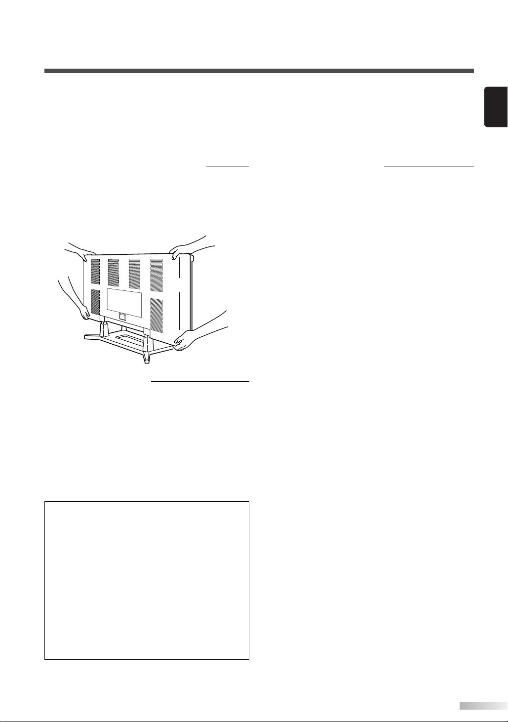
When moving the plasma display
Due to the weight of this plasma display, two people should be used when moving it. Both people
should make sure to grasp the top of the display
with one hand and the base of the display with
the other hand, as in the following illustration.
Optional Accessories
To mount the plasma display on a wall, the following accessory is available:
VISIONMOUNT™ Flat Panel TV Wall Mount from
SANUS SYSTEMS, for large flat panel televisions
(32” to 60”). Refer to page 21 for mounting the
plasma display.
Regarding This Manual
• Product and company names appearing within
this manual are trademarks or registered trademarks of their respective owners.
• Although special care has been taken to ensure
that all information contained within this manual
is correct at time of writing, the information is
subject to change without notice.
• Make sure to read the manual carefully and follow all instructions contained within. We will not
be held responsible for any damages caused by
improper use or handling of this product.
• Reproducing this manual by any means, in
whole or in part, is prohibited.
NOTE:
The wall mounts are not supplied with the plasma display.
#
CAUTION
• This PDP F42PDME is for use only with the
Sanus Systems Model VMPL. Wall Mount.
Use with other wall mounts is capable of
resulting in instability, causing possible injury.
• When mounting the plasma display with the
Sanus Systems wall mount, make sure to
mount it on the wood studs inside the wall, as
failure to do so may result in instability, causing possible injury.
• Refer to the instruction manual included with
the wall mount for details when securing the
plasma display to the wall.
3
Page 6

ONTENTS
C
IMPORTANT SAFETY INSTRUCTIONS . . . . . . . . . . . . . . . . . . . . . . . . . . . . . . .2
SUPPLIED ACCESSORIES . . . . . . . . . . . . . . . . . . . . . . . . . . . . . . . . . . . . . . . .5
INSERTING THE REMOTE CONTROL BATTERIES . . . . . . . . . . . . . . . . . . . . . .5
REMOTE CONTROL RANGE . . . . . . . . . . . . . . . . . . . . . . . . . . . . . . . . . . . . . . .5
COMPONENT NAMES . . . . . . . . . . . . . . . . . . . . . . . . . . . . . . . . . . . . . . . . . . . .6
MAIN UNIT . . . . . . . . . . . . . . . . . . . . . . . . . . . . . . . . . . . . . . . . . . . . . . . . . . . . . . . . .6
REMOTE CONTROL . . . . . . . . . . . . . . . . . . . . . . . . . . . . . . . . . . . . . . . . . . . . . . . . . .7
OPERATING THE PLASMA DISPLAY . . . . . . . . . . . . . . . . . . . . . . . . . . . . . . . .8
BASIC OPERATIONS . . . . . . . . . . . . . . . . . . . . . . . . . . . . . . . . . . . . . . . . . . . . . . . . .8
SELECTING THE INPUT SIGNAL . . . . . . . . . . . . . . . . . . . . . . . . . . . . . . . . . . . . . . . .9
CHANGING THE ASPECT RATIO (SCREEN MODE) . . . . . . . . . . . . . . . . . . . . . . . . .10
STILL . . . . . . . . . . . . . . . . . . . . . . . . . . . . . . . . . . . . . . . . . . . . . . . . . . . . . . . . . . . . .11
SLEEP . . . . . . . . . . . . . . . . . . . . . . . . . . . . . . . . . . . . . . . . . . . . . . . . . . . . . . . . . . . .11
NAVIGATING THE SET UP MENU . . . . . . . . . . . . . . . . . . . . . . . . . . . . . . . . . . . . . . .12
Layout of the Setup Menu . . . . . . . . . . . . . . . . . . . . . . . . . . . . . . . . . . . . . . . . . . .12
ENTERING THE MAIN MENU . . . . . . . . . . . . . . . . . . . . . . . . . . . . . . . . . . . . . . . . . .13
PICTURE SELECT . . . . . . . . . . . . . . . . . . . . . . . . . . . . . . . . . . . . . . . . . . . . . . . . . .13
Automatically Adjusting the Picture Settings . . . . . . . . . . . . . . . . . . . . . . . . . . . . .14
Manually Adjusting the Picture Settings . . . . . . . . . . . . . . . . . . . . . . . . . . . . . . . .14
Initializing the Adjustments . . . . . . . . . . . . . . . . . . . . . . . . . . . . . . . . . . . . . . . . . .14
WINDOW SETTING . . . . . . . . . . . . . . . . . . . . . . . . . . . . . . . . . . . . . . . . . . . . . . . . . .15
SWITCHING THE DISPLAY LANGUAGE . . . . . . . . . . . . . . . . . . . . . . . . . . . . . . . . . .15
SETTING THE SCREEN SAVER AND THE BACKGROUND COLOR . . . . . . . . . . . . .16
Setting the Screen Saver . . . . . . . . . . . . . . . . . . . . . . . . . . . . . . . . . . . . . . . . . . .16
Setting the Background Color . . . . . . . . . . . . . . . . . . . . . . . . . . . . . . . . . . . . . . . .16
EXTERNAL INPUT TERMINALS . . . . . . . . . . . . . . . . . . . . . . . . . . . . . . . . . . . .17
CONNECTING DEVICES TO THE AV INPUT TERMINALS . . . . . . . . . . . . . . . . . . . .18
VIDEO Signal Connection (Basic Signal Transfer) . . . . . . . . . . . . . . . . . . . . . . . . .18
S-VIDEO Signal Connection (Better Signal Transfer) . . . . . . . . . . . . . . . . . . . . . . .18
CONNECTING DEVICES TO THE COMPONENT INPUT TERMINALS . . . . . . . . . . .19
Component 1 Signal (Y, Cb, Cr) Connection (Best Signal Transfer) . . . . . . . . . . . .19
Component 2 Signal (Y, Pb, Pr) Connection (Best Signal Transfer) . . . . . . . . . . . .19
CONNECTING PLASMA DISPLAY TO AUDIO SYSTEM . . . . . . . . . . . . . . . . . . . . . .20
AUDIO Signal Connection . . . . . . . . . . . . . . . . . . . . . . . . . . . . . . . . . . . . . . . . . . .20
CONNECTING THE POWER CABLE . . . . . . . . . . . . . . . . . . . . . . . . . . . . . . . .20
ATTACHING A WALL MOUNT BRACKET (SOLD SEPARATELY) . . . . . . . . . .21
MAINTENANCE . . . . . . . . . . . . . . . . . . . . . . . . . . . . . . . . . . . . . . . . . . . . . . . .22
CLEANING THE PLASMA DISPLAY . . . . . . . . . . . . . . . . . . . . . . . . . . . . . . . . . . . . .22
WARNING . . . . . . . . . . . . . . . . . . . . . . . . . . . . . . . . . . . . . . . . . . . . . . . . . . . .22
TROUBLESHOOTING GUIDE . . . . . . . . . . . . . . . . . . . . . . . . . . . . . . . . . . . . .23
SPECIFICATIONS . . . . . . . . . . . . . . . . . . . . . . . . . . . . . . . . . . . . . . . . . . . . . . .25
FUNAI CORPORATION LIMITED WARRANTY . . . . . . . . . . . . . . . . . . . . . . . . .26
4
Page 7
UPPLIED ACCESSORIES
With in 30 degrees
With in 30 degrees
Approximately
7.6 yds (7 m)
Approximately 5.5 yds (5 m)
Approximately 5.5 yds (5 m)
POWER
INPUT SELECT
DISPLAY
MENU
PREVIOUS
SLEEP
VOL
MUTE
SCREEN MODE
STILL
S
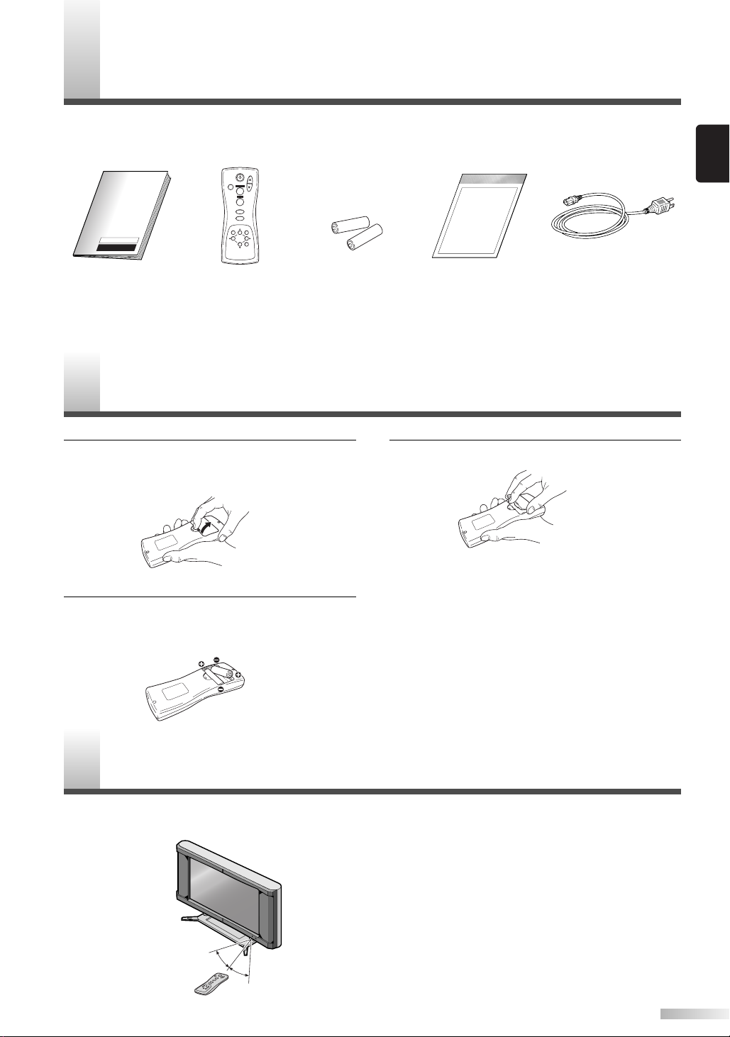
This product comes with the following accessories:
Please confirm that they are included.
English
P Owner's Manual
(1EMN20189)
NOTE:
If any of these accessories are missing, please contact your dealer.
NSERTING THE REMOTE CONTROL BATTERIES
I
1 Remove the back cover of the remote control
P Remote Control
(NE802UD)
P AA batteries x 2 P Power cable
P Set Up Guide
(1EMN20190)
3 Replace the back cover of the remote control.
while pressing the tab on the back cover down
with your finger.
NOTE:
• Do not inser t a mix of old and new batteries.
• Do not inser t a mix of different brands of batteries
2 Insert two AA size batteries, making sure that
the polarities of the batteries match the symbols inside the remote control.
or different types of batteries.
• Always use new, fresh batteries as replacement.
•Never attempt to charge, heat, burn or take apart
batteries.
(WBC0202H0001)
EMOTE CONTROL RANGE
R
Operate the remote control within a 30 degree angle on both sides of the infrared sensor on the main
unit. You can operate the remote control from a distance of several yards away from the main unit.
NOTE:
Other devices which use infrared beams, sunlight,
fluorescent lights, etc., may affect the range and
effectiveness of the remote control. Make sure the
plasma display is positioned in a place which minimizes interference from them.
5
Page 8
OMPONENT NAMES
3
3
S-VIDEO
VIDEO
L
R
S-VIDEOVIDEO
LR
L
R
VIDEO1
S-VIDEO1
VIDEO2
S-VIDEO2
AUDIO
AUDIO OUT
AC IN
AUDIO
Pr
L
Y
Pb
R
Cr
L
Y
Cb
R
COMPONENT1
COMPONENT2
Input Terminals
6 7 8 9
INPUT SELECTVOLUME
POWER
AC IN
S-VIDEO
VIDEO
L
R
L
R
AUDIO
AUDIO OUT
AUDIO
Pr
L
Y
Pb
R
Cr
L
Y
Cb
R
COMPONENT1
COMPONENT2
VIDEO1
S-VIDEO1
VIDEO2
S-VIDEO2
S-VIDEOVIDEO
LR
2
1
4
Infrared Sensor
5
INPUT SELECTVOLUME
POWER
INPUT SELECTVOLUME
C
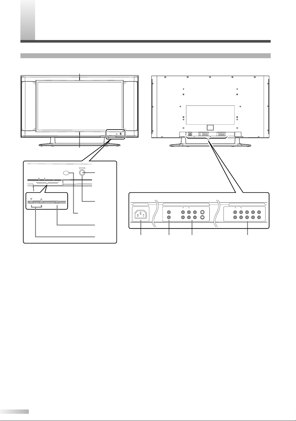
MAIN UNIT
Front Rear
1 POWER button: Tu rns the power ON or in
STANDBY.
2 POWER indicator: Lights up (Blue) when
the power is in the standby mode. Lights up
(Green) when the power is ON.
3 STANDBY indicator: Lights up when the
power is in the standby mode. Disappears
when the power is ON.
4 INPUT SELECT button: Selects input termi-
nals.
5 VOLUME
Increases or decreases the volume.
6 AC IN terminal: Connect the supplied power
cable for a standard AC outlet.
7 AUDIO OUT: Output terminals for audio.
6
K
(up) / L(down) button:
8 AUDIO/VIDEO/S-VIDEO: Input terminals for
an audio and video signal. You can select
either VIDEO or S-VIDEO.
9 COMPONENT: Input terminals for a compo-
nent signal. You can make a Y-Cb-Cr interlaced connection to component 1 or Y-Pb-Pr
progressive or interlaced connection to component 2.
Page 9
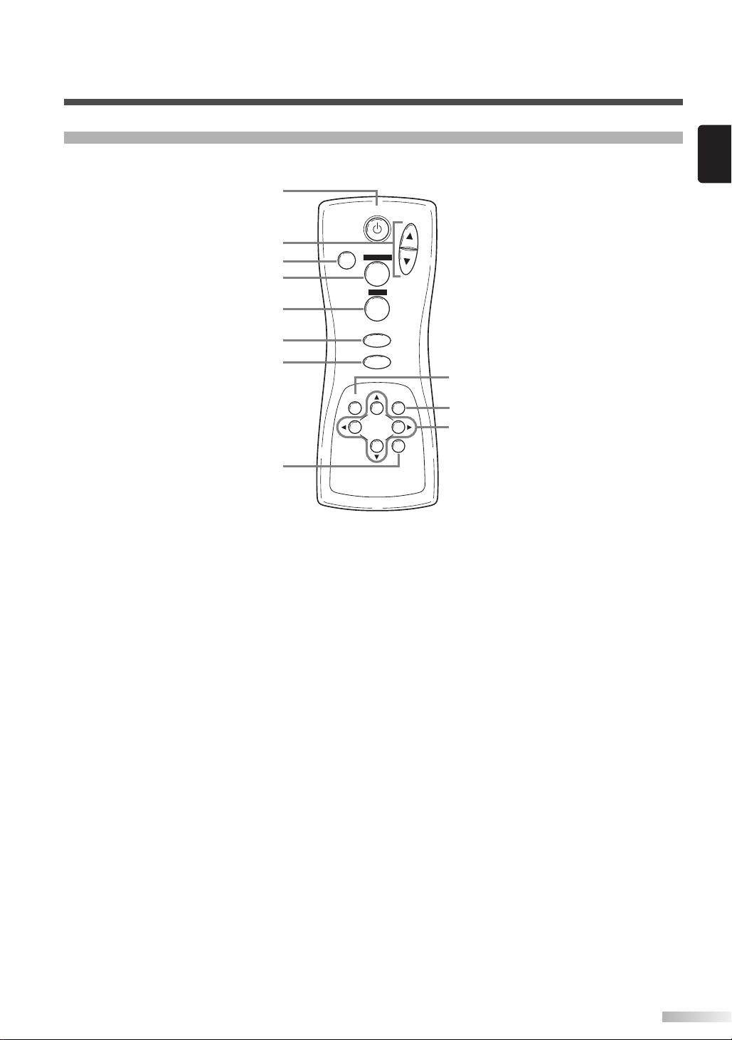
REMOTE CONTROL
POWER
INPUT SELECT
DISPLAY
MENU
PREVIOUS
SLEEP
VOL
MUTE
SCREEN MODE
STILL
1
2
3
4
5
6
7
8
9
10
11
English
1 POWER button: Tu rns the main power ON
or in STANDBY.
2 VOL
K
(up) / L(down) button: Increases or
decreases the volume.
3 MUTE button: Tu r ns the audio off or on.
4 SCREEN MODE button: Selects aspect
ratios available for the screen.
STILL button: Pauses the image shown on
5
the screen.
6 INPUT SELECT button: Selects input termi-
nals.
7 DISPLAY button: Displays the name of the
selected input terminal on the screen.
SLEEP button: Sets the sleep timer.
8
9 MENU button: Accesses the setup menu,
allowing you to access various settings.
10
PREVIOUS button: Moves up one level in
the setup menu.
K
11
(up) / L(down) button: Selects the various
modes in the setup menu.
{(left) / B(right) button: Selects and
adjusts levels for the various settings.
B(enter) button: Also used as the enter
button.
7
Page 10

PERATING THE PLASMA DISPLAY
POWER
INPUT SELECT
DISPLAY
VOL
MUTE
SCREEN MODE
STILL
POWER
INPUT SELECT
O
BASIC OPERATIONS
3 Adjust the volume and screen size according
to your requirements.
Perform adjustments to the volume (VOL K/
button), screen aspect ratio (SCREEN MODE
button) and picture settings (MENU button).
NOTE:
• When you adjust the volume with the VOL K/
button, a message such as the following is displayed on the screen. This message disappears
approximately 4 seconds after performing adjustments.
L
L
The following is a simple explanation of the procedure for turning the power of the display ON or
in STANDBY and the procedure for selecting the
input signal.
The procedure described here is for the remote
control, however the POWER, INPUT SELECT
and VOLUME buttons on the plasma display can
also be used in the same way.
1 Press the POWER button.
Confirm that the STANDBY indicator is lit
before pressing the POWER button.
The power turns ON and the POWER indicator on the main unit turns green. The STANDBY indicator on the main unit disappears.
NOTE:
• It takes approximately 8 seconds for the screen to
display after turning the power ON, but this is not
a malfunction.
Select the input signal by pressing the INPUT
2
SELECT button.
Each time you switch the input, the name of
the selected input terminal is displayed on the
screen for approximately 4 seconds.
NOTE:
• "No signal" is displayed on the screen if there is
no input from the selected terminal and there is
no message currently displayed on the screen for
volume adjustment or the setup menu, etc.
• If there is no video signal and there has been no
operation from the remote control or the buttons
on the main unit for more than 15 minutes, the
auto shut-off function activates and the display
switches to standby mode.
• If you turn the audio mute on, a message slowly
flashes on the screen. At this time, if you press
another button, this flashing stops.
•To turn the audio mute off, either press the MUTE
button again or press the VOLK/Lbutton.
• If you press either the PREVIOUS, K, L, B or {
button in a mode apart from the image adjustment
mode. A message such as the following is displayed.
4 Press the POWER button to turn the power
STANDBY.
The POWER indicator on the main unit turns
blue and the STANDBY indicator lights up.
NOTE:
•You cannot turn the power ON for approximately
3 seconds after the power enters the standby
mode. Do not turn the power to STANDBY and
then ON again in a short time interval.
•Even if the power is turned to STANDBY, the
main unit is in the standby mode. In order to shut
the main power of the display OFF, it is necessary to remove the AC cord from the power outlet.
8
Page 11

POWER
INPUT SELECT
DISPLAY
VOL
MUTE
SCREEN MODE
STILL
INPUT SELECT
DISPLAY
SELECTING THE INPUT SIGNAL
Video 1
(S-Video 1)
Video 2
(S-Video 2)
Component 1
Component 2
The procedure for selecting the input signal
described here is for use with the remote control.
However, the INPUT SELECT button on the plasma display can also be used in the same way.
Displaying the Current Input Signal
Press the DISPLAY button.
1
The name of the current input terminal is displayed on the screen.
2 To clear the name of the current input terminal,
press the DISPLAY button again or wait for
approximately 4 seconds.
NOTE:
•To redisplay the name of the input terminal, press
the DISPLAY button again.
Selecting the Input Signal
1 Press the INPUT SELECT button to select the
input signal.
Each time you switch the input signal, the
name of the selected input terminal is displayed on the display for approximately 4 seconds.
The INPUT SELECT button cycles through the
input terminals in the following pattern:
NOTE:
• When switching the input signal, audio mute turns
ON temporarily.
• S-VIDEO1 takes priority over the VIDEO 1 jack,
as does S-VIDEO 2 over the VIDEO 2 jack.
Therefore, if there is input to the VIDEO and SVIDEO terminals at the same time, the S-VIDEO
signal is displayed on the screen. If the S-VIDEO
cable is not connected to the plasma display, the
VIDEO signal will be displayed on the screen.
• 480i (interlaced) signals can be connected to the
COMPONENT 1 and 2 terminals. Any of the following display formats: 480i, 480p (progressive),
1080i and 720p (progressive) signals can be connected to the COMPONENT 2 terminal. If one of
these video signals is detected, the format of the
input signal is displayed after the name of the
current input terminal, as in the following manner.
English
•A "No signal" message appears if there is no
video signal and there is no message currently
displayed on the screen for volume adjustment or
the setup menu, etc. If there continues to be no
video signal for more than 10 seconds, "No signal" slowly moves around the screen.
• If there is no video signal and there has been no
operation from the remote control or the buttons
on the main unit for more than 15 minutes, the
auto shut-off function activates and the display
switches to standby mode.
9
Page 12

OPERATING THE PLASMA DISPLAY
POWER
INPUT SELECT
DISPLAY
VOL
MUTE
SCREEN MODE
STILL
SCREEN MODE
CHANGING THE ASPECT RATIO (SCREEN MODE)
Each time you change the screen mode, the
name of the selected mode is displayed on the
screen for approximately 4 seconds.
The SCREEN MODE button switches between
the screen modes in the following pattern.
NOTE:
• When switching the input signal, the audio mute
turns ON temporarily.
By changing the aspect ratio of the screen you
can select the manner in which you wish to view
the picture.
•You can only select the "Normal" and "Zoom"
screen modes for 1080i and 720p video signals
connected to the COMPONENT 2 terminal.
1 Press the SCREEN MODE button to display
the current screen mode.
Press the SCREEN MODE button a second
2
time to change the screen mode.
ZoomNormal Full Wide
Mode
Normal
Full
Wide
Zoom
10
Normal
Full
Wide
Zoom
ExplanationPicture
Normal will display a 4:3 picture at its standard 4:3
size. For 1080i and 720p video signals, a picture will
be displayed at 16:9 size.
Full will display a 4:3 picture at a 16:9 size, with
horizontal elongation necessary to fill the screen.
Wide will display a 4:3 picture at a 16:9 size, with less
horizontal elongation necessary to fill the screen
because a little bit of the top and bottom will be cut off.
Zoom will magnify the entire 4:3 picture to fill the
screen, with no horizontal elongation to fill the screen,
as more of the top and bottom are cut off. Use this
mode to view letterboxed 4:3 picture content to get a
widescreen picture. A 16:9 picture will be magnified
similarly, but to a lesser extent.
Page 13
POWER
INPUT SELECT
DISPLAY
VOL
MUTE
SCREEN MODE
STILL
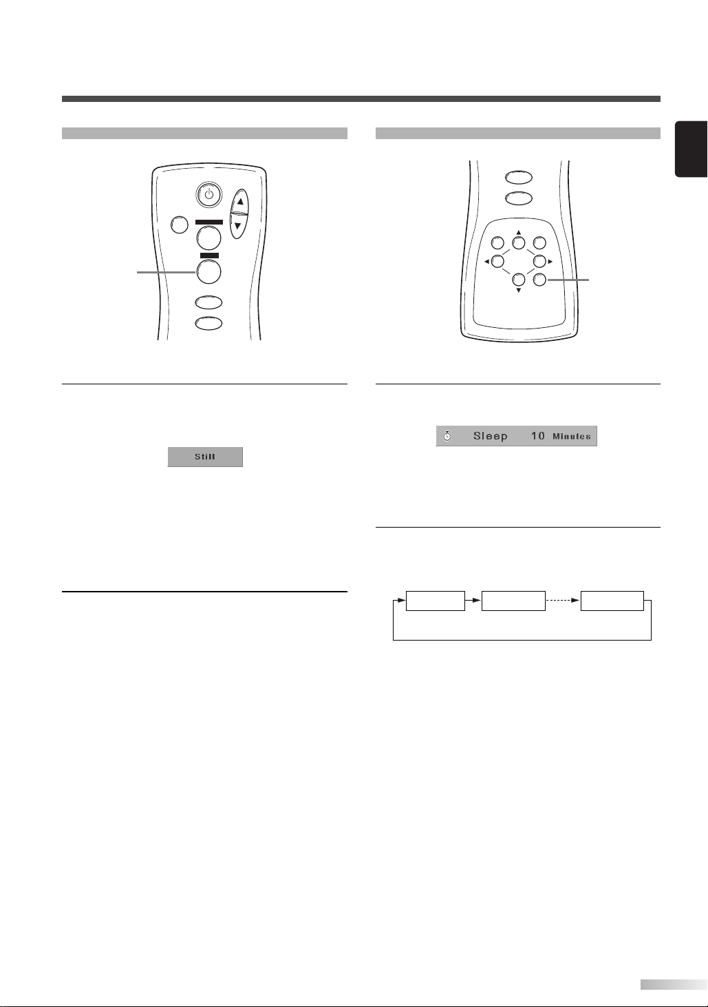
STILL
STILL
INPUT SELECT
DISPLAY
MENU
PREVIOUS
SLEEP
SLEEP
0 minutes 10 minutes 90 minutes
SLEEP
English
To freeze the image on the screen.
Press the STILL button.
1
The still mode turns on and the image displayed on the screen is frozen.
NOTE:
• When the still mode is on, the message "Still"
slowly flashes on the screen.
• When the still mode is on, the audio is muted.
•You cannot turn the still mode on when there is no
video signal or when switching between video signals.
Press the STILL button again to turn the still
2
mode off.
NOTE:
•You can also press the INPUT SELECT,
DISPLAY, SLEEP, VOLK(up) / L(down), MUTE,
SCREEN MODE or MENU buttons to turn the still
mode off.
Selecting sleep timer.
Press the SLEEP button.
1
The sleep timer is displayed on the screen.
NOTE:
• If the sleep timer is activated, the remaining time
is displayed on the screen.
If not activated, “0 minutes” is displayed.
2 Press the SLEEP button to set the time.
The SLEEP button switches between the
times.
The timer starts counting down after the message displaying the set time disappears (after
approximately 4 seconds).
NOTE:
• The remaining time displayed for the sleep timer
changes in steps of 1 minute.
•To change the set time, repeat the above procedure.
11
Page 14
OPERATING THE PLASMA DISPLAY
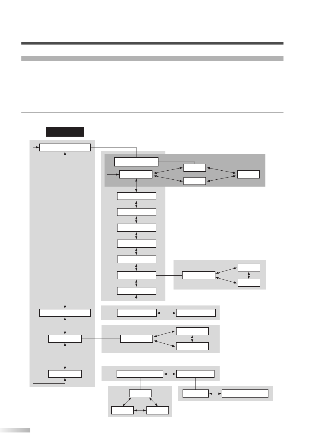
MAIN MENU
Picture select
Picture mode
Window setting H-Position
English
Français
Español
V-Position
Language
Manual
Brightness
Contrast
Color
Tint
Sharpness
Color temp.
Normal
Reset
Dynamic
News
Cool
Warm
Movie
Detail Screen saver Back ground
Opaque Translucent
Fast
Off Slow
NAVIGATING THE SET UP MENU
In the setup menu, you can specify settings for picture adjustment, picture position, language, screen
saver and background.
NOTE:
• If you do not press any buttons for approximately 20 seconds, the display automatically exits the menu mode.
•We recommend to set to the initialized setting of “Manual” in the picture mode.
Layout of the Setup Menu
The various functions in the setup menu are outlined below:
12
Page 15

INPUT SELECT
DISPLAY
MENU
PREVIOUS
SLEEP
MENU
ENTERING THE MAIN MENU
INPUT SELECT
DISPLAY
MENU
PREVIOUS
SLEEP
MENU
B
PREVIOUS
K
L
PICTURE SELECT
English
Press the MENU button.
1
The display enters the main menu and the
MAIN MENU is displayed on the screen.
NOTE:
• If you press the PREVIOUS button or the MENU
button on the MAIN MENU, the menu is cancelled.
•To select a setting, use the B button.
1 Enter the main menu with the MENU button.
“Picture select” is selected on the MAIN
MENU.
Press the B button to select.
2
The PICTURE SELECT menu is displayed on
the screen.
NOTE:
• Press the PREVIOUS button to return to the MAIN
MENU. Pressing the MENU button cancels the
menu.
• Picture select display will disappear from the TV
screen automatically after about 20 seconds if you
do not press any buttons.
13
Page 16

OPERATING THE PLASMA DISPLAY
INPUT SELECT
DISPLAY
MENU
PREVIOUS
SLEEP
MENU
B{
PREVIOUS
K
L
Automatically Adjusting the Picture
Settings
Manually Adjusting the Picture Settings
1 Select "Picture mode" on the PICTURE
SELECT screen with the K/ Lbuttons.
Select "Manual" with the { / B buttons.
2
The display enters the manual mode and you
can specify individual adjustments.
Select the mode to adjust with the K/ Lbut-
3
tons.
The modes rotate in the following order:
"Picture mode" - "Brightness" - "Contrast" - ..
...- "Reset" - "Picture mode"
1 Select "Picture mode" on the PICTURE
SELECT screen with the K/ Lbuttons.
2 Select the automatic adjustment mode accord-
ing to the type of picture displayed on the
screen with the { / B buttons.
NOTE:
• There are 3 modes for automatically adjusting the
picture settings; "News", "Movie" and "Dynamic".
Press the PREVIOUS button to return to the
3
MAIN MENU.
NOTE:
• Pressing the MENU button cancels the menu.
4 Adjust the selected mode using the { / B but-
tons.
NOTE:
• If you have selected Brightness, Contrast, Color,
Tint or Sharpness, the menu display disappears,
and a bar for adjusting the selected mode
appears in the center of the bottom of the screen.
•You can select "Color temp." from among three
modes: "Normal", "Warm" and "Cool".
• If you select "Reset" and press the B button, the
adjusted values return to their initial settings.
To adjust a different mode, repeat steps 3 and 4.
5
6 Press the PREVIOUS button to return to the
Picture mode.
NOTE:
• Pressing the MENU button cancels the menu.
Initializing the Adjustments
Select "Reset" on the PICTURE SELECT
1
screen with the K/ Lbuttons.
2 Press the B button.
The settings you specified individually are initialized.
NOTE:
• The initialized setting of "Manual" are as follows:
BRIGHTNESS: 50/100
CONTRAST: 70/100
COLOR: 50/100
TINT: 50/100
SHARPNESS: 1/2
COLOR TEMP.: Normal
14
Page 17

INPUT SELECT
DISPLAY
MENU
PREVIOUS
SLEEP
B{
K
L
MENU
WINDOW SETTING
INPUT SELECT
DISPLAY
MENU
PREVIOUS
SLEEP
B{
PREVIOUSMENU
K
L
You can move the picture displayed on the screen
up, down, left or right.
Enter the main menu with the MENU button.
1
2 Select "Window setting" on the MAIN MENU
screen with the K/ Lbuttons.
If there is no input from a video signal, "Window
setting" is grayed out and you cannot select it.
4 Select the mode to adjust with the
K/ L
but-
ton.
Select "H-Position" to move the picture horizontally (left or right) and select "V-Position" to
move the screen vertically (up or down).
Adjust with the { / B buttons.
5
The { / B buttons are also used for moving
the picture vertically.
Press the PREVIOUS button to return to the
6
MAIN MENU.
NOTE:
• Pressing the MENU button cancels the menu.
SWITCHING THE DISPLAY LANGUAGE
English
3 Press the B button.
The "WINDOW SETTING" menu is displayed
on the screen.
You can select the language displayed on the
screen from English, French and Spanish.
Enter the main menu with the MENU button.
1
2 Select "Language" on the MAIN MENU screen
with the K/ Lbuttons.
3 Select the language with the { / B buttons.
Press the PREVIOUS button to return to the
4
MAIN MENU.
NOTE:
• Pressing the MENU button cancels the menu.
15
Page 18

OPERATING THE PLASMA DISPLAY
SETTING THE SCREEN SAVER AND THE BACKGROUND COLOR
INPUT SELECT
DISPLAY
K
MENU
PREVIOUS
PREVIOUSMENU
SLEEP
B{
L
You can specify settings for the screen saver and
the background color.
Enter the main menu with the MENU button.
1
2 Select "Detail" on the MAIN MENU screen
with the K/ Lbuttons.
3 Press the B button.
The "DETAIL" menu is displayed on the
screen.
Setting the Screen Saver
1 Select "Screen saver" on the DETAIL screen
with the K/ Lbuttons.
2 Select the mode with the { / B buttons.
NOTE:
• There are 3 modes for the screen saver; "Off",
"Slow" and "Fast".
"Slow" moves 1 pixel every 30 minutes and "Fast"
moves 1 pixel every 10 minutes. This prevents
images burning into the screen.
• When a 480i or 1080i input signal connected to
the COMPONENT 2 terminal is displayed, the vertical movement is different.
"Slow" moves 2 pixels every 60 minutes and
"Fast" moves 2 pixels every 20 minutes.
3 Press the PREVIOUS button to return to the
MAIN MENU screen.
NOTE:
• Pressing the MENU button cancels the menu.
Setting the Background Color
1 Select "Background" on the DETAIL screen
with the K/ Lbuttons.
16
NOTE:
• Press the PREVIOUS button to return to the
MAIN MENU. Pressing the MENU button cancels
the menu.
Select the mode with the { / B buttons.
2
Select "Opaque" or "Translucent" for the background color.
Press the PREVIOUS button to return to the
3
MAIN MENU screen.
NOTE:
• Pressing the MENU button cancels the menu.
Page 19

XTERNAL INPUT TERMINALS
AC IN
S-VIDEO
VIDEO
L
R
S-VIDEO
VIDEO
L
R
L
R
AUDIO
AUDIO OUT
AUDIO
Pr
L
Y
Pb
R
Cr
L
Y
Cb
R
COMPONENT1
COMPONENT2
S-VIDEO
VIDEO
L
R
S-VIDEO
VIDEO
L
R
L
R
AUDIO
AUDIO OUT
AUDIO
Pr
L
Y
Pb
R
Cr
L
Y
Cb
R
COMPONENT1
COMPONENT2
VIDEO1
S-VIDEO1
VIDEO2
S-VIDEO2
VIDEO1
S-VIDEO1
VIDEO2
S-VIDEO2
AV Input Terminals
VIDEO 1, S-VIDEO1
VIDEO 2, S-VIDEO2
See page 18.
Audio Output Terminals
AUDIO OUT
See page 20.
Component Input Terminals
COMPONENT 1
COMPONENT 2
See page 19.
E
The following input terminals are available.
In order to view television, it is necessary to connect a tuner device (example: cable box, satellite box,
DTV, etc.) to the plasma display.
English
17
Page 20
AUDIO
S-VIDEO
2×RCA
audio cables
S-VIDEO
cable
(DVD Player)
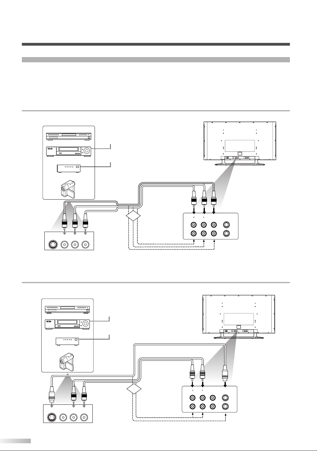
Example of input signal source
(VCR)
(Cable/Sat STB)
(Camcorder)
Antenna or
cable signal
Antenna, cable,
satellite signal
Audio
OUT
Video
OUT
S Video
OUT
LR
Audio input to
L/R sockets
Video input to
S-VIDEO socket
AC IN
S-VIDEO
VIDEO
L
R
L
R
AUDIO
AUDIO OUT
AUDIO
Pr
LY
Pb
R
Cr
LY
Cb
R
COMPONENT1
COMPONENT2
VIDEO1
S-VIDEO1
VIDEO2
S-VIDEO2
S-VIDEOVIDEO
LR
S-VIDEO
VIDEO
L
R
S-VIDEOVIDEO
LR
AUDIO
VIDEO1
S-VIDEO1
VIDEO2
S-VIDEO2
OR
AC IN
S-VIDEO
VIDEO
L
R
L
R
AUDIO
AUDIO OUT
AUDIO
Pr
L
Y
Pb
R
Cr
L
Y
Cb
R
COMPONENT1
COMPONENT2
VIDEO1
S-VIDEO1
VIDEO2
S-VIDEO2
S-VIDEOVIDEO
LR
S-VIDEO
VIDEO
L
R
S-VIDEOVIDEO
LR
AUDIO
VIDEO1
S-VIDEO1
VIDEO2
S-VIDEO2
AUDIO-VIDEO
3×RCA audio
video cables
Video input to
RCA socket
Audio input to
L/R sockets
Audio
OUT
Video
OUT
S Video
OUT
LR
(DVD Player)
Antenna or
cable signal
Antenna, cable,
satellite signal
Example of input signal source
(VCR)
(Cable/Sat STB)
(Camcorder)
OR
EXTERNAL INPUT TERMINALS
CONNECTING DEVICES TO THE AV INPUT TERMINALS
Connect the output of the device to the input terminals of plasma display as shown in the following illustrations.
NOTE:
•You will select TV channels with the VCRs or Cable/Satellite set top box that will be viewed on the plasma display.
• Cables shown here are not included with the plasma display.
VIDEO Signal Connection (Basic Signal Transfer)
S-VIDEO Signal Connection (Better Signal Transfer)
18
Page 21

CONNECTING DEVICES TO THE COMPONENT INPUT TERMINALS
AUDIO
2×RCA
audio cables
R
3×RCA
video cables
(Example: DVD Player)
Y, Cb, Cr
L Y CBC
R
AC IN
S-VIDEO
VIDEO
L
R
L
R
AUDIO
AUDIO OUT
AUDIO
Pr
L
Y
Pb
R
Cr
L
Y
Cb
R
COMPONENT1
COMPONENT2
VIDEO1
S-VIDEO1
VIDEO2
S-VIDEO2
S-VIDEOVIDEO
LR
AUDIO
Pr
L
Y
Pb
R
Cr
L
Y
Cb
R
COMPONENT1
COMPONENT2
Antenna, cable,
satellite signal
PrPbY
2×RCA audio cables
3×RCA video cables
(Example:
Set Top Box for DTV)
AUDIO
R L Y PBP
R
AUDIO
Pr
L
Y
Pb
R
Cr
L
Y
Cb
R
COMPONENT1
COMPONENT2
AC IN
S-VIDEO1
VIDEO1
L
R
L
R
AUDIO
AUDIO OUT
AUDIO
Pr
L
Y
Pb
R
Cr
L
Y
Cb
R
COMPONENT1
COMPONENT2
VIDEO1
S-VIDEO1
VIDEO2
S-VIDEO2
S-VIDEOVIDEO
LR
Connect the output of the device to the input terminals of the plasma display as shown in the following
illustrations.
NOTE:
• When connecting a 480i input signal, connect it to COMPONENT 1.
• Cables shown here are not included with the plasma display.
•You can use COMPONENT 2 for 480i, 1080i (interlaced), 480p, 720p (progressive) video signals.
Component 1 Signal (Y, Cb, Cr) Connection (Best Signal Transfer)
480i (interlaced) signals can be connected to Component 1.
English
Component 2 Signal (Y, Pb, Pr) Connection (Best Signal Transfer)
480i, 480p (progressive), 1080i and 720p (progressive) signals can be connected to Component 2.
NOTE:
You will select TV channels with the box that will be seen on the plasma display.
19
Page 22

AUDIO
2´RCA
audio cables
R
L
TV
AUDIO IN
VIDEO AUX
(Example: Amplifier/Receiver)
Audio output
to L/R sockets
L
R
AUDIO OUT
AC IN
S-VIDEO1
VIDEO1
L
R
L
R
AUDIO
AUDIO OUT
AUDIO
Pr
L
Y
Pb
R
Cr
L
Y
Cb
R
COMPONENT1
COMPONENT2
VIDEO1
S-VIDEO1
VIDEO2
S-VIDEO2
S-VIDEOVIDEO
LR
EXTERNAL INPUT TERMINALS
CONNECTING PLASMA DISPLAY TO AUDIO SYSTEM
NOTE:
Cables shown here are not included with the plasma display.
AUDIO Signal Connection
Connect the AUDIO OUT from the plasma display to the AUDIO IN on the amplifier/receiver.
ONNECTING THE POWER CABLE
C
Connect the power cable to the plasma display after connecting the input terminals.
AUDIO
AUDIO
AC IN
L
R
AUDIO OUT
S-VIDEO1
VIDEO1
Cr
Cb
Y
L
R
VIDEO1
L
COMPONENT1
S-VIDEO1
VIDEO2
R
COMPONENT2
S-VIDEO2
Pr
Pb
Y
L
R
S-VIDEOVIDEO
LR
AC IN
1
#
Connect the power cable to the plasma display
1
first.
Connect the power cable to an AC outlet.
2
20
CAUTION
• Do not connect the power cable to a power
supply outside the indicated voltage of the
plasma display (AC 120V). Connecting the
power cable to a power supply outside of this
range may result in fire or electrical shocks.
• Always use the power cable included with the
plasma display. Do not use any other cable.
For safety, make sure to always connect the
power cable to a three pronged AC outlet.
2
Page 23
2
1
TTACHING A WALL MOUNT BRACKET
AC IN
S-VIDEO
VIDEO
L
R
S-VIDEOVIDEO
LR
L
R
AUDIO
AUDIO OUT
AUDIO
Pr
L
Y
Pb
R
Cr
L
Y
Cb
R
COMPONENT1
COMPONENT2
VIDEO1
S-VIDEO1
VIDEO2
S-VIDEO2
2
Stand
Plasma Display rear
1 1
2
A
(SOLD SEPARATELY)
The following is a description of the method for attaching a wall mount to the plasma display.
When performing this operation, refer to the instruction manual included with the wall mount
kit.
#
CAUTION
•Any damage caused by incorrectly attempting to mount the plasma display is not covered under the
terms of the manufacturers warranty.
English
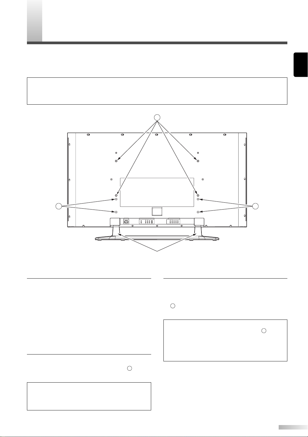
1 Tu rn the plasma display over and place it
screen-first onto a table which has a soft cloth
draped over it.
Place the plasma display in a way so that the
stands hang over the edge of the table.
NOTE:
• Make sure to use a table which can support the
weight of the plasma display and is larger than the
plasma display.
• Make sure the table is in a stable location.
2 Remove the stands from the plasma display.
Unscrew the M5 screws indicated by and
remove the left and right stands.
NOTE:
• The screws and stands you have removed are
necessary for reattachment at a later date. Make
3 Attach the left and right TV rails to the plasma
display using the M8 screws included with the
wall mount kit.
indicates the position of the screw holes on
the plasma display
NOTE:
• Only use the screw holes indicated by for
mounting the plasma display.
•For instructions on how to attach the TV rails,
refer to the instruction manual included with the
mount wall kit.
Attach the plasma display to the wall.
4
NOTE:
• Refer to the instruction manual included with the
wall mount when securing the plasma display to
the wall.
sure to keep them in a safe place.
21
Page 24

AINTENANCE
M
CLEANING THE PLASMA DISPLAY
Always unplug the plasma display from the AC
outlet before cleaning.
Clean the case of the plasma display with a soft
cloth which has been wet and wrung dry.
If the screen of the plasma display is dirty or
dusty, wipe it clean with a soft cloth.
ARNING
W
NOTE:
Never use a solvent, alcohol or any other abrasive liquid to clean the plasma display.
Always make sure the area around vents on the plasma display is clear and clean. Failure to do this may
result in fire or cause the plasma display to fail prematurely.
Preventing Image Burn on the plasma display
Fixed images displayed on the plasma display for an extended period of several hours may cause
uneven pixel aging causing damage to the plasma display. The screensaver mode helps reduce this
phenomenon, but in general you should try to avoid displaying fixed images for extended periods on
the plasma display.
Images of high luminance displayed on the plasma display for more than 60 seconds may cause lingering images to remain on the screen. These images will automatically disappear, but may take
time depending on the luminance of the images and how long they were displayed on the screen.
22
Page 25
ROUBLESHOOTING GUIDE
T
•IGNITION NOISE:
Black spots or horizontal streaks may appear, picture may flutter or drift.
Usually caused by interference from automobile ignition systems, neon
lamps, electrical drills and other electrical appliances.
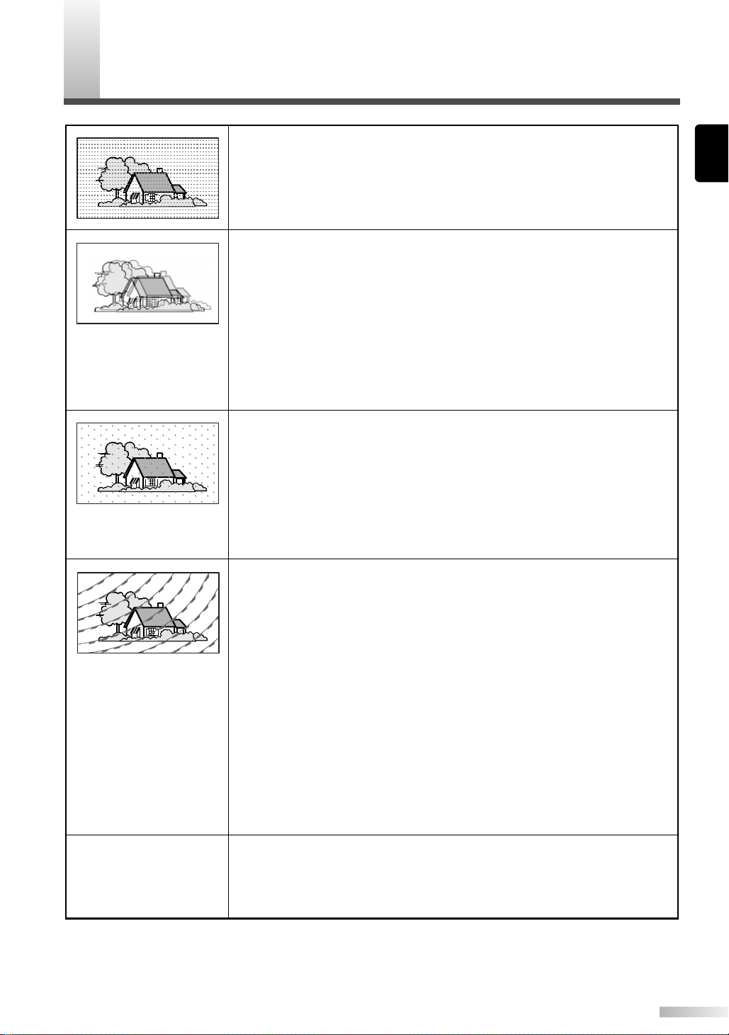
•GHOSTS:
Ghosts are caused by the television signal following two paths. One is the
direct path and the other is reflected from tall buildings, hills or some
other objects. Changing the direction or position of the antenna may
improve reception. Ghosting may also be caused by defects in the
antenna system such as unshielded leads or connecting several sets to
the same antenna without using multiple antenna couplers.
Ghosting occurring when the plasma display is connected to a cable TV
system may indicate a bad cable wire or loose connection. Confirm that
the cable wire is properly connected.
•SNOW:
If your receiver is located in the fringe area of a television station where
the signal is weak, your picture may be marred by the appearance of
small dots. When the signal is extremely weak, it may be necessary to
install a special antenna to improve the picture.
Snowing occurring when the plasma display is connected to a cable TV
system may indicate a bad cable wire or loose connection. Confirm that
the cable wire is properly connected.
English
Vertical stripes appear,
depending on the screen
contents.
•RADIO FREQUENCY INTERFERENCE:
The interference produces moving ripples or diagonal streaks and in
some cases, causes loss of contrast in the picture.
•PREVENTION OF AN OBSTACLE TO RADIO RECEIVERS:
This monitor has been designed pursuant to the FCC class B Rules. This
is to prevent a problem to Radio receivers. lf this monitor causes a
problem to Radio receivers, then take the following steps:
-Keep the monitor away from Radio.
-Adjust Radio antennas in order for the monitor not to receive
interference.
-The antenna cable of Radio should be kept away from the monitor.
-Use a coaxial cable for antenna.
You can check if this monitor influences Radio receivers by turning off all
other equipment other than the monitor.
If you find a problem receiving Radio when using the monitor, check the
instructions mentioned above.
•The plasma display panel is lighting the phosphors by the discharge of
internal radiation. Depending on the screen contents, in rare cases this
may cause vertical stripes to appear because of failure to light. Please
note that this is not a malfunction.
23
Page 26

TROUBLESHOOTING GUIDE
CHECK THESE ITEMS AND
TRY THESE CORRECTIONS
Be sure external connections are correct.
Be sure power cable is plugged in.
Be sure the Display is power switched “ON”
Check for local interference
Adjust Contrast control
SYMPTOM
Remote control does not work
No picture, no sound
Sound OK, picture poor
Picture OK, sound poor
Picture blurred
Weak Picture
Lines or streaks in picture
Picture rolls vertically
No color
Poor picture
Irregular dots on the screen
Adjust Bright control
Adjust Color control
Adjust Tint control
Adjust Volume control
Check batteries in Remote control
It is a characteristic of a Plasma Display.
About Interference to Infrared Devices
Please note in advance that using other infrared devices (such as infrared cordless headphones)
near the plasma display may cause infrared interference to occur.
About Pixel Defects
A plasma display is created by using a collection of miniature pixels. It is possible to display more
than 99.99% of valid pixels, however a small fraction of pixels over the life of the product may not
illuminate or may constantly be illuminated.
This is not to be considered a defect in the plasma display.
24
Page 27

PECIFICATIONS
S
Display Features
Type Plasma panel
Screen Size 42 in. Wide VGA panel
Pixel Resolution 852 (H) x 480 (V)
Output Colors 16.7 million
Screen Aspect Ratio 16:9
Viewing Angle 160 degrees
Contrast Ratio 1000:1
Brightness 470 cd/m2(PEAK)
Comb Filter Type 3-Dimensional Y/C Separation
Available Input Format 720p/1080i/480p/480i (720p/1080i/480p: Component 2 only)
Audio Features
Sound Output 5W + 5W, 10% THD
Speaker Round Type (77mm in diameter) x 4
Additional Features
Screen Saver Off/Slow/Fast
Tr ilingual OSD English/Spanish/French
Color Temperature Select Cool/Normal/Warm
AV Memory Dynamic/Manual/News/Movie
Widescreen Modes 4:3 Standard, Full, Wide, Zoom
Sleep Timer 90 minutes
Wall Mount Kit Ready For VMPLs, SANUS SYSTEMS
English
Connectors
Component AV Input (1) SD component video/Y, Cb, Cr (RCA x 3) - rear
audio L/R (RCA x 2) - rear
Component AV Input (2) HD component video/Y, Pb, Pr (RCA x 3) - rear
audio L/R (RCA x 2) - rear
Composite AV Input (1) Composite video ( RCA x 1 ) - rear
S-Video (1) S-Video (4 pin DIN ) - rear
audio L/R (RCA x 2) - rear
Composite AV Input (2) Composite video ( RCA x 1 ) - rear
S-Video (2) S-Video (4 pin DIN ) - rear
audio L/R (RCA x 2) - rear
Analog Audio output audio L/R (RCA x 2) - rear
General
Power In 120V ±10%, 60Hz/AC
Power Consumption 350 W (Standby: 1.3 W)
Exterior Color Silver & Gray
Dimension
Weight 114.2 lbs (51.8 kg)
(Incl. stand) (Width x Height x Depth)
51 3/4 x 31 5/16 x 15 5/16 in. (1314 x 795 x 389 mm)
NOTE:
The specifications and design of this product are subject to change without notice.
25
Page 28

FUNAI CORPORATION
LIMITED WARRANTY
FUNAI CORP. will repair this product, free of charge in the USA in the event of defect in materials or workmanship as follows:
DURATION:
PARTS: FUNAI CORP. will provide parts to replace defective parts without charge for one (1) year from
LABOR: FUNAI CORP. will provide the labor without charge for a period of ninety (90) days from the
LIMITS AND EXCLUSIONS:
THIS WARRANTY IS EXTENDED ONLY TO THE ORIGINAL RETAIL PURCHASER. A PURCHASE RECEIPT
OR OTHER PROOF OF ORIGINAL RETAIL PURCHASE WILL BE REQUIRED TOGETHER WITH THE PRODUCT TO OBTAIN SERVICE UNDER THIS WARRANTY.
This warranty shall not be extended to any other person or transferee.
This warranty is void and of no effect if any serial numbers on the product are altered, replaced, defaced, missing
or if service was attempted by an unauthorized service center. This FUNAI CORPORATION Limited warranty
does not apply to any the product not purchased and used in the United States.
This warranty only covers failures due to defects in material or workmanship which occurs during normal use. It
does not cover damage which occurs in shipment, or failures which are caused by repairs, alterations or product
not supplied by FUNAI CORP., or damage which results from accident, misuse, abuse, mishandling, misapplication, alteration, faulty installation, improper maintenance, commercial use such as hotel, rental or office use of this
product or damage which results from fire, flood, lightning or other acts of God.
THIS WARRANTY DOES NOT COVER PACKING MATERIALS, ANY ACCESSORIES (EXCEPT REMOTE CONTROL), ANY COSMETIC PARTS, COMPLETE ASSEMBLY PARTS, DEMO OR FLOOR MODELS.
FUNAI CORP. AND ITS REPRESENTATIVES OR AGENTS SHALL IN NO EVENT BE LIABLE FOR ANY GENERAL, INDIRECT OR CONSEQUENTIAL DAMAGES ARISING OUT OF OR OCCASIONED BY THE USE OF
OR THE INABILITY TO USE THIS PRODUCT. THIS WARRANTY IS MADE IN LIEU OF ALL OTHER WARRANTIES, EXPRESS OR IMPLIED, AND OF ALL OTHER LIABILITIES ON THE PART OF FUNAI, ALL OTHER
WARRANTIES INCLUDING THE WARRANTY OF MERCHANTABILITY AND FITNESS FOR A PARTICULAR
PURPOSE, ARE HEREBY DISCLAIMED BY FUNAI AND ITS REPRESENTATIVES IN THE UNITED STATES.
ALL WARRANTY INSPECTIONS ONLY REPAIRS MUST BE PERFORMED BY A FUNAI AUTHORIZED SERVICE CENTER. THIS WARRANTY IS ONLY VALID WHEN THE UNIT IS CARRIED-IN TO A FUNAI AUTHORIZED SERVICE FACILITY.
THE PRODUCT MUST BE ACCOMPANIED BY A COPY OF THE ORIGINAL RETAIL PURCHASE RECEIPT. IF
NO PROOF OF PURCHASE IS ATTACHED, THE WARRANTY WILL NOT BE HONORED AND REPAIRS
COSTS WILL BE CHARGED.
the date of original retail purchase. Three (3) years for Plasma Panel. Certain parts and Plasma
image burn-in are not covered under this warranty.
date of original retail purchase.
IMPORTANT:
THIS LIMITED WARRANTY GIVES YOU SPECIFIC LEGAL RIGHTS. YOU MAY HAVE OTHER RIGHTS THAT VARY
FROM STATE TO STATE. IF, AT ANY TIME DURING THE WARRANTY PERIOD, YOU ARE UNABLE TO OBTAIN SATISFACTION WITH THE REPAIR OF THIS PRODUCT, PLEASE CONTACT FUNAI CORP.
ATTENTION:
FUNAI CORP. RESERVES THE RIGHT TO MODIFY ANY DESIGN OF THIS PRODUCT
WITHOUT PRIOR NOTICE.
To locate your nearest FUNAI CORPORATION Authorized Service Center or general service procedure, please call 1-800-605-8453 or write to the following:
FUNAI CORPORATION, INC.
SERVICE CENTER
19900 Van Ness Avenue, Torrance, CA 90501
Tel :1-800-605-8453
http://www.funai.us
Head Office: 100 North Street, Teterboro, NJ 07608
PLEASE DO NOT SHIP YOUR UNIT TO THE TETERBORO ADDRESS.
26
Page 29

PANTALLA DE PLASMA
Manual del Usuario
F42PDME
Antes de poder ver una imagen en la pantalla de plasma,
deberá conectar primero la unidad a una fuente de vídeo
externa. Consulte la página 18 del manual del usuario.
SI USTED NECESITA ASISTENCIA ADICIONAL PARA LA
INSTALACÌÓN U OPERACIÓN DESPUÉS DE LEER EL
MANUAL DEL USUARIO, POR FAVOR LLAME POR LA
LÍNEA PRE-PAGADA AL: 1-800-605-8453,
O VISITE NUESTRO SITIO WEB EN http://www.funai.us.
Page 30

ADVERTENCIA:
PARA REDUCIR EL RIESGO DE INCENDIOS O DESCARGAS ELÉCTRICAS, NO
EXPONGA ESTE APARATO A LA LLUVIA NI A LA HUMEDAD.
PRECAUCIÓN
RIESGO DE DESCARGA ELÉCTRICA
NO ABRIR
PRECAUCIÓN:
PARA REDUCIR EL RIESGO DE DESCARGA ELÉCTRICA, NO QUITE LA
CUBIERTA (O LA TAPA POSTERIOR). EN EL INTERIOR, NO HAY PIEZAS QUE
EL USUARIO PUEDA REPARAR. CONSULTE AL SERVICIO DE REPARACIONES
PARA OBTENER INFORMACIÓN ACERCA DE PERSONAL CALIFICADO.
ESTE SÍMBOLO INDICA QUE EN ESTA
UNIDAD HAY VOLTAJE PELIGROSO LO
CUAL CONSTITUYE UN RIESGO DE
DESCARGA ELÉCTRICA.
ESTE SÍMBOLO INDICA QUE HAY
INSTRUCCIONES IMPORTANTES DE
FUNCIONAMIENTO Y MANTENIMIENTO
EN LA DOCUMENTACIÓN QUE
ACOMPAÑA AL APARATO.
La nota importante está ubicada en la parte posterior del gabinete.
INSTRUCCIONES DE SEGURIDAD IMPORTANTES
1. Lea estas instrucciones.
2. Guarde estas instrucciones.
3. Preste atención a todas las advertencias.
4. Siga todas las instrucciones.
5. No utilice este aparato cerca del agua.
6. Límpielo sólo con un trapo seco.
7. No bloquee ninguna abertura de ventilación. Instálelo de acuerdo con las instrucciones del fabricante.
8. No lo instale cerca de ninguna fuente de calor como radiadores,
rejillas de calefacción, estufas ni ningún otro aparato (incluyendo
amplificadores) que produzca calor.
9. Por motivos de seguridad, utilice un enchufe de conexión a tierra
o polarizado. El enchufe polarizado tiene dos hojas, una de las
cuales es más ancha que la otra. El enchufe de conexión a tierra
tiene dos hojas y una tercera clavija de conexión a tierra. La hoja
ancha o la tercera clavija están provistas para su seguridad. Si
el enchufe incluido no encaja en su tomacorriente, consulte a un
electricista para que reemplace el tomacorriente obsoleto.
10. Proteja el cable de alimentación para que no lo pisen ni lo aplasten, especialmente en la parte de los enchufes, en los receptáculos y en el punto desde donde sale del aparato.
INTERFERENCIA DE RADIO-TELEVISIÓN
Este equipo fue probado y se comprobó que cumple con los límites para un dispositivo digital Clase B, de acuerdo con la Parte
15 de las normas de la FCC (Comisión Federal de Comunicaciones). Estos límites están diseñados para ofrecer una protección
razonable contra la interferencia perjudicial en una instalación residencial. Este equipo genera, utiliza y puede irradiar energía
de radiofrecuencia y, si no se instala y se utiliza de acuerdo con las instrucciones, puede producir interferencia perjudicial en las
comunicaciones radiales. Sin embargo, no se garantiza que no haya interferencia en una instalación en particular. Si este equipo
sí produce una interferencia perjudicial en la recepción televisiva o radial, lo cual puede estar determinado por el hecho de
encender y apaga el equipo, se alienta al usuario a intentar corregir la interferencia con una o más de las siguientes medidas:
1) Reoriente o reubique la antena receptora.
2) Aumente la distancia entre el equipo y el receptor.
3) Conecte el equipo a un tomacorriente en un circuito diferente del que está conectado el receptor.
4) Consult the dealer or an experienced radio/TV technician for help.
Este aparato digital Clase B cumple con las normas canadienses ICES-003.
ADVERTENCIA DE LA FCC-
Este equipo puede generar o utilizar energía de radiofrecuencia. Los cambios o las modificaciones a este
equipo pueden causar serias interferencias si dichos cambios o modificaciones no han sido expresamente aprobados en el manual de
instrucciones. El usuario podrá perder la autoridad para operar este equipo si efectúa una modificación o cambio no autorizado.
El número de serie de este producto se puede encontrar en la parte posterior de esta unidad. Ninguna otra unidad tiene su
mismo número de serie. Le recomendamos que registre ese número y cualquier otra información vital aquí mismo y conserve
este libro como un registro permanente de su compra para ayudar a identificarla en caso de robo.
Fecha de compra
Empresa vendedora
Dirección de la empresa
11. Utilice sólo los acoples/accesorios especificados por el fabricante.
12. Utilícelo sólo con el carro, el soporte, el trípode o
la mesa especificados por el fabricante o vendidos
con el aparato. Cuando se utiliza un carro, la combinación carro/aparato debe ser movida con cuidado para evitar lesiones causadas por una caída.
13. Desenchufe este aparato durante tormentas eléctricas o cuando no se lo utilice durante períodos de tiempo prolongados.
14. Deje toda la reparación al personal de servicio calificado. Es
necesaria la reparación cuando el aparato se dañó de alguna
manera, por ejemplo, si el cable de alimentación de energía o el
enchufe está dañado, si se derramó líquido o si se cayeron objetos en el aparato, o si el aparato fue expuesto a la lluvia o
humedad, o si no funciona normalmente o si se cayó.
15. No se debe exponer al aparato a goteos ni a salpicaduras y no
se debe colocar sobre el mismo ningún objeto que contenga
líquido, como floreros.
Para reducir el riesgo de incendios o descargas eléctricas, no
exponga este aparato a la lluvia ni a la humedad.
S3125A
Teléfono de la empresa
Modelo No.
Serie No.
2
Page 31

Gracias por comprar esta pantalla de plasma.
Asegúrese de leer este manual antes de utilizar la pantalla de plasma y preste especial atención a las Instrucciones de seguridad incluidas en el mismo.
Cuando haya terminado de leer este manual, guárdelo en un lugar seguro para tener un fácil
acceso en el futuro.
Cuando se mueve la pantalla de plasma
Debido al peso de esta pantalla de plasma, se
necesitan dos personas para moverla. Ambas
personas deben asegurarse de sostener la parte
superior de la pantalla con una mano y la base
de la pantalla con la otra, como en el siguiente
dibujo.
Accesorios opcionales
Para instalar la pantalla de plasma en una pared,
se encuentra disponible el siguiente accesorio:
Soporte de pared para TV de panel plano
VISIONMOUNT™ de SANUS SYSTEMS para
televisores grandes de paneles planos (desde 32”
hasta 60”). Consulte la página 21 para la instalación de la pantalla de plasma.
Con respecto a este manual
• Los nombres de la compañía y del producto que
aparecen en este manual son marcas comerciales o marcas comerciales registradas de sus
respectivos dueños.
•Aunque se tuvo un cuidado especial para garantizar que toda la información incluida en este
manual sea correcta al momento de escribirlo, la
información está sujeta a cambios sin previo
aviso.
• Asegúrese de leer este manual atentamente y
de seguir todas las instrucciones incluidas en el
mismo. No nos haremos responsables de
ningún daño o perjuicio ocasionado por la utilización o el manejo incorrectos de este producto.
• La reproducción total o parcial de este manual
está estrictamente prohibida.
Español
NOTA:
Los soportes de pared no vienen incluidos con la pantalla de plasma.
#
PRECAUCIÓN
• Este PDP F42PDME sólo se puede utilizar
con el soporte de pared VMPL. del modelo
de Sanus Systems. Si se utiliza con otros
soportes de pared, es posible que se produzca inestabilidad, lo que puede causar
lesiones.
• Al instalar la pantalla de plasma con el
soporte de pared Sanus Systems, asegúrese
de instalarlo en las columnas de madera
dentro de la pared, de lo contrario, puede
volverse inestable y causar posibles lesiones.
• Cuando esté fijando la pantalla de plasma en
la pared, consulte el manual de instrucciones
incluido con el soporte de pared por obtener
más detalles.
3
Page 32

ONTENIDOS
C
INSTRUCCIONES DE SEGURIDAD IMPORTANTES . . . . . . . . . . . . . . . . . . . . .2
ACCESORIOS INCLUIDOS . . . . . . . . . . . . . . . . . . . . . . . . . . . . . . . . . . . . . . . .5
INSTALACIÓN DE LAS PILAS DEL CONTROL REMOTO . . . . . . . . . . . . . . . . .5
ALCANCE DEL CONTROL REMOTO . . . . . . . . . . . . . . . . . . . . . . . . . . . . . . . . .5
NOMBRES DE LOS COMPONENTES . . . . . . . . . . . . . . . . . . . . . . . . . . . . . . . .6
UNIDAD PRINCIPAL . . . . . . . . . . . . . . . . . . . . . . . . . . . . . . . . . . . . . . . . . . . . . . . . . .6
CONTROL REMOTO . . . . . . . . . . . . . . . . . . . . . . . . . . . . . . . . . . . . . . . . . . . . . . . . . .7
OPERACIÓN DE LA PANTALLA DE PLASMA . . . . . . . . . . . . . . . . . . . . . . . . . .8
OPERACIONES BÁSICAS . . . . . . . . . . . . . . . . . . . . . . . . . . . . . . . . . . . . . . . . . . . . . .8
SELECCIÓN DE LA SEÑAL DE ENTRADA . . . . . . . . . . . . . . . . . . . . . . . . . . . . . . . . .9
CAMBIO DE LA RELACIÓN DE ASPECTO (MODO DE PANTALLA) . . . . . . . . . . . . .10
Imagen fija . . . . . . . . . . . . . . . . . . . . . . . . . . . . . . . . . . . . . . . . . . . . . . . . . . . . . . . . .11
Reposar . . . . . . . . . . . . . . . . . . . . . . . . . . . . . . . . . . . . . . . . . . . . . . . . . . . . . . . . . . .11
NAVEGACIÓN POR EL MENÚ DE CONFIGURACIÓN . . . . . . . . . . . . . . . . . . . . . . .12
Disposición del menú de configuración . . . . . . . . . . . . . . . . . . . . . . . . . . . . . . . . .12
INGRESO AL MENÚ DE PREPAR. . . . . . . . . . . . . . . . . . . . . . . . . . . . . . . . . . . . . . .13
SELEC DE IMAGEN . . . . . . . . . . . . . . . . . . . . . . . . . . . . . . . . . . . . . . . . . . . . . . . . .13
Ajuste automático de las configuraciones de la imagen . . . . . . . . . . . . . . . . . . . . .14
Ajuste manual de las configuraciones de la imagen . . . . . . . . . . . . . . . . . . . . . . .14
Activación de los ajustes . . . . . . . . . . . . . . . . . . . . . . . . . . . . . . . . . . . . . . . . . . . .14
AJUSTE DE VENTA. . . . . . . . . . . . . . . . . . . . . . . . . . . . . . . . . . . . . . . . . . . . . . . . . .15
CAMBIO DEL IDIOMA DE LA PANTALLA . . . . . . . . . . . . . . . . . . . . . . . . . . . . . . . . .15
AJUSTE DEL PROTECTOR DE PANTALLA Y DEL COLOR DE FONDO . . . . . . . . . .16
Ajuste del protector de pantalla . . . . . . . . . . . . . . . . . . . . . . . . . . . . . . . . . . . . . . .16
Ajuste del color de fondo . . . . . . . . . . . . . . . . . . . . . . . . . . . . . . . . . . . . . . . . . . .16
TERMINALES DE ENTRADA EXTERNA . . . . . . . . . . . . . . . . . . . . . . . . . . . . .17
CONEXIÓN DE LOS DISPOSITIVOS A LAS TERMINALES DE ENTRADA DE
AUDIO/VIDEO . . . . . . . . . . . . . . . . . . . . . . . . . . . . . . . . . . . . . . . . . . . . . . . . . . . . . .18
Conexión de la señal de VIDEO (transferencia básica de la señal) . . . . . . . . . . . .18
Conexión de la señal S-VIDEO (mejor transferencia de la señal) . . . . . . . . . . . . .18
CONEXIÓN DE LOS DISPOSITIVOS A LAS TERMINALES DE ENTRADA DE
COMPONENTE . . . . . . . . . . . . . . . . . . . . . . . . . . . . . . . . . . . . . . . . . . . . . . . . . . . . .19
Conexión de la señal de Component 1 (Y, Cb, Cr)
(mejor transferencia de la señal) . . . . . . . . . . . . . . . . . . . . . . . . . . . . . . . . . . . . . .19
Conexión de la señal de Component 2 (Y, Pb, Pr)
(mejor transferencia de la señal) . . . . . . . . . . . . . . . . . . . . . . . . . . . . . . . . . . . . . .19
CONEXIÓN DE LA PANTALLA DE PLASMA AL SISTEMA DE AUDIO . . . . . . . . . . . .20
Conexión de la señal de AUDIO . . . . . . . . . . . . . . . . . . . . . . . . . . . . . . . . . . . . . .20
CONEXIÓN DEL CABLE DE ALIMENTACIÓN . . . . . . . . . . . . . . . . . . . . . . . . .20
FIJACIÓN DE UN SOPORTE DE PARED (VENDIDO POR SEPARADO) . . . . .21
MANTANIMIENTO . . . . . . . . . . . . . . . . . . . . . . . . . . . . . . . . . . . . . . . . . . . . . .22
LIMPIEZA DE LA PANTALLA DE PLASMA . . . . . . . . . . . . . . . . . . . . . . . . . . . . . . . .22
ADVERTENCIA . . . . . . . . . . . . . . . . . . . . . . . . . . . . . . . . . . . . . . . . . . . . . . . .22
GUÍA EN CASO DE FALLAS . . . . . . . . . . . . . . . . . . . . . . . . . . . . . . . . . . . . . .23
ESPECIFICACIONES . . . . . . . . . . . . . . . . . . . . . . . . . . . . . . . . . . . . . . . . . . . .25
FUNAI CORPORATION GARANTIA LIMITADA . . . . . . . . . . . . . . . . . . . . . . . .26
4
Page 33

CCESORIOS INCLUIDOS
Dentro de los 30 grados
Dentro de los 30 grados
7,6 yardas (7m)
aproximadamente
5,5 yardas (5m) aproximadamente
5,5 yardas (5m) aproximadamente
POWER
INPUT SELECT
DISPLAY
MENU
PREVIOUS
SLEEP
VOL
MUTE
SCREEN MODE
STILL
A
Este producto viene con los siguientes accesorios:
Verifique que estén incluidos.
P
Manual del usuario
(1EMN20189)
NOTA:
Si falta alguno de estos accesorios, contáctese con su distribuidor.
NSTALACIÓN DE LAS PILAS DEL CONTROL REMOTO
I
P Control remoto
(NE802UD)
P Pilas AA x 2 P
P
Guía de instalación
(1EMN20190)
Español
Cable de alimentación
(WBC0202H0001)
1 Quite la tapa posterior del control remoto
mientras presiona la lengüeta de la tapa posterior hacia abajo con su dedo.
2 Inserte dos pilas tamaño AA y asegúrese de
que las polaridades de las pilas coincidan con
los símbolos dentro del control remoto.
LCANCE DEL CONTROL REMOTO
A
Opere el control remoto dentro de un ángulo de 30 grados en ambos lados del sensor infrarrojo de la unidad
principal. Puede operar el control remoto desde una distancia de varias yardas desde la unidad principal.
3 Vuelva a colocar la tapa posterior del control
remoto.
NOTA:
• No mezcle pilas viejas y nuevas.
• No mezcle marcas de pilas diferentes o tipos de
pilas diferentes.
• Utilice siempre pilas nuevas para el reemplazo.
• No intente nunca cargar, calentar, quemar ni
desarmar las pilas.
NOTA:
Otros dispositivos que utilizan rayos infrarrojos,
luz solar, luces fluorescentes, etc. pueden afectar
el alcance y la efectividad del control remoto.
Asegúrese de que la pantalla de plasma esté ubicada en un lugar que minimice la interferencia
que producen.
5
Page 34

OMBRES DE LOS COMPONENTES
3
3
S-VIDEO
VIDEO
L
R
S-VIDEOVIDEO
LR
L
R
VIDEO1
S-VIDEO1
VIDEO2
S-VIDEO2
AUDIO
AUDIO OUT
AC IN
AUDIO
Pr
L
Y
Pb
R
Cr
L
Y
Cb
R
COMPONENT1
COMPONENT2
Terminales de entrada
6 7 8 9
INPUT SELECTVOLUME
POWER
AC IN
S-VIDEO
VIDEO
L
R
L
R
AUDIO
AUDIO OUT
AUDIO
Pr
L
Y
Pb
R
Cr
L
Y
Cb
R
COMPONENT1
COMPONENT2
VIDEO1
S-VIDEO1
VIDEO2
S-VIDEO2
S-VIDEOVIDEO
LR
2
1
4
Sensor infrarrojo
5
INPUT SELECTVOLUME
POWER
INPUT SELECTVOLUME
N
UNIDAD PRINCIPAL
Parte delantera Parte posterior
1 Botón POWER: ENCIENDE (ON) o pone
EN ESPERA (STANDBY).
2 Indicador POWER: Se enciende (azul)
cuando la unidad está en modo de espera.
Se enciende (verde) cuando está
ENCENDIDO (ON).
3 Indicador STANDBY: Se enciende cuando
la unidad está en modo de espera.
Desaparece cuando está
ENCENDIDO (ON).
4 Botón INPUT SELECT: Selecciona las ter-
minales de entrada.
5 Botón VOLUME
Aumenta o disminuye el volumen.
6 Terminal AC IN: Conecte el cable de ali-
mentación incluido a un tomacorriente
estándar de CA (AC).
7 AUDIO OUT: Ter minales de salida para
audio.
6
K
(subir) / L(bajar):
8 AUDIO/VIDEO/S-VIDEO: Te rminales de
entrada para una señal de audio y video.
Puede seleccionar VIDEO o S-VIDEO.
9 COMPONENT: Te r minales de entrada para
la señal de un componente. Puede realizar
una conexión entrelazada Y-Cb-Cr a component 1 o una conexión progresiva o entrelazada Y-Pb-Pr a component 2.
Page 35

CONTROL REMOTO
POWER
INPUT SELECT
DISPLAY
MENU
PREVIOUS
SLEEP
VOL
MUTE
SCREEN MODE
STILL
1
2
3
4
5
6
7
8
9
10
11
Español
1 Botón POWER: ENCIENDE (ON) o pone
EN ESPERA (STANDBY).
2 Botón VOL
disminuye el volumen.
3 Botón MUTE: Apaga el audio o ENCENDI-
DO.
K
(subir) / L(bajar): Aumenta o
4 Botón SCREEN MODE: : Selecciona las
relaciones de aspecto disponibles para la
pantalla.
5 Botón STILL: Detiene la imagen que se
muestra en la pantalla.
6 Botón INPUT SELECT: Selecciona las ter-
minales de entrada.
Botón DISPLAY: Visualiza el nombre de la
7
terminal de entrada seleccionada en la pantalla.
Botón SLEEP: Ajusta el temporizador para
8
dormir.
de configuración y le permite acceder a
diferentes ajustes.
10
Botón PREVIOUS: Sube un nivel en el
menú de configuración.
11
Botón K(subir) / L(bajar): Selecciona
diversos modos en el menú de configuración.
Botón
{ (izquierda) / B (derecha):
Selecciona y ajusta los niveles para diversas
configuraciones.
Botón
B (ingresar) : También se utiliza
como el botón ingresar.
7
9 Botón MENU: Permite el acceso al menú
Page 36

PERACIÓN DE LA PANTALLA DE PLASMA
POWER
INPUT SELECT
DISPLAY
VOL
MUTE
SCREEN MODE
STILL
POWER
INPUT SELECT
O
OPERACIONES BÁSICAS
La siguiente es una simple explicación del procedimiento para encender (ON) o poner en
espera (STANDBY) la unidad y del procedimiento
para seleccionar la señal de entrada.
El procedimiento descrito aquí es para el control
remoto, sin embargo, los botones POWER,
INPUT SELECT y VOLUME en la pantalla de
plasma también se pueden utilizar de la misma
manera.
1 Pulse el botón POWER.
Confirme que el indicador STANDBY esté
encendido antes de presionar el botón
POWER.
enciende (ON) la unidad y el indicador
POWER de la unidad principal cambia a
verde. El indicador STANDBY en la unidad
principal desaparece.
NOTA:
•Tarda 8 segundos aproximadamente para que se
visualice la pantalla luego de encender (ON) la
unidad, pero esto no es un malfuncionamiento.
2 Seleccione la señal de entrada con el botón
INPUT SELECT.
Cada vez que cambia la entrada, se visualiza
el nombre de la terminal de entrada seleccionada en la pantalla durante 4 segundos
aproximadamente.
NOTA:
• Se visualiza “No SeÑal” en la pantalla si no hay
una entrada desde la terminal seleccionada y no
hay ningún mensaje visualizado actualmente en
la pantalla para el ajuste del volumen o del menú
de configuración.
• Si no hay una señal de video y no se operó
desde el control remoto ni desde los botones de
la unidad principal durante más de 15 minutos, la
función de apagado automático se activa y la
pantalla cambia a modo de espera.
8
3 Ajuste el volumen y el tamaño de la pantalla
de acuerdo con sus necesidades.
Realice los ajustes de volumen (botón
VOLK/L), la relación de aspecto de la pan-
talla (botón SCREEN MODE) y los ajustes de
la imagen (botón MENU).
NOTA:
• Cuando ajusta el volumen con el botón
VOL K/L, se visualiza en la pantalla un mensaje
como el siguiente. Este mensaje desaparece 4
segundos aproximadamente después de haber
realizado los ajustes.
• Si enciende el silencio de audio, en la pantalla
destella lentamente un mensaje. En este momento, si pulsa otro botón, este destello se detiene.
•Para apagar el silencio de audio, pulse el botón
MUTE nuevamente o pulse el botón VOLK/L.
• Si pulsa el botón PREVIOUS, K, L, B o { en un
modo que no sea el modo de ajuste de imagen,
se visualiza un mensaje como el siguiente.
4 Pulse el botón POWER para cambiar la unidad
a STANDBY.
El indicador POWER de la unidad principal
cambia a azul y el indicador STANDBY se
enciende.
NOTA:
• No puede encender (ON) la unidad durante 3
segundos aproximadamente luego de que se
ingresa al modo en espera. No cambie la unidad
de en espera (STANDBY) a enciendo (ON)
nuevamente en un periodo corto de tiempo.
•Aun si la unidad está en espera (STANDBY), la
unidad principal está en modo en espera. Para
apagar (OFF) la energía principal de la pantalla,
es necesario quitar el cable de CA (AC) del
tomacorriente.
Page 37

POWER
INPUT SELECT
DISPLAY
VOL
MUTE
SCREEN MODE
STILL
INPUT SELECT
DISPLAY
SELECCIÓN DE LA SEÑAL DE ENTRADA
Aux 1
(Video-S1)
Aux 2
(Video-S2)
Componentes 1
Componentes 2
Selección de la señal de entrada
1 Pulse el botón INPUT SELECT para selec-
El procedimiento para seleccionar la señal de
entrada descrito aquí es para utilizar con el control remoto. Sin embargo, el botón INPUT
SELECT en la pantalla de plasma también se
puede utilizar de la misma manera.
NOTA:
Visualización de la señal de entrada
actual
1 Pulse el botón DISPLAY.
El nombre de la terminal de entrada actual se
visualiza en la pantalla.
2 Para borrar el nombre de la terminal de entra-
da actual, pulse el botón DISPLAY nueva-
mente o espere 4 segundos aproximadamente.
NOTA:
•Para volver a visualizar el nombre de la terminal
de entrada, pulse el botón DISPLAY nuevamente.
cionar la señal de entrada.
Cada vez que cambia la señal de entrada, se
visualiza el nombre de la terminal de entrada
seleccionada en la pantalla durante 4 segundos aproximadamente.
El botón INPUT SELECT realiza un ciclo a
través de las terminales de entrada de esa
manera:
• Cuando cambia la señal de entrada, el silencio
de audio cambia a encendido (ON) temporalmente.
• S-VIDEO1 (Video-S1) tiene prioridad sobre el
enchufe de VIDEO 1 (Aux 1) y S-VIDEO 2
(Video-S2) sobre el enchufe VIDEO 2 (Aux 2).
Por lo tanto, si hay una entrada a las terminales
VIDEO y S-VIDEO al mismo tiempo, se visualiza
la señal S-VIDEO en la pantalla. Si el cable SVIDEO no está conectado a la pantalla de plasma, se visualizará la señal VIDEO en la pantalla.
• Las señales 480i (entrelazadas) se pueden
conectar a las terminales COMPONENT
(Componentes) 1 y 2. Cualquiera de los siguientes formatos de visualización en pantalla: Las
señales 480i, 480p (progresiva), 1080i y 720p
(progresiva) se pueden conectar a la terminal
COMPONENT 2. Si se detecta una de estas
señales de video, el formato de la señal de entrada se visualiza luego del nombre de la terminal
de entrada de video actual de la siguiente manera.
Español
• Si no hay una señal de video y no hay un mensaje actualmente visualizado en la pantalla para
el ajuste de volumen o del menú de configuración, etc., aparece un mensaje “No SeÑal”. Si
la señal de video continúa sin aparecer durante
más de 10 segundos, “No SeÑal” se desplaza
lentamente por la pantalla.
• Si no hay una señal de video y no se operó
desde el control remoto ni desde los botones de
la unidad principal durante más de 15 minutos, la
función de apagado automático se activa y la
pantalla cambia a modo de espera.
9
Page 38

OPERACIÓN DE LA PANTALLA DE PLASMA
POWER
INPUT SELECT
DISPLAY
VOL
MUTE
SCREEN MODE
STILL
SCREEN MODE
ZoomNormal
Pantalla
Completa
Ancha
CAMBIO DE LA RELACIÓN DE ASPECTO (MODO DE PANTALLA)
Cada vez que cambia el modo de pantalla, se
visualiza el modo seleccionado en la pantalla
durante 4 segundos aproximadamente.
El botón SCREEN MODE cambia entre los
modos de pantalla de esta manera.
NOTE:
• Cuando cambia la señal de entrada, el silencio de
Al cambiar la relación de aspecto de la pantalla,
usted puede seleccionar la forma en la que desea
ver la imagen.
audio cambia a encendido (ON) temporalmente.
•You can only select the “Normal” and “Zoom”
screen modes for 1080i and 720p video signals
connected to the COMPONENT 2 terminal.
1 Pulse el botón SCREEN MODE para visualizar
el modo de pantalla actual.
Pulse el botón SCREEN MODE por segunda
2
vez para cambiar el modo de pantalla.
Modo
Normal
Pantalla
Completa
Ancha
10
Zoom
Normal
Pantalla Completa
Ancha
Zoom
ExplicaciónImagen
Normal visualizará una imagen de 4:3 en su tamaño
4:3 estándar. Para las señales de video 1080i y 720p,
se visualizará una imagen de un tamaño de 16:9.
Pantalla Completa visualizará una imagen de 4:3 en un
tamaño de 16:9, con un estiramiento horizontal
necesario para completar la pantalla.
Ancha visualizará una imagen de 4:3 en un tamaño de
16:9, con un estiramiento horizontal menor necesario
para completar la pantalla porque se cortará un poco
de la parte superior e inferior de la imagen.
Zoom aumentará toda la imagen de 4:3 para completar la pantalla,
sin estiramiento horizontal para completar la pantalla mientras que
se corta más de la parte superior e inferior de la imagen. Utilice este
modo para ver el contenido de una imagen de 4:3 en formato buzón
para obtener una imagen del ancho de la pantalla. La imagen de
16:9 se aumentará de manera similar pero en un grado menor.
Page 39

POWER
INPUT SELECT
DISPLAY
VOL
MUTE
SCREEN MODE
STILL
STILL
IMAGEN FIJA
INPUT SELECT
DISPLAY
MENU
PREVIOUS
SLEEP
SLEEP
0 minutos 10 minutos 90 minutos
REPOSAR
Español
Para congelar la imagen en la pantalla.
Pulse el botón STILL.
1
Se enciende el modo fijo y la imagen que se
visualiza en la pantalla se congela.
NOTA:
• Cuando se enciende el modo fijo, el mensaje
“Imagen fija” destella lentamente en la pantalla.
• Cuando el modo fijo está encendido, el audio está
en silencio.
• No puede encender el modo fijo cuando no hay
una señal de video ni cuando cambia entre
señales de video.
Pulse el botón STILL nuevamente para apagar
2
el modo fijo.
NOTA:
•También puede pulsar los botones
INPUT SELECT, DISPLAY, SLEEP,
VOLK(subir) / L(bajar), MUTE, SCREEN MODE
o MENU para apagar el modo fijo.
Seleccione el temporizador para dormir.
Pulse el botón SLEEP.
1
El temporizador para dormir se visualiza en la
pantalla.
NOTA:
• Si el temporizador para dormir está activado, el
tiempo restante se visualiza en la pantalla.
De lo contrario, se visualiza “0 minutos”.
Pulse el botón SLEEP para ajustar la hora.
2
El botón SLEEP cambia entre hora y hora.
El temporizador comienza la cuenta regresiva
después de que el mensaje que visualiza la
hora ajustada desaparece (luego de 4 segundos aproximadamente).
NOTA:
• El tiempo restante visualizado para el temporizador para dormir cambia cada 1 minuto.
•Para cambiar la hora ajustada, repita el procedimiento indicado anteriormente.
11
Page 40

OPERACIÓN DE LA PANTALLA DE PLASMA
Fondo OSD
Rápido
Off Lento
MENÚ DE PREPAR
Imagen
Modo de imagen
Manual
Claridad
Dinámico
Noticia
Cine
Contraste
Color
Matiz
Agudeza
Tempe. de color
Normal
Frío
Caliente
Posición H Posición V
Restablecer
Ajuste de venta
Ideoma de menú
Detalle
English
Français
Español
Protec panta
Opaco Translúcido
NAVEGACIÓN POR EL MENÚ DE CONFIGURACIÓN
En el menú de configuración, puede especificar las configuraciones para el ajuste de las imágenes, la
posición de las imágenes, el idioma, el protector de pantalla y el fondo.
NOTA:
• Si no pulsa ningún botón durante 20 segundos aproximadamente, la pantalla sale automáticamente del modo
menú.
• Le recomendamos ajustar la configuración inicial de “Manual” en el modo imagen.
Disposición del menú de configuración
Las diversas funciones del menú de configuración se detallan debajo:
12
Page 41

INPUT SELECT
DISPLAY
MENU
PREVIOUS
SLEEP
MENU
INGRESO AL MENÚ DE PREPAR.
INPUT SELECT
DISPLAY
MENU
PREVIOUS
SLEEP
MENU
B
PREVIOUS
K
L
SELEC DE IMAGEN
Español
Pulse el botón MENU.
1
La pantalla ingresa al menú principal y se visualiza MENÚ DE PREPAR. en la pantalla.
NOTA:
• Si pulsa el botón PREVIOUS o el botón MENU en
el MENÚ DE PREPAR., el menú se cancela.
•Para seleccionar un ajuste, utilice el botón B.
1 Ingrese al menú principal con el botón MENU.
Se selecciona “SELEC DE IMAGEN” en el
MENÚ DE PREPAR.
Para seleccionar, presione el botón B.
2
El menú SELEC DE IMAGEN se visualiza en
la pantalla.
NOTA:
• Pulse el botón PREVIOUS para volver al MENÚ
DE PREPAR. Pulsar el botón MENU cancela el
menú.
• Si no pulsa ningún botón, la pantalla de selección
de imagen desaparecerá de la pantalla del televisor automáticamente luego de 20 segundos
aproximadamente.
13
Page 42

OPERACIÓN DE LA PANTALLA DE PLASMA
INPUT SELECT
DISPLAY
MENU
PREVIOUS
SLEEP
MENU
B{
PREVIOUS
K
L
Ajuste automático de las configuraciones
de la imagen
1 Seleccione “Modo de imagen” en la pantalla
SELEC DE IMAGEN con los botones K/ L.
Seleccione el modo de ajuste automático de
2
acuerdo con el tipo de imagen visualizada en
la pantalla con los botones { / B.
Ajuste manual de las configuraciones de
la imagen
Seleccione “Modo de imagen” en la pantalla
1
SELEC DE IMAGEN con los botones K/ L.
2 Seleccione “Manual” con los botones { / B.
La pantalla ingresa al modo manual y puede
especificar los ajustes individuales.
3 Seleccione el modo para ajustar con los
botones K/ L.
Los modos rotan en el siguiente orden:
“Modo de imagen” - “Claridad” - “Contraste”
- ....- “Restablecer” - “Modo de imagen”
Ajuste el modo seleccionado con los botones
4
{ / B.
NOTA:
• Si seleccionó Claridad, Contraste, Color, Matiz, o
Agudeza, la pantalla del menú desaparece y
aparece una barra para ajustar el modo seleccionado en el centro de la parte inferior de la
pantalla.
• Puede seleccionar “Tempe. de color” de entre tres
modos: “Normal”, “Caliente” y “Frío”.
• Si selecciona “Restablecer” y pulsa el botón
B, los valores ajustados vuelven a sus configuraciones iniciales.
NOTA:
•Hay 3 modos para ajustar automáticamente las
configuraciones de la imagen; “Noticia”, “Cine” y
“Dinámico”.
3 Pulse el botón PREVIOUS para volver MENÚ
DE PREPAR.
NOTA:
• Pulsar el botón MENU cancela el menú.
14
5 Para ajustar un modo diferente, repita los pasos
3 y 4.
Pulse el botón PREVIOUS para volver al
6
modo imagen.
NOTA:
• Pulsar el botón MENU cancela el menú.
Activación de los ajustes
Seleccione “Restablecer” en la pantalla
1
SELEC DE IMAGEN con los botones K/ L.
Pulse el botón B.
2
Se activan las configuraciones especificadas
individualmente.
NOTA:
• La configuración activada de “Manual” es de la
siguiente manera:
CLARIDAD: 50/100
CONTRASTE: 70/100
COLOR: 50/100
MATIZ: 50/100
AGUDEZA: 1/2
TEMPE. DE COLOR: Normal
Page 43

INPUT SELECT
DISPLAY
MENU
PREVIOUS
SLEEP
B{
K
L
MENU
AJUSTE DE VENTA.
INPUT SELECT
DISPLAY
MENU
PREVIOUS
SLEEP
B{
PREVIOUSMENU
K
L
Puede mover la imagen visualizada en la pantalla
hacia arriba, abajo, izquierda o derecha.
Ingrese al menú principal con el botón MENU.
1
2 Seleccione “Ajuste de venta.” en la pantalla
MENÚ DE PREPAR. con los botones K/ L.
Si no hay entrada de una señal de video, “Ajuste
de venta.” se pone gris y no puede seleccionarlo.
4 Seleccione el modo para ajustar con el botón
K/ L
.
Seleccione “Posición H” para mover la imagen
horizontalmente (derecha o izquierda) y seleccione “Posición V” para mover la pantalla verticalmente (hacia arriba o hacia abajo).
Ajuste con los botones { / B.
5
Los botones { / B también se utilizan para
mover la imagen verticalmente.
Pulse el botón PREVIOUS para volver al
6
MENÚ DE PREPAR.
NOTA:
• Pulsar el botón MENU cancela el menú.
CAMBIO DEL IDIOMA DE LA PANTALLA
Español
3 Pulse el botón B.
El menú “AJUSTE DE VENTA.” se visualiza en
la pantalla.
Puede seleccionar el idioma visualizado en la
pantalla entre inglés, francés y español.
1 Ingrese al menú principal con el botón MENU.
Seleccione “Ideoma de menú” en la pantalla
2
MENÚ DE PREPAR. con los botones K/ L.
3 Seleccione el idioma con los botones { / B.
4 Pulse el botón PREVIOUS para volver al
MENÚ DE PREPAR.
NOTA:
• Pulsar el botón MENU cancela el menú.
15
Page 44

OPERACIÓN DE LA PANTALLA DE PLASMA
AJUSTE DEL PROTECTOR DE PANTALLA Y DEL COLOR DE FONDO
INPUT SELECT
DISPLAY
K
MENU
PREVIOUS
PREVIOUSMENU
SLEEP
B{
L
Puede especificar las configuraciones para el
protector de pantalla y el color de fondo.
Ingrese al menú principal con el botón MENU.
1
2 Seleccione “Detalle” en la pantalla del MENÚ
DE PREPAR. con los botones K/ L.
3 Pulse el botón B.
El menú “DETALLE” se visualiza en la pantalla.
Ajuste del protector de pantalla
1 Seleccione “Protec panta” en la pantalla
DETALLE con los botones K/ L.
2 Seleccione el modo con los botones { / B.
NOTA:
•Hay 3 modos para el protector de pantalla, “Off”,
“Lento” y “Rápido”.
“Lento” mueve 1 píxel cada 30 minutos y “Rápido”
mueve 1 píxel cada 10 minutos. Esto evita la persistencia de las imágenes en la pantalla.
• Cuando se visualiza una señal de entrada 480i o
1080i conectada a la terminal COMPONENT 2, el
movimiento vertical es diferente.
“Lento” mueve 2 píxeles cada 60 minutos y
“Rápido” mueve 2 píxeles cada 20 minutos.
3 Pulse el botón PREVIOUS para volver a la
pantalla del MENÚ DE PREPAR.
NOTA:
• Pulsar el botón MENU cancela el menú.
Ajuste del color de fondo
1 Seleccione “Fondo OSD” en la pantalla
DETALLE con los botones K/ L.
16
NOTA:
• Pulse el botón PREVIOUS para volver al
MENÚ DE PREPAR. Pulsar el botón MENU can-
cela el menú.
Seleccione el modo con los botones { / B.
2
Seleccione “Opaco” o “Translúcido” para el
color de fondo.
Pulse el botón PREVIOUS para volver a la
3
pantalla del MENÚ DE PREPAR.
NOTA:
• Pulsar el botón MENU cancela el menú.
Page 45

ERMINALES DE ENTRADA EXTERNA
AC IN
S-VIDEO
VIDEO
L
R
S-VIDEO
VIDEO
L
R
L
R
AUDIO
AUDIO OUT
AUDIO
Pr
L
Y
Pb
R
Cr
L
Y
Cb
R
COMPONENT1
COMPONENT2
S-VIDEO
VIDEO
L
R
S-VIDEO
VIDEO
L
R
L
R
AUDIO
AUDIO OUT
AUDIO
Pr
L
Y
Pb
R
Cr
L
Y
Cb
R
COMPONENT1
COMPONENT2
VIDEO1
S-VIDEO1
VIDEO2
S-VIDEO2
VIDEO1
S-VIDEO1
VIDEO2
S-VIDEO2
Terminales de entrada de audio/video
VIDEO 1, S-VIDEO1
VIDEO 2, S-VIDEO2
Vea la página 18.
Terminales de salida de audio
AUDIO OUT
Vea la página 20.
Terminales de entrada del componente
COMPONENT 1
COMPONENT 2
Vea la página 19.
T
Se encuentran disponibles las siguientes terminales de entrada.
Para ver televisión, es necesario conectar un sintonizador (por ejemplo: una caja de cable, una caja de
satélite, televisión digital, etc.) a la pantalla de plasma.
Español
17
Page 46

AUDIO
S-VIDEO
Cables de audio
de RCA´2
Cable de
S-VIDEO
(Reproductor de DVD)
Ejemplo de la fuente de la señal de entrada
(Videograbadora)
(Caja de cable/satélite para
colocar sobre el televisor)
(Videocámara)
Señal del cable
o la antena
Señal satelital,
del cable,
de la antena
Audio
OUT
Video
OUT
S Video
OUT
LR
Entrada de
audio a L/R
Entrada de video al
enchufe S-VIDEO
AC IN
S-VIDEO
VIDEO
L
R
L
R
AUDIO
AUDIO OUT
AUDIO
Pr
LY
Pb
R
Cr
LY
Cb
R
COMPONENT1
COMPONENT2
VIDEO1
S-VIDEO1
VIDEO2
S-VIDEO2
S-VIDEOVIDEO
LR
S-VIDEO
VIDEO
L
R
S-VIDEOVIDEO
LR
AUDIO
VIDEO1
S-VIDEO1
VIDEO2
S-VIDEO2
O
AC IN
S-VIDEO
VIDEO
L
R
L
R
AUDIO
AUDIO OUT
AUDIO
Pr
L
Y
Pb
R
Cr
L
Y
Cb
R
COMPONENT1
COMPONENT2
VIDEO1
S-VIDEO1
VIDEO2
S-VIDEO2
S-VIDEOVIDEO
LR
S-VIDEO
VIDEO
L
R
S-VIDEOVIDEO
LR
AUDIO
VIDEO1
S-VIDEO1
VIDEO2
S-VIDEO2
AUDIO-VIDEO
Cables de video
y audio RCA´3
Entrada de video
al enchufe RCA
Entrada de
audio a los
enchufes L/R
Audio
OUT
Video
OUT
S Video
OUT
LR
(Reproductor de DVD)
Señal del cable
o la antena
Señal satelital,
del cable,
de la antena
Ejemplo de la fuente de la señal de entrada
(Videograbadora)
(Caja de cable/satélite para
colocar sobre el televisor)
(Videocámara)
O
TERMINALES DE ENTRADA EXTERNA
CONEXIÓN DE LOS DISPOSITIVOS A LAS TERMINALES DE ENTRADA DE AUDIO/VIDEO
Conecte la salida del dispositivo a las terminales de entrada de la pantalla de plasma como se muestra en los
siguientes dibujos.
NOTA:
• Usted seleccionará los canales del televisor que se verán en la pantalla de plasma con la videograbadora o las
cajas de satélite/cable que se colocan sobre el televisor.
• Los cables que se muestran aquí no vienen incluidos con la pantalla de plasma.
Conexión de la señal de VIDEO (transferencia básica de la señal)
Conexión de la señal S-VIDEO (mejor transferencia de la señal)
18
Page 47

CONEXIÓN DE LOS DISPOSITIVOS A LAS TERMINALES DE ENTRADA DE COMPONENTE
AUDIO
Cables de audio
RCA´2
R
Cables de video
RCA´3
(Ejemplo: Reproductor de DVD)
Y, Cb, Cr
L Y CBC
R
AC IN
S-VIDEO
VIDEO
L
R
L
R
AUDIO
AUDIO OUT
AUDIO
Pr
L
Y
Pb
R
Cr
L
Y
Cb
R
COMPONENT1
COMPONENT2
VIDEO1
S-VIDEO1
VIDEO2
S-VIDEO2
S-VIDEOVIDEO
LR
AUDIO
Pr
L
Y
Pb
R
Cr
L
Y
Cb
R
COMPONENT1
COMPONENT2
Señal satelital, del cable,
de la antena
PrPbY
Cables de audio RCA´2
Cables de video RCA´3
(Ejemplo: Caja para colocar sobre el
televisor para televisión digital)
AUDIO
R L Y PBP
R
AUDIO
Pr
L
Y
Pb
R
Cr
L
Y
Cb
R
COMPONENT1
COMPONENT2
AC IN
S-VIDEO1
VIDEO1
L
R
L
R
AUDIO
AUDIO OUT
AUDIO
Pr
L
Y
Pb
R
Cr
L
Y
Cb
R
COMPONENT1
COMPONENT2
VIDEO1
S-VIDEO1
VIDEO2
S-VIDEO2
S-VIDEOVIDEO
LR
Conecte la salida del dispositivo a las terminales de entrada de la pantalla de plasma como se muestra
en los siguientes dibujos.
NOTA:
• Cuando conecta una señal de entrada 480i, conéctela al COMPONENT 1.
• Los cables que se muestran aquí no vienen incluidos con la pantalla de plasma.
• Puede utilizar COMPONENT 2 para las señales de video 480i, 1080i (entrelazada), 480p, 720p (progresiva).
Conexión de la señal de Component 1 (Y, Cb, Cr) (mejor transferencia de la señal)
Las señales 480i (entrelazadas) se pueden conectar al Component 1.
Español
Conexión de la señal de Component 2 (Y, Pb, Pr) (mejor transferencia de la señal)
Las señales 480i, 480p (progresiva), 1080i y 720p (progresiva) se pueden conectar al Component 2.
NOTA:
Usted seleccionará los canales del televisor que se verán en la pantalla de plasma con la caja.
19
Page 48

AUDIO
Cables de audio
RCA´2
R
L
TV
AUDIO IN
VIDEO AUX
(Ejemplo: amplificador/receptor)
Salida de audio
a los enchufes L/R
L
R
AUDIO OUT
AC IN
S-VIDEO1
VIDEO1
L
R
L
R
AUDIO
AUDIO OUT
AUDIO
Pr
L
Y
Pb
R
Cr
L
Y
Cb
R
COMPONENT1
COMPONENT2
VIDEO1
S-VIDEO1
VIDEO2
S-VIDEO2
S-VIDEOVIDEO
LR
TERMINALES DE ENTRADA EXTERNA
CONEXIÓN DE LA PANTALLA DE PLASMA AL SISTEMA DE AUDIO
NOTA:
Los cables que se muestran aquí no vienen incluidos con la pantalla de plasma.
Conexión de la señal de AUDIO
Conecte la AUDIO OUT de la pantalla de plasma a la AUDIO IN en el amplificador/receptor.
ONEXIÓN DEL CABLE DE ALIMENTACIÓN
C
Conecte el cable de alimentación a la pantalla de plasma luego de conectar las terminales de entrada.
AUDIO
AUDIO
AC IN
L
R
AUDIO OUT
S-VIDEO1
VIDEO1
Cr
Cb
Y
L
R
VIDEO1
L
COMPONENT1
S-VIDEO1
VIDEO2
R
COMPONENT2
S-VIDEO2
Pr
Pb
Y
L
R
S-VIDEOVIDEO
LR
AC IN
2
1
#
Conecte primero el cable de alimentación a la
1
pantalla de plasma.
Conecte el cable de alimentación a un toma-
2
corriente de CA (AC).
20
PRECAUCIÓN
•
No conecte el cable de alimentación a un suministro de
energía que no tenga el voltaje indicado de la pantalla de
plasma (120V de CA (AC)). El conectar el cable de alimentación a una fuente de alimentación fuera de este rango
puede causar un incendio o descargas eléctricas.
•
Utilice siempre el cable de alimentación que viene incluido
con la pantalla de plasma. No utilice ningún otro cable.
Por seguridad, asegúrese de conectar siempre el cable de
alimentación a un tomacorriente de CA (AC) de tres clavijas.
Page 49

2
IJACIÓN DE UN SOPORTE DE PARED (VENDIDO POR SEPARADO)
AC IN
S-VIDEO
VIDEO
L
R
S-VIDEOVIDEO
LR
L
R
AUDIO
AUDIO OUT
AUDIO
Pr
L
Y
Pb
R
Cr
L
Y
Cb
R
COMPONENT1
COMPONENT2
VIDEO1
S-VIDEO1
VIDEO2
S-VIDEO2
2
Soporte
Parte posterior de la pantalla de plasma
1 1
2
1
F
La siguiente es una descripción del método para fijar un soporte de pared a la pantalla de
plasma. Cuando realiza esta operación, consulte el manual de instrucciones incluido con el
equipo del soporte de pared.
#
PRECAUCIÓN
• Cualquier daño causado por intentar instalar incorrectamente la pantalla de plasma no está cubierto
por los términos de la garantía de los fabricantes.
Español
1 Dé vuelta la pantalla de plasma y colóquela
con la pantalla hacia abajo en una mesa que
tenga un trapo suave cubriéndola.
Coloque la pantalla de plasma de tal forma
que los soportes sobresalgan del borde de la
mesa.
NOTE:
• Asegúrese de utilizar una mesa que pueda soportar el peso de la pantalla de plasma y que sea
más grande que la misma.
• Asegúrese de que la mesa esté en una ubicación
estable.
2 Quite los soportes de la pantalla de plasma.
Destornille los tornillos M5 indicados en y
quite los soportes izquierdos y derechos.
NOTA:
• Los tornillos y los soportes que quitó son necesarios para volver a fijar en el futuro. Asegúrese
3 Adhiera los rieles izquierdos y derechos del
televisor a la pantalla de plasma con los tornillos M8 incluidos en el equipo del soporte de
pared.
indica la posición de los agujeros de los
tornillos en la pantalla de plasma.
NOTA:
• Utilice sólo los agujeros de los tornillos indicados
en para instalar la pantalla de plasma.
•Para las instrucciones acerca de cómo adherir
los rieles del televisor, consulte el manual de
instrucciones incluido en el equipo del soporte de
pared.
Fije la pantalla de plasma a la pared.
4
NOTA:
• Cuando esté fijando la pantalla de plasma en la
pared, consulte el manual de instrucciones incluido con el soporte de pared.
de guardarlos en un lugar seguro.
21
Page 50

ANTANIMIENTO
M
LIMPIEZA DE LA PANTALLA DE PLASMA
Siempre desenchufe la pantalla de plasma del
tomacorriente de CA (AC) antes de limpiarla.
Limpie la caja de la pantalla de plasma con un
trapo suave previamente humedecido y bien
estrujado.
Si la pantalla de la pantalla de plasma está sucia
o polvorienta, límpiela con un trapo suave.
DVERTENCIA
A
NOTA:
No utilice nunca solventes, alcohol ni ningún otro
líquido abrasivo para limpiar la pantalla de plasma.
Asegúrese siempre de que el área alrededor de las
aberturas de ventilación de la pantalla de plasma esté
descubierta y limpia. De lo contrario, puede provocar
un incendio o una falla prematura en la pantalla de
plasma.
Cómo evitar la persistencia de la imagen en la pantalla de plasma
Las imágenes fijas visualizadas en la pantalla de plasma durante un período prolongado de varias
horas pueden provocar un envejecimiento desparejo de los píxeles, lo que daña la pantalla de plasma. El modo de protector de pantalla ayudar a reducir este fenómeno pero, en general, debe tratar
de evitar visualizar las imágenes fijas durante períodos prolongados en la pantalla de plasma.
Las imágenes de alta luminiscencia visualizadas en la pantalla de plasma durante más de 60
segundos pueden hacer que las imágenes no desaparezcan de la pantalla. Estas imágenes desaparecerán automáticamente pero llevará su tiempo según la luminiscencia de las imágenes y de
cuánto tiempo estuvieron visualizadas en la pantalla.
22
Page 51

UÍA EN CASO DE FALLAS
G
•RUIDO DE ENCENDIDO:
Pueden aparecer puntos negros o rayas horizontales, la imagen puede
agitarse o desplazarse lentamente. Generalmente causado por la
interferencia de los sistemas de ignición de automóviles, lámparas de
neón, taladros eléctricos y otros aparatos eléctricos.
•IMÁGENES FANTASMAS:
Las imágenes fantasmas son causadas por la señal del televisor seguida
de dos rutas. Una es la ruta directa y la otra se refleja desde los edificios
altos, las colinas o algún otro objeto. Cambiar la dirección o la posición
de la antena puede mejorar la recepción. Las imágenes fantasmas
también pueden estar causadas por defectos en el sistema de la antena
como cables no blindados o varios conjuntos conectados a la misma
antena sin utilizar acopladores de antenas múltiples.
Las imágenes fantasmas que ocurren cuando la pantalla de plasma está
conectada a un sistema de televisión por cable pueden indicar que hay
un cable en mal estado o una conexión suelta. Confirme que el cable
esté conectado correctamente.
•NIEVE:
Si su receptor está ubicado en una zona limítrofe de una estación de
transmisión televisiva en donde la señal es débil, la imagen puede estar
afectada por la aparición de pequeños puntos. Cuando una señal es
extremadamente débil, es posible que sea necesario instalar una antena
especial para mejorar la imagen.
Las imágenes con nieve que ocurren cuando la pantalla de plasma está
conectada a un sistema de televisión por cable pueden indicar que hay
un cable en mal estado o una conexión suelta. Confirme que el cable
esté conectado correctamente.
Español
Las rayas verticales
aparecen según el
contenido de la pantalla.
•INTERFERECIA DE RADIOFRECUENCIA:
TLa interferencia produce ondas que se mueven o rayas diagonales y en
algunos casos, produce la pérdida de contraste en la imagen.
PREVENCIÓN DE UN OBSTÁCULO EN LOS RECEPTORES DE RADIO:
•
Este monitor fue diseñado de acuerdo con las normas clase B de la
FCC. Esto es para evitar un problema en los receptores de radio. Si este
monitor causa un problema en los receptores de radio, entonces siga los
siguientes pasos:
-Mantenga el monitor alejado de la radio.
-Ajuste las antenas de la radio para que el monitor no reciba
interferencia.
-El cable de la antena de la radio debe estar alejado del monitor.
-Utilice un cable coaxial para la antena.
Puede verificar si este monitor influye en los receptores de radio
apagando todos los otros equipos excepto el monitor.
Si tiene problemas para recibir la transmisión radial cuando utiliza el
monitor, verifique las instrucciones mencionadas anteriormente.
•El panel de la pantalla de plasma está iluminando los fósforos por la
descarga de una radiación interna. Según el contenido de la pantalla, en
raras ocasiones, esto puede producir rayas verticales debido a la falla en
la iluminación. Tenga en cuenta que esto no es un malfuncionamiento.
23
Page 52

GUÍA EN CASO DE FALLAS
VERIFIQUE ESTOS ITEMS Y
PRUEBE ESTAS CORRECCIONES
Asegúrese de que las conexiones
externas estén correctas.
Asegúrese de que el cable de
alimentación esté enchufado.
Asegúrese de que la
Pantalla esté encendida (ON).
Verifique si hay interferencia local
Ajuste el control de contraste
SÍNTOMA
El control remoto no funciona
No hay imagen ni sonido
El sonido está bien, la imagen es mala
La imagen está bien, el sonido es débil
Imagen borrosa
Imagen débil
Líneas o rayas en la imagen
La imagen rueda verticalmente
Sin color
Mala imagen
Puntos irregulares en la pantalla
Ajuste el control de brillo
Ajuste el control de color
Ajuste el control de matiz
Ajuste el control de volumen
Verifique las pilas en el control remoto
Es una característica de una
pantalla de plasma.
Acerca de la interferencia en dispositivos infrarrojos
Tenga en cuenta con anticipación, que el utilizar otros dispositivos infrarrojos (como auriculares
inalámbricos infrarrojos) cerca de la pantalla de plasma puede causar interferencia infrarroja.
Acerca de los defectos de los píxeles
Una pantalla de plasma se crea utilizando una colección de píxeles en miniatura. Es posible visualizar más del 99,99% de píxeles válidos, sin embargo, una pequeña fracción de píxeles durante la
vida útil del producto puede no iluminar o puede estar iluminada constantemente.
A esto no se lo debe considerar un defecto en la pantalla de plasma.
24
Page 53

SPECIFICACIONES
E
Características de la pantalla
Tipo Panel de plasma
Tamaño de la pantalla 42 pulgadas de ancho, panel VGA
Resolución en píxeles 852 (H) × 480 (V)
Colores de salida 16,7 millones
Relación de aspecto de la pantalla 16:9
Ángulo de visión 160 grados
Relación de contraste 1000:1
Brillo 470 cd/m2(PICO)
Tipo filtro de peine Separación Y/C de 3 dimensiones
Formato de entrada disponible 720p/1080i/480p/480i (720p/1080i/480p: sólo componente 2)
Características de audio
Salida de sonido 5W + 5W, 10% DAT
Altavoz Tipo redondo (77mm de diámetro) ×4
Características adicionales
Protector de pantalla Apagado/lento/rápido
Exhibición en pantalla trilingüe Inglés/español/francés
Selección de la temperatura de color Fría/normal/caliente
Memoria de audio/video Dinámico/manual/noticias/película
Modos del ancho de pantalla 4:3 Estándar, Completo, Ancho, Zoom
Temporizador para dormir 90 minutos
Equipo para el soporte de pared listo Para VMPLs, SANUS SYSTEMS
Español
Conectores
Entrada de audio/video de componente (1)
Entrada de audio/video de componente (2)
Entrada de audio/video compuesta (1) Video compuesto (RCA x 1 ) - posterior
S-Video (1) S-Video (DIN de 4 clavijas) - posterior
Entrada de audio/video compuesta (2) Video compuesto (RCA x 1 ) - posterior
S-Video (2) S-Video (DIN de 4 clavijas) - posterior
Salida de audio análoga audio L/R (RCA x 2) - posterior
Video componente SD /Y, Cb, Cr (RCA x 3) - posterior
audio L/R (RCA x 2) - posterior
Video componente HD /Y, Pb, Pr (RCA x 3) - posterior
audio L/R (RCA x 2) - posterior
audio L/R (RCA x 2) - posterior
audio L/R (RCA x 2) - posterior
General
Entrada de energía 120V ±10%, 60Hz/CA
Consumo de energía 350 W (en espera: 1,3W)
Color exterior Plateado y gris
Dimensiones
Peso 114,2 libras (51,8 kg)
(soporte incluido) (ancho x alto x profundidad)
51 3/4 x 31 5/16 x 15 5/16 pulgadas. (1314 x 795 x 389 mm)
NOTA:
Las especificaciones y el diseño de este producto están sujetos a cambio sin previo aviso.
25
Page 54

FUNAI CORPORATION
GARANTIA LIMITADA
FUNAI CORP. reparará este producto libre de cargos en los EE.UU. de América, en caso de defectos en los materiales
u obra de mano, de la siguiente manera:
DURATION:
Partes: FUNAI CORP. proveerá las partes necesarias para reemplazar las piezas defectuosas sin
Mano de obra
ningún cargo durante un (1) año a partir de la fecha de la compra original al minorista. Tres (3)
años para el panel de plasma. La garantía no cubre algunas piezas y la persistencia de imágenes en la pantalla de plasma.
: FUNAI CORP. proveerá la mano de obra necesaria sin cargos por un período de noventa (90)
días a partir de la fecha de compra original al minorista.
LIMITES Y EXCLUSIONES:
ESTA GARANTIA ES EXTENSIVA SOLAMENTE AL COMPRADOR ORIGINAL DEL MINORISTA. UN RECIBO
DE COMPRA U OTRA PRUEBA DE LA COMPRA ORIGINAL SERÁ REQUERIDA JUNTO CON EL PRODUCTO
PARA OBTENER SERVICIO CUBIERTO POR ESTA GARANTIA.
Esta garantía no será extendida a ninguna otra persona o cesionario.
Esta garantía queda anulada y no tendrá efecto si cualquier número serial del producto es alterado, reemplaza-
do, mutilado o faltante, o si un centro de servicio no autorizado intenta realizar reparaciones. Esta garantía limitada de FUNAI CORPORATION no es aplicable a cualquier producto que no haya sido comprado y usado en los
Estados Unidos de América.
Esta garantía solamente cubre fallas debido a defectos en los materiales o mano de obra que hayan ocurrido
durante el uso normal del producto. Por lo tanto no cubre daños ocurridos durante su transporte, o fallas causadas
por su reparación, alteración o productos no provistos por FUNAI CORP., o daños que resulten de accidentes, mal
uso, abuso, maltrato, uso indebido, alteración, instalación defectuosa, mantenimiento incorrecto, uso comercial
como en hoteles, renta u oficinas, o daños como consecuencia de incendio, inundación, rayos u otros casos de
fuerza mayor.
ESTA GARANTIA NO CUBRE LOS MATERIALES DE EMPAQUE, NINGUN ACCESORIO (EXCEPTO EL CONTROL REMOTO), NINGUNA PARTE COSMETICA, PARTES COMPLETAS DE MONTAJE, DEMOSTRACION O
MODELOS DE EXHIBICION.
FUNAI CORP. Y SUS REPRESENTANTES O AGENTES NO SERAN SOMETIDOS BAJO NINGUN CONCEPTO
A NINGUNA RESPONSABILIDAD POR DAÑOS GENERALES, INDIRECTOS O COMO CONSECUENCIA,
ORIGINADOS U OCASIONADOS POR EL USO O LA INCAPACIDAD DE USAR ESTE PRODUCTO. ESTA
GARANTIA ES EMITIDA EN LUGAR DE CUALQUIER OTRA GARANTIA, EXPRESA O IMPLICITA, Y DE
CUALQUIER OTRA RESPONSABILIDAD DE PARTE DE FUNAI.
CUALQUIER OTRA GARANTIA INCLUYENDO LA GARANTIA DE COMERCIALIZACION, Y APTITUD PARA UN
OBJETIVO EN PARTICULAR, QUEDA POR LA PRESENTE RECHAZADA POR FUNAI Y SUS REPRESENTANTES EN LOS ESTADOS UNIDOS DE AMERICA. CUALQUIER INSPECCION Y REPARACION BAJO
GARANTIA DEBERA SER REALIZADA POR EL CENTRO DE SERVICIO AUTORIZADO DE FUNAI. ESTA
GARANTIA ES VALIDA CUANDO EL APARATO ES LLEVADO A UN LUGAR DE SERVICIO AUTORIZADO
FUNAI.
EL PRODUCTO DEBERA LLEGAR ACOMPAÑADO POR UNA COPIA DEL RECIBO ORIGINAL DE COMPRA.
SI NO SE AGREGA NINGUN COMPROBANTE DE LA COMPRA, LA GARANTIA NO TENDRA VALIDEZ Y LOS
GASTOS DE REPARACION SERAN CARGADOS AL CLIENTE.
IMPORTANTE:
ESTA GARANTIA LIMITADA LE OTORGA A USTED DERECHOS LEGALES ESPECIALES. POSIBLEMENTE USTED
TENGA OTROS DERECHOS QUE VARIAN DE ACUERDO AL ESTADO EN QUE VIVE. SI, EN CUALQUIER MOMENTO DURANTE EL PERIODO DE GARANTIA USTED SE VE IMPEDIDO DE SENTIRSE SATISFECHO CON LA
REPARACION DE ESTE PRODUCTO, POR FAVOR CONTACTE A FUNAI CORP.
ATENCION:
FUNAI CORP. SE RESERVA EL DERECHO A MODIFICAR CUALQUIER PARTE DEL
DISEÑO DE ESTE PRODUCTO SIN PREVIO AVISO.
Para localizar su Centro de Servicio Autorizado Funai más cercano o los procedimientos
generales de servicio, por favor llame al 1-800-605-8453 o escriba a:
26
FUNAI CORPORATION, INC.
SERVICE CENTER
19900 Van Ness Avenue, Torrance, CA 90501
Tel :1-800-605-8453
http://www.funai.us
Head Office: 100 North Street, Teterboro, NJ 07608
NO TRANSPORTE SU UNIDAD A LA DIRECCIÓN DE TETERBORO, POR FAVOR.
Page 55

ECRAN PLASMA
Manuel de l’utilisateur
F42PDME
Avant de pouvoir visionner une image sur l'écran plasma,
connecter d'abord l'appareil à une source vidéo externe.
Se reporter à la page 18 du manuel de l'utilisateur.
SI APRES LA LECTURE DE CE MANUEL, VOUS AVEZ BESOIN
D’UNE AIDE SUPPLEMENTAIRE POUR L’INSTALLATION OU LE
FONCTIONNEMENT DE CET APPAREIL, VEUILLEZ COMPOSER LE
NUMERO D’APPEL GRATUIT 1-800-605-8453 OU CONSULTEZ
NOTRE SITE INTERNET http://www.funai.us.
Page 56

AVERTISSEMENT :
POUR RÉDUIRE LES RISQUES D'INCENDIE OU DE CHOC ÉLECTRIQUE, NE PAS
EXPOSER CET APPAREIL À LA PLUIE OU À L’HUMIDITÉ
ATTENTION
RISQUE DE CHOC ÉLECTRIQUE
NE PAS OUVRIR
ATTENTION :
AFIN DE RÉDUIRE LE RISQUE DE CHOC ÉLECTRIQUE,
N’ENLEVEZ PAS LE CAPOT (OU L’ARRIÈRE). NE CONTIENT AUCUNE PIÈCE RÉPARABLE PAR L’UTILISATEUR.
CONFIER L’ENTRETIEN À UN TECHNICIEN QUALIFIÉ.
CE SYMBOLE INDIQUE LA PRÉSENCE
DANS L’APPAREIL D’UNE TENSION
ÉLECTRIQUE DANGEREUSE SUSCEPTIBLE DE CAUSER UN CHOC ÉLECTRIQUE.
CE SYMBOLE INDIQUE QUE DES
INSTRUCTIONS IMPORTANTES DE
FONCTIONNEMENT ET D’ENTRETIEN
SE TROUVENT DANS LA DOCUMENTATION FOURNIE AVEC L’APPAREIL.
Avertissements importants apposés à l’endos de l’appareil.
MESURES IMPORTANTES DE SÉCURITÉ
1. Lisez ces instructions.
2. Conservez ces instructions.
3. Tenez compte de tous les avertissements.
4. Suivez toutes les instructions.
5. N’utilisez pas l’appareil à proximité de l’eau.
6. Nettoyez uniquement à l’aide d’un chiffon sec.
7. Veillez à ne pas obstruer les ouvertures d’aération. Procédez à
l’installation conformément aux instructions du fabricant.
8. N’installez pas l’appareil à proximité d’une source de chaleur
(radiateur, bouche d’air chaud, poêle etc.) ou de tout autre
appareil (y compris les amplificateurs) produisant de la chaleur.
9. Ne modifiez pas l'objectif sécuritaire de la prise polarisée ou de
mise à la terre. Une prise polarisée comporte deux fiches dont
l’une est plus large que l’autre. Une prise de terre comporte deux
fiches plus une fiche de mise à la terre. La fiche large ou la fiche
de terre sont destinées à vous protéger. Si la prise mâle fournie
n’est pas compatible avec votre prise murale, cette dernière est
obsolète et doit être remplacée par un électricien.
10.Protégez le cordon d’alimentation de façon à éviter qu’il ne soit
piétiné ou pincé, surtout au niveau des prises d’alimentation, des
raccordements et de leurs points de sortie de l'appareil.
INTERFÉRENCES RADIO-TÉLÉVISION
Cet appareil a été testé et il respecte les limites imposées aux appareils numériques de Classe B, conformément au chapitre 15
de la réglementation FCC. Ces limites offrent une protection raisonnable contre les interférences nocives en milieu résidentiel.
Cet appareil génère, utilise et peut émettre de l'énergie en radiofréquence. De plus, il peut causer des interférences nuisibles
aux communications radio. L’absence d’interférences dans une installation spécifique n’est cependant pas garantie. Si ce
matériel provoque effectivement des interférences gênant la réception radio ou télévisuelle (l'appareil sera successivement éteint
puis rallumé pour prouver ces interférences), nous recommandons à l'utilisateur de tenter de corriger les interférences une par
une en appliquant les mesures nécessaires parmi les suivantes :
1) Réorientez ou déplacez l’antenne de réception.
2) Augmentez l’espace séparant l’appareil et les récepteurs concernés.
3) Utilisez des circuits d’alimentation électrique séparés pour l’appareil et les récepteurs concernés.
4) Consultez votre revendeur ou un technicien radio/télévision expérimenté.
Cet appareil numérique de la classe B est conforme à la norme NMB-003 du Canada.
AVERTISSEMENT DE LA FCC -
Cet appareil peut générer ou utiliser l’énergie des radiofréquences. Une modification de cet appareil
peut causer des interférences gênantes, sauf si cette modification est expressément autorisée par le manuel d'instruction. En cas de modification non autorisée de cet appareil, l’utilisateur est susceptible de se voir retirer l’autorisation de le faire fonctionner.
Le numéro de série de ce produit est situé à l'arrière de l'unité. Ce numéro de série est unique. Notez ici ce numéro ainsi que
toute autre information importante, et conservez ce livret comme preuve d’achat. L'identification en cas de vol sera facilitée.
Date d’achat
Revendeur
Adresse du revendeur
11.N’utilisez que les accessoires recommandés par le fabricant.
12.N’utilisez l’appareil qu’avec le support à roulettes,
le pied, le trépied, la fixation murale ou la table
recommandés par le fabricant ou livrés avec l'appareil. Si vous utilisez un support à roulettes,
prenez garde en déplaçant l’ensemble
support/appareil, afin d’éviter toute blessure liée à
un renversement.
13.Débranchez l’appareil lors des orages ou des périodes d’inutilisation prolongées.
14.Confiez toute les interventions d’entretien à du personnel qualifié.
Une intervention est requise lorsque l’appareil a été endommagé
de quelque manière que ce soit. Exemples de dommages nécessitant une intervention : le câble d’alimentation ou la prise sont
endommagés, du liquide a été renversé sur l’appareil ou des
objets sont tombés à l’intérieur, l’appareil a été exposé à la pluie
ou l’humidité, l’appareil ne fonctionne pas correctement ou il est
tombé.
15.L’appareil ne doit pas être exposé à des projections de liquide, et
aucun objet contenant un liquide (vase, par exemple) ne doit être
placé sur l'appareil.
Pour réduire les risques d'incendie ou de choc électrique, ne pas
exposer cet appareil à la pluie ou à l’humidité.
S3125A
Numéro de téléphone
Numéro du modèle
Numéro de série
2
Page 57

Nous vous remercions d'avoir acheté cet écran plasma.
Assurez-vous de lire le présent manuel avant d’utiliser l’écran plasma, et soyez particulièrement attentif aux instructions de sécurité qu’il contient.
Après lecture de ce manuel, conservez-le dans un endroit sûr et accessible pour utilisation
ultérieure.
Déplacement de l’écran plasma
En raison du poids de cet écran plasma, deux
personnes sont nécessaires pour le déplacer. Les
deux personnes doivent s'assurer qu'elles prennent bien le dessus de l'écran d'une main et la
base de l'autre, comme illustré ci-dessous.
Accessoires en option
Pour fixer l'écran plasma sur un mur, l’accessoire
suivant est disponible :
VISIONMOUNT™ Fixation murale pour téléviseur
à écran plat, fabriquée par SANUS SYSTEMS,
pour téléviseurs à écran plat grand format (32" à
60"). Veuillez vous reporter page 21 pour les
instructions de fixation de l’écran plasma.
À propos du présent manuel
• Les noms de produits et de sociétés cités dans
le présent manuel sont des marques commerciales ou des marques déposées appartenant à
leurs propriétaires respectifs.
• Un soin tout particulier a été apporté pour
garantir l'exactitude des informations contenues
dans le présent manuel à la date d'impression.
Toutefois, ces informations peuvent être modifiées sans avertissement préalable.
• Assurez-vous de lire soigneusement ce manuel
et de suivre toutes les instructions qu’il contient.
Nous ne pourrons être tenus pour responsables
des dommages résultant d’une utilisation ou une
manipulation impropre de ce produit.
•Toute reproduction de tout ou partie du présent
manuel, par quelque moyen que ce soit, est
interdite.
Français
REMARQUE :
Les fixations murales ne sont pas fournies avec
l'écran plasma.
#
ATTENTION
• Le présent modèle PDP F42PDME ne peut
être utilisé qu’avec le modèle VMPL de fixation murale fournie par Sanus Systems.
Une utilisation avec un autre modèle de fixation murale peut s’avérer instable et provoquer des accidents.
• Lors du montage de l’écran plasma avec la
fixation murale Sanus Systems, assurez-vous
de le fixer sur les montants en bois à l’intérieur du mur. Le non-respect de cette
instruction peut être source d’instabilité et
provoquer des accidents.
•Veuillez consulter la notice d'utilisation
fournie avec le kit de fixation murale pour
plus de détails durant le montage de l'écran
sur le mur.
3
Page 58

OMMAIRE
S
MESURES IMPORTANTES DE SÉCURITÉ . . . . . . . . . . . . . . . . . . . . . . . . . . . .2
ACCESSOIRES FOURNIS . . . . . . . . . . . . . . . . . . . . . . . . . . . . . . . . . . . . . . . . .5
MISE EN PLACE DES PILES DANS LA TÉLÉCOMMANDE . . . . . . . . . . . . . . . .5
PORTÉE DE LA TÉLÉCOMMANDE . . . . . . . . . . . . . . . . . . . . . . . . . . . . . . . . . .5
NOMS DES COMPOSANTS . . . . . . . . . . . . . . . . . . . . . . . . . . . . . . . . . . . . . . . .6
UNITÉ PRINCIPALE . . . . . . . . . . . . . . . . . . . . . . . . . . . . . . . . . . . . . . . . . . . . . . . . . .6
TÉLÉCOMMANDE . . . . . . . . . . . . . . . . . . . . . . . . . . . . . . . . . . . . . . . . . . . . . . . . . . . .7
FONCTIONNEMENT DE L’ÉCRAN PLASMA . . . . . . . . . . . . . . . . . . . . . . . . . . .8
OPÉRATIONS DE BASE . . . . . . . . . . . . . . . . . . . . . . . . . . . . . . . . . . . . . . . . . . . . . . .8
SÉLECTION DU SIGNAL D’ENTRÉE . . . . . . . . . . . . . . . . . . . . . . . . . . . . . . . . . . . . .9
SÉLECTION DU RAPPORT D’IMAGE (SCREEN MODE) . . . . . . . . . . . . . . . . . . . . . .10
IMAGE FIXE . . . . . . . . . . . . . . . . . . . . . . . . . . . . . . . . . . . . . . . . . . . . . . . . . . . . . . .11
SOMMEIL . . . . . . . . . . . . . . . . . . . . . . . . . . . . . . . . . . . . . . . . . . . . . . . . . . . . . . . . .11
NAVIGATION DANS LE MENU DE RÉGLAGE . . . . . . . . . . . . . . . . . . . . . . . . . . . . . .12
Organisation du menu de réglage . . . . . . . . . . . . . . . . . . . . . . . . . . . . . . . . . . . . .12
ENTRÉE DANS LE MENU DE CONFIG. . . . . . . . . . . . . . . . . . . . . . . . . . . . . . . . . . .13
SÉLECTION IMAGE . . . . . . . . . . . . . . . . . . . . . . . . . . . . . . . . . . . . . . . . . . . . . . . . .13
Réglage automatique des paramètres de l’image . . . . . . . . . . . . . . . . . . . . . . . . .14
Réglage manuel des paramètres de l’image . . . . . . . . . . . . . . . . . . . . . . . . . . . . .14
Initialisation des paramètres . . . . . . . . . . . . . . . . . . . . . . . . . . . . . . . . . . . . . . . . .14
RÉGLAGE FENÊTRE . . . . . . . . . . . . . . . . . . . . . . . . . . . . . . . . . . . . . . . . . . . . . . . .15
SÉLECTION DE LA LANGUE D’AFFICHAGE . . . . . . . . . . . . . . . . . . . . . . . . . . . . . .15
SÉLECTION DE L’ÉCONOMISEUR ET DU FOND D’ÉCRAN . . . . . . . . . . . . . . . . . . .16
Choix de l’économiseur d'écran . . . . . . . . . . . . . . . . . . . . . . . . . . . . . . . . . . . . . .16
Choix de la couleur de fond de l’écran . . . . . . . . . . . . . . . . . . . . . . . . . . . . . . . . .16
BORNES D’ENTRÉE EXTERNES . . . . . . . . . . . . . . . . . . . . . . . . . . . . . . . . . .17
RACCORDEMENT D’APPAREILS SUR LES BORNES D’ENTRÉE AV . . . . . . . . . . . .18
Raccordement d’un signal VIDEO (transfert basique du signal) . . . . . . . . . . . . . . .18
Raccordement d’un signal S-VIDEO (meilleure transmission du signal) . . . . . . . . .18
RACCORDEMENT D’APPAREILS SUR LES BORNES D’ENTRÉE DE COMPOSANTS
Raccordement de signal (Y, Cb, Cr) sur Component 1 (Meilleur transfert du signal)
Raccordement de signal (Y, Pb, Pr) sur Component 2 (Meilleur transfert du signal)
RACCORDEMENT DE L’ÉCRAN PLASMA À UN SYSTÈME AUDIO . . . . . . . . . . . . .20
Raccordement de signal AUDIO . . . . . . . . . . . . . . . . . . . . . . . . . . . . . . . . . . . . . .20
BRANCHEMENT DU CÂBLE D’ALIMENTATION . . . . . . . . . . . . . . . . . . . . . . .20
UTILISATION D’UN SUPPORT DE FIXATION MURALE (VENDU SÉPARÉMENT)
ENTRETIEN . . . . . . . . . . . . . . . . . . . . . . . . . . . . . . . . . . . . . . . . . . . . . . . . . . .22
NETTOYAGE DE L’ÉCRAN PLASMA . . . . . . . . . . . . . . . . . . . . . . . . . . . . . . . . . . . . .22
AVERTISSEMENT . . . . . . . . . . . . . . . . . . . . . . . . . . . . . . . . . . . . . . . . . . . . . .22
GUIDE DE DÉPANNAGE . . . . . . . . . . . . . . . . . . . . . . . . . . . . . . . . . . . . . . . . .23
SPÉCIFICATIONS . . . . . . . . . . . . . . . . . . . . . . . . . . . . . . . . . . . . . . . . . . . . . . .25
FUNAI CORPORATION GARANTIE LIMITÉE . . . . . . . . . . . . . . . . . . . . . . . . . .26
. .19
. . .19
. . .19
.21
4
Page 59

CCESSOIRES FOURNIS
Sous un angle de 30 degrés
Sous un angle de 30 degrés
Environ 7 m
Environ 5 m
Environ 5 m
POWER
INPUT SELECT
DISPLAY
MENU
PREVIOUS
SLEEP
VOL
MUTE
SCREEN MODE
STILL
A
Les accessoires suivants sont livrés avec le produit :
Assurez-vous qu’ils sont bien présents.
P Manuel de l’utilisateur
(1EMN20189)
REMARQUES
En cas d’absence de l’un de ces accessoires, veuillez contacter votre revendeur.
ISE EN PLACE DES PILES DANS LA TÉLÉCOMMANDE
M
:
1 Ôtez le couvercle arrière du boîtier de la télé-
commande en exerçant une pression vers le
P Télécommande
(NE802UD)
P 2 piles AA P Câble d’alimentation
P Guide d'installation
(1EMN20190)
3 Replacez le couvercle arrière de la télécom-
mande.
bas sur la languette du couvercle.
2 Insérez deux piles de type AA dans le compar-
timent, en respectant bien les polarités
indiquées à l'intérieur de ce dernier.
REMARQUES
• Ne mélangez pas des piles neuves et des piles
usées.
• N’utilisez pas de piles de marques ou de types différents.
• Utilisez toujours des piles neuves.
• Ne tentez jamais de charger, brûler ou ouvrir des
piles électriques.
:
(WBC0202H0001)
Français
ORTÉE DE LA TÉLÉCOMMANDE
P
Utilisez la télécommande à l’intérieur d’un angle de 30 degrés de part et d’autre du capteur infrarouge de
l’unité principale. La télécommande fonctionne à plusieurs mètres de distance de l’unité principale.
REMARQUES
D’autres dispositifs utilisant des rayons infrarouges,
la lumière du soleil, les éclairages fluorescents etc.
peuvent avoir un effet sur la portée et l’efficacité de
la télécommande. Positionnez l’écran plasma de
façon à réduire ces interférences au minimum.
:
5
Page 60

OMS DES COMPOSANTS
3
3
S-VIDEO
VIDEO
L
R
S-VIDEOVIDEO
LR
L
R
VIDEO1
S-VIDEO1
VIDEO2
S-VIDEO2
AUDIO
AUDIO OUT
AC IN
AUDIO
Pr
L
Y
Pb
R
Cr
L
Y
Cb
R
COMPONENT1
COMPONENT2
Bornes d’entrée
6 7 8 9
INPUT SELECTVOLUME
POWER
AC IN
S-VIDEO
VIDEO
L
R
L
R
AUDIO
AUDIO OUT
AUDIO
Pr
L
Y
Pb
R
Cr
L
Y
Cb
R
COMPONENT1
COMPONENT2
VIDEO1
S-VIDEO1
VIDEO2
S-VIDEO2
S-VIDEOVIDEO
LR
2
1
4
Capteur infrarouge
5
INPUT SELECTVOLUME
POWER
INPUT SELECTVOLUME
N
UNITÉ PRINCIPALE
Avant Arrière
1 Bouton POWER : Met l’appareil sous ten-
sion (ON) ou en mode veille (STANDBY).
2 Témoin de marche POWER : Allumé
(lumière bleue) lorsque l’appareil est en
mode veille. Allumé (lumière verte) quand
l’appareil est sous tension (ON).
3 Témoin de marche STANDBY : Allumé
lorsque l’appareil est en mode veille. Éteint
lorsque l’appareil est sous tension (ON).
4 Bouton INPUT SELECT : Sélectionne le
type d’entrée.
5 Bouton VOLUME
Augmente ou baisse le volume.
6 Borne AC IN : Borne de branchement du
câble d’alimentation destiné à une prise
standard en courant alternatif (AC).
7 AUDIO OUT : Sorties audio.
6
K
(haut) / L(bas) :
8 AUDIO/VIDEO/S-VIDEO : Entrées pour un
signal audio et vidéo. Vous avez le choix
entre VIDEO et S-VIDEO.
9 COMPONENT : Entrées destinées aux com-
posants. Il est possible de connecter un signal Y-Cb-Cr entrelacé sur component 1, ou
un signal Y-Pb-Pr progressif ou entrelacé sur
component 2.
Page 61

TÉLÉCOMMANDE
POWER
INPUT SELECT
DISPLAY
MENU
PREVIOUS
SLEEP
VOL
MUTE
SCREEN MODE
STILL
1
2
3
4
5
6
7
8
9
10
11
Français
1 Bouton POWER : Met l’appareil sous
tension (ON) ou en mode veille (STANDBY).
2 Bouton VOL
ou baisse le volume.
3 Bouton MUTE : Coupe le son ou sous ten-
sion.
4 Bouton SCREEN MODE : Sélectionne les
rapports d’image disponibles pour l’écran.
K
(haut) / L(bas) : Augmente
5 Bouton STILL : Fige l'image affichée à
l'écran.
Bouton INPUT SELECT : Sélectionne le
6
type d’entrée.
7 Bouton DISPLAY : Affiche à l’écran le nom
de l’entrée sélectionnée.
8 Bouton SLEEP : Règle le minuteur de mise
en veille automatique.
9 Bouton MENU : Donne accès au menu de
réglage et à diverses options de réglage.
10
Bouton PREVIOUS : Remonte d’un niveau
dans le menu de réglage.
11
Boutons K(haut) / L(bas) : Permettent de
sélectionner les divers modes dans le menu
de réglage.
Boutons
Sélectionnent et fixent les valeurs pour les
différents réglages.
Bouton
valider une sélection.
{ (gauche) / B (droite) :
B(entrée) : Permet également de
7
Page 62

ONCTIONNEMENT DE L’ÉCRAN PLASMA
POWER
INPUT SELECT
DISPLAY
VOL
MUTE
SCREEN MODE
STILL
POWER
INPUT SELECT
F
OPÉRATIONS DE BASE
3 Réglez le volume et la taille de l’écran à votre
convenance.
Réglez le volume (touche VOLK/L), le rap-
port de l'image (touche SCREEN MODE) et les
caractéristiques de l’image (touche MENU).
REMARQUES:
• Lors du réglage du volume avec le bouton
VOL K/L, un message identique à celui ci-
dessous s’affiche à l’écran. Ce message disparaît
4 secondes environ après la fin du réglage.
Vous trouverez ci-dessous une description simple
de la procédure de mise sous tension (ON) et de
mise en veille (STANDBY) de l’écran, et la procédure de sélection du signal d’entrée.
La présente procédure s’applique à la télécommande ; les boutons POWER, INPUT SELECT et
VOLUME de l’écran plasma fonctionnent de
manière similaire.
1 Appuyez sur le bouton POWER.
Vérifiez que le témoin lumineux de STANDBY
est allumé avant d'appuyer sur POWER.
L’appareil s’allume et le témoin lumineux
POWER de l’unité principale passe au vert. Le
témoin STANDBY de l’unité principale s’éteint.
REMARQUES:
• Un délai de 8 secondes environ après la mise
sous tension (ON) est nécessaire pour obtenir un
affichage à l’écran. Ce délai est normal.
Sélectionnez le signal d’entrée en pressant le
2
bouton INPUT SELECT.
Chaque fois que vous changez de type d’en-
trée, le nom de l'entrée choisie s’affiche à
l’écran pendant environ 4 secondes.
REMARQUES:
•“Pas de signal” s’affiche à l’écran si l'entrée sélectionnée n'envoie pas de signal et qu'aucun message n'est en cours d'affichage à l'écran (réglage
du volume, menu de réglage etc.).
• En cas d’absence de signal vidéo, et si aucune
commande n’a été transmise via la télécommande ou les boutons de l’unité principale pendant les dernières 15 minutes, la fonction d’extinction automatique est activée et l’écran passe
en veille.
• Si vous activez le mode silence (MUTE), un message clignote lentement à l’écran. Le clignotement
s’arrête si vous pressez n’importe quel autre bouton.
•Pour rétablir le son, pressez de nouveau le bouton
MUTE ou pressez le bouton VOLK/L.
• Si vous appuyez sur l'un des boutons PREVIOUS,
K, L
, B ou { dans un mode autre que celui du
réglage de l’image, un message identique à celui
ci-dessous s’affiche.
4 Pressez le bouton POWER pour mettre l’ap-
pareil en mode STANDBY.
Le témoin lumineux POWER de l’unité princi-
pale passe au bleu et le témoin de STANDBY
s'allume.
REMARQUES:
• Il n’est pas possible de remettre sous tension
(ON) l’appareil pendant les 3 secondes suivant
sa mise en veille. Ne mettez pas l’appareil en
veille (STANDBY) puis de nouveau sous tension
(ON) dans un court intervalle de temps.
• Le bouton POWER met simplement l’écran en
mode veille (STANDBY). Pour éteindre complètement l’écran, il est nécessaire de débrancher le
cordon d’alimentation de la prise d’alimentation
électrique.
8
Page 63

POWER
INPUT SELECT
DISPLAY
VOL
MUTE
SCREEN MODE
STILL
INPUT SELECT
DISPLAY
SÉLECTION DU SIGNAL D’ENTRÉE
Aux 1
(S-Video 1)
Aux 2
(S-Video 2)
Composants 1
Composants 2
La présente procédure s’applique à la télécommande. Cependant le bouton INPUT SELECT de
l’écran plasma fonctionne de manière similaire.
Sélection du signal d’entrée
1 Pressez le bouton INPUT SELECT pour sélec-
tionner le signal d’entrée.
Chaque fois que vous changez le type d’en-
trée, le nom de l'entrée choisie s’affiche à
l’écran pendant environ 4 secondes.
Le cycle de sélection des terminaux d’entrée
du bouton INPUT SELECT est le suivant :
Français
Affichage du signal d’entrée en cours
1 Appuyez sur le bouton DISPLAY.
Le nom du signal d’entrée en cours s’affiche à
l’écran.
2 Pour effacer le nom du type d’entrée, pressez
de nouveau sur le bouton DISPLAY ou patien-
tez environ 4 secondes.
REMARQUES:
•Pour afficher de nouveau le nom du terminal d’entrée, pressez de nouveau sur le bouton DISPLAY.
REMARQUES:
• Le mode MUTE est activé de façon temporaire
pendant la sélection du signal d’entrée.
• La prise S-VIDEO1 est prioritaire sur VIDEO 1
(Aux 1) ; de même S-VIDEO 2 est prioritaire sur
VIDEO 2 (Aux 2). Par conséquent, si deux signaux sont présents simultanément sur les bornes
VIDEO et S-VIDEO, c’est le signal S-VIDEO qui
s’affiche. Si le câble S-VIDEO n’est pas raccordé
au moniteur, c’est le signal VIDEO qui est affiché.
• Les signaux de type 480i (entrelacé) peuvent être
branchés sur les prises COMPONENT 1
(Composants) et 2. La prise COMPONENT 2
accepte les formats d’affichage suivants : 480i,
480p (progressif), 1080i et 720p (progressif).
Lorsque l’un de ces signaux vidéo est détecté,
son format s'affiche après le nom de la borne
d'entrée en cours, comme suit :
•“ Pas de signal ” s’affiche à l’écran en l’absence
de tout signal vidéo et message de réglage du
volume, du menu de réglage etc. Si au bout de
10 secondes il n’y a toujours pas de signal vidéo,
le message “Pas de signal” se déplace lentement
à l'écran.
• En cas d’absence de signal vidéo, ou si aucune
commande n’a été transmise via la télécommande ou les boutons de l’unité principale pendant les dernières 15 minutes, la fonction d’extinction automatique est activée et l’écran passe
en veille.
9
Page 64

FONCTIONNEMENT DE L’ÉCRAN PLASMA
POWER
INPUT SELECT
DISPLAY
VOL
MUTE
SCREEN MODE
STILL
SCREEN MODE
SÉLECTION DU RAPPORT D’IMAGE (SCREEN MODE)
Chaque fois que vous changez le mode d’affichage de l’image, le nom du mode choisi
s’affiche à l’écran pendant environ 4 secondes.
Le bouton SCREEN MODE propose les
modes d’affichage dans l’ordre suivant.
Plein
Ecran
REMARQUES:
• Le mode de Sourdine est activé de façon temporaire pendant la sélection du signal d’entrée.
En changeant le rapport d’aspect de l’écran, vous
pouvez choisir la manière suivant laquelle vous
souhaitez voir l’image.
• Seuls les modes “Normal” et “Zoom” sont
disponibles pour l’affichage de signaux vidéo de
type 1080i et 720p branchés sur l’entrée COMPONENT 2
1 Pressez le bouton SCREEN MODE pour
afficher le mode en cours.
Pressez le bouton SCREEN MODE une deux-
2
ième fois pour changer le mode.
Large
ZoomNormal
Mode
Normal
Plein Ecran
Large
Zoom
10
Normal
Plein Ecran
Large
Zoom
ExplicationImage
Normal affiche une image 4:3 à sa taille 4:3 normale.
L’image provenant de signaux vidéo 1080i et 720p
sera affichée au format 16:9.
Plein Ecran affiche une image 4:3 au format 16:9, en
l’allongeant horizontalement de façon à remplir l’écran.
Large affiche une image 4:3 au format 16:9, avec une
élongation horizontale moindre car l’image est
légèrement coupée en haut et en bas.
Zoom grandit la totalité de l’image 4:3 pour remplir l’écran,
sans élongation horizontale mais en coupant de façon plus
importante les bords supérieur et inférieur. Utiliser ce mode
pour visualiser en plein écran le contenu d’une image 4:3 de
type letterbox (entre bords noirs). Une image 16:9 sera
agrandie de façon similaire, mais dans une moindre mesure.
Page 65

POWER
INPUT SELECT
DISPLAY
VOL
MUTE
SCREEN MODE
STILL
STILL
IMAGE FIXE
INPUT SELECT
DISPLAY
MENU
PREVIOUS
SLEEP
SLEEP
0 minutes 10 minutes 90 minutes
SOMMEIL
Français
Pour figer l’image à l’écran.
Appuyez sur le bouton STILL.
1
Le mode affichage statique est activé et l’image affichée à l’écran est figée.
REMARQUES:
• En mode d’affichage statique, le message “Image
fixe” clignote lentement à l’écran.
• Le son est également automatiquement coupé.
• Le mode Image fixe n’est pas accessible en
absence de signal vidéo ou pendant le changement entre deux signaux.
Pressez de nouveau le bouton STILL pour
2
désactiver le mode affichage statique.
REMARQUES:
•Vous pouvez également presser un des boutons
INPUT SELECT, DISPLAY, SLEEP,
VOLK(haut) / L(bas), MUTE, SCREEN MODE
ou MENU pour désactiver le mode d’affichage sta-
tique.
Sélection du minuteur de mise en veille automatique.
Appuyez sur le bouton SLEEP.
1
Le minuteur de mise en veille automatique
s’affiche à l’écran.
REMARQUES:
• Si le minuteur est déjà activé, le temps restant
avant mise en veille s'affiche à l'écran.
S’il est désactivé, “0 minutes” s’affiche.
2 Presser le bouton SLEEP pour choisir le
temps.
Le bouton SLEEP affiche successivement les
temps.
Le minuteur démarre le décompte après que le
message d’affichage du temps a disparu
(après environ 4 secondes).
REMARQUES:
• Le temps restant affiché est décompté à la 1
minute.
•Pour modifier le temps choisi, répétez la procédure ci-dessus.
11
Page 66

FONCTIONNEMENT DE L’ÉCRAN PLASMA
Français
Español
Dynamique
Nouvelle
Film
Fond OSD
Tr ansparent
Rapide
HF Lent
MENU DE CONFIG.
SÉLECTION IMAGE
Manuel
Mode Image
Luminosité
Contraste
Couleur
Teinte
Netteté
Temp. couleur
Réinitialisation
Réglage Fenêtre Position H
English
Langue du menu
Détail Prot.ecran
Position V
Normal
Froide
Chaude
Opaque
NAVIGATION DANS LE MENU DE RÉGLAGE
Le menu de réglage vous permet de choisir l’ajustement et la position de l’image, la langue, l’économiseur et le fond d’écran.
REMARQUES:
• Si vous ne pressez aucun bouchon durant 20 secondes, le moniteur quitte automatiquement le mode "Menu".
• Nous vous conseillons de sélectionner le réglage initialisé “Manuel” en mode image.
Organisation du menu de réglage
Les différentes fonctions disponibles dans le menu de réglage sont listées ci-dessous :
12
Page 67

INPUT SELECT
DISPLAY
MENU
PREVIOUS
SLEEP
MENU
ENTRÉE DANS LE MENU DE CONFIG.
INPUT SELECT
DISPLAY
MENU
PREVIOUS
SLEEP
MENU
B
PREVIOUS
K
L
SÉLECTION IMAGE
Français
Appuyez sur le bouton MENU.
1
Le moniteur entre dans le menu principal et
MENU DE CONFIG. s’affiche à l’écran.
REMARQUES:
• Si vous pressez le bouton PREVIOUS ou MENU
depuis le MENU DE CONFIG., vous quittez le
menu.
• Utilisez le bouton B pour sélectionner un
paramètre.
1 Entrez dans le menu principal à l’aide du bou-
ton MENU.
“Image” est sélectionné dans le MENU DE
CONFIG.
Pressez le bouton B pour sélectionner.
2
Le menu SÉLECTION IMAGE s’affiche à
l’écran.
REMARQUES:
• Appuyez sur PREVIOUS pour retourner dans le
MENU DE CONFIG. Une pression sur le bouton
MENU fait quitter le menu.
• En absence d’action sur les boutons, l’affichage
de réglage de l'image disparaît automatiquement
de l’écran au bout de 20 secondes.
13
Page 68

FONCTIONNEMENT DE L’ÉCRAN PLASMA
INPUT SELECT
DISPLAY
MENU
PREVIOUS
SLEEP
MENU
B{
PREVIOUS
K
L
Réglage automatique des paramètres de
l’image
Réglage manuel des paramètres de l’image
1 Choisir “Mode Image” sur l’écran SÉLECTION
IMAGE, à l’aide des boutons K/ L.
2 Sélectionnez “Manuel” à l’aide des boutons
{ / B.
L’affichage passe en mode manuel, et vous
pouvez effectuer des réglages manuels.
3 Sélectionnez le paramètre à régler à l’aide des
boutons K/ L.
Les paramètres tournent dans l’ordre ci-dessous :
“Mode Image” - “Luminosité” - “Contraste” - ....-
“Réinitialisation” - “Mode Image”
1 Choisir “Mode Image” sur l’écran SÉLECTION
IMAGE, à l’aide des boutons K/ L.
2 À l’aide des boutons { / B , sélectionnez le
réglage automatique en fonction du type d’image affiché à l’écran.
REMARQUES:
•Trois modes de réglage automatique de l’image
sont disponibles : “Nouvelle”, “Film” et
“Dynamique”.
Appuyez sur PREVIOUS pour retourner dans
3
le MENU DE CONFIG.
REMARQUES:
• Une pression sur le bouton MENU fait quitter le
menu.
14
4 Réglez le paramètre sélectionné à l’aide des
boutons { / B.
REMARQUES:
• Si vous avez sélectionné Luminosité, Contraste,
Couleur, Teinte ou Netteté, le menu disparaît et
une barre de réglage du paramètre choisi apparaît en bas de l’écran, au milieu.
•Vous avez le choix entre trois modes pour
“ Temp. couleur” : “Normal”, “Chaude” et “Froide”.
• Si vous sélectionnez “Réinitialisation” et que vous
appuyez sur B, les paramètres modifiés reprennent leurs valeurs initiales.
Répétez les étapes 3 et 4 pour le réglage d’un
5
autre paramètre.
6 Appuyez sur PREVIOUS pour revenir en mode
Image.
REMARQUES:
• Une pression sur le bouton MENU fait quitter le
menu.
Initialisation des paramètres
1 Sélectionnez “Réinitialisation” sur l’écran
SÉLECTION IMAGE, à l’aide des boutons
K/ L
.
2 Pressez le bouton B.
Chaque paramètre réglé individuellement
reprend sa valeur initiale.
REMARQUES:
• Les valeurs initiales de “Manuel” sont les suivants :
LUMINOSITÉ: 50/100
CONTRASTE: 70/100
COULEUR: 50/100
TEINTE: 50/100
NETTETÉ: 1/2
TEMP. COULEUR: Normal
Page 69

INPUT SELECT
DISPLAY
MENU
PREVIOUS
SLEEP
B{
K
L
MENU
RÉGLAGE FENÊTRE
INPUT SELECT
DISPLAY
MENU
PREVIOUS
SLEEP
B{
PREVIOUSMENU
K
L
Vous pouvez déplacer l’image affichée sur l'écran
dans les quatre directions.
Entrez dans le menu principal à l’aide du bou-
1
ton MENU.
2 Choisissez “Réglage fenêtre” sur l’écran MENU
DE CONFIG., à l’aide des boutons K/ L.
En l’absence de signal vidéo, “Réglage fenêtre”
apparaît grisé et vous ne pouvez pas y accéder.
4 Sélectionnez le paramètre à régler à l’aide des
boutons K/ L.
“Position H” permet de déplacer horizontale-
ment l’image (gauche ou droite), “Position V”
permet son déplacement vertical (haut ou bas).
Réglez la position à l’aide des boutons { / B.
5
Ces boutons { / B permettent également de
déplacer l’image verticalement.
Appuyez sur PREVIOUS pour retourner dans
6
le MENU DE CONFIG.
NOTE:
• Une pression sur le bouton MENU fait quitter le
menu.
SÉLECTION DE LA LANGUE
D’AFFICHAGE
Français
3 Pressez le bouton B.
Le menu “RÉGLAGE FENÊTRE” s’affiche à
l’écran.
Trois langues d'affichage vous sont proposées :
anglais, français et espagnol.
Entrez dans le menu principal à l’aide du bou-
1
ton MENU.
2 Choisissez “Langue du menu” sur l’écran
MENU DE CONFIG., à l’aide des boutons
K/ L
.
3 Sélectionnez la langue désirée à l’aide des
boutons { / B.
Appuyez sur PREVIOUS pour retourner dans
4
le MENU DE CONFIG.
REMARQUES:
• Une pression sur le bouton MENU fait quitter le
menu.
15
Page 70

FONCTIONNEMENT DE L’ÉCRAN PLASMA
SÉLECTION DE L’ÉCONOMISEUR ET DU FOND D’ÉCRAN
INPUT SELECT
DISPLAY
K
MENU
PREVIOUS
PREVIOUSMENU
SLEEP
B{
L
Vous pouvez spécifier un économiseur d'écran et
une couleur de fond.
Entrez dans le menu principal à l’aide du bou-
1
ton MENU.
2 Choisissez “Détail” sur l’écran MENU DE
CONFIG., à l’aide des boutons K/ L.
3 Pressez le bouton B.
Le menu “DÉTAIL” s’affiche à l’écran.
Choix de l’économiseur d'écran
1 Sélectionnez “Prot.ecran” sur l’écran DÉTAIL, à
l’aide des boutons K/ L.
2 Sélectionnez le mode désiré à l’aide des bou-
tons { / B.
REMARQUES:
•Trois modes d’économiseur d’écran sont
disponibles : “HF”, “Lent” et “Rapide”.
“Lent” déplace 1 pixel toutes les 30 minutes, et
“Rapide” 1 pixel toutes les 10 minutes. Cela évite
que le phénomène de marquage des images sur
l’écran.
• Lorsque l'écran affiche un signal de type 480i ou
1080i reçu via l’entrée COMPONENT 2, le mouvement vertical est différent .
“Lent” déplace 2 pixels toutes les 60 minutes, et
“Rapide” 2 pixels toutes les 20 minutes.
3 Appuyez sur PREVIOUS pour retourner dans
le MENU DE CONFIG.
REMARQUES:
• Une pression sur le bouton MENU fait quitter le
menu.
REMARQUES:
• Appuyez sur PREVIOUS pour retourner dans le
MENU DE CONFIG. Une pression sur le bouton
MENU fait quitter le menu.
Choix de la couleur de fond de l’écran
1 Sélectionnez “Fond OSD” sur l’écran DÉTAIL,
à l’aide des boutons K/ L.
Sélectionnez le mode désiré à l’aide des bou-
2
tons { / B.
Les deux options de fond d’écran sont
“Opaque” et “Transparent”.
Appuyez sur PREVIOUS pour retourner dans
3
le MENU DE CONFIG.
REMARQUES:
• Une pression sur le bouton MENU fait quitter le
menu.
16
Page 71

ORNES D’ENTRÉE EXTERNES
AC IN
S-VIDEO
VIDEO
L
R
S-VIDEO
VIDEO
L
R
L
R
AUDIO
AUDIO OUT
AUDIO
Pr
L
Y
Pb
R
Cr
L
Y
Cb
R
COMPONENT1
COMPONENT2
S-VIDEO
VIDEO
L
R
S-VIDEO
VIDEO
L
R
L
R
AUDIO
AUDIO OUT
AUDIO
Pr
L
Y
Pb
R
Cr
L
Y
Cb
R
COMPONENT1
COMPONENT2
VIDEO1
S-VIDEO1
VIDEO2
S-VIDEO2
VIDEO1
S-VIDEO1
VIDEO2
S-VIDEO2
Entrées audio vidéo (AV)
VIDEO 1, S-VIDEO1
VIDEO 2, S-VIDEO2
Voir page 18.
Sorties audio
AUDIO OUT
Voir page 20.
Entrées pour composants
COMPONENT 1
COMPONENT 2
Voir page 19.
B
Les bornes d’entrées ci-dessous sont disponibles.
Un tuner doit être connecté au moniteur plasma pour pouvoir regarder la télévision (par exemple :
décodeur câble ou satellite, télévision numérique, etc.).
Français
17
Page 72

AUDIO
S-VIDEO
2 prises audio
RCA
Câble
S-VIDEO
(Lecteur DVD)
Exemples de source de signal d'entrée
(Magnétoscope)
(Décodeur Câble/Sat.)
(Caméscope)
Signal d’antenne
ou de câble
Signal d’antenne,
câble ou satellite
Audio
OUT
Video
OUT
S Video
OUT
LR
Entrée audio dans
les prises L/R
Entrée vidéo dans
la prise S-VIDEO
AC IN
S-VIDEO
VIDEO
L
R
L
R
AUDIO
AUDIO OUT
AUDIO
Pr
LY
Pb
R
Cr
LY
Cb
R
COMPONENT1
COMPONENT2
VIDEO1
S-VIDEO1
VIDEO2
S-VIDEO2
S-VIDEOVIDEO
LR
S-VIDEO
VIDEO
L
R
S-VIDEOVIDEO
LR
AUDIO
VIDEO1
S-VIDEO1
VIDEO2
S-VIDEO2
OU
AC IN
S-VIDEO
VIDEO
L
R
L
R
AUDIO
AUDIO OUT
AUDIO
Pr
L
Y
Pb
R
Cr
L
Y
Cb
R
COMPONENT1
COMPONENT2
VIDEO1
S-VIDEO1
VIDEO2
S-VIDEO2
S-VIDEOVIDEO
LR
S-VIDEO
VIDEO
L
R
S-VIDEOVIDEO
LR
AUDIO
VIDEO1
S-VIDEO1
VIDEO2
S-VIDEO2
AUDIO-VIDEO
3 prises audio
vidéo RCA
Entrée vidéo dans
la prise RCA
Entrée audio dans
les prises L/R
Audio
OUT
Video
OUT
S Video
OUT
LR
(Lecteur DVD)
Signal d’antenne
ou de câble
Signal d’antenne,
câble ou satellite
Exemples de source de signal d'entrée
(Magnétoscope)
(Décodeur Câble/Sat.)
(Caméscope)
OU
BORNES D’ENTRÉE EXTERNES
RACCORDEMENT D’APPAREILS SUR LES BORNES D’ENTRÉE AV
Branchez la borne de sortie de l’appareil dans la borne d’entrée de l’écran plasma, comme illustré ci-dessous.
REMARQUES:
• La sélection des canaux TV s’effectuera via le magnétoscope ou le décodeur câble/satellite qui sera visualisé sur
l'écran plasma.
• Les câbles figurant sur les illustrations ne sont pas fournis avec l'écran plasma.
Raccordement d’un signal VIDEO (transfert basique du signal)
Raccordement d’un signal S-VIDEO (meilleure transmission du signal)
18
Page 73

RACCORDEMENT D’APPAREILS SUR LES BORNES D’ENTRÉE DE COMPOSANTS
AUDIO
2 câbles audio RCA
R
3 câbles
vidéo RCA
(Exemple : lecteur DVD)
Y, Cb, Cr
L Y CBC
R
AC IN
S-VIDEO
VIDEO
L
R
L
R
AUDIO
AUDIO OUT
AUDIO
Pr
L
Y
Pb
R
Cr
L
Y
Cb
R
COMPONENT1
COMPONENT2
VIDEO1
S-VIDEO1
VIDEO2
S-VIDEO2
S-VIDEOVIDEO
LR
AUDIO
Pr
L
Y
Pb
R
Cr
L
Y
Cb
R
COMPONENT1
COMPONENT2
Signal d’antenne,
câble ou satellite
PrPbY
2 câbles audio RCA
3 câbles vidéo RCA
(Exemple : décodeur de TV numérique)
AUDIO
R L Y PBP
R
AUDIO
Pr
L
Y
Pb
R
Cr
L
Y
Cb
R
COMPONENT1
COMPONENT2
AC IN
S-VIDEO1
VIDEO1
L
R
L
R
AUDIO
AUDIO OUT
AUDIO
Pr
L
Y
Pb
R
Cr
L
Y
Cb
R
COMPONENT1
COMPONENT2
VIDEO1
S-VIDEO1
VIDEO2
S-VIDEO2
S-VIDEOVIDEO
LR
Branchez la borne de sortie de l’appareil dans les bornes d’entrée de l’écran plasma, comme illustré cidessous.
REMARQUES:
• Raccordez les signaux de type 480i sur l'entrée COMPONENT 1.
• Les câbles figurant sur les illustrations ne sont pas fournis avec l'écran plasma.
• COMPONENT 2 accepte les signaux vidéo de type 480i, 1080i (entrelacé), 480p et 720p (progressif).
Raccordement de signal (Y, Cb, Cr) sur Component 1 (Meilleur transfert du signal)
Les signaux de type 480i (entrelacé) peuvent être connectés sur les prises COMPONENT 1.
Français
Raccordement de signal (Y, Pb, Pr) sur Component 2 (Meilleur transfert du signal)
Les signaux de type 480i, 480p (progressif), 1080i et 720p (progressif) peuvent être connectés sur les
prises Component 2.
REMARQUES:
La sélection des canaux TV s’effectuera via la boîte de dialogue qui s’affichera sur l'écran plasma.
19
Page 74

AUDIO
2 câbles audio RCA
R
L
TV
AUDIO IN
VIDEO AUX
(Exemple : amplificateur/récepteur)
Sortie audio
vers les prises L/R
L
R
AUDIO OUT
AC IN
S-VIDEO1
VIDEO1
L
R
L
R
AUDIO
AUDIO OUT
AUDIO
Pr
L
Y
Pb
R
Cr
L
Y
Cb
R
COMPONENT1
COMPONENT2
VIDEO1
S-VIDEO1
VIDEO2
S-VIDEO2
S-VIDEOVIDEO
LR
BORNES D’ENTRÉE EXTERNES
RACCORDEMENT DE L’ÉCRAN PLASMA À UN SYSTÈME AUDIO
REMARQUES:
Les câbles figurant sur les illustrations ne sont pas fournis avec l'écran plasma.
Raccordement de signal AUDIO
Branchez la sortie AUDIO OUT de l'écran plasma dans la prise AUDIO IN de l'amplificateur/récepteur.
RANCHEMENT DU CÂBLE D’ALIMENTATION
B
Branchez le câble d’alimentation de l'écran après avoir effectué les raccordements sur les bornes d'entrée.
AUDIO
AUDIO
AC IN
L
R
AUDIO OUT
S-VIDEO1
VIDEO1
Cr
Cb
Y
L
R
VIDEO1
L
COMPONENT1
S-VIDEO1
VIDEO2
R
COMPONENT2
S-VIDEO2
Pr
Pb
Y
L
R
S-VIDEOVIDEO
LR
AC IN
2
1
1 Raccordez d’abord le câble d’alimentation à
l’écran plasma.
Branchez le câble d’alimentation sur une prise
2
de courant alternatif (AC).
20
#
ATTENTION
•
Ne branchez pas le câble d'alimentation sur une
source d’un voltage différent de celui spécifié.pour
l’écran plasma (120 V en courant alternatif (AC)).
Pour votre sécurité, branchez toujours le câble d’alimentation dans une prise électrique à trois douilles.
Utilisez exclusivement le câble fourni avec l'écran
•
plasma. N’utilisez aucun autre câble.
Pour votre sécurité, branchez toujours le câble d’alimentation sur une prise de courant alternatif (AC).
Page 75

2
TILISATION D’UN SUPPORT DE FIXATION MURALE (VENDU SÉPARÉMENT)
AC IN
S-VIDEO
VIDEO
L
R
S-VIDEOVIDEO
LR
L
R
AUDIO
AUDIO OUT
AUDIO
Pr
L
Y
Pb
R
Cr
L
Y
Cb
R
COMPONENT1
COMPONENT2
VIDEO1
S-VIDEO1
VIDEO2
S-VIDEO2
2
Pied
Arrière de l’écran plasma
1 1
2
1
U
Vous trouverez ci-dessous une description de la marche à suivre pour fixer un support mural à
l’écran plasma. Durant cette opération, veuillez vous référer à la notice d'utilisation fournie
avec le kit de fixation murale.
#
ATTENTION
• Les dommages dûs à une tentative de montage incorrecte de l'écran sont exclus des termes de la
garantie du fabricant.
Français
1 Renversez l’écran et placez-le sur une table
recouverte d’un tissu doux, écran face à la
table.
Positionnez l’écran plasma de façon que son
pied dépasse du bord de la table.
3 Fixez les rails TV droit et gauche sur l’écran
plasma à l’aide des vis M8 fournies avec le kit
de fixation murale.
indique l'emplacement des trous destinés à
recevoir les vis sur l’écran plasma.
REMARQUES:
4
REMARQUES:
• Utilisez exclusivement les trous désignés en
pour le montage du kit sur l’écran plasma.
• Référez-vous à la notice d'utilisation fournie avec
le kit de fixation pour les instructions de montage
des rails TV.
Fixez l’écran plasma sur le mur.
REMARQUES:
• Référez-vous à la notice d'utilisation fournie avec
le kit mural lors de la fixation de l'écran plasma
sur le mur.
• Assurez-vous que la table utilisée supporte le
poids de l'écran plasma, et qu’elle est plus grande
que ce dernier.
• Assurez-vous que la table est bien stable.
Démontez le pied de support de l’écran plasma.
2
Dévissez les vis M5 (indiquées en ), et
retirez les parties droite et gauche du support.
REMARQUES:
• Les vis et les pièces que vous venez d’ôter seront
nécessaires pour tout remontage ultérieur. Assurezvous de les conserver dans un endroit sûr.
21
Page 76

NTRETIEN
E
NETTOYAGE DE L’ÉCRAN PLASMA
Débranchez toujours l’écran plasma de sa source
d’alimentation électrique avant nettoyage.
Nettoyez les surfaces extérieures du moniteur
avec un chiffon doux humide et essoré.
Si l’écran d’affichage est sale ou poussiéreux,
nettoyez-le avec un chiffon doux.
VERTISSEMENT
A
REMARQUES:
N’utilisez jamais de solvant, d’alcool ou tout autre liquide abrasif pour nettoyer votre écran plasma.
Assurez-vous que les zones entourant les ouvertures
d’aération de l’écran plasma sont toujours propres et
dégagées. Le non-respect de cette précaution crée un
risque d'incendie ou de panne prématurée de l’appareil.
Éviter le marquage des images sur l'écran plasma
Les images affichées à l’écran de manière statique durant plusieurs heures peuvent provoquer un
vieillissement irrégulier des pixels et endommager l’écran. Le mode économiseur d’écran permet de
réduire ce phénomène, mais il est généralement recommandé d’éviter d’afficher des images fixes
pendant de longues périodes.
Les images à forte luminance affichées plus de 60 secondes peuvent provoquer un phénomène de
rémanence sur l'écran. Ces images rémanentes disparaissent d’elles-mêmes, mais au bout d’un
temps qui dépend de la luminosité des images et de leur durée d’affichage statique sur l’écran.
22
Page 77

UIDE DE DÉPANNAGE
G
•BRUIT AU DÉMARRAGE :
Des taches noires ou des bandes horizontales apparaissent, l'image
vacille ou dérive.Problèmes généralement dûs aux systèmes d'allumage
des véhicules automobiles, aux éclairages néon, aux perceuses ou
autres appareils électriques.
•IMAGES FANTÔMES :
Les fantômes apparaissent lorsque le signal de télévision suit deux
chemins. Le premier est le chemin direct, le second correspond aux
réflexions sur les immeubles de haute taille, les collines etc. La
réorientation ou le déplacement de l’antenne peut améliorer la réception.
Les images fantômes peuvent aussi provenir de défauts de l’antenne, par
exemple des raccords dénudés ou des raccordements multiples à
l'antenne sans utiliser de système de couplage approprié.
Des images fantômes sur un écran plasma raccordé à un système de
câblodistribution peuvent provenir d’un fil de câble défectueux ou d’une
connexion desserrée. Vérifiez que le raccordement au réseau câblé est
correct.
•NEIGE :
Si votre récepteur est situé en bordure de zone d'émission d’une station
TV, le signal reçu est faible et l’image peut être parsemée de petits
points. Lorsque le signal est extrêmement faible, l’installation d’une
antenne spéciale peut être nécessaire pour améliorer l’image.
De la neige sur un écran plasma raccordé à un système de
câblodistribution peut provenir d’un fil de câble défectueux ou d’une
connexion desserrée. Vérifiez que le raccordement au réseau câblé est
correct.
Français
Apparition de bandes
verticales suivant le
contenu de l’écran.
•INTERFÉRENCES DES FRÉQUENCES RADIO :
L’interférence se traduit par des ondes mobiles ou des rayures
diagonales, et dans certains cas l'image perd de son contraste.
•NE PAS FAIRE OBSTACLE AUX RÉCEPTEURS DE
RADIOFRÉQUENCES :
Ce moniteur respecte de par sa conception la réglementation de la
classe B de la FCC. Cela doit permettre d'éviter les problèmes avec les
récepteurs radio. Si le moniteur cause malgré tout un problème, prenez
les mesures suivantes :
-Maintenez l’écran loin des récepteurs radio.
-Réglez les antennes radio de façon à éviter toute réception
d'interférence par le moniteur.
-Le câble d’antenne de la radio doit se trouver loin du moniteur.
-Utilisez un câble d'antenne coaxial.
Vous pouvez vérifier si l’écran plasma interfère sur les récepteurs radio
en mettant hors tension tous les appareils autres que l'écran.
Si vous avez des problèmes de réception radio lors de l’utilisation de
l’écran, reportez-vous aux instructions ci-dessus.
•Le panneau d’affichage plasma excite des luminophores par décharge
d’une radiation interne. Suivant le contenu de l’écran, des bandes
verticales peuvent apparaître si les luminophores ne réagissent pas.
Veuillez noter que ceci ne constitue pas un dysfonctionnement.
23
Page 78

GUIDE DE DÉPANNAGE
VÉRIFIEZ LES POINTS
SUIVANTS ET APPLIQUEZ
LES CORRECTIONS INDIQUÉES
Assurez-vous que les raccordements
externes sont corrects
Assurez-vous que le câble d’alimentation
est branché
Assurez-vous que l’écran est sous
tension (ON)
Vérifiez les interférences locales
Réglez le contraste
SYMPTÔME
La télécommande ne fonctionne pas
Pas d’image, pas de son
Son correct, mauvaise qualité d’image
Image correcte, mauvaise qualité de son
Image floue
Image faible
Lignes ou rayures sur l'image
L’image roule verticalement
Pas de couleur
Mauvaise qualité de l’image
Points irréguliers sur l’écran
Réglez la luminosité
Réglez la couleur
Réglez la teinte
Réglez le volume
Vérifiez les piles de la télécommande
Caractéristique inhérente à l’affichage
plasma
À propos des interférences avec les appareils à fonctionnement infrarouge
Veuillez noter à l’avance que l’utilisation d’autres appareils à infrarouge (casque sans fil à liaison
infrarouge, par exemple) à proximité de l’écran plasma peut causer des interférences.
À propos des défauts de pixels
L'image plasma est formée grâce à l’assemblage de minuscules pixels. Il est possible d’afficher plus
de 99,99 % des pixels valides ; cependant, il peut arriver, au bout d’une certaine durée de vie de
l’appareil, qu’un petit nombre de pixels s’illumine de façon irrégulière ou pas du tout.
Ceci n’est pas considéré comme un défaut du moniteur plasma.
24
Page 79

PÉCIFICATIONS
S
Affichage
Type Panneau d’affichage plasma
Taille de l’écran 42 in. (106,7 cm) Moniteur “Wide VGA”
Résolution en pixels 852 (H) x 480 (V)
Couleurs affichées 16,7 millions
Rapport d’image 16:9
Angle de vision 160 degrés
Rapport de contraste 1000:1
Luminosité 470 cd/m2(Maximum)
Filtre-peigne Tridimensionnel, avec séparation Y/C
Formats d’entrée supportés 720p/1080i/480p/480i (720p/1080i/480p : Component 2 uniquement)
Caractéristiques audio
Sortie son 5W + 5W, THD : 10 %
Haut-parleur Type circulaire (diamètre 77 mm) x 4
Caractéristiques additionnelles
Économiseur d’écran HF/Lent/Rapide
Affichage trilingue Anglais/Espagnol/Français
Température des couleurs Froide/Normal/Chaude
Mémoire AV Dynamique/Manuel/Nouvelle/Film
Modes écran large 4:3 Standard, Plein Ecran, Large, Zoom
Minuteur (extinction auto) 90 minutes
Kit de fixation murale Modèles VMPL, SANUS SYSTEMS
Français
Connectors
Entrée composant AV (1) signal vidéo composant SD / Y, Cb, Cr (3 x RCA) - panneau arrière
audio L/R (2 x RCA) – panneau arrière
Entrée Component AV (2) signal vidéo composant HD / Y, Pb, Pr (3 x RCA) - panneau arrière
audio L/R (2 x RCA) – panneau arrière
Entrée Composite AV (1) signal vidéo composite (1 x RCA) - panneau arrière
S-Video (1) S-Video (4 broches DIN ) – panneau arrière
audio L/R (2 x RCA) – panneau arrière
Entrée Composite AV (2) signal vidéo composite (1 x RCA) - panneau arrière
S-Video (2) S-Video (4 broches DIN ) – panneau arrière
audio L/R (2 x RCA) – panneau arrière
Sortie audio analogique audio L/R (2 x RCA) – panneau arrière
Caractéristiques générales
Alimentation électrique 120V ±10%, 60Hz, courant alternatif
Consommation électrique 350 W (1,3W en veille)
Couleur extérieure Argent & Gris
Dimensions
Poids 114,2 lbs (51,8 kg)
(pied inclus) (Largeur x Hauteur x Profondeur)
51 3/4 x 31 5/16 x 15 5/16 in. (1314 x 795 x 389 mm)
REMARQUES:
Les caractéristiques et la conception du produit peuvent être modifiées sans avertissement préalable.
25
Page 80

FUNAI CORPORATION
GARANTIE LIMITÉE
FUNAI CORP. s’engage à réparer gratuitement aux États-Unis le présent produit en cas de vice de fabrication ou de
matériau, suivant les modalités ci-après:
DURÉE:
PIÈCES: FUNAI CORP. s’engage à fournir gratuitement les pièces de remplacement des pièces
MAIN D’OEUVRE
LIMITES ET EXCLUSIONS:
LA PRÉSENTE GARANTIE NE S’APPLIQUE QU’À L’ACHETEUR INITIAL DU PRODUIT. UNE FACTURE OU
TOUTE AUTRE PREUVE D’ACHAT DEVRA ÊTRE PRÉSENTÉE EN MÊME TEMPS QUE LE PRODUIT POUR
POUVOIR BÉNÉFICIER D’UNE RÉPARATION DANS LE CADRE DE LA PRÉSENTE GARANTIE.
La présente garantie ne s’étend à aucune autre personne ou cessionnaire.
La présente garantie est nulle et sans effet si le ou l’un des numéros de série de l’appareil a été modifié ou rem-
placé, s’il est illisible ou manquant, ou si une réparation a été effectuée par un réparateur non agréé. La présente
garantie limitée de FUNAI CORPORATION ne s’applique qu’aux produits achetés et utilisés aux États-Unis.
La présente garantie ne couvre que les pannes liées à des vices de matériau ou de fabrication survenant dans le
cadre d’une utilisation normale du produit. Sont exclus de la présente garantie : les dommages dus à l’expédition ;
les pannes résultant de réparations, de modifications ou de produits non fournis par FUNAI ; les dommages survenant par suite d’accident, d’utilisation abusive ou incorrecte, de mauvaises manipulation, de détournement d’utilisation, de modification, d’installation incorrecte, d’entretien mal effectué, et de toute utilisation commerciale telle
que location ou utilisation du produit dans le cadre hôtelier ou professionnel ; les dommages dus aux incendies,
inondations, décharges de foudre ou toute autre catastrophe naturelle.
LA PRÉSENTE GARANTIE NE COUVRE PAS LES MATÉRIAUX D’EMBALLAGE, LES ACCESSOIRES (À L’EXCEPTION DE LA TÉLÉCOMMANDE), LES PIÈCES COSMÉTIQUES, L’ENSEMBLE DES PIÈCES D’ASSEMBLAGE, LES MODÈLES DE DÉMONSTRATION OU D’EXPOSITION.
FUNAI CORP. ET SES REPRÉSENTANTS OU AGENTS NE PEUVENT EN AUCUN CAS ÊTRE TENUS POUR
RESPONSABLES DE TOUT DOMMAGE GÉNÉRAL, INDIRECT OU CONSÉCUTIF RÉSULTANT DE OU CAUSÉ
PAR L’UTILISATION OU L’INCAPACITÉ D’UTILISATION DU PRODUIT. LA PRÉSENTE GARANTIE REMPLACE
TOUTE AUTRE GARANTIE EXPRESSE OU TACITE, ET TOUTE AUTRE RESPONSABILITÉ DE LA PART DE
FUNAI ; FUNAI ET SES REPRÉSENTANTS AUX ÉTATS-UNIS DÉCLINENT PAR LA PRÉSENTE TOUTE
AUTRE GARANTIE, Y COMPRIS LA GARANTIE DE QUALITÉ MARCHANDE ET D’APTITUDE DU PRODUIT À
SON UTILISATION DANS UN BUT PRÉCIS.
TOUT CONTRÔLE OU RÉPARATION AU TITRE DE LA GARANTIE DOIT ÊTRE EFFECTUÉ PAR UN
RÉPARATEUR AGRÉÉ PAR FUNAI. LA PRÉSENTE GARANTIE N’EST VALABLE QUE POUR UN PRODUIT
MIS À DISPOSITION DANS LES LOCAUX D’UN RÉPARATEUR AGRÉÉ PAR FUNAI.
LE PRODUIT DOIT ÊTRE ACCOMPAGNÉ D’UNE COPIE DE LA FACTURE ORIGINALE. EN CAS D’ABSENCE
DE PREUVE D’ACHAT, LA GARANTIE NE S’APPLIQUE PAS ET LES FRAIS DE RÉPARATION SERONT
FACTURÉS.
défectueuses pour une période d’un (1) an à partir de la date d’achat initiale, durée étendue à
trois (3) ans pour un écran plasma. Certaines pièces ainsi que le marquage permanent d’images sur l’écran plasma sont exclus de la présente garantie.
: FUNAI CORP. s’engage à fournir gratuitement la main d’œuvre pour une période de quatre-
vingt dix (90) jours à partir de la date d’achat initiale du produit.
IMPORTANT:
LA PRÉSENTE GARANTIE LIMITÉE VOUS DONNE DES DROITS LÉGAUX SPÉCIFIQUES. IL SE PEUT QUE VOUS
DISPOSIEZ D’AUTRES DROITS QUI VARIENT D’UN ÉTAT À L’AUTRE. SI AU COURS DE LA PÉRIODE DE
GARANTIE VOUS N’OBTENEZ PAS SATISFACTION QUANT À LA RÉPARATION DU PRÉSENT PRODUIT, VEUILLEZ
S’IL VOUS PLAÎT CONTACTER FUNAI.
ATTENTION:
FUNAI CORP. SE RÉSERVE LE DROIT DE MODIFIER TOUTE CARACTÉRISTIQUE DU
PRÉSENT PRODUIT SANS NOTIFICATION PRÉALABLE.
Appelez le 1-800-605-8453 ou écrivez à l’adresse indiquée ci-dessous pour obtenir
l’adresse du réparateur agréé par FUNAI CORPORATION le plus proche de chez vous, ou
des renseignements sur la procédure générale applicable en cas de réparation:
FUNAI CORPORATION, INC.
SERVICE CENTER
19900 Van Ness Avenue, Torrance, CA 90501
Tél. :1-800-605-8453
Siège: 100 North Street, Teterboro, NJ 07608
VEUILLEZ NE PAS EXPÉDIER VOTRE APPAREIL À L’ADRESSE DE TETERBORO.
26
http://www.funai.us
Page 81

ÉMORANDUM
M
Français
27
Page 82

Printed in Malaysia 1EMN20189
L0605UF★★★★
Page 83

documentation manual, user maintenance, brochure, user reference, pdf manual
This file has been downloaded from:
User Manual and User Guide for many equipments like mobile phones, photo cameras, monther board, monitors, software, tv, dvd, and othes..
Manual users, user manuals, user guide manual, owners manual, instruction manual, manual owner, manual owner's, manual guide,
manual operation, operating manual, user's manual, operating instructions, manual operators, manual operator, manual product,
 Loading...