

Page 1
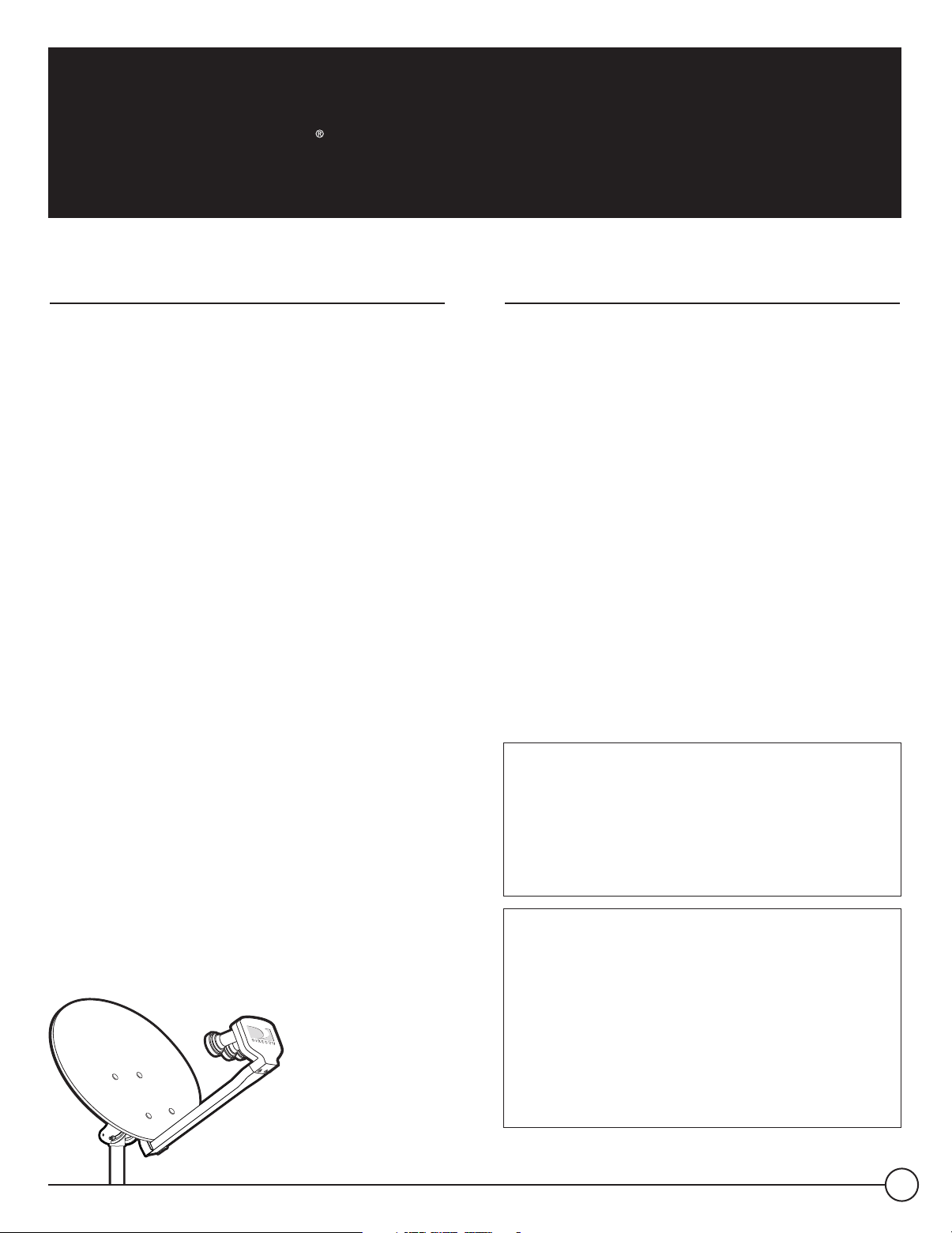
Installation Manual
DIRECTV Multi-Satellite Dish Antenna with
Integrated Triple LNB and Built-in Multi-Switch
Introduction
Your DI RE CTV Multi-S atellite Dish antenna is designed for use
with up to four independently operating DIR E CTV R eceivers.
Along with your receiver U ser Manual, this guide will provide
the information you’ll need to successfully install and operate
your DIR ECTV S ystem. Throughout the manual, the DI R ECTV
Multi-Satellite Dish antenna will be referred to as the “ antenna.”
For best results, we suggest you read carefully through these
pages first before beginning installation. The guide is intended
for an individual experienced in performing the various tasks
described, including:
•
Determining an antenna location with a good southerly
view of the satellites
•
Climbing a ladder and working on your roof
•
Observing safe working practices around heights and
electric al hazards
•
Determining if there are water pipes, gas lines or wiring
hidden near where you may drill
•
Using a power drill to drill holes into your house
Safety Information
Local building and electrical codes (NE C) require the
antenna and the coaxial cables to be connected to a
grounding electrode. I mproper installation may seriously
damage the equipment or the building, as well as cause
injury or death to you. For your own safety, follow these
important safety rules or c ontact a licensed inspector or
electrician in your area for assistance:
•
If you will be mounting your antenna in a loc ation where it
will be difficult or dangerous to view the attached bubble
level (see page 6 ), use a small mirror or plumbing level
instead. DO N OT risk falling
•
Perform as many functions as possible on the ground
•
Do not install the antenna on a rainy, snowy or windy day
•
Make sure there are no people, pets, etc. below when you
are working on the roof
•
Watch out for power lines which may be overhead,
underground and/or hidden behind walls, keeping safely clear
of them with ladders, antenna and tools during installation
•
R outing coaxial cable(s) through foundation, wall,
under-floor, attic or interior walls
•
S afely lifting and securing the 2 0-lb. antenna assembly
•
Grounding the antenna and cable(s) as recommended
in the National E lectric Code (NEC)*
NOTE: If you don’t feel c ompletely comfortable with these
tasks, simply contact the store where you purchased the
system for information on having your system installed by
a local authorized DI R ECTV installer.
FUNAI CORPORATION, INC./DX ANTENNA
The Federal Communications Commission (FCC) has ruled that
a local government or homeowner’s association may not prevent
the installation of satellite antennas one meter or smaller in
diameter, unless legitimate safety restrictions such as fire codes
are in effect. Call FCC tel: (202) 418-0163; FCC Web s ite at
http://www.fcc. gov/cgb/satellite.html or
http://www.fcc. gov/mb/facts/otard.html for more information.
ACTIVATION OF PR OGR AMMING MAY B E S UB J E CT TO CR EDIT
APP R OVAL AND R EQUIR E S VALID S ERVICE ADDR ESS , SOCIAL
SE CU R ITY NUMB ER AND/OR MAJ OR CR EDIT CAR D. DEP OSIT
OR PR EPAYMEN T MAY B E R E QUIR ED. P rogramming subject to
change. You must be physically located in the U . S. to be an
authorized DIR E CT V customer. DIR E CTV services not provided
outside the U. S . DIR ECTV programming is sold separately and
independently of DIR ECTV S ystem hardware. A valid programming
subscription is required to operate DIR ECTV S ystem hardware.
Activate your DIR ECT V programming today at 1-800-DIR ECTV
(1-80 0-347-3288).
*N EC is published by the N ational Fire Protection Association, 1 B atterymarch Park,
Quincy, Massachus etts, 022 69-9101 and may be available at your local public library.
DIRECTV Multi-Satellite Dish Antenna
1
Page 2
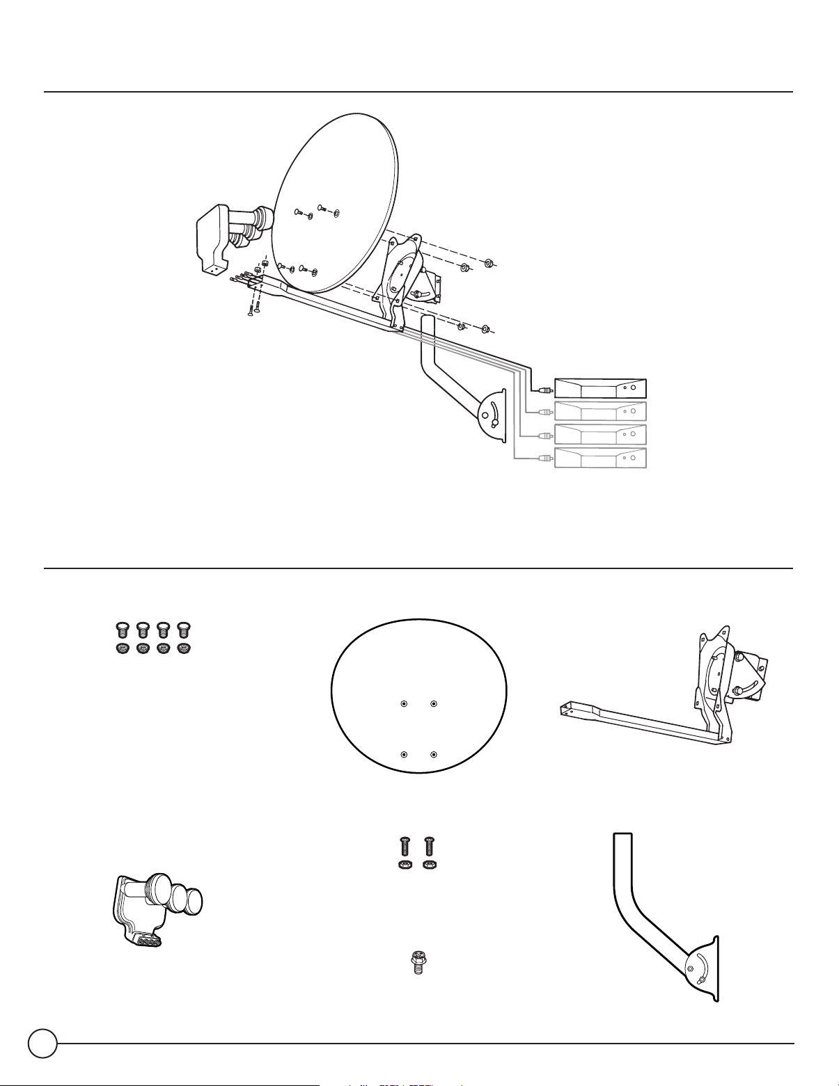
Antenna Assembly Overview
Contents of Package
Dish Mounting Hardware Multi-Satellite Dish R eflector LNB Arm/Antenna B ack Assembly
Triple-head, Multi-S atellite LNB Mounting H ardware
LNB with B uilt-in Multi-S witch for
four Independent Outputs
Grounding S crew
E ZAL I GN™ Mast
2
Page 3
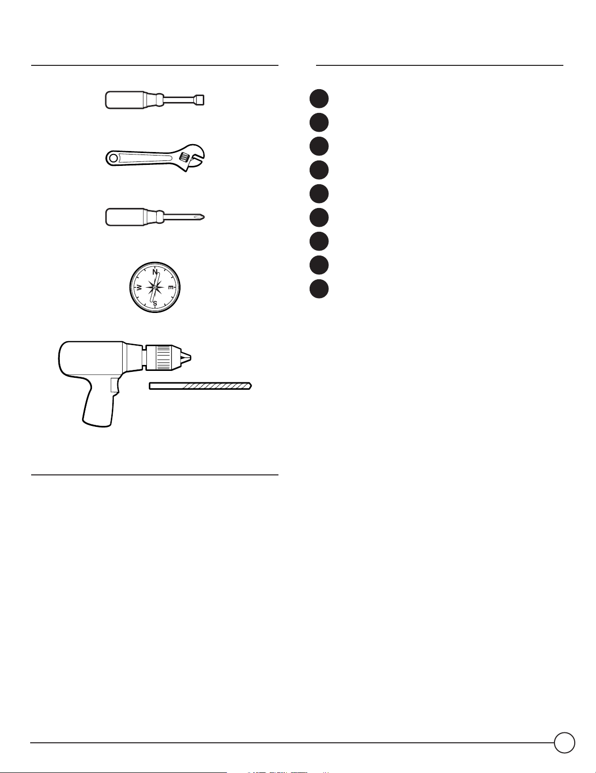
Tools Required
Steps for Installation
7/16 " Nut Driver
Adjustable Wrench
S crewdriver (Phillips)
Magnetic Compass
E lectric Drill and B it
In the following pages, you’ll find step-by-step ins tructions for:
1 Determining Coordinates for Aiming Antenna .. .. . .. . page 4
2 Finding S uitable Antenna S ite ... . .. . .. . . .. . .. . . .. . .. . . .. . . page 5
3 Installing E ZALIGN™ Mast. . . .. . .. . . .. . .. . . .. . .. . . .. . .. . ... . .page 6
4 Assembling/Adjusting Antenna on Ground.. . .. . .. . . .. . .page 7
5 Attaching Antenna to Mast . . .. . ... . .. . .. . . .. . .. . . .. . .. . . .. . .. page 7
6 R outing R G 6 Cable(s) . . .. . . .. . .. . . .. . .. . . .. . .. . . .. . .. . ... . .. . .page 8
7 Grounding Cable and Antenna . . . .. . .. . . .. . .. . . .. . .. . ... . .. . page 8
8 Attaching LNB to Antenna .. . . .. . .. . . .. . .. . . .. . .. . ... . .. . .. . . .page 9
9 Aiming and Fine-tuning Antenna.. . .. . .. . . .. . .. . . .. . .. . . .. . page 9
Information Also Included:
Tr oubleshooting Check List for Initial I nstallation.. . ... . .. page 11
Loss of S ignal/Rain Fade. . .. . . .. . .. . . .. . .. . . .. . .. . ... . .. . ... . .. . .. . . page 1 2
Optional Accessories
Typical installation kits (sold separately) include:
• Mast base mounting hardware
• R G 6 coaxial cable(s) with F connectors
• Grounding hardware, grounding wire, wire clips, etc.
• 6 " plumbing level
(not included)
Installation with L ong Cable R un
.. . . .. . .. . . .. . .. . . .. . .. . ... . .. . .page 1 2
DIRECTV Multi-Satellite Dish Antenna
3
Page 4
ZIP Code
Enter your ZIP code.
99 92 96 98 3
Azimuth: 152
Elevation: 50
Tilt: 102
OK
Clear
Depending on your rec eiver
model, your display may look
different from shown. In this
example, a Southern California
ZIP code “ 92683” is entered
and rec eiver outputs :
• Azimuth: 152
• E levation: 50
• Tilt: 1 02
STEP
Determining Coordinates
1
for Aiming Antenna
The coordinates (Azimuth, Elevation and Tilt numbers) are
based on your ZI P code and can be determined easily by using
your receiver. You will need these numbers for site survey and
antenna adjustments.
NOTE: The antenna does not need to be installed for this step.
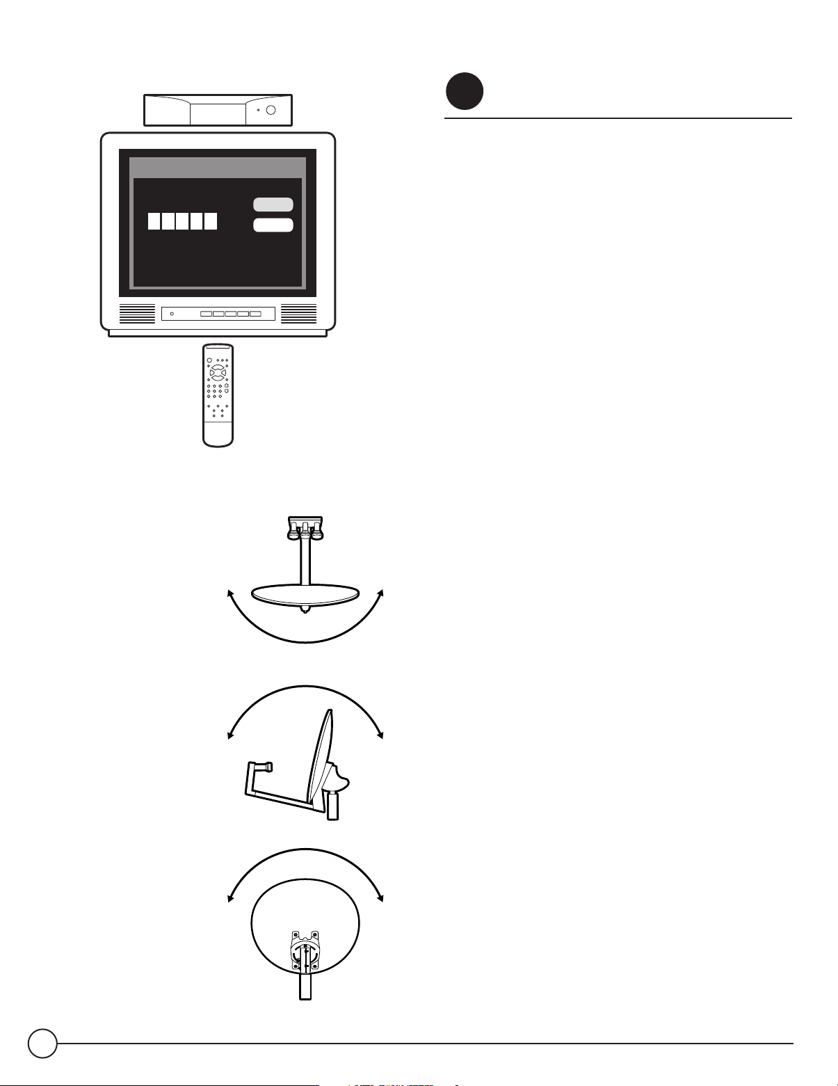
Connect your receiver to the TV
Consulting your receiver manual, connect the receiver's video
or Channel 3/4 outputs to the corresponding TV input. Turn on
the TV and the receiver.
Set the antenna type
Navigate to the antenna installation screen menu. S elect
installation as an “ oval 3 -sat” (some receiver brands may c all
it: “triple” , “ 3 sat location” , “ Sat 1 , 2 ,3 ” or “ Sat A, B ,C” ).
Find your coordinates
Navigate to the antenna-pointing menu screen. E nter your ZI P
code, then write down the numbers in space provided below.
Azimuth
(horizontal, side-side)
Elevation
(vertical, up/down)
Tilt
(dish reflector rotation)
__________
Your Azimuth
__________
Your Elevation
__________
Your Tilt
4
Page 5
Finding Suitable
STEP
2
Antenna Site
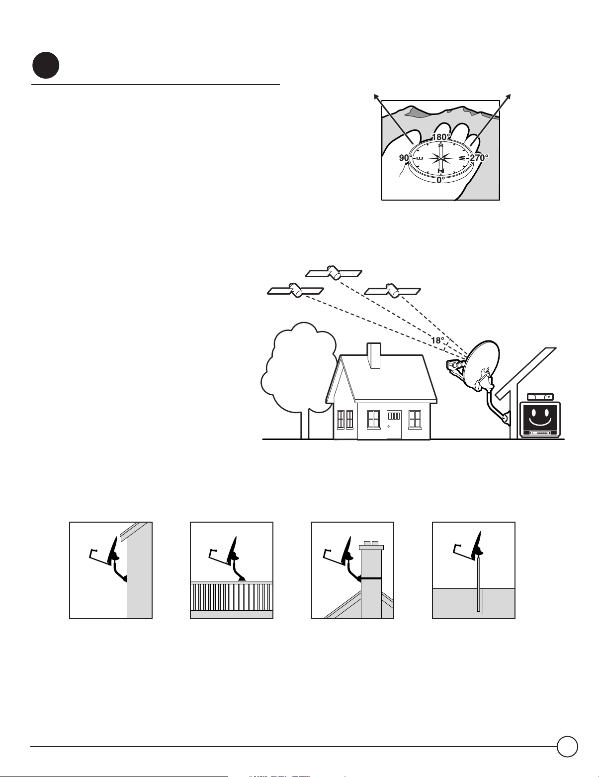
A suitable antenna site requires an unobstructed view of the
southern sky, a stable antenna mounting surface, a distance of
10 0 -ft or less for R G 6 cable from your antenna to your
receiver, and grounding nearby.
If you live on the West Coast, the
satellites will be to the south-southeast.
If you live on the East Coast, the
satellites will be to the southwes t.
NOTE: It'
s important to estimate the cable length at this point.
The DIR E CTV satellites are located in the southern sky above
the E quator. The location for your antenna must have
elevation-angle c learance (above the horizon) and 1 8 ° span
clearance (from 1 0 1WL to 11 9 WL) for an unobstructed view to
all three satellite locations. N orthern border states have
elevation readings toward 30 ° and southern border states
toward 6 0°.
NOTE: If you are replacing an 1 8 " dish
with a new Multi-S atellite Dish Antenna,
be sure to check for the required 1 8°
Sat A, 101
Transponders
# 1 to # 32
WL
with
clearance. If you do not have the
required clearance, you should use
a different location.
Sat C, 110
Converted Transponders
WL
# 8, #10, #12
with
Sat B , 119
Transponders
# 22 to # 32
WL
with
No trees, leaves, buildings can be in the line-of-sight
between antenna and satellites.
Due to the many configurations possible, mast-mounting hardware is not included. B e sure you have the necessary mounting hardware before you begin.
Optional mounting kits are available at your local electronics store. B elow are potential mounting sites.
Stucc o Exterior Wall Wooden R ail Chimney Ground
DIRECTV Multi-Satellite Dish Antenna
5
Page 6

View of bubble level on top of mast
Wrong
R ight
STEP
Now, you're ready to install the antenna mast at the location
you've chosen in S tep 2 and align it to be plumb (perfectly
straight up).
Dish antenna to rec eive optimal signals, and failure to align it
properly will result in difficulty acquiring signals as well as a
greater tendency for signal outages in adverse weather.
Mount the base securely
The mast base must be sturdy so antenna does not shift under
various weather conditions and its own weight. Mounting is
preferable on wood or masonry. U nsuitable sites may be
handrail, aluminum or vinyl siding, composite paneling, and
fiber/particle/strand boards.
CAUTION! When installing mast base, avoid placing finger
between mast bottom and base to prevent being pinched or cut.
Align the mast
•
Installing EZALIGN™Mast
3
Plumbing the mast is critical
The E ZAL I GN Mast pivots up and down, and from side to
side. A bubble level is located in the top of the mast to
assist in alignment.
for the Multi-S atellite
•
Loosen the four mast bolts slightly. Then move the mast
up/down or twist side-to-side until the bubble in the bubble
level is centered as shown at left.
CAUTION! If the mast is mounted in a location where it is
difficult or dangerous to view the bubble level, use a small
mirror or plumbing level instead. DO NOT reach out and risk
falling from roof or other high place.
Ti ghten mast bolts
When mast is straight up (plumbed), and while still keeping
hold of the mast, tighten the four bolts with a 7 /16" nut driver
with your other hand. Make sure bolts are secure. You may want
to tighten further with an adjustable wrench.
Up and Down Movement S ide to S ide Movement
6
Page 7

Assembling/Adjusting
STEP
4
Antenna on Ground
On even ground, attach dish to the L NB Arm/Antenna B ac k
Assembly as shown. Leave off the Triple-head LNB until the
antenna is mounted on the mast and you’ve routed cable
through the LNB Arm.
Set Tilt Adjustment
•
At the back of the antenna assembly, loosen the three T ilt
bolts and then set the Tilt adjustment according to the
coordinate number you obtained in S tep 1 .
•
Tighten the Tilt bolts.
again
from this point on (even if you could not find the
satellite signal during alignment). Unlike the E levation and
Azimuth coordinates, there is no need to fine-tune Tilt;
doing so may cause alignment difficulty. F or some of the
E astern S eaboard states, however, there maybe an
exception: see S tep 9, note # 2, on page 1 0.
Set Elevation Adjustment
•
At the side of the antenna assembly, loosen the two Elevation
bolts and two P ivot bolts (one on each side) and preliminarily
set the Elevation adjus tment, per the coordinate number
obtained in Step 1 .
Do not change the Tilt adjustment
Dish attaching to the LN B Arm/Antenna B ack Ass embly
In this example we have
for Southern California
(ZIP code 92683) ,
the Tilt setting is
102
°
.
Tilt P ointer
Tilt B olts
(One shown)
•
Tighten the Elevation bolts and Pivot bolts, but not completely.
This is a preliminary adjustment, which you may have to
fine-tune later on.
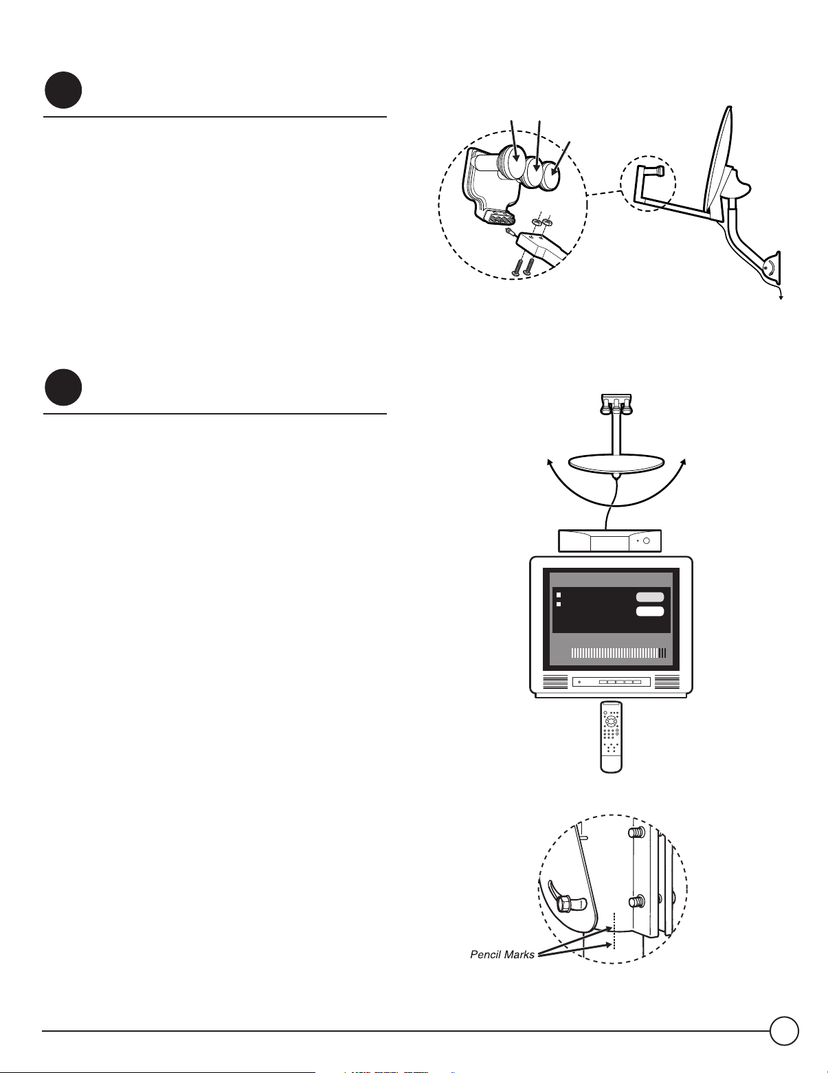
STEP
Attaching Antenna to Mast
5
•
S lide the back of the antenna assembly onto the top of the
mast until it stops. I f necessary, slightly loosen the two
Azimuth/Mast clamp bolts so the antenna will go on to the
mast.
•
Tighten the two Azimuth/Mast clamp bolts and the pivot
bolt just enough so the antenna has only side-to-side
movement ( rotational swing around the mast) for later
Azimuth alignment in S tep 9 .
In this example we show
for Southern California
(ZIP code 92 683) , the
Elevation setting is 50
(use the position of the
metal edge to the E levation
scale; do not use the washer
or the bolt as reference).
°
Metal edge
at 50
°
Elevation Bolts,
one on each side
Azimuth/
Mast Clamp B olts
Pivot B olt
DIRECTV Multi-Satellite Dish Antenna
7
Page 8

Alternate Grounding
Point
STEP
Routing RG 6 Cable(s)
6
You'll route R G 6 cable from your receiver to the cable grounding
block, then from the grounding block to the triple-head LNB .
B efore starting, inspect the inside of each cable connector for
foreign materials and/or short. Make sure that the copper center
conductor is straight and centered in the connector.
Run cable from receiver
Verify that there are no wires or pipes blocking the location
where you want to feed the coaxial cables into your home. Drill
a 1 /2 inch hole for each cable. Connect cable to the “ Sat I n”
jack on the back of your receiver. To prevent short, leave
receiver unplugged until S tep 9.
Connect to grounding block
Mount the grounding block c lose to the point of cable entry
into the house. Connect cable to grounding block as shown.
STEP
Grounding Cable and Antenna
7
Opti on #1
Grounding
Wire from
Antenna
Cold water
pipe only
Grounding
Wire from
Cable
Grounding
B lock
Us e grounding wires #10 copper or #8 aluminum
Opti on #2
Grounding Screw P oint
Grounding Wire
from Antenna
Grounding the antenna and cable grounding block help protect
the satellite receiver system and other components from
lightning damage.
•
Ground wire c an be attached anywhere on the metal part of
the antenna, but there is a convenient grounding screw at
one side of the mast base.
Installation should comply with
local codes and the National E lectric Code (NE C, Sections
25 0 and 8 10 ).
•
Grounding point can be outside metal cold water pipe at
point of entry (no gas or hot water pipes), 8 -foot ground rod,
grounded metallic service raceway, grounded electric service
equip enclosure, etc. Option #1: B oth ground wires go to the
same ground point. If the two grounding points are different,
a # 6 copper wire should be connected between them. Option
#2: The dish antenna grounding wire goes to grounding block
first, then to the grounding point.
Cold water pipe only
8
Grounding Wire from
Cable Grounding B lock
Page 9
STEP
Attaching LNB to Antenna
8
The triple-head L N B has four identical outputs, each
supporting one independently operating receiver. To simplify
future installation of additional rec eiver(s), you may want to
route more cables to the antenna at this point. Only one cable
is needed for antenna fine-tuning and alignment.
•
R G 6 cable from the grounding block can now be routed to
the LNB on your antenna. Attach the triple-head LNB onto
the LNB Arm and fasten with included mounting hardware
(P hilip screws and nuts). Dress cable with enclosed tie
wraps, allowing for cable water drip loop if necessary.
Aiming and
STEP
9
Fine-tuning Antenna
When you fine-tune the antenna to one satellite, the other two
satellites should be aligned automatically. Plug in and turn on
your receiver.
•
Use the on-screen signal strength meter to fine-tune the
antenna. It is important to obtain the strongest signal
possible; the higher the signal strength, the less likely you
are to experience signal outages during adverse weather.
Sat B ,
Sat C,
119WL
110WL
Sat A,
101WL
Hooking up cables (one shown) to the LN B and attaching the LNB
to Antenna — up to four c ables can be connected this way.
Align the
Azimuth
•
With a cell phone and house phone, ask someone to relay
signal strength values to you, or hook-up a portable TV at the
installation site. Your receiver may be equipped with an
audible beep tone feature; the higher pitch, the higher the
signal. A hand-held signal meter is also an option.
Align the Azimuth
•
S et your on-screen menu to the signal meter mode, on
S atellite A (1 01WL). U se a transponder that is unique to
S at A (such as 1 - 6 , 1 6 ) for your alignment. P oint the
antenna to a generally southerly direction, or use the
Azimuth number obtained in S tep 1 and a compass for
a more precise starting point.
•
Very slowly rotating the antenna around the mast a few
degrees at a time, pause 3 - 5 seconds in between for signal
strength meter update. You should be able to find the
satellite signal first and then the signal peak, indic ated on
your screen. Once you sweep through the peak-signal point
on the screen, stop. You may want to swing pass the peak
point a couple of times to make sure.
•
Mark the mast and antenna bracket point with a pencil.
Antenna
Transponder: 1 , S at A
Antenna Location:
Azimuth: 152
Elevation: 50
Tilt: 1 02
Current Level: 0 Pea k Level: 85
Signal:
OK
Clear
DIRECTV Multi-Satellite Dish Antenna
9
Page 10

Verify Azimuth
Alignment
Antenna
Transponder: 23, Sat B
Antenna Location:
Azimuth: 152
Elevation: 50
Tilt: 1 02
Current Level: 0 Pea k Level: 75
Signal:
OK
Clear
Verify Azimuth alignment
S witch to S at B (1 1 9 WL ) on your on-screen menu, using
Transponders 2 3 , 2 5 , 2 9 or 31 . Verify that signal is also
peaked at 11 9 WL by very slightly rotating the antenna around
the penciled marking on the mast. Once satisfied, tighten the
two Azimuth/Mast clamp bolts.
NOTE: Sat B (1 19 WL) signal strength may read different than
S at A (1 01 WL ) signal strength, depending on the satellite
transmission patterns in the area. You only need to see
whether S at B (11 9 WL ) is peaked and not try to compare signal
strength numbers. It's OK to be close but not at the peaks for
both locations simultaneously.
Fine-tune the Elevation
Use S at B (1 1 9WL) or S at A (1 0 1WL) on-screen signal meter.
While holding the LNB Arm, slightly loosen the two E levation
bolts and two Pivot bolts. Move it up/down slightly and observe
the signal strength on the screen. Find the peak and tighten the
two E levation bolts and two P ivot bolts.
Verify satellite signals
Confirm the final signal-peak readings at all three satellite
locations. Sat C (1 1 0 WL , Transponders 8, 10 and 12 . ) should
be aligned automatically.
Fine-tune the
Elevation
Antenna
Transponder: 1 , S at A
Antenna Location:
Azimuth: 152
Elevation: 50
Tilt: 1 02
Current Level: 0 Pea k Level: 91
Signal:
OK
Clear
NOTE 1: Occ asionally, you may see a transponder at S at A
(1 01WL), S at B (11 9 WL) or S at C (1 10 WL ) not active, it is
possible that this transponder is reserved for upcoming
programming expansion. S witch to other transponders at the
same satellite location to verify that you have good readings and
that your antenna alignment is satisfactory.
NOTE 2: I n most of the U . S ., the Tilt Adjustment should be
fixed. However, because of large Tilt angle to 1 19 WL satellite
in E astern S eaboard states, a small amount of Tilt fine-tuning
adjustment may improve 11 9 WL signal strength without
significantly changing 1 01 WL signal reading. F or these states,
the following Tilt fine-tuning procedures are recommended:
1. F ollow alignment procedures from S tep 1 through S tep 9;
tighten E levation bolts, P ivot bolts and Mast clamp bolts.
2. F ine-tune T ilt Adjustment first by +3 degrees and then
-3 degrees. T ilt is optimized when you see the 1 01 WL
signal reading essentially unchanged and 11 9 WL signal
strength improved by several points. S et Tilt to the
optimized point and tighten T ilt bolts.
10
Page 11

Troubleshooting Check List for Initial Installation
If the signal is not found, be sure the receiver user manual and the antenna installation manual have been properly followed. Check to:
Make sure all cable connections are correct and each
connection is seated/tightened properly.
Inspect the inside of each cable connector for dirt or
possible connector to case/shield short.
Verify the Azimuth, E levation and Tilt angles for your
location by ZI P code.
Make sure the Tilt and E levation pointers are aligned
correctly to the scales. Do not use washer or bolt as
reference.
Make sure the Tilt adjustment is
recommended setting for the antenna location.
Make sure the bubble level frame inside the mast is
seated properly, then check the mast alignment again.
The mast not being plumb
of alignment difficulty.
R emove existing TV-specific components, such as TV
splitter, etc; reduce the installation to the basic
connections called out in this guide. S uch components
may not work with the satellite signal and they may be in
the wall where you can’t see them. When in doubt, run R G
6 cable directly to your receiver.
not changed
/up straight is a major cause
from the
Your triple-head L N B depends on the receiver to supply
power; the longer the cable length to the LNB , the greater
the DC voltage drop. Your receiver depends on the antenna
to supply signal; the longer the cable length, the greater
the signal amplitude attenuation. Therefore, R G 6 cable
length much longer than 10 0 feet (from each the receiver
to the antenna) should be avoided.
R G 6 cable with solid copper center conductor is highly
recommended because it has much lower DC voltage drop
compared to R G 6 cable with a copper-coated, steel c enter
conductor.
S tandard R G 5 9 cable causes too much DC drop and
signal drop; it can not be used to pass the satellite signal.
R G 6 coaxial cable must be used.
S ome after-market, off-the-shelf add-on c omponents may
not be as advertised. They might not work or could c ause
additional DC drops and signal amplitude attenuation.
R emove such components, go back to the basic
connections called out in this manual and re-verify.
Make sure the satellite cable is connected to the “ S at In”
jack, not the “ Antenna I n” jack. The “ Antenna I n” jack
at the back of the receiver is for off-air antenna input or
cable TV input.
Make sure there are no obstructions (trees, buildings,
windows, corner or overhang of your roof, your body or
hands) - the signal does not pass leaves, branches, glass,
etc. Also, keep in mind the 1 8 ° span clearance to receive
all three satellite locations. T his required clearance may
also mean you’ll need to consider a new location when
replacing an old 18 " dish with this new Multi-S atellite Dish
Antenna.
Make sure the Access Card from your receiver is fully
inserted into the Access Card slot and oriented c orrectly.
If you live in a state on the E astern S eaboard, you may
need to fine-tune your T ilt Adjustment. F ollow directions
from NOTE 2 , page 1 0 .
If all are done correctly but the signal is still not found,
change the E levation adjustment of the antenna slightly
(± 2 °, then ± 4 ° from the called-for setting) and repeat the
procedure.
DIRECTV Multi-Satellite Dish Antenna
11
Page 12

Loss of Signal/Rain Fade
•
The satellite signal may be lost temporarily due to
unusually heavy rainfall. An optimally aligned antenna,
along with the shortest possible cable run, minimizes
the chances of “ rain fade.”
•
Make sure the antenna is mounted securely to prevent it
from being blown out of alignment in a heavy wind.
•
Heavy snow accumulation on the LNB and the antenna may
reduce the satellite signal strength; snow should be swept
away as soon as possible.
•
Tr ee foliage growth into antenna’s line-of-sight to the
satellite may result in gradual loss of picture.
Installation with Long Cable Run
•
For installations where the R G 6 cable runs from the
receiver(s) to the L NB far exceeds 100 feet (1 5 0 feet or
more), as encountered in a commercial or multi-dwelling
building, you need to use an AC power booster module to
bias the L N B .
•
You will also need an additional R F signal amplifier to
compensate the signal amplitude loss. Otherwise, your
antenna and receiver may not work properly and be subject
to frequent outages in adverse weather. Contact a
professional concerning such installations.
12
© 2003 DIRE CTV, I nc. DI RE CTV, the Cyclone Design logo and EZALIGN are trademarks of
DIR ECTV, Inc., a unit of H ughes Electronic s Corporation. 07/02 12429E NG-0
DSA-2 0MA
E -39 21
 Loading...