

Funai BH2-M200 Service Manual

SERVICE MANUAL
HDD & BLU-RAY DISC
RECORDER
BH2-M200

TABLE OF CONTENTS
Specifications . . . . . . . . . . . . . . . . . . . . . . . . . . . . . . . . . . . . . . . . . . . . . . . . . . . . . . . . . . . . . . . . . . . . . . . . . . 1-1-1
Laser Beam Safety Precautions . . . . . . . . . . . . . . . . . . . . . . . . . . . . . . . . . . . . . . . . . . . . . . . . . . . . . . . . . . . . 1-2-1
Important Safety Precautions . . . . . . . . . . . . . . . . . . . . . . . . . . . . . . . . . . . . . . . . . . . . . . . . . . . . . . . . . . . . . . 1-3-1
Standard Notes for Servicing . . . . . . . . . . . . . . . . . . . . . . . . . . . . . . . . . . . . . . . . . . . . . . . . . . . . . . . . . . . . . . 1-4-1
Handling Precautions for HDD . . . . . . . . . . . . . . . . . . . . . . . . . . . . . . . . . . . . . . . . . . . . . . . . . . . . . . . . . . . . . 1-5-1
Cabinet Disassembly Instructions. . . . . . . . . . . . . . . . . . . . . . . . . . . . . . . . . . . . . . . . . . . . . . . . . . . . . . . . . . . 1-6-1
How to Initialize the HDD & BLU-RAY Disc Recorder. . . . . . . . . . . . . . . . . . . . . . . . . . . . . . . . . . . . . . . . . . . . 1-7-1
Firmware Renewal Mode . . . . . . . . . . . . . . . . . . . . . . . . . . . . . . . . . . . . . . . . . . . . . . . . . . . . . . . . . . . . . . . . . 1-8-1
BD/HDD Main CBA Unit Replacement . . . . . . . . . . . . . . . . . . . . . . . . . . . . . . . . . . . . . . . . . . . . . . . . . . . . . . .1-9-1
How to Format the HDD after Replacement . . . . . . . . . . . . . . . . . . . . . . . . . . . . . . . . . . . . . . . . . . . . . . . . . . 1-10-1
How to Display the LD Operating Time . . . . . . . . . . . . . . . . . . . . . . . . . . . . . . . . . . . . . . . . . . . . . . . . . . . . . . 1-11-1
Troubleshooting . . . . . . . . . . . . . . . . . . . . . . . . . . . . . . . . . . . . . . . . . . . . . . . . . . . . . . . . . . . . . . . . . . . . . . . . 1-12-1
Error Display on the Front Panel . . . . . . . . . . . . . . . . . . . . . . . . . . . . . . . . . . . . . . . . . . . . . . . . . . . . . . . . . . .1-13-1
Block Diagrams . . . . . . . . . . . . . . . . . . . . . . . . . . . . . . . . . . . . . . . . . . . . . . . . . . . . . . . . . . . . . . . . . . . . . . . . 1-14-1
Schematic Diagrams / CBA and Test Points. . . . . . . . . . . . . . . . . . . . . . . . . . . . . . . . . . . . . . . . . . . . . . . . . . 1-15-1
Waveforms . . . . . . . . . . . . . . . . . . . . . . . . . . . . . . . . . . . . . . . . . . . . . . . . . . . . . . . . . . . . . . . . . . . . . . . . . . . 1-16-1
Wiring Diagram . . . . . . . . . . . . . . . . . . . . . . . . . . . . . . . . . . . . . . . . . . . . . . . . . . . . . . . . . . . . . . . . . . . . . . . .1-17-1
IC Pin Function Descriptions. . . . . . . . . . . . . . . . . . . . . . . . . . . . . . . . . . . . . . . . . . . . . . . . . . . . . . . . . . . . . . 1-18-1
Lead Identifications . . . . . . . . . . . . . . . . . . . . . . . . . . . . . . . . . . . . . . . . . . . . . . . . . . . . . . . . . . . . . . . . . . . . . 1-19-1
Exploded Views. . . . . . . . . . . . . . . . . . . . . . . . . . . . . . . . . . . . . . . . . . . . . . . . . . . . . . . . . . . . . . . . . . . . . . . . 1-20-1
Mechanical Parts List . . . . . . . . . . . . . . . . . . . . . . . . . . . . . . . . . . . . . . . . . . . . . . . . . . . . . . . . . . . . . . . . . . . 1-21-1
Electrical Parts List . . . . . . . . . . . . . . . . . . . . . . . . . . . . . . . . . . . . . . . . . . . . . . . . . . . . . . . . . . . . . . . . . . . . .1-22-1
Manufactured under license from Dolby Laboratories.
Dolby and the double-D symbol are trademarks of Dolby Laboratories.
1-1-1 E4V21SP
SPECIFICATIONS
Specifications
Note
The specifications and design of this product are subject to change without notice.
General
HDD Internal 3.5 inch HDD 500 GB
Power requirements 220–240 V ± 10 %, 50 Hz ± 0.5 %
Power consumption 34 W
Power consumption (standby) 0.7 W
Weight 4.0 kg
Dimensions (width x height x depth) 430 x 61 x 315 mm
Operating temperature 5°C to 40°C
Operating humidity Less than 80% (no condensation)
TV system PAL-B/G, SECAM-LL’
Recording
Recording format BDAV format (BD-RE, BD-R), Video Recording (VR) format (DVD-RW only),
video format (DVD-RW, DVD-R), +VR format (DVD+RW, DVD+R)
Recordable discs BD-RE, BD-R, DVD-ReWritable, DVD-Recordable, DVD+ReWritable,
DVD+Recordable
Video recording format
Sampling frequency
Compression format
13.5 MHz
MPEG
Audio recording format
Sampling frequency
Compression format
48 kHz
Dolby Digital
Linear PCM (XP mode)
Dolby Digital Plus (TS mode)
MPEG (TS mode)
Tu ner
DVB-T channels
VHF
UHF
F5 - F10
E21 - E69
Input/Output
Front Panel:
SD card input SD card slot
USB port
TYPE A
USB 2.0
Rear Panel:
VHF/UHF antenna input/output terminal 75 :
Audio input /output Two 21-pin scart sockets (AV1, AV2)
Video input /output
Input /output level
Two 21-pin scart sockets (AV1, AV2)
1 Vp-p (75 :) each
Audio output
Output level
Two RCA connectors
2 Vrms (output impedance less than 1 k:)
Video output
Output level
One RCA connector
1 Vp-p (75 :)
Digital audio output
Output level
One Coaxial pin jack
500 mVp-p (75 :)
HDMI output HDMI jack
LAN terminal 10 BASE-T / 100 BASE-TX
1-2-1 BH2PLBSP(1VM437539A)
LASER BEAM SAFETY PRECAUTIONS
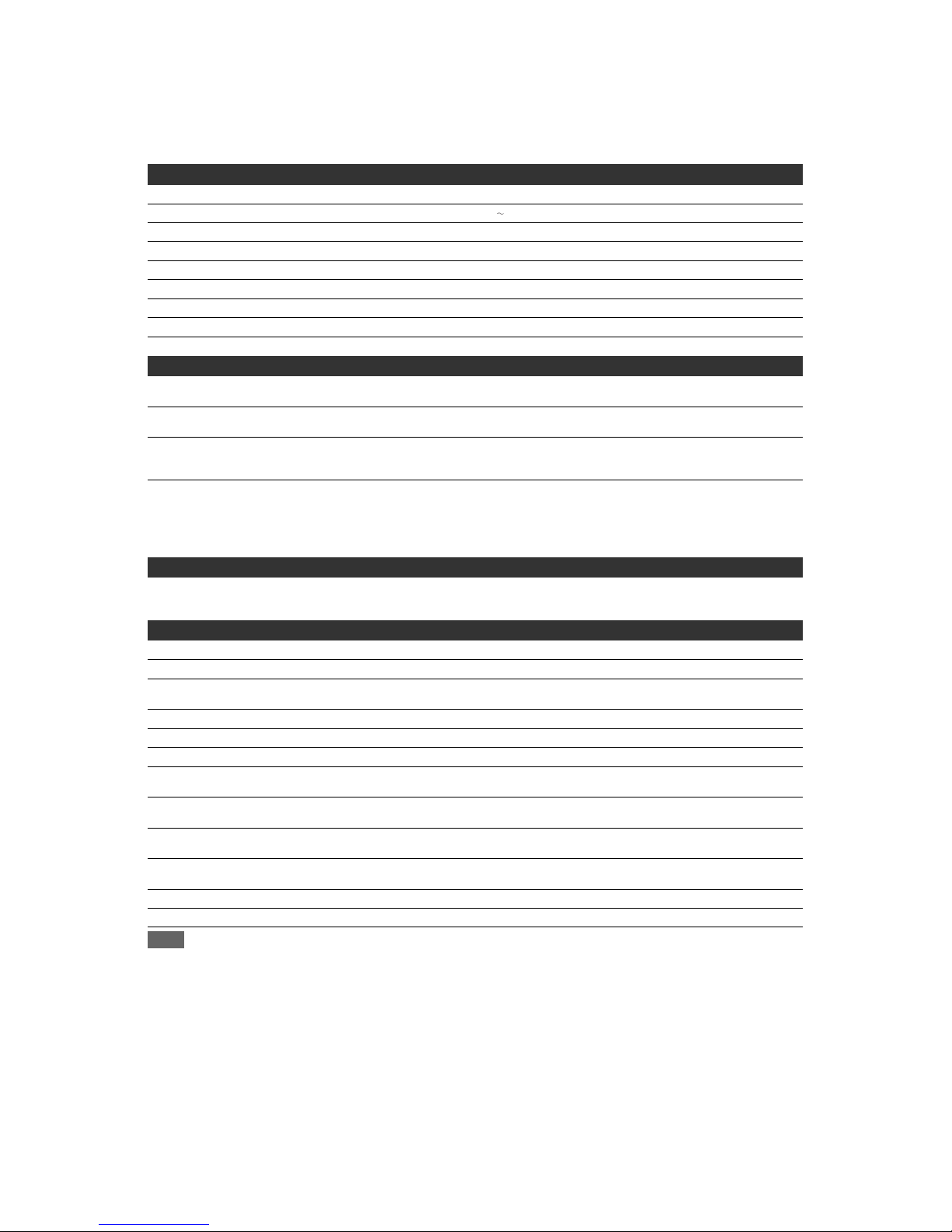
This BD player uses a pickup that emits a laser beam.
The laser beam is emitted from the location shown in the figure. When checking the laser diode, be sure to keep
your eyes at least 30 cm away from the pickup lens when the diode is turned on. Do not look directly at the laser
beam.
CAUTION: Use of controls and adjustments, or doing procedures other than those specified herein, may result in
hazardous radiation exposure.
Location: Inside Top of BD mechanism.
Do not look directly at the laser beam coming
from the pickup or allow it to strike against your
skin.
Drive Mechanism Assembly
Laser Beam Radiation
Laser Pickup
Turntable

1-3-1 BDP_ISP
IMPORTANT SAFETY PRECAUTIONS
Product Safety Notice
Some electrical and mechanical parts have special
safety-related characteristics which are often not
evident from visual inspection, nor can the protection
they give necessarily be obtained by replacing them
with components rated for higher voltage, wattage,
etc. Parts that have special safety characteristics are
identified by a ! on schematics and in parts lists. Use
of a substitute replacement that does not have the
same safety characteristics as the recommended
replacement part might create shock, fire, and/or other
hazards. The Product’s Safety is under review
continuously and new instructions are issued
whenever appropriate. Prior to shipment from the
factory, our products are carefully inspected to confirm
with the recognized product safety and electrical
codes of the countries in which they are to be sold.
However, in order to maintain such compliance, it is
equally important to implement the following
precautions when a set is being serviced.
Precautions during Servicing
A. Parts identified by the ! symbol are critical for
safety. Replace only with part number specified.
B. In addition to safety, other parts and assemblies
are specified for conformance with regulations
applying to spurious radiation. These must also be
replaced only with specified replacements.
Examples: RF converters, RF cables, noise
blocking capacitors, and noise blocking filters, etc.
C. Use specified internal wiring. Note especially:
1) Wires covered with PVC tubing
2) Double insulated wires
3) High voltage leads
D. Use specified insulating materials for hazardous
live parts. Note especially:
1) Insulation tape
2) PVC tubing
3) Spacers
4) Insulators for transistors
E. When replacing AC primary side components
(transformers, power cord, etc.), wrap ends of
wires securely about the terminals before
soldering.
F. Observe that the wires do not contact heat
producing parts (heatsinks, oxide metal film
resistors, fusible resistors, etc.).
G. Check that replaced wires do not contact sharp
edges or pointed parts.
H. When a power cord has been replaced, check that
5~6 kg of force in any direction will not loosen it.
I. Also check areas surrounding repaired locations.
J. Be careful that foreign objects (screws, solder
droplets, etc.) do not remain inside the set.
K. When connecting or disconnecting the internal
connectors, first, disconnect the AC plug from the
AC outlet.
L. When reassembling, be sure to use the original
screws or specified screws listed in the parts list.
1-3-2 BDP_ISP
Safety Check after Servicing
Examine the area surrounding the repaired location for
damage or deterioration. Observe that screws, parts,
and wires have been returned to their original positions.
Afterwards, do the following tests and confirm the
specified values to verify compliance with safety
standards.
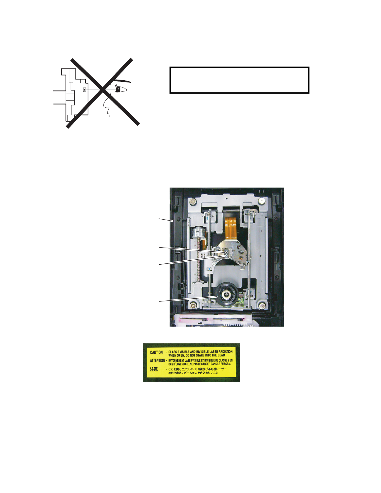
1. Clearance Distance
When replacing primary circuit components, confirm
specified clearance distance (d) and (d’) between
soldered terminals, and between terminals and
surrounding metallic parts. (See Fig. 1)
Table 1 : Ratings for selected area
Note: This table is unofficial and for reference only.
Be sure to confirm the precise values.
2. Leakage Current Test
Confirm the specified (or lower) leakage current
between B (earth ground, power cord plug prongs) and
externally exposed accessible parts (RF terminals,
antenna terminals, video and audio input and output
terminals, microphone jacks, earphone jacks, etc.) is
lower than or equal to the specified value in the table
below.
Measuring Method (Power ON) :
Insert load Z between B (earth ground, power cord plug
prongs) and exposed accessible parts. Use an AC
voltmeter to measure across the terminals of load Z.
See Fig. 2 and the following table.
AC Line Voltage Clearance Distance (d), (d’)
230 V
≥ 3.2 mm(d)
≥ 6.0 mm(d’)
Chassis or Secondary Conductor
Primary Circuit
Fig. 1
d' d
AC Voltmeter
(High Impedance)
Exposed Accessible Part
B
One side of
Power Cord Plug Prongs
Z
Fig. 2
Table 2: Leakage current ratings for selected areas
Note: This table is unofficial and for reference only. Be sure to confirm the precise values.
AC Line Voltage Load Z Leakage Current (i)
One side of power cord plug
prongs (B) to:
230 V
2kΩ RES.
Connected in
parallel
i≤0.7mA AC Peak
i≤2mA DC
RF or
Antenna terminals
50kΩ RES.
Connected in
parallel
i≤0.7mA AC Peak
i≤2mA DC
A/V Input, Output
1-4-1 BDP_SN
STANDARD NOTES FOR SERVICING
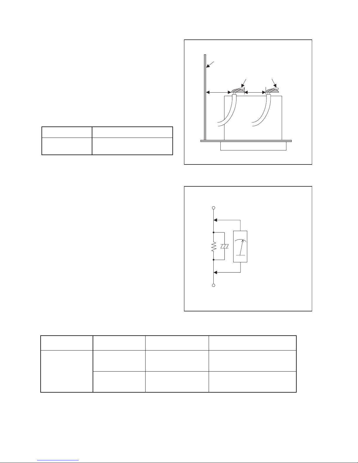
Circuit Board Indications
1. The output pin of the 3 pin Regulator ICs is
indicated as shown.
2. For other ICs, pin 1 and every fifth pin are
indicated as shown.
3. The 1st pin of every male connector is indicated as
shown.
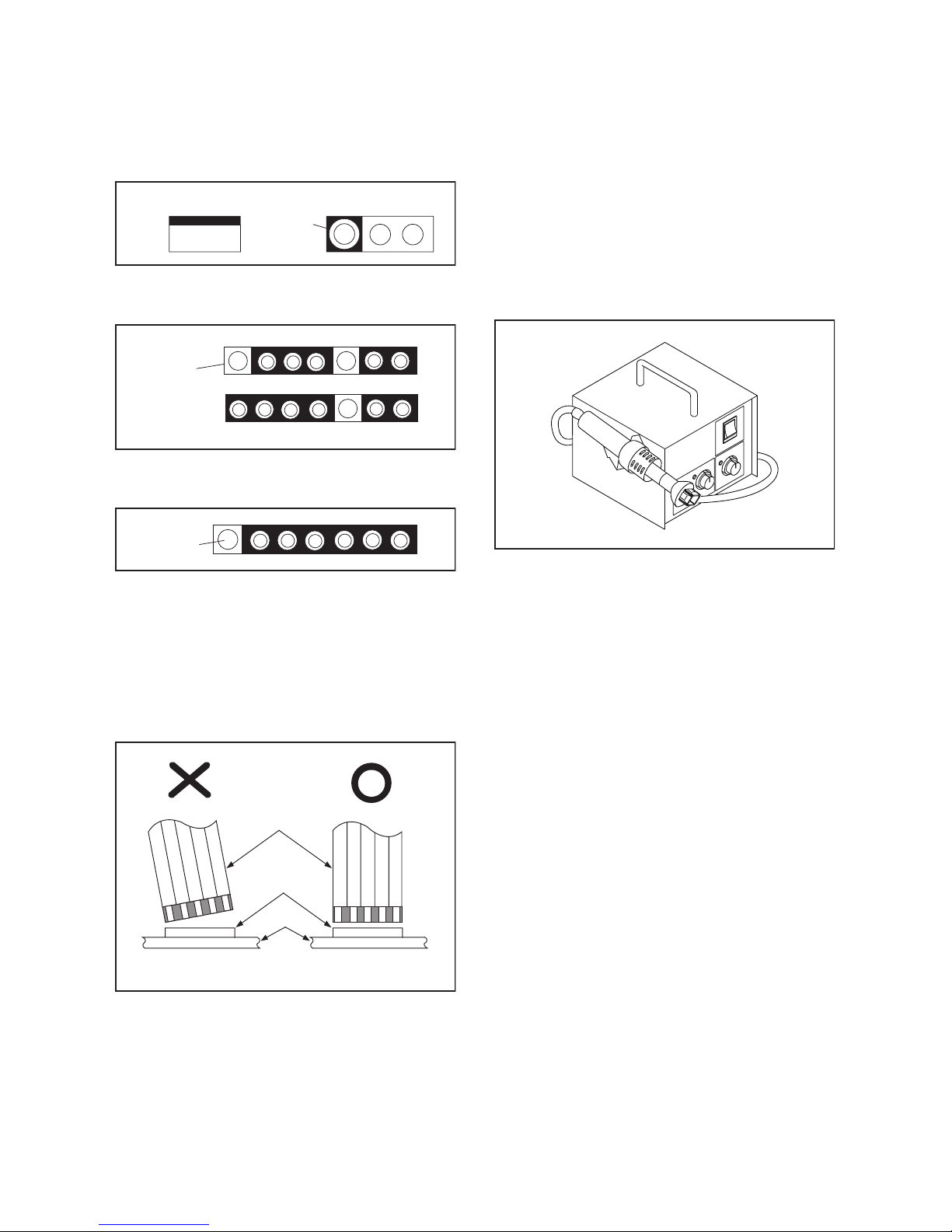
Instructions for Connectors
1. When you connect or disconnect the FFC (Flexible
Foil Connector) cable, be sure to first disconnect
the AC cord.
2. FFC (Flexible Foil Connector) cable should be
inserted parallel into the connector, not at an
angle.
Pb (Lead) Free Solder
When soldering, be sure to use the Pb free solder.
How to Remove / Install Flat Pack-IC
1. Removal
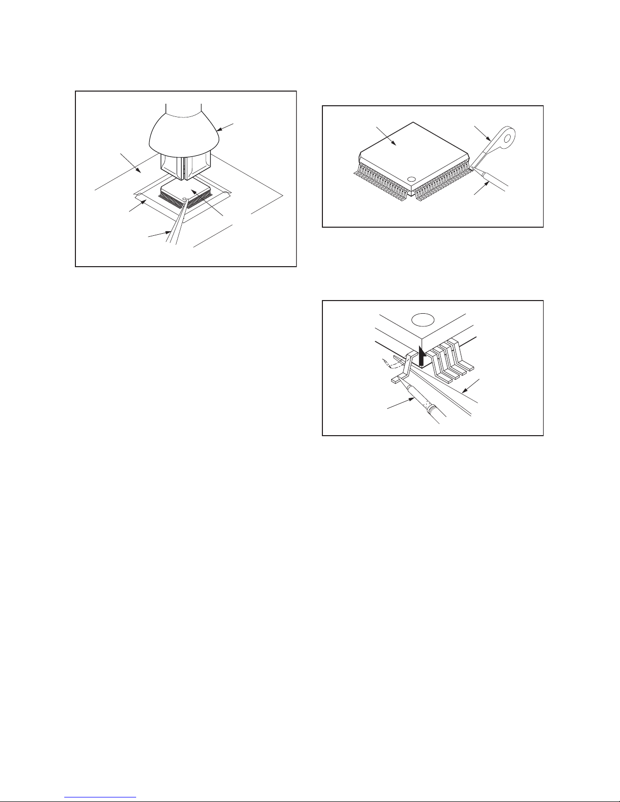
With Hot-Air Flat Pack-IC Desoldering Machine:
1. Prepare the hot-air flat pack-IC desoldering
machine, then apply hot air to the Flat Pack-IC
(about 5 to 6 seconds). (Fig. S-1-1)
2. Remove the flat pack-IC with tweezers while
applying the hot air.
3. Bottom of the flat pack-IC is fixed with glue to the
CBA; when removing entire flat pack-IC, first apply
soldering iron to center of the flat pack-IC and heat
up. Then remove (glue will be melted). (Fig. S-1-6)
4. Release the flat pack-IC from the CBA using
tweezers. (Fig. S-1-6)
CAUTION:
1. The Flat Pack-IC shape may differ by models. Use
an appropriate hot-air flat pack-IC desoldering
machine, whose shape matches that of the Flat
Pack-IC.
2. Do not supply hot air to the chip parts around the
flat pack-IC for over 6 seconds because damage
to the chip parts may occur. Put masking tape
around the flat pack-IC to protect other parts from
damage. (Fig. S-1-2)
To p Vie w
Out
In
Bottom View
Input
5
10
Pin 1
Pin 1
FFC Cable
Connector
CBA
* Be careful to avoid a short circuit.
Fig. S-1-1
1-4-2 BDP_SN
3. The flat pack-IC on the CBA is affixed with glue, so
be careful not to break or damage the foil of each
pin or the solder lands under the IC when
removing it.
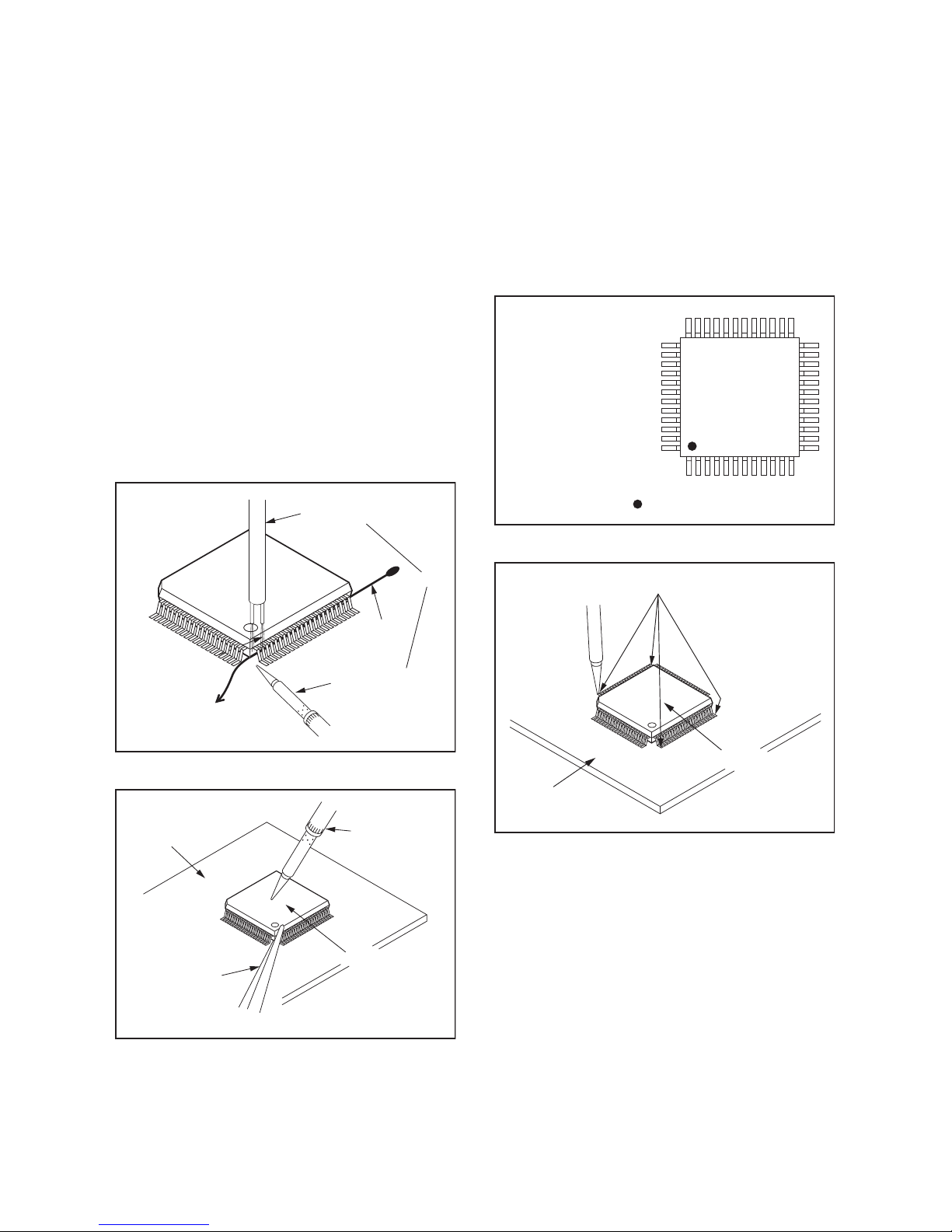
With Soldering Iron:
1. Using desoldering braid, remove the solder from
all pins of the flat pack-IC. When you use solder
flux which is applied to all pins of the flat pack-IC,
you can remove it easily. (Fig. S-1-3)
2. Lift each lead of the flat pack-IC upward one by
one, using a sharp pin or wire to which solder will
not adhere (iron wire). When heating the pins, use
a fine tip soldering iron or a hot air desoldering
machine. (Fig. S-1-4)
3. Bottom of the flat pack-IC is fixed with glue to the
CBA; when removing entire flat pack-IC, first apply
soldering iron to center of the flat pack-IC and heat
up. Then remove (glue will be melted). (Fig. S-1-6)
4. Release the flat pack-IC from the CBA using
tweezers. (Fig. S-1-6)
Hot-air
Flat Pack-IC
Desoldering
Machine
CBA
Flat Pack-IC
Tweezers
Masking
Ta pe
Fig. S-1-2
Flat Pack-IC
Desoldering Braid
Soldering Iron
Fig. S-1-3
Fine Tip
Soldering Iron
Sharp
Pin
Fig. S-1-4
1-4-3 BDP_SN
With Iron Wire:
1. Using desoldering braid, remove the solder from
all pins of the flat pack-IC. When you use solder
flux which is applied to all pins of the flat pack-IC,
you can remove it easily. (Fig. S-1-3)
2. Affix the wire to a workbench or solid mounting
point, as shown in Fig. S-1-5.
3. While heating the pins using a fine tip soldering
iron or hot air blower, pull up the wire as the solder
melts so as to lift the IC leads from the CBA
contact pads as shown in Fig. S-1-5.
4. Bottom of the flat pack-IC is fixed with glue to the
CBA; when removing entire flat pack-IC, first apply
soldering iron to center of the flat pack-IC and heat
up. Then remove (glue will be melted). (Fig. S-1-6)
5. Release the flat pack-IC from the CBA using
tweezers. (Fig. S-1-6)
Note: When using a soldering iron, care must be
taken to ensure that the flat pack-IC is not
being held by glue. When the flat pack-IC is
removed from the CBA, handle it gently
because it may be damaged if force is applied.
2. Installation
1. Using desoldering braid, remove the solder from
the foil of each pin of the flat pack-IC on the CBA
so you can install a replacement flat pack-IC more
easily.
2. The “ I ” mark on the flat pack-IC indicates pin 1.
(See Fig. S-1-7.) Be sure this mark matches the
pin 1 on the PCB when positioning for installation.
Then presolder the four corners of the flat pack-IC.
(See Fig. S-1-8.)
3. Solder all pins of the flat pack-IC. Be sure that
none of the pins have solder bridges.
To Solid
Mounting Point
Soldering Iron
Iron Wire
or
Hot Air Blower
Fig. S-1-5
Fine Tip
Soldering Iron
CBA
Flat Pack-IC
Tweezers
Fig. S-1-6
Example :
Pin 1 of the Flat Pack-IC
is indicated by a " " mark.
Fig. S-1-7
Presolder
CBA
Flat Pack-IC
Fig. S-1-8
1-4-4 BDP_SN
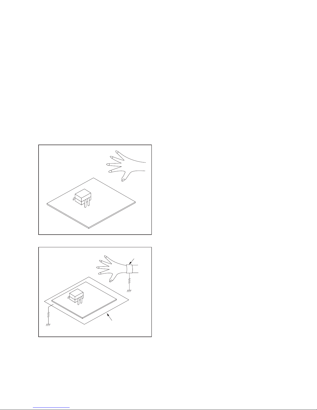
Instructions for Handling Semiconductors
Electrostatic breakdown of the semi-conductors may
occur due to a potential difference caused by
electrostatic charge during unpacking or repair work.
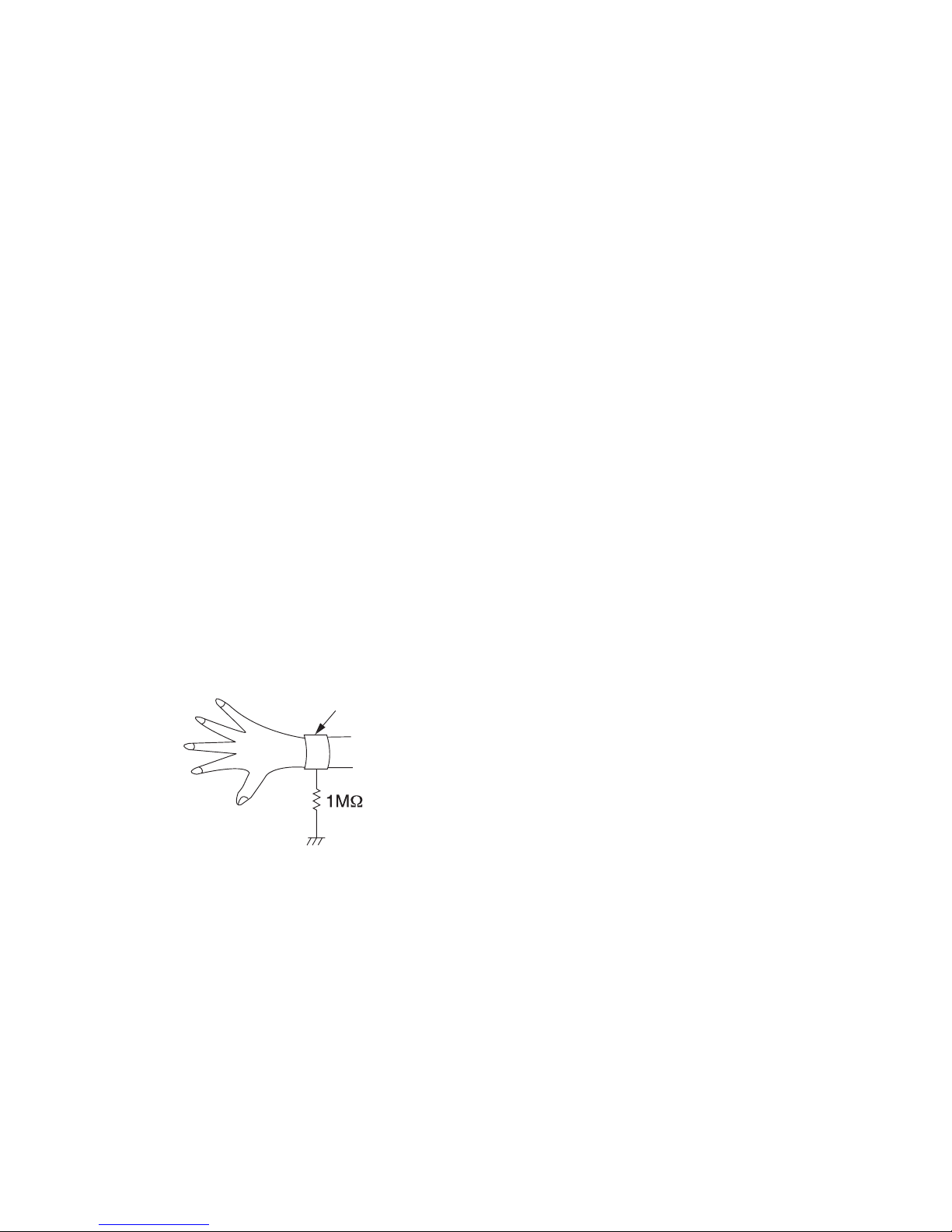
1. Ground for Human Body
Be sure to wear a grounding band (1 MΩ) that is
properly grounded to remove any static electricity that
may be charged on the body.
2. Ground for Workbench
Be sure to place a conductive sheet or copper plate
with proper grounding (1 MΩ) on the workbench or
other surface, where the semi-conductors are to be
placed. Because the static electricity charge on
clothing will not escape through the body grounding
band, be careful to avoid contacting semi-conductors
with your clothing.
<Incorrect>
CBA
Grounding Band
Conductive Sheet or
Copper Plate
1MΩ
1MΩ
<Correct>
CBA
1-5-1 DHDP_SN
HANDLING PRECAUTIONS FOR HDD
CAUTION:
1. SHOCK
a. Exposing HDD to shock may be the biggest
damaging factor. Please note that HDD is easily
damaged even if dropped from any height. Be sure
to place HDD on a shock-absorbent mat. Also, be
careful when transporting HDD.
b. Be careful not to subject HDD to any shock when
tightening screws for HDD replacement.
(Tighten screws manually, not with an electric
driver.)
2. MOISTURE
a. Moisture may also be a damaging factor. HDD is
semiclosed style. Sudden changes in ambient
temperature may cause moisture to form. Monitor
temperature and do not allow moisture to form on
the media surface. Also, when opening HDD
package, do so only after package is at ambient
temperature.
b. After replacing HDD, leave it to reach room
temperature (about 2 hours) for preventing dew
internal condensation, and then work necessary
task such as operation check.
3. STATIC ELECTRICITY
a. After removing HDD or taking replacement HDD
out of the protective bag (the replacement HDD is
packed in a protective bag), place HDD on a
conductive surface. A grounding band should be
worn when handling.
Both the conductive surface and grounding band
should be grounded.
b. Make sure that HDD is placed on main unit
completely and then let go of it, when assembling.
c. Do not put HDD on a packing bag. (for preventing
electrostatic damage)
4. OTHERS
a. Be careful so as not to do the followings.
Otherwise, HDD might be damaged.
- DO NOT disassemble HDD.
- When handling HDD, be sure to hold both sides
securely.
b. HDD should be stored, packed in the protective
bag, in suitable surroundings (i.e., no extreme
changes in temperature to avoid condensation).
c. When transporting HDD, be sure to use the
exclusive packing case (the replacement HDD
carton).
d. Do not stack HDDs.
e. Do not place vertically because HDD is unstable
and easy to fall.
Grounding Band
1-6-1 E4V21DC
CABINET DISASSEMBLY INSTRUCTIONS
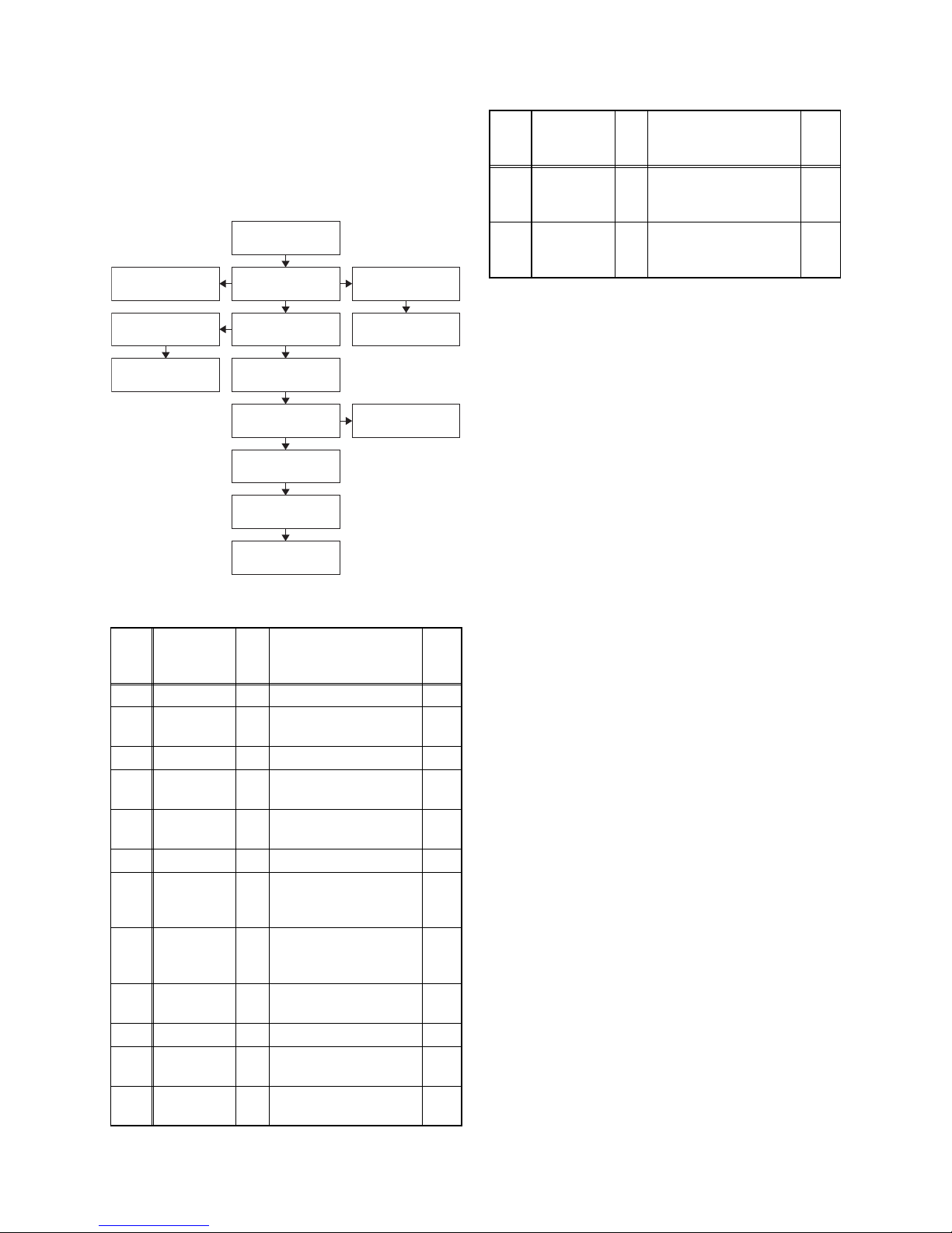
1. Disassembly Flowchart
This flowchart indicates the disassembly steps to gain
access to items to be serviced. When reassembling,
follow the steps in reverse order. Bend, route, and
dress the cables as they were originally.
2. Disassembly Method
Note:
(1) Identification (location) No. of parts in the figures
(2) Name of the part
(3) Figure Number for reference
(4) Identification of parts to be removed, unhooked,
unlocked, released, unplugged, unclamped, or
desoldered.
P = Spring, L = Locking Tab, S = Screw,
CN = Connector
e.g. 2(S-2) = two Screws of (S-2),
2(L-2) = two Locking Tabs of (L-2)
(5) Refer to “Reference Notes.”
Reference Notes
1. CAUTION 1: Locking Tabs (L-1) and (L-2) are
fragile. Be careful not to break them.
2. When replacing the HDD, HDD format is
needed after replacing the HDD. Refer to “HOW
TO FORMAT THE HDD AFTER
REPLACEMENT.”
3. When reassembling, be sure to use the original
screws or specified screws listed in the parts
list.
4. When replacing the BD/HDD Main CBA Unit,
the board and HDD will need to be recognized.
Refer to “BD/HDD MAIN CBA UNIT
REPLACEMENT.”
ID/
Loc.
No.
Part
Fig.
No.
Removal Note
[1] Top Cover D1 5(S-1) ---
[2]
Front
Assembly
D2
4(L-1), 3(L-2), 4(S-2),
CN2105
1
[3] Front CBA D2 --------------- ---
[4]
HDD
Assembly
D3
4(S-3), Connector,
SATA Cable
---
[5]
HDD
Bracket
D4
4(S-4), HDD Damper,
HDD Earth Plate
---
[6] HDD D4 --------------- 2
[7]
BD
Mechanism
Assembly
D5
4(S-5), CN502,
CN6101
---
[8] Rear Panel D6
4(S-6), 2(S-7), (S-8),
(S-9), 2(S-10),
CN8002
3
[9]
Motor DC
Fan
D6 Fan Folder ---
[10] Scart CBA D7 CN3501 ---
[11] Jack CBA D7
3(S-11), CN3002,
CN7400
---
[12]
D-Tuner
CBA
D8 CN5900 ---
[1] Top Cover
[8] Rear Panel
[9] Motor DC Fan
[14] Power
Supply CBA
[12] D-Tuner
CBA
[13] BD/HDD
Main CBA Unit
[3] Front CBA
[11] Jack CBA [10] Scart CBA
[4] HDD
Assembly
[7] BD Mechanism
Assembly
[5] HDD Bracket
[2] Front
Assembly
[6] HDD
[13]
BD/HDD
Main CBA
Unit
D8
3(S-12), CN2804,
CN7401, CN7402,
CN7100
4
[14]
Power
Supply
CBA
D9 3(S-13), Power Holder ---
↓
(1)
↓
(2)
↓
(3)
↓
(4)
↓
(5)
ID/
Loc.
No.
Part
Fig.
No.
Removal Note
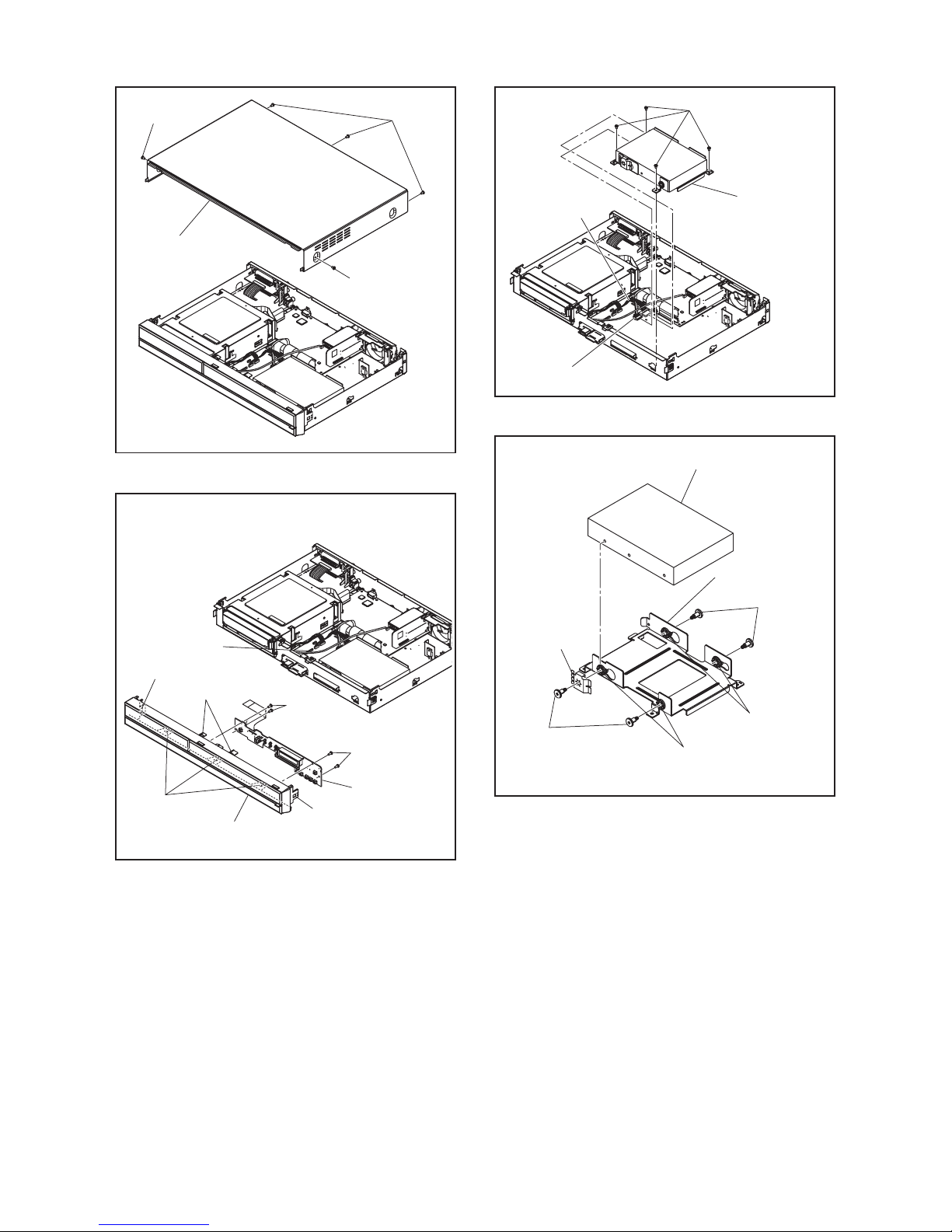
1-6-2 E4V21DC
(S-1)
(S-1)
(S-1)
[1] Top Cover
Fig. D1
(L-1)
(L-2)
CN2105
(L-1)
(S-2)
(S-2)
(L-1)
[2] Front Assembly
[3] Front CBA
Fig. D2
(S-3)
SATA Cable
Connector
[4] HDD
Assembly
Fig. D3
(S-4)
(S-4)
HDD
Earth Plate
HDD Damper
HDD Damper
[5] HDD Bracket
[6] *HDD
* See Reference Note 2.
Fig. D4
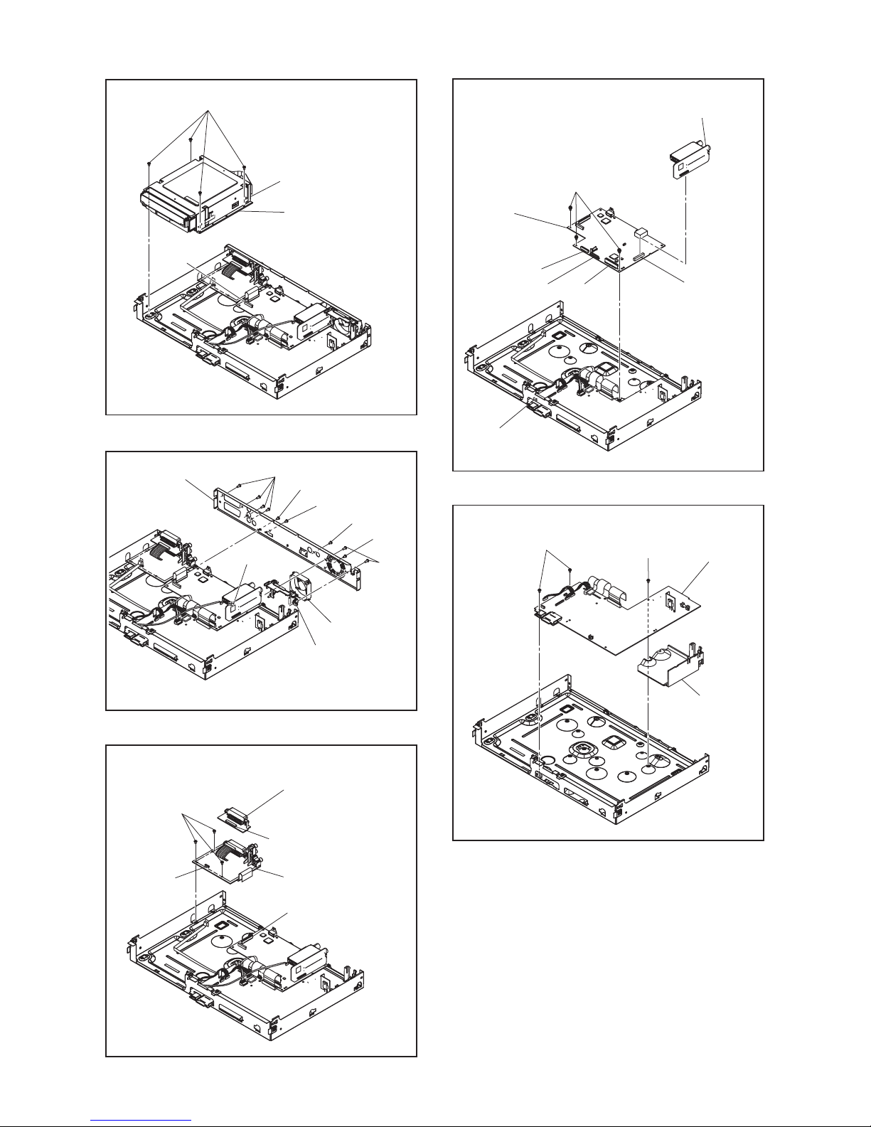
1-6-3 E4V21DC
CN502
CN6101
(S-5)
[7] BD Mechanism
Assembly
Fig. D5
(S-7)
(S-6)
(S-7)
(S-8)
(S-10)
CN8002
Fan Folder
(S-9)
[8] *Rear Panel
[9] Motor
DC Fan
* See Reference Note 3.
Fig. D6
(S-11)
[10] Scart CBA
[11] Jack CBA
CN3501
CN7400
CN3002
Fig. D7
(S-12)
CN5900
CN7402
CN7401
CN7100
CN2804
[12] D-Tuner
CBA
[13] *BD/HDD
Main CBA Unit
* See Reference Note 4.
Fig. D8
Power Holder
(S-13)
(S-13)
[14] Power
Supply CBA
Fig. D9
1-6-4 E4V21DC
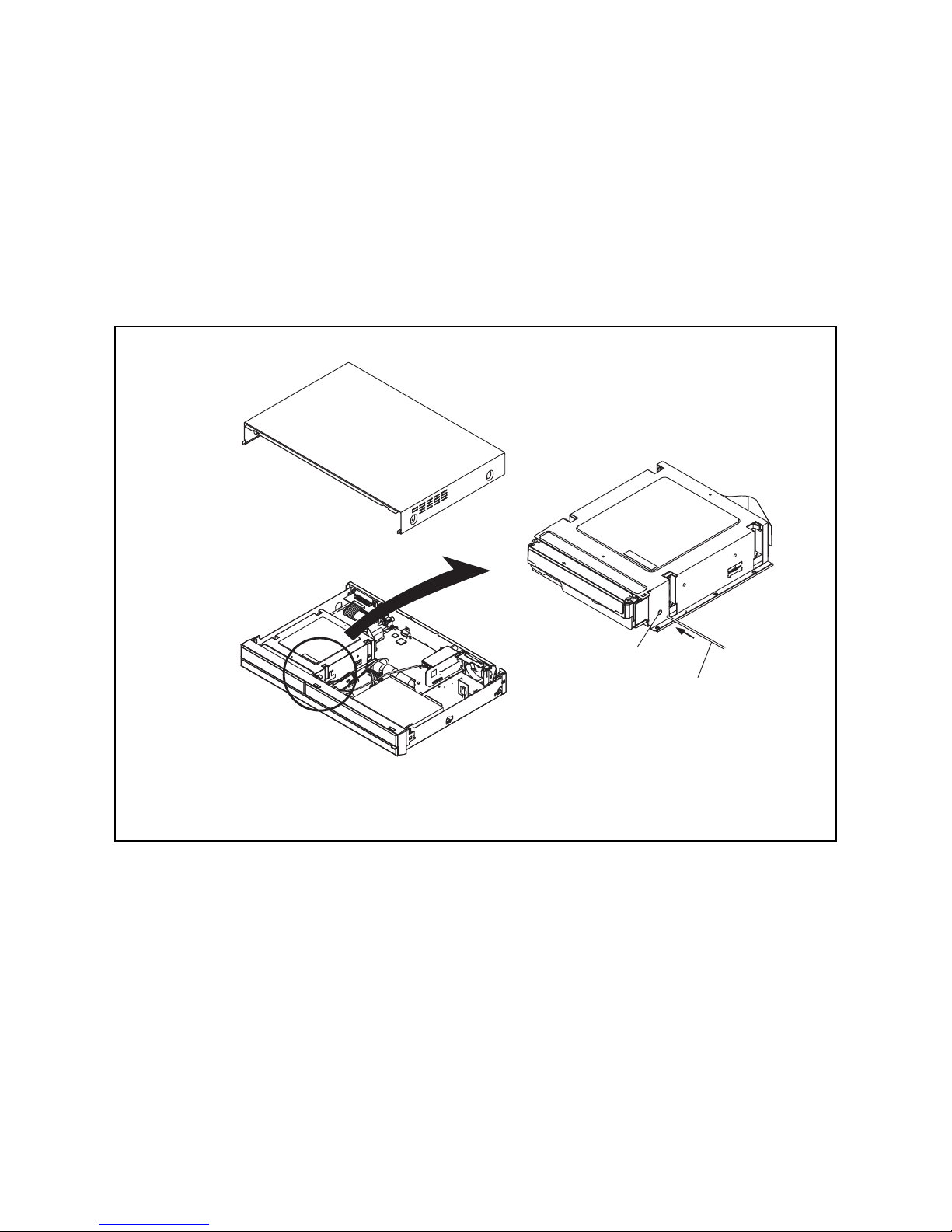
3. How to Eject a Disc
When a disc cannot be removed due to malfunction or when an unplayable disc is inserted, follow the
procedure below to remove the disc.
Procedure A
1. Unplug the AC power cord and then plug it in.
2. Turn the power on by pressing the [ A ] button and the disc tray will open automatically.
Procedure B
1. Remove the Top Cover.
2. Insert a hexagon wrench, etc. into the hole (as shown below) straight and gently until the tray is ejected.
3. Pull the tray out manually and remove the disc.
Hole
Hexagon wrench, etc.

1-7-1 E4V20INT
HOW TO INITIALIZE THE HDD & BLU-RAY DISC RECORDER
To put the program back to the factory-default,
initialize the unit by following the procedure below.
1. Turn the power on.
2. Put the unit into HDD/DISC mode. Remove the
disc on the tray and close the tray.
3. Press [i] (skip up), [1], [2], [3] buttons on the
remote control in this order. The following screen
will be displayed.
* All indicators on LCD light.
4. Press [STOP] button.
5. After the unit is initialized, the power will turn off
automatically.
Note: The titles recorded on HDD will not be deleted.
"*" differ depending on the models.
F/W Name
Version
Region
Pickup
Version Info
: *******
: *.**.**
: *-*
: **
Default Setting : --
Default Setting : STOP End : POWER
LCD/LED Check : OK
1-8-1 E4V20FW
FIRMWARE RENEWAL MODE
How to Prepare a Software Update
Disc (BE F/W, FE F/W)
1. Copy the “****.bin” file to a CD-R/RW or DVD-R/
RW disc.
Note:
• Make sure to use a blank CD-R/RW or DVD-R/
RW disc.
• Copy one file per disc.
How to Update the Unit
(BE F/W, FE F/W)
1. Make sure the unit is not recording or dubbing in
HDD mode, or within 15 minutes a timer recording
begins.
2. Insert the software update disc and close the tray.
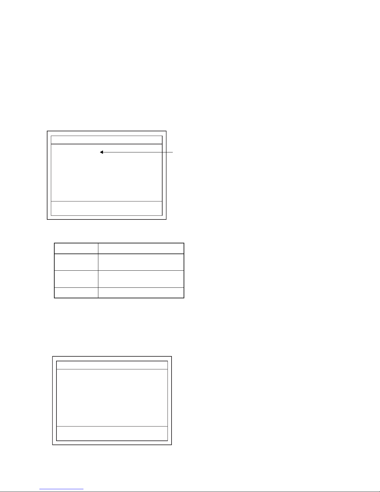
3. When the disc is recognized, the unit enters
Update mode. Fig. a appears on the screen and
Fig. b appears on the LCD.
Fig. a Update Confirmation Screen
Fig. b LCD in Update Mode
4. Select “Yes” to start firmware loading. Fig. c
appears on the screen and Fig. d appears on the
LCD.
Fig. c Firmware Loading Screen
Fig. d LCD during Firmware Loading
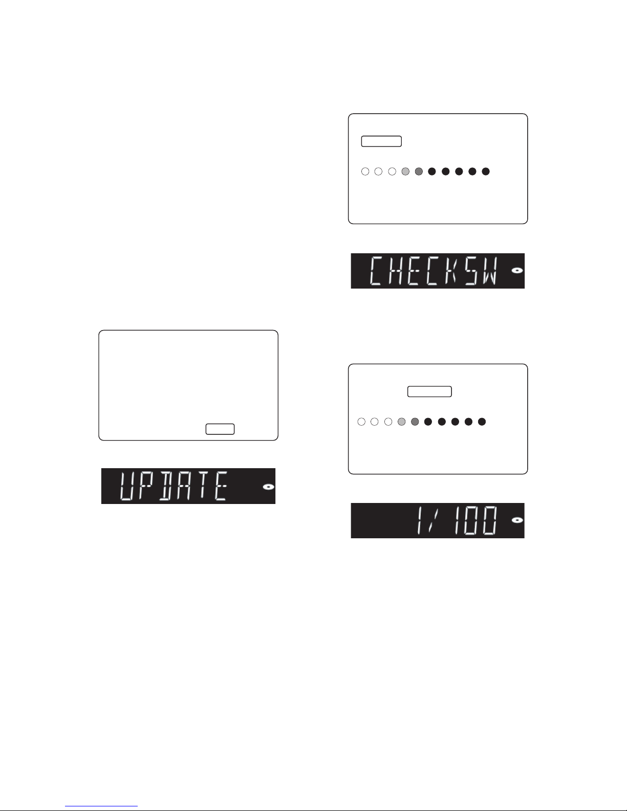
5. The unit will restart automatically then begins
updating. After the unit restarts and the display
becomes available, Fig. e appears on the screen.
The update progress is shown on the LCD.
Fig. e Firmware Updating Screen
Fig. f LCD during Firmware Update
6. Upon completion of firmware update, the unit
restarts and the tray will open automatically.
Remove the disc from the unit.
"*" differ depending on the models.
Software Update
Current Version
Insert Version
Yes
No
Select 'Yes' and press [OK] button to start updating.
Press 'No' to exit software update.
: *.**.**
: *.**.**
Software Update
If you want to exit update, press [RETURN].
Update will continue after screen turns black.
Please wait a moment.
Loading Software...
1. Loading 2. Updating
Software Update
Updating Software...
1. Loading 2. Updating
Please wait for a few minutes.
Do not unplug the AC code or interrupt updating process.
When update is completed unit will automatically turn off.
Update disc will eject after unit automatically turns back on.

1-8-2 E4V20FW
How to Confirm the Firmware
Version
1. Turn the power on.
2. Put the unit into HDD/DISC mode. Remove the
disc on the tray and close the tray.
3. Press [i] (skip up), [1], [2], [3] buttons on the
remote control in this order. The following screen
will be diplayed.
* All indicators on LCD light.
4. To exit this mode, press [STANDBY/ON] button.
"*" differ depending on the models.
F/W Name
Version
Region
Pickup
Version Info
: *******
: *.**.**
: *-*
: **
Default Setting : --
Default Setting : STOP End : POWER
LCD/LED Check : OK
1-9-1 E4V20BDR
BD/HDD MAIN CBA UNIT REPLACEMENT
When replacing the BD/HDD Main CBA Unit, the
board and HDD needs to be matched to one another.
Follow the procedure below to complete the matching
process.
1. Turn the power on.
2. Put the unit into HDD/DISC mode. Remove the
disc on the tray and close the tray.
3. Press [i] (skip up), [3], [1], [0] buttons on the
remote control in this order. The following screen
will be diplayed.
Fig. a Main PCB Change Mode Screen
Description of *1
4. To perform the matching process, press [7], [8], [9]
buttons on the remote control in this order within 3
seconds.
5. After the process completes, the result is
displayed next to the “Status :” on the screen.
(“SUCCESS” at success or “ERR24” at error.)
Fig. b “SUCCESS” Screen
6. Press [STANDBY/ON] button to turn the power off.
7. Unplug the AC cord.
Indication State
Incorrect
Need to complete the matching
process.
OK
Matching process is not
necessary.
NG HDD problem (not connected).
"*" differ depending on the models.
Status
Main PCB Change Mode
: Incorrect
Please input [7]+[8]+[9] key.
F/W Name : ******* Region : *-*
Release Ver. : ****
*
1
"*" differ depending on the models.
Status
Main PCB Change Mode
: SUCCESS
[POWER] : Power Off
F/W Name : ******* Region : *-*
Release Ver. : ****
1-10-1 E4V20HDR
HOW TO FORMAT THE HDD AFTER REPLACEMENT
Note: HDD format is needed after replacing the HDD.
Enter the Self Check Mode and complete HDD
format by following the procedure below.
1. Turn the power on.
2. Put the unit into HDD/DISC mode. Remove the
disc on the tray and close the tray.
3. Press [i] (skip up), [0], [7], [9] buttons on the
remote control in this order. The unit enters Self
Check Mode and the following screen will be
displayed.
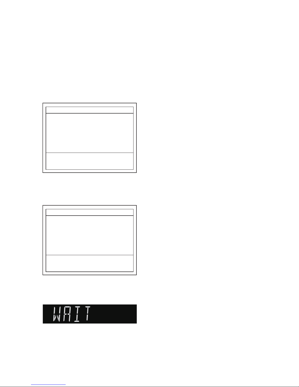
Fig. a Self Check Mode Screen
4. Connection check for loader and HDD starts
automatically. After the self check is completed,
the following screen appears.
Fig. b Screen Display After the Self Check
5. Press [OK] button on the remote control. The
power will turn off. On the LCD, “WAIT” message
is displayed and HDD format begins.
Fig. c LCD during HDD format
Note: Because HDD format is performed in standby
mode, the screen will be black.
6. When format is completed, clock display appears
on the LCD.
Note:
• Make sure the “WAIT” message on LCD has
disappeared before unplugging the AC cord.
• It may take up to 10 or more seconds to complete the
HDD format.
"*" differ depending on the models.
Loader Connect Status
HDD Connect Status
HDD Power On Hours
Self Check
: -: --
: --
F/W Name : *******
Power Off : POWER
Region : *-*
Release Ver. : ****
"*" differ depending on the models.
Loader Connect Status
HDD Connect Status
HDD Power On Hours
Self Check
: SUCCESS
: SUCCESS
: ***
F/W Name : *******
HDD Format
Power Off
: OK
: POWER
This system is unconstruction of the file system.
Region : *-*
Release Ver. : ****
1-11-1 E4V20LD
HOW TO DISPLAY THE LD OPERATING TIME
1. Turn the power on.
2. Put the unit into HDD/DISC mode. Remove the
disc on the tray and close the tray.
3. Press [i] (skip up), [3], [2], [1] buttons on the
remote control in this order. The following screen
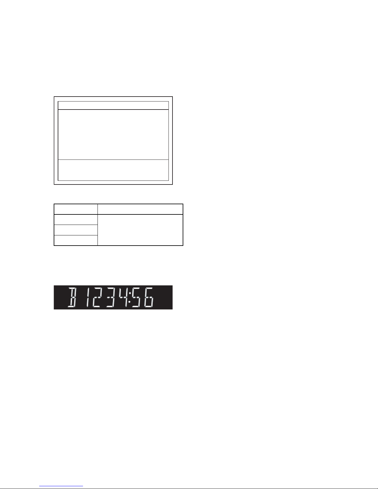
will be displayed.
Fig. a LD Operating Time Screen
Description of Operating Time Screen
4. To select a desired media, use the [UP]/[DOWN]
buttons on the remote control. The operating time
of the selected media will be displayed on the LCD
with a “minute:second” value.
Fig. b Operating Time on LCD (Example of BD)
5. Press [STANDBY/ON] button to exit and to turn
the power off.
6. Unplug the AC cord.
Display Description
Time(BD)
The LD operating time is
displayed. If the value exceeds
9999h59m, <Over!> appears at
the right of the time display.
Time(DVD)
Time(CD)
"*" differ depending on the models.
1: Time(BD)
2: Time(DVD)
3: Time(CD)
LD Operating Time
: * h ** m
: * h ** m
: * h ** m
F/W Name : ******* Region : *-*
Release Ver. : ****

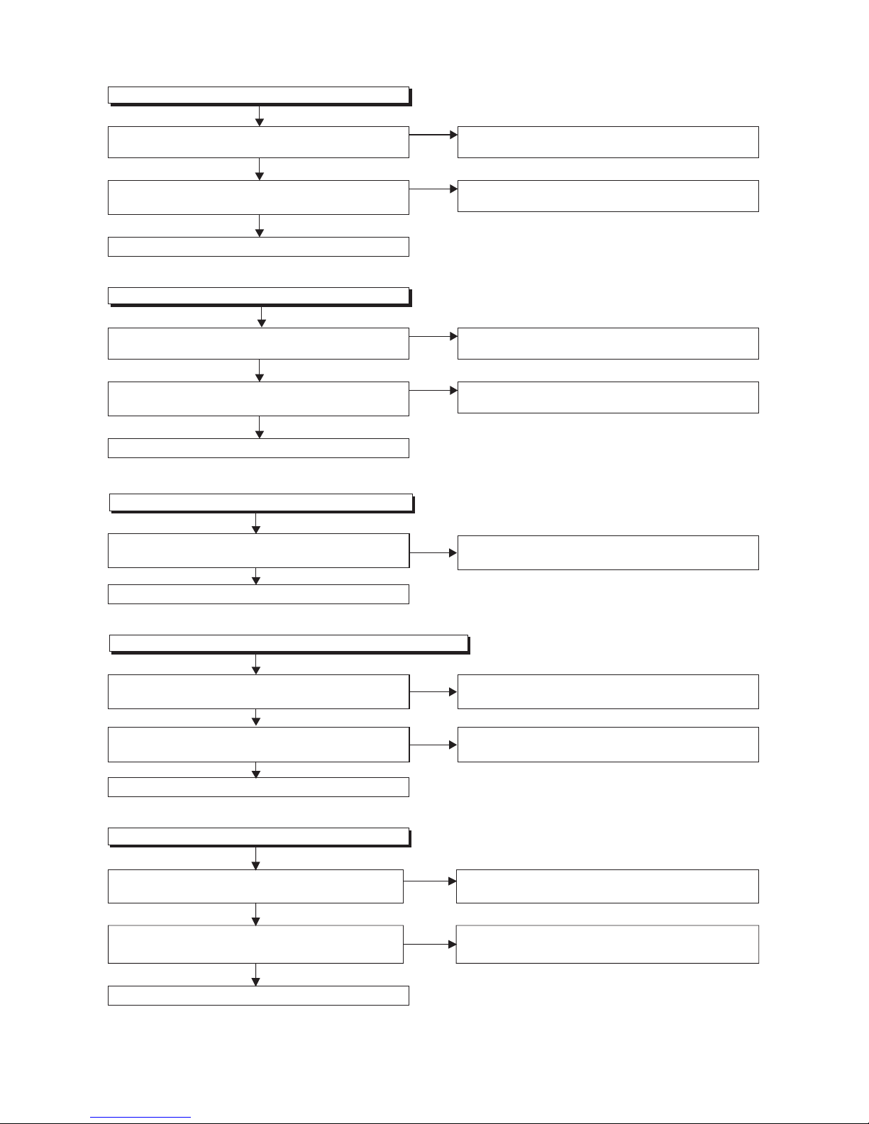
1-12-1 E4V20TR
TROUBLESHOOTING
1 Power Supply Section
Check for load circuit short-circuiting or leak, and
service it
if defective.
FLOW CHART NO.1
The power cannot be turned on.
Is the fuse normal?
Is normal state restored when once unplugged power
cord is plugged again after several seconds.
Check each rectifying circuit of secondary circuit and
service it
if defective.
See FLOW CHART No.2 <The fuse blows out.>
Check for lead or short-circuiting of primary circuit
component and
service it
if defective.
(IC1001, IC1100, Q1001, Q1002, T1001, D1006,
D1007, D1008, D1009, D1010, C1010, R1013)
Ye s
Ye s
No
No
Is the EV+16V line voltage normal?
Ye s
No
FLOW CHART NO.2
The fuse blows out.
After servicing, replace the fuse.
Check the presence that the primary component is
leaking or shorted and service it
if defective.
Check the presence that the rectifying diode or circuit
is shorted in each rectifying circuit of secondary side
and
service it
if defective.
FLOW CHART NO.3
When the output voltage fluctuates.
No
Ye s
Does the secondary side photo coupler circuit operate
normally?
Check the circuit and
service it
if defective. (IC1001,
IC1100, D1001, D1003, D1004, D1005)
Check the circuit and
service it
if defective.
(IC1100, IC1113)
FLOW CHART NO.4
When buzz sound can be heard in the vicinity of power circuit.
Check if there is short circuit on the rectifying diode and the circuit in each rectifying circuit of secondary side, and
service it
if defective. (D1101, D1116, D1117, IC1101, IC1102, IC1104, IC1105, Q2604, Q2651)
No
Ye s
FLOW CHART NO.5
EV+16V is not outputted.
Is approximatery +16V voltage supplied to the cathode
of D1101(D1116, D1117)?
Check D1101, D1116, D1117, C1117 and their
periphery, and
service it
if defective.
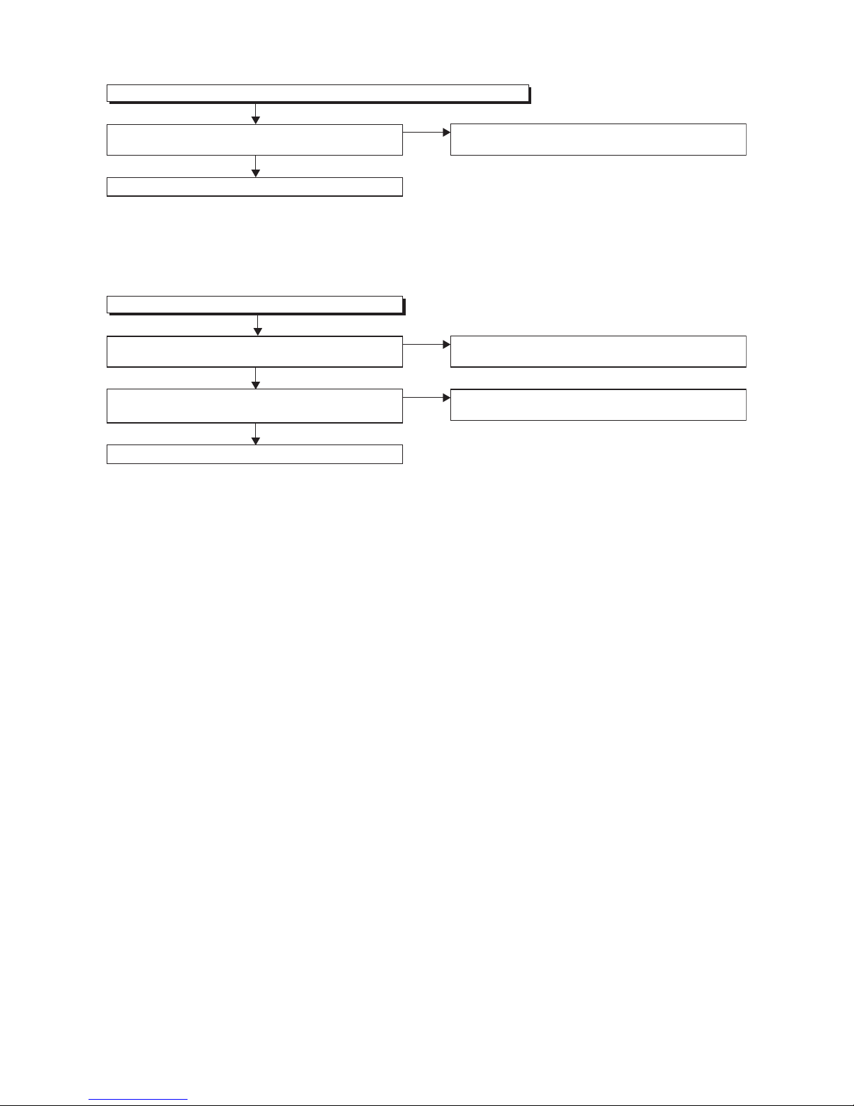
1-12-2 E4V20TR
FLOW CHART NO.6
HDD+12V(FE+12V) is not outputted.
Is approximately +16V voltage supplied to Pin(2) of
IC1102?
Is approximately +5V voltage supplied to Pin(7) of
IC1102?
Refer to "FLOW CHART NO.5"<EV+16V is not
outputted>.
FLOW CHART NO.8
EV+5V(SYS+5V, LCD+5V) is not outputted.
FLOW CHART NO.7
HDD+5V(FE+5V) is not outputted.
FLOW CHART NO.9
P-ON+3.3V(SD+3.3V) is not outputted.
No
Check D1124, DRIVE-SW line and their periphery,
and
service it
if defective.
No
No
No
No
Ye s
Replace IC1102.
Ye s
Is approximately +16V voltage supplied to Pin(2) of
IC1104?
Is approximately +16V voltage supplied to Pin(2) of
IC1105?
Is approximately +16V voltage supplied to Pin(2) of
IC1101?
Is approximately +5V voltage supplied to Pin(7) of
IC1101?
Is approximately +5V voltage supplied to Pin(7) of
IC1104?
Refer to "FLOW CHART NO.5"<EV+16V is not
outputted>.
Refer to "FLOW CHART NO.5"<EV+16V is not
outputted>.
Refer to "FLOW CHART NO.5"<EV+16V is not
outputted>.
Refer to "FLOW CHART NO.5"<EV+16V is not
outputted>.
No
Check D1124, DRIVE-SW line and their periphery,
and
service it
if defective.
Check D1123, 3V3CONT line and their periphery,
and
service it
if defective.
Check D2652, Q2654, Q2658, 1V8CONT line and
their periphery, and
service it
if defective.
No
Ye s
Replace IC1104.
Replace IC1105.
Replace IC1101.
Replace Q2651.
Ye s
Ye s
Ye s
Ye s
FLOW CHART NO.10
P-ON+12V is not outputted.
Is approximately 14V voltage supplied to the collector
of Q2651?
Is approximately 13V voltage supplied to the base of
Q2651?
No
Ye s
No
Ye s
1-12-3 E4V20TR
FLOW CHART NO.11
P-ON+5V(USB+5V, EV+5V-AV) is not outputted. (EV+5V is outputted normally.)
Is approximately +4.5V voltage supplied to the base of
Q2605?
FLOW CHART NO.12
EV+3.9V is not outputted.
No
Check Q2655, POWER-SW line and their periphery,
and
service it
if defective.
Ye s
Replace Q2605.
Is approximately +5V voltage supplied to the collector
of Q2604?
Is approximately +4.5V voltage supplied to the base of
Q2604?
Refer to "FLOW CHART NO.8"<EV+5V(SYS+5V,
LCD+5V) is not outputted>.
No
Check R2605, R2606 and their periphery, and
service
it
if defective.
No
Ye s
Replace Q2604.
Ye s
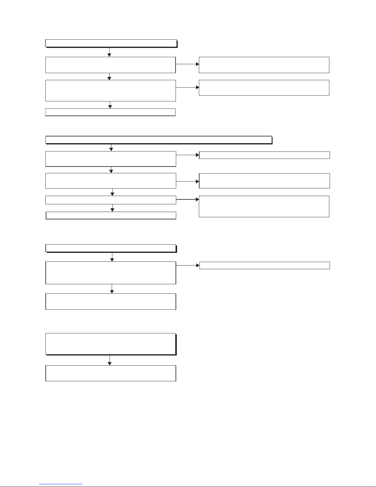
1-12-4 E4V20TR
2 BD/HDD Section
FLOW CHART NO.3
FLOW CHART NO.1
Check the line between the
RS
3701
(remote control
receiver)
and the
Pin(41) of IC2701,
and service it if
detective.
FLOW CHART NO.2
No operation is possible from the remote control unit.(Operation is possible from the unit.)
Replace the RS
3701
(remote control receiver) or remote
control unit.
Is the "L" pulse sent out Pin(1) of RS3701 (remote control
receiver) when the remote control unit is activated?
Is the "L" pulse inputted to the Pin(41) of IC2701?
Replace IC2701.
Is approximately +5V voltage supplied to Pin(2) of
RS3701 (remote control receiver) ?
Ye s
No
Check LCD+5V line and service it if defective.
No
No
Ye s
Ye s
Ye s
No
The key operation is not functioning.
Are the contact point and the installation state
of the key switches (SW3701-SW3707) normal?
When pressing each switches (SW3701-SW3707),
do the voltage of Pin(46, 47, 48, 55) of IC2701
decrease?
Check the switches (SW3701-SW3707) and their
periphery, and service it if detective.
No
Re-install the switches (SW3701-SW3707) correctly or
replace the poor switch.
Replace IC2701.
Ye s
Ye s
The disc tray cannot be opened and closed.
Is the normal control voltage inputted to Pin(47) of
IC2701? Refer to "FLOW CHART NO.1" <The key
operation is not functioning.>
Replace the BD Mechanism Assembly or BD/HDD
Main CBA Unit.
Replace the "OPEN/CLOSE" switch (SW3707).
No
FLOW CHART NO.4
Replace the BD Mechanism Assembly or BD/HDD
Main CBA Unit.
There is [No Disc] indication.
Both picture and sound do not operate normally.
 Loading...