

INSTALLATION AND
OPERATION MANUAL
Gas Pulse Combustion
Hydronic Heating Boiler (PHW)
Serial/National
Board #
Model
Fulton Order
Sold To
Job Name
Date
PHW-IOM-2013-0214


PHW-IOM-2013-0214 TABLE OF CONTENTS
Introduction 1-1
Overview .............................................................................................................. 1-2
Warnings & Cautions ............................................................................................1-2
Disclaimers and Local Codes ................................................................................1-2
Installation 2-1
Product Overview ................................................................................................. 2-2
Review Shipment Contents .................................................................................. 2-2
Placement & Rigging ........................................................................................... 2-3
Clearances and Serviceability ..............................................................................2-5
Install Isolation Mounts ....................................................................................... 2-5
HOW TO INSTALL ELASTOMER CUBE ISOLATION MOUNTS ........................................................25
HOW TO INSTALL SPRING ISOLATION MOUNTS .........................................................................26
HOW TO INSTALL SEISMIC SPRING ISOLATION MOUNTS...........................................................27
Install Boiler Trim .................................................................................................2-8
Water Chemistry Requirements ...........................................................................2-8
Install Water Piping .............................................................................................. 2-9
Install Condensate Drain .................................................................................... 2-11
INSTALL CONDENSATE DRAIN PIPING .....................................................................................212
Install pH Neutralization Kit ...............................................................................2-12
Install Gas Piping ................................................................................................2-14
Install Field Wiring .............................................................................................2-14
Air Intake Supply Piping Installation Preparation .............................................. 2-15
CEMENTING JOINTS ...................................................................................................................216
Install Intake Mu er ......................................................................................... 2-17
Preparing to Install Exhaust Vent Piping ............................................................2-17
Exhaust Mu er Installation ..............................................................................2-18
Air Intake & Exhaust Piping Requirements for the Pulse Boiler ........................2-19
Air Intake Supply and Exhaust Vent Installation ...............................................2-20
Vertical Vent Flashing and Installation .............................................................. 2-21
Vertical Vent Termination ..................................................................................2-21
Horizontal Installation Wall Penetrations ......................................................... 2-24
Wall Thimble Installation .................................................................................. 2-24
Horizontal Vent Termination ............................................................................. 2-25
After Installation/Prior to Start-Up .................................................................... 2-26
Installation Checkpoints ...................................................................................2-28
Testing Ignition Safety Shut O ........................................................................2-28
Measure Gas Flow Rate ..................................................................................... 2-28
TO CORRECT INPUT ADJUST GAS PRESSURE REGULATOR ....................................................229
Rating the Boiler ................................................................................................2-29
To Check for High Gas Pressure ..........................................................................2-29
For High Gas Pressure Installations Using Fisher Regulators .............................2-29
Before Leaving the Installation ......................................................................... 2-30
Operation 3-1
Before Start Up .....................................................................................................3-2
Start Up ................................................................................................................3-2
LINKAGE ADJUSTMENT FOR PULSE MODULATED BOILERS.......................................................33
IF THE BOILER DOESN’T START ..................................................................................................35
Sequence of Operation for Modulated Pulse Hydronic Boilers ............................ 3-6
General Operation of the Boiler ........................................................................... 3-6
Programming Instructions for the SOLA Control ................................................. 3-6
CHANGING/TESTING SOLA HIGH LIMIT SETPOINT ..................................................................310
VERIFYING CHANGES TO HIGH LIMIT SETPOINT .....................................................................310
ACCESSING LOCKOUT HISTORY AND CLEARING LOCKOUTS .....................................................311
PROCEDURE FOR REMOTE FIRING RATE USING A 420MA SIGNAL SINGLE BOILER ...........312
PROCEDURE FOR REMOTE SETPOINT USING A 420MA SIGNAL SINGLE BOILER ................313
PROCEDURE FOR LEAD/LAG WITH OUTDOOR RESET WITH MULTIPLE BOILERS ....................314
SINGLE BOILER OUTDOOR RESET PROGRAMMING ..................................................................318
Third Party SOLA Control ....................................................................................3-21
LEAD/LAG OUTDOOR RESET CONFIGURATION USING COMMUNICATION PORT 2 ..................321
STAND ALONE BOILERS CONTROLLED BY A THIRD PARTY CONTROL ......................................321
GATEWAYS .................................................................................................................................321
Maintenance 4-1
General ................................................................................................................. 4-2
Daily Maintenance and Inspection Schedule ......................................................4-2
Monthly Maintenance and Inspection Schedule .................................................4-2
Annual Maintenance and Inspection Schedule ................................................... 4-3
After All Repairs and Maintenance ...................................................................... 4-4
Troubleshooting ...................................................................................................4-5
Reviewing Diagnostics on SOLA Control ..............................................................4-6
TAKING SCREEN SHOTS................................................................................................................47
Warranty & Parts 5-1
Standard Warranty for Fulton Pulse Boilers
with Carbon Steel Exhaust Pipes .......................................................................... 5-2
Standard Warranty for Fulton Pulse Boilers
with Duplex Stainless Steel Exhaust Pipes ...........................................................5-3
Parts ..................................................................................................................... 5-4
Questions? Call (315) 298-5121, or visit us online at www.fulton.com
0-1

TABLE OF CONTENTS PHW-IOM-2013-0214
0-2
© The Fulton Companies 2013

INTRODUCTION
INTRODUCTION
INSTALLATION
1
2
OPERATION
MAINTENANCE
WARRANTY & PARTS
3
4
5
Questions? Call (315) 298-5121, or visit us online at www.fulton.com
1-1

INTRODUCTION PHW-IOM-2013-0214 SECTION 1
Overview
Prior to shipment, the following inspections and tests are
made to ensure the highest standards of manufacturing for
our customers:
§ Material inspections
§ Manufacturing process inspections
§ American Society of Mechanical Engineers (ASME)
welding inspection
§ ASME hydrostatic test inspection
§ Electrical components inspection
§ Operating test
§ Final engineering inspection
§ Crating inspection
This manual is provided as a guide to the correct operation
and maintenance of your Fulton equipment, and should be
read in its entirety and be made permanently available to the
sta responsible for the operation of the boiler. It should not,
however, be considered as a complete code of practice, nor
should it replace existing codes or standards which may be
applicable. Fulton reserves the right to change any part of
this installation, operation and maintenance manual.
Installation, start-up, and maintenance of this equipment
can be hazardous and requires trained, quali ed installers
and service personnel. Trained personnel are responsible
for the installation, operation, and maintenance of this
product, and for the safety assurance of installation,
operation, and maintenance processes. Do not install,
operate, service or repair any component of this
equipment unless you are quali ed and fully understand
all requirements and procedures. Trained personnel
refers to those who have completed Fulton Service School
training speci c to this product.
Warnings & Cautions
WARNINGS and CAUTIONS appear in various chapters of this
manual. It is critical that all personnel read and adhere to all
information contained in WARNINGS and CAUTIONS.
§ WARNINGS must be observed to prevent serious injury
or death to personnel.
§ CAUTIONS must be observed to prevent damage
or destruction of equipment or loss of operating
e ectiveness.
All Warnings and Cautions are for reference and guidance
purposes, and do not substitute for required professional
training, conduct, and strict adherence to applicable
jurisdictional/professional codes or regulations.
Disclaimers and Local Codes
Installation of the equipment shall conform to all the
requirements or all national, state and local codes established
by the authorities having jurisdiction or, in the absence
of such requirements, in the US to the National Fuel Gas
Code ANSI Z2231/NFPA 54 latest edition, and the speci c
instructions in this manual. Authorities having jurisdiction
should be consulted prior to installation.
When required by local codes, the installation must conform
to the American Society of Mechanical Engineers Safety Code
for Controls and Safety Devices for Automatically Fired Boilers
(ASME CSD-1).
The boiler heat exchanger is manufactured and stamped
in accordance with ASME Boiler and Pressure Vessel Code,
Section IV for a maximum allowable working pressure of 160
psig. Maximum allowable working temperature varies by
design (210 F for duplex; 240 F for carbon).
When working on this equipment, observe all warnings,
cautions, and notes in literature, on stickers and labels, and
any additional safety precautions that apply. Follow all safety
codes and wear appropriate safety protection. Follow all
jurisdictional codes and consult any jurisdictional authorities
prior to installation.
1-2
© The Fulton Companies 2013

INSTALLATION
INTRODUCTION
INSTALLATION
1
2
OPERATION
MAINTENANCE
WARRANTY & PARTS
3
4
5
Questions? Call (315) 298-5121, or visit us online at www.fulton.com
2-1
INSTALLATION PHW-IOM-2013-0214 SECTION 2
This Boiler is a Direct Vent Boiler for
Installations on Non-Combustible Floors Only
Fulton Gas Fired
Pulse Combustion Boiler
Manufactured by
Fulton Heating Solutions, Inc.
Pulaski, New York 13142
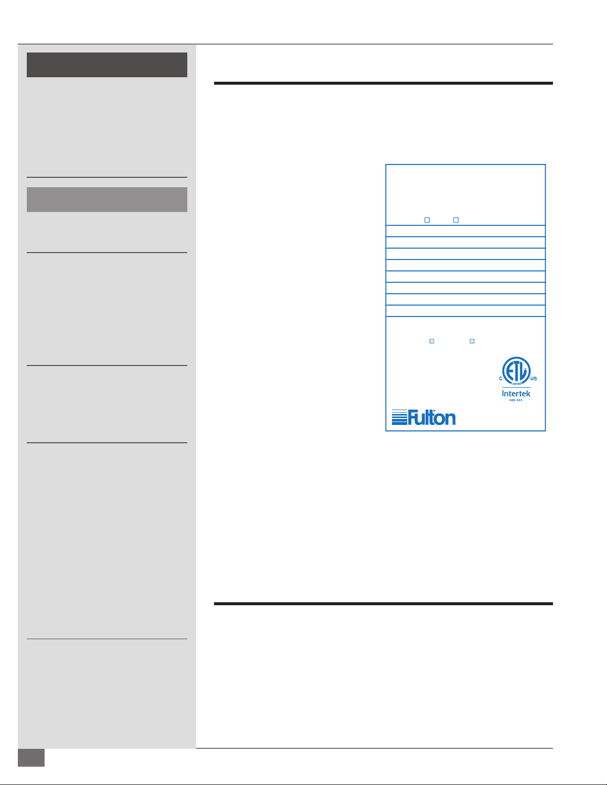
Maximum Gas Supply Pressure: 14 Inches W.C.
Minimum Permissible Gas Supply Pressure for Purpose of
Input Adjustment: 7 Inches W.C. 11 Inches W.C.
Electrical Ratings: 120 V/60 Hz/Less than 15 Amps
Conforms to ANSI Std. Z21.13 __________
Certified to CSA Std. 4.9__________
Wall Thickness Through Which Vent System May
Be Installed: 3
1
/4 Inches Min. / 20 Inches Max.
Minimum Clearance to Combustibles:
1 Inch (Sides) / 24 Inches (Top, Front & Rear)
Type of Gas:
Natural Propane
Boiler Model No.
Boiler National Board No.
Year
Min. BTU Input/Hr. Min. BTU Output/Hr.
Max. BTU Input/Hr. Max. BTU Output/Hr.
Design Pressure PSI
Mimimum Relief Valve Capacity: Pounds/Hr.
Manifold Gas Pressure: Inches W.C.
! WARNING
All information in this manual is for
reference and guidance purposes,
and does not substitute for required
professional training, conduct,
and strict adherence to applicable
jurisdictional/professional codes and
regulations.
4 CAUTION
This boiler is certi ed for indoor
installation only.
This boiler is not designed for use in
systems where water is continuously
replenished. Mineral build-up may
occur on the heat transfer surfaces
and result in overheating and
possible heat exchange failure. The
warranty is valid for closed loop
systems only.
Fulton cannot be held responsible
for the selection, engineering,
installation, or sizing of any
additional equipment or components
of the hydronic heating system.
This boiler, when installed in
conjunction with a refrigeration
system, must be installed so that the
chilled medium is piped in parallel
with the boiler with appropriate valves
to prevent the chilled medium from
entering the boiler. If the boilers are
connected to heating coils located in
air handling units where they may be
exposed to refrigerated air circulation,
such boiler piping systems must be
equipped with ow control valves or
other automatic means to prevent
gravity circulation of the boiler water
during the cooling cycle.
2-2
Product Overview
Prior to the performance of installation, operation, or maintenance procedures,
personnel should become familiar with the equipment (Table 1, Figures 1 and 2)
and its components.
The Fulton Pulse combustion hydronic boiler is an automatic gas red, direct
vent boiler. This boiler utilizes pulse
combustion principle. It does not
have conventional burner controls
or chimney. The combustion
components are of integral design
with the heat exchanger. Each boiler
is built to ASME and CSD-1 Codes,
hydrostatically tested, test red, and
shipped as a complete packaged
unit.
All installations must be in
accordance with the American
National Standard “National Fuel
Gas Code,” latest edition, and with
the requirements of local utilities or
other authorities having jurisdiction.
Such applicable requirements
take precedence over the general
instructions herein.
Since an external electrical source
is utilized, the boiler must be
electrically grounded in accordance
FIGURE 1 PULSE BOILER PLATE
with the National Electrical Code,
ANSI/NFPA 70-latest edition.
In some cases the approval authority may insist that the installation conform to
the American Society of Mechanical Engineers ASME safety standard for controls
and safety devices for automatically red boilers, or CSD-1. In Canada, gas
installations must be in accordance with the current CAN/CGA B149.1 and .2 and/
or local codes. Electrical installations must be installed in accordance with the
current CSA C22.1 Canadian Electrical Code and/or local codes.
Review Shipment Contents
Your Fulton Pulse Boiler shipment should be fully reviewed upon receipt. The
following are standard and accessory items that may be included with your
shipment.
The customer should also examine the equipment for any shipment damage.
It is the responsibility of the installer to ensure all parts supplied with the
equipment are tted in a correct and safe manner.
© The Fulton Companies 2013

SECTION 2 PHW-IOM-2013-0214 INSTALLATION
} STANDARD TRIM
The following items are standard trim for Fulton Pulse Combustion Hydronic
Boilers:
§ Microprocessor Based Control - 120 volt with built-in operating and high
limit controls, and separately wired dual element sensor
§ Low Water Cuto (Probe Type)
§ Control Panel Completely Wired with Diagram
§ Gas Pressure Switches
§ Spark Ignition
§ Factory-Assembled and Mounted Fuel Train
§ Flame Rod
} PACKAGED SEPARATELY
Included with and packaged separately with each boiler are the following
components:
§ ASME Pressure Relief Valve
§ Pressure-Temperature Gauge
§ Air Intake Pipe Adaptor
§ Installation, Operation, and Maintenance Manual
§ Elastomer Coated Fiberglass Cubes or Springs For Mounting
§ Gas and Water Flex Connectors
§ Intake and Exhaust Mu ers
§ 1 Can Touch-up Paint
} OTHER ACCESSORIES
Other items that may be included are:
§ Condensate Drain - one condensate drain kit can accommodate the
condensate from up to 12 MM BTUs.
§ PH Neutralization Kit
! WARNING
All information in this manual is for
reference and guidance purposes,
and does not substitute for required
professional training, conduct, and strict
adherence to applicable jurisdictional/
professional codes and regulations.
Competent personnel in accordance
with all applicable local codes should
carry out the installation of the Fulton
equipment. All state and jurisdictional
codes beyond the scope of the applicable
ASME Boiler and Pressure Vessel Codes,
for its corresponding classi cation, should
be followed in all cases. Jurisdictional
authorities must be consulted prior to
installation.
A competent rigger experienced in
handling heavy equipment should handle
rigging your equipment into position.
The equipment must be installed on a
non-combustible surface.
Failure to provide required and safe
access to the equipment could impede
commissioning and maintenance.
Service technicians are instructed not to
commence commissioning if hazardous
conditions exist.
Placement & Rigging
Proper placement of your Fulton product is essential. Correct placement is the
rst step to trouble-free installation, operation, and maintenance.
Adhere to the following for placement and rigging:
1. Check building speci cations for permissible oor loading. Use Table 1 for
unit reference.
2. Conform to all the requirements of all national, state and local codes
established by the authorities having jurisdiction and/or the U.S. to the
National Fuel Gas Code, latest edition. Authorities having jurisdiction
should be consulted before installations are made. Where required by local
codes, the installation must conform to American Society of Mechanical
Engineers Safety Code for Controls and Safety Devices for Automatically
Fired Boilers (ASME CSD-1).
3. Since an external electrical source is utilized, the boiler, when installed,
must be electrically ground in accordance with the National Electric Code,
Questions? Call (315) 298-5121, or visit us online at www.fulton.com
Failure to provide proper minimum
clearances between equipment and
combustible materials may result in re.
4 CAUTION
Do not allow weight to bear on equipment
components to prevent damage.
2-3
INSTALLATION PHW-IOM-2013-0214 SECTION 2
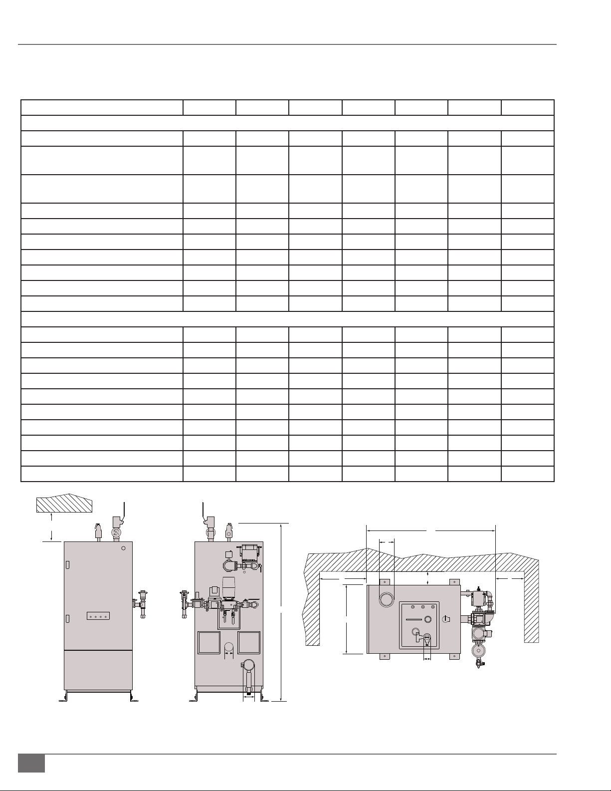
Back View
Front View
Top View
A
C
D
B
G
E
H
F
F
I J
TABLE 1 - BOILER DIMENSIONS AND OPERATING REQUIREMENTS
Model PHW 300 500 750 1000 1400 2000
Speci cations
Input BTU/Hr 300,000 500,000 750,000 1,000,000 1,400,000 2,000,000
Nat. Gas consumption @ rated
capacity
Propane Consumption @rated
capacity
Electrical Requirements 120V/60/1 4.2/0.6 4.2/0.6 4.2/0.6 4.2/0.6 4.2/0.6 10/.75
(Amps: Max/Run)
MAWP PSI 160 160 160 160 160 160
Water Content Gal 34 34 42 42 80 75
Dry Weight LB 1395 1395 1800 1800 2230 2900
Operating Weight LB 1680 1680 2150 2150 3195 3500
Dimensions
A. Boiler Width IN 27.5 27.5 27.5 27.5 33.6 33.6
B. Overall Boiler Height IN 71.25 71.25 83.2 83.2 88.1 89
C. Overall Boiler Depth IN 53.25 53.25 51.3 51.3 62.6 70.1
D. Exhaust Outlet Diameter IN 4 4 4 4 4 6
E. Air Inlet Diameter IN 3 3 4 4 4 6
F. Water Inlet/ Outlet Diameter IN 2 2 2 2 2.5 4 Flanged
G. Min. Clearance to Ceiling IN 24 24 24 24 24 24
H. Min. Clearance to Either Side Wall IN 1 1 1 1 1 1
I. Min. Clearance in Front of Boiler IN 36 36 36 36 36 36
J. Min. Clearance Behind Boiler IN 24 24 24 24 24 24
FT3/Hr 300 500 750 1000 1400 2000
FT3/Hr 120 200 300 400 560 720
240V/60/1 2.1/0.3 2.1/0.3 2.1/0.3 2.1/0.3 2.1/0.3 5/0.4
BAR 4.1/11.0 4.1/11.0 4.1/11.0 4.1/11.0 4.1/11.0 4.1/11.0
FIGURE 2 -PULSE COMBUSTION HYDRONIC BOILER
2-4
© The Fulton Companies 2013

SECTION 2 PHW-IOM-2013-0214 INSTALLATION
American National Standards Institute (ANSI) National Fire Protection
Association (NFPA) 70, latest edition.
4. Install so that all system components are protected from water (dripping,
spraying, rain, etc.) during boiler operation and service.
5. Install on a level, non-combustible surface in the vertical position. Concrete
is strongly recommended.
6. Provide combustion and ventilation air in accordance with applicable
provisions of local building codes or: USA – NFPA 54/ANSI Z223.1, Section
5.3, Air for Combustion and Ventilation.
7. Locate the boiler so that the air supply and exhaust piping between
the boiler and outside wall/roof are within length or pressure drop
requirements. See Clearances and Serviceability section of this manual.
Clearances and Serviceability
Adhere to the following for clearances and serviceability:
1. All local and national codes (NFPA, ANSI, UL, ETL, ASME, CSA) must be
followed for proper clearances and serviceability for your boiler or heater.
Authorities having jurisdiction should be consulted before installations are
made.
! WARNING
Do not install this boiler in an uncontrolled
environment where condensate will be
subject to freezing temperatures.
4 CAUTION
Do not install this boiler on carpeting.
Install boiler such that gas ignition system
components are protected from water
(dripping, spraying, rain, etc.) during boiler
operation and service.
2. Appropriate front, back, side and top clearances must be maintained
(Figure 2, Table 1). This will allow access around the equipment to facilitate
maintenance and a safe work environment. An 1 inch (25.4 mm) side
clearance is acceptable between boilers. Custom con gurations may not
allow 1 inch (25.4 mm) side clearance.
3. Ensure all labels on the boiler will be fully visible for maintenance and
inspection.
Install Isolation Mounts
All pulse combustion boilers must be installed with vibration isolators. No
pulse combustion boiler shall be lagged directly to the concrete oor due to
the transfer of vibration. For installations near “sensitive” areas such as o ces,
classrooms, or hospital rooms, spring mounts - which t under the corner of each
boiler - must be used instead of the cubes.
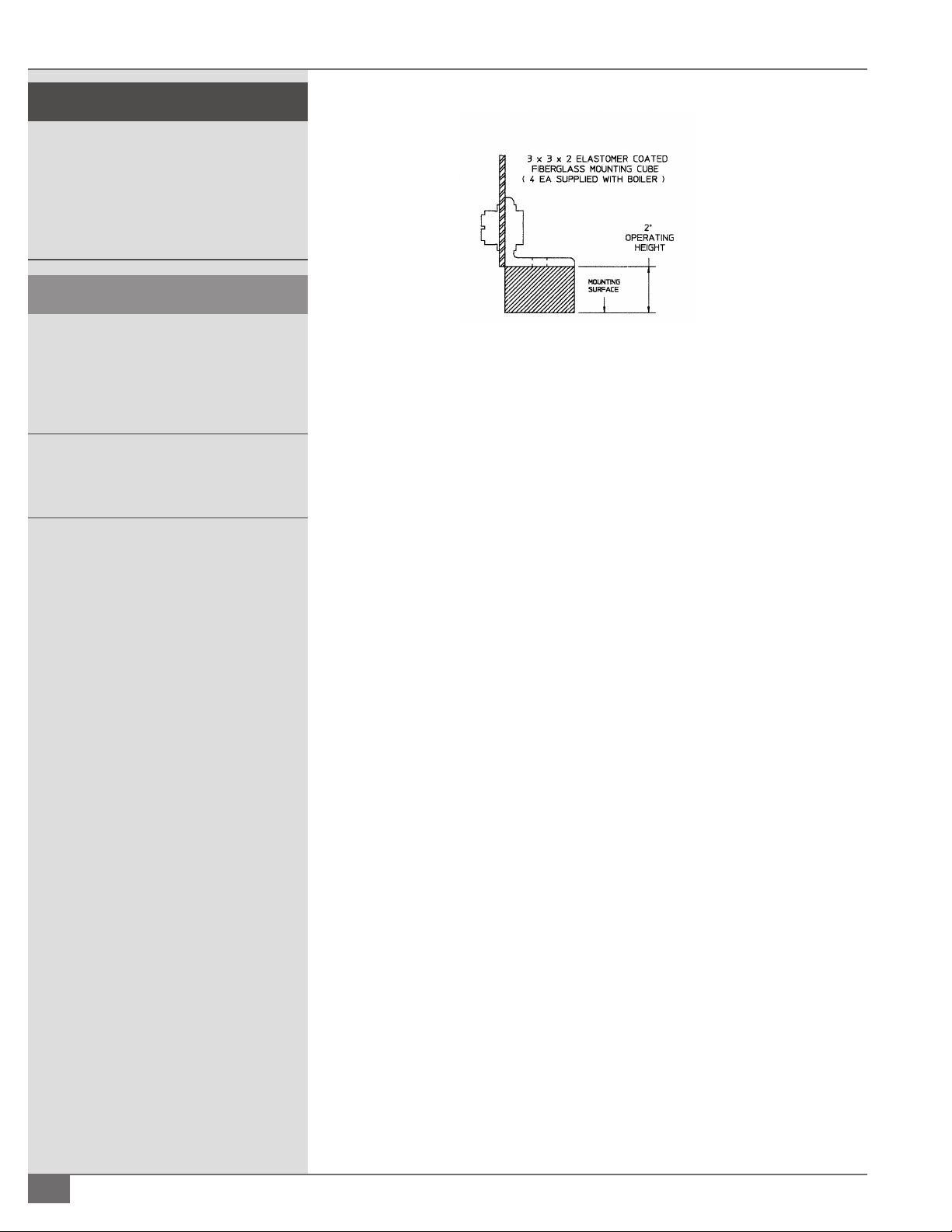
¡ How to Install Elastomer Cube Isolation Mounts
Adhere to the following for elastomer cube isolation mounts (see Figure 3):
1. Locate in the box of trim shipped with each Pulse boiler the 4 elastomer
cubes (3” x 3” x 2”) used for vibration isolation.
2. Insert these cubes under each foot of the boiler.
Questions? Call (315) 298-5121, or visit us online at www.fulton.com
2-5
INSTALLATION PHW-IOM-2013-0214 SECTION 2
! WARNING
All information in this manual is for
reference and guidance purposes,
and does not substitute for required
professional training, conduct, and strict
adherence to applicable jurisdictional/
professional codes and regulations.
4 CAUTION
Do not attempt to move the boiler laterally
while it is supported on isolators. Bent or
broken leveling bolts or springs, or damage
to the neoprene bottom spring cap could
result.
Do not install the boiler in an uncontrolled
environment where the condensate will be
subject to freezing temperatures.
NOTE: ´ Flex connectors must be installed on the gas supply, water inlet and
water outlet lines. Spring loaded pipe hangers should be used on the air
inlet and the ue gas vent.
NOTE: ´ Contact your Fulton Representative for vibration isolation packages
designed speci cally for your application.
FIGURE 3 - INSTALLING ELASTOMER CUBE ISOLATION MOUNTS
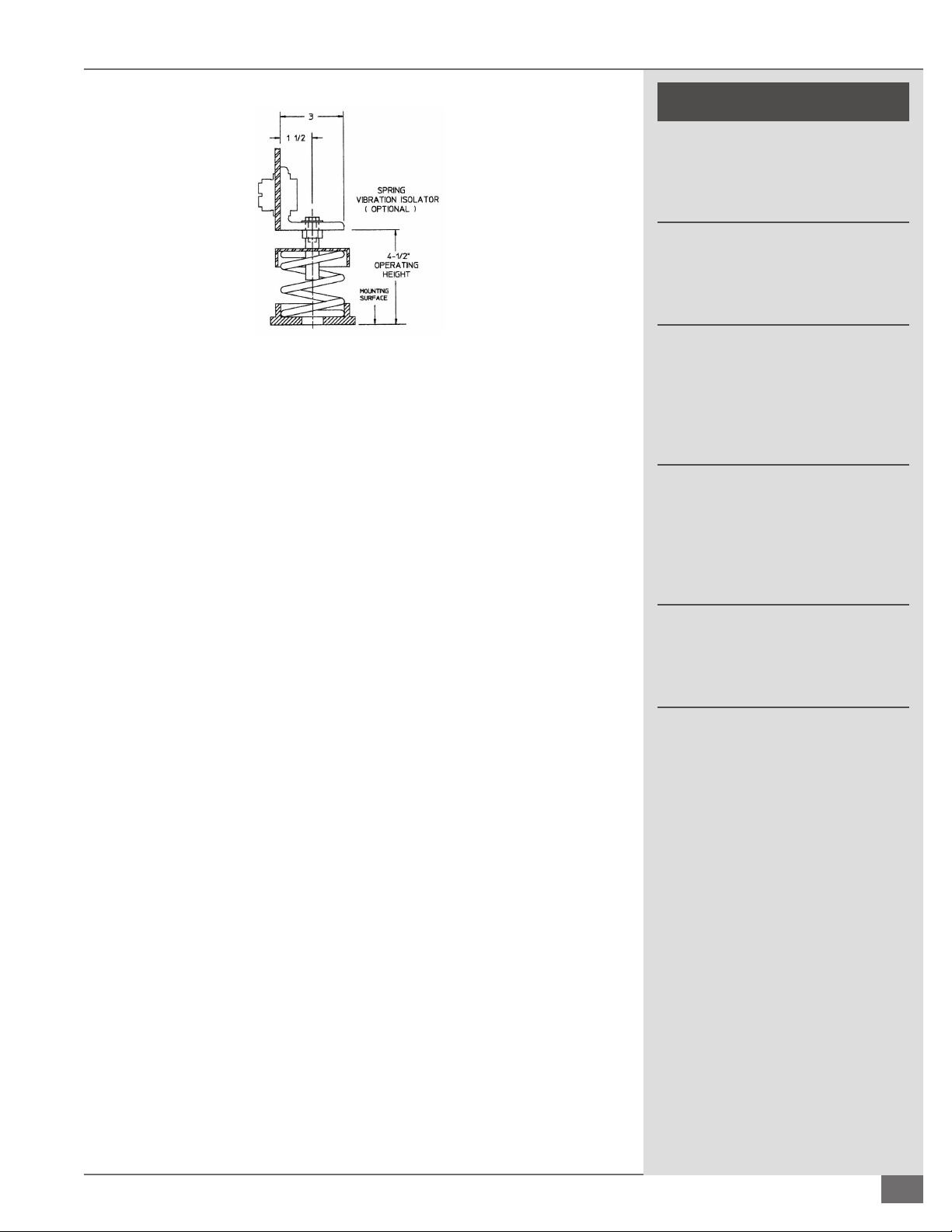
¡ How to Install Spring Isolation Mounts
Adhere to the following for Spring Isolation Mounts (see Figure 4):
1. Thread the leveling bolt into the top load plate of the spring until the head
of the bolt is within 1/8” of the top load plate of the spring.
2. Coordinate the location of each isolator.
3. Remove the small cap screw and washer. Raise the boiler with jacks or
similar tools. Do not attempt to raise the boiler via one lifting point, but lift
evenly around the perimeter of the boiler). Slide the spring isolator under
the boiler or mounting bracket with the bolt head on the underside of the
bracket.
4. Insert the small cap screw through the bracket and thread into the top of
the leveling bolt and tighten nger tight.
5. Lower the boiler (evenly) onto the spring isolators. Do not overload any
one isolator and take care not to push the boiler sideways.
6. Do not attempt to place all the weight on one spring, but distribute the
load proportionately by adjusting each isolator in sequence.
7. Continue to adjust each leveling bolt (in sequence) until the boiler is at
its proper height. When the boiler is lled with water, the springs will
compress approximately 1-2”.
2-6
8. Tighten the small cap screw, thus securing the spring isolator to the
supported equipment and locking the leveling bolt against turning.
© The Fulton Companies 2013
SECTION 2 PHW-IOM-2013-0214 INSTALLATION
! WARNING
The discharge from the safety relief
valve must be arranged to ensure
no danger of scalding personnel, or
equipment damage.
Provisions must be made to properly
pipe the safety relief discharge
away from the boiler to the point of
discharge.
FIGURE 4 - INSTALLING SPRING ISOLATION MOUNTS
NOTE: ´ Do not attempt to move the boiler laterally while it is supported
on the isolators. If it is necessary to move the boiler remove the weight
from the isolators by raising the boiler before moving. Failure to follow
this procedure could result in bent or broken leveling bolts or springs, or
damage to the neoprene bottom spring cap.
¡ How to Install Seismic Spring Isolation Mounts
Adhere to the following for installation of Seismic Spring Isolation Mounts (see
Figure 5):
1. Thread the leveling bolt 1/2” into the top of the load cap.
2. Remove the lock nut and one washer from the top of the leveling bolt.
Locate leveling nut as far down on leveling bolt as it will travel.
3. Coordinate the location of each isolator.
4. Place a one inch shim next to each bracket between the boiler and the
housekeeping pad or structural oor. If an operating clearance of other
than one inch is desired, use an appropriate size shim.
The hydronic system should never be
ushed while the boiler is attached
to the system since the debris could
accumulate in the boiler and block
water from passing through the heat
exchanger.
Ensure all labels on the boiler are
legible. All connections and safety
devices, both mechanical and
electrical, must be kept clean, with
ease of access for inspection, use and
maintenance.
Do not store or use gasoline or other
ammable vapors and liquids or
corrosive materials in the vicinity of
this or any other appliances.
5. Raise the boiler and slide the spring isolator under the equipment
mounting bracket with the leveling nut and one washer on the under side
of the bracket.
6. Lower the boiler onto the spring isolators taking care not to overload any
one isolator and taking care not to push the boiler sideways.
7. Install second washer and lock nut one inch down from top of leveling
bolt.
8. Turn the leveling nut in a counter-clockwise rotation until the boiler
just touches the shim. The shim may now be removed. Proceed with
adjustment of the other three isolators.
9. Tighten the lock nuts on the leveling bolts, thus bolting the spring to the
boiler and locking the leveling bolt against turning.
Questions? Call (315) 298-5121, or visit us online at www.fulton.com
2-7

INSTALLATION PHW-IOM-2013-0214 SECTION 2
! WARNING
Discharge from the safety relief valve
must be arranged so that there is no
danger of scalding. When the safety
relief valve is piped away from the
boiler to the point of discharge, there
must be provisions to properly drain
the piping.
No shuto of any kind may be placed
between the safety relief valve and
the boiler, or on the discharge pipe
between the safety relief valve and
the atmosphere. Doing so may
cause an accidental explosion from
overpressure.
4 CAUTION
NOTE: ´ Do not attempt to move the isolators laterally with the weight of the
boiler on them. If it is necessary to move the boiler, remove the weight from
the isolators by raising the equipment before moving.
FIGURE 5 - INSTALLING SEISMIC SPRING ISOLATION MOUNTS
Care needs to be taken to eliminate
oxygen from the water system, as
excess oxygen in the system will
reduce the life of any boiler. The
boiler warranty does not cover heat
exchanger replacement due to oxygen
contamination of boiler water.
Heat exchanger failure due to
inappropriate water quality, foreign
matter or debris damage is not covered
under the warranty.
If the piping system attached to this
unit will be chemically cleaned, the
boiler must be disconnected from the
system and a bypass installed so that
the chemical cleaning solution does
not circulate through the boiler.
Install Boiler Trim
Each boiler is supplied with a safety relief valve sized in accordance with ASME
requirements.
Adhere to the following for installation:
1. Connect the safety relief valve to the coupling located in the top of the
boiler. The safety relief valve must be installed with a 6” nipple (8” for
PHW2000) between the boiler and the safety valve. The safety relief valve
must always be installed in the vertical position. The discharge pipe shall
be not less than the full area of the valve outlet. The discharge pipe shall be
as short and straight as possible and so arranged as to avoid undue stress
on the valve.
2. Install pressure-temperature gauge in the side port of a tee installed in the
boiler water outlet. A tee is installed on the nipple.
Water Chemistry Requirements
All water supplies contain some amount of solids, dissolved gases and dissolved
minerals. These materials may promote corrosion, deposition and/or fouling
of equipment. To prevent these contaminants from impacting on boiler
performance, valve operation and general pipe longevity, each location must be
analyzed and treated accordingly. The following are installation recommendations
for “closed-loop” recirculating hot water heating systems.
2-8
1. Automatic pressure activated water make up valve with back ow preventer
providing water to the system, not fed directly to the boiler, set to maintain:
§ Required NPSH for recirculating pump(s).
© The Fulton Companies 2013
SECTION 2 PHW-IOM-2013-0214 INSTALLATION
ADDITONAL
BOILER (S)
HEATING
SUPPLY
MANIFOLD
ADDITIONAL
BOILER (S)
HOT WATER
STOP VALVE
TEMPERATURE
PRESSURE
GAUGE
OPERATING AND
HIGH LIMIT AQUASTATS
(INTERNAL)
ASME
SAFETY
VALVE
STOP
VALVE
DRAIN
CONDENSATE
DRAIN
Multiple Boiler Installation
TYPICAL PIPING SYSTEM
UNLESS OTHERWISE NOTED, ALL
COMPONENTS SHOWN ARE TYPICAL
ON EACH BOILER
HEATING
RETURN
MANIFOLD
EXPANSION
TANK
STOP
VALVE
CHECK
VALVE
PRESSURE
REDUCING
VALVE
MAKEUP
WATER
AUTOMATIC
AIR VENT
FLAME ROD
SPARK PLUG
§ A positive system pressure at the highest point of 5 to
10 psi.
§ Make up water valve should be designed to add water
to the system at the outlet of the boiler and should
not be fed directly into the boiler.
2. Air removal equipment, including air separator and
automatic air breather valves.
3. A functioning expansion tank designed to system
speci cations.
4. Filtration to remove particulates installed inline with the
suction side of the recirculating pump.
5. Bypass chemical feeder for corrosion inhibitor
maintenance.
6. Optionally a water meter could be installed in series
with the automatic pressure activated water make up
valve to monitor any make up water.
7. Ensure water quality meets the following:
§ Oxygen - less than 250 ppb (operating condition)
§ pH - must be in the range of 8-10
§ Total Iron & Copper - less than 25 ppm
§ Corrosion Inhibitor - level capable of maintaining
iron corrosion rates < 2 mpy. Due to changing
environmental restrictions, a non-heavy metal, all
organic inhibitor is recommended, which is designed
for multi-metal systems including ferrous metals and
yellow metals such as copper and brass.
§ Chlorides - less than 250 ppm as Cl. Limit applicable
only to installations utilizing duplex steel pressure
vessel components.
Install Water Piping
The bottom connection to the boiler is the INLET and must be
connected as the return from the system. The top connection
on the boiler is the OUTLET and must be connected as the
supply to the system.
FIGURE 6 - TYPICAL PIPING (MULTIPLE BOILER SYSTEM)
Questions? Call (315) 298-5121, or visit us online at www.fulton.com
2-9

INSTALLATION PHW-IOM-2013-0214 SECTION 2
! WARNING
All information in this manual is for
reference and guidance purposes,
and does not substitute for required
professional training, conduct, and strict
adherence to applicable jurisdictional/
professional codes and regulations.
Do not use matches, candles, ame or
other sources of ignition to check for gas
leaks.
If the water supply must be temporarily
disconnected from the condensate
trap, the boilers must be turned o to
prevent accidental ue gas emission
into the boiler room. An uninterruptible
water supply is required and shall be
connected to the ¼” compression tting
on the condensate drain. The water supply
maintains a water level in the drain kit to
prevent accidental ue gas emission into
the boiler room.
Adhere to the following for water piping installation (Figure 6):
1. Connect hot water supply to heating system feed line.
2. Connect expansion tank.
3. Connect return water to boiler return water connection.
4. Install an air separator and air eliminator (air vent) which is necessary as
there is no built in boiler air eliminating feature.
5. If a sealed diaphragm-type expansion tank is used, install air eliminator in
hot water piping at air separator.
6. If an air cushion type expansion tank is used, pipe tank directly into boiler
supply.
7. On multi zoned systems (or a system with both space and domestic water
heating), air elimination must be provided either in the common piping or
every loop. When the boiler is installed at a higher level than baseboard
radiation, air elimination must be provided directly above the unit.
8. Install hot water circulator, remote mounted from boiler. Do not attach
directly to the boiler. Flexible connectors must be placed between the
circulator and the boiler.
Cements for plastic pipe are ammable
liquids and should be kept away from all
sources of ignition. Proper ventilation
should be maintained to reduce the
hazard and to minimize breathing of
cement vapors. Avoid contact of cement
with skin and eyes.
4 CAUTION
Some soap used for leak testing is corrosive
to certain types of metals. Clean all piping
thoroughly after completing the leak check.
NOTE: ´ For all models, a no ow condition will not damage the heat
exchanger, however, adequate ow should be provided to prevent tripping
the boiler on high temperature limit.
9. For boilers with carbon steel or duplex steel heat exchangers, the
maximum allowable temperature di erential across the heat exchanger
is 100 degrees F. Minimum outlet temperature for carbon steel units must
be 120 degrees F or greater. Maximum allowable working temperature for
carbon steel units is 240 F. High limit is set at 230 F, therefore operating at
a temperature greater than 220 F is not recommended. For duplex steel
units, maximum allowable working temperature is 210 F. High limit is set
at 200 F, therefore operating at a temperature greater than 190 F is not
recommended.
10. Install manual purging valves in all loops and zones. Install pressure
reducing (automatic ll) valve in the cold water ll line to the boiler system.
11. Check that the proposed operation of zone valves, zone circulator(s) and
diverting valves will not isolate air separator(s) and/ or expansion tank(s)
from the boiler.
12. Clearance from hot water pipes to combustibles must be at least 6”.
13. The boiler, when used in conjunction with a refrigeration system, must
be installed so the chilled medium is piped in parallel with the boiler
with appropriate valves to prevent the chilled medium from entering the
boiler. If the boilers are connected to heating coils, located in air handling
units where they may be exposed to refrigerated air circulation, such
boiler piping systems shall be equipped with ow control valves or other
automatic means to prevent gravity circulation of the boiler water during
2-10
© The Fulton Companies 2013

SECTION 2 PHW-IOM-2013-0214 INSTALLATION
the cooling cycle.
14. The boiler is furnished with a probe type low water
cuto . No eld piping is required. If the probe does
not sense water, the boiler will shut down and a red
indicator will be illuminated on the control panel.
15. The boiler is not provided with external drain
connections. A drain valve must be installed near the
inlet connection to the boiler and piped to a suitable
oor drain. A Boiler Drain Assembly can also be
purchased from Fulton. This Boiler Drain Assembly must
be installed near the inlet connection to the boiler.
16. Before lling the boiler clean and ush the system
to remove any debris. Clean and ush old piping
thoroughly before installing the boiler. Consider
installing a strainer ahead of the boiler.
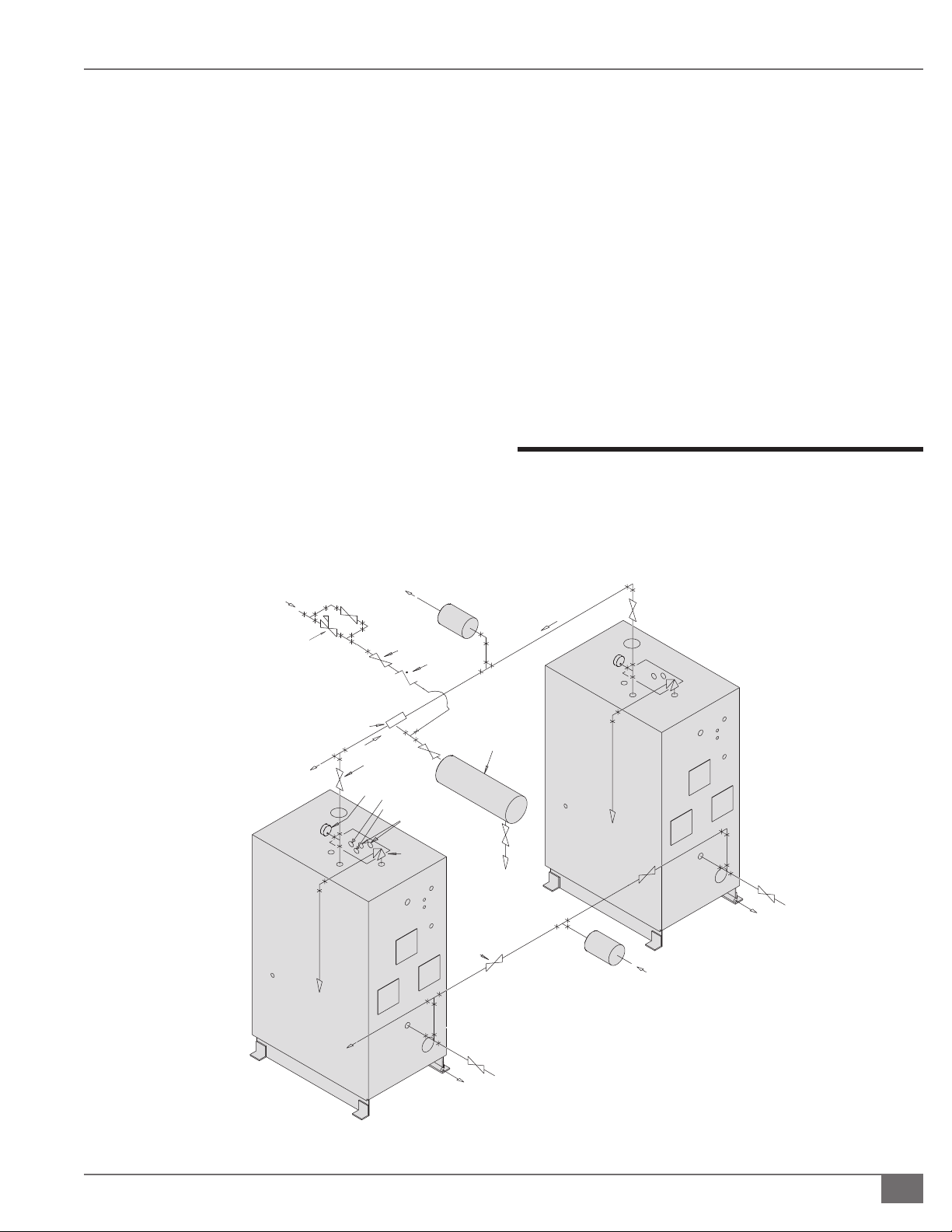
Install Condensate Drain
The condensate drain kit is intended for use with any size
Pulse unit supplied by Fulton. The 3/4” condensate drain on
the pulse unit will be connected to the 1” inlet on the drain
kit. One or more drain lines may be connected to this inlet
(maximum of 12 MM BTU/hr) through a common header. See
Figure 7.
Adhere to the following for installation:
1. An uninterruptable water supply is required and shall
be connected to the 1/4” compression tting on the
drain oat. The water supply maintains a water level in
the drain kit to prevent the ue gas from entering the
boiler room through the condensate connection. The 1
1/2” connection shall be piped to an appropriate drain
for disposal. If the water supply must be temporarily
disconnected, the boiler(s) must be turned o to
prevent accidental ue gas emission into the boiler
room.
2. Keep the cover on at all times, except during
maintenance of the drain. This drain should be
monitored and checked regularly in your Pulse
maintenance schedule.
3. A condensate collecting tank and condensate pump
FIGURE 7 - MULTIPLE BOILER CONDENSATE DRAIN INSTALLATION
Questions? Call (315) 298-5121, or visit us online at www.fulton.com
2-11

INSTALLATION PHW-IOM-2013-0214 SECTION 2
! WARNING
All information in this manual is for
reference and guidance purposes,
and does not substitute for required
professional training, conduct,
and strict adherence to applicable
jurisdictional/professional codes and
regulations.
DO NOT USE GASOLINE, CRANKCASE
OIL OR ANY OIL CONTAINING
GASOLINE. If in doubt, contact
your Fulton representative prior to
operation.
Do not store or use gasoline or other
ammable vapors and liquids or
corrosive materials in the vicinity of
this or any other appliances. Cements
for plastic pipe should be kept away
from all sources of ignition. Proper
ventilation should be maintained to
reduce the hazard and to minimize
breathing of cement vapors.
will be required if a oor drain is not available to discharge to (Collecting
tank and pump are not supplied with the boiler). Complete condensate
drain kits are available from Fulton.
¡ Install Condensate Drain Piping
Adhere to the following when installing condensate drain piping:
1. All piping must be galvanized or stainless steel and should be free of leaks.
2. Make sure either elastomer coated berglass cubes or spring mounts have
been installed under each leg of the boiler.
3. Install the condensate piping to the condensate drain in the lower right
hand side of the boiler.
4. Connect 3/4” condensate drain(s) to the 1” header connected in a manifold.
The header must be at least 5 ½” below the condensate outlet of the
individual boiler and must remain ooded by being at least 5 ½” below the
outlet of the condensate drain trap..
5. Connect 1½” drain outlet to an appropriate waste line following applicable
codes. The 1½” drain connection on the condensate drain must be the
highest point prior to going to the drain. Failure to keep drain piping lower
than this point will result in over ow of the condensate drain. Slope the
drain pipe away at a minimum pitch of 1” for every 12 feet.
Do not attempt to start boiler to test
wiring before lling and purging the
boiler. A dry re will seriously damage
the boiler and may result in property
damage or personnel injury and is
not covered by warranty.
4 CAUTION
The vent line connection on the gas
pressure regulator must be piped in
accordance with National Fuel Gas
code, latest addenda. In Canada, gas
installations must be in accordance
with current CAN/CGA, and/or local
codes.
6. Attach a 1/4” water supply to the compression tting on the oat. The
water line must be connected to an uninterruptible supply. Fulton
recommends connecting it before the “Fast-Fill” valve to the boiler supply
but after the back ow preventer to avoid contamination of a potable
water supply. Maximum allowable water pressure to the compression
tting is 100 PSI.
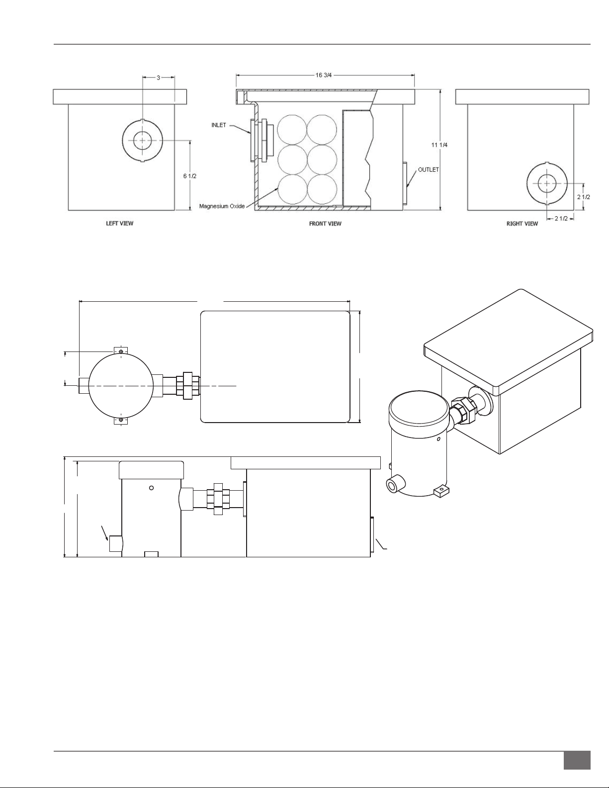
Install pH Neutralization Kit
The pH Neutralization Kit is a Fulton-provided kit designed to bring the pH level
of the boiler’s condensate to a neutral level. It is not a replacement or alternative
for the Condensate Drain Trap. See Figure 8.
Adhere to the following for installation:
1. Use stainless or galvanized pipe and ttings to connect condensate drain
to kit.
2. Connect kit downstream of Condensate Drain Trap. See Figure 9.
3. Pipe outlet to appropriate drain.
NOTE: ´ Replacement bags are available from the Fulton Parts Department.
The medium in the container will neutralize the condensate of 12 MM Btu’s
for approximately 6 months.
2-12
© The Fulton Companies 2013
SECTION 2 PHW-IOM-2013-0214 INSTALLATION
TOP VIEW
30 3/8
[771]
12 1/2
[318]
3 13/16
[97]
(TYP.)
FRONT VIEW
1 1/2" PLASTIC FITTING
CONNECTION TO DRAIN
1" NPT
CONNECTION
TO BOILER
10 3/4
[273]
11 1/4
[286]
ISOMETRIC VIEW
FIGURE 8 - FULTON PH NEUTRALIZING KIT (WITHOUT PUMP)
FIGURE 9 - FIELD CONNECTIONS FOR CONDENSATE DRAIN TO PH NEUTRALIZATION TANK
Questions? Call (315) 298-5121, or visit us online at www.fulton.com
2-13
INSTALLATION PHW-IOM-2013-0214 SECTION 2
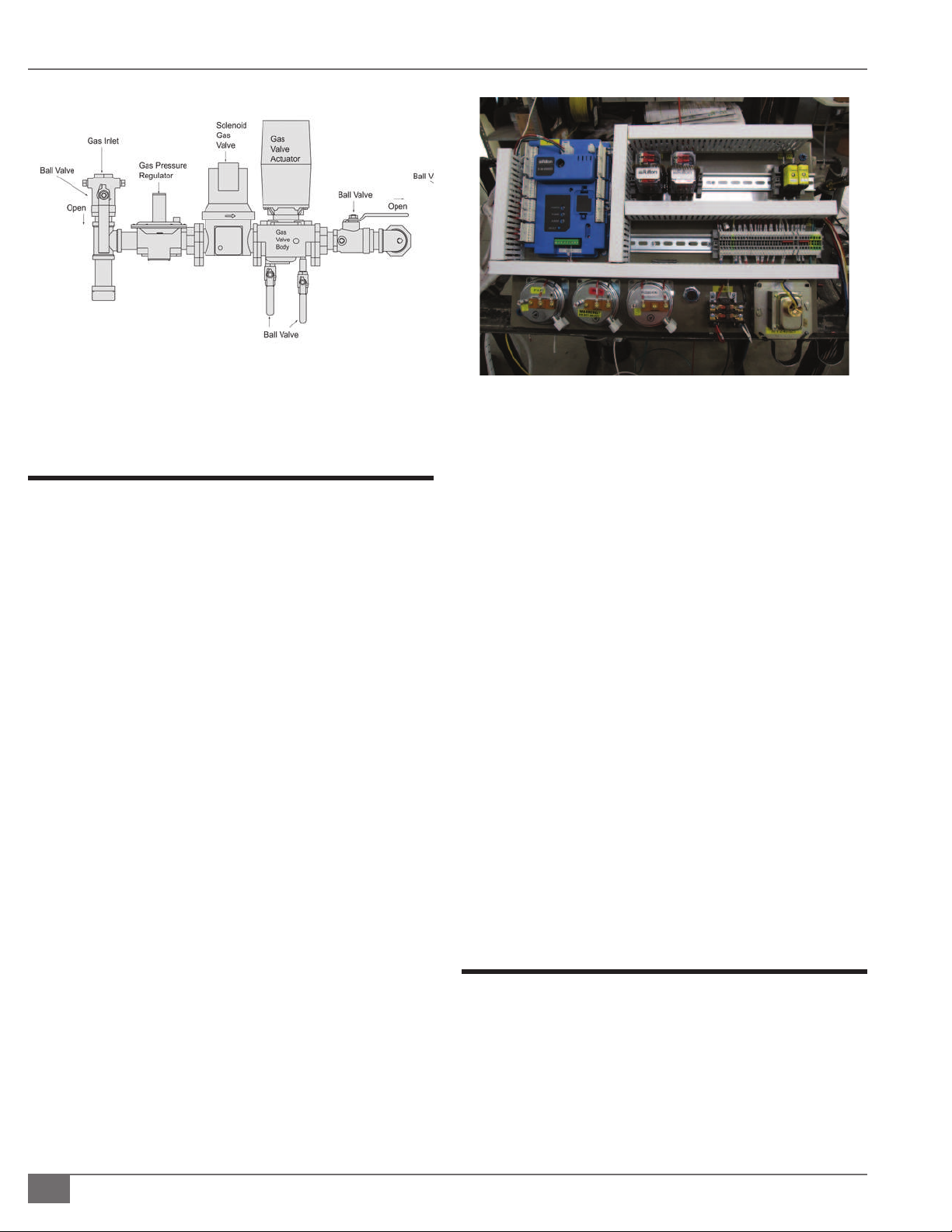
FIGURE 10 - GAS VALVE CONFIGURATION
Install Gas Piping
Adhere to the following for gas piping installation:
1. Gas Piping should be installed in accordance with
National Fuel Gas Code, ANSI Z223 1 1991 or latest
addenda and any other local codes which may apply.
In Canada gas installations must be in accordance with
the current CAN/CGA B149.1 and .2 and/or local codes.
2. The pipe and the ttings used should be new and free
of dirt or other deposits. Piping must be of the proper
size to insure adequate gas supply.
NOTE: ´ Do not use the boiler’s gas train inlet size as a
gauge for inlet piping size. Always refer to appropriate
gas piping charts.
NOTE: ´ Full port ball valves approved for gas should be
used for gas isolation to reduce pressure drop.
3. Gas pressure to inlet of gas train should be 7” WC for
natural gas and 11” WC for propane (PHW2000LE
requires 11”WC on natural gas). Connect gas supply
line to the open end of the tee on which the drip leg is
installed. See Figure 10.
FIGURE 11 - FIELD WIRING
6. The boiler must be isolated from the gas supply piping
system by closing its individual manual shut o valve
during any pressure testing of the gas supply system at
more than 1/2psi (3.5kPa).
7. Gas vents to outdoor air must be provided for the gas
pressure regulator. Restricting ori ces or bleed ori ces
should not be used at anytime. The vent line connection
on the gas pressure regulator must be piped to outdoor
air by installer in accordance with the National Fuel Gas
Code, ANSI Z223- 1-1991 or latest addenda.
8. In Canada gas installations must be in accordance with
the current CAN/CGA B149.1 and .2 and/or local codes.
} HONEYWELL PRESSURE SWITCH
The Honeywell C6097 pressure switch is designed with
internal vent limiters to meet UL 353 requirements and are
CSA certi ed, UL listed, FM approved, and CSD-1 acceptable.
Local codes may not permit a gas device (pressure switch)
without an external vent line connection. If that is the case, a
vent line must be added.
Install Field Wiring
4. When making gas piping joints, use a sealing
compound resistant to the action of lique ed
petroleum gases. Do not use Te on tape on gas line
threads.
5. After gas piping is completed and before wiring
installation is started, carefully check all piping
connections, (factory and eld), for gas leaks. Use a soap
and water solution.
2-14
Adhere to the following for eld wiring installation (see
Figures 11 and 52):
1. An independent power supply line is recommended
for the boiler. Connect one 120 volt (60Hz) fused power
line to terminal block to hot, or marked terminal per
electrical diagram. Connect applicable wires to neutral
and ground. Connect a ground wire to green colored
ground lug in electrical control box.
© The Fulton Companies 2013

SECTION 2 PHW-IOM-2013-0214 INSTALLATION
2. Ensure gas ignition system components are protected from water
(dripping, spraying, rain, etc.) during boiler operation and service.
3. Any attempt to start the boiler to test wiring prior to lling and purging
may result in a dry re and void the warranty.
Air Intake Supply Piping Installation Preparation
The boiler is equipped with air intake supply and exhaust vent connections
located at the top and rear of the boiler respectively. See Figure 12. Air supply
is on the top. For Models PHW300 and PHW500 these connections are 3” NPT
threaded female ttings and for Models PHW750, PHW950, PHW1000, and
PHW1400 they are 4” NPT thread female ttings. These ttings will accept 3” and
4” male/female pipe to tubing adaptors respectively. Model PHW2000 has 6”
NPT threaded female tting. In supporting piping, or routing it through a rafter
or wall, always use vibration eliminating hangers around the piping to prevent
vibration transmission. Always avoid rigid connections between piping and
structural members of the building.
1. For sealed combustion applications, air intake must be piped out of the
building. Air Intake pipes and ttings for all models shall be Schedule 40
PVC pipe. All Schedule 40 PVC pipe, ttings, primer and cement must
conform with American National Standard Institute and the American
Society for Testing and Materials (ANSI/ASTM standards).
! WARNING
All information in this manual is for
reference and guidance purposes,
and does not substitute for required
professional training, conduct,
and strict adherence to applicable
jurisdictional/professional codes and
regulations.
Do not attempt to start boiler to test
wiring before lling and purging the
boiler. A dry re may cause injury,
boiler damage, and/or property
damage, and is not covered by
warranty.
Do not use the boiler/burner as
support for ducted air piping.
Ducted piping must be supported
independently of the boiler.
Do not terminate venting into an
enclosed area.
2. For applications using make up air from the boiler room, a minimum of 10’
of venting including the intake mu er must be installed. Per ASME Section
VI Para. 6.04, an unobstructed air ventilation opening should be sized on
the basis of one square inch free area per 2000 BTU/HR maximum fuel
input of the combined burners located in the boiler room. This is subject to
state and local regulations. The installation of exhaust fans in a boiler room
is not recommended.
Never use open ame or smoke from
a cigarette, cigar, or pipe as a testing
method during boiler installation,
operation, or maintenance.
Foreign substances, such as
combustible volatiles in the
combustion system can create
hazardous conditions. If foreign
substances can enter the air stream,
the boiler combustion air inlet must
be piped to an outside location.
Particulate matter or chemicals in the
combustion air supply to the boiler
will cause damage to air apper
gaskets, could cause the unit to fail
to light, and is not covered under
warranty.
FIGURE 12 - AIR INLET LOCATION
Questions? Call (315) 298-5121, or visit us online at www.fulton.com
2-15
INSTALLATION PHW-IOM-2013-0214 SECTION 2
4 CAUTION
Intake PVC piping must be assembled using
cement. This ensures that the intake is air
tight and will not allow contaminants
to enter the boiler from the boiler room.
Cement must be free- owing and contain
no lumps, undissolved particles or any
foreign matter that adversely a ects the
joint strength or chemical resistance of the
cement. The cement must show no gelation,
strati cation, or separation that cannot be
removed by stirring.
Cements for plastic pipe are ammable
and should be kept away from all sources
of ignition. Proper ventilation must be
maintained to prevent cement vapor
hazards. Avoid contact with skin and eyes.
3. All alternative individual venting arrangements must result in an intake
pressure drop not to exceed 2.5” w.c. (Consult factory for assistance.)
4. All common venting arrangements must result in a pressure drop of less
than 0.1” w.c. in the common header. (Consult factory for assistance.)
NOTE: ´ Intake PVC piping must be assembled using cement. This will ensure
that the intake is air tight and will not allow contaminates from the boiler
room into the boiler. The cement shall be free owing and contain no lumps,
undissolved particles or any foreign matter that adversely a ects the joint
strength or chemical resistance of the cement. The cement shall not show
gelation, strati cation, or separation that cannot be removed by stirring.
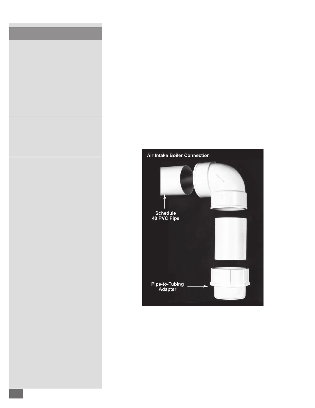
¡ Cementing Joints
Adhere to the following procedure (per ASTM D2855) (see Figure 13):
2-16
FIGURE 13 - AIR INTAKE BOILER CONNECTION
1. Measure and cut PVC pipe to desired length.
2. Chamfer end of pipe, removing any ridges or rough edges. If end is not
chamfered, the edge of the pipe may remove cement from the tting
socket and result in a leaking joint.
3. Clean and dry surfaces to be joined.
4. Test t joint and mark depth of tting on the pipe.
© The Fulton Companies 2013

SECTION 2 PHW-IOM-2013-0214 INSTALLATION
5. Uniformly apply liberal coat of primer to inside socket surface of tting and
male end of pipe to depth of tting socket.
6. Promptly apply solvent cement to end of pipe and inside socket surface
of tting. Cement should be applied lightly—but uniformly—to inside of
socket. Take care to keep excess cement out of socket. Apply second coat
to pipe end. Time is critical at this stage. Do not allow primer to dry before
applying cement.
7. Immediately after applying last coat of cement to pipe, while inside socket
surface and end of pipe are wet with cement, insert end of pipe into
socket, turn pipe 1/4 turn to distribute cement evenly, continue to insert
pipe until it bottoms out.
NOTE: ´ Assembly should be completed within 20 seconds after last
application of cement. Do not use hammer to insert pipe.
8. After assembly, wipe excess cement from pipe at end of tting socket. A
properly made joint will show a bead around its entire perimeter. Any gaps may
indicate a defective assembly due to insu cient cement.
9. Handle joints carefully until completely set.
! WARNING
All information in this manual is for
reference and guidance purposes,
and does not substitute for required
professional training, conduct, and strict
adherence to applicable jurisdictional/
professional codes and regulations.
Install Intake Muffl er
To install intake mu er, cement joints as indicated in previous section. For
best noise attenuation, the mu er should be installed as close to the boiler
as possible, and can be horizontal or vertical in orientation.
Preparing to Install Exhaust Vent Piping
A Fulton Pulse boiler should not be connected to a common venting system with
other types of gas appliances. Adhere to the following when preparing to install
vent piping:
1. The boiler is equipped with an exhaust vent connection located at the
rear of the boiler. For models PHW300 up through the PHW1400, the
connection is 4” NPT threaded female. Model PHW2000, the connection is
6” NPT threaded female.
2. The exhaust line must be sloped down toward the boiler with a pitch of
at least 1/4” per foot. Failure to do so can result in a condensate pocket
which can result in an inoperative boiler. There must be no low spots in
the exhaust pipe, as this can also result in a condensate pocket. A high spot
is acceptable, provided the pitch from the high spot is maintained back to
the boiler or to the outside point of the exhaust. In supporting piping, or
routing it through a rafter or wall, always use vibration eliminating hangers
around the piping to prevent vibration transmission. Always avoid rigid
connections between piping and structural members of the building.
3. All alternative individual venting arrangements must result in an exhaust
pressure drop not to exceed 2.5” w.c. (Consult factory for assistance.)
Questions? Call (315) 298-5121, or visit us online at www.fulton.com
2-17

INSTALLATION PHW-IOM-2013-0214 SECTION 2
! WARNING
Crystalline silica may be present in
components of this equipment. Exposure
to crystalline silica may pose signi cant
health hazards, including but not limited to
eye and respiratory system damage. Per the
Centers for Disease Control and Prevention
(CDC) and Occupational Safety and Health
Administration (OSHA), appropriate
Personal Protective Equipment must be
worn to minimize exposure to hazardous
substances. Refer to most current guidelines
o ered by the CDC and OSHA for more
information, including Personal Protective
Equipment recommendations.
4 CAUTION
To prevent potential water damage, never
leave an open manual air vent unattended.
4. All common venting arrangements must result in a pressure drop of -0.1”
to 0.0” w.c if not using a draft assist fan. (Consult factory for assistance.)
5. All common venting arrangements must result in a pressure drop of
0.0” to 0.75” w.c. with the use of a draft assist fan. (Consult factory for
assistance.)
6. Variable speed exhaust fan pressure setting should be no more than 0.1”
w.c.
7. Flue vent pipes and ttings for all Pulse boilers must be UL listed for use
with Category IV, positive pressure, condensing equipment. Speci cally
this material is AL294C. Stainless Steel 316L piping is also acceptable.
At 480°F temperature rating, a 5” minimum air space clearance to
combustibles is required. Applicable Federal Codes are NFPA 54/ANSI
Z223.1 National Gas Code and NFPA/ANSI 211 Chimneys, Fireplaces, Vents
and Solid Fuel Burning Appliances. In Canada, refer to the venting section
of CAN/CGA B149.1 and 2. The gas vent installer should be familiar with
these federal codes as well as any local codes and regulations that may
apply. The procedure for adhesive joining stainless steel pipe and ttings
follows:
§ Do not mix stainless steel pipe with galvanized or other alternatives
for the entire length of the system.
§ All joints between sections of the vent connector and the vertical
conduit must be sealed with a high temperature sealant or gasket to
prevent any possible leakage of ue gas.
§ Apply a bead of sealant, about 1/2“ in diameter, completely around
the male (without tabs) end of each conduit section or elbow,
between 1/4” and 3/8” from the end of the section. Also run a similar
sized bead down the seam weld of each section, from the edge of
the pipe to the top of the bulge.
§ Fully insert the male end of the section into the female tting of
the section below. Attach the sections together. Inspect the joint to
ensure that ue gases will not escape. If necessary, apply additional
sealant to any voids. Allow the sealant 24 hours to cure before
operating the boiler.
§ See speci c manufacturers instructions for complete installation
details.
Exhaust Muffl er Installation
Adhere to the following for mu er drain installation:
2-18
§ For mu ers installed in the vertical con guration the drain can be
plugged.
§ For mu ers installed in the horizontal con guration, the drain opening
should be at the down slope (6 o’clock) position, and should be piped
to the drain line between the boiler and the condensate drain. For best
sound attenuation, the mu er should be installed as close to the boiler as
possible.
© The Fulton Companies 2013

SECTION 2 PHW-IOM-2013-0214 INSTALLATION
Air Intake & Exhaust Piping Requirements for the
Pulse Boiler
Adhere to the following for air intake and exhaust piping:
1. Use piping that matches the inlet/outlet connection sizes for the rst 35
feet and 4 elbows closest to the boiler. See Tables 2 and 3.
§ The piping can be extended to 100 feet and 6 elbows by increasing the
pipe size to 6” for the PHW300 - PHW1000, and to 8” for the PHW2000.
§ For the PHW1400, the air intake and exhaust piping must be 4” for the rst
10 feet and then piping must be upsized to 6” for up to 40 feet. If going
beyond 40 feet, instead of upsizing to 6” after the rst 10 feet, upsize to
8”.
§ It is acceptable to extend the piping up to 100 feet and 6 elbows with
proper sizing.
2. A minimum of 10 feet of piping is required on the air intake (even if
taking combustion air from the boiler room) or exhaust. This creates the
appropriate amount of backpressure for pulse combustion to operate
properly.
! WARNING
All information in this manual is for
reference and guidance purposes,
and does not substitute for required
professional training, conduct, and strict
adherence to applicable jurisdictional/
professional codes and regulations.
3. If air intake or exhaust layouts require upsizing, keep the rst 10 feel closest
to the boiler matching the outlet connection size of the boiler.
4. If utilizing a common header pipe for multiple pulse boilers, the pressure
drop across a common intake pipe must be neutral. The pressure drop
across a common vent pipe must be between -0.1 and 0” W.C. if not
utilizing a mechanical draft system.
5. Exhaust runs should, individually, not have pressure drops of more than
3.0” WC. Intake is +2.0”WC.
TABLE 2 - AIR INTAKE PIPING REQUIREMENTS
Model PHW Type Base
Diameter
(inches)
300 PVC 3
3
500 PVC 3
3
750 PVC 4
4
1000 PVC 4
4
1400* PVC 4
6
2000 PVC 6
6
Length (feet) Number of
90-degree
Elbows
10 minimum
35 maximum
10 minimum
35 maximum
10 minimum
35 maximum
10 minimum
35 maximum
10 minimum
35 maximum
10 minimum
35 maximum
0
4
0
4
0
4
0
4
0
4
0
4
Questions? Call (315) 298-5121, or visit us online at www.fulton.com
2-19

INSTALLATION PHW-IOM-2013-0214 SECTION 2
! WARNING
Do not attempt to start boiler before
lling and purging boiler heating system.
A dry re will seriously damage the boiler
and may result in property damage or
personnel injury and is not covered by
warranty.
Operating the boiler beyond its design
limits is dangerous and may also cause
boiler damage. Do not attempt to upgrade
boiler performance with unapproved
modi cations.
TABLE 3 - EXHAUST VENT PIPING REQUIREMENTS
Model PHW Type Base
Diameter
(inches)
300 Stainless Steel
AL294C
500 Stainless Steel
AL294C
750 Stainless Steel
AL294C
1000 Stainless Steel
AL294C
1400* Stainless Steel
AL294C
2000 Stainless Steel
AL294C
*A minimum 10 feet of 4 inch air intake and exhaust is required for the PHW-1400. Air
intake and exhaust con gurations over 10 feet in length will require 4 inches for the rst
10 feet from the boiler, and then 6 inches up to an additional 40 feet, and four elbows.
4
4
4
4
4
4
4
4
4
6
6
6
Length (feet) Number of
90-degree
Elbows
10 minimum
35 maximum
10 minimum
35 maximum
10 minimum
35 maximum
10 minimum
35 maximum
10 minimum
35 maximum
10 minimum
35 maximum
0
4
0
4
0
4
0
4
0
4
0
4
Air Intake Supply and Exhaust Vent Installation
Adhere to the following for air intake supply and exhaust vent installation:
1. Air intake supply and exhaust vent pipes and ttings are suitable for
vertical, through-the-roof or horizontal through-the-wall installation.
The vent system must be installed in accordance with the manufacturer’s
instructions.
2. All vent pipes and ttings must be installed with appropriate air space
clearances to combustibles. These air space clearances apply to indoor or
outdoor vents—whether they are open, enclosed, horizontal or vertical or
pass through oors, walls, roofs, or framed spaces. See Figure 14. The air
space clearances should be observed to joists, studs, sub oors, plywood,
drywall or plaster enclosures, insulating sheathing, rafters, roo ng, and any
other material classed as combustible.
3. The required minimum air space clearances also apply to electrical wires
and any kind of building insulation away from gas vent and out of the
required air space clearance.
4. Vertical runs or vent pipes and ttings passing through oors, ceilings, or
in framed walls must be re stopped at oors and ceilings. The re stop
must close in the area between the outside of the vent and the opening in
the structure. (Figure 15). When passing through a oor or ceiling frame,
provide an opening 5” to 9” air space clearance to vent pipe as applicable.
The re stop ts to the bottom of a framed opening 13 1/4” square. Nail
into the inside of the framed opening through the four holes in the ring.
The re stop is placed on top of a framed opening 14 1/4” square with the
dished position down. Nail the ange to the top of the framing.
2-20
© The Fulton Companies 2013

SECTION 2 PHW-IOM-2013-0214 INSTALLATION
5. Pass the vent pipe through the opening in the re stop. If used as a
support, install the support ring around the vent pipe above the re
stop. Slide the support ring down to the top of the re stop and tighten
it securely to the vent pipe. Firestop supports can support up to 10 feet
of vent pipes and are recommended at all oor and ceiling penetrations.
Figure 16. Air intake supply and exhaust vent pipes and ttings must be
securely supported.
6. Horizontal sections require supports every 5 feet and at elbows. From
the boiler, all horizontal sections must rise at leas 1/4” per foot, and there
must be no sags or dips where condensate could collect. The upward pitch
is required so condensate will run back to the boiler for collection and
disposal.
7. For vertical through the roof installations all gas vents extending above the
roof by more than 2 1/2 feet must be securely guyed or braced (inside and
outside wall) 2 clamps. Use a support ring to attach guys or braces to the
vent pipe.
NOTE: ´ All venting must be mounted using spring isolators.
Vertical Vent Flashing and Installation
! WARNING
All information in this manual is for
reference and guidance purposes,
and does not substitute for required
professional training, conduct, and strict
adherence to applicable jurisdictional/
professional codes and regulations.
Adhere to the following for vent ashing installation:
1. The roof opening should be located and sized such that the vent is vertical
and has the required air space clearance. The roof ashing is positioned
with the lower portion of the base ange over roo ng material. See Figure
17.
2. Nail through the upper portion and sides of the base ange. Use nail with
neoprene washers or cover the nail heads with a neoprene plastic. Finish
roo ng around the ashing, covering the sides and upper ange with
roo ng material.
Vertical Vent Termination
Adhere to the following for vertical vent termination:
1. The vent pipe must extend through the ashing to a height above the roof
as required in Figure 18. A storm collar is installed on the vent pipe over the
opening between pipe and ashing.
2. Adhesive material is used over the joint between the vent pipe and the
storm collar. Figure 18. The vent termination is joined to the end of the vent
pipe.
3. Termination height for the vent pipe must be such that no discharge
opening is less than 2 feet horizontally from the roof surface, and the
lowest discharge opening shall be no lower than the minimum height
speci ed in Fig. 18. These minimum heights may be used provided the
vent is not less than 8 feet from any vertical wall.
Questions? Call (315) 298-5121, or visit us online at www.fulton.com
2-21

INSTALLATION PHW-IOM-2013-0214 SECTION 2
90° ELBOW
WIRES AND INSULATION
TO COMBUSTABLES,
AIR SPACE CLEARANCES
MAINTAIN MIN 9" / 22.86 CM
EXHAUST PIPE
& FITTINGS
AL294C
AIR INLET
RISE TO RUN: 1/4" PER FOOT
Pulse
Boiler
( SIDE VIEW )
1/4" TAPPING FOR WATER\
100 PSI MAXIMUM
INSTALL SUPPORT STRAPS AND SPRING HANGERS
AT 5FT / 152CM HORIZONTAL
INTERVALS AND AT ELBOWS
( SPRING HANGERS ARE REQUIRED )
SUPPORT
ROOF
RECIRCULATION DURING DIFFERENT
POSSIBLE TO PREVENT FLUE GAS
SHOULD BE SEPERATED AS FAR AS
AIR INTAKE AND EXHAUST TERMINATION
NOTE:
( } 3 IN. / 7.62 CM )
4FT / 122 CM
FLASHING
ADJUSTABLE
SPACE CLEARANCE
IN REQUIRED AIR
INSULATION
DO NOT PLACE
PVC PIPE
FIRE STOP
METAL PLATE
PIPING
ABOVE AIR INTAKE
MIN 4FT / 122 CM
ADJUSTABLE
FLASHING
ADHESIVE SEAL
STORM COLLAR
OF AIR INTAKE OPENING
EXHAUST STACK IS DOWNWIND
SCREENED INLET
IF SNOW ACCUMULATION IS
APPLICABLE, OPENING TO BE
1 FT. / 30 CM ( MIN. ) ABOVE THIS
NORMALLY EXPECTED LEVEL.
( SUGGESTED TERMINATION CONFIGURATIONS )
TYPICAL ROOF PENETRATIONS
WIND CONDITIONS.
NOTE: STACK SHOWN IS FOR REFERENCE PURPOSES ONLY. OTHER CONFIGURATIONS MAY BE ACCEPTABLE.
EXHAUST
USE OF ISOLATION CUBES OR SPRINGS IS REQUIRED
EXAMPLE OF SPRING HANGER
PROPER TRAP HEIGHT MUST BE ACHEIVED, AS SHOWN IN FIGURE 7
2-22
FIGURE 14 - TYPICAL CEILING AND ROOF PENETRATION DETAIL
© The Fulton Companies 2013

SECTION 2 PHW-IOM-2013-0214 INSTALLATION
FIGURE 15 - FIRE STOPPING REQUIRED FOR ALL CEILING/FLOOR
INSTALLATIONS
FIGURE 16 - FIRE STOPPING
FIGURE 17 - CORRECT ROOF FLASHING INSTALLATION
Questions? Call (315) 298-5121, or visit us online at www.fulton.com
2-23

INSTALLATION PHW-IOM-2013-0214 SECTION 2
FIGURE 18 - ROOF PITCH
Horizontal Installation Wall Penetrations
Adhere to the following for horizontal wall penetrations:
1. Select the point of penetration where a minimum of
1/4” per foot upward pitch can be maintained.
2. When penetrating a non-combustible wall, the hole
through the wall must be large enough to maintain
the pitch of the vent and provide sealing. Use adhesive
material to seal around the vent on both sides of the
wall. When penetrating a combustible wall, a wall
thimble must be used. See Figure 19 for installation
instructions. Minimum wall thickness through which
vent system may be installed is 3 1/4”. Maximum wall
thickness through which vent system may be installed
is 20 inches.
Wall Thimble Installation
Adhere to the following for wall thimble installation:
1. Insert a 9” diameter thimble through the wall from the
outside. Secure the outside ange to the wall with nails
or screws, and seal with adhesive material.
2. Install the inside ange to the inside wall, secure with
nails or screws, and seal with adhesive material.
3. Pass the vent pipe through the thimble from the
outside and join to the rest of the vent system. Seal the
pipe to the thimble ange with adhesive material. See
Figure 20.
4. Install two pipe retaining clamps around the intake
as well as vent pipes on both ends of the wall thimble
(on the inside and outside of the wall) through which
2-24
© The Fulton Companies 2013

SECTION 2 PHW-IOM-2013-0214 INSTALLATION
FIGURE 19 - HORIZONTAL INSTALLATION WALL PENETRATIONS
intake and vent pipes are passed, then tighten securely.
They will prevent the intake and vent pipes from being
pushed or pulled.
Horizontal Vent Termination
Adhere to the following for horizontal vent terminations:
1. Join the vent termination to the vent pipe outside the
Questions? Call (315) 298-5121, or visit us online at www.fulton.com
wall. Use the same joining procedures for vent pipe and
ttings.
2. Ensure the termination of the vent system is at least 12”
above the nished grade, or at least 12” above normal
snow accumulation level (for applicable geographical
areas). Refer to Figure 19. The termination of the vent
system shall not be located in tra c areas such as
walkways, adjacent buildings, openable windows and
building openings unless the venting system is at least
2-25

INSTALLATION PHW-IOM-2013-0214 SECTION 2
! WARNING
Do not attempt to start the boiler before
lling and purging the boiler system. A
dry re may cause injury, may seriously
damage the boiler, may result in property
damage, and will void the warranty.
FIGURE 20 - WALL THIMBLE INSTALLATION
7 feet above nished grade, (National Fuel Gas Code, ANSI Z223.1).
3. The vent termination must be at least 4 feet (1.22m) horizontally from,
and in no case above or below, unless a 4-foot (1.22m) horizontal distance
is maintained from electric meters, gas meters, regulators, and relief
equipment.
4. The air supply inlet and exhaust outlet must be separated from 4 ft.
minimum to 10 ft. maximum on the same wall. The exhaust outlet must
be installed 4 ft. minimum above and downwind from air supply inlet to
prevent exhaust recirculation.
5. Under certain wind conditions, some building materials may be a ected by
ue products expelled in close proximity to unprotected surfaces. Sealing or
shielding of the exposed surfaces with a corrosion resistant material (such
as aluminum sheet) may be required to prevent staining or deterioration.
Do not locate the vent termination too close to shrubbery as ue products
may stunt their growth or kill them.
After Installation/Prior to Start-Up
2-26
Completely ll and purge the heating system using the following sample
procedure:
NOTE: ´ The following purge procedure is applicable to the piping
con guration as shown in Figure 21.
1. Close combination shuto /purge valve in supply, all drain cocks, the
© The Fulton Companies 2013

SECTION 2 PHW-IOM-2013-0214 INSTALLATION
RETURN FROM
SPACE HEATING SYSTEM
DRAIN
9
13
10
12
11
10
9
7
14
*
*ALTERNATE LOCATION
COLD
WATER
SUPPLY
BOILER
1
2
3
4
5
7
8
6
HIGH POINT
AIR VENT
VENT
(TYPICAL)
Legend:
1. Temperature/ Pressure
Indicator
2. Hot Water Outlet Stop Valve
3. Safety Valve
4. Combo Shuto / Purge Valve
5. Auto Air Vent
6. Air Scoop
7. Circulator
8. Heat User
9. Zone Valve
10. Stop Valve
11. Check Valve
12. Pressure Reducing Valve
13. Diaphragm Expansion
Tank
14. Drain Valve
FIGURE 21 - PURGE EXAMPLE
shuto valve for the pressure reducing ( ll) valve, and
all manual air vents.
2. Open all other system shuto valves one of the zone
valves, the vent on the combination shuto / purge
valve, and the shuto valve to the pressure reducing
( ll) valve.
3. Water will now begin to ll the system. Air will escape
through the vent on the combination shuto / purge
valve. Continue lling until a constant stream of water
(no bubbling) is discharged from the vent.
4. Close the zone valve on the purged loop, and open the
zone valve on the next loop to be purged. When all air
has escaped and only water is discharged, close the
zone valve. When all zones have been purged. (one at a
time), close the vent on the combination shuto / purge
valve.
5. At this point, the system has been initially lled.
However, air pockets may still remain at high points
in the system and in heating loops above the level
of the combination shut/o purge valve. It is quite
possible, depending on the particular system that all
Questions? Call (315) 298-5121, or visit us online at www.fulton.com
6. Open the combination shuto / purge valve (keep the
7. Again, open manual air vents at high points of heating
8. Check temperature/pressure indicator reading, which
9. Visually inspect all pipe joints and equipment
piping above the combination shuto /purge valve still
contains air. If manual vents are installed on the system
high points, these should be opened to vent these
locations. When only water is discharged from all vents,
the initial purging is complete.
vent closed). With the gas shuto valve closed, turn on
power to the boiler and operate the circulator. Circulate
the system water for approximately 30 minutes to move
all air to the automatic air separation point.
loop until a constant stream of water is discharged from
the vent. Close the vent and make sure it’s watertight.
Repeat procedure for all high points and for every zone.
should equal the pressure reducing ( ll) valve set
pressure. No more water should be entering the system.
Close the shuto valve on the cold water ll line.
connections for leaks. If necessary, drain system, repair
leaks and re ll/purge the system. If no pressure drop is
detected for a period of two hours under pressure, the
2-27

INSTALLATION PHW-IOM-2013-0214 SECTION 2
system may be considered water tight.
4 CAUTION
Never leave an opened manual air vent
unattended. In the event an opened vent is
left unattended, water damage can occur.
10. When purging is completed, make sure the following are open—
combination shut-o /purge valve, shuto valve to pressure reducing ( ll
valve), shuto valve in cold water ll line, and shuto valve in return line.
11. Make sure the following are closed--all drain cocks, the vent on the
combination shuto -purge valve, and all manual vents. Reset zone valves
to normal mode of operation and turn o power to boiler.
12. Open gas shuto valve, allowing gas to ow to boiler.
Installation Checkpoints
§ Do not turn on the boiler unless it is lled with water as shown by
indicating light on panel box.
§ Check that the front door of the air decoupler box is closed. Door must be
closed before starting the boiler. Do not open during operation.
§ Set the temperature control to the desired setting. Refer to Operation
section of this manual for setting the setpoint.
§ Open the manual shut o gas valve.
§ Close the circuit breaker or the fuse disconnect.
§ Turn the on-o switch to “ON.”
Testing Ignition Safety Shut Off
Perform the following:
1. Open gas shut o valve, allowing gas to ow to boiler.
2. Close gas shut o valve.
3. Reset low gas pressure switch.
4. Turn on the boiler. The boiler will run through its purge and trial for ignition
cycle. After 6 seconds of ignition trial, the boiler will recycle. Switch the
boiler o .
5. Open the gas shut o valve.
2-28
6. Restart the boiler.
Measure Gas Flow Rate
Perform the following:
1. Turn o the boiler and close the manual gas shuto valve. Remove
manifold (downstream) pressure test plug from the 90 degree elbow.
© The Fulton Companies 2013

SECTION 2 PHW-IOM-2013-0214 INSTALLATION
Rating the Boiler
After the boiler has been operating for about 15 minutes,
check gas input rate to be sure boiler is operating at design
capacity.
To Check for High Gas Pressure
Adhere to the following:
1. The boiler and its individual shut-o valve must be
disconnected from the gas supply piping system during
any pressure testing of that system at test pressures in
excess of 1/2 psig (3.5 kPa).
2. Turn o boiler and turn o gas supply to manual
gas shuto valve. Remove the pressure test plug on
manual shuto gas valve. Replace with a 1/4” NPT to
1/4” compression (or ange) adaptor and a short piece
FIGURE 22 - REMOVING CAP FROM REGULATOR
of tubing. Connect a piece of rubber hose from tubing
to a manometer.
2. Replace the plug with a 1/4 N.P.T. to 1/4” compression
(or are) adaptor and a short piece of tubing. Connect a
piece of rubber hose from the tubing to a manometer.
Open the gas shuto valve (gas cock) and turn on
boiler.
3. Inlet Pressure for Natural gas red units should be a
minimum of 7” WC while running. Inlet pressure for
Propane should be a minimum of 11”WC while running.
See factory test re sheet for manifold operating
pressures.
¡ To Correct Input – Adjust Gas Pressure Regulator
Perform the following:
1. Turn boiler o and remove cap from regulator. (Figure
22).
2. Turn adjusting screw clockwise to increase gas ow.
Turn adjusting screw counter-clockwise to decrease gas
ow.
3. Always replace cap before turning on boiler.
4. Regulator vent must terminate outdoors.
5. A ow restricting bleed valve shall not be used on the
regulator vent.
3. Open gas supply to manual gas shuto valve and turn
on boiler. After combustion starts, manometer should
read 7” WC (178mm) minimum for natural gas and 11”
WC (25mm) minimum for propane.
4. If reading exceeds 14” WC. (178mm) install regulator
upstream of gas valve to reduce pressure.
For High Gas Pressure Installations Using
Fisher Regulators
In high gas pressure areas, it is good practice to step the
pressure down as described below:
1. Locate the stepdown regulator as far away from the
Pulse boiler as possible. At a minimum, it should be 10
feet from boiler.
2. When stepping down from more than 5 psig to 14” WC,
the stepdown should be done in two steps:
§ Reduce the pressure to 5 psig
§ Reduce the pressure from 5 psig to 14” WC
3. The preferred stepdown regulator for this application is
manufactured by Fisher. Consult your Authorized Fulton
Representative for selection. This recommendation is
made to avoid regulator chatter. It is also recommended
to avoid high lockup pressures which can cause light o
Questions? Call (315) 298-5121, or visit us online at www.fulton.com
2-29

INSTALLATION PHW-IOM-2013-0214 SECTION 2
reliability problems. Regulators, other than speci ed,
may be acceptable, but it has been our experience that
Fisher regulators operate the most satisfactorily.
4. Recommendations for installing step down regulators:
§ There must be a minimum of 10 pipe diameters of
straight pipe before the inlet and after the outlet of
the regulator.
§ Vent pipe must not be reduced to a smaller size than
the opening size of the regulator vent. Use the next
size pipe for every ten inches of pipe.
§ Install a union close to the outlet of the regulator for
ease of removal and maintenance.
§ Vent to a safe area.
Before Leaving the Installation
1. Check all controls to insure they are operating properly.
Cycle boiler several times by raising and lowering
operating temperature on the temperature controller.
2. Make sure installation complies with all applicable
codes.
2-30
© The Fulton Companies 2013

OPERATION
INTRODUCTION
INSTALLATION
1
2
OPERATION
MAINTENANCE
WARRANTY & PARTS
3
4
5
Questions? Call (315) 298-5121, or visit us online at www.fulton.com
3-1

OPERATION PHW-IOM-2013-0214 SECTION 3
! WARNING
All information in this manual is for
reference and guidance purposes,
and does not substitute for required
professional training, conduct, and strict
adherence to applicable jurisdictional/
professional codes and regulations.
Failure to follow instructions may result
in a re or explosion, causing property
damage, personal injury, or loss of life.
This boiler is equipped with an ignition
device, which automatically lights the
burner. Do not try to light the burner by
hand.
Do not store or use gasoline or other
ammable vapors and liquids in the
vicinity of this or any other appliances.
Use only your hand to turn the valve
handle. Never use tools. If the knob will
not turn by hand, don’t try to repair it. Call
a quali ed service technician. FORCE OR
ATTEMPTED REPAIR MAY RESULT IN A FIRE
OR EXPLOSION.
WHAT TO DO IF YOU SMELL GAS • Do not
try to light any appliance. • Do not touch
any electrical switch; do not use any phone
in your building. • Immediately call your
gas supplier from a neighbor’s phone.
Follow the gas supplier’s instructions. • If
you cannot reach your gas supplier, call
the re department. -A quali ed installer,
service agency or the gas supplier, must
perform installation and service.
Before Start Up
Fulton Pulse combustion boilers do not have a pilot. They are equipped with an
ignition device which automatically lights the boiler. Do not try to light the boiler
by hand.
Before start up, perform the following safety checks:
§ Smell all around the boiler area for gas. Be sure to smell next to the oor as
some gas is heavier than air and will settle. If you smell gas:
» Do not light any appliance.
» Do not touch any electric switch.
» Do not use any phone in your building. Immediately call your
gas supplier from a neighbor’s phone, and then follow your gas
supplier’s instructions. If you cannot reach your gas supplier, call
the re department.
§ Ensure no part of this boiler has been under water. Immediately call a
quali ed service technician to inspect the boiler and to replace any part of
the control system and/or gas control(s) which has been under water.
§ Ensure you have read and followed all previous safety information.
§ Turn o all electric power to the boiler.
§ Turn gas cock handle clockwise to “OFF”. Figure 23. (This gas cock handle
is also the emergency shut-o device.) Use only your hand to turn the gas
cock handle. Never use tools. If the handle will not turn by hand, don’t try
to repair it. Call a quali ed service technician. FORCED OR ATTEMPTED
REPAIR MAY RESULT IN A FIRE OR EXPLOSION.
Do not use this boiler if any part has been
under water. Immediately call a quali ed
service technician to inspect the boiler
and to replace any impacted part of the
control system.
3-2
FIGURE 23 - GAS COCK HANDLE IN OFF POSITION
Start-Up
Perform the following to start boiler:
1. Open the main gas cock handle counter clockwise 1/4 turn to “ON” position
(Figure 24).
2. Turn on all electric power to the boiler.
© The Fulton Companies 2013

SECTION 3 PHW-IOM-2013-0214 OPERATION
3. Set temperature control to desired setpoint.
4. Turn operating switch on boiler to “ON” position. The boiler is energized
and 35 second prepurge begins. After 35 seconds the spark ignitor and gas
valve (2 seconds later) are energized. If combustion is not sensed within
4 seconds, gas and spark are de-energized. The control will recycle to
prepurge, only if the allowed number of retry attempts is not exceeded.
5. If the gas valve opens but the boiler does not start, check the spark plug to
be sure it is working properly.
6. The plug may be bad or the plug wire may be loose. Check gap of plug.
It should be .050” to .060”. When replacing the spark plug be sure to use
Never Seize on threads of plug.
7. When the unit res and pressure is sensed in air valve housing and the
ame rod senses ame, the unit will continue to operate until main power
is shut o to the controller either through the temperature switch or main
power switch. Once the pressure is sensed in the air valve housing (proof of
ame) and the ame rod senses ame, the assist fan and spark will turn o .
8. Do not change ame pressure switch settings.
9. Should overheating occur, or the gas supply fails to shut o , shut o the gas
supply at a location external to the boiler.
! WARNING
Do not attempt to start the boiler for
any testing before lling and purging
the boiler. A dry re will seriously
damage the boiler and may result in
property damage or personnel injury
and is not covered by warranty.
Before commissioning the boiler,
verify with authorized personnel that
the gas lines have been purged.
Never attempt to operate a boiler
that has failed to pass all the safety
checks.
Never leave an opened manual air
vent unattended. In the event an
opened vent is left unattended, water
damage could occur.
4 CAUTION
FIGURE 24 GAS COCK HANDLE IN ON POSITION
¡ Linkage Adjustment for Pulse Modulated Boilers
The following covers the adjustment of the linkage arms and rods between the
modulation (mod) motor and gas butter y valve, and also between the mod
motor and exhaust butter y valve. Prior to start-up, ensure both the gas and
exhaust butter y valves are in the closed position with the boiler o .
} SETTING HIGH FIRE
1. When the boiler is energized, the mod motor will be driven to High Fire
driving the gas and exhaust butter y valves to the open position. At
High Fire the slot in the shaft of the mod motor should be horizontal in
orientation. At this point it is important to note that the mod motor and
gas butter y valve linkage arms are as close to parallel as possible. Also
note that the mod motor and exhaust butter y valve linkage arms should
be parallel. Location of the lock nuts on the linkage rods is not important.
Do not use this equipment if any part
has been under water (or subjected to
heavy rains/water if the equipment
does not have NEMA 4 wiring, controls
and instrumentation). Immediately
call a quali ed service technician to
inspect the equipment and to replace
any part of the control system and/or
gas control(s) which have been under
water.
Commissioning/Start up by a nonFulton authorized person will void the
product warranty.
Please read these instructions and
post in an appropriate place near the
equipment. Maintain in good legible
condition.
Questions? Call (315) 298-5121, or visit us online at www.fulton.com
3-3

OPERATION PHW-IOM-2013-0214 SECTION 3
! WARNING
Non-Fulton product information is for
reference purposes only. No Fulton
document should substitute for full
review of documentation available
from the component manufacturer.
4 CAUTION
After checking controls by manual
adjustment, make sure they are always
reset to their proper settings.
When making changes to the controls
pro le, a combustion analyzer is
required.
Check daily that the equipment area
is free and clear of any combustible
materials, including ammable vapors
and liquids.
Water chemistry in the boiler must be
kept within required limits. Failure to
do so may cause premature pressure
vessel failure and will void the warranty.
} LINKAGE RELATIONSHIPS
The location of the linkage rods and the speed at which the butter y gas valve
and butter y exhaust valve opens or closes will determine whether the unit
operates smoothly or not.
} GAS BUTTERFLY VALVE SIDE
The longer the radius on the mod motor pivot arm, the quicker the gas butter y
valve shuts o . Conversely, the shorter the radius the slower the gas butter y
valve shuts o . The longer the radius on the gas valve pivot arm, the slower the
gas butter y valve shuts o . Conversely, the shorter the radius the quicker the
gas butter y valve shuts o .
} EXHAUST BUTTERFLY VALVE SIDE
1. The longer the radius on the mod motor pivot arm, the quicker the exhaust
butter y valve shuts o . Conversely, the shorter the radius the slower the
exhaust butter y valve shuts o .
2. The longer the radius on the exhaust valve pivot arm, the slower the
exhaust butter y valve shuts o . Conversely, the shorter the radius the
quicker the exhaust butter y valve shuts o .
3. At High Fire the linkage arms should NOT begin or nish travel in the
vertical position. If this occurs there is a possibility that the gears will bind
and cause damage to the mod motor.
4. The gas pressure regulator is the only means for adjusting High Fire input
to the factory test re values. After the boiler is operated at High Fire to the
desired settings, proceed to operate at Low Fire.
5. Before the boiler res at high re:
§ Access Status screen on SOLA Control and press Operation.
§ Press yellow box next to Firing Rate.
§ Change Automatic to Manual in Run, and key in 100%. Press OK. Refer to
Figure 25.
FIGURE 25 EDIT THE FIRING RATE
3-4
© The Fulton Companies 2013

SECTION 3 PHW-IOM-2013-0214 OPERATION
6. Check combustion at high re. Make adjustments to air
apper, and incoming gas. Air apper adjustments are
to be made at high re only.
NOTE: ´ At high re, the gas and exhaust butter y valve will be
full open in the horizontal position.
} LOW FIRE SETTINGS
1. Manually adjust the temperature controller on the front
of the boiler to read 50% input. At 50% check to see if
the unit is within test re values. Proceed to step the
boiler down to 40%, 30%, 20% 10% and 0% each time
checking to see if the unit is within test re values. 0%
represents low re and 100% represents high re.
2. If you are unable to reach 0%, you will need to make
adjustments on the gas valve to either increase or
decrease fuel input. The exhaust butter y valve may
also need adjustment. Start by adjusting one valve at a
time.
3. The gas butter y valve should be used to adjust Low
Fire input. The exhaust butter y valve should be
adjusted to set proper combustion. Closing the exhaust
butter y valve will also decrease input slightly.
6. Set the 4-20 mA source to 4 mA to drive the motor to
the closed position.
7. Turn the start potentiometer slowly counterclockwise
until the motor begins to open. This is de ned as the
start or zero position.
8. Set the 4-20 mA source to 20 mA to drive the motor to
the fully open position. The motor will open.
9. Turn the span potentiometer clockwise until the motor
starts to close. The di erence between the fully open
span position current and the zero position current is
de ned as the operating span.
10. Recheck the start and readjust the span potentiometer
if necessary. Turn the start potentiometer clockwise to
increase the zero position.
11. Recheck the span and readjust the span potentiometer
if necessary. Turn it clockwise to increase the full span
position.
12. Power down 4-20 mA source and boiler.
13. Remove 4-20 mA source, and rewire the mod motor.
14. Power boiler up, and turn switch to On.
4. At Low Fire the linkage arms should NOT begin or nish
travel in the vertical position. If this occurs there is a
possibility that the gears will bind and cause damage to
the mod motor.
} PROCEDURE TO ZERO AND SPAN THE MODULATION MOTOR
The following steps are performed on each modulation (mod)
motor at the factory. It may be necessary to do in the eld
in the event the mod motor requires replacement or the
mod motor linkage is moving up or down the range when
there is no change in the operating or setpoint temperature
di erence.
1. Turn switch to O position and power down the boiler.
2. Disconnect (-) and (+) from the mod motor. Tape or wire
bug the loose electrical wires.
3. Using a 4-20 mA source, connect (+) lead to (+), and (-)
lead to (-) on the mod motor.
4. Adjust the start potentiometer fully clockwise
(maximum zero) and the span potentiometer fully
counterclockwise (minimum span).
¡ If the Boiler Doesn’t Start
Proceed as follows:
1. Adjust blocked air intake switch (BIS)
2. Screw the switch fully in. Do not over tighten the screw.
3. With the boiler running in manual and 100% high re,
back the switch out until the boiler switches o .
4. Turn the BIS in one full turn.
5. Re-start the boiler.
NOTE: ´ Do not change the Flame Pressure Switch settings.
6. Check that the temperature control is set higher than
water temperature in the boiler. Check for tripped
circuit breaker or blown fuse.
7. Check for possible restrictions (foreign objects, snow,
rags, leaves, etc.) in either the air supply inlet or the
exhaust outlet on the outside of the building. Check for
proper water level in the boiler (low water cuto ).
5. Reapply power to the boiler.
Questions? Call (315) 298-5121, or visit us online at www.fulton.com
8. If the boiler still does not operate, follow these
3-5

OPERATION PHW-IOM-2013-0214 SECTION 3
instructions to shut o the gas and call your service
technician and/or gas supplier:
9. Turn o all electric power to the boiler if service is
required.
10. Turn gas cock handle clockwise to “OFF”.
Sequence of Operation for Modulated
Pulse Hydronic Boilers
The following is a typical sequence of operation:
1. When the boiler receives a call for heat, the prepurge
cycle is initiated.
2. The mod motor is driven to high re.
3. After the high re switch in the mod motor is closed,
the prepurge count begins.
4. Following prepurge, the spark generator energizes and
the gas valves open.
General Operation of the Boiler
Excessive cycling will reduce the useful life of any piece of
mechanical equipment. Pulse boilers should be operated and
controlled so the boiler cycles less than 12,000 times per year.
Pulse boilers should be operated and controlled so that the
temperature di erential across the boiler does not exceed
100 F (38 C).
Programming Instructions for the SOLA
Control
The SOLA control has been factory-programmed and requires
no alteration of program presets. Only factory trained
personnel should attempt to alter password protected
presets. Primary screens are shown on the following pages.
5. Upon proof of ame, the fan and spark are turned o .
6. At this point, the modulation temperature controller
controls the mod motor and ring rate of the boiler.
7. When the boiler outlet temperature reaches set point,
the boiler is turned o and prepurge begins.
8. The boiler control then monitors the outlet temperature
and waits for the next call for heat.
3-6
© The Fulton Companies 2013

SECTION 3 PHW-IOM-2013-0214 OPERATION
PRIMARY SCREENS ON THE SOLA CONTROL
SOLA Control Screen Example Screen Shot
Home Screen
Touch the SOLA to access the Status Summary
Screen.
Status Summary Screen
From this screen the control can be con gured. It also
provides a snap shot status of the boiler.
Central Heat Operation Screen
From the Status Summary Screen press the
Operation button. From this screen the setpoint can
be changed or the unit can be placed into manual
for maintenance or combustion checks. Pressing
the yellow highlighted box next to Firing Rate will
provide access to the Firing Rate Screen.
Questions? Call (315) 298-5121, or visit us online at www.fulton.com
3-7

OPERATION PHW-IOM-2013-0214 SECTION 3
SOLA Control Screen Example Screen Shot
Firing Rate Screen
In this example screen, the boiler is in automatic. By
pressing the circle next to Manual in Run, the unit will
go to manual. Pressing Clear will remove the current
ring rate percentage and permit you to enter a new
percentage. Press OK. The boiler will go to that ring
rate.
Setpoint Screen
Access this screen by pressing the yellow highlighted
box next to Normal from the Central Heat Operation
Screen. From here you can press clear, enter the
required setpoint, then press OK.
Con guration Menu Screen
Access this menu screen by pressing Con gure in the
Status Summary Screen.
Central Heat Con guration – Setpoint Screen
From the list of Parameters, press the CH – Central
Heat Con guration. You will now be in the Central
Heat Con guration Screen, Central Heat page. Press
the upper right black arrow until you get to the
Setpoint Screen. From this screen you can see this is
another location where the Setpoint can be changed
but this is the only location that the Hysteresis (on/o
around setpoint) can be changed. To change any of
these settings the sola password must be entered.
3-8
© The Fulton Companies 2013

SECTION 3 PHW-IOM-2013-0214 OPERATION
SOLA Control Screen Example Screen Shot
Central Heat Con guration – Modulation Screen
By pressing the black arrow on the top of the page
you will be able to move from the previous Setpoint
screen to the Modulation Screen, In this screen you
will have access to the PID (Proportional, Integral
and Derivative) of the control. The sola password is
required to change these parameters.
Statistics Screen
From this screen you can view cycles and hours of the
boiler. It is accessed from the Con guration Menu
Screen. Please note that they can be cleared by
pressing Clear All. This is not recommended.
Questions? Call (315) 298-5121, or visit us online at www.fulton.com
3-9

OPERATION PHW-IOM-2013-0214 SECTION 3
! WARNING
All information in this manual is for
reference and guidance purposes,
and does not substitute for required
professional training, conduct,
and strict adherence to applicable
jurisdictional/professional codes and
regulations.
Non-Fulton product information is for
reference purposes only. No Fulton
document should substitute for full
review of documentation available from
the component manufacturer.
¡ Changing/Testing SOLA High Limit Setpoint
Perform the following to change the High Limit Setpoint and verify the change:
1. From the Status Summary Screen press Con gure then scroll down to and
press High Limits, this screen will be used to set and/or test the Outlet High
Limit Setpoint. See Figure 26.
2. Enter the SOLA password by pressing the padlock icon and typing sola.
3. By touching the Setpoint next to Outlet High Limit Setpoint, you can adjust
the temperature up and down for the Setpoint you desire or lower it for
testing purposes. A change will require Veri cation (see below).
FIGURE 26 - HIGH LIMIT SETPOINT
¡ Verifying Changes to High Limit Setpoint
4. Arrow back to the con guration menu and press Verify in the lower right
hand corner. See Figure 27.
FIGURE 27 - HIGH LIMIT SETPOINT
5. Press the Padlock in the upper right hand corner and enter the password
sola (if not already unlocked) then press Begin down in the lower right
hand corner. See Figure 28.
3-10
6. The parameters that you changed will appear, verify the change you made
is correct. Then press Yes. See Figure 29.
7. If there are no more changes the control will ask you for a reset. This can
© The Fulton Companies 2013

SECTION 3 PHW-IOM-2013-0214 OPERATION
be done by pressing the reset button on the front of the Sola control (the
base) for 1 to 2 seconds. See Figure 30.
FIGURE 28 - VERIFICATION
! WARNING
All information in this manual is for
reference and guidance purposes,
and does not substitute for required
professional training, conduct, and strict
adherence to applicable jurisdictional/
professional codes and regulations.
Non-Fulton product information is
for reference purposes only. No Fulton
document may substitute for full review
of documentation available from the
component manufacturer.
FIGURE 29 - VERIFICATION
FIGURE 30 - VERIFICATION
¡ Accessing Lockout History and Clearing Lockouts
1. From the Status Summary screen resetting the lockout or viewing the
lockout history can be accessed by pressing where Figure 31 is showing a
Lockout. If there is no lockout, that same bar will display History.
2. If the control is in lockout another sub screen will be displayed and you will
have the option for Ok, Lockouts, Alerts and Silence. Pressing Lockouts will
display the screen shown in Figure 32. This will provide the time and date
stamp of the last fteen lockouts. By pressing the speci c lockout more
Questions? Call (315) 298-5121, or visit us online at www.fulton.com
3-11

OPERATION PHW-IOM-2013-0214 SECTION 3
information on the lockout can be displayed. This expanded annunication
4 WARNING
All information in this manual is for
reference and guidance purposes,
and does not substitute for required
professional training, conduct,
and strict adherence to applicable
jurisdictional/professional codes and
regulations.
Non-Fulton product information is for
reference purposes only. No Fulton
document may substitute for full
review of documentation available
from the component manufacturer.
will assist in troubleshooting. Pressing Clear Lockout will clear the current
lockout. See Figure 32.
FIGURE 31 - CONTROL LOCKOUT
3-12
FIGURE 32 - CONTROL LOCKOUT HISTORY SCREEN
¡ Procedure for Remote Firing Rate Using a 4-20mA Signal (Single
Boiler)
1. From the Status Summary Screen press Con g, arrow down to and press
Sensor Con guration. Choose S2 (J8-6) Sensor, this will require the
sola password. Choose 4-20mA. See Figure 33. This will also require a
veri cation. See High Water Temperature Limit section for veri cation
steps.
2. Back out to the Con g screen and go to CH Central Heat Con guration.
Arrow over to Modulation. See Figure 34.
3. Press Modulation Rate Source and pick S2 (J8-6) 4-20ma with sensor on/
o . With an external 4-20mA, 4mA will equal Low Fire, and 20mA will equal
High Fire.
4. Choosing sensor on/o will require setting the internal setpoint higher
© The Fulton Companies 2013
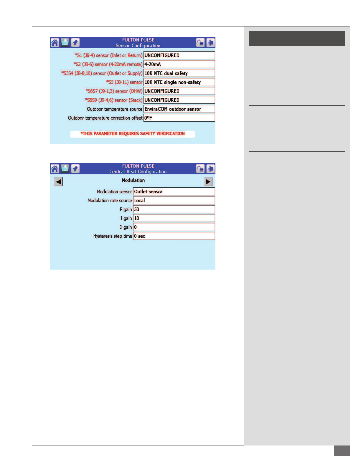
SECTION 3 PHW-IOM-2013-0214 OPERATION
! CAUTION
All information in this manual is for
reference and guidance purposes,
and does not substitute for required
professional training, conduct,
and strict adherence to applicable
jurisdictional/professional codes and
regulations.
Non-Fulton product information is for
reference purposes only. No Fulton
document may substitute for full
review of documentation available
from the component manufacturer.
FIGURE 33 - SENSOR CONFIGURATION SCREEN
FIGURE 34 - MODULATION
than what may be required. The boiler will shut o at this setpoint if
remote contacts are not opened.
NOTE: ´ Selecting Burner On/O will require remote on/o (stop/start) contacts.
¡ Procedure for Remote Setpoint Using a 4-20mA Signal (Single
Boiler)
1. From the Status Summary Screen press Con g, arrow down to and press
Sensor Con guration. Choose S2 (J8-6) Sensor, this will require the
sola password. Choose 4-20mA. See Figure 33. This will also require a
veri cation. See High Water Temperature Limit section for veri cation
steps.
2. In Central Heat Con guration in the Modulation screen, the Modulation
Rate Source must be Local. See Figure 34.
3. In Central Heat Con guration in the Setpoint screen, change Setpoint
source to S2 (J8-6) 4-20mA; and change the 4mA Water Temperature and
20mA Water Temperature to the required setting. See Figure 35.
Questions? Call (315) 298-5121, or visit us online at www.fulton.com
3-13

OPERATION PHW-IOM-2013-0214 SECTION 3
! WARNING
All information in this manual is for
reference and guidance purposes,
and does not substitute for required
professional training, conduct,
and strict adherence to applicable
jurisdictional/professional codes and
regulations.
Non-Fulton product information is for
reference purposes only. No Fulton
document may substitute for full
review of documentation available
from the component manufacturer.
FIGURE 35 CHANGING SETPOINT IN CENTRAL HEAT CONFIGURATION SCREEN
¡ Procedure for Lead/Lag with Outdoor Reset with Multiple Boilers
Items required:
§ One Supply Header Sensor Kit. Kit to include Thermowell, 2x4” Handy
Box and clip to attach thermowell to handy box
§ One Outdoor Sensor and Interface Module Kit. Kit to include outdoor
sensor, NEMA 4 box, squeeze connector for sensor and interface
Module. Interface Module must be mounted on the other side of the
wall (inside the building) from outdoor sensor this will ensure it is as
close to the sensor as possible.
4. Speci c parameter changes that are required will prompt you for a password,
the password is sola. Also some of the changes will require a Veri cation of your
change. The Veri cation process can be accomplished after all the changes are
made.
NOTE: ´ See Figure 51 for diagram of boilers in a lead/lag outdoor reset
application.
Proceed as follows:
1. From the Status Summary page press Con gure to access the
Con guration Menu. See Figure 36.
3-14
2. For the Master Boiler in the Con guration Menu select Lead Lag Master
Con guration. Press Master enable and select Enable. Then select
Advanced Settings in the lower right of this screen. See Figure 37.
3. Master Boiler - In the Advanced Settings of Lead Lag Master Con guration
arrow over to Outdoor Reset. Press Enable and select Enabled. Also
in this screen there are 3 of your 4 points that can be chosen for your
outdoor reset curve. Maximum outdoor temperature relates to low water
© The Fulton Companies 2013

SECTION 3 PHW-IOM-2013-0214 OPERATION
temperature. Minimum outdoor temperature relates to Central Heat
Setpoint. See Figure 38. Minimum boiler water temperature should be the
lowest temperature at which you want the boiler to function.
4. Master Boiler – While still in the Advanced Settings Screen, arrow over
to Central Heat and Select your Setpoint. This is what your Minimum
outdoor temp will relate to on the curve. Once all 4 numbers are entered
FIGURE 36 - ACCESSING THE CONFIGURATION MENU
! WARNING
Non-Fulton product information is for
reference purposes only. No Fulton
document may substitute for full
review of documentation available
from the component manufacturer.
Operating this equipment beyond
its design limits can damage the
equipment and can be dangerous.
Do not operate the equipment
outside of its limits. Do not try to
upgrade the equipment performance
through unapproved modi cations.
Unapproved modi cations may
cause injury, equipment damage, and
will void the warranty.
FIGURE 37 - ADVANCED SETTINGS
FIGURE 38 - OUTDOOR RESET
Questions? Call (315) 298-5121, or visit us online at www.fulton.com
3-15

OPERATION PHW-IOM-2013-0214 SECTION 3
! WARNING
Do not operate, or allow others
to operate, service or repair this
equipment unless you (they) fully
understand all applicable sections
of this manual and are quali ed to
operate/maintain the equipment.
Non-Fulton product information is for
reference purposes only. No Fulton
document may substitute for full
review of documentation available
from the component manufacturer.
you can look at your curve in the previous screen, press Show Line. See
Figure 39.
5. Master Boiler – While still in the Advanced Settings Screen arrow over to
Warm Weather Shutdown. If required, Select Enable and press Shutdown
after demand ends. Then select the Setpoint (outside air temperature) at
which you want the system to shut down. See Figure 40.
FIGURE 39 - SELECTING CENTRAL HEAT SETPOINT
3-16
FIGURE 40 - WARM WEATHER SHUTDOWN
6. For the Master Boiler, back out to the Con guration Menu, select Lead Lag
Slave Con guration and select Slave Enable - Enable slave for built-in Lead
Lag Master. See Figure 41.
FIGURE 41 - LEAD LAG SLAVE CONFIGURATION
© The Fulton Companies 2013
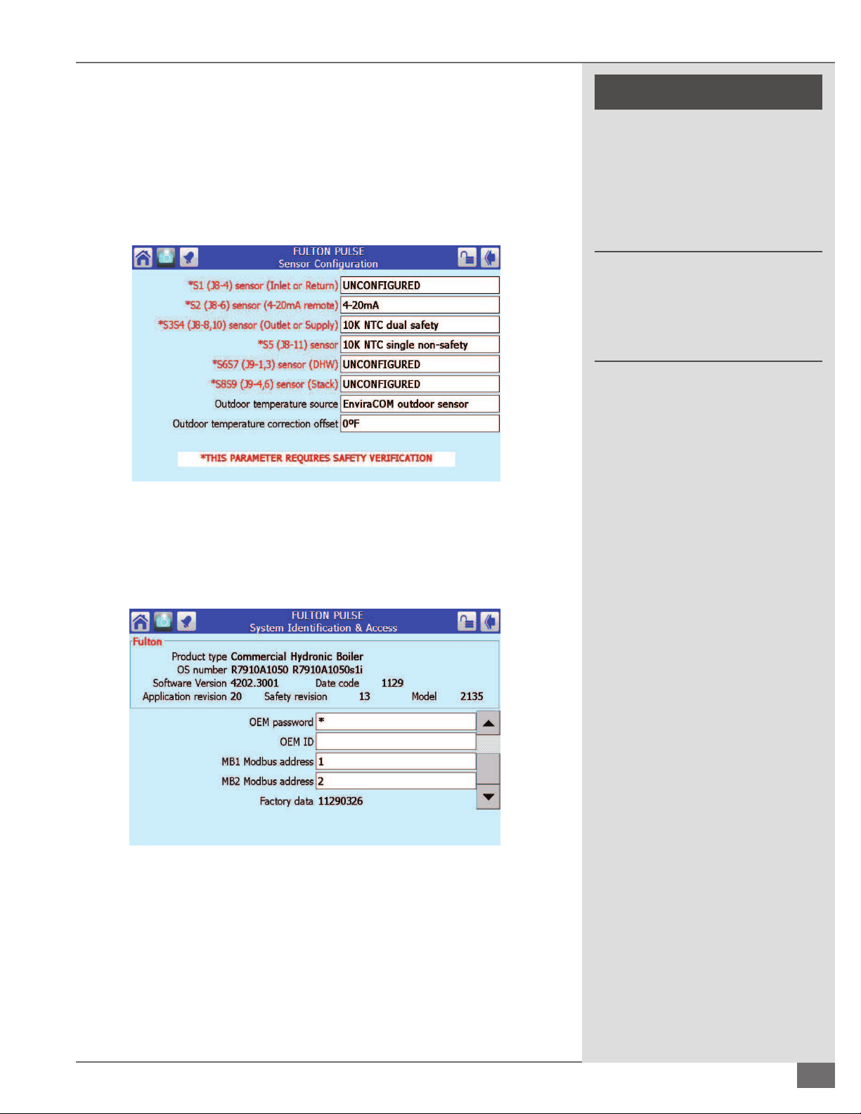
SECTION 3 PHW-IOM-2013-0214 OPERATION
7. For the Slave Boiler(s), go to the Con guration Menu, select Lead Lag Slave
Con guration and select Slave Enable - Enable slave for built-in Lead Lag
Master. See Figure 41.
8. Master Boiler - Sensor Selection: In the Con guration Menu go to Sensor
Con guration. Press sensor Outdoor temperature source, select Enviracom
Outdoor Sensor. Also change S5 (J8-11) sensor to 10K NTC single nonsafety, this is your header sensor. See Figure 42.
FIGURE 42 - SENSOR CONFIGURATION
! WARNING
All information in this manual is for
reference and guidance purposes,
and does not substitute for required
professional training, conduct,
and strict adherence to applicable
jurisdictional/professional codes and
regulations.
Non-Fulton product information is for
reference purposes only. No Fulton
document may substitute for full
review of documentation available
from the component manufacturer.
9. Master and Slave Boiler - Back out to the Con guration Menu and select
System Identi cation and Access. See Figure 43. This is where the address
of each boiler will be selected at MB1 Modbus Address. The boilers will be
daisy chained to each other through MB1 on the base of the
FIGURE 43 - SYSTEM IDENTIFICATION AND ACCESS
control. The master boiler will be address 1 as shown in Figure 42. The
next “slave” boilers will be 2,3,4… depending on the amount of boilers.
Each boiler will have its own address.
10. Perform veri cation of changes. See Figure 44.
Questions? Call (315) 298-5121, or visit us online at www.fulton.com
3-17

OPERATION PHW-IOM-2013-0214 SECTION 3
! WARNING
All information in this manual is for
reference and guidance purposes,
and does not substitute for required
professional training, conduct, and strict
adherence to applicable jurisdictional/
professional codes and regulations.
Non-Fulton product information is
for reference purposes only. No Fulton
document may substitute for full review
of documentation available from the
component manufacturer.
FIGURE 44 - VERIFICATION OF CHANGES
¡ Single Boiler Outdoor Reset Programming
1. From the status summary screen press Con gure. Press CH- Central
Heat Con guration. See Figure 45.
FIGURE 45 - ACCESSING CENTRAL HEAT CONFIGURATION
2. Arrow over to Setpoint and verify that the Setpoint is the desired
temperature in relation to the Minimum outdoor temperature (see
Figures 46 and 47).
3-18
3. Arrow over to the Central Heat page (Figure 47). In this screen 3 of your
4 points that can be chosen for your outdoor reset curve. Maximum
outdoor temperature which relates to your Low water temperature
and your Minimum outdoor temperature relates to your Central
Heat Setpoint in the setpoint screen. Your Minimum boiler water
temperature should be the lowest temperature at which you want the
boiler to operate.
© The Fulton Companies 2013

SECTION 3 PHW-IOM-2013-0214 OPERATION
! WARNING
All information in this manual is for
reference and guidance purposes,
and does not substitute for required
professional training, conduct, and strict
adherence to applicable jurisdictional/
professional codes and regulations.
Non-Fulton product information is
for reference purposes only. No Fulton
document may substitute for full review
of documentation available from the
component manufacturer.
FIGURE 46 - VERIFYING SETPOINT
FIGURE 47 - OUTDOOR RESET CONFIGURATION
4. By pressing Show Line in the Outdoor Reset Con guration screen you can
see outdoor temperatures in relation to your water temperatures in a linear
format. See Figure 48.
FIGURE 48 - CENTRAL HEAT OUTDOOR RESET
Questions? Call (315) 298-5121, or visit us online at www.fulton.com
3-19

OPERATION PHW-IOM-2013-0214 SECTION 3
! WARNING
All information in this manual is for
reference and guidance purposes,
and does not substitute for required
professional training, conduct, and strict
adherence to applicable jurisdictional/
professional codes and regulations.
Non-Fulton product information is
for reference purposes only. No Fulton
document may substitute for full review
of documentation available from the
component manufacturer.
5. Back out to the Con gure Screen and press Sensor Con guration. The
“sola” password will need to be entered. Press the Outdoor temperature
source and choose EnviraCOM outdoor source. See Figure 49.
NOTE: ´ The 1ea (KIT) 2-40-001072, outdoor sensor and Interface Module is
required, wired to the Sola base ECOM terminals 1,2, and 3.
FIGURE 49 - SENSOR CONFIGURATION
6. Back out to the Con gure menu and press Verify and complete the
veri cation process. See Figure 50.
FIGURE 50 - VERIFICATION
3-20
© The Fulton Companies 2013

SECTION 3 PHW-IOM-2013-0214 OPERATION
Third Party SOLA Control
The Pulse SOLA Control provides the capability of control
and/or monitoring by a third party. The standard SOLA control
protocol is Modbus.
¡ Lead/Lag Outdoor Reset Confi guration Using
Communication Port 2
If the boilers are set up to be lead/lag with outdoor reset
all the communication connections on the J3 plug of the
SOLA control will be used. Third party control can be wired
to the SOLA display on communication port 2. If requested
at the time of the boiler order, the communication port will
be activated at the factory. Only the baud rate may have to
be changed in the eld. When the boilers are con gured
for lead/lag outdoor reset, only the master boiler needs
to have the third party connection. Multiple points of the
lag boilers can be viewed from the Master boiler. Refer to
Figure 52. Figure 52 shows wiring connection to the display’s
communication port 2. Use the website link and/or QR code
in this section of the manual to access additional information
on setting up the communication port 2.
¡ Gateways
Fulton o ers (as an option) a Modbus to Bacnet gateway.
The gateway will come pre-programmed and wired in one,
or if desired, all of the boilers. If the boilers are daisy chained
together through J3, MB1 one gateway can be used on the
master boiler which will be wired to communication port 2
of the master display. Use the website link and/or QR code
in this section of the manual to access additional information
on pre-programmed gateway information (read and write
addresses) and setup instructions.
NOTE: ´ Although there are many points that are available
through Modbus, special care must be taken when writing
to them. There are speci c write addresses that will utilize
an internal Sola control EEPROM. The Sola control requires
a write command only when the user intends to change a
value. Continuously writing to the control will ll the SOLA’s
EEPROM memory, causing various non-safety parameters to
change. All of the information out of the control is in Celsius;
this may have to be converted to Fahrenheit if desired. Firing
rate also requires a conversion. Please refer to the website link
and QR code for more information.
¡ Stand Alone Boilers Controlled by a Third Party
Control
If the boilers are not set up to be lead/lag outdoor reset, a
third party control can land connection to J3, MB1 on the
SOLA control. If this is known at the time the boiler order
is entered, the control will be set up for this type of control.
Please refer to Figure 52 for J3, MB1 connections. The
communication wires can be daisy chained to each boiler. Use
the website link and/or QR code in this section of the manual
to access additional information on setting up the MB1.
} WEB ADDRESS FOR FURTHER INFORMATION
http://goo.gl/O8I7U
Questions? Call (315) 298-5121, or visit us online at www.fulton.com
3-21

OPERATION PHW-IOM-2013-0214 SECTION 3
J3 ECOM 1,2,3
For Outdoo r
Sensor Inte rface
Module
J8 (S5) terminal s
11 & 12 For
Header Se nsor
POWER
FLAME
ALARM
RESET
2-40-000907
BOILER
Master
A B C
J3 (MB1) A,B,C
For daisy chain of
boilers
Com 1 and 24
VAC of the
display will be
pre-wired at the
factory
S7999D
Display
POWER
FLAME
ALARM
RESET
2-40-000907
BOILER
Lag
A B C
J3 (MB1) A,B,C
For daisy chain of
boilers
Com 1 and 24
VAC of the
display will be
pre-wired at the
factory
S7999D
Display
POWER
FLAME
ALARM
RESET
2-40-000907
BOILER
Lag
A B C
J3 (MB1) A,B,C
For daisy chain of
boilers
Com 1 and 24
VAC of the
display will be
pre-wired at the
factory
S7999D
Display
COM 1 1 COM 2 24 VAC
A B CA B C COM POWER
COM 1 1 COM 2 24 VAC
A B CA B C COM POWER
COM 1 1 COM 2 24 VAC
A B CA B C COM POWER
Clamp
Filter
TE
Water Header
Honeywell Header
Sensor and Well
Outdoor Sensor Interface Module
1 2 3 OT OT
Communication wire, Modbus for BMS
RS-4 85 message forma t:
1 start bi t
8 data bits
No parit y bit
1 stop bit
Note: If boi lers are daisy chan ied together onl y one BMS
connect ion is required to th e master.
Communica tion wire
Outside
Wall
Outdoor Sensor
Interface Module,
mounted inside as
close to outdoor
sensor as possible
Honeywell Sensor and Well
Outside Air Sensor
2 wire, landed on
“OT” of interface
Module, Field Wiring
Outdoor Sensor
1
3 Wires Connected to Master Boiler
(J3 ECOM terminals 1,2 and 3), Field Wiring
2
Field Wiring
3
Clamp Filter all connections to D display
4
4
3
1
2
Header Sensor
3-22
FIGURE 51 - LEAD/LAG OF HYDRONIC BOILERS USING THE SOLA CONTROL (MAXIMUM OF 8 BOILERS)
© The Fulton Companies 2013

SECTION 3 PHW-IOM-2013-0214 OPERATION
Questions? Call (315) 298-5121, or visit us online at www.fulton.com
FIGURE 52 - EXAMPLE/TYPICAL
ELECTRICAL DIAGRAM
3-23

OPERATION PHW-IOM-2013-0214 SECTION 3
3-24
© The Fulton Companies 2013

MAINTENANCE
INTRODUCTION
INSTALLATION
1
2
OPERATION
MAINTENANCE
WARRANTY & PARTS
3
4
5
Questions? Call (315) 298-5121, or visit us online at www.fulton.com
4-1

MAINTENANCE PHW-IOM-2013-0214 SECTION 4
! WARNING
All information in this manual is for
reference and guidance purposes,
and does not substitute for required
professional training, conduct,
and strict adherence to applicable
jurisdictional/professional codes and
regulations.
Prior to any maintenance concerning
electrical components of this
equipment, ensure electrical supply
to the equipment is disconnected.
Label all wires prior to disconnection;
wiring errors may cause improper
and hazardous operation.
Follow all proper lockout/tagout
procedures for service.
Before beginning any maintenance,
ensure area is free of any combustible
materials and other dangers.
General
Your Pulse boiler has been designed to provide years of trouble free
performance. To ensure continued safety and e ciency of the boiler, please
follow the maintenance and inspection directions outlined in this section of the
manual.
Daily, Weekly and Monthly Maintenance and Inspection (Fulton considers the
following to be good practice for any boiler, and is applicable to the full line of
Pulse boilers).
1. Before each heating season, check the following:
§ Air intake and exhaust vent outlet for blockage or restrictions
§ Exhaust piping for leaks
§ Heating system or boiler piping for leaks
§ Air intake and exhaust vent piping for sagging
2. Follow the purge procedure outlined in this manual.
3. Follow the Start-Up Procedure outlined in this manual.
4. With the boiler running, check for cracks at ttings and joints.
What to do if you smell gas:
Do not try to light the appliance.
Do not touch any electrical switch.
Do not use any phone in the building.
Leave building and contact gas
supplier from neighbor’s phone. If you
cannot reach gas supplier, phone the
re department.
After initial start-up by quali ed
personnel, linkage, control settings,
and fuel pressures should not be
readjusted.
4 CAUTION
All maintenance procedures should
be completed by trained personnel.
Appropriate training and instructions
are available from the Fulton Service
Department at (315) 298-5121 or your
local Fulton Thermal Representative.
Daily Maintenance and Inspection Schedule
Daily maintenance and inspection must include the following:
1. Observe operating temperature and general conditions.
2. Make sure that the ow of combustion and ventilating air to the boiler is
not obstructed.
3. Make sure boiler area is free and clear of any combustible materials,
including ammable vapors and liquids.
Monthly Maintenance and Inspection Schedule
Monthly maintenance and inspection must include the following:
1. Inspect the air intake and exhaust vent pipes for broken seals at the joints.
2. Inspect the screens on the air intake and exhaust vent terminal and
make sure they are free of dirt or any foreign matter which may block the
terminals.
3. Check air intake and exhaust vent outlet for any blockage or restrictions.
In order to meet warranty conditions,
ensure all appropriate maintenance
activities are performed.
4-2
4. Check for any leaks in exhaust piping.
5. To prevent scale or corrosion in boiler and associated piping, make up
water must be kept to a minimum. This is best achieved by ensuring:
© The Fulton Companies 2013

SECTION 4 PHW-IOM-2013-0214 MAINTENANCE
§ Immediate repair of all leaks.
§ Maintenance of system pressure.
6. Check condensate trap to be sure it is clear of debris. Also ensure
condensate is not backing up into the boilers.
Annual Maintenance and Inspection Schedule
Annual maintenance and inspection must include the following:
1. On units utilizing a ame rod, the ame rod should be changed. The ame
rod is located in the top of the boiler for PHW-300-1400, and inside the
injector on PHW-2000.
2. Clean/replace apper valve gaskets.
3. Verify proper combustion and adjust as necessary.
4. Lubricate the modulation motor arms, gas and exhaust butter y valves.
Ensure the motion of the valves is smooth.
5. Remove the low water cut o probe and clean. Replace the probe in the
boiler.
! WARNING
All information in this manual is for
reference and guidance purposes,
and does not substitute for required
professional training, conduct,
and strict adherence to applicable
jurisdictional/professional codes and
regulations.
Never use open ame or other sources
of ignition to check for gas leaks.
A defective boiler can cause injury.
Do not operate a boiler that is
defective, or has any missing parts.
Do not attempt repairs or any other
maintenance work that you do not
understand.
Never store or use gasoline or other
ammables in the vicinity of this
appliance.
6. Change the spark plug (see Figures 53 and 54).
7. Check air intake and exhaust vent outlet for any blockage or restrictions.
8. Check for any leaks in exhaust piping.
9. Check for any leaks in the heating system or boiler piping.
10. Check the air intake and exhaust vent piping for sagging.
11. Follow purge procedure outlined in this manual.
12. Follow start up procedure outlined in this manual.
13. With the boiler running, check for visible cracks at ttings and joints.
14. Check for any blockages in condensate lines, and condensate trap. If a pH
Neutralization Kit has been installed, check quantity of media in kit.
NOTE: ´ Should you suspect that the boilers ue passage ways have become
blocked, contact your Fulton representative.
NOTE: ´ On models PHW300 through PHW1400 the spark plug is located in the top
of the boiler. In PHW2000 the spark plug is located in the gas injector behind the
air apper, and requires a spark plug removal tool, which is supplied with each
PHW2000.
Do not use this boiler if any part has
been under water. Immediately call a
quali ed service technician.
4 CAUTION
Use caution when using any cleaning
solutions. Refer to local regulations for
proper cleaning solution disposal.
Do not allow oil leaks, dust, or dirt to
accumulate around the boiler.
NOTE: ´ Pulse hydronic loops should be con gured so that each boiler does not
cycle more than 12,000 times per year. Warranty may be void if excessive cycling
is apparent.
Questions? Call (315) 298-5121, or visit us online at www.fulton.com
4-3

MAINTENANCE PHW-IOM-2013-0214 SECTION 4
4 CAUTION
All information in this manual is for
reference and guidance purposes,
and does not substitute for required
professional training, conduct,
and strict adherence to applicable
jurisdictional/professional codes and
regulations.
All maintenance procedures should
be completed by trained personnel.
Appropriate training and instructions
are available from the Fulton Service
Department at (315) 298-5121 or your
local Fulton Representative.
In order to meet warranty conditions,
ensure all appropriate maintenance
activities are performed.
FIGURE 53 - PULSE SPARK PLUG
4-4
FIGURE 54 - PULSE MAINTENANCE
After All Repairs and Maintenance
1. Follow “Pre-Start Check List” provided with the unit, and all Safety Checks.
2. Fire the Boiler and perform combustion check.
3. Make any necessary adjustments.
© The Fulton Companies 2013
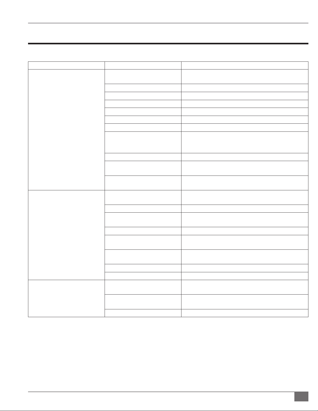
SECTION 4 PHW-IOM-2013-0214 MAINTENANCE
Troubleshooting
Use the following table as a guide to troubleshooting your boiler.
Problem Cause Check
Check fuse or circuit breaker. Reset or replace, as neces-
sary.
For all models check to see if on/off switch has loose wires.
Try adjusting sensitivity of switch or replace.
Check fan for operation. Replace if necessary.
Check for carbon buildup, cracks in porcelain.
Check for bad ground, or bad control. Replace control.
Check for blockage of air inlet line and remove.
Check for carbon buildup, moisture, cracks in porcelain.
Check for proper gab (.050”-.060” for Champion spark
plug). Clean or replace as necessary.
Check connections to all components.
Check that the setpoint is set higher than temperature of
the boiler water.
Check to see if the copper tubing on the air valve housing
is securely connected.
Check fuse or circuit breaker. Reset or replace, as neces-
sary.
Check for bad ground, or bad control. Replace control.
Check adjustment of pressure switch number 2. It should
be set at 1.5” w.c. Replace if necessary.
Check connections to all components.
Check to see if the fl appers on the air valve plate are
placed correctly (covering the holes).
Check to see if the fl appers on the gas valve plate are
placed correctly (covering the holes).
Check for blockage in exhaust piping and remove.
Reset main control panel box on fl ame failure.
Check to see if the fl appers on the air valve plate are
placed correctly (covering the holes).
Check to see if the fl appers on the gas valve plate are
placed correctly (covering the holes).
Check for blockage in air inlet line and remove.
Starting or Purge Failure
Flame Failure
Poor Combustion
Power Supply
On/Off Switch
Bad Air Switch
Bad Fan
Flame Rod
Main Control
Plugged Air Inlet
Spark Plug
Loose Wire Connection
Setpoint
Loose Tubing
Power Supply
Main Control
Proof of Flame Switch
Loose Wire Connection
Air Flappers
Gas Flappers
Plugged Exhaust Line
In all Cases:
Air Flappers
Gas Flappers
Plugged Air Inlet
NOTE: ´ If air or gas apper material is excessively dirty, they may stick in one position. Replace if excessively dirty.
Questions? Call (315) 298-5121, or visit us online at www.fulton.com
4-5

MAINTENANCE PHW-IOM-2013-0214 SECTION 4
4 CAUTION
All information in this manual is for
reference and guidance purposes,
and does not substitute for required
professional training, conduct, and strict
adherence to applicable jurisdictional/
professional codes and regulations.
All maintenance procedures should
be completed by trained personnel.
Appropriate training and instructions
are available from the Fulton Service
Department at (315) 298-5121 or your local
Fulton Representative.
In order to meet warranty conditions, ensure
all appropriate maintenance activities are
performed.
Reviewing Diagnostics on SOLA Control
From the Status Summary screen press Diagnostics (see Figure 55) .
FIGURE 55 - ACCESSING DIAGNOSTICS
1. Pressing Burner I/O will place you into screen shown in Figure 56. From
here you can see the inputs being made and/or are open. A green light
next to the input indicates the control’s input is made or satis ed, a gray
circle indicates the input is not satis ed. This is also a helpful trouble
shooting screen.
4-6
FIGURE 56 - I/O STATUS SCREEN
2. Pressing Digital I/O will place you into screen shown in Figure 57. From
here you can see speci c information what inputs are/are not being made.
© The Fulton Companies 2013

SECTION 4 PHW-IOM-2013-0214 MAINTENANCE
4 CAUTION
All information in this manual is for
reference and guidance purposes,
and does not substitute for required
professional training, conduct, and strict
adherence to applicable jurisdictional/
professional codes and regulations.
All maintenance procedures should
be completed by trained personnel.
Appropriate training and instructions
are available from the Fulton Service
Department at (315) 298-5121 or your local
FIGURE 57 - I/O STATUS DETAIL
¡ Taking Screen Shots
Using the Screen Shot function of the SOLA control can be a useful tool for
troubleshooting. A USB port in the back of the display will accept a small
memory stick or thumb drive for transferring screen shots from the display.
Fulton Representative.
In order to meet warranty conditions, ensure
all appropriate maintenance activities are
performed.
FIGURE 58 - ACCESSING SETUP
At most locations in the display parameters, there is an icon of a camera in
the upper left of the screen. By pressing this icon, a snapshot of the screen is
captured and saved to the display. To transfer these snapshots to a memory stick
or thumb drive, perform the following:
1. From the Home Screen, press Setup in the lower right hand corner. See
Figure 58.
2. Press Display Diagnostics. See Figure 59.
3. Press Screen Snapshot. See Figure 60. This is the screen from which you
can copy screen shots to a thumb drive.
Questions? Call (315) 298-5121, or visit us online at www.fulton.com
4-7

MAINTENANCE PHW-IOM-2013-0214 SECTION 4
4. Select an existing screen shot in the list and then select
Copy to USB. Selecting View allows you to look at a
particular screen shot before you copy it. See Figure 61.
FIGURE 61 - SCREEN SNAPSHOT LIST SCREEN
FIGURE 59 - SETUP SCREEN
4-8
FIGURE 60 - DISPLAY DIAGNOSTICS SCREEN
© The Fulton Companies 2013

WARRANTY & PARTS
INTRODUCTION
INSTALLATION
1
2
OPERATION
MAINTENANCE
WARRANTY & PARTS
3
4
5
Questions? Call (315) 298-5121, or visit us online at www.fulton.com
5-1

WARRANTY & PARTS PHW-IOM-2013-0214 SECTION 5
Standard Warranty for Fulton Pulse Boilers
Models PHW with Carbon Steel Exhaust Pipes
Ten (10) Year (120 Month) Thermal Shock Warranty
Fulton Heating Solutions guarantees the Pulse hot water pressure vessel against thermal shock for a period of ten (10) years
when the boiler is installed as a closed loop hot water boiler and is operated per the Installation and Operation Manual. This
guarantee will cover damage due to thermal shock, such as leaks in the heat exchanger. This guarantee does not cover damage
due to corrosion, scaling, sooting or improper installation or operation. The inlet and outlet water temperature di erential across
the boiler cannot exceed 100°F.
Ten (10) Year (120 Month) Prorated Flue Gas Condensate Corrosion and Material and Workmanship Warranty
The pressure vessel is covered against ue gas condensate corrosion and defective material or workmanship for a period of
ten (10) years from the date of shipment from the factory according to the schedule below. Fulton will repair or replace F.O.B.
factory any part of the equipment, as de ned above, provided this equipment has been installed, operated and maintained by
the buyer in accordance with approved practices and recommendations made by Fulton. The commissioning agency must also
successfully complete and return the equipment Installation and Operation Checklists to Fulton’s Quality Assurance department.
This warranty covers any failure caused by defective material or workmanship; however, waterside corrosion or scaling is not
covered. Therefore, it is imperative that the boiler be installed in a closed loop as outlined in the Installation and Operation
Manual.
Year Prorated Schedule
0-7 100%
8 50%
9 30%
10 20%
Parts Warranty
Fulton will repair or replace F.O.B. factory any part of the equipment of our manufacture that is found to be defective in
workmanship or material within 18 months of shipment from the factory or 12 months from start-up (whichever comes rst),
provided the equipment has been installed, operated and maintained by the buyer in accordance with approved practices and
recommendations made by both Fulton and the component manufacturers and the commissioning agency has successfully
completed and returned the equipment Installation and Operation Checklists to Fulton’s Quality Assurance Department.
General
Fulton shall be noti ed in writing as soon as any defect becomes apparent. This warranty does not include freight, handling or
labor charges of any kind. These warranties are contingent upon the proper sizing, installation, operation and maintenance of
the boiler and peripheral components and equipment. Warranties valid only if installed, operated, and maintained as outlined
in the Fulton Installation and Operation Manual. No Sales Manager or other representative of Fulton other than the Quality
Manager or an o cer of the company has warranty authority. Fulton will not pay any charges unless they were pre-approved,
in writing, by the Fulton Quality Manager. This warranty is exclusive and in lieu of all other warranties, expressed or implied,
including but not limited to the implied warranties of merchantability and tness for a particular purpose. Fulton shall in no
event be liable for any consequential or incidental damages arising in any way, including but not limited to any loss of pro ts or
business, even if the Fulton Companies has been advised of the possibility of such damages. Fulton’s liability shall never exceed
the amount paid for the original equipment found to be defective. Excessive cycling will reduce the life of ANY boiler. Verify that
your system is properly designed and check cycling rate according to maintenance procedures listed in this manual. To activate
the warranty for this product, the appropriate commissioning sheets must be completed and returned to the Fulton Quality
Assurance department for review and approval.
2013-0214
5-2
© The Fulton Companies 2013

SECTION 5 PHW-IOM-2013-0214 WARRANTY & PARTS
Standard Warranty for Fulton Pulse Boilers
Models PHW with Duplex Stainless Steel Exhaust Pipes
Ten (10) Year (120 Month) Thermal Shock Warranty
Fulton Heating Solutions guarantees the Pulse hot water pressure vessel against thermal shock for a period of ten (10) years
when the boiler is installed as a closed loop hot water boiler and is operated per the Installation and Operation Manual. This
guarantee will cover damage due to thermal shock, such as leaks in the heat exchanger. This guarantee does not cover damage
due to corrosion, scaling, sooting or improper installation or operation. The inlet and outlet water temperature di erential across
the boiler cannot exceed 100°F.
Ten (10) Year (120 Month) Prorated Flue Gas Condensate Corrosion and Material and Workmanship Warranty
The pressure vessel is covered against ue gas condensate corrosion and defective material or workmanship for a period of
ten (10) years from the date of shipment from the factory according to the schedule below. Fulton will repair or replace F.O.B.
factory any part of the equipment, as de ned above, provided this equipment has been installed, operated and maintained by
the buyer in accordance with approved practices and recommendations made by Fulton. The commissioning agency must also
successfully complete and return the equipment Installation and Operation Checklists to Fulton’s Quality Assurance department.
This warranty covers any failure caused by defective material or workmanship; however, waterside corrosion or scaling is not
covered. Therefore, it is imperative that the boiler be installed in a closed loop as outlined in the Installation and Operation
Manual.
Year Prorated Schedule
0-7 100%
8 50%
9 30%
10 20%
Parts Warranty
Fulton will repair or replace F.O.B. factory any part of the equipment of our manufacture that is found to be defective in
workmanship or material within one (1) year of shipment from the factory provided this equipment has been installed, operated
and maintained by the buyer in accordance with approved practices and recommendations made by both Fulton and the
component manufacturers and the commissioning agency has successfully completed and returned the equipment Installation
and Operation Checklists to Fulton’s Quality Assurance department.
General
Fulton shall be noti ed in writing as soon as any defect becomes apparent. This warranty does not include freight, handling or
labor charges of any kind. These warranties are contingent upon the proper sizing, installation, operation and maintenance of
the boiler and peripheral components and equipment. Warranties valid only if installed, operated, and maintained as outlined
in the Fulton Installation and Operation Manual. No Sales Manager or other representative of Fulton other than the Quality
Manager or an o cer of the company has warranty authority. Fulton will not pay any charges unless they were pre-approved,
in writing, by the Fulton Quality Manager. This warranty is exclusive and in lieu of all other warranties, expressed or implied,
including but not limited to the implied warranties of merchantability and tness for a particular purpose. Fulton shall in no
event be liable for any consequential or incidental damages arising in any way, including but not limited to any loss of pro ts or
business, even if the Fulton Companies has been advised of the possibility of such damages. Fulton’s liability shall never exceed
the amount paid for the original equipment found to be defective. Excessive cycling will reduce the life of ANY boiler. Verify that
your system is properly designed and check cycling rate according to maintenance procedures listed in this manual. To activate
the warranty for this product, the appropriate commissioning sheets must be completed and returned to the Fulton Quality
Assurance department for review and approval.
2010-0311
Questions? Call (315) 298-5121, or visit us online at www.fulton.com
5-3

PARTS & WARRANTY PHW-IOM-2013-0214 SECTION 5
! WARNING
Use of non-factory authorized
replacement parts is not recommended
for this equipment. Use of non-factory
authorized parts may jeopardize safety
and system performance, and voids the
product warranty.
Parts
Spare and replacement parts may be ordered from your local representative or
through the Fulton Companies. When ordering replacement parts, please have
the model number and serial number of your Fulton boiler ready. Factory-direct
replacement parts must be used to ensure proper equipment operation and
adherence with warranty requirements. Contact Fulton Companies at (315) 2985121 for further information.
Parts list and availability subject to change without prior notice.
5-4
© The Fulton Companies 2012

SECTION 5 PHW-IOM-2013-0214 WARRANTY & PARTS
¡ PARTS
PHW Part # Description
2-30-000232 Air switch-purge fan
2-30-001334 Air switch -proof of fl ame x x x x x x x x
2-30-000290 Blocked intake switch x x
2-30-000291 Blocked intake switch x x x x
2-30-001360 Blocked exhaust switch x x x x x x x x
2-12-000551 Air fl apper gaskets (replaced 2-12-553) x x x x x x x
2-12-000554 Air fl apper gaskets x
2-22-000181 Air fl apper spacer - .030 x x x x x
2-22-000182 Air fl apper spacer - .050
2-22-000183 Air fl apper spacer - .040
2-22-000186 Air fl apper spacer - .060 x LP
2-22-000187 Air fl apper spacer - .060 x
2-22-000188 Air fl apper spacer - .070
2-22-000125 Air fl apper screw 8-32 x 1-1/4 x x x x x x x x
2-22-000085 Air fl apper nuts 8-32 x x x x x x x x
2-22-000038 Air fl apper lock washer x x x x x x x x
2-22-000083 AVK Nut for air fl apper assy
2-12-000900 Air fl apper mounting gaskets x
7-37-000120 Air fl apper metering plate assy x
7-37-000150 Air fl apper metering plate assy x x
7-37-000124 Air fl apper metering plate assy x
7-37-000123 Air fl apper metering plate assy
7-37-000125 Air fl apper metering plate assy
7-37-000008 Air fl apper metering plate assy
2-11-000089 Air fl apper housing only - 3” hub x x
2-11-000090 Air fl apper housing only - 4” hub x x x x x
5-11-000095 Air fl apper housing only x
2-12-000556 Air fl apper housing o-ring x x x x x x x x
2-40-000251 Aquastat Operating x x x x x x x x
2-40-000250 Aquastat Hi Limit w/MR 130-270 Deg F x x x x x x x x
2-30-000205 Aquastat immersion well - #121371A x x x x x x x x
2-40-000274 Aquastat Hi Limit w/MR 100-240 Deg F x x x x x x x
2-40-000294 Aquastat Hi Limit w/MR 100-200 Deg F
2-40-000220 Gas valve actuator w/P.O.C. - #V4055D1043
2-40-000214 Gas valve actuator - #V4055A1031 x x x x x x x x
2-30-000310 Gas valve - motorized - 1” - #V5055A1004 x x x x
2-30-000311 Gas valve - motorized - 1-1/4” - #V5055A1012 x x
2-30-001143 Gas valve - motorized - 1-1/2” - #V5097A1004 x x
2-30-001145 Gas valve - motorized - 1-1/2” - #V5097C1000 x x
300 500 650 750 950 1000 1400 2000
x x x x x x x x
x/LP
x x x x x x x x
x
x x
x
x x x x x x x
x x x x x x x x
Questions? Call (315) 298-5121, or visit us online at www.fulton.com
5-5

WARRANTY & PARTS PHW-IOM-2013-0214 SECTION 5
PHW Part # Description
Gas valve w/P.O.C. - motorized - 1-1/2” -
2-40-000253
2-30-000306 Gas solenoid valve - 1” ASCO #8040C4 x x x x
2-30-000307 Gas solenoid valve - 1-1/4” ASCO #8040C5 x x
2-30-000304 Gas solenoid valve - 1-1/2” ASCO #821470 x
2-30-001147 Gas solenoid valve - 1” #V4297A1005 x x x
2-30-001141 Gas solenoid valve - 1-1/2” #V4297A1013 x
2-40-000533 Hi-Low Gas Pressure Switch #804111701
2-30-001139 High Gas Pressure Switch - #C6097B1028 x x x x x x x x
2-30-001140 Low Gas Pressure Switch - #C6097A1020 x x x x x x x x
2-30-003002 Gas butterfl y valve - 1” - Eclipse x x x x
2-30-003003 Gas butterfl y valve - 1-1/4” - Eclipse x x x
2-30-003020 Gas butterfl y valve - 2” - Eclipse x
2-30-000750 Gas pressure regulator - 1” RV61 - Pre 3/10 x x x x
2-30-000105 Gas pressure regulator - 1-1/4” RV61 -Pre 3/10 x x
2-30-000515 Gas pressure regulator - 1-1/4” RV81 -Pre 3/10 x
2-30-000516 Gas pressure regulator - 1-1/2” RV81 -Pre 3/10 x x
2-30-000800 Gas pressure regulator - 1” 210D - Post 3/10
2-30-000678 Gas pressure regulator - 1-1/4” 210D-Post 3/10
2-30-001023 Gas pressure regulator -1-1/2” 210E-Post 3/10
2-30-000174 Gas pressure gauge 0-15” W.C. x x x x x x
7-37-000201 Gas fl apper valve - in union x x x x x x x x
2-22-000130 Gas fl apper spacer .060 (brass) x x x x x x x x
2-12-000552 Gas fl apper gaskets x x x x x x x x
7-57-000126 Gas decoupler x x x
7-57-000125 Gas decoupler x x x x
2-20-000204 Gas orifi ce 3/4” x .312 LP
2-20-000130 Gas orifi ce 3/4” x .437 LP
2-20-000209 Gas orifi ce 3/4” x .460 x
2-20-000208 Gas orifi ce 3/4” x .485 x
2-20-000131 Gas orifi ce 3/4” x .500 x
2-20-000201 Gas orifi ce 3/4” x .525 x LP LP
2-20-000205 Gas orifi ce 3/4” x .540 LP
2-20-000212 Gas orifi ce 3/4” x .570 x
2-20-000202 Gas orifi ce 3/4” x .593 x
2-20-000206 Gas orifi ce 3/4” x .625
2-20-000214 Gas orifi ce 3/4” x .651 x x
2-20-000132 Gas orifi ce 3/4” x .690 x
2-20-000203 Gas orifi ce 3/4” x .718
2-20-000650 Gas orifi ce 2” x .312 LP
2-20-000651 Gas orifi ce 2” x .437 LP
2-20-000652 Gas orifi ce 2” x .460 x
2-20-000652 Gas orifi ce 2” x .460 (post 05/2003)
2-20-000653 Gas orifi ce 2” x .485 x
#V5055C1059 x
300 500 650 750 950 1000 1400 2000
x x x x
x x
x x
x
5-6
© The Fulton Companies 2013

SECTION 5 PHW-IOM-2013-0214 WARRANTY & PARTS
PHW Part # Description
2-20-000655 Gas orifi ce 2” x .500
2-20-000656 Gas orifi ce 2” x .540
2-20-000656 Gas orifi ce 2” x .540 (post 05/2003) x LP LP
2-20-000657 Gas orifi ce 2” x .525 LP
2-10-400211 Gas orifi ce 2” multi-port LP
2-10-400219 Gas orifi ce 2” multi-port x
2-10-400212 Gas orifi ce 2” multi-port x
2-10-400217 Gas orifi ce 2” multi-port x
2-10-400218 Gas orifi ce 2” multi-port LP
2-10-400216 Gas orifi ce 2” multi-port (factory) x
2-10-400222 “New style” gas orifi ce 2” multi-port x
5-10-400207 Blank brass orifi ce slug 2”
Gas injector assy (need stamped series “letter” to
7-52-002000
7-52-002001 Injector assembly - all fuels LP
7-20-006000 4” Butterfl y valve assembly - exhaust modulated x x x x x
7-20-006010 6” Butterfl y valve assembly - exhaust modulated x
7-20-006005 6” Exhaust butterfl y assy - PHW2000 QT model x
2-12-000701
2-40-000722 Mod motor - M7284Q1009 x x x x x x x x
2-40-000863 Mod temp control - UT32A x x x x
2-40-000801 Type “J” Thermocouple 4” probe
2-40-000830 Type “J” Thermocouple wire per Ft.
2-40-000384 Siemens temp control - RWF40
2-40-000386 Siemens outdoor sensor for RWF40 control
2-40-000425 Mod Temp control - #T771J1050 outsideRS x x x x x x x
2-40-000941 Outdoor Air Temp Sensor
2-30-000201 Press/temp gauge 0-100psi-70-320F x x x x x x x
2-30-000203 Press/temp gauge 0-300psi-70-320F x x x x x x x
2-30-000445 Purge blower motor/fan x x x x x x x
2-30-001337 Purge fan-G185 x
2-40-002000 Purge fan motor-1/2HP, 115/230/60/1, 3450rpm x
2-40-000321 RM7865C1007 Programmer x x x x x x x x
2-40-000268 R7847A1041 Amplifi er x x x x x x x x
2-40-000270 Base for RM7865 Programmer - #Q7800A1013 x x x x x x x x
2-40-000272
2-40-000923 SOLA Flame Control x x x x x x x x
2-40-000932 SOLA Display x x x x x x x x
2-40-000931 SOLA Flame Rod
2-45-000914 Plug Set for SOLA x x x x x x x x
2-40-000908 10K ohm Sensor x x x x x x x x
2-40-000625 24v Power Supply / Transformer x x x x x x x x
2-45-000060 4” x 4” Handy Box x x x x x x x x
2-30-000120 Safety Valve 3/4” X 1” 30# x x x x x x
2-30-000121 Safety Valve 3/4” X 1” 60# x x x x x x x
order) x
Exhaust butterfl y gasket 9” OD x 6-9/16” ID - QT
model x
Display module for RM7865 Programmer #S7800A1019 x x x x x x x x
300 500 650 750 950 1000 1400 2000
x
X
Questions? Call (315) 298-5121, or visit us online at www.fulton.com
5-7

WARRANTY & PARTS PHW-IOM-2013-0214 SECTION 5
PHW Part # Description
2-30-000145 Safety Valve 3/4” X 1” 100# x x x x x x x
2-30-000020 Safety Valve 3/4” X 1” 125# x x x x x x x x
2-30-000166 Safety Valve 3/4” X 1” 160# x x x x x x x x
2-30-000851 Safety Valve 1” X 1-1/4” 30# x
2-30-000951 Safety Valve 1” X 1-1/4” 60# x x
2-30-000269 Safety Valve -1 1/4” X 1-1/2” 160#
2-30-000266 Safety Valve 1-1/4” X 1-1/2” 60#
2-30-000221 Safety Valve 1-1/4” X 1-1/2” 30# x
2-20-000090 Spark plug x x x x x x x x
2-20-000093 Gasket for spark plug - x x x x x x x x
2-45-000017 Spark plug & Flame Rod wire per foot x x x x x x x x
2-45-000149 Wire heat cover per foot x x x x x x x x
2-45-000159 Plastic wrap per foot x x x x x x x x
2-20-000047 Spark plug boot - orange silicone x x x x x x x
2-45-001200 Spark plug crimp on connector x x x x x x x x
2-45-001124 Spark plug terminal connector x
2-30-002330 Spark plug boot w/centering ring x
4-57-000520 Spark plug connector retrofi t kit x
5-11-400090 Spark plug bushing 3/4” NPT, brass x x x x x x x x
2-40-001011 Flame rod - #C7009A1009 x x x x x x x x
2-35-000879 Flame rod bushing 1/2” x 1/8” x x x x x x x x
3-20-000090 Spark plug assembly x
2-20-002000 Porcelain ext. rod for spark plug assy x
5-10-001821 Connector for spark plug assy x
5-10-001822 Connector for fl ame rod x x x x x x x x
2-30-000234 Grommet - spark plug wire x x x x x x x
2-40-000082 Ignition transformer 115/60 - #A06SC2 x x x x x x x x
2-40-000151 Time delay relay - #KRDB420 x x x x x x x x
2-45-000469 Time delay relay base x x x x x x x x
2-45-000468 Time delay relay 5 min. 120V - #HRDM415M x x x x x x x x
2-40-000153 8 sec TDR relay (fl ame rod) - #KRDM418S x x x x x x x x
2-40-000121 Time delay relay, .1-10 sec. 120V - #KRD1420 x x x x x x x x
2-45-000101 Terminal block x x x x x x x
2-40-000880 Terminal block - Type “J” Thermocouple x x x x x x x x
2-45-000020 Din rail - per foot x x x x x x
2-40-000131 Ice cube relay 120V - #700HA32A1 x x x x x x x x
2-40-000096 Base for ice cube relay - #700HN125 x x x x x x x x
2-40-000562 Ice cube relay 24V - #700HA32A24
2-40-000200 Motor starter relay - #R4242B1005 x x x x x x x x
2-40-000421 Fulton burner LWCO Relay 120V x x x x x x x
2-40-001021 Fulton burner LWCO Relay w/ test function x x x x x x x
2-40-000423 Base for LWCO relay - #OT11-PC x x x x x x x x
2-12-000090 Retainer spring for LWCO relay x x x x x x x x
MM750P-MT-120 LWCO with 3/4” NPT, Test &
2-40-000418
2-40-000419 MM LWCO w/MR 120v
Reset
300 500 650 750 950 1000 1400 2000
5-8
© The Fulton Companies 2013

SECTION 5 PHW-IOM-2013-0214 WARRANTY & PARTS
PHW Part # Description
2-20-000023 Low water probe 3” x x x x x x x x
2-20-000108 Water probe for exhaust decoupler-13”
2-20-000012 Water probe for exhaust decoupler - 11-1/4”
2-20-000109 Water probe for exhaust decoupler-15” x x
2-45-000091 On/off toggle switch x x x x x x x
2-45-000339 Green 3-position switch light x x x x x x x x
2-45-000307 Green 2-position on/off switch light x x x x x x x x
2-45-000022 Green 3-position switch (post 2/2010) x x x x x x x x
2-45-000314 Black 4-position switch x x x x x x x x
2-45-000300 N/O contact block - #3SB3400-0B x x x x x x x x
2-45-000269 N/C contact block - #3SB3400-0C x x x x x x x x
2-45-000700 Double contact block (1) N/O and (1) N/C x x x x x x x x
2-45-000701 Double contact block (2) N/O - #3SB3400-0D x x x x x x x x
2-45-000702 Double contact block (2) N/C - #3SB3400-0E x x x x x x x x
2-45-000305 Red pushbutton low water reset light x x x x x x x x
2-45-000411 Red fl ame failure pilot light - #3SB3248-6BA20 x x x x x x x x
2-45-000412 Green call for heat pilot light - #3SB3248-6BA40 x x x x x x x x
2-45-000203 Light bulb only S&S - 120v x x x x x x x x
2-45-000212 Black 3-position switch x x x x x x x x
2-35-000850 Black panel latch x x x x x x x x
2-20-000079 Magnesium Anode 3/4” (All PDWH)
300 500 650 750 950 1000 1400 2000
x x x x x x
Accessories
5-60-000130 Instruction Manual
4-57-000440 Condensate drain kit x x x x x x x x
2-10-000168 Condensate drain fl oat assembly x x x x x x x x
5-20-000614 Condensate drain TEE assembly - mod x x x x x x x x
2-35-000863 Isolation cube 3” x 2” x 2” x x x x x x
2-35-000835 Isolation cube 3” x 4” x 2” x x
2-35-000864 Isolation spring - green x x x
2-35-000865 Isolation spring - grey x x x x
2-30-000651 Isolation spring - red x
2-35-000989 Isolation spring - brown QT model only x x
2-35-000612 Seismic iso spring - green x x x
2-35-000611 Seismic iso spring - grey x x x x
2-30-000653 Seismic iso spring - red x
2-12-001007 Air Decoupler Door Gasket 16-1/2” 16-1/2” x 3/8” x x
2-12-001006 Air Decoupler Door Gasket 15-1/2” x 3/8” x x x
2-12-001010 Air Decoupler Door Gasket 13-7/8” x 3/8” x x x
2-12-001014 Air Decoupler Door Gasket 21-7/8” x 16-7/8” x 2” x
2-12-000555 Front Panel Door Gasket x x x x x x x x
2-35-000861 2” x 14” fl ex connector - water x x x x x x
2-35-000862 2-1/2” x 16” fl ex connector - water x
2-30-000550 4” x 16” fl ex connector water - fl anged x
2-35-000531 1” x 16” gas fl ex connector x x x x
x x x x x x x x
Questions? Call (315) 298-5121, or visit us online at www.fulton.com
5-9

WARRANTY & PARTS PHW-IOM-2013-0214 SECTION 5
PHW Part # Description
2-35-000532 1-1/4” x 16” gas fl ex connector x x
2-35-000801 1-1/2” x 16” gas fl ex connector x x
2-30-000836 Steam hose - 1-1/4” ID x 1-3/4” OD - con drain x
2-12-001000 Insulation - 2” x 24”W x 48”L /sheet
2-30-000498 MM fl ow switch - #FS-4-3-P x x x x x x x x
2-45-000040 1/2” Knockout plug x x x x x x x x
4-57-000500 Air spacer kit (old style) x x x x
4-50-RK0420 Air fl apper repair kit x x x x x x x x
8-00-002000 Spark plug removal tool - black x
8-00-002001 Flame rod removal tool - smoky ash x
8-00-000048 Orifi ce removal tool for 2” NPT multi-port orifi ce x x x x x x x x
8-00-000049 Air fl apper housing removal tool x x x x x x x
2-40-000302 Display case for S7800A module - #206311 x x x x x x x x
2-23-000295 Spray Paint - Smoky Ash - 6oz can - (post 2009) x x x x x x x x
2-23-000172 Spray Paint - Tech Tan - 6 oz can x x x x x x x x
4-23-000016 Liquid Paint - Tech Tan - quart x x x x x x x x
2-35-000799 4” PVC adaptor - air intake x x x x x
2-35-000819 6” PVC adaptor x
5-10-CH2765 4” C.S. muffl er - intake x x x x x x x
5-10-CH2755 4” S.S. muffl er - exhaust x x x x x x x
5-10-CH2780 6” C.S. muffl er - intake x
5-10-CH2775 6” S.S. muffl er - exhaust x
2-35-000033 3” x 3” Fernco coupling -intake - #105633 x x
2-35-000061 4” x 3” Fernco coupling - intake - #105643 x x
2-35-000827 4” x 4” Fernco coupling - intake - #105644 x x x x x x x
2-35-000796 4” x 3” Adaptor for exhaust x x x x x x x x
2-35-000855 4” x 3” PVC reducer x x x x x x x x
4-57-000510 Panel retrofi t kit for vibration control x x
2-12-000200 Strip-N-Stick (Gray) - Door Seal 1” x x x x x x x x
2-60-000114 High Temp Red Silicone Sealant 10oz. RTV736 x x x x x x x x
8-00-000101 Material Handling Tool x
2-12-001020 Air decoupler insulation set (foil-faced) x x
2-12-001021 Air decoupler insulation set (foil-faced) x x
2-12-001022 Air decoupler insulation set (foil-faced) x
2-12-001023 Air decoupler insulation set (foil-faced) x
4-50-000004 Pulse QT 4” McGill Air Flow Kit
4-50-000005 Pulse QT 6” McGill Air Flow Kit
4-50-000006 Pulse QT 8” McGill Air Flow Kit
4-50-000008 PH Neutralization Kit x x x x x x x x
2-30-001580 Magnesium oxide/per bag x x x x x x x x
4-50-SP0401 Standard spare parts kit x x x x x x x
4-50-SP0402 Extended spare parts kit x x x x x x x
4-50-SP0405 Standard spare parts kit x
4-50-SP0406 Extended spare parts kit x
NOTES:
300 500 650 750 950 1000 1400 2000
5-10
© The Fulton Companies 2013

SECTION 5 PHW-IOM-2013-0214 WARRANTY & PARTS
PHW Part # Description
Standard spare parts kits include (1) air fl apper gasket set, (1) gas fl apper gasket set, (1) spark plug and (1) fl ame rod.
Extended spare parts kits include (1) air fl apper gasket set, (1) gas fl apper gasket set, (1) spark plug, (1) fl ame rod, and
(1) programmer control.
Heat Fab venting material available - consult factory
300 500 650 750 950 1000 1400 2000
Questions? Call (315) 298-5121, or visit us online at www.fulton.com
5-11

WARRANTY & PARTS PHW-IOM-2013-0214 SECTION 5
THIS PAGE INTENTIONALLY LEFT BLANK
5-12
© The Fulton Companies 2013

SECTION 5 PHW-IOM-2013-0214 WARRANTY & PARTS
THIS PAGE INTENTIONALLY LEFT BLANK
Questions? Call (315) 298-5121, or visit us online at www.fulton.com
5-13

WARRANTY & PARTS PHW-IOM-2013-0214 SECTION 5
THIS PAGE INTENTIONALLY LEFT BLANK
5-14
© The Fulton Companies 2013


No part of this Installation, Operation, and Maintenance manual
may be reproduced in any form or by any means without
permission in writing from the Fulton Companies.
Fulton Boiler Works, Inc., Fulton Heating Solutions, Inc. & Fulton Thermal
Corporation are part of the Fulton Group of Companies, a global manufacturer
of steam, hot water and thermal uid heat transfer systems.
© The Fulton Companies 2013
The heat transfer innovators.
The Fulton Companies
972 Centerville Road, Pulaski, NY 13142
Call: (315) 298-5121 • Fax: (315) 298-6390
www.fulton.com
PHW-IOM-2013-0214
 Loading...