

Fulgor Milano SERIES 700, F7IT30*1 series, F7IT36*1 series Installation Instructions Manual
INDUCT ION
COOKTOP
SERIES 700
INSTALLATION INSTRUCTIONS
INSTRUCTIONS D’INSTALLATION
INSTRUCCIONES PARA LA INSTALACIÓN


Dear Customer,
Thank you for purchasing a Fulgor Milano product. Fulgor Milano is
committed to excellence and our signature technologies provide you with
professional tools for your kitchen. One of our central philosophies is
continuous investment in research that is rooted in developing life enhancing
technology. Our goal is to deliver products that are worthy of your family
recipes and that will breathe life into your kitchen, the heart of your home.
We invite you to enjoy your new Fulgor Milano product with same amount
of care and attention that we have put into creating it.
Your Life | Our Passion


EN
1
TABLE OF CONTENTS PAG E
1 - Special Warnings 2
Before Starting Installation 2
2 - Product Dimensions and Cutout Requirements 3
Important Preparation Suggestions 5
3 - Cooktop Installation 6
4 - Cooktop Installation Over a Single Oven 9
5 - Electrical Connections 10
General information 10
3-Wire branch circuit 11
4--Wire branch circuit 11
IMPORTANT: Save these instructions for the local electrical
inspector use.
INSTALLER: Please leave this manual with owner for future
reference.
OWNER: Please keep this manual for future reference.
Pay attention to these symbols present in this manual:
DANGER
You can be killed or seriously injured if you don’t
IMMEDIATELY follow instructions.
WARNING
This is the safety alert symbol. This symbol alerts you to
potential hazards that can kill or hurt you and others.
You can be killed or seriously injured if you don’t follow these
instructions.
WARNING
If the information in this manual is not followed
exactly, a fire or explosion may result in personal injur y or death.
Do not store or use gasoline or other flammable vapors and
liquids in the vicinity of this or any other appliance.
EN
2
1 - Special Warnings
IMPORTANT INSTRUCTION
Please read all instruction before using this appliance.
Proper installation is your responsibility.
Have a qualified technician install this cooktop.
IMPORTANT
- Observe all governing codes and ordinances.
- Write down the model and serial numbers before installing
the cook top. Both numbers are on the serial rating plate
located on bottom of cooktop housing.
Before Starting Installation
WARNING
It is the customer’s responsibility to contact a qualified
electrical installer to ensure that the electrical installation is
adequate and in conformity with national electrical code:
ANSI/NFPA 70-latest edition** or CSA standards C22.194, Canadian Electrical Code, part No.0-M91 - latest
edition*** and all local codes and ordinances.
Copies of the standards listed may be obtained from:
** National Fire Protection Association One Batterymarch Park
Quincy, Massachusetts 02269
*** CSA International 8501 East Pleasant Valley Rd. Cleveland,
OH 44131-5575
To eliminate the risk of burns by reaching over heated surface
units, cabinet storage space located above the surface units
should be avoided. If cabinet storage is to be provided, the
risk can be reduced by installing a range hood that projects
horizontally a minimum of 5” (12,7 cm) beyond the outer edge
of the cabinet.
EN
3
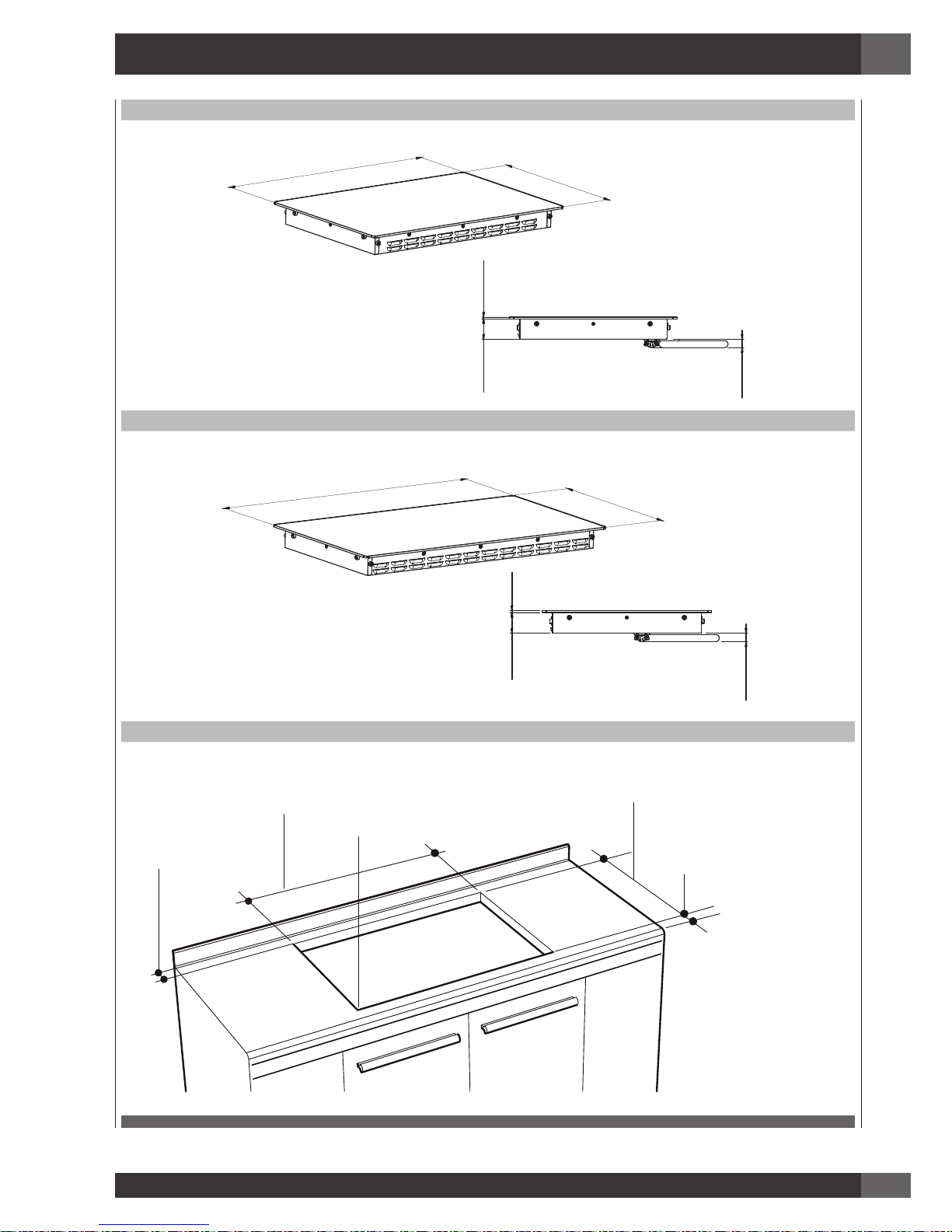
2 - Product Dimensions and Cutout Requirements
30”
30” 3/8
(771 mm)
21” 3/16
(538 mm)
1/4”
(6mm)
2” 5/8
(66 mm)
1” 1/16
(27 mm)
36”
36” 3/16
(919 mm)
21” 3/16
(538 mm)
1/4”
(6mm)
2” 5/8
(66 mm)
1” 1/16
(27 mm)
CUTOUT DIMENSION
LENGTH OF CUT
A
LENGTH OF CUT
B
1-1/2” (3.8CM)
MIN CLEARANCE
SEE NOTE
R
FROM EDGE OF CUTOUT
TO FRONT EDGE OF
COUNTERTOP
2-1/2” (6.5 cm)
EN
4
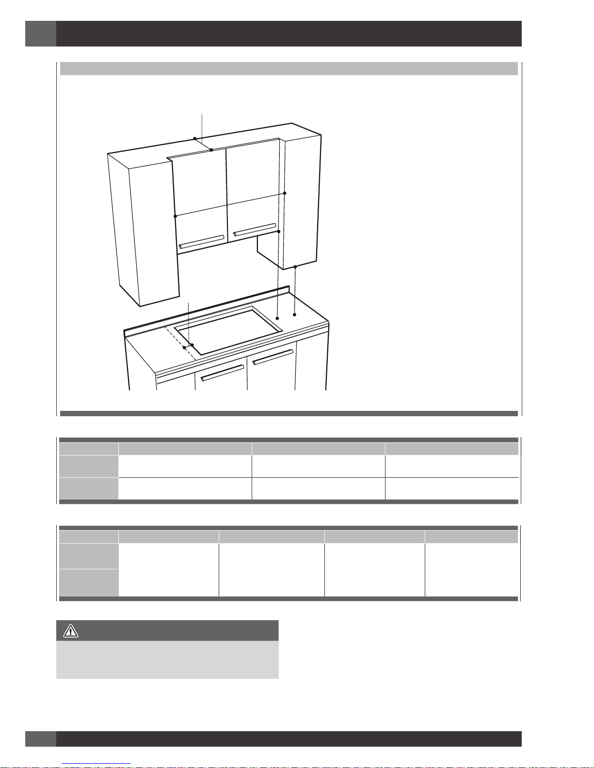
CUTOUT REQUIREMENTS
D
G
C
E
F
WALL COVERING CABINETS,
AND COUNTERTOP MUST
WITHSTAND HEAT UP TO 93° C (200° F)
Cutout width A B C
30”
(76.2cm)
28-3/4” +/- 1/16”
(73.0 cm +/- 0.1cm)
19-7/16” +/- 1/16”
(49.4 cm +/- 1mm)
30”
(76.2 cm) min
36”
(91.4cm)
34-5/8” +/- 1/16”
(87.9 cm +/- 0.1cm)
19-7/16” +/- 1/16”
(49.4 cm +/- 1mm)
36”
(91.4 cm) min
Cutout width D E F G
30”
(76.2cm)
18”
(45.7 cm) min
Height from countertop to
nearest cabinet on either
side of unit
30”
(76.2 cm) min.
(see note*) Clearance from
countertop to unprotected
overhead surface
2”
(5 cm) min
Clearance from cutout to
side wall on the left and
right of the unit
13”
(33 cm)
Depth of unprotected
overhead cabinets
36”
(91.4cm)
IMPORTANT
Under the cooktop it is necessary to install a partition, as
shown
NOTE: 24” (61 cm) min. clearance if bottom of wood or metal
cabinets is protected by not less than 1/4” (0.6 cm) flame
retardant millboard covered with no less than No. 28 MSG
sheet steel 0.015” (0.04 cm) stainless steel, or 0.024”
(0.06 cm) aluminum or 0.020” (0.05 cm) copper. 30”
(76.2 cm) min. clearance between top of cooking platform
and bottom of unprotected wood or metal cabinet.
EN
5
Important Preparation Suggestions
1. Chamfer all exposed edges of decorative laminate to
prevent damage from chipping.
2. Radius corners of cutout and file to ensure smooth edges
and prevent corner cracking. Recommend 1/4” or 3/8”
diameter drill to start cut at each corner.
3. Rough edges, inside corners which have not been rounded
and forced fits can contribute to cracking of the countertop
laminate.
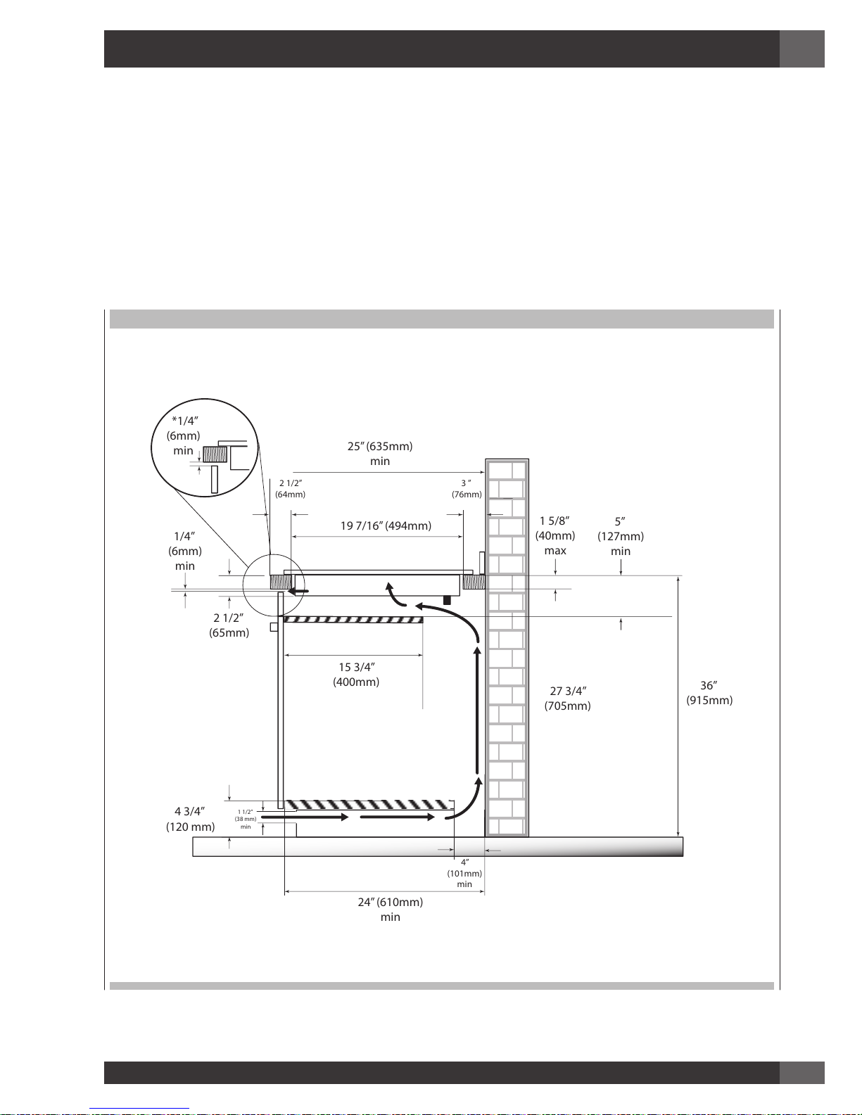
VERTICAL CLEARANCES
* The ventilation opening is to extend the full length of the cooktop cutout.
25” (635mm)
min
19 7/16” (494mm)
2 1/2”
(64mm)
3 ”
(76mm)
2 1/2”
(65mm)
1 5/8”
(40mm)
max
1/4”
(6mm)
min
4”
(101mm)
min
4 3/4”
(120 mm)
36”
(915mm)
27 3/4”
(705mm)
1 1/2”
(38 mm)
min
24” (610mm)
min
15 3/4”
(400mm)
5”
(127mm)
min
*1/4”
(6mm)
min

EN
6
3 - Cooktop Installation
WARNING
Excessive Weight Hazard
Use two or more people to move and install cooktop.
Failure to do so can result in back or other injury.
Cut Hazard
Beware of sharp edges. Use the polystyrene ends when
carrying the product. Failure to use caution could result in
minor injury or cuts.
• Always consult the countertop manufacturer for specific
instructions.
• Ensure the countertop is square and level and ensure no
structural members interfere with space requirements.
• Prepare the cut-out according to the instructions (see cut-out
dimensions).
• Make sure the wall coverings, countertop and cabinets
around the cooktop can withstand heat (up to 200° F /
93°C).
TOOLS WILL YOU NEED
STEP 1
Remove packaging materials and literature package from the
cooktop before beginning installation. Remove Installation
Manual from literature pack and read them carefully before
you begin.
PARTS
COOKTOP
CARDBOARD
TOP-CARDBOARD
MANUAL
GASKET
SCRAPER
TOP PACKAGING
BOTTOM PACKAGING
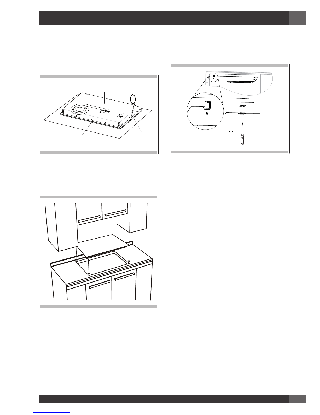
STEP 2
Place a towel or table cloth onto the counter top. Lay the
cooktop upside down onto the protected surface.
COOKTOP HOUSING
TABLE CLOTH
EN
7
STEP 3
A foam tape is provided to seal the cooktop edges to the
countertop. Apply tape approximately 1/16” (1.5 mm) from
the glass edge to the underside of the cooktop glass. Use tape
around the entire glass perimeter. Cut off excess where tape
ends butt.
COOKTOP HOUSING
COOKTOP GLASS
FOAM TAPE SEAL
STEP 4
Insert the cooktop centered into the cutout opening. Make sure
the front edge of the counter top is parallel to the cooktop.
Make a final check that all required clearances are met.
STEP 5
Four or six clamp brackets are provided to clamp the cooktop
to the countertop. Tighten screws just enough to hold brackets in
place when cooktop is put into cutout. Tighten screws securely.
EN
8
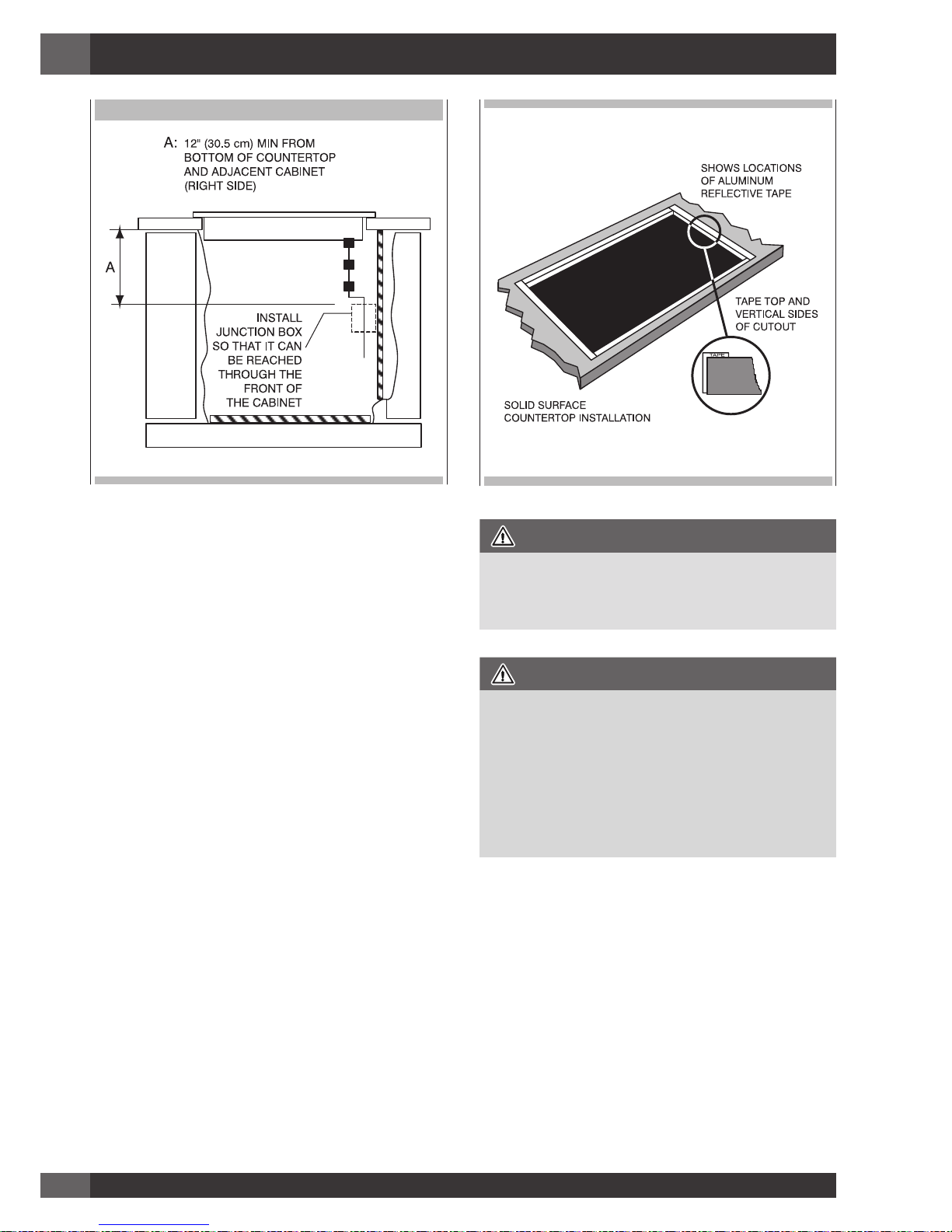
ELECTRIC OPENING
WARNING
THE ELECTRICAL CONDUIT IS 3 FEET LONG
The junction box, must be located where it will allow
considerable slack in the conduit for serviceability.
IMPORTANT
• For solid surface material installations such as Surel™ and
Corian®, consult with solid surface manufacturer. Apply
heat reflective tape such as Scotch® Aluminum Foil Tape
#425 or #427 around the cutout so that it folds over on
the top and sides.
• Do not wrap the tape underneath the cooktop. Be sure the
tape extends beyond the outermost flange of the cooktop.
All corners should be covered with tape.
EN
9
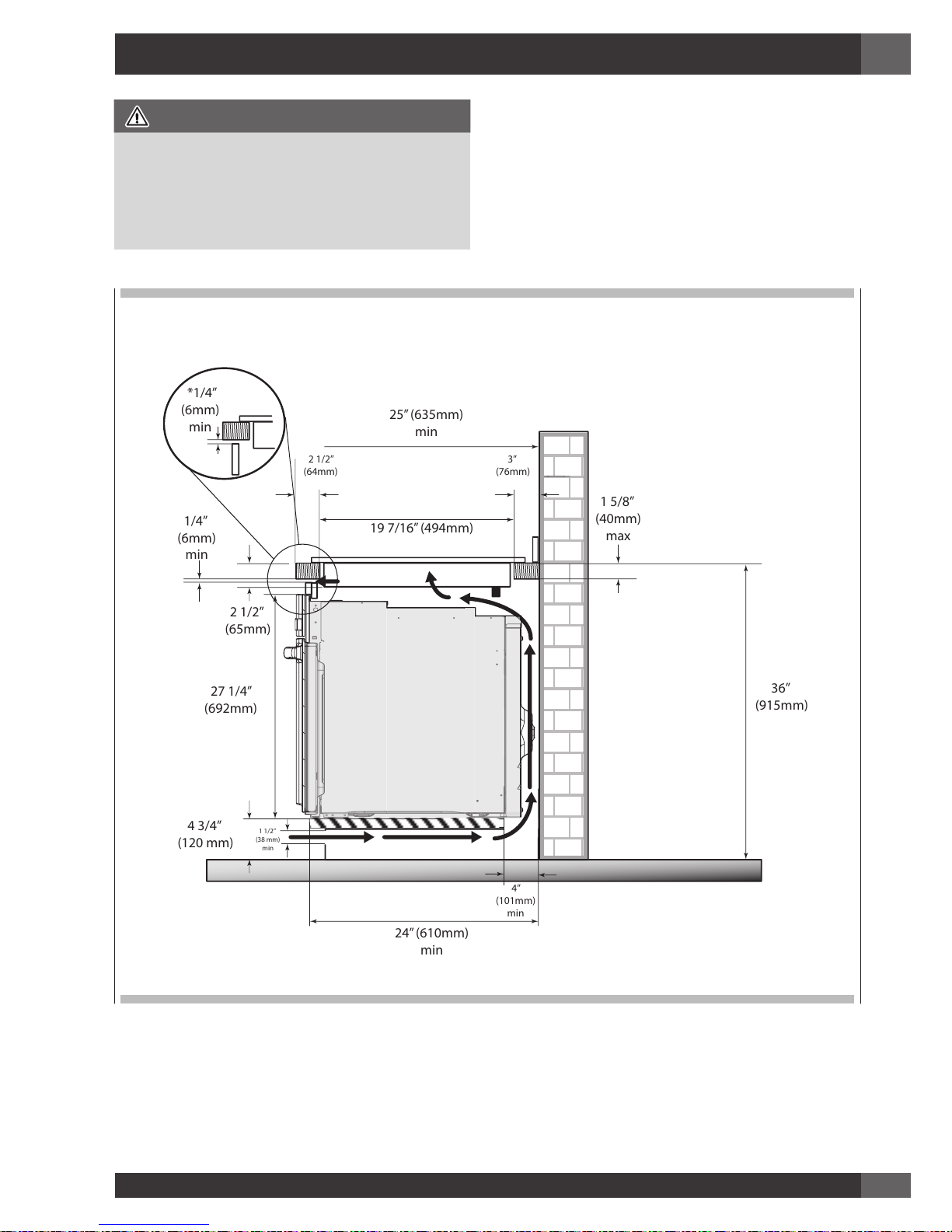
4 - Cooktop Installation Over a Single Oven
CAUTION
• Use the countertop opening dimensions that are given with
these Instructions.
• Check the cooktop base for an approved installation label.
Verify approved oven model numbers that can be installed
with your cooktop model number.
• The cooktop may be installed over a single oven.
• The cooktop should be centred over the oven.
• Both the cooktop and the oven must be installed according
to each specific installation instruction.
* The ventilation opening is to extend the full length of the cooktop cutout.
25” (635mm)
min
19 7/16” (494mm)
3”
(76mm)
2 1/2”
(65mm)
1 5/8”
(40mm)
max
1/4”
(6mm)
min
4”
(101mm)
min
4 3/4”
(120 mm)
36”
(915mm)
27 1/4”
(692mm)
1 1/2”
(38 mm)
min
24” (610mm)
min
*1/4”
(6mm)
min
2 1/2”
(64mm)
EN
10
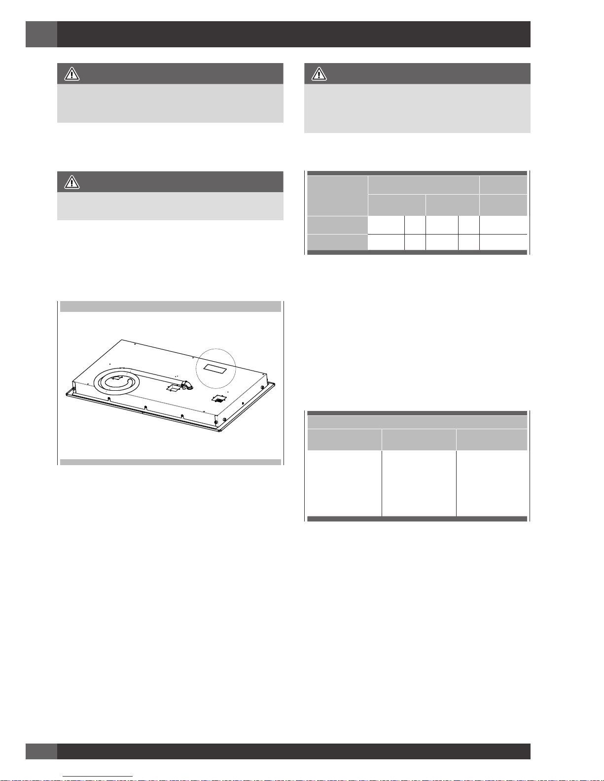
5 - Electrical Connections
DANGER
Disconnect power before servicing the product. Failure to do
so could result in death or electrical shock.
General information
WARNING
The models may be powered at 240V or 208V.
This cooktop does not require a neutral connection. If the cooktop
is to be completely enclosed in a cabinet, feed the cooktop
cable through the opening in the cabinet. Make the electrical
connection following the appropriate steps for your installation.
Your cooktop must be connected to the proper electrical voltage and
frequency as specified in the table on the right.
Location of serial tag
Connect with copper wire only
If the house has aluminum wiring, follow the procedure below:
1. Connect the aluminum wiring to the copper wire by using
special connectors designed and Underwriters Laboratorieslisted for joining copper to aluminum. Follow the electrical
connector manufacturer’s recommended procedure.
2. Aluminum/copper connection must conform with local
codes and industry- accepted wiring practices.
The flexible conduit (supplied) 3 feet long (100 cm)
located at the right rear of the cooktop bottom box should
be connected directly into a junction box. Do not cut the
conduit. A U.L - or CSA - listed conduit connector must
be provided at each end of the power supply cable (at
the cooktop and at the junction box.) A time delay fuse or
circuit breaker is recommended. Do not ground to a gas
pipe. Do not have a fuse in the grounding or neutral circuit.
Fuse both supply (phase) lines.
WARNING
Improper connection of aluminum house wiring to the copper
leads can result in a serious problem such as an electrical
fire.
Model Power Supply
240 V 60 Hz 208 V 60 Hz
Approval
code
30” F7IT30*1
7,2kW 30A 6,45 31A 815T40*T
36” F7IT36*1
10,8kW 45A 9,4kW 45A 815V50*U
National Fire Protection Association Batterymarch
Park, Quincy, Massachusetts 02169-7471
A three-wire, single phase, 240 Volt 60 cycle electrical system
(properly circuit protected to meet Local Codes of NFPA
No.70) must be provided. Unit must be properly grounded
in accordance with local wiring code. The chart below
recommends the minimum circuit protector and wire size if the
appliance is the only unit on the circuit. If smaller sizes of wire
are used, the unit efficiency will be reduced and a fire hazard
may be created. It is advisable that the electrical wiring and
hookup be accomplished by a competent electrician.
Recommended Minimum
kW Rating on
serial plate
Circuit protection in
amperes
Wire size (AWG)
0-4.8 20 12
4.9-6.9 30 10
7.0-9.9 40 8
10.0-11.9 50 8
12.0-14.9 60 6
Be sure your appliance is properly installed and grounded by a
qualified technician. Ask your dealer to recommend a qualified
technician or an authorized repair service. This cooktop does not
require a neutral connection. If the cooktop is to be completely
enclosed in a cabinet, feed the cooktop cable through the
opening in the cabinet. Make the electrical connection following
the appropriate steps for your installation.
 Loading...