

Page 1
INDUCTION
COOKTOP
SERIES 700
INSTALLATION INSTRUCTIONS
INSTRUCTIONS D’INSTALLATION
INSTRUCCIONES PARA LA INSTALACIÓN
Page 2

Page 3

Dear Customer,
Thank you for purchasing a Fulgor Milano product. Fulgor Milano is
committed to excellence and our signature technologies provide you with
professional tools for your kitchen. One of our central philosophies is
continuous investment in research that is rooted in developing life enhancing
technology. Our goal is to deliver products that are worthy of your family
recipes and that will breathe life into your kitchen, the heart of your home.
We invite you to enjoy your new Fulgor Milano product with same amount
of care and attention that we have put into creating it.
Your Life | Our Passion
Page 4

Page 5

Pay attention to these symbols present in this manual:
EN
TABLE OF CONTENTS PAG E
1 - Special Warnings 2
Before Starting Installation 2
2 - Product Dimensions and Cutout Requirements 3
Important Preparation Suggestions 5
3 - Cooktop Installation 6
4 - Cooktop Installation Over a Single Oven 9
5 - Electrical Connections 10
General information 10
3-Wire branch circuit 11
4--Wire branch circuit 11
IMPORTANT: Save these instructions for the local electrical
inspector use.
INSTALLER: Please leave this manual with owner for future
reference.
OWNER: Please keep this manual for future reference.
DANGER
You can be killed or seriously injured if you don’t
IMMEDIATELY follow instructions.
WARNING
This is the safety alert symbol. This symbol alerts you to
potential hazards that can kill or hurt you and others.
You can be killed or seriously injured if you don’t follow these
instructions.
WARNING
If the information in this manual is not followed
exactly, a fire or explosion may result in personal injur y or death.
Do not store or use gasoline or other flammable vapors and
liquids in the vicinity of this or any other appliance.
1
Page 6
EN
1 - Special Warnings
IMPORTANT INSTRUCTION
Please read all instruction before using this appliance.
Proper installation is your responsibility.
Have a qualified technician install this cooktop.
IMPORTANT
- Observe all governing codes and ordinances.
- Write down the model and serial numbers before installing
the cook top. Both numbers are on the serial rating plate
located on bottom of cooktop housing.
Before Starting Installation
WARNING
It is the customer’s responsibility to contact a qualified
electrical installer to ensure that the electrical installation is
adequate and in conformity with national electrical code:
ANSI/NFPA 70-latest edition** or CSA standards C22.194, Canadian Electrical Code, part No.0-M91 - latest
edition*** and all local codes and ordinances.
Copies of the standards listed may be obtained from:
** National Fire Protection Association One Batterymarch Park
Quincy, Massachusetts 02269
*** CSA International 8501 East Pleasant Valley Rd. Cleveland,
OH 44131-5575
To eliminate the risk of burns by reaching over heated surface
units, cabinet storage space located above the surface units
should be avoided. If cabinet storage is to be provided, the
risk can be reduced by installing a range hood that projects
horizontally a minimum of 5” (12,7 cm) beyond the outer edge
of the cabinet.
2
Page 7
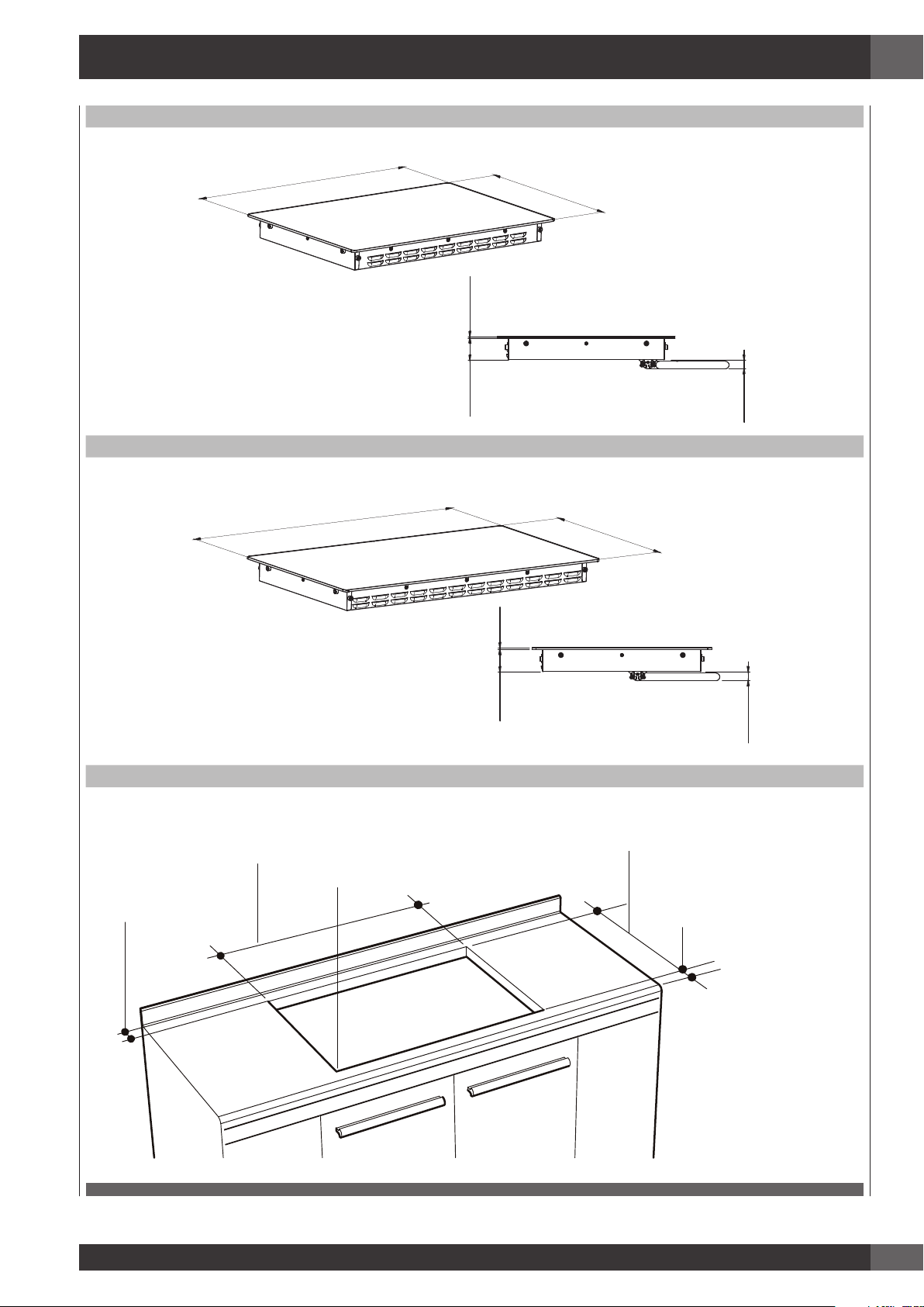
2 - Product Dimensions and Cutout Requirements
30”
EN
30” 3/8
(771 mm)
36” 3/16
(919 mm)
1/4”
(6mm)
2” 5/8
(66 mm)
36”
21” 3/16
(538 mm)
1” 1/16
(27 mm)
21” 3/16
(538 mm)
LENGTH OF CUT
1-1/2” (3.8CM)
MIN CLEARANCE
1/4”
(6mm)
2” 5/8
(66 mm)
1” 1/16
(27 mm)
CUTOUT DIMENSION
LENGTH OF CUT
B
A
SEE NOTE
R
FROM EDGE OF CUTOUT
TO FRONT EDGE OF
COUNTERTOP
2-1/2” (6.5 cm)
3
Page 8
EN
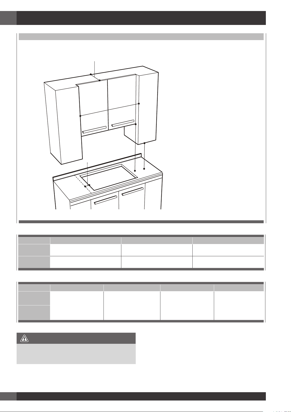
CUTOUT REQUIREMENTS
G
WALL COVERING CABINETS,
AND COUNTERTOP MUST
WITHSTAND HEAT UP TO 93° C (200° F)
C
E
F
D
Cutout width A B C
30”
(76.2cm)
36”
(91.4cm)
28-3/4” +/- 1/16”
(73.0 cm +/- 0.1cm)
34-5/8” +/- 1/16”
(87.9 cm +/- 0.1cm)
19-7/16” +/- 1/16”
(49.4 cm +/- 1mm)
19-7/16” +/- 1/16”
(49.4 cm +/- 1mm)
30”
(76.2 cm) min
36”
(91.4 cm) min
Cutout width D E F G
30”
(76.2cm)
36”
(91.4cm)
Height from countertop to
nearest cabinet on either
IMPORTANT
Under the cooktop it is necessary to install a partition, as
shown
18”
(45.7 cm) min
side of unit
30”
(76.2 cm) min.
(see note*) Clearance from
countertop to unprotected
overhead surface
NOTE: 24” (61 cm) min. clearance if bottom of wood or metal
2”
(5 cm) min
Clearance from cutout to
side wall on the left and
(33 cm)
Depth of unprotected
overhead cabinets
right of the unit
cabinets is protected by not less than 1/4” (0.6 cm) flame
retardant millboard covered with no less than No. 28 MSG
sheet steel 0.015” (0.04 cm) stainless steel, or 0.024”
(0.06 cm) aluminum or 0.020” (0.05 cm) copper. 30”
(76.2 cm) min. clearance between top of cooking platform
and bottom of unprotected wood or metal cabinet.
13”
4
Page 9
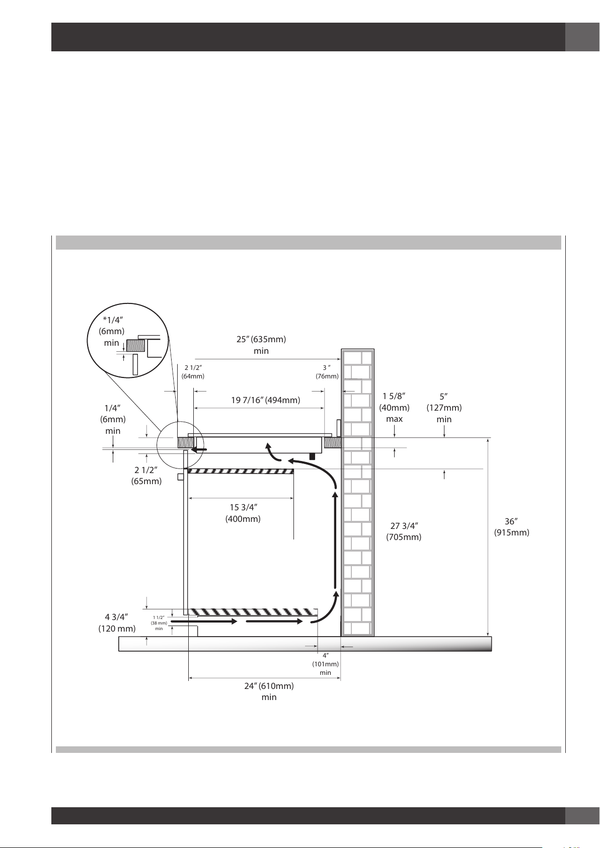
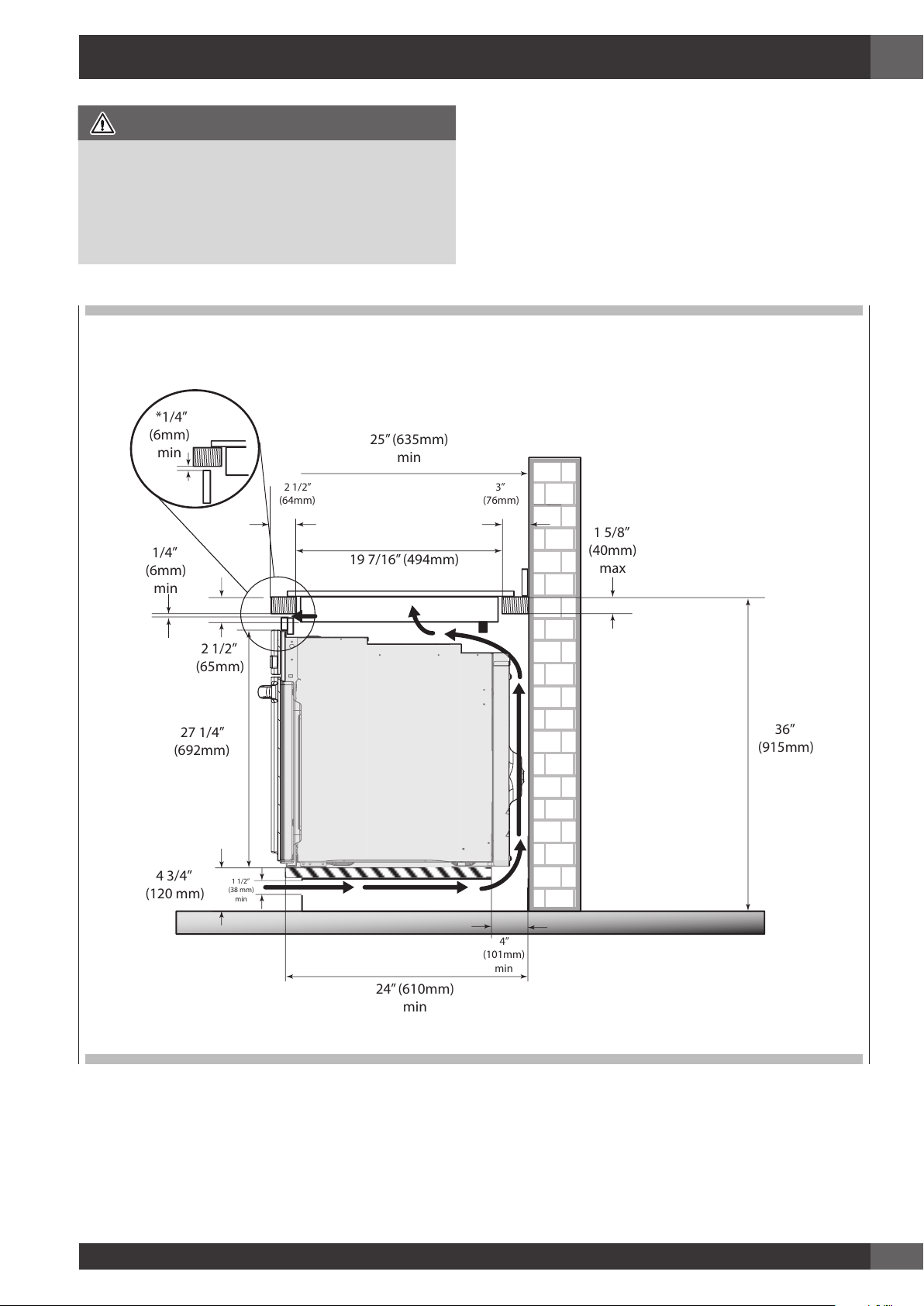
Important Preparation Suggestions
25” (635mm)
min
19 7/16” (494mm)
2 1/2”
(64mm)
3 ”
(76mm)
2 1/2”
(65mm)
1 5/8”
(40mm)
max
1/4”
(6mm)
min
4”
(101mm)
min
4 3/4”
(120 mm)
36”
(915mm)
27 3/4”
(705mm)
1 1/2”
(38 mm)
min
24” (610mm)
min
15 3/4”
(400mm)
5”
(127mm)
min
*1/4”
(6mm)
min
1. Chamfer all exposed edges of decorative laminate to
prevent damage from chipping.
2. Radius corners of cutout and file to ensure smooth edges
and prevent corner cracking. Recommend 1/4” or 3/8”
diameter drill to start cut at each corner.
3. Rough edges, inside corners which have not been rounded
and forced fits can contribute to cracking of the countertop
laminate.
VERTICAL CLEARANCES
* The ventilation opening is to extend the full length of the cooktop cutout.
EN
5
Page 10
EN
3 - Cooktop Installation
WARNING
Excessive Weight Hazard
Use two or more people to move and install cooktop.
Failure to do so can result in back or other injury.
Cut Hazard
Beware of sharp edges. Use the polystyrene ends when
carrying the product. Failure to use caution could result in
minor injury or cuts.
• Always consult the countertop manufacturer for specific
instructions.
• Ensure the countertop is square and level and ensure no
structural members interfere with space requirements.
• Prepare the cut-out according to the instructions (see cut-out
dimensions).
• Make sure the wall coverings, countertop and cabinets
around the cooktop can withstand heat (up to 200° F /
93°C).
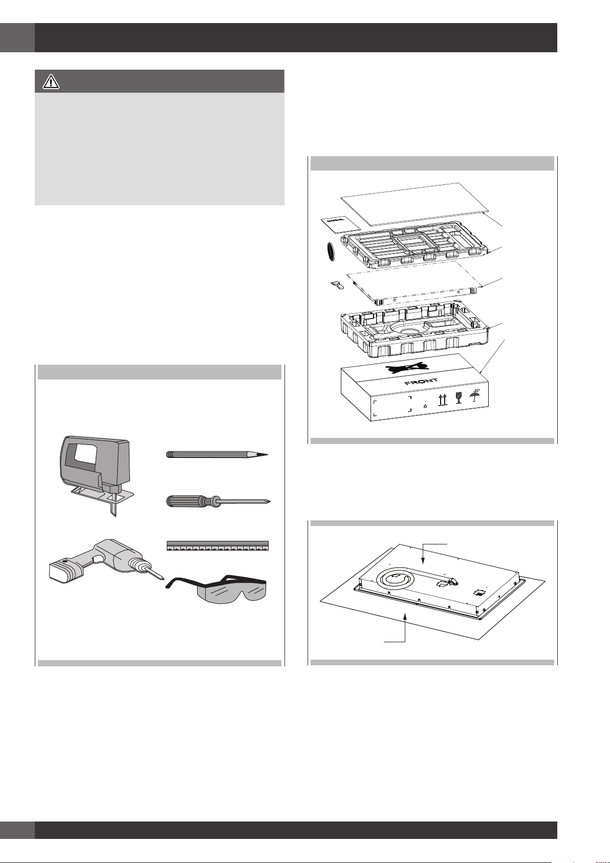
STEP 1
Remove packaging materials and literature package from the
cooktop before beginning installation. Remove Installation
Manual from literature pack and read them carefully before
you begin.
PARTS
MANUAL
TOP-CARDBOARD
TOP PACKAGING
GASKET
COOKTOP
SCRAPER
BOTTOM PACKAGING
CARDBOARD
TOOLS WILL YOU NEED
STEP 2
Place a towel or table cloth onto the counter top. Lay the
cooktop upside down onto the protected surface.
COOKTOP HOUSING
TABLE CLOTH
6
Page 11
EN
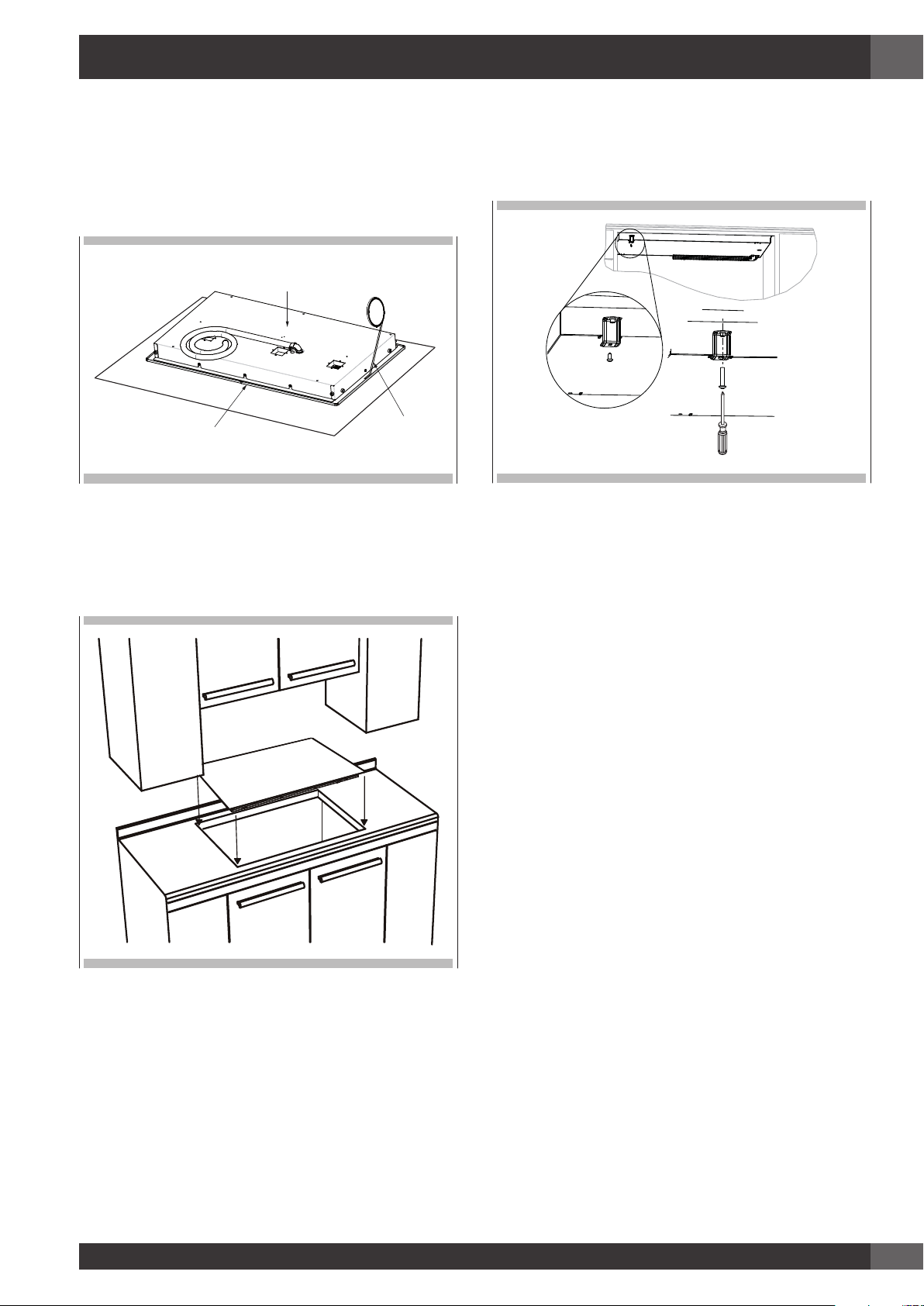
STEP 3
A foam tape is provided to seal the cooktop edges to the
countertop. Apply tape approximately 1/16” (1.5 mm) from
the glass edge to the underside of the cooktop glass. Use tape
around the entire glass perimeter. Cut off excess where tape
ends butt.
COOKTOP HOUSING
COOKTOP GLASS
FOAM TAPE SEAL
STEP 4
Insert the cooktop centered into the cutout opening. Make sure
the front edge of the counter top is parallel to the cooktop.
Make a final check that all required clearances are met.
STEP 5
Four or six clamp brackets are provided to clamp the cooktop
to the countertop. Tighten screws just enough to hold brackets in
place when cooktop is put into cutout. Tighten screws securely.
7
Page 12
EN
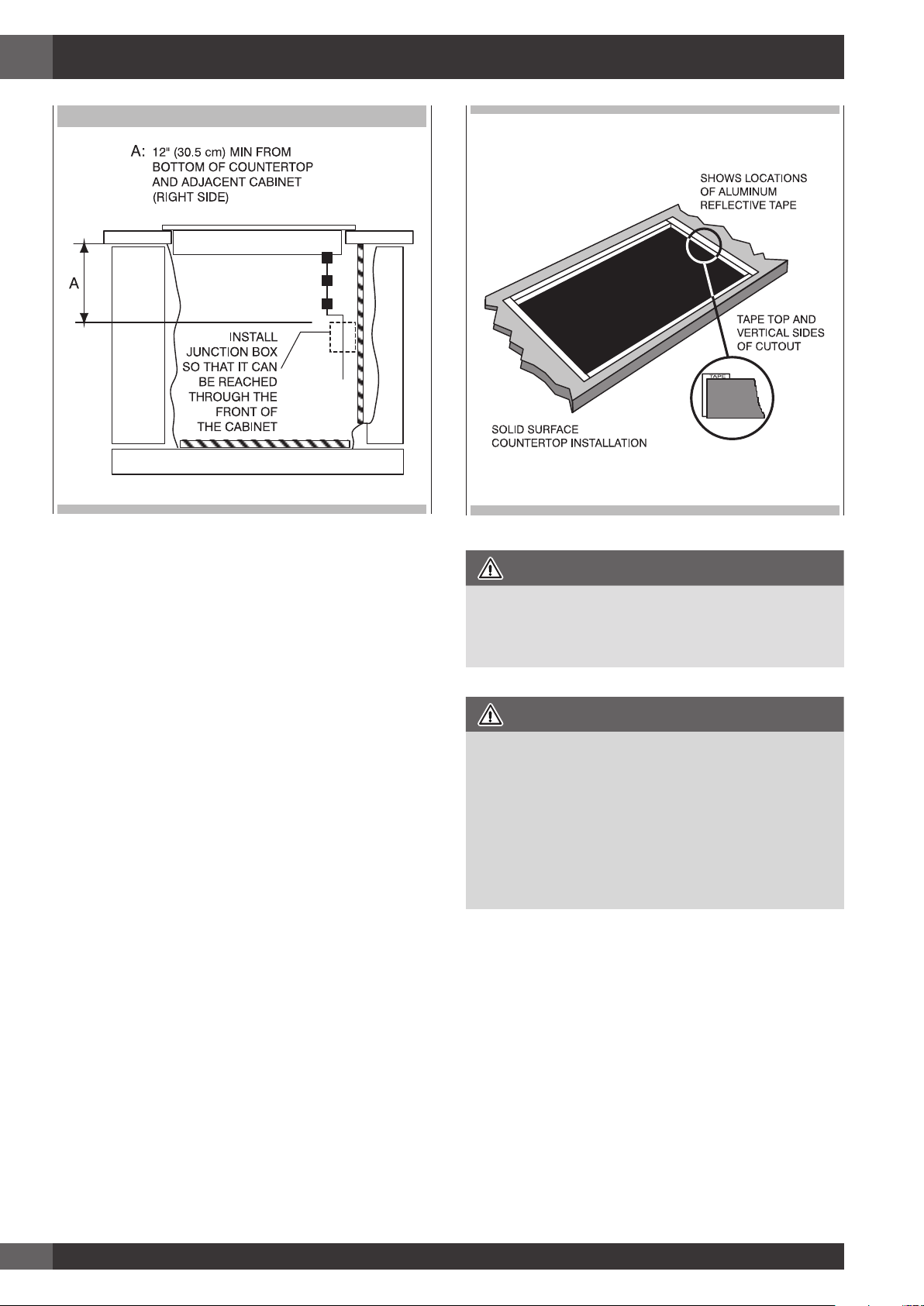
ELECTRIC OPENING
WARNING
THE ELECTRICAL CONDUIT IS 3 FEET LONG
The junction box, must be located where it will allow
considerable slack in the conduit for serviceability.
IMPORTANT
• For solid surface material installations such as Surel™ and
Corian®, consult with solid surface manufacturer. Apply
heat reflective tape such as Scotch® Aluminum Foil Tape
#425 or #427 around the cutout so that it folds over on
the top and sides.
• Do not wrap the tape underneath the cooktop. Be sure the
tape extends beyond the outermost flange of the cooktop.
All corners should be covered with tape.
8
Page 13
CAUTION
25” (635mm)
min
19 7/16” (494mm)
3”
(76mm)
2 1/2”
(65mm)
1 5/8”
(40mm)
max
1/4”
(6mm)
min
4”
(101mm)
min
4 3/4”
(120 mm)
36”
(915mm)
27 1/4”
(692mm)
1 1/2”
(38 mm)
min
24” (610mm)
min
*1/4”
(6mm)
min
2 1/2”
(64mm)
4 - Cooktop Installation Over a Single Oven
EN
• Use the countertop opening dimensions that are given with
• The cooktop may be installed over a single oven.
these Instructions.
• Check the cooktop base for an approved installation label.
Verify approved oven model numbers that can be installed
• The cooktop should be centred over the oven.
• Both the cooktop and the oven must be installed according
with your cooktop model number.
* The ventilation opening is to extend the full length of the cooktop cutout.
to each specific installation instruction.
9
Page 14
EN
5 - Electrical Connections
DANGER
Disconnect power before servicing the product. Failure to do
so could result in death or electrical shock.
General information
WARNING
The models may be powered at 240V or 208V.
This cooktop does not require a neutral connection. If the cooktop
is to be completely enclosed in a cabinet, feed the cooktop
cable through the opening in the cabinet. Make the electrical
connection following the appropriate steps for your installation.
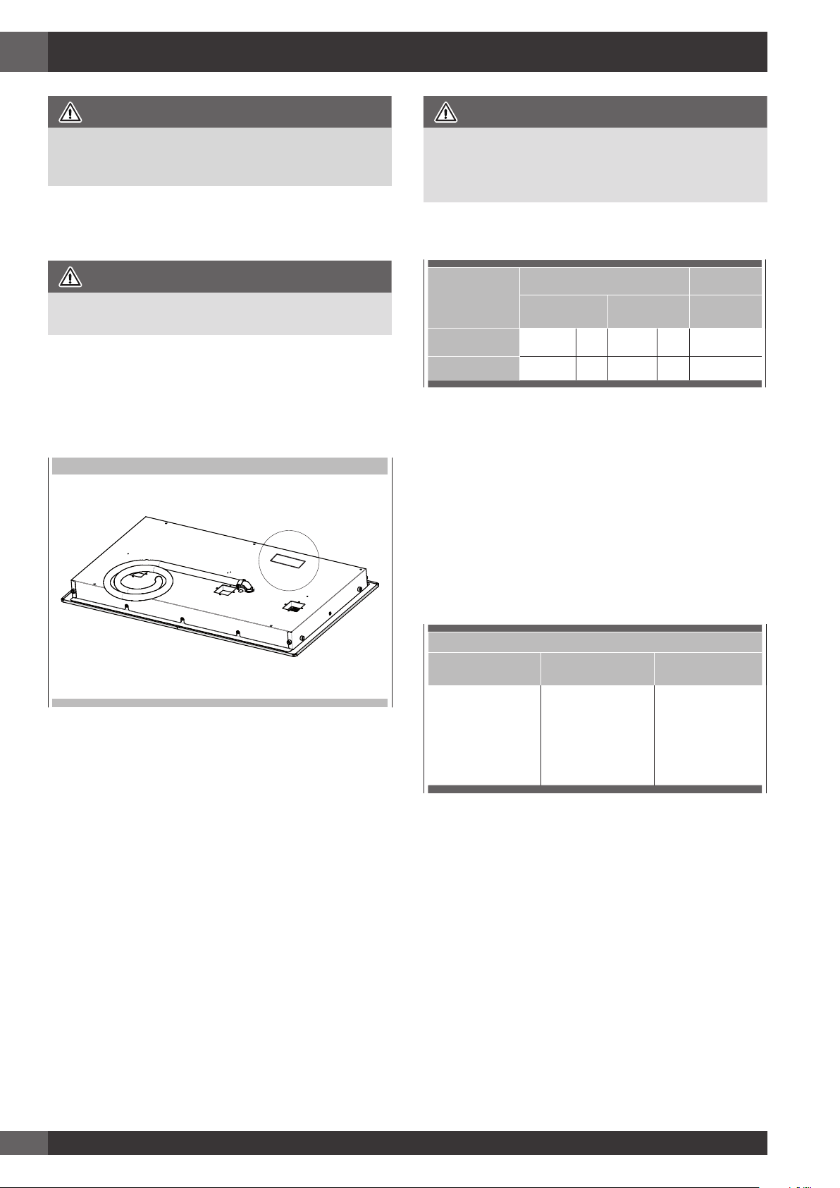
Your cooktop must be connected to the proper electrical voltage and
frequency as specified in the table on the right.
Location of serial tag
WARNING
Improper connection of aluminum house wiring to the copper
leads can result in a serious problem such as an electrical
fire.
Model Power Supply
240 V 60 Hz 208 V 60 Hz
30” F7IT30*1
36” F7IT36*1
7,2kW 30A 6,45 31A 815T40*T
10,8kW 45A 9,4kW 45A 815V50*U
National Fire Protection Association Batterymarch
Park, Quincy, Massachusetts 02169-7471
A three-wire, single phase, 240 Volt 60 cycle electrical system
(properly circuit protected to meet Local Codes of NFPA
No.70) must be provided. Unit must be properly grounded
in accordance with local wiring code. The chart below
recommends the minimum circuit protector and wire size if the
appliance is the only unit on the circuit. If smaller sizes of wire
are used, the unit efficiency will be reduced and a fire hazard
may be created. It is advisable that the electrical wiring and
hookup be accomplished by a competent electrician.
Approval
code
Connect with copper wire only
If the house has aluminum wiring, follow the procedure below:
1. Connect the aluminum wiring to the copper wire by using
special connectors designed and Underwriters Laboratorieslisted for joining copper to aluminum. Follow the electrical
connector manufacturer’s recommended procedure.
2. Aluminum/copper connection must conform with local
codes and industry- accepted wiring practices.
The flexible conduit (supplied) 3 feet long (100 cm)
located at the right rear of the cooktop bottom box should
be connected directly into a junction box. Do not cut the
conduit. A U.L - or CSA - listed conduit connector must
be provided at each end of the power supply cable (at
the cooktop and at the junction box.) A time delay fuse or
circuit breaker is recommended. Do not ground to a gas
pipe. Do not have a fuse in the grounding or neutral circuit.
Fuse both supply (phase) lines.
Recommended Minimum
kW Rating on
serial plate
0-4.8 20 12
4.9-6.9 30 10
7.0-9.9 40 8
10.0-11.9 50 8
12.0-14.9 60 6
Be sure your appliance is properly installed and grounded by a
qualified technician. Ask your dealer to recommend a qualified
technician or an authorized repair service. This cooktop does not
require a neutral connection. If the cooktop is to be completely
enclosed in a cabinet, feed the cooktop cable through the
opening in the cabinet. Make the electrical connection following
the appropriate steps for your installation.
Circuit protection in
amperes
Wire size (AWG)
10
Page 15

This appliance is manufactured with a green ground wire connected to the cooktop chassis. After making sure that the power
has been turned off, connect the flexible conduit from the cooktop to the junction box using a U.L. listed conduit connector. The
instructions provided below present the most common way of connecting the cooktops. Your local codes and ordinances, of course,
take precedence over these instructions. Complete electrical connections according to local codes and ordinances.
DANGER
Risk of Electric Shock, frame grounded to neutral of appliance through a link.
Grounding through the neutral conductor is prohibited for new branch-circuit installations (1996 NEC); mobile homes; and
recreational vehicles, or in an area where local codes prohibit grounding through the neutral conductor.
EN
3-Wire branch circuit
Where local codes allow the connection of ground wire from
the cooktop to the branch circuit neutral wire (gray or white
colored wire) proceed as follows.
1. If local codes permit, connect the green GROUND wire
from the cooktop to the branch circuit neutral wire (gray or
white colored wire).
2. Connect the red and black leads from the cooktop to the
corresponding leads in the junction box.
Cable from power supply
Red Wires
Junction box
Twist-on connector
4--Wire branch circuit
1. Connect the green ground wire from the cooktop to the
ground wire in the junction box (bare or green colored
wire).
2. Connect the red and black leads from the cooktop to the
corresponding leads in the junction box.
3. Terminate and insulate the neutral (gray or white colored
wire) in the junction box.
Cable from power supply
Red wires
Junction box
White wire
White Wires
Bare or green wires
3-Wire cable from cooktop
U.L.-or CSA-listed conduit connector
Where local codes permit connecting the frame-ground
conductor to the neutral (white) junction box wire.
(Not used for Canadian installations)
Black wires
Bare or green wires
3-Wire cable from cooktop
U.L. - or CSA-listed conduit connector
Twist-on
connector
Black wires
11
Page 16

Notes
12
Page 17

Veuillez prêter attention à ces symboles que vous rencontrerez
dans ce manuel
FR
TABLES DES MATIERES PAG E
1 - Avertissement Spéciaux 2
Avant de Procéder à l’Installation 2
2 - Dimensions du Produit et Découpe 3
Conseils importants de préparation 5
3 - Installation de la Table de Cuisson 6
4 - Installation de la Plaque de Cuisson
sur un Four Simple 9
5 - Connexions Electriques 10
Informations générales 10
Connexion à 3 fils 11
Connexion à 4 fils 11
IMPORTANT: Gardez ces instructions pour une utilization
d’inspection électrique locale
INSTALLATEUR: Veuillez laisser ce manuel au propriétaire
pour de futures références.
PROPRIETAIRE: Veuillez garder ce manuel pour de futures
références.
DANGER
Si vous ne suivez pas IMMEDIATEMENT ces instructions,
vous courez le risque de mourir ou d’être sérieusement
blessé.
AVERTISSEMENT
• Ce symbole signifie que la sécurité est en danger. Il signale
les risques potentiels qui peuvent entraîner la mort ou des
blessures à l’opérateur ou aux autres.
• Si vous ne suivez pas ces instructions à la lettre, vous
courez le risque de mourir ou d’être sérieusement blessé.
AVERTISSEMENT
• La non-observation des instructions contenues dans ce
manuel peut entraîner la mort ou des blessures sérieuses
du fait d’un incendie ou d’une explosion.
• Ne pas stocker ou utiliser de l’essence ou d’autres liquides
inflammables à proximité de cet appareil ou de tout autre
appareil électroménager.
1
Page 18

FR
1 - Avertissement Spéciaux
AVERTISSEMENT
Veuillez lire les instructions avant toute utilisation
Il est de votre responsabilité d’installer l’appareil correctement.
Confiez l’installation de cette table de cuisson à un technicien
qualifié.
IMPORTANT
• Respecter les règlements et ordonnances en vigueur.
• Avant d’installer la table de cuisson, veuillez noter les
numéros de modèle et de série. Ces deux numéros se
trouvent sur la plaquette signalétique située en dessous de
la caisse de la table de cuisson.
Avant de Procéder à l’Installation
AVERTISSEMENT
La responsabilité revient au client de contacter un électricien
installateur qualifié. Veuillez vous assurer que l’installation
électrique est adéquate et conforme à la réglementation
électrique nationale : ANSI/NFPA 70 -dernière édition
** ou normes CSA C22.1-94, réglementation électrique
canadienne, partie No.0-M91 – dernière édition *** et
tous les règlements et ordonnances locaux.
Copies des normes mentionnées ci-dessus peuvent être obtenues:
** National Fire Protection Association One Batterymarch Park
Quincy, Massachusetts 02269
*** CSA International 8501 East Pleasant Valley Rd. Cleveland,
OH 44131-5575
Pour éviter le risque de brûlures en touchant les surfaces
chauffées, l’espace de stockage du meuble au
dessus des unités de surface doit être évité. Si le
meuble de stockage est fourni, le risque peut être réduit
en installant une hotte qui projète horizontalement
un minimum de 5” (12,7 cm) sous le dessous
du meuble.
2
Page 19

2 - Dimensions du Produit et Découpe
30”
FR
30” 3/8
(771 mm)
36” 3/16
(919 mm)
1/4”
(6mm)
2” 5/8
(66 mm)
36”
21” 3/16
(538 mm)
1” 1/16
(27 mm)
21” 3/16
(538 mm)
LONGUEUR DE DÉCOUPE
1-1/2” (3.8CM)
ESPACE MINIMUM
A
VOIR NOTE
R
1/4”
(6mm)
2” 5/8
(66 mm)
DIMENSION DE LA DÉCOUPE
LONGUEUR DE DÉCOUPE
1” 1/16
(27 mm)
B
DU BORD DE LA DÉCOUPE
AU BORD ANTÉRIEUR DU
PLAN DE TRAVAIL
2-1/2” (6.5 cm)
3
Page 20

FR
DISPOSITIONS POUR LA DÉCOUPE
G
LES REVETEMENTS DES MEUBLES ET LE
PLAN DE TRAVAIL DOIVENT RESISTER A
UNE CHALEUR DE 93° C (200° F)
C
E
F
D
Découpe largeur A B C
30”
(76.2cm)
36”
(91.4cm)
28-3/4” +/- 1/16”
(73.0 cm +/- 0.1cm)
34-5/8” +/- 1/16”
(87.9 cm +/- 0.1cm)
19-7/16” +/- 1/16”
(49.4 cm +/- 1mm)
19-7/16” +/- 1/16”
(49.4 cm +/- 1mm)
30”
(76.2 cm) min
36”
(91.4 cm) min
Découpe largeur D E F G
30”
(76.2cm)
36”
(91.4cm)
Hauteur min. du plan de
travail au meuble le plus
près des deux cotés de
IMPORTANT
En dessous de la table de cuisson, il est nécessaire d’installer
une cloison.
18”
(45.7 cm) min
l’appareil
30”
(76.2 cm) min.
(voir note*) Du plan de
travail à la surface non
protégée à la verticale
NOTE: 24” (61 cm) espace min. si le bas des meubles en bois
30” (76,2 cm) d’espace min. entre le haut de la plate-
2”
(5 cm) min
Espace min. de la
découpe à la paroi
latérale sur la gauche et
Profondeur des meubles
(33 cm)
non protégées à la
verticale
la droite de l’appareil
ou en métal est protégée par au moins 1/4“ (0,6 cm) de
carton-reliure ignifuge avec une tôle d’acier inoxydable No.
28 MSG d’au moins 0.015” (0,04 cm), ou d’aluminium
0.024” (0,06 cm) ou de cuivre 0.020” (0,05cm).
forme de cuisson et le bas du meuble non-protégé en bois
ou métal.
13”
4
Page 21

Conseils importants de préparation
25” (635mm)
min
19 7/16” (494mm)
2 1/2”
(64mm)
3 ”
(76mm)
2 1/2”
(65mm)
1 5/8”
(40mm)
max
1/4”
(6mm)
min
4”
(101mm)
min
4 3/4”
(120 mm)
36”
(915mm)
27 3/4”
(705mm)
1 1/2”
(38 mm)
min
24” (610mm)
min
15 3/4”
(400mm)
5”
(127mm)
min
*1/4”
(6mm)
min
1. Biseautez tous les bords exposés du contre-plaqué décoratif
pour empêcher qu’ils ne s’écaillent.
2. Arrondissez les quatre coins de la découpe et limez le
pourtour pour que les bords soient lisses et que les coins ne
se fissurent pas. Utilisez une mèche de 1/4‘’ ou 3/8’’ pour
percer les trous à chaque angle.
3. Si les bords ne sont pas lisses, l’intérieur des coins n’est pas
arrondi et l’encastrement a été forcé, il est possible que le
contre-plaqué du plan de travail se fendille.
DEGAGEMENTS DU SOL
* L’ouverture d’aération doit être équivalente à la longueur de l’ouverture d’installation de la table de cuisson.
FR
5
Page 22

FR
3 - Installation de la Table de Cuisson
AVERTISSEMENT
Risque du fait du poids excessif
Soyez à deux personnes ou plus pour porter et installer la
table de cuisson. Sinon, vous risquez de vous blesser au dos
ou de subir d’autres blessures.
Risque de coupure
Méfiez-vous des bords tranchants et des extrémités du
polystyrène lorsque vous portez le produit.
Sinon, vous risquez de vous couper ou de vous faire
légèrement mal.
• Toujours consulter le fabricant du plan de travail pour les
instructions spécifiques.
• Bien vérifier que le plan de travail est carré et à niveau et
assurez-vous qu’aucun élément de structure n’interfère avec
les exigences d’espace.
• Préparez la découpe selon les instructions (voir dimensions
découpe).
• Bien vérifier que les éléments suspendus, le plan de travail
et les meubles autour de la table de cuisson résistent à la
chaleur (jusqu’à 200 °F / 93 °C).
ÉTAPE 1
Enlevez les matériaux d’emballage et les manuels d’explication
de la table de cuisson avant de commencer l’installation.
Retirez les Instructions d’installation du manuel et lisez-les
soigneusement avant de commencer.
PIÉCES
MANUEL
PANNEAU CARTON
SUPÉRIEUR
EMBALLAGE DU HAUT
JOINT
RACLOIR À
LAME DE RASOIR
TABLE DE CUISSON
EMBALLAGE DU BAS
CARTON
LES OUTILS DONT VOUS AUREZ BESOIN
ÉTAPE 2
Placez un torchon ou une serviette sur le plan de travail.
Posez la table de cuisson du haut vers le bas dans la surface
protégée.
CAISSON DES FOYERS
SERVIETTE
6
Page 23

FR
ÉTAPE 3
Un ruban adhésif est fourni pour assurer l’étanchéité entre les
bords de la table de cuisson et les angles du plan de travail.
Appliquez le ruban à environ 1/16”(1,5 mm) des angles en
verre au dos du verre de la table de cuisson. Utilisez un ruban
tout autour du périmètre du verre. Coupez le ruban en trop.
CAISSON DES FOYERS
RUBAN ADHÈSIF
VERRE DE LA TABLE DE CUISSON
ÈTANCHE
ÉTAPE 5
Quatre ou six supports de fixation sont fournis pour accrocher
la table de cuisson au plan de travail. Serrez les vis juste assez
pour tenir en place les fixations lorsque la table de cuisson est
mise dans la découpe. Serrez bien les vis.
ÉTAPE 4
Insérez la table de cuisson centre de l’ouverture de la découpe.
Vérifiez que le bord avant du plan de travail est parallèle à la
table de cuisson. Faites la dernière vérification que vous avez
laissé tous les espaces nécessaires.
7
Page 24

FR
OUVERTURE DES LIGNES ÉLECTRIQUES
AVERTISSEMENT
LE CONDUIT A UNE LONGUEUR DE 3 PIEDS
la boîte de jonction, doit être dans un endroit qui permette
que le conduit pour l’entretien ait suffisamment de jeu.
IMPORTANT
• Pour les installations de matériau solide comme le
Surei™ et le Corian®, consultez le fabricant de surface
solide. Appliquez du ruban thermoréfléchissant comme
le Scotch® feuille de ruban aluminium #425 ou #427
autour de la découpe de sorte qu’il déborde et se replie
sur le dessus et les côtés.
• N’enveloppez pas le ruban en-dessous de la table de
cuisson. Vérifiez bien que le ruban aille audelà du rebord
le plus externe de la table de cuisson. Tous les angles
doivent être recouverts par du ruban.
8
Page 25

ATTENTION
25” (635mm)
min
19 7/16” (494mm)
3”
(76mm)
2 1/2”
(65mm)
1 5/8”
(40mm)
max
1/4”
(6mm)
min
4”
(101mm)
min
4 3/4”
(120 mm)
36”
(915mm)
27 1/4”
(692mm)
1 1/2”
(38 mm)
min
24” (610mm)
min
*1/4”
(6mm)
min
2 1/2”
(64mm)
4 - Installation de la Plaque de Cuisson sur un Four Simple
FR
• • Utiliser les dimensions d’ouverture du comptoir qui sont
données avec ces instructions.
• Ces tables de cuisson peuvent être installées sur un four
simple.
• • Vérifier la base de la table de cuisson pour un label
d’installation approuvé. Vérifier le numéro de référence
du modèle de four approuvé qui peut être installé avec le
numéro de référence de la table de cuisson.
* L’ouverture d’aération doit être équivalente à la longueur de l’ouverture d’installation de la table de cuisson.
• La table de cuisson doit être centrée sur le four.
• La table de cuisson et le four doivent être installés en fonction
de chaque installation spécifique.
9
Page 26

FR
5 - Connexions Electriques
DANGER
Débranchez l’électricité avant de mettre en service le produit.
Sinon, vous risquez de vous tuer ou de vous électrocuter
Informations générales
WARNING
Les modèles peuvent être actionnés à 240V ou à 208V.
Cette table de cuisson n’exige pas de branchement neutre. Si la table
de cuisson doit être complètement fermée dans un meuble, alimentez
le câble de la table de cuisson à travers l’ouverture du meuble. Faites
les branchements électriques selon les étapes appropriées pour votre
installation. Votre table de cuisson doit être connecté au voltage
électrique correct et au fréquence spécifié à droite.
NUMÉRO DE SÉRIE
AVERTISSEMENT
Une connexion incorrecte de l’installation électrique en
aluminium au cuivre peut entraîner des problèmes graves.
Modèle Alimentation électrique requise
240 V 60 Hz 208 V 60 Hz
30” F7IT30*1
36” F7IT36*1
7,2kW 30A 6,45 31A 815T40*T
10,8kW 45A 9,4kW 45A 815V50*U
National Fire Protection Association Batter/march Park
Quincy, Massachusetts 02169-7471
Il faut avoir une prise à trois fils, courant monophasé,
système électrique de 240 volt 60 cycles (circuit protégé
correctement pour être conforme aux codes locaux de NFPA
No.70). L’appareil doit être correctement branché selon le
code de câblage local. Le tableau ci-dessous recommande le
protecteur de circuit minimum et la taille de câble minimum si
l’appareil est le seul sur le circuit. Si des tailles de câble plus
petites sont utilisées, l’efficacité de l’appareil sera réduite et un
risque d’incendie est possible. Il est conseillé que le câblage
électrique et le branchement soit mis en place par un électricien
compétent.
Code
d’approbation
Connexion uniquement avec un câble en cuivre
Si la maison est pourvue d’un câblage aluminium, suivez la
procédure suivante:
1. Raccordez le câblage aluminium au câble en cuivre
en utilisant des raccords spéciaux conçus et venant de
Underwriters Laboratories-listed pour joindre le cuivre à
l’aluminium. Suivez les instructions recommandées du
fabricant des raccords électriques.
2. La connexion aluminium/cuivre doit être conforme aux
codes locaux et industriels acceptés pour les câblages.
Le conduit flexible conduit (fourni) de 3 pieds (100 cm) situé à
l’arrière à droite sous le caisson de la table de cuisson doit être
connecté directement à la boîte de jonction. Ne coupez pas
le conduit. Un raccord de conduit U.L - ou CSA- listed doit être
posé à chaque extrémité du câble d’alimentation électrique (à
la table de cuisson et à la boîte de jonction.) Un dispositif de
surcharge ou un disjoncteur est recommandé.
Ne le branchez pas à un tuyau à gaz. Ne placez de fusible
dans le branchement ou de circuit neutre.
Raccordez les deux lignes d’alimentation (phase).
Minimum recommandé
Caractéristiques des kW
sur plaques de série
0-4.8 20 12
4.9-6.9 30 10
7.0-9.9 40 8
10.0-11.9 50 8
12.0-14.9 60 6
Assurez-vous que votre installation est correctement installée
et branchée par un technicien qualifié. Demandez à votre
revendeur un technicien qualifié ou un service de réparation
agréé. Cette table de cuisson n’exige pas de connexion neutre.
Si la table de cuisson doit être complètement enfermée dans
un meuble, posez le câble de la table de cuisson à travers
l’ouverture du meuble. Faites les branchements électriques en
suivant les étapes appropriées pour votre installation.
Protection de circuit
en ampères
Taille de
câble (AWG)
Connexion à 3 fils
10
Page 27

Si les règlements locaux ne permettent pas de branchement de
ble neutre (blanc) de la
te de jonction (non utilisé pour les installations
Cet appareil est fabriqué avec un conducteur de terre vert connecté au châssis du table de cuisson. Après vous être assurer qu’il
n’y a plus de courant, branchez le conduit flexible depuis le table de cuisson jusqu’au boîtier de raccordement en utilisant un
connecteur de conduit U.L. listed. Les instructions fournies présentant la manière la plus commune de brancher un table de cuisson.
Vos codes locaux et règlements sont évidemment prioritaires sur ces instructions. Effectuez les connexions électriques conformément
aux codes locaux et les règlements.
DANGER
Risque d’électrocution, cadre à la masse à une position neutre d’un appareil par une liaison.
Mettre à la masse par un conducteur neutre est interdit pour les nouvelles installations de circuit électrique (1996 NEC); les mobile
homes; et les véhicules de parc, ou dans les régions où les codes locaux interdisent de brancher à la masse à travers un conducteur
neutre.
FR
Où les codes locaux permettent la connexion du conducteur
de terre du four au fil neutre du circuit de branchement (fil gris
ou coloré blanc):
1. Si les codes locaux le permettent, connectez le conducteur
de terre vert du table de cuisson et le fil neutre du circuit de
branchement (fil gris ou coloré blanc).
2. Connectez les broches de raccordement du table de
cuisson aux broches de raccordement correspondantes
dans le boîtier de jonction.
Cable de l’alimentation
Cables rouges
Boite de jonction
Connecteur verrouille
par rotation
Connexion à 4 fils
1. Connectez le conducteur de terre vert du table de cuisson
au conducteur de terre dans le boîtier de jonction (câble nu
ou coloré vert).
2. Connectez les broches de raccordement rouge et noir
du table de cuisson aux broches de raccordement
correspondantes dans le boîtier de raccordement.
3. Raccordez et isolez le câble neutre (gris ou blanc) à la
boîte de jonction.
Cable de l’alimentation
Cables rouges
Boite de jonction
Cable blanc
Cable blanc
Cables nus ou vert
Cable 3 fils de la table de cuisson
Connecteur de conduit UL ou CSA Listed
conducteur à la masse de châssis au câ
boî
canadiennes)
Cable noirs
Cables nus ou vert
Cable 3 fils de la table de cuisson
Connecteur de conduit UL ou CSA Listed
Connecteur
verrouille
par rotation
Cables noirs
11
Page 28

Note
12
Page 29

Preste la debida atención a los siguientes símbolos que
encontrará en el manual.
ES
TABELA DE CONTENIDO PAG .
1 - Advertencias Especiales 2
Antes de comenzar la instalación 2
2 - Dimensiones del Producto y de Encastre 3
Importantes Consejos de Preparación 5
3 - Instalación de la Placa de Cocción 6
4 - Instalación de la placa de cocción encima
de un horno 9
5 - Conexiones Eléctricas 10
Informaciones generales 10
Circuito de conexión de 3 hilos 11
Circuito de conexión de 4 hilos 11
IMPORTANTE: Guarde estas instrucciones para el uso del
inspector eléctrico local.
INSTALADOR: Por favor, deje este manual a propietario
para futuras consultas.
PROPIETARIO: Por favor, conserve este manual para futuras
consultas.
PELIGRO
Si no sigue estas instrucciones de forma INMEDIATA, puede
correr peligro de muerte o de resultar gravemente herido.
ADVERTENCIA
• Este es el símbolo de los avisos relacionados con la
seguridad: alerta sobre potenciales peligros que pueden
derivar en muerte o daños a las personas.
• Si no sigue estas instrucciones, puede correr peligro de
muerte o de resultar gravemente herido.
ADVERTENCIA
• La inobservancia de las indicaciones recogidas en
este manual puede derivar en muerte o en daños a las
personas.
• No almacene ni utilice gasolina u otros vapores o líquidos
inflamables cerca de este ni otro electrodoméstico.
1
Page 30

ES
1 - Advertencias Especiales
INSTRUCCIONES IMPORTANTE
Por favor, lea todas las instrucciones antes de utilizar este aparato
Efectuar una instalación adecuada es responsabilidad suya.
Asegúrese de que el electrodoméstico es instalado por un
técnico cualificado.
IMPORTANTE
• Cumpla todas las normativas y ordenanzas vigentes
aplicables.
• Anote el número de serie y de modelo de la placa de
cocción antes de instalarla. Ambos números se encuentran
en la placa de serie de la base del electrodoméstico.
Antes de comenzar la instalación
ADVERTENCIA
Contactar con un instalador eléctrico cualificado es
responsabilidad suya. Debe asegurarse de que la
instalación eléctrica es adecuada y conforme con el código
eléctrico nacional, ANSI/ NFPA 70 (última edición **) o
con las normativas C22. 1-94, o con el Código eléctrico
canadiense (Canadian Electrical Code), sección 0-M91
(última edición ***) y con todos los códigos y ordenanzas
locales.
Puede obtener copias de las normas citadas en:
** National Fire Protection Association One Batterymarch Park
Quincy, Massachusetts 02269
*** CSA International 8501 East Pleasant Valley Rd. Cleveland,
OH 44131-5575
Para prevenir el riesgo de incendios por recalentamiento de
superficies, es aconsejable evitar la colocación de armarios
sobre la placa de cocción. Si desea colocar un armario sobre
la placa, puede reducir el riesgo instalando una campana
extractora que se superponga al armario (al menos 12,7 cm)
y lo proteja.
2
Page 31

2 - Dimensiones del Producto y de Encastre
30”
ES
30” 3/8
(771 mm)
36” 3/16
(919 mm)
1/4”
(6mm)
2” 5/8
(66 mm)
36”
21” 3/16
(538 mm)
1” 1/16
(27 mm)
21” 3/16
(538 mm)
LONGUITUD DEL CORTE
1-1/2” (3.8CM)
ESPACIO MINIMO
A
DIMENSIONES DEL HUECO DE ENCASTRE
VER NOTA
R
1/4”
(6mm)
2” 5/8
(66 mm)
LONGUITUD DEL CORTE
B
1” 1/16
(27 mm)
DESDE EL BORDE DEL
CORTE AL BORDE FRONTAL
DE LA ENCIMINERA
2-1/2” (6.5 cm)
3
Page 32

ES
REQUISITOS DEL HEUCO DE ENCASTRE
G
LOS ARMARIOS DE LA PARED Y LA
ENCIMERA DEBEN PODER SOPORTAR
TEMPERATURAS DE HASTA 93° C (200° F)
C
E
F
D
Ancho del corte A B C
30”
(76.2cm)
36”
(91.4cm)
28-3/4” +/- 1/16”
(73.0 cm +/- 0.1cm)
34-5/8” +/- 1/16”
(87.9 cm +/- 0.1cm)
19-7/16” +/- 1/16”
(49.4 cm +/- 1mm)
19-7/16” +/- 1/16”
(49.4 cm +/- 1mm)
30”
(76.2 cm) min
36”
(91.4 cm) min
Ancho del corte D E F G
30”
(76.2cm)
36”
(91.4cm)
Distancia mínima desde la
encimera hasta la base del
armario más cercano en
ambos lados de la placa
IMPORTANT
Es necesario instalar bajo la encimera un panel de
separación
18”
(45.7 cm) min
30”
(76.2 cm) min.
(ver nota*) Espacio mínimo
desde la encimera hasta una
supercie no protegida
NOTE: La distancia mínima podrá ser de 61 cm. si la base de
madera o metal del armario está protegida como mínimo
por 0,6 cm de cartón grueso resistente al fuego cubierto
por una lámina de acero inoxidable de 28 MSG (mín.
0.04 cm), o de aluminio (0.06 cm) o de cobre (0.05 cm).
Si la base del armario es de madera o metal sin protección,
la distancia entre esta y la encimera será de 76,2 cm.
2”
(5 cm) min
Espacio mínimo desde
el corte en los lados
izquierdo y derecho de
la placa
13”
(33 cm)
Fondo de los
armarios superiores
no protegidos
4
Page 33

Importantes Consejos de Preparación
25” (635mm)
min
19 7/16” (494mm)
2 1/2”
(64mm)
3 ”
(76mm)
2 1/2”
(65mm)
1 5/8”
(40mm)
max
1/4”
(6mm)
min
4”
(101mm)
min
4 3/4”
(120 mm)
36”
(915mm)
27 3/4”
(705mm)
1 1/2”
(38 mm)
min
24” (610mm)
min
15 3/4”
(400mm)
5”
(127mm)
min
*1/4”
(6mm)
min
1. Bisele todos los bordes expuestos de laminado decorativo
para evitar que se astille.
2. Redondee las esquinas recortadas y líjelas: los bordes
deben quedar suaves para evitar que se resquebrajen las
esquinas. Se recomienda utilizar un taladro con una broca
de diámetro de 1/4 o 3/8 en cada esquina.
3. Los bordes ásperos, las esquinas interiores que no han sido
redondeadas y forzar el acoplamiento de la placa pueden
contribuir a resquebrajar el laminado de la encimera.
ESPACIOS VERTICALES
* La apertura de ventilación se extiende a toda la longitud del perfil de la placa de cocción
ES
5
Page 34

ES
3 - Instalación de la Placa de Cocción
ADVERTENCIA
Peso excesivo
La placa de cocción debe ser transportada e instalada por
dos o más personas. Si lo hiciera una sola persona, podría
sufrir daños y lesiones en la espalda o en otras partes.
Peligro de corte
Tenga cuidado con los bordes afilados. Utilice los
complementos de poliestireno para trasladar el producto.
Si no se presta atención, las personas que lleven a cabo la
instalación podrían resultar heridas.
• Consulte siempre con el fabricante de la encimera que le
dará instrucciones específicas.
• Asegúrese de que la encimera está bien equilibrada y de
que ningún elemento interfiera o limite las condiciones de
espacio.
• Prepare los cortes de la encimera de acuerdo con las
instrucciones (vea “Dimensiones de encastre”).
• Asegúrese de que el revestimiento de la pared, la encimera
y los armarios que rodeen la placa de cocción sean
resistentes al calor (hasta 200 °F / 93 °C).
PASO 1
Retire el embalaje y separe los manuales de instrucciones
antes de comenzar la instalación.
Lea atentamente el manual de instalación antes de comenzar.
PARTS
MANUAL
CARTÓN SUPERIOR
EMBALAJE SUPERIOR
JUNTA
PLACA DE COCCIÓN
RASCADOR
EMBALAJE INFERIOR
CARTON
HERRAMIENTAS NECESARIAS
PASO 2
Coloque una toalla o un mantel sobre la encimera. Apoye la
placa de cocción boca abajo sobre la superficie protegida.
CAJA DE LA PLACA
MANTEL
6
Page 35

ES
PASO 3
En el embalaje encontrará una cinta de espuma que sirve
para sellar el perímetro de la placa de cocción.
Aplique la cinta en la parte trasera de la placa de cocción, en
todo el perímetro, aproximadamente a 1,5 mm del borde de
cristal. Recorte los extremos sobrantes.
Sacar los dos tornillos de la cámara de combustión y luego
colocar la placa de protección, tal como se muestra a
continuación, y fijarla con los dos tornillos.
CAJA DE LA PLACA
CRISTAL DE LA PLACA
CINTA SELLADORA
PASO 5
En el embalaje encontrará también cuatro o seis grapas de
fijación. Apriete los tornillos solo lo necesario para mantenerlos
en su posición mientras coloca la placa en el hueco. Apriete
los tornillos hasta que queden bien asegurados.
PASO 4
Inserte la placa de cocción bien centrada en el hueco de
encastre. Asegúrese de que el borde frontal de la encimera
esté paralelo a la placa. Compruebe que una vez instalada,
la placa respeta las distancias de seguridad.
7
Page 36

ES
ABERTURA CABLEADO ELÉCTRICO
ADVERTENCIA
EL CONDUCTO TIENE 100 CM DE LONGITUD
Para garantizar un buen mantenimiento del conducto, este
no debe estar tirante: la ubicación de la caja de empalme
debe darle una cierta holgura.
IMPORTANTE
• Para efectuar instalaciones en encimeras con superficie
sólida (como Surei™ y Corian®), consulte con el fabricante
de la encimera. Aplique cintas adhesivas de gran
resistencia al calor, como la cinta de Aluminio Scotch®
425 o 427, alrededor del hueco, de forma que se doble
sobre la encimera y los laterales.
• No pegue la cinta por debajo de la placa de cocción.
asegúrese de que la cinta se extiende más allá del borde
exterior de la placa de cocción. Todas las esquinas deben
estar recubiertas con cinta.
8
Page 37

PRECAUCIÓN
25” (635mm)
min
19 7/16” (494mm)
3”
(76mm)
2 1/2”
(65mm)
1 5/8”
(40mm)
max
1/4”
(6mm)
min
4”
(101mm)
min
4 3/4”
(120 mm)
36”
(915mm)
27 1/4”
(692mm)
1 1/2”
(38 mm)
min
24” (610mm)
min
*1/4”
(6mm)
min
2 1/2”
(64mm)
4 - Instalación de la placa de cocción encima de un horno
ES
• • Use las dimensiones de apertura de la encimera que se
indican en estas instrucciones.
• • Busque la etiqueta de instalación aprobada en la base
de la placa de cocción. Verifique los números de modelos
de hornos aprobados que se pueden instalar con su
número de modelo de placa de cocción.
• La placa de cocción se puede instalar sobre un horno.
• la placa de cocción debe centrarse encima del horno.
• La placa de cocción y el horno deben instalarse de acuerdo
con cada instalación específica.
* La apertura de ventilación se extiende a toda la longitud del perfil de la placa de cocción
9
Page 38

ES
5 - Conexiones Eléctricas
PELIGRO
Desconecte la electricidad antes de instalar el producto. Si
no lo hace, podría correr peligro de muerte o de sufrir una
descarga eléctrica.
Informaciones generales
ADVERTENCIA
Los modelos se pueden accionar en 240V o 208V.
Esta placa de cocción no requiere conexión del neutro. Si va a
colocar la placa en un armario, asegúrese de que en él hay una
abertura para pasar el cable de alimentación. Efectúe la conexión
eléctrica siguiendo los pasos adecuados para su instalación.
La placa debe estar conectada al voltaje y la frecuencia adecuados,
tal y como se indica a la derecha.
LOCACION NUMERO DI SERIE
ADVERTENCIA
Una conexión inadecuada del cableado de aluminio al
cableado de cobre puede provocar graves problemas.
Modelo Alimentación
240 V 60 Hz 208 V 60 Hz
30” F7IT30*1
36” F7IT36*1
7,2kW 30A 6,45 31A 815T40*T
10,8kW 45A 9,4kW 45A 815V50*U
National Fire Protection Association Batter/march Park
Quincy, Massachusetts 02169-7471
Debe instalarse un sistema eléctrico de tres cables, una fase,
240 voltios y 60 ciclos, debidamente protegido conforme al
código local de la NFPA n.º 70. La unidad debe conectarse
adecuadamente a una toma de tierra de acuerdo con los
códigos locales. La tabla que encontrará a continuación
recoge las recomendaciones mínimas de protección del
circuito y el calibre del cableado si el electrodoméstico es la
única unidad del circuito. Si utiliza un calibre de cableado
menor, la eficiencia de la unidad se vería reducida y podría
provocar un riesgo de incendio. Es recomendable que la
conexión del cableado y del electrodoméstico sean efectuadas
por un electricista cualificado.
Código de
aprobación.
Utilice únicamente cableado de cobre
Si su vivienda tiene cableado de aluminio, siga este
procedimiento:
1. Conecte el cable de aluminio al cable de cobre utilizando
los conectores específicos diseñados y garantizados por
Underwriters Laboratories (UL) para conectar cobre y
aluminio. Siga el procedimiento recomendado por el
fabricante del conector eléctrico.
2. La conexión aluminio-cobre debe estar conforme con los
códigos locales y con las prácticas industriales aprobadas.
El conducto flexible (suministrado con el producto) de 100 cm
de longitud que se encuentra en la parte trasera derecha de la
caja de la placa, debe conectarse directamente a la caja de
empalme. No corte el conducto.
Debe conectar un conector aprobado por UL o CSA en cada
extremo del cable de alimentación (en la placa y la caja de
empalme). Es recomendable instalar también un fusible de
acción retardada o un diferencial.
No utilice como toma de tierra una tubería de gas. No conecte
la toma de tierra o el circuito neutro cerca de un fusible. Instale
fusibles en las dos líneas (fases) de alimentación.
Recommended Minimum
kW Rating on
serial plate
0-4.8 20 12
4.9-6.9 30 10
7.0-9.9 40 8
10.0-11.9 50 8
12.0-14.9 60 6
Asegúrese de que un técnico cualificado instale y conecte a
tierra correctamente su aparato. Consulte con su vendedor
para que le recomiende un técnico cualificado o un servicio de
mantenimiento autorizado. Esta placa de cocción no requiere
conexión del neutro. Si va a colocar la placa en un armario,
asegúrese de que en él hay una abertura para pasar el cable de
alimentación. Efectúe la conexión eléctrica siguiendo los pasos
adecuados para su instalación.
Circuit protection in
amperes
Wire size (AWG)
10
Page 39

ódigos locales no permiten la conexión del conductor
de tierra al cable neutro (blanco) de la caja de empalme (no
Este aparato está fabricado con un hilo verde de tierra conectado al bastidor de la placa de cocción. Después de haberse
asegurado de que la corriente está desconectada, conecte el conducto flexible desde la placa de cocción hasta la caja de
empalme usando un conector de conducto que figure en la lista U L. Las figuras que aparecen debajo muestran las maneras más
comunes para conectar la placa de cocción. Las disposiciones y las normas locales de su zona, por su puesto, tienen precedencia
con respecto a estas instrucciones.
Complete las conexiones eléctricas en conformidad con las normas y disposiciones locales.
PELIGRO
Riesgo de electrocución, marco conectado a tierra al neutro del aparato por medio de un enlace.
La puesta a tierra por medio de un conductor neutro está prohibida para las instalaciones de nuevos circuitos de conexión (1996
NEC); casas móviles, vehículos recreativos, o en áreas en donde las normas locales prohíben la conexión a tierra mediante un
conductor de neutro.
ES
Circuito de conexión de 3 hilos
Tome como referencia la figura, en la que las normas locales
permiten conectar el hilo de toma de tierra desde la placa de
cocción hasta el hilo de neutro del circuito (hilos de color gris
o blanco):
1. Si las normas locales lo permiten, conecte el cable cable
lo verde de tierra desde la placa de cocción y el cable
de neutro del circuito de conexión (hilos de color gris o
blanco).
2. Conecte los conductores rojo y negro desde la placa de
cocción hasta los conductores correspondientes en la caja
d empalme.
Cable desde la alimentación eléctrica
Cables rojos
Caja de empalme
Conector twist-on
Circuito de conexión de 4 hilos
Tome como referencia la figura.
1. Conecte el cable verde de tierra desde la placa de cocción
al cable de tierra en la caja de empalmes (cable de color
carne o verde).
2. Conecte los conectores rojo y negro desde el placa de
cocción hasta los conectores correspondientes en la caja
de empalme.
3. Conecte y aísle el cable neutro (gris o blanco) a la caja de
empalme.
Cable desde la alimentación eléctrica
Cables rojos
Caja de empalme
Cable blanco
Cable blanco
Cables desprotegidos
o verdes
Cableado de la placa (3 cables)
Conector aprobado por UL o CSA
Si los c
aplicable a instalaciones canadienses)
Cables negros
Cables desprotegidos
o verdes
Conector
twist-on
Cables negrosCableado de la placa (3 cables)
Conector aprobado por UL o CSA
11
Page 40

Nota
12
Page 41

Nota
13
Page 42

Nota
14
Page 43

Page 44

09FL8700 ed 02/2018
 Loading...