

Page 1

Operating Manual
System
ESPRIMO P556
ESPRIMO PH556
Page 2

Thank you for buying an inno
vative product from Fujitsu.
Latest information abo
on our website: "
You c a n find driver upda
Should you have any te
• our Hotline/Service
"
http://support.t
• Your sales partner
• Your sales office
We hope you enjoy using your new Fujitsu system!
ut our products, useful tips, updates etc. is available
//www.fujitsu.com/fts/"
http:
tes at: "
http://support.ts.fujitsu.com/download"
chnical questions, please contact:
Desk (see Service Desk list or from the Internet at:
s.fujitsu.com/contact/servicedesk")
Page 3

Page 4

Published by / Contact address in the EU
chnology Solutions GmbH
Fujitsu Te
Mies-van-der-Rohe-Straße 8
80807 Munich, Germany
www.fujitsu.com/fts/"
http://
"
Copyright
u Technology Solutions GmbH 2015. All rights reserved.
©Fujits
Publication Date
08/2015
Order No.: A26361-K1502-Z320-1-7619, edition 1
Page 5

ESPRIMO P556
ESPRIMO PH556
Operating Manual
Your ESPRIMO 5
Important notes 7
Getting started 11
Operation 18
Troubleshooting and tips 24
System expansions 28
Technical specification 43
Index 44
Page 6

Remarks
Information on the product description meets the d esign specifications of Fujitsu and
is provided for comparison purposes. Several factors may cause the actua l results to
differ. Technical data is subject to change without prior notification. Fujitsu rejects any
responsibility with regard to technical or editorial mistake s or omissions.
Trademarks
Fujitsu, the Fujitsu logo and ESPRIMO are registered trademarks of Fujitsu Limited or its
subsidiaries in the United States of America and other countries.
Kensington, MicroSaver and K-Slot are registered trademarks of ACCO Brands.
Microsoft and Windows are trademarks or registered trademarks of the Microsoft
Corporation in the United States and/or other countries.
All other trademarks specified here are the property of their respective owners.
Copyright
No part of this publication may be copied, reproduced or translated without
the prior written consent of Fujitsu.
No part of this publication may be saved or transferred by any electronic means
without the written approval of Fujitsu.
Page 7

Contents
Contents
YourESPRIMO ......................................................................... 5
Validityofthe ReferenceManual ......................................................... 5
Notational conventions .................................................................. 6
Important notes ........................................................................ 7
Safety information ....................................................................... 7
Transporting the device
Cleaningthe device ..................................................................... 8
Energy saving, disposa
CE marking ............................................................................ 9
FCC Compliance Statem
FCC Class B Compliance
FCC Radiation Exposu
Getting started ......................................................................... 11
Unpacking and checking the delivery . . ................................................... 11
Stepsfor initial setup .................................................................... 11
Setting up thedevice .................................................................... 12
Connecting the device to the mains supply . . . . ............................................ 12
Connecting external devices . . ........................................................... 13
Ports on the device .................................................................. 13
Connecting a monitor . . . . . ........................................................... 14
Connecting the mouse . . . . ........................................................... 14
Connecting the keyboard . ........................................................... 14
Connecting external devices to the serial interface . .................................... 15
Connecting external devices to the USB ports . ........................................ 15
Switchingonforthefirsttime:installing the software ....................................... 16
Switching on monitor and device ..................................................... 17
Installing the software ............................................................... 17
Operation .............................................................................. 18
Switch the
Switching
Indicato
Keyboard
Setting
Propert
Troubleshooting and tips .............................................................. 24
Help ifproblemsoccur ................................................................... 24
Troubleshooting . . . ...................................................................... 24
Installing new software .................................................................. 26
device on ....................................................................
off the device .................................................................
rs on the device .................................................................
...............................................................................
Importan
Anti-th
BIOS se
Access
Power indicator remains off afteryou have switched onyour device ..................... 24
The device cannot be switched off with the O N/O FF switch. . . . ......................... 25
Monitor remains blank ............................................................... 25
No mouse pointer displayedonthe screen ............................................ 26
Time and/ordate is notcorrect ....................................................... 26
Error messages on the screen ........................................................ 26
t keys and keyboard shortcuts . . . . ............................................
sin BIOS Setup ..................................................................
yand data protection .............................................................
eft protection and lead-sealing . . . . . . ............................................
tup securityfunctions ........................................................
authorisation via SmartCard ..................................................
..................................................................
land recycling ....................................................
ent .............................................................
Statement ..................................................
re Statement ..................................................
10
10
10
18
18
19
20
20
21
22
22
23
23
7
8
Fujitsu 3
Page 8

Contents
Restoring hard disk contents ............................................................. 27
Tips .................................................................................... 27
System expansions .................................................................... 28
Information about boards ................................................................ 29
Opening the casing . . ................................................................... 30
Closing the casing ...................................................................... 31
Overviewof thedrivebays and drives in your device ....................................... 31
Installing and removing the accessible 5
1
/4inchdrive ...................................... 32
Removinganaccessible drive ........................................................ 32
Installing an accessibledrive ......................................................... 32
Installing and removing an accessible 3
1
/2inchdrive ....................................... 34
Installing an accessibledrive ......................................................... 34
Removinganaccessible drive ........................................................ 35
Installing and removing the hard disk drive ................................................ 36
Removinga hard disk drive .......................................................... 36
Installing ahard disk drive ........................................................... 37
Installing and removing a board . . ........................................................ 38
Board installing ..................................................................... 38
Board removing ..................................................................... 39
Mainboard expansions . . ................................................................ 41
Upgrading main memory ............................................................. 41
Processor, replacing ................................................................. 41
Replacing thelithium battery ......................................................... 42
Technical specification ................................................................. 43
Index .................................................................................. 44
4 Fujitsu
Page 9

Your ESPRIMO
Your ESPRIMO
Overview
... is available with v arious configuration levels which differ in terms of hardware and software
equipment. You can install additional drives (for exa mple a DVD drive) and other boards.
This manual tells you how to start using your device and how to operate it in daily use.
This manual applies for all configuration levels. Depending on the chosen configuration
level, some of the hardware components d escribed may not be ava ilable on your PC.
Please also read the notes about your operating system.
Depending on the configuration selected, the operating s ystem is preinstalled
on your hard disk (e.g. Windows).
Further information on this device is provided:
• in the "Quick Start Guide" poster
• in the "Safety/regul
• in the "Warranty" manual
• in the "BIOS Setup"
• in the operating manual for the monitor
• in the manual for t
• in your operating system d ocumentation
• in the informati
ValidityoftheReferenceManual
This Reference Manual is valid for the following systems:
• ESPRIMO P556
• ESPRIMO PH5
ations" manual
manual
he mainboard
on files (e.g. *.PDF, *.HTML, *.DOC, *.CHM, *.TXT, *.HLP)
56
Fujitsu 5
Page 10
Your ESPRIMO
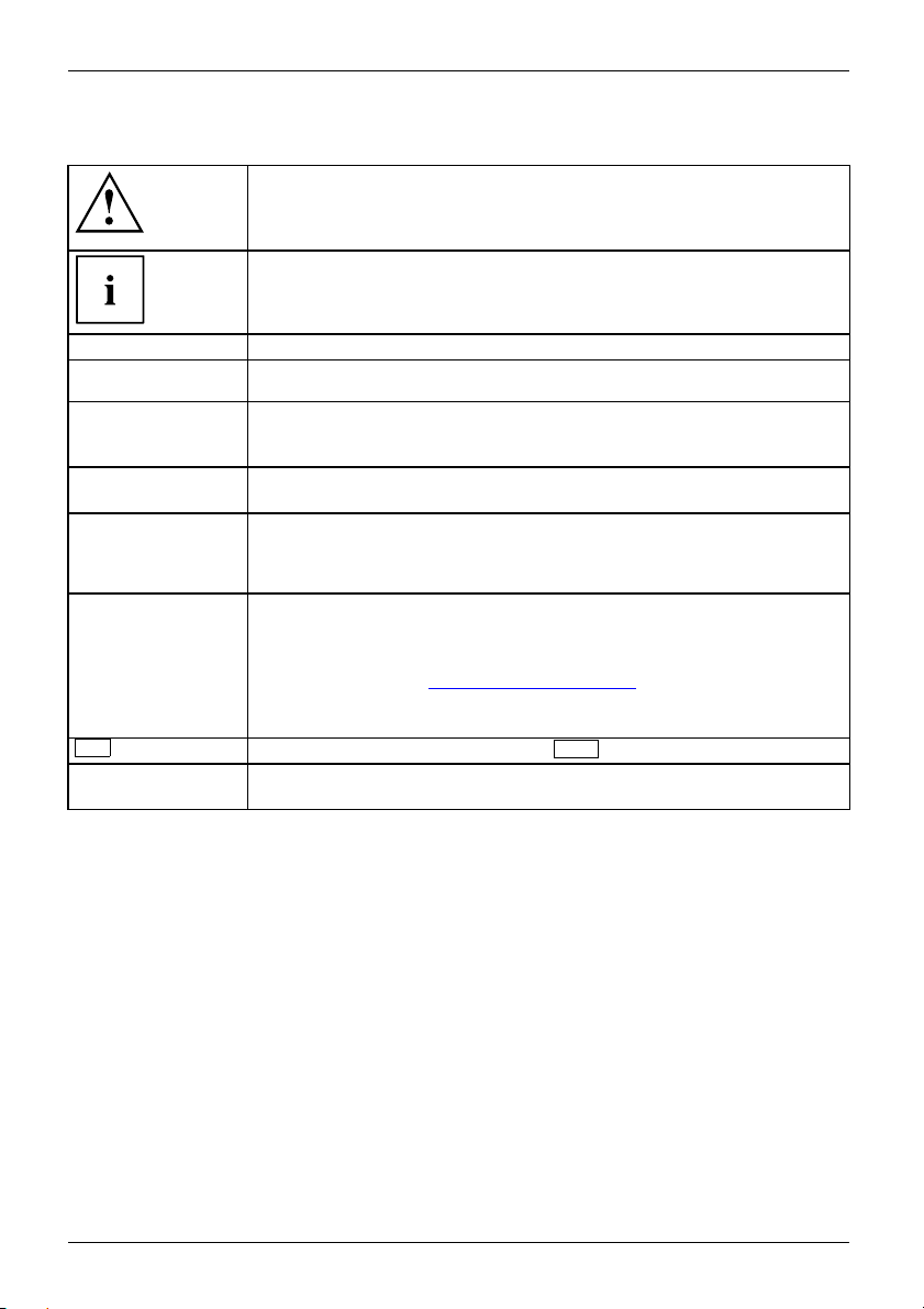
Notational conventions
Pay particular attention to text marked with this symbol. Failure to observe
these wa rnings could pose a risk to health, damage the device or lead
to loss of data. The warranty will be invalidated if the device becomes
defective through failure to observe these warnings.
Indicates important informa
tion for the proper use of the device.
►
This font
This font
This font
"This font"
Key
This font
Indicates an activity that must be performed
Indicates a result
indicates data entered
the command line, e.g.
start a program (star
indicates information that is displayed on the screen by a program, e.g.:
Installation is complete.
indicates
• terms and texts used in a software interface, e.g.: Click on Save
• names of programs or files, e.g. Windows or setup.exe.
indicates
• cross-references to another section, e.g. "Safety information"
• cross-references to an external source, e.g. a web address: For more
information, go to "
• Names of CDs, DVDs and titles or designations for other materials,
e.g.: "CD/DVD Drivers & Utilities" or "Safety/Regulations" manual
indicates a key on the keyboard, e.g:
indicates terms and texts that are emphasised or highlighted, e.g.: Do
not switch off the device
using the keyboard in a program dialogue or at
your passwor d (Name123) or a command used to
t.exe)
http://www.fujitsu.com/fts"
F10
6 Fujitsu
Page 11
Important notes
ImportantnotesNotes
In this chapter you will find information regarding safety which it is essential to
take note of when working with your device.
Safety information
SafetyinformationNote
Please note the informat
and in the following safe
When installing and ope
environmental conditi
as the instructions in C
When setting up the dev
thecasingreceives
cover the ventil ati
You must only opera
device is set to the
The main switch (if
device from the ma
voltage, remove t
Only operate th
Replace the lit
in "
Replacing t
Caution, comp
The activiti
performed wi
Repairs to th
Incorrect r
to the equi
e device with the casing closed.
hium battery on the mainboard in accordance with the instructions
he lithium battery", Page 42.
onents in the system can get very hot.
es described in these instructions must always be
th the greatest care.
e device must only be performed by qualified technicians.
epairs could put the user at great risk or cause serious damage
pment (electric shock, risk of fire).
ion provided in the "Safety/regulations" manual
ty notes.
rating the device, please observe the notes on
ons in Chapter "
hapter "
Tec hnical specification", Page 43 as well
Getting started", Page 11.
ice, make sure there is clearance all around it so that
enough ventilation. I n order to avoid overheating, do not
on areas of the monitor or the device.
te th e device if the rated voltage used by the
local mains voltage.
present) and the ON/OFF switch do not disconnect the
ins voltage. To completely disconnect from the mains
he power plug from the power socket.
Important notes
Transpor
rtation
portation
Device,Transpo
Retrans
ting the device
Transport all parts separately in their original packaging or in a packaging which
protects them from knocks and jolts, to the new site.
Do not unpack them until all transportation manoeuvres are completed.
If the device is brought from a cold environment into the r oom where it will b e used,
condensation may occur. Before operating the device, wait until it is absolutely dry
and has reached ap proximately the same temperature as the installation site.
Fujitsu 7
Page 12

Important notes
Cleaning the device
Device,Transporta tionRetransportationSystemunit,seeDevice
Turn off all power and equipm ent switches and disconnect the power
plug from the m ains outlet.
Do not clean any interior parts yourself, leave this job to a service technician.
Do not use any cleaning agents that contain abrasives or may corrode
plastic (alcohol, thinner or acetone).
Never clean the device with water! Water entering into the device could
present a serious risk to users (e.g. electric shock).
Ensure that no liquid enters the system.
The surface can be clea
moistened in mild dome
Use disinfectant wi
ned with a dry cloth. If particularly dirty, use a cloth that has been
stic detergent and then carefully w rung out.
pes to clean the keyboard and the mouse.
Energy saving, disposal and recycling
DisposalEnergysavingRecyclingDrivers&UtilitiesDVDUserDocumentationDVD
You c an findinformationonthesesubjectsinthe"Environment and Energy Information" manual
or on our website ("
http://www.fujitsu.com/fts/about/fts/environment-care/").
8 Fujitsu
Page 13

Important notes
CE marking
CEmarkingCEmarkingNotesElectromagneticcompatibilityLowvoltagedirective
The shipped version of this device complies with the requirements of EU directives 2004/108/EC
"Electromagnetic compatibility", 2006/95/EC "Low voltage directive", 2011/65/EC "RoHS directive"
and 2009/125/EC "ecodesign directive".
CE marking for devices with radio component
This equipment complies with the requirements of Directive 1999/5/EC o f the E urop ean Parliament
and C ommission from 9 March, 1999 governing Radio and Telecommunications Equipment
and mutual recognition of conformity.
CE nnnn (!) ; nn nn: For digits and exclamation mark (!), see label on the product.
You ca n find more information and declarations of conformity on the Internet at:
http://globalsp.ts.fujitsu.com/sites/certificates".
"
This equipment can be used in the following countries:
Belgium Bulgaria Denmark
Estonia Finland France
UK Ireland Iceland Italy
Croatia
Latvia Liechtenstein Lithuania
Luxembourg Malta Netherlands Norway
Austria Poland Portugal Rumania
Sweden Switzerland Slovakia Slovenia
Spain
Turk ey
Czech Republic
Cyprus
Contact th
possible o
the corres
your coun
e corresponding government office in the respective country for current information on
perating restrictions. If your country is not included in the list, then please contact
ponding supervisory authority as to whether the use of this product is permitted in
try.
Germany
Greece
Hungary
Fujitsu 9
Page 14

Important notes
FCC Compliance Statement
If the device complies with the FCC regulations, the FCC sign can be found on the type rating plate.
FCC Class B Compliance State
DOC (INDUSTRY CANADA) NOTICES
Notice to Users of Radios and Television :
This class B digital apparatus complies with Canad ian ICES-003.
The following statement applies to the products covered in this manual, unless otherwise specified
herein. The statement for other products will appear in the accompanying documentation.
NOTE:
This equipment has been tested and found to com ply with the limits for a "Class B" digital
device, pursuant to Part 15 of the FCC rules and meets all requirements of the Canadian
Interference-Causing Equipment Standard ICES-003 for digital apparatus. These limits are
designed to provide reasonable protection against harmful interference in a residential installation.
This equipmen t generates, uses and can radiate radio frequency energy and, if not installed
and used in strict accordance with the instructions, may cause harmful interference to radio
communications. However, there is no guarantee that interference w ill not occur in a particular
installation. If this equipment does cause harmful interference to radio or television reception,
which can be determined by turning the equipment off and on, the user is encouraged to
try to correct the interference by one or more of the following measures:
• Reorient or relocate the receiving antenna.
• Increase the s
• Connect the equipment into an outlet on a circuit different from that to
which the receiver is connected.
• Consult the d
Fujitsu not responsible for any radio or television interference caused by unauthorized modifications
of this equipment or the substitution or attachment of connecting cables and equipment other
than those specified by Fujitsu. The correction of interferences caused by such unauthorized
modification, substitution or attachment will be the responsibility of the user.
The use of shielded I/O cables is required when connecting this equipment to any and all optional
peripheral or host devices. Failure to do so may violate FCC and ICES rules.
eparation between equipment and the r ece iver.
ealer or an experienced radio/TV technician for help.
ment
FCC Radiation Exposure Statement
This equipment complies with FCC radiation exposure limits set forth for an uncontrolled environment.
The transmitters in this device must not be co-located or operated in conjunction
with any other antenna or transmitter.
To prevent radio interference to the licensed service, this device is intended to be
operated indoors and away from windows to provide maximum shielding. Equipment (or
its transmit antenna) that is installed outdoors is subject to licensing.
Users are not authorized to modify this product. Any modi fications invalidate the warranty.
This equipment may not be modified, altered, or changed in a ny way without signed
written permission from Fujitsu. Unauthorized modification will void the equipment
authorization from the FCC and Industry Canada and the warranty.
10 Fujitsu
Page 15
Getting started
Getting started
Gettingstarted
Unpacking and checking the delivery
It is recommended not to throw away the original packaging material! It may be
required for reshipment at some later date.
PackagingContentsofdeliveryPackaging,
► Unpack all the individual parts.
► Check the contents of the package for any visible damage caused during transport.
► Check whether the delivery conforms to the details in the delivery note.
► Should you discover that the d elivery does not correspond to the delivery
Steps for initial setup
Preparingforfirstuse,overvie wPreparingforuse,
Only a few steps are necessary to put your new device into operation for the first time:
• Select a location for device and set up device
• Connect external devices such as mouse, keyboard and monitor
• Check the voltage at the mains outlet and connect the device to an electrical outlet
• Switch the device on
You will learn more about the individual steps in the following sections.
Please observe the safety information in the "Important notes", Page 7 chapter.
note, notify your local sales outlet immediately.
External devices
If you have received other external devices in addition to your own device (e.g.
a printer), do not connect these until after the initial installation. The following
sections describe how to connect these external devices.
Drives and boards
If you have received drives or boards with your device, please do not install
them until after first-time setup. How to install drives and boards is described
System expansions", Page 28 chapter.
in the "
Fujitsu 11
Page 16

Getting started
Setting up the device
WorkstationErgonomicDevice
When installing your device, please read the recommendations and safety
notes in the "Safety/regulations" manual.
We recommend that you place your device on a surface which is not slippery. In
view of the many different finishes and varnishes used on furniture, it is possible
that the rubber feet will mark the surface they stand on.
Depending on the location of your device, bothersome vibrations and noises may
occur. To prevent this, a distance of at least 10 mm / 0.39" should be maintained
from other devices on casing sides without ventilation surfaces.
In order to avoid overheating, do not cover the ventilation areas
of the monitor or the device.
A minimum distance of 200 mm / 7.87" from the device must be
observed for ventilation areas.
Do not stack several devices on top of each other.
Do not expose the device to extreme ambient conditions (see "
specification", Page 43, section "Ambient conditions"). Protect the
device against dust, humidity and heat.
Technical
Operating positi
Use the device on
on
ly in the vertical operating position.
Connecting the device to the mains supply
Mainsadapter
1
2
► Conn
► Plug the power plug into a grounded mains outlet (2).
ect the power cable to the device (1).
12 Fujitsu
Page 17

Getting started
LAN
Connecting external devices
Read the documentation on the external device before connecting it.
With the exception of USB devices, always remove all power plugs
before connecting external devices!
Do not connect or disconnect cables during a thunderstorm.
Always take hold of the actual plug. Neve r unplug a cable by pulling the cable itself.
Ports on the device
InterfacesExternaldevicesDevice
The ports are located on the front and back of the device. The ports available on your
device depend on the configuration level you have selected. The standard ports are
marked with the symbols shown below (or similar). Detailed information on the location
of the ports is provided in the manual for the mainboard.
The ports available on your device depend on the selected device confi gurat ion level.
DVI monitor port, white
Monitorport
VGA monitor port, blue
Monitorport
Microphone jack
Microphoneport
Headphones port
Headphones
USB 2.0 - Universal Serial
Bus, black
Audio input (Line In)
AudioinputLi nein
Audio output (Line Out)
AudiooutputLineout
LAN port
LANport
USB 3.0 - Universal Serial
Bus, blue
UniversalSerialBus
Keyboard port, purple
Keyboardport
S/PDIF port
e-Sata
PS/2 mouse port, green
MouseportPS/2mouseport
e-SATA port
Serial port, turquoise
Serialport
S/PDIF
DP DisplayPort
Some of the peripherals require special software (e.g. drivers) (refer to the
documentation for the periphera l and operating system).
Fujitsu 13
Page 18

Getting started
Connecting a monitor
► Follow the instructions contained in the monitor manual to prepare the monitor
for operation (e.g. connecting cables).
Monitor
► Connect the data cable of the monitor into the monitor port of your device.
The optional monitor power cable may only be connected to the monitor socket of
the device if the monitor current consumption is less than 1 A with 240 V or 2 A
with 100 V. The values for the monitor current consumption can be found in the
technical data on the monitor or in the operating manual for the monitor.
► Plug the monitor power ca
ble into the grounded mains outlet.
Connecting the mouse
You can connect a US B mouse or a PS/2 mouse to y our device.
Mouse,Connecting,
Connecting a USB mouse
► Connect the USB m ouse to one of the USB ports on the device.
USBport,USBport
Connecting a PS/2 mouse
The PS/2 mouse is only detected by the device if you connect the mouse when
the device is switched off and then switch the device on again.
► Connect the PS/
PS/2mouse,Connecting,PS/2mouse,
► Switch your device on again.
2 mouse to the PS/2 mou se port of the device.
Connecting the keyboard
You can connect a USB keyboard or a PS/2 keyboard to your device.
Keyboard,Connecting,
Connecting a USB keyboard
Use the supplied keyboard cable only.
USBport,Connecting,
► Insert the flat rectangular USB plug of the keyboard cable into one of the device’s USB ports.
USBport
Connecting a PS/2 keyboard
Use the supplied keyboard cable only.
ctingaPS/2keyboard
cting,
Conne
Conne
The PS/2 keyboard i s only detected by the device if you connect the keyboard
when the device is switched off and then switch the device on again.
► Switch your device off.
► Plug t
he rou nd plug of the keyboard cable into the keyboard po rt on the device.
Keyboard,
► Switch your device on again.
14 Fujitsu
Page 19

Connecting external devices to the serial interface
SerialinterfaceSerialinterface,Externaldevices,Devices,
External d evices (e.g. a printer or scanner ) can be connected to the serial port.
► Connect the data cable to the external device.
► Connect the data cable to the corresponding serial interface.
For an exact description of how to conne ct external devices to the corresponding
port, please see the external device documentation.
Port settings
Serialinterface,
Device drivers
Devicedrivers,
Connecting external devices to the USB ports
USBdevices,USBport,Externaldevices,D evices,
You can connect a wide range of external devices to the USB ports (e.g.
printer, scanner, modem or keyboard).
You can change the port settings (e.g. address, interrupt) in the BIOS Setup.
The devices connected to the serial interface require drivers. Your operating system
already includes many drivers. If the required drive is missing, install it. The latest
drivers are usually available on the Internet or will be supplied on a data carrier.
Getting started
USB devices are hot-pluggable. This means you can connect and disconnect
USB cables while your device is switched on.
Additional information can be found in the documentation for the USB devices.
► Connect the data cable to the external device.
► Connect the d
ata cable to one of the U SB ports on your device.
Device drivers
The extern
own, as the
requires
Fujitsu 15
al USB devices you connect to the USB ports usually require no driver of their
required software is already included in the operating system. If the device
separate software, please note the information in the manufacturer’s manual.
Page 20

Getting started
Switching on for the first time: installing the software
Installing,Software,Installing,
Once the installation has been started the device must not be switched
off, unless the installation has been completed.
During installation, the device may only be rebooted when you are requested to do so!
The installation will otherwise not be carried o ut correctly and the contents
of the hard disk must be completely restored.
If the device is integrat
the network protocol ar
Contact your network ad
When you switch on the d
is installed and config
as this process must n
You may need th e lic
number as a label on
ed into a network, the user and server details as well as
e required during the software installation.
ministrator if you have any questions about these settings.
evice for the first time, the supplied software
ured. Plan a reasonable amount of time for this,
ot b e interrupted.
ence number for Windows during the installation. You can find the licence
your device (no longer applies to Windows 8 or higher).
16 Fujitsu
Page 21

Switching on monitor and device
In order to avoid overheating, do not cover the ventilation areas
of the monitor or the device.
Depending on the version, the device may be equipped with a main power switch
on the back of the device in addition to the ON/OFF button on the front.
► Switch the monitor on (see the operating manual for the monitor).
► Switch the device on. To do this, follow the instructions below.
Getting started
1
2
► Turn the main switch on the back of the device to the "I" position (1).
► Press the ON
The power indicator lights up and the device is started.
/OFF switch on the front of the device (2).
Installing the software
► During installation, follow the on-screen instructions.
ing,
Software,Install
► If anything is unclear regarding the data you are asked to input, read the
online Help in your operating system.
You wil l find more information on the system, a s well as drivers, utilities and updates on
the "Drivers & Utilities" DVD and on the Internet at "
You c a n find information and help on the Windows operating system functions
on the Internet at "
http://windows.microsoft.com".
Fujitsu 17
http://www.fujitsu.com/fts/support".
Page 22

Operation
Operation
Switch the device on
► If necessary, switch the monitor on (see the operating manual for the monitor).
Device,Monitor,
► Switch on the device using t
► Press the ON/OFF switch on the front of the device.
The power indicator glo
Switching off the device
► Shut down the operating system in a defined manner. In Windows: via the
Start menu and the Turn Off Computer function.
Device,Monitor,
► If the operating s y
switch it off, pres
If the device is switched off, it consume s a minimum of energy.
► Switch the device
The device no longer uses any power.
The main switch and the ON/OFF switch do not disconnect the device
from the mains voltage. To completely disconnect from the mains voltage,
remove the power plug from the power socket.
stem does not automatically switch the device into energy-saving mode or
s the ON/OFF switch. Warning, this could lead to a loss of data!
off at the main switch (if present).
he main power switch located on the rear of the device (if present).
ws and the device starts.
► If necessary, switch the monitor off (see the operating manual for the monitor).
18 Fujitsu
Page 23

Indicators on the device
Indicators,Device
The indicators are o n the front of the casin g. Which indicators are available on your
device depends on the configuration level you have selected.
1
2
3
Operation
1 = D rive indicator, e.g. DVD
2 = Power-on indicator
No. Indicator Description
1 Drive indicator
The indicator lights up when the CD-ROM or DVD drive in the
device is accessed. Never under any circumstances remove the
CD/DVD while the indicator is lit.
2 Power-on indicator
Caution: When energy saving mode is active, the device must
not be switched off at the main power switch (if present) or
disconnected from the mains, as this may result in data loss.
• The indicator is illuminated:
The device
• The indicator is flashing:
The devic
with the O
state it w
• The indicator is not lit:
The dev
3Harddi
sk indicator
The indicator lights up when the hard disk drive of the device is
accessed.
3 = Hard disk indicator
is sw itched on.
e is in energy-saving mode. After being switched on
N/OFF switch, the device powers up or returns to the
as in be fore it entered energy-saving mode.
ice is switched off.
Fujitsu 19
Page 24

Operation
Keyboard
KeyboardKeyboard,Keyboard,Keyboard,Keyboar d,Keyboard,AlphanumerickeypadCursorkeysKeys,Function keysN um erickeypadNumerickey pad
The illustrated keyboard is an example and may differ from the model you use.
1 2
345
1 = Function keys
2 = On/off switch (optional)
4=Cursorkeys
5 = Numeric keypad (calculator keypad)
3 = Alphanumeric keypad
Important k
KeysKeyb oardshortcuts
eys and keyboard shortcuts
The description of the following keys and keyboard shortcuts applies to Microsoft
operating systems. Details of other keys and keyboard shortcuts can be found in
the documentation for the relevant application program.
Key / key combination Description
tch
ON/OFFswi
Button,
On/off switch (optional)
Depending on the setting in the BIOS Setup, the device can be switched
on or off with this switch. Some operating systems allow you to configure
additional functions of the ON/OFF switch in the Control Panel.
WithsomekeyboardstheON/OFFswitchcanonlybeusedwithanACPI
(Advanced Configuration and Power Manageme n t Interface). Otherwise
the key is inoperative. The m ainboard must support this function.
Keys,Keys,Keys,
Enter key
confirms the highlighted selection. The Enter key is also referred to as
the "Return" k ey.
20 Fujitsu
Page 25

Operation
Key / key combination Description
Keys,
Windows key (device-dependent
calls up the Windows Start menu
Keys,
Menu key (device-dependent:
calls up the menu for the marke
Keys
Windows key (device-depe
Switches between the star
Keys
Menu key (device-dependent: variant 2)
Opens the menu for the active application.
Keys,Keys,
Shift key
enables upper-case
Keys,
Alt Gr key (country
produces a charac
sign on the
Keys,
Num Lock key
By pressing the
lower-case lev
When the Num Lo
keys are activ
When the Num L
Numeric keyp
Keys,KeysKeysKeys,
Ctrl key
Ctrl
performs a special operation when pressed in conjunction with another
key. The
Ctrl+Alt+DelCtrl+Alt+DelKeyskeyboardshor tcuts
Ctrl
Windows Security/Task Manager
AltCtrl
++
Del
This key combination opens the Windows Security/Task Manager window.
:variant1)
.
variant 1)
d item (Windows).
ndent: variant 2)
t screen and the last used application.
letters and the upper key symbols to be displayed.
-dependent)
ter shown on the bottom right of a key (e.g. the @
Q
key).
Num Lock key you switch between the upper- and
els of the calculator keypad.
ck indicator is lit the numeric keypad and arithmetic
e.
ock indicator is not lit the cursor control functions on the
ad are active.
key is a lso called the "Control" or "Control key".
Settings in BIOS Setup
etup,
msettings,
etup,
etup,
etup
,
BIOSS
Syste
BIOSS
BIOSS
BIOSS
Setup
In BIOS Setup, you can set the system functions and the hardware configuration of the device.
When the PC is delivered, the default entries are valid (see "BIOS Setup" manual or manual for
the mainboard). You can customise these settings to your requirements in the BIO S Setup.
Fujitsu 21
Page 26

Operation
Property and data protection
PropertyprotectionDataprotectionSecuritymeasures
Software functions and mechanical locking offer a broa d range of functions for protecting your device
and your personal data against theft and unauthorised access. You can also combine these functions.
Anti-theft protection and lead-sealing
Device,Device,Casing,Lead-sealingAnti-theftprotectionKensingtonLockChain
1
2
1 = Device for Sec
Anti-theft pr
You can prote
•withtheSec
consult the
otection
ct your device from theft
urity Lock device (1) and a Kensington MicroSaver. Please
manual for your Security Lock.
urity Lock
2 = Holes for padl
ock
• with the holes (2) and a padlock and chain which you have connected to a fixed object beforehand.
Lead-sealing
To prevent unauthorised pe rsons from opening the system unit, the casing can be lead-sealed. To
do this, feed the sealing chain through the holes (2) and seal the chain with the lead seal.
22 Fujitsu
Page 27

BIOS setup security functions
Securityfunctions,BIOSSetup,
The Security menu in BIOS Setup offers you various options for protecting your
personal data against unauthorized access, e.g.:
• Preventing unauthorised access to BIOS Setup
• Preventing unauthorised system access
• Preventing unauthorised acce ss to the settings of boards with their own BIOS
• Issuing virus warnings
• Protecting BIOS from overwriting
• Protecting the device from being switched on by an external device
You can also combine these functions.
You will find a detailed description of the Security menus and ho w to assign passwords
in the manual for the mainboard or in the "BIOS Setup" manual.
Access authorisation via SmartCard
SecurityfunctionsAccesspermission,SmartCard
In systems equipped
users who have a cor
with a SmartCard reader, access can be restricted to those
responding SmartCard.
Operation
Fujitsu 23
Page 28

Troubleshooting and tips
Troubleshooting and tips
Refer to the safety notes in the "Safety/regulations" manual and in the "Getting
started", Page 11 chapter when connecting or disconnecting cables.
If a fault occurs , t ry to c
• in this chapter
• in the documentation for the connected devices
• in the help systems of th
• in the documentation for your operating system
orrect it as described in the following documentation:
esoftwareused
Help if problems occur
Should you encount
► Note the ID number
plate on the back,
► For further clarificat ion of the problem, contact the Service Desk for your country (see the
Service Desk list or visit the Internet at "
you do this, please have ready the identity number and serial number of your system.
er a problem with your computer that you cannot resolve yourself:
of your device. The ID number is found on the type rating
the underside or the top of the casing.
http://support.ts.fujitsu.com/contact/serv icedesk"). When
Troubleshooting
Power indica tor remains off after you have switched on your device
Cause
The mains voltage supply is faulty. ► Check that the power cable is correctly
Internal power supply overloaded.
Remedy
plugged into the device and into a grounded
mains outlet.
► Check that the main switch at the re ar of the
device is set to the "I" position.
► Switch the device on.
► Pull the power plug of the device out of the
mains outlet.
► Wait fo
► Plug the power plug into a properly grounded
► Swit
r about 3 minutes.
mains outlet again.
ch the device on.
24 Fujitsu
Page 29

Troubleshooting and tips
The device cannot be switched off with the ON/OFF switch.
Cause
System crash ► Keep the on/off switch pressed for at least 4
Remedy
seconds until the machine switches off.
Caution: This can lead to a loss of data!
This procedure does not allow the operating
system to shut down in an orderly way. The next
time the system is started there may well be
error messages.
Monitor remains blank
Cause
Monitor is switched off ► Switch your monitor on.
Power saving has been activated (screen is
blank)
Brightness control is set to dark ► Adjust the brightness control. For detailed
Power cable not connected
Monitor cable not connected
Incorrect setting for the monitor
Remedy
► Press any key on the ke yboard.
or
► Deactivate the screen saver. If
necessary, enter the appropriate
password.
information, please refer to the operating
manual supplied with your monitor.
► Switch off the monitor and the device.
► Check that the monitor power cable is
properly connected to the monitor and to
a grounded mains outlet or to the monitor
socket of the device.
► Check that th e device power cable is
properly plugged into the device and a
grounded m ains outlet.
► Switch on the monitor and the device.
► Switch of
► Check that the monitor cable is properly
connected to the device and monitor.
► Switch o
► Restar
► Press
► Start
► Set up the monitor as described in the
documentation for your operating system
and monitor.
f the monitor and the device.
n the monitor and the device.
t the system.
8
F
while the system is booting.
the system in Safe Mode.
Fujitsu 25
Page 30

Troubleshooting and tips
No mouse pointer displayed o n the screen
Cause
The mouse is not correctly connected.
The mouse controller is not enabled.
Remedy
► Shut down the operating system properly.
► Switch the device off.
► Check that the mouse cable is properly
connected to the system unit. If you use an
adapter or extension lead with the mouse
cable, check the connections.
► Switch the device on.
► Check in the BIOS-Setup w
controller is enabled.
► Check that the mouse driver is properly
installed and is present when the application
programme is started. Detailed information
can be found in the user guide for the mouse
and application programme.
Time and/or date is not correct
Cause
Time and date are incorrect.
The lithium battery is discharged.
Remedy
► Set the correct ti
operating syste
or
► Set the correct time and/or date in the
BIOS Setup.
► If the time and
when you switc
lithium batt
battery", P
ery (see "
age 42).
hether the mouse
me and date within the
m you are using.
date are repeatedly wrong
h on your device, replace t he
Replacing the l ithium
Error mess
Error messages and their explanations are provided:
• in the technical manual for the mainboard
• in the doc
ages on the screen
umentation for the programs used
Installing new software
When installing programs or drivers, important files may be overwritten and modified. To
be able to access the original data in the event of any problems following installation,
you should backup your hard disk prior to installation.
26 Fujitsu
Page 31

Troubleshooting and tips
Restoring hard disk contents
Should you need to restore your hard disk, the instructions a re provided on the case
of the "Recovery DVD" (delivered with your system).
Tips
Topic Tip
Outofsystemresources ► Close u nnecessary applications.
or
► Run the applications in a different order.
Other manuals Further manuals are provided as PDF files on
the "Drivers & U tilities" DVD.
Fujitsu 27
Page 32

System expansions
System expansions
Upgrades,Device,SystemexpansionCom ponentsServicing
After consulting the Hotline/Help Desk, you may remove and install the components
described in this manual yourself.
The following illustrations may differ slightly from your device, depending on its configuration level.
If further d ocu mentation was delivered with your device, please also read this through carefully.
In addition, before removing or installing system components, please pay attention to the following:
Repairs to the device must only be performed by qualified technicians. Incorrect repairs
may greatly endanger the user (electric shock, fire risk) and will invalidate your warranty.
As the de vice has to be shut down in order to install/deinstall system hardware
components, it is a good idea to print out the relevant sections of this chapter beforehand.
The device must be switched off when installing/rem oving the system
expansions and may not be in energy-saving mode.
Remove the power plug before opening the device.
Be careful that no wires become trapped when removing or installing components.
When installing components that become very hot, make sure that the maximum
permissible te mperature of the components in operation is not exceeded.
An update of the BIOS may be required for a system expansion or hardware
upgrade. Further information can be found in the BIOS help s ection or if
necessary in th e Technical Manual for the mainboard.
28 Fujitsu
Page 33

System expansions
Information about boards
Take care with the locking mechanisms (catches and centring pins) when you
are replacing boards or components on boards.
Note that some components on the mainboard may be very hot if the device was
in use shortly before the casing was removed.
To prevent damage to the board or the components and conductors on it, please take care when
you insert or remove boards. Make sure expansion boards are i nserte d straightly.
Never use sharp objects (screwdrivers) for leverage.
Boards with electrostat
shown.
When handling boards fit
following points:
• You must always disc
object) before work
• The equipment and tools you use must be free of static charges.
• Only touch or hold t
marked green (Touc
• Never touch pins or conductors on boards fitted with ESDs.
ic sensitive devices (ESD) are identifiable by the label
ted with ESDs, you must always observe the
harge static build up (e.g. by touching a grounded
ing.
he boards by the edge or, if present, at the areas
h Points).
Fujitsu 29
Page 34

System expansions
Opening the casing
Casing,Device,
► Switch the device off. The device must not be in power-saving mode.
Please observe the safety information in "Important notes", Pag e 7.
Disconnect the mains plug from the mains outlet.
Only insert the power plug after you have closed the casing.
► Remove any connected wir
es which are in the way.
► Lay the device on its side in the manner show n below.
1
2
1
1
► Remove the casing screws (1).
► Slide the side cover from the casing in the direction of the arrow (2).
30 Fujitsu
Page 35

Closing the casing
► Insert the side part in the guide rail on the lower part of the casing.
Casing,Device,
1
2
2
► Slide the side cover onto the casing in the direction of the arrow (1).
► Tighten the casing screws (2).
► Reconnect the cables that you disconnected before.
System expansions
Overview of the drive bays and drives in your device
The casing has space for several accessible and non-accessible drives:
• two drive bays for accessible 5
• one drive bay for an accessible 3
• two drive bays for non-accessible 3
"Accessible drives" are e.g. DVD or CD ROM drives, into which a data medium can be
inserted from outside. "Non-accessible drives" are for e xamp le hard disk drives.
Fujitsu 31
1
/4inch drives
1
/2inch drive
1
/2"or21/2"drives.
Page 36

System expansions
Installing and removing the accessible 51/4inch drive
Removing an accessible drive
► Open the casing (see "Opening the casing", Page 30).
Accessibledri ve,Drive,
► Disconnect the cables conne
cted to the drive.
1
1
2
► Loosen the scr
► Working from behind, slide the drive a short distance out of the bay in the direction of the arrow (2).
The drive now
► Pull the drive out of the casing (2).
► If necessar
ews (1).
protrudes slightly out of the casing.
y, make the required settings on the remaining hard disk drive.
Installing an accessible drive
► Open the casing (see "Opening the casing", Page 30).
Diskettedrive,Diskettedrive,
► If there is an accessible drive, please remove it (see "Removing an accessible drive", Page 32).
► Remove the front panel from the casing.
► From the inside, press the plastic drive cover out of the front panel.
32 Fujitsu
Page 37

System expansions
1
► Break out the pre-stamped metal c over on the drive bay opening with a screwdriver (1).
► Secure the front panel on the casing again.
2
2
1
► Slide the
► Fasten the drive into place with the screws (2).
► Plug the
► If there is an acce ssible drive, please install it again.
► Close t
Fujitsu 33
drive into the casing (1). Make sure that the screw holes are aligned.
data and the power supply connectors into the drive. Make sure the polarity is correct.
he casing (see "
Closing the casing", Page 31).
Page 38

System expansions
Installing and removing an accessible 31/2inch drive
Installing an accessible dri
► Open the casing (see "Opening the casing", Page 30).
Diskettedrive,Diskettedrive,
► If there is an accessible 51/
an accessible drive", Page
► Remove the front panel from the casing.
► From the inside, press th
► Break out the
► Secure the front panel on the casing again.
pre-stamped metal cover on the drive bay opening with a screwdriver (1).
" drive, remove the drive (see "Removing
4
32).
e plastic drive cover out of the front panel.
ve
1
2
2
1
► Slide the drive into the casing (1). Make sure that the screw holes are aligned.
► Fasten the drive into place with the screws (2).
► Plug the data and the power supply connectors into the drive. Make sure the polarity is correct.
34 Fujitsu
Page 39

System expansions
► Ifthereisanaccessible51/4" drive, reinstall the drive.
► Close the casing (see "
Closing the casing", Page 31).
Removing an accessible drive
► Open the casing (see "Openin
► Disconnect all cables connected to the drive (data cable, power supp ly cable).
g the casing", Page 30).
1
1
2
► Remove the screws (1).
► Slide the drive o ut of the bay from behind, in the direction of the arrow (2).
► Close the casing (see "
Fujitsu 35
Closing the casing", Page 31).
Page 40

System expansions
Installing and removing the har
Harddiskdrive,Harddiskdrive,Harddiskdrive,
ddiskdrive
Removing a hard disk drive
► Open the casing (see "Opening the casing", Page 30).
Harddiskdrive,
► Remove all connected cables (data cable, power supp ly) from the drive.
1
1
1
1
2
► Undo the screws (1) and gently press against the hard disk drive from underneath.
► Pull the drive backwards a short way out of the bay in the direction of the arrow (2).
The drive now protrudes slightly out of the bay.
► Pull the drive completely out of its bay. Make sure that you are not touching other components.
► If necessary, make the required settings on the remaining hard disk drive.
► Close the casing (see "
Closing the casing", Page 31).
It may be necessary to modify the entry for the remaining drives in the BIOS Setup.
You will need a SATA cable to install a second hard disk on the listed device variants.
36 Fujitsu
Page 41

System expansions
Installing a hard disk drive
► Open the casing (see "Opening the casing", Page 30).
Harddiskdrive,
► Take the new hard disk drive out of its packaging.
2
2
2
2
1
► Slide the hard disk drive into the casing (1). Make sure that the screw holes are aligned.
► Press gently against the hard disk drive from below and secure it with the screws (2).
► Connect the cables (da ta cable, power supply) to the drive.
Check that the polarity is correct and do not use any force.
► Close the casing (see "
Closing the casing", Page 31).
Fujitsu 37
Page 42

System expansions
Installing and removing a board
You can install additional modules in order to increase the performance of your machine.
The number, position and arrangement of the board slots on the mainboard can be found in
the manual for the mainboard. Boards may already be installed on shipment.
Board,Board,
Board installing
► Open the casing (see "Opening the casing", Page 30).
Board,
2
1
► Remove the screw (1) from the cover plate (1).
► Remove the cover plate from the casing in the direction of the arrow (2).
1
2
► Remove the screw on the slot cover (1).
► Pull the slot cover out of th e slot in the direction of the arrow (2).
38 Fujitsu
Page 43

System expansions
Do not throw away the slot cover. For cooling, protection against fireandinorderto
comply with E MC regulations, you must refit the slot cover if you remove the board.
2
1
► Push the board in
► Tighten the screw on the slot cover (2).
► Secure the cove
► If necessary, connect the cables to the board.
► Close the casi
If you have in
slot setting
informatio
Board remo
► Open the casing (see "Opening the casing", Page 30).
Board,
► Remove th
► Disconnect the cables connected to the board.
Fujitsu 39
to the slot (1).
r plate on the casing again.
ng (see "
Closing the casing", Page 31).
stalled or removed a board, please check the relevant PCI
sintheBIOS Setup. If necessary, change the settings. Further
n is provided in the PCI board documentation.
ving
e cover plate (see "
Board installing", Page 38).
Page 44

System expansions
1
2
► Remove the screw on the board (1).
► Pull the board out of the slot in the direction of the arrow (2).
► Place the board in suitable packaging.
For cooling, protection against fire, and in order to comply with EMC (electromagnetic
compatibility) regulations, you must refit the slot cover.
2
1
► Slide the slot cover into the slot (1).
► Secu
► Secure the cover plate on the casing again.
40 Fujitsu
re the slot cover in position with the screw (2).
Page 45

System expansions
► Close the casing (see "Closing the casing", Page 31).
If you have installed or removed a PCI board, please check the relevant PCI
slot settings in the BIOS Setup. If necessary, change the settings. Further
information is provided in the P CI board documentation.
Mainboard expansions
Details on how to upgrade the main memory or the processor of your device
can be found in the manual for the mainboard.
UpgradesLithiumb atteryProcessorMainmemoryMainboard
Upgrading main memory
► Open the casing (see "Opening the casing", Page 30).
Mainmemory,
► Upgrade the memory according to the description in the manual for the mainboard.
► Close the casing (see "
Processor, replacing
► Open the casing (se
acing
Processor,repl
► Upgrade the processor according to the description in the manual for the mainboard.
► Close the casing
Closing the casing", Page 31).
e "
Opening the casing", Page 30).
(see "
Closing the casing", Page 31).
Fujitsu 41
Page 46

System expansions
Replacing the lithium battery
In order to permanently save the system information, a lithium battery is installed to provide
the CMOS-memory with a current. A corresponding error message notifies the user when the
charge is too low or the battery is empty. The lithium battery must then be replaced.
Incorrect replacement of the lithium battery may lead to a risk of explosion!
The lithium battery may be replaced only with an identical battery or with
a type recommended by the manufacturer.
Do not dispose of lithium batteries with household waste. They must be disposed
of in accordance with local regulations concerning special waste.
Make sure that you observe the correct polarity when replacing the lithium
battery. The plus pole must be on the top!
Lithiumbattery,Replacing,Replacing,Replacing,lithiumbatteryBattery
The lithium battery holder exists in different designs that function in the same way.
1
2
2
1
3
► Press the catch in the direction of the a rro w (1).
The battery jumps out of the holder slightly.
► Remove the battery (2).
► Push the new lithium battery of the identical type into the holder (3) and
press it down until it engages.
3
42 Fujitsu
Page 47

Technical specification
Technical specification
Electrical data
Safety standards complied with: IEC 60950–1, EN 60950–1, UL 60950 CSA 22.2
Protection class: I
Rated voltage range: 100 – 240 V
Rated frequency:
Maximum rated current (with monitor socket):
Maximum rated current (without monitor socket):
Maximum rated current (optional monitor
socket):
Dimensions
Width/depth/height: 175 mm x 417 mm x 354 mm /
Weight
in basic configuration: approx. 8 kg / 17.63 lbs
Environmental conditions
Environment class (3K2):
Environment class (2K2):
Temperature:
Operating (3K2): 10 °C .... 35 °C /50 °F ... 95 °F
Transportation (2K2): –25 °C .... 60 °C /– 13 °F ... 140 °F
The formation of condensation is not permitted while the device is in operation !
Clearance requ ired to ensure adequate ventilation:
without air vents
with air vents
No.60950-1
50–60Hz
100 – 240 V
5.0–2.5A
100 – 240 V
3.0–1.5A
100 – 240 V
2.0–1.0A
6.88 inch x 16.41 inch x 13.93 inch
DIN IEC 721 part 3-3
DIN IEC 721 part 3-2
min. 10 mm / 0.39 inch
min. 200 mm / 7.87 inch
The data sheet for this device provides further technical data. The data sheet
can be found on our website "
Fujitsu 43
http://www.fujitsu.com/fts".
Page 48

Index
Index
A
Access permission, SmartCard 23
Accessible drive,
removing 32
Alphanumeric keypa d 20
Anti-theft protection 22
Audio input 13
Audio output 13
B
Battery 42
BIOS Setup 21
BIOS Setup,
configuration 21
security functions 23
settings 21
system settings 21
Board,
installing 38
removing 38–39
Button,
ON/OFF switch 20
C
Casing,
closing 31
Lead-sealing 22
opening 30
CE marking 9
Chain 22
Components
installing/removing 28
Connecting a PS/2 keyboard 14
Connecting,
keyboard 14
mouse 14
PS/2 keyboard 14
PS/2 mouse 14
USB keyboard 14
Contents of delivery 11
Ctrl+Alt+Del 21
Cursor keys 20
D
Data protection 22
Device
indicators 19
Ports 13
setting up 12
Device drivers,
serial interface 15
Device,
Anti-theft pro tection 22
closing 31
Lead-sealing 22
opening 30
switching off 18
switching on 18
transporting 7–8
upgrades 28
Devices,
connecting 15
Diskette drive,
removing 32, 34
replacing 32, 34
Disposal 8
Drive,
removing 32
Drivers & Utilities DVD 8
E
Electromagnetic compatibility 9
Energy saving 8
Ergonomic
Workstation 12
External devices
Ports 13
External devices,
connecting 15
F
Function keys 20
G
Getting started 11
H
Hard disk drive,
installing 36–37
removing 36
replacing 36
Headphones 13
I
Important notes 7
Indicators,
device 19
44 Fujitsu
Page 49

Index
Installing,
software 16–17
switching on for the first time 16
Interfaces 13
K
Kensington Lock 22
Keyboard 20
Keyboard port 13
keyboard shortcuts 21
Keyboard shortcuts 20
Keyboard,
alphanumeric keypad 20
connecting 14
cursor keys 20
function keys 20
numeric keypad 20
port 14
Keys 20
Ctrl 21
Ctrl+Alt+Del 21
Menu key 21
Keys,
Alt Gr 21
Control 21
Ctrl key 21
cursor keys 20
Enter 20
Enter key 20
menu key 21
Num Lock 21
Return 20
shift 21
shift key 21
Start key 21
L
LAN port 13
Lead-sealing 22
Line in 13
Line out 13
Lithium battery 41
Lithium battery,
replacing 42
Low voltage directive 9
M
Main memory 41
Main memory,
upgrading 41
Mainboard
Upgrades 41
Mains adapter
connecting 12
Microphone port 13
Monitor
connecting 14
Monitor port 13
Monitor,
switching off 18
switching on 18
Mouse port 13
Mouse,
connecting 14
N
Note
safety 7
Notes
CE marking 9
important 7
Numeric keypad 20
O
ON/OFF switch 20
Overview
Device 5
P
Packaging 11
Packaging,
unpacking 11
Preparing for first use, overview 11
Preparing for use,
overview 11
Processor 41
Processor, replacing 41
Property protection 22
PS/2 mouse port 13
PS/2 mouse,
connecting 14
port 14
R
Recycling 8
Replacing,
lithium battery 42
Replacing, lithium battery 42
Retransportation 7–8
S
Safety information 7
Fujitsu 45
Page 50

Index
Security functions
SmartCard 23
Security functions,
BIOS Setup 23
Security measures 22
Serial interface 15
Serial interface,
connecting devices 15
settings 15
Serial port 13
Servicing 28
Setup,
see BIOS Setup 21
Software,
installing 16–17
System expansion 28
System settings,
BIOS Setup 21
System unit, see Device 8
T
Transportation 7–8
U
Universal Serial Bus 13
Upgrades
Mainboard 41
Upgrades,
device 28
USB devices,
connecting 15
USB port 14
USB port,
connecting devices 15
connecting keybo a rd 14
connecting the mouse 14
User Documentation DVD 8
W
Workstation 12
46 Fujitsu
 Loading...