

Page 1

Professional Notebook English
EasyGuide
ESPRIMO Mobiles V5545/5505
Page 2

Are there ...
... any technical questions or problems?
Please contact:
• our Hotline/Help Desk (refer to the enclosed Help Desk List or go to: "
• your sales partner
• your sales office
Additional information is contained in the Help Desk list and the "Warranty" man ual. The
"Warranty" manual can be found on the "Drivers & Utilities" CD/DVD.
Latest information on our products, tips, updates etc. can be found on our
website at: "
www.pc-ap.fujitsu.com"
www.pc-ap.fujitsu.com")
Page 3

Page 4

This manual was produced by Xerox Global Services
Published by
FujitsuPCAsiaPacific Pte Ltd.
AG 12/07
Edition 1
Order no.: A26391-K240-Z220-1-7619
Page 5

ESPRIMO Mobiles V5545/5505
EasyGuide
Your ESPRIMO Mobile V 1
Important notes
Ports and operati
Removing and installing components
during servicing
Technical dat
Index
ng elements
a
3
4
15
17
18
Page 6

Adobe and Acrobat are trademarks of Adobe Systems Incorporated and may
be protected in certain countries.
DPMS a nd VESA are registered trademarks of the Video Electronics Standards Association.
The Bluetooth trademarks are the property of Bluetooth SIG, Inc., U.S.A.
and licensed to Fujitsu Limited.
Intel is a registered trademark, Pentium and Celeron are trademarks of Intel Corporation, U S A.
Kensington and MicroSaver are registered trademarks of AC CO World Corporation.
Macrovision is a trademark of Macrovision Corporation, USA.
Microsoft, MS, MS DOS, Windows, and Windows NT are registered
trademarks of Microsoft Corporation.
PS/2 is a registered trademark of International Business Machines, Inc.
All other trademarks referenced are trademarks or registered trademarks of their
respective owners, whose protected rights are acknowledged.
Copyright © Fujitsu Limited 2007
All rights reserved, including rights of translation, reproduction by printing, copying
or similar methods, in part or in whole.
In the event of violations, perpetrators will be liable to prosecution for damages.
All rights reserved, including rights created by patent grant or registration of a utility model or design.
Subject to availability and technical modifications.
Page 7

Contents
Contents
YourESPRIMOMobileV ............................................................... 1
Notational conven tions .................................................................. 2
Importantnotes ........................................................................ 3
Portsand operatingelements .......................................................... 4
Switching on the notebook . . . . ........................................................... 5
Switching off the Notebook . . . ........................................................... 6
Status indicators ........................................................................ 7
Key combinations ....................................................................... 8
Camera (depending on notebook model) . . . . . . ............................................ 10
Removing and installing thebattery ....................................................... 11
Removing the battery ................................................................ 11
Battery:inserting .................................................................... 11
SIM card (optional) ...................................................................... 12
Inserting theSIM card ............................................................... 12
Removing aSIM card ............................................................... 13
Radio components: Wireless LAN/ Bluetooth/UMTS (optional) . ............................. 14
Switching the radio components on and off ............................................ 14
Removing and ins
Notes on install
Hard disk ............................................................................... 16
Removing the h
Installing th
Technicaldata ......................................................................... 17
Notebook . . ............................................................................. 17
Battery ................................................................................. 17
Mains adapter .......................................................................... 17
Index .................................................................................. 18
talling components during servicing . .. . .............................
ing and removing boards and components ..................................
ard disk ..............................................................
eharddisk ...............................................................
15
15
16
16
A26391-K240-Z220-1-7619, edition 1
Page 8

Contents
A26391-K240-Z220-1-7619, edition 1
Page 9

Your ESPRIMO Mobile V
Your ESPRIMO Mobile V
…offers you innovative technology and ergonomic design. This makes your
notebook a reliable, convenient mobile PC.
Your notebook is available in several different versions. Most of the sections in this manual
apply to all models ‑ any differences are pointed out separately. Some of the illustrations and
features in this manual may differ from y our model and are for guidance only.
Your Windows operating system is already pre-installed and optimally configured. That means
you’re ready to start when you switch on your notebook for the first time.
Your notebook features the very latest technology so that you get the best performance from
your computing experience. Depending on which model you own, you have access to:
• upto4GBofmainmemory(RAM)
• a multi-format DVD drive with
and record your own CDs and D
• an S-Video Out s ocket for connecting your notebook to your television
• an integral camera for snaps
• depending on notebook model, a memory card slot for quickly transferring
photos, music and videos onto your notebook
• several USB ports which provi
• an internal modem for connecting to the Internet (depending on model)
• an ExpressCard slot for oper
• a SIM card slot that can be used to operate a SIM card (depending on model)
• an onboard sound card and two s
connect a microphone and exte
With the user-friendly BIOS-Setup you can control the hardware of your notebook and protect your
system better against unauthorised access by using the powerful password features.
This operating manual describes how to get your notebook up and running and how to use it.
double layer support to watch DVD movies
VDs
hots and video chat (depending on model)
de easy expansion with webcams, game pads, printers and more
ating an ExpressCard/34 or ExpressC ard/54
tereo speakers for your listening pleasure. You can even
rnal speakers for even better performance.
A26391-K240-Z220-1-7619, edition 1 1
Page 10

Your ESPRIMO Mobile V
Notational conventions
Pay particular attention to text marked with this symbol. Failure to observe
this warning will endanger your life, will damage the device or lead to loss
of data. The warranty will be invalidated if you cause defects in the device
through failure to take notice of this warning
indicates important informat
ion that is required to use the device properly.
►
This style
This style
This style
"This style"
Abc
This style
indicates an activity that must be performed in the order shown
indicates a result
flags data entered using the keyboard in a program dialog or command
line, e.g. your password (Name123) or a command to launch a program
(start.exe)
refers to information displayed by a program on the screen, e.g.:
Installation is completed
is for
• terms and texts in a softwar
• names of programs or files, e.g. Windows or setup.exe.
is for
• cross-references to another section, e.g. "Safety information"
• Cross-references to an external so urce, e.g. a web address: For more
information, go to "
• indicates names of CDs and DVDs as well as names and titles of other
materials, e.g.: "CD/DVD Drivers & Utilities" or "Safety" manual
refers to a key on the keyboard, e.g.:
flags concepts and text that are emphasised or highlighted, e.g.: Do not
switch off device
www.pc-ap.fujitsu.com"
e user interface, e.g.: ClickSave.
F10
2 A26391-K240-Z220-1-7619, edition 1
Page 11

Important notes
Take note of the safety hints provided in the "Safety" manual, in the "Professional
Notebook" operating manual and in this manual.
Important notes
A26391-K240-Z220-1-7619, edition 1 3
Page 12
Ports and operating elements
Ports and operating elements
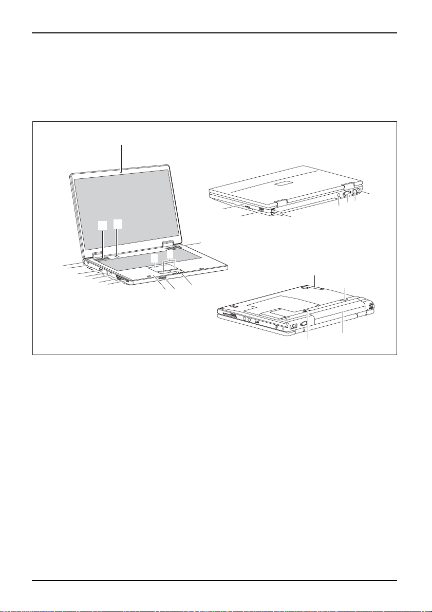
This chapter presents the individual hardw are components. This will provide you with an
overview of the ports and operating elements on the notebook.
Please familiarise yourself with these components before you start to work with your notebook.
StatusindicatorsON/OFFswitchforradiocomponentsMicrophoneExpressCardslotMemorycardslotCameraLoudspeakerON/OFFswitchTouch padTouchpadkeysHeadphonesport/LineOutUSBportDCinputconnector(DC IN)KensingtonLockOpticaldriveMonitorportLANportModemportHarddiskBatteryBatteryrelease latchBatteryreleaseS-Videooutsocket
1
22
21
20
19
23
24
15
14
13
12
11
10
16
3
2
5
4
9
6
7
8
17
2
18
26
1=Camera
2 = Loudspeake r
3 = ON/OFF switch
4 = Touchpad
5 = Touchpad keys
6 = Status indicators
7 = ON/OFF switch for radio components
8 = Microphone
9 = ExpressCard slot
10 = Memory card slot
11 = Headphones port/Line Out
12 = Microphone port/Line In
13 = USB port
4 A26391-K240-Z220-1-7619, edition 1
14 = DC input connector (DC IN)
15 = Kensington Lock
16 = Optical drive
17 = USB port
18 = USB ports
19 = S-Video out socket
20 = Monitor port
21 = LAN port
22 = Modem port
23 = Hard disk
24 = Battery release
25 = Battery
26 = Battery release latch
25
Page 13
Switching on the notebook
2
1
Ports and operating elemen ts
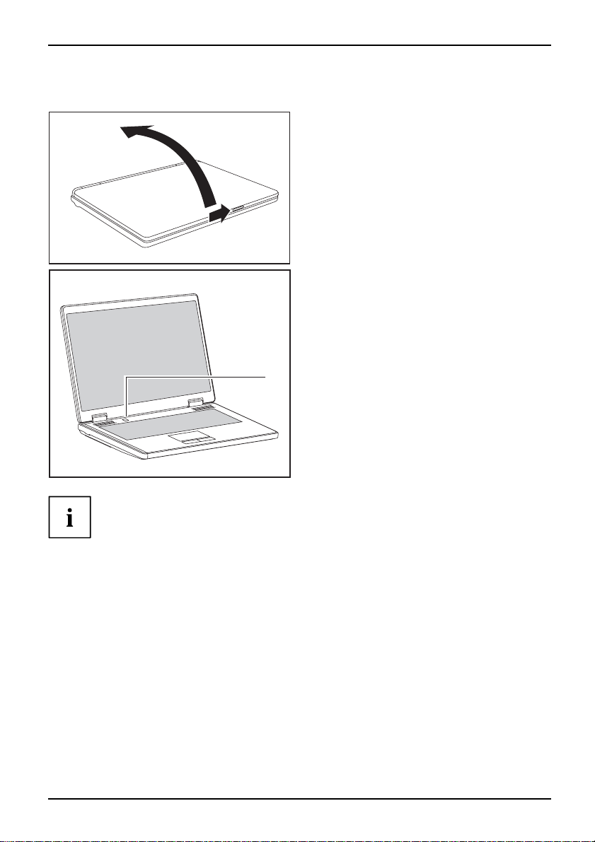
► Slide the release button in direction of the
arrow (1) and open the LCD screen (2).
► Press the ON /OFF switc
the notebook on.
The power-on indicator is lit.
1
Windows XP:
You can configure the power button with Start - (Settings) - Control Panel Performance and Maintenance - Power Options - Advanced.
Windows Vista:
You c an c o nfigure the power button with Start - (Settings) - Control
Panel - Mobile PC - Power Options.
If you have assigned a password, you must enter this when requested to do so, in order
to start the operating system. Further information can be found in the "Professional
Notebook" operating manual, section entitled "Security functions".
h (1) to switch
A26391-K240-Z220-1-7619, edition 1 5
Page 14

Ports and operating elements
Switching off the Notebook
► Close all applications and shut down your operating system (please
see operating system manual).
If the notebook cannot be shut down properly, press and hold the ON/OFF button for
approximately four seconds. The notebook will switch off. Any unsaved data may be lost.
► Close the LCD screen so that it
locks into place.
6 A26391-K240-Z220-1-7619, edition 1
Page 15

Ports and operating elemen ts
A
1
A
1
Status indicators
The status indicators provide information about the status of the powe r supply,
the drives and the keyboard functions.
StatusindicatorsStatusindicators
The meanings of the symbols are as follows:
Radio components indicator
RadiocomponentsRadiocomponents
Indicator lights up: One or more radio components are switched on.
Power indicator
Powerindicator
Indicator lights up: Th
e notebook is switched on.
Energy-saving mode i
Energy-savingmodeEnergy-savingmode
Indicator lights up: Th
Drive indicator
DriveDrive
ndicator
e system is in power-saving mode.
Indicator lights up: One of the drives (e.g. hard disk, CD/DVD) is being accessed.
Battery indicator
BatteryBattery
Indicator lights up: T
Caps Lock indicato
Indicator lights up
type appear in uppe
upper left of the ke
he battery is charging.
r
: The Caps Lock key has been pressed. All the characters you
r case. In the case of overlay keys, the character printed on the
y appears when that key is pressed.
Num Lock indicator
Indicator lights u
p: The key combination
numeric keypa d is a
the upp er right of t
ctivated. In the case of overlay keys, the character printed on
he key appears when that key is pressed.
Fn+Num
A26391-K240-Z220-1-7619, edition 1 7
has been pressed. The
Page 16

Ports and operating elements
Key combinations
The key combinations described below apply when using Microsoft Windows
operating systems. Some of the following key combinations may not function in
other operating systems and with some device drivers.
Key combinations are entered as follows:
► Press and hold the first key in the combination.
► While holding the first key down, press the other key or keys in the combination.
The key combination
Ctrl
Alt Gr
+
or
external keyboards that do not not feature a
Activate/deactivate Wireless LAN, Bluetooth and UMTS (optional)
BluetoothBluetoothUMTSUMTSWLANWLANFn+F1
Use this key combination to start LaunchManager. The radio components that
have been activated in the BIOS Setup can be switched on and off individually.
Fn
The key combination
F1
+
can only be used if the LaunchManager
software is installed on your device.
Switch loudspeakers ON/OFF
Fn+F3Loudspeaker
This key combination switches your notebook’s loudspeakers off and on.
Decrease volume
Fn+F4Volume
This key combination reduces the volume of the integrated loudspeakers.
Increases volume
Fn+F5Volume
This key combination increases the volume of the integrated loudspeakers.
Switch touchpad ON/OFF
This key combination switches your notebook’s touchpad off and on.
d
Fn+F6TouchpadTouchpa
Ctrl+Alt
Fn
key.
canbeusedon
Switch camera ON/OFF
Use this key combination to switch the notebook’s integrated camera on or off.
a
Fn+F7CameraCamer
Decrease screen brightness
Fn+F8Screenbrightness
This key combination decreases the brightness of the screen.
8 A26391-K240-Z220-1-7619, edition 1
Page 17

Ports and operating elemen ts
Increase screen brightness
Fn+F9Screenbrightness
This key combination increases the brightness of the screen.
Toggle output screen
Fn+F10Toggleoutputscreen
Use this key combination to select which screen(s) is/are used for display
if an external monitor is connected.
You can opt to use:
• just the notebook’s L CD screen
• just the external monitor
• both the LCD screen and the external monitor
Sleep mode
ActivateenergysavingmodeFn+F12Sleepmode
Use this key combination to activate the currently configured energy saving
mode.
Switching between open applications
Use this key combination to switch between several open applications.
Alt+Tab
++
SysRq
Del
AltCtrl
Performwarmreboot
This key combination restarts th
both the
Ctrl
and
Alt
keys, then press th
Task Manager will be displayed
again to reboot.
Ctrl+Alt+DelWarmreboot
e notebook. First, press and hold
. You must then press all three keys
Back tab
This key combination moves the cu
stop.
Shift+TabBa cktab
rsor back to the previous tabular
Key combinations using the Windows keys are detailed in the manual
for your operating system.
Del
e
key. First, the
A26391-K240-Z220-1-7619, edition 1 9
Page 18
Ports and operating elements
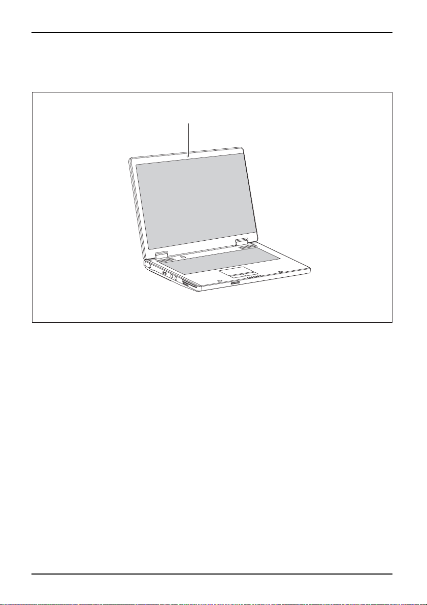
Camera (depending on notebook model)
Your device is fitted with a VGA camera (1), which can also be used as a webcam.
1
10 A26391-K240-Z220-1-7619, edition 1
Page 19

Ports and operating elemen ts
Removing and installing the bat
NotesBattery
tery
Only use batteries approved by Fujitsu PC Asia Pacific Pte Ltd. for y our notebook.
Never use force when inserting or removing a battery.
Make sure that no foreign bodies get into the battery connections.
Removing the battery
► Switch the notebook off and pull the power plug out of the mains socket.
Battery
► Close the LCD screen so that it locks i
nto place.
► Disconnect all cables connected to the notebook.
► Turn your notebook over and place it on
anti-slip cloth on this surface to pre
a stable, sturdy, flat surface. If necessary, lay an
vent the notebook from being scratched.
► Push the battery lock in the direction of
the arrow (1) as far as it will go.
2
1
► Slide the locking device in the dire
the arrow (2) and hold it in place.
► Pull the battery out of the casing in the
direction of the arrow (3).
3
Battery: inserting
► Push the battery into the bat
compartment so that the cont
enter first (1).
Battery
► Push the battery into the battery
2
1
compartment until you feel it click into place.
► Push the battery lock in the d
the arrow (2) up to the stop.
ction of
tery
acts
irection of
A26391-K240-Z220-1-7619, edition 1 11
Page 20

Ports and operating elements
SIM card (optional)
Follow the instructions supplied by the provider of the SIM card.
Inserting the SIM card
► Switch the notebook off and pull the power plug out of t he mains socket.
► Close the LCD screen so that i
► Disconnect all cables connected to the notebook.
► Turn your notebook over and pla
an anti-slip cloth on this sur
► Remove the battery (see Section "
t locks into place.
ce it on a stable, flat and clean surface. If necessary, lay
face to prevent the notebook from being scratched.
Removing the battery", Page 11).
► Insert the SIM c ar d into the s
the the chip is facing upwar
angled corner is at the fron
towards the slot (1). Ensur
the SIM card click into pla
1
lot so that
ds and the
t right, facing
e that you hear
ce.
► Reinstall the battery (see "
► Turn the notebook the right way up and place it on a flat surface.
► Reconnect the cables that you disconnected previously.
12 A26391-K240-Z220-1-7619, edition 1
Battery: inserting", Page 11).
Page 21

Ports and operating elemen ts
Removing a SIM card
► Switch the notebook off and pull the power plug out of the mains socket.
► Close the LCD screen so that it locks into place.
► Disconnect all cables connected to the notebook.
► Turn your notebook over and place it on a stable, flat and clean surface. If necessary, lay
an anti-slip cloth on this surface to prevent the notebook from being scratched.
► Remove the battery (see Section "
1
Removing the battery", Page 11).
► Push the SIM card inw a rds slightly to
eject it from the slot (1).
► Pull the SIM card out of the slot in the
direction of the arrow (2).
2
► Reinstall the battery (see "
► Turn the notebook the right way up and place it on a flat surface.
► Reconnect the cables that you disconnected previously.
Battery: inserting", Page 11).
A26391-K240-Z220-1-7619, edition 1 13
Page 22

Ports and operating elements
Radio components: Wireless LAN/ Bluetooth/UMTS (optional)
WirelessLANBluetoothUMTS
Switching the radio components o n and off
Start the LaunchManager using the ON/OFF switch for the radio components
or the key combination
The LaunchManager enables you to switch the radio components activated in
BIOS Setup on and off individually.
WirelessLANWirelessLANBluetoothBluetoothUMTSUMTS
The installation of a wireless LAN module not approved by Fujitsu PC Asia PacificPte
Ltd. void s the permits issued for this device (see chapter "
Fn
F1
+
.
Technical data", Page 17).
► Slide the ON/OFF switch for the radio
components in the direction of the arrow
to start the LaunchManager.
or
► Press the key combination
to start the LaunchManager.
The radio component indicator will be
illuminated when one or more radio
components is switched on.
Fn+F1
If you switch off the radio components, the Bluetooth module, UMTS and wireless
LAN transmission unit (antenna) will also be switched off.
You can enable or disable the radio components individually.
The BIOS Setup allows you to specify which radio components can be switched on and off
using the ON/OFF switch for the radio components or the key combination
Fn+F1
Only those components that have been activated in the BIOS Setup canbeswitched
on a nd off using the ON/OFF switch for the radio components or the key comb ination
Fn+F1
. Con versely, components that are deactivated in the BIOS setup cannot be
controlled using the ON/OFF switch for radio components or the key combination.
You can also activate and deactivate the radio components individually in the BIOS Setup.
You must have assigned the supervisor password in order for this function to be available.
Pay attention to the additional safety notes for devices with radio
components provided in the "Safety" manual.
Details on using Wireless LAN can be found in the online help system
included in the Wireless LAN software.
You can find more information on how to use Bluetooth on the CD you
received with your Bluetooth software.
You can obtain more information on UMTS from your service provider.
14 A26391-K240-Z220-1-7619, edition 1
.
Page 23

Removing and installing components
during servicing
Removing and installing compo
nents
during servicing
Only qualified technicians should repair your notebook. Unauthorised
opening or incorrect repair may greatly endanger the user (e lectric shock,
fire risk) and will invalidate your warranty.
Servicing
Components
You may remove and install the components described in this chapter yourself
after consulting the Hotline/Help Desk.
If you remove and install components without consulting the Hotline/Help
Desk, then the warranty of your notebook will be voided.
Notes on installing and removing boards and components
• Switch the notebook off and pull the power plug out of the mains socket.
• Remove the battery.
• Take care when you use the locking mechanisms on the battery and any other component.
• Never use sharp objects suc
NotesBoa rdESD
Boards with electrostatic sensitive devices (ESD) are marked with the label
shown.
When handling boards fitted with ESDs, you must always observe the following
points:
• You must always discharge static build up (e.g. by touching a grounded
object) before working.
• The equipment and tools you use must be free of static charges.
• Remove the power plug from the mains supply before inserting or removing
boards containing ESDs.
• Always hold boards with ESDs by their edges.
• Never t ouch pins or conductors on boards fitted with ESDs.
h as screwdrivers, scissors or knives as leverage to remove covers.
A26391-K240-Z220-1-7619, edition 1 15
Page 24

Removing and installing components
during servicing
Hard disk
The hard disk is the most important storage medium of your notebook. You can work considerably
faster and more efficiently if you copy applications and files from CDs to your hard disk.
When the hard disk is accessed, the hard disk indicator lights up in the status indicator panel.
Removing the hard disk
► Switch the notebook off and pull the power plug out of t he mains socket.
Harddisk
► Close the LCD screen so that it locks into place.
► Disconnect all cables connected to the notebook.
► Turn your notebook over and place it on a stable, sturdy, flat surface. If necessary, lay an
anti-slip cloth on this surface to prevent the noteb ook from being scratched.
► Remove the battery (see "
1
Removing the battery", Page 11).
2
1
3
► Remove the screws (1).
► Lift off the cover (2).
► Pull the hard disk out of the bay in the
direction of the arrow (3).
Installing the hard disk
► Pushtheharddiskintotheharddisk
3
► Install the battery again (see "
► Turn the notebook the right way up and place it on a flat surface.
► Reconnect the cables that you disconnected previously.
16 A26391-K240-Z220-1-7619, edition 1
2
3
1
Battery: inserting", Pa ge 11).
bay (1) in a straight line.
► Position the cover (2).
► Secure the cover with the screws (3 ).
Page 25

Technical data
Notebook
Technicaldata
Environmental conditions
Environmental class 3K2
Temperature
Operating (3K2) 5°C – 35°C
Transport (2K2) -15 °C – 60 °C
Dimensions
Width x Depth x Height (front/back)
Weight (depending on configuration)
364 mm x 259 mm x 24–37 mm
Approx. 2.8 kg
Technical data
The data sheet of this notebook contains further technical data. You can find
the data sheet on your notebook, on our website "
or on the "Drivers & Utilities" CD/DVD.
www.pc-ap.fujitsu.com"
Battery
Technicaldata
Rated voltage
Rated capacity
The operating time depends on the device equipment, the active
applications and the energy saving s ettings.
3-cell rechargeable battery 6-cell rechargeable battery
10.8 V / 11.1 V 10.8 V / 11.1 V
depends on configuration depends on configuration
Mains adapter
ldataforthe
Technic a
Electrical data
Rated voltage 20 V
Max. rated c urrent 4.5 A
An additional mains adapter and power cable can be ordered at any time.
A26391-K240-Z220-1-7619, edition 1 17
Page 26

Index
Index
A
Activate energy saving mode 9
Alt+Tab 9
B
Back tab 9
Battery 4
important notes 11
indicator 7
inserting 11
removing 11
Battery release 4
Battery release latch 4
Bluetooth 14
switching off 8, 14
switching on 8, 14
Board 15
C
Camera 4
switching off 8
switching on 8
Components
installing / removing 15
Ctrl+Alt+Del 9
D
DC input connector (DC IN) 4
Drive
indicator 7
E
Energy-saving mode
indicator 7
ESD 15
ExpressCard slot 4
H
Hard disk 4
removing 16
Headphones port/Line Out 4
K
Kensington Lock 4
L
LAN port 4
Loudspeaker 4
switching ON/OFF 8
M
Memory card slot 4
Microphone 4
Modem port 4
Monitor port 4
N
Notes
battery 11
boards 15
O
ON/OFF switch 4
ON/OFF switch for radio components 4
Optical drive 4
P
Power indicator 7
R
Radio components
indicator 7
F
Fn + F1 8
Fn + F10 9
Fn + F12 9
Fn + F3 8
Fn + F4 8
Fn + F5 8
Fn + F6 8
Fn + F7 8
Fn + F8 8
Fn + F9 9
18 A26391-K240-Z220-1-7619, edition 1
S
S-Video out socket 4
Screen brightness
decrease 8
increase 9
Servicing 15
Shift+Tab 9
Sleep mode
activating 9
Status indicators 4, 7
Page 27

Index
T
Technical data
battery 17
Notebook 17
Technical data for the
mains adapter 17
Toggle output screen 9
Touchpad 4
switching off 8
switching on 8
Touchpa d keys 4
U
UMTS 14
switching off 8, 14
switching on 8, 14
USB port 4
V
Volume
decrease 8
increase 8
W
Warm reboot 9
Wireless LAN 14
switching off 14
switching on 14
WLAN
switching off 8
switching on 8
A26391-K240-Z220-1-7619, edition 1 19
 Loading...