

Page 1

IP-900 Series
SOFTWARE
V01
USER’S GUIDE
C134-E016-03
Page 2

USING IP-900 Series SAFELY
Handling of This Manual
This manual contains important information regarding the safe use of IP-900 series. Before
attempting to use this product, read this document thoroughly, paying particular attention to the "Notes
on Safety." Be sure to keep this document in a safe and convenient location for quick reference.
Fujitsu makes every effort to prevent users and bystanders from being injured and to prevent
property damage. Be sure to use this product in accordance with the instructions in this manual.
Warning on Electromagnetic Interference
The following notice is for USA users only.
IP-900 series has been tested and found to comply with the limits for a Class A digital device, pursuant
to Part 15 of the FCC Regulations. These limits are designed to provide reasonable protection against
harmful interference when the equipment is operated in a commercial environment. This equipment
generates, uses and can radiate radio frequency energy, and if not installed and used in accordance with
the instruction document, may cause harmful interference to radio communications. Operation of this
equipment in a residential area is likely to cause harmful interference in which case the user will be
required to correct the interference at his own expense.
The following notice is for Canada users only.
This Class A digital apparatus meets all requirements of the Canadian Interference-Causing
Equipment Regulations.
The following notice is for EU (European Union) use rs only.
This is Class A product of Electromagnetic Interference (EMI) standard. In a domestic environment
this product may cause radio interference in which case the user may be required to make adequate
measures.
This manual contains technology controlled by Foreign Exchange and Foreign Trade Law. This
document or a portion thereof must not be exported (or re-exported) from Japan without authorization
from the appropriate Japanese governmental authorities in accordance with such laws.
It is strictly inhibited to copy or reverse-engineer (reverse-assemble or reverse-compile) any programs
included in the relevant equipment.
Microsoft, Windows, Windows NT, Windows 2000, and Windows XP are trademarks or registered
trademarks of Microsoft Corporation in the United States and other countries.
- The contents of this document shall not be disclosed in any way or reproduced in any media without
the express written permission of Fujitsu Limited.
©
All Rights Reserved, Copyright
FUJITSU LIMITED 2008 -2009
IP-900 Series
II
Page 3

PREFACE
This document explains how to use software for IP-900 series.
For information on how to install IP-900 series, connect cables and use buttons and LEDs, see the
following manual:
- IP-900 Series User's Guide
This document is intended for system designers or administrators who use IP-900 series. It assumes that
these users have a basic understanding of networks and video streaming.
Edition 03
Nov 2009
Product Use Environment
The product explained in this document is designed and manufactured for use in standard applications
such as general office work, personal devices and household appliances. This product has not been
designed or manufactured for special uses requiring extremely high levels of safety, or if the required
level of safety cannot be ensured, for uses where a failure, operational error or some other factor could
be life-threatening or cause a physical injury (such as nuclear-reactor control in atomic facilities,
automatic flight control, air traffic control, mass transportation control, medical devices for life support,
or missile launch controls in weapons facilities). (In this document, these special uses are referred to as
"high-risk" uses.) The customer is urged not to use this product without taking measures to guarantee
the level of safety required for such high-risk uses. Customers that are likely to use this product for
high-risk applications are requested to consult our sales representative before embarking on such
specialized use.
Note
The contents of this manual may be revised without prior notice.
III
IP-900 Series
Page 4

ALERT INDICATIONS
This document uses various alert indications to urge the user to use the equipment safely, to prevent
users and bystanders from suffering personal injury or property damage. Alert indication consists of
alert signal and alert statement. The alert signals and their meanings are as follows.
This indicates a hazardous situation that could result in death or serious
personal injury if you do not perform the procedure correctly.
This indicates a hazardous situation that could result in minor or moderate
personal injury if the user does not perform the procedure correctly. This
signal also indicates that damage to the product or other property may occur
if the user does not perform the procedure correctly.
Alert Indication in This Manual
An alert statement follows an alert signal. An alert signal is provided in the center of a line. An alert
statement is indented on both ends to distinguish it from regular text. Similarly, one space line is
inserted before and after the alert statement.
(Example)
Electric shock
Consult the system administrator when checking the voltage at the outlet.
Otherwise, electric shock may result.
IP-900 Series
IV
Page 5

NOTE ON HANDLING THE PRODUCT
Maintenance
Users must not attempt to repair IP-900 series themselves. Consult the Fujitsu Service Center.
Read this document thoroughly before using the product. For clarification of any unclear points
regarding the use of the product, consult the Fujitsu Service Center.
If a fault occurs, contact the Fujitsu Service Center with information on the fault and the alarm LED
status.
V
IP-900 Series
Page 6

CONTENTS
USING IP-900 series SAFELY.......................................................................II
PREFACE.....................................................................................................III
ALERT INDICATIONS.................................................................................. IV
NOTE ON HANDLING THE PRODUCT....................................................... V
Chapter 1 Before Using This Product .............................................2
1.1 Main Features.......................................................................................3
1.2 Typical Application Examples................................................................8
Chapter 2 Installation & Operation...................................................9
2.1 Updating the Software ........................................................................10
2.1.1 Installation Procedure.................................................................10
2.1.2 Installing an Upgrade License.....................................................12
2.2 Equipment Operation..........................................................................15
2.2.1 Operation through Web Screen..................................................15
2.2.2 Notes ..........................................................................................15
Chapter 3 Web Operation................................................................17
3.1 Starting Up..........................................................................................18
3.1.1 Login...........................................................................................18
3.1.2 If the Screen is Not Accessible ...................................................21
3.2 Common Menu ...................................................................................22
3.2.1 Configuration Data......................................................................22
3.2.2 Selecting Configuration Data......................................................24
3.2.3 Copying Configuration Data........................................................29
3.2.4 Basic...........................................................................................31
3.2.5 Time Zone & Time Server...........................................................34
3.2.6 Data Port.....................................................................................36
3.2.7 SNMP .........................................................................................39
3.2.8 Operation & Status (Common)....................................................41
3.2.9 Alarm...........................................................................................44
3.2.10 Log............................................................................................48
3.2.11 Performance Statistics ..............................................................55
3.2.12 Date & Time.............................................................................. 62
3.2.13 Software Management..............................................................63
3.2.14 Reboot......................................................................................65
3.3 Encoder ..............................................................................................66
3.3.1 Setting (Encoder)........................................................................66
3.3.2 Encoder Address Report.............................................................85
3.3.3 Superimpose...............................................................................88
3.3.4 Operation & Status (Encoder).....................................................91
3.4 Recorder.............................................................................................93
Page 7

3.4.1 Setting (Recorder)...................................................................... 93
3.4.2 File List....................................................................................... 95
3.4.3 Operation & Status (Recorder)................................................... 97
3.5 Decoder.............................................................................................. 99
3.5.1 Setting (Decoder)....................................................................... 99
3.5.2 Encoder Selection.................................................................... 103
3.5.3 Operation & Status (Decoder).................................................. 105
Chapter 4 Troubleshooting........................................................... 107
4.1 Troubleshooting................................................................................ 108
4.2 Alarm LED Goes On..........................................................................111
Appendixes..................................................................................... 119
Glossary.................................................................................................... 120
Index ......................................................................................................... 129
Page 8

Chapter 1 Before Using This Product
Chapter 1 Before Using This Product
Before Using This Product
Chapter 1
This chapter explains items to be confirmed before using IP-900 series.
1.1 Main Features.......................................................................................3
1.2 Typical Application Examples................................................................8
IP-900 Series
2
Page 9

Chapter 1 Before Using This Product
1.1 Main Features
1.1
IP-900 series is a video encoder that uses the high compression video encoding technology H.264. It
enables real-time streaming of high definition (HD) and standard definition (SD) video through the
optical fiber networks like FTTH.
The IP-900E can operate as an encoder and the IP-900D/IP-900IID can operate as a decoder. When
operating as an encoder, the IP-900E encodes input video and audio signals into the H.264 format and
distributes the results over an IP network in real-time processing. When operating as a decoder, the
IP-900D/IP-900IID decodes encoded data received over an IP network and outputs the results as audio
and video signals. In addition, the IP-900E operating as an encoder provides a recorder function (*1),
which allows HD video data to be transmitted over a longer period of time even when the network
bandwidth is low.
IP-900E encoder also features simulcast (dual encoding) capability to distribute two kinds of the
encoded streams that are produced from a single video input by main and sub encoder of IP-900E in
real-time.
Table 1-1 IP-900E Specifications
The main HD video and sub HD video functions become available when the HD option is added.
Item Specification
Main HD
video
Main SD
video
Encoding format H.264 HP@L4
H.264 MP@L4
Input video format 1920 x 1080i (59.94 Hz)
1920 x 1080i (50 Hz)
1920 x 1080i (60 Hz)
1280 x 720p (59.94 Hz)
1280 x 720p (50 Hz)
* Video input protection buffer OFF/ON can be specified.
Bit rate 1920 x 1080: 4 to 27 Mbps
1440 x 1080: 4 to 27 Mbps
960 x 1080: 1 to 27 Mbps
1280 x 720: 4 to 27 Mbps
960 x 720: 4 to 27 Mbps
640 x 720: 1 to 27 Mbps
Video PES “1Field/1PES” / “1Frame/1PES” selectable
Profile selection Either High profile or Main profile can be selected.
PPS interval GOP/Picture selectable
PPS ID Fixed/Adaptive selectable
Encoding control
mode
Pre-filter HEAVY, MEDIUM, LIGHT, or OFF can be selected.
Refresh cycle Selection can be made in three stages.
Interfaces Input: HD-SDI and HDMI (HDCP not supported)
Encoding format H.264 HP@L3
Standard (IBBP), Low latency (IPPP), or Low latency (PPPP) can be selected.
H.264 MP@L3
3
IP-900 Series
Page 10

Chapter 1 Before Using This Product
Item Specification
Input video format 720 x 480i (59.94 Hz)
720 x 576i (50 Hz)
* Video input protection buffer OFF/ON can be specified.
Bit rate 720 x 480: 1 to 10 Mbps
352 x 480: 500Kbps to 10Mbps
720 x 576: 1 to 10 Mbps
352 x 576: 500Kbps to 10Mbps
Video PES “1Field/1PES” / “1Frame/1PES” selectable
Profile selection Either High profile or Main profile can be selected.
PPS interval GOP/Picture selectable
PPS ID Fixed/Adaptive selectable
Encoding control
Standard (IBBP), Low latency (IPPP), or Low latency (PPPP) can be selected.
mode
Pre-filter HEAVY, MEDIUM, LIGHT, or OFF can be selected.
Refresh cycle Selection can be made in three stages.
Interfaces Input: SD-SDI, HDMI (HDCP not supported), and analog video
Sub HD
video
Encoding format H.264 HP@L4
H.264 MP@L4
Input video format 1920 x 1080i (59.94 Hz)
1920 x 1080i (50 Hz)
1920 x 1080i (60 Hz)
1280 x 720p (59.94 Hz)
1280 x 720p (50 Hz)
* Video input protection buffer OFF/ON can be specified.
Bit rate 1920 x 1080: 4 to 27 Mbps
1440 x 1080: 4 to 27 Mbps
960 x 1080: 1 to 27 Mbps
1280 x 720: 4 to 27 Mbps
960 x 720: 4 to 27 Mbps
640 x 720: 1 to 27 Mbps
Video PES “1Field/1PES” / “1Frame/1PES” selectable
Profile selection Either High profile or Main profile can be selected.
PPS interval GOP/Picture selectable
PPS ID Fixed/Adaptive selectable
Encoding control
Standard (IBBP), Low latency (IPPP), or Low latency (PPPP) can be selected.
mode
Pre-filter HEAVY, MEDIUM, LIGHT, or OFF can be selected.
Refresh cycle Selection can be made in three stages.
Interfaces Input: HD-SDI and HDMI (HDCP not supported)
Sub SD
video
Encoding format H.264 HP@L3
H.264 MP@L3
H.264 MP@L1.3
Input video format 1920 x 1080i (59.94Hz)
1920 x 1080i (50Hz)
1280 x 720p (59.94Hz)
1280 x 720p (50Hz)
720 x 480i (59.94Hz)
720 x 576i (50Hz)
IP-900 Series
4
Page 11

Chapter 1 Before Using This Product
Item Specification
Bit rate
Video PES “1Field/1PES” / “1Frame/1PES” selectable
720 x 480 (59.94Hz input): 1 to 10Mbps
352 x 480 (59.94Hz input): 500Kbps to 10Mbps
352 x 240 (59.94Hz input): 50 to 512Kbps
176 x 112 (59.94Hz input): 25 to 50Kbps
720 x 576 (50Hz input): 1 to 10Mbps
352 x 576 (50Hz input): 500Kbps to 10Mbps
352 x 288 (50Hz input): 50 to 512Kbps
176 x 144 (50Hz input): 25 to 50Kbps
Encoding control
Pre-filter HEAVY, MEDIUM, LIGHT, or OFF can be selected.
Refresh cycle Selection can be made in three stages.
Interfaces Input: HD/SD-SDI, HDMI (HDCP not supported), and analog video
Main
audio
Number of
Interfaces Input: HD/SD-SDI (embedded) - Up to 2 channels
Sub audio
Profile selection Either High profile or Main profile can be selected.
PPS interval GOP/Picture selectable
PPS ID Fixed/Adaptive selectable
Standard (IBBP), Low latency (IPPP), or Low latency (PPPP) can be selected.
mode
Encoding format MPEG-1 Audio layer 2 (stereo)
Sampling
frequency
Bit rate (for 2
channels)
channels
Encoding format MPEG-1 Audio layer 2 (stereo)
* Can be selected when the encoding resolution is 720 x 480, 720 x 576, 352 x
480, or 352 x 576.
* Can be selected when the encoding resolution is 720 x 480, 720 x 576, 352 x
480, or 352 x 576.
* Can be selected when the encoding resolution is 720 x 480, 720 x 576, 352 x
480, or 352 x 576.
MPEG-2 AAC (stereo)
48 kHz
MPEG-1 Audio layer 2: 128/256/384 kbps
MPEG-2 AAC: 64/128/256 kbps
2
HDMI - Up to 2 channels
Analog (unbalanced): - Up to 2 channels
Output: None
MPEG-2 AAC (stereo)
Sampling
frequency
Bit rate (for 2
channels)
Number of
channels
Interfaces Input: HD/SD-SDI (embedded) - Up to 2 channels
Multiplexing method MPEG-2 TS with time stamp, MPEG-2 TS
Error correction FEC, ARQ, Pro-MPEG FEC
Transport protocol UDP, RTP
Network interface 10 BASE-T/100 BASE-TX (PPPoE built in)
48 kHz
MPEG-1 Audio layer 2: 128/256/384 kbps
MPEG-2 AAC: 64/128/256 kbps
2
HDMI - Up to 2 channels
Analog (unbalanced) - Up to 2 channels
Output: None
1 port
5
IP-900 Series
Page 12

Chapter 1 Before Using This Product
Item Specification
Network time setting SNTP client
Network management SNMP agent
Data communication RS-232C data communication
Superimpose Superimpose up to four character string or time indication into input video
Local recording and file
transfer (*1)
Supported CF cards: 4-GB, 8-GB and 16-GB cards
* Recording can be performed with a system rate of 14 Mbps or less. Recording
and acquisition can be performed simultaneously for the system rate of 6
Mbps or less.
*1: CF cards are separately sold options.
IP-900 Series
6
Page 13

Chapter 1 Before Using This Product
Table 1-2 IP-900D/IP-900IID Specifications
Item Specification
Video
decoding
Interfaces Output: HD/SD-SDI (IP-900IID), HDMI (HDCP not supported) and
Audio
decoding
Number of channels 2
Interfaces Output: HDMI - Up to 2 channels
Multiplexing method MPEG-2 TS with time stamp, MPEG-2 TS,
Error correction FEC, ARQ, Pro-MPEG FEC
Transport protocol UDP, RTP
Network interface 10 BASE-T/100 BASE-TX (PPPoE built in)
Network time setting SNTP client
Network management SNMP agent
Data communication RS-232C data communication
Encoding format H.264 HP@L4
H.264 MP@L4
H.264 HP@L3
H.264 MP@L3
H.264 MP@L1.3
MPEG-2 MP@ML (IP-700II stream reception)
Output video format 1920 x 1080i (59.94Hz)
1920 x 1080i (50 Hz)
1920 x 1080i (60 Hz)
1280 x 720p (59.94 Hz)
1280 x 720p (50 Hz)
720 x 480i (59.94 Hz)
720 x 576i (50 Hz)
Bit rate 1920 x 1080: 4-27Mbps
1440 x 1080: 4-27Mbps
960 x 1080: 1-27Mbps
1280 x 720: 4-27Mbps
960 x 720: 4-27Mbps
640 x 720: 1-27Mbps
720 x 480: 1-10Mbps
352 x 480: 500Kbps-10Mbps
352 x 240: 50-512Kbps
720 x 576: 1-10Mbps
352 x 576: 500Kbps-10Mbps
352 x 288: 50-512Kbps
176 x 112: 25-50Kbps
176 x 144: 25-50Kbps
analog
Encoding format MPEG-1 Audio layer 2 (stereo)
MPEG-2 AAC (stereo)
Sampling frequency 48 kHz
Bit rate (for 2 channels) MPEG-1 Audio layer 2: 128/256/384 kbps
MPEG-2 AAC: 64/128/256 kbps
Analog (unbalanced) - Up to 2 channels
MPEG-2 PS (IP-700II stream reception)
1 port
7
IP-900 Series
Page 14

Chapter 1 Before Using This Product
1.2 T ypical Application Examples
1.2
This section provides system configuration examples.
The basic configuration is for video transfer via point-to-point connections. With this configuration, a
camera is connected to the encoder, and video data is transferred to the decoder over the Internet, and then
output to the monitor.
SDI, etc.
IP-900E
Internet
Live
distribution
IP-900D/IP-900IID
Camera
HDMI, etc.
Monitor
Figure 1-1 System configuration example: Broadcast materials transfer and live
relays
Just like the IP-9500, the IP-900E can also be used to relay images through video transmission from
the IP-900E to an IP-9500D.
Live
distribution
Camera
SDI
IP-900E
IP
Outdoor broadcast
vehicle, etc.
DVB-ASI
Satellite
facilities
IP-9500D
HD-SDI
Broadcast
equipment
Figure 1-2 System configuration example: SNG
IP-900 Series
8
Page 15

Chapter 2
Chapter 2 Installation & Operation
Installation & Operation
This chapter explains how to install IP-900 series.
2.1 Updating the Software........................................................................ 10
2.2 Equipment Operation ......................................................................... 15
Page 16
Chapter 2 Installation & Operation
2.1 Updating the Software
2.1
This section explains the procedure for updating the software for the IP-900 series as well as the
procedure for applying for an HD option license.
The software for the IP-900 series is pre-installed at product shipment. For this reason, you do not need
to install the software before using the IP-900 series. When updating the software to the latest version,
use the following procedure.
2.1.1 Installation Procedure
(1) Access method
Access IP-900 series Web page from the Web browser.
The default IP address of the IP-900 series as it is shipped from the factory is 10.0.0.1.
Temporarily disable the proxy setting on your Web browser and then type "http://10.0.0.1" to
access the Web page.
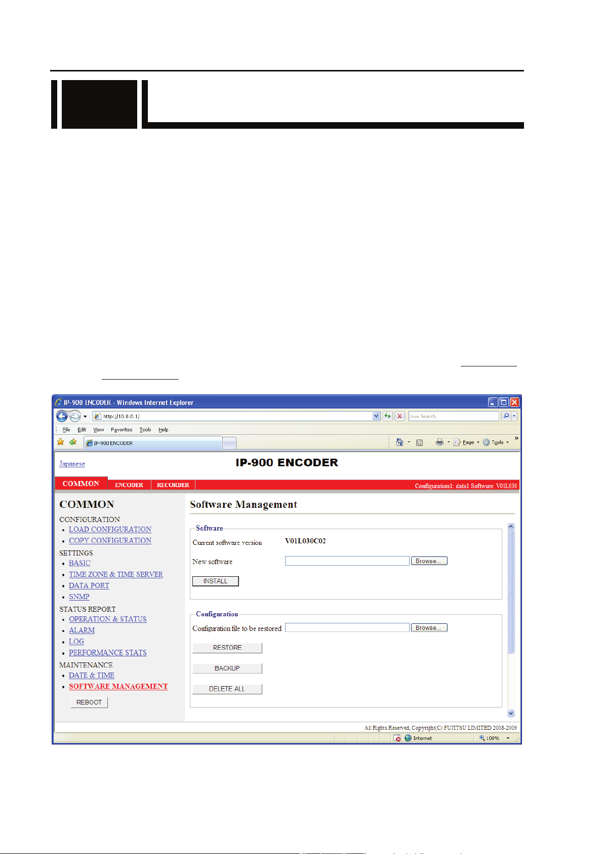
(2) Installation page
IP-900 ENCODER or IP-900 DECODER screen appears. Click SOFTWARE
MANAGEMENT in the left frame of the Web browser screen. The Software management
window (installation, etc.) appears in the right frame of the Web browser screen.
IP-900 Series
Figure 2-1 Installation Window
10
Page 17
Chapter 2 Installation & Operation
(3) Selecting software
Select installation file field. Select the file of the firmware to be updated.
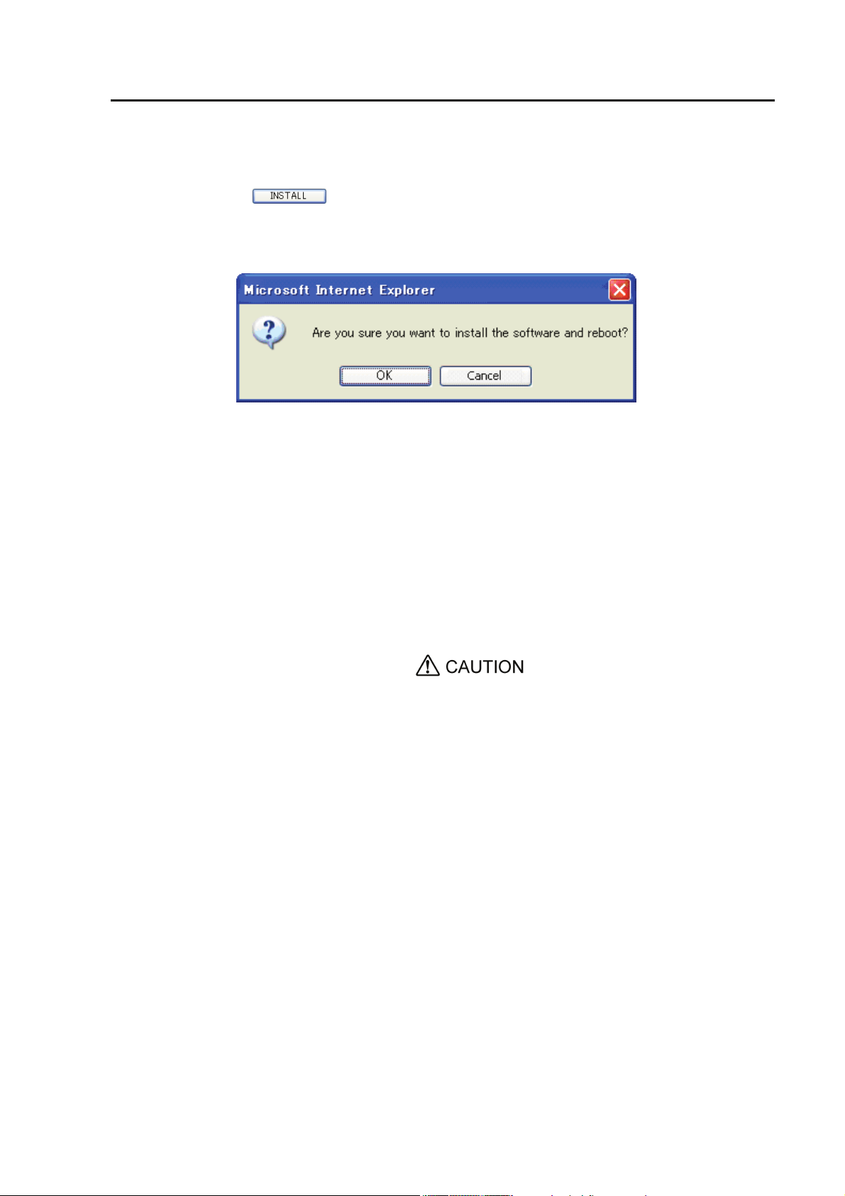
(4) Starting installation
Click the
button. The following confirmation dialog box appears. Click the OK
button to start installation. Upon completion of installation, IP-900 series is automatically
rebooted.
* If the version of the firmware that to be installed is earlier than the one that is currently
installed on the IP-900 series, you can install it in the maintenance mode of the device. The
device can be booted as maintenance mode by pushing MNT button, and then the device is
initialized. Click the OK button to start the installation process if initialization will raise no
problems.
(5) Verifying the startup
Display the IP-900 series setup window from the Web browser, and verify that the new
software has been installed and started.
Do not power off or press the MNT button during installation. Doing so may prevent IP-900 series
from starting.
Do not access another Web page during installation. Otherwise, you may lose information on the
progress.
11
IP-900 Series
Page 18
Chapter 2 Installation & Operation
2.1.2 Installing an HD Option License
In the IP-900 series, you can upgrade the device functions by purchasing an HD option license and
installing it on the main unit.
(1) Applying for an installation key
If you have purchased an HD option license separately from the IP-900 series, you need to
apply for an installation key to enable the function upgrade.
To apply for an installation key, enter the necessary information in the application form
"HDOP_LicenseRequestSheet.txt," which is included in the top directory on this document
CD-ROM, and send the form by e-mail to tnb3-ip9@ml.css.fujitsu.com .
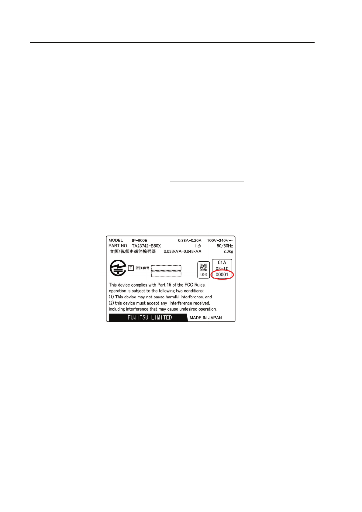
When sending the file, you must specify the device serial number of the IP-900 series on which
you want to install the upgrade function. You can obtain the device serial number from the label
attached to the bottom of the IP-900 series or from the device serial number field on the
[Common] - [Operation & Status] page of the IP-900 series configuration Web page.
IP-900 Series
Figure 2-2 Label at the bottom of the IP-900E (example)
12
Page 19

Chapter 2 Installation & Operation
Figure 2-3 IP-900 series Web page (example)
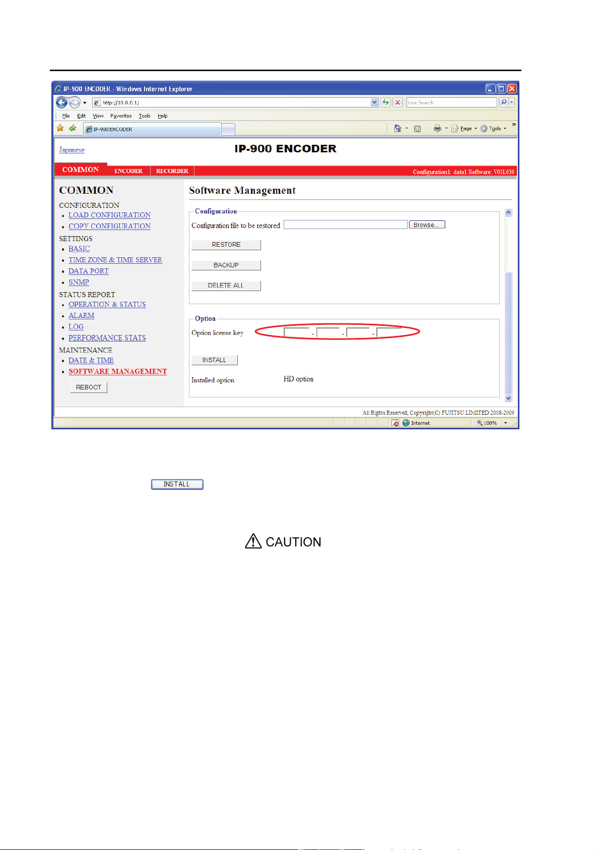
(2) Entering the option license key
Enter the installation license key you have obtained with the application procedure.
Connect to the IP-900 series using a Web browser, and then click [Install] in the left frame of the
Web page. The right frame displays the installation page (for installation and related operations).
In the option license field, enter the installation key obtained in Step (1) above.
13
IP-900 Series
Page 20
Chapter 2 Installation & Operation
Figure 2-4 Option License Installation
(3) Starting installation
Click the
OK button to start installation.
Do not turn off the power or press the MNT button during installation. Doing so may make the
IP-900 series fail to start.
Do not access another Web page during installation. Otherwise, you may lose the installation
progress information.
button. The confirmation dialog box shown above appears. Click the
IP-900 Series
14
Page 21

Chapter 2 Installation & Operation
2.2 Equipment Operation
2.2
This section explains how to operate IP-900 series Software.
The Software can be operated through the Web screen or the front panel.
2.2.1 Operation through Web Screen
All IP-900 series settings and status information can be checked through the Web screen. See Chapter
3, “Web Operation,” for more information.
2.2.2 Notes
◆In the case of failure in automatic acquisition of an IP address
When IP-900 series starts, the LAN port:
(1) Cannot access the DHCP server
(2) Attempts to but fails to set up a PPPoE connection.
If the conditions in (1) and (2) above are met, all 0s (zero) are displayed and IP address
acquisition is repeated.
Take proper corrective action such as reviewing the settings on the DHCP and PPPoE servers or
the IP address setting on IP-900 series. (See also Section 5.1, “Troubleshooting.”)
◆Forcibly changing to the fixed IP address from DHCP, PPPoE
Start the IP-900 series by turning on the power while holding down the MNT button (for about 10
seconds) until the RDY LED lamp starts blinking in orange. For this startup, the IP address and
subnet mask are assumed temporarily restored to the settings at shipment from the factory (LAN
port with an IP address of 10.0.0.1 and a subnet mask of 255.0.0.0).
Use this method to make the IP-900 series initial settings from a PC (*).
* When running the IP-900 series product with the default IP address, ensure that it is disconnected
from your network.
After configuring the settings as suitable for your network, connect the product to your network.
Having the product is connected to your network while the default settings are left unchanged may
cause unexpected problems on your network.
If you started the product while holding down the MNT button, set the IP address and subnet
mask of the PC as follows:
- LAN port IP address: 10.aaa.bbb.ccc
(aaa and bbb can be any number from 0 to 255 and ccc can be any number from 2 to 255.
Note, however, that the resulting address must be other than 10.255.255.255.)
- LAN port subnet mask: 255.0.0.0
15
IP-900 Series
Page 22

Chapter 2 Installation & Operation
◆Powering off on PPPoE connection
If you turn off the power to the IP-900 series while it is connected via PPPoE-connection, the
IP-900 series may take extra time to establish the next connection depending on the network
conditions. To prevent this, use the following procedure to turn off the power to the IP-900 series
to ensure that the PPPoE termination procedure is performed.
Hold down the MNT button for three seconds. When the software finishes termination
processing and the product becomes ready for power-off, the RDY LED goes off.
After verifying that the RDY LED has gone off, turn the power switch to the "{" position. The
PWR LED goes off, indicating that the power is turned off.
IP-900 Series
16
Page 23

Chapter 3 Web Operation
Chapter 3
Chapter 3 Web Operation
Web Operation
This chapter explains how to operate individual functions from the Web
browser.
3.1 Starting Up ......................................................................................... 18
3.2 Common Menu................................................................................... 22
3.3 Encoder.............................................................................................. 66
3.4 Recorder ............................................................................................ 93
3.5 Decoder.............................................................................................. 99
Note: For information on the IP-900E, see Section 3.1,
"Starting Up," Section 3.2, "Common Menu," Section 3.3,
"Encoder," and Section 3.4, "Recorder." For information on the
IP-900D/IP-900IID, see Section 3.1, "Starting Up," Section 3.2,
"Common Menu," and Section 3.5, "Decoder."
17
IP-900 Series
Page 24

Chapter 3 Web Operation
3.1 Starting Up
3.1
3.1.1 Login
By default, the network password window shown below is invalid (not displayed).
To enable the network password function, set the user name and password by following the
instructions in Section 3.2.4, “Basic.”
From the upper part of the Web screen, select [COMMON], [ENCODER], [DECODER] and
[RECORDER] to display these menus.
Ⓡ
* Microsoft
Internet Explore 6.0 SP2 is the recommended Web browser.
IP-900 Series
18
Page 25
Chapter 3 Web Operation
Figure 3-1 IP-900E Software Window Example
19
IP-900 Series
Page 26
Chapter 3 Web Operation
Figure 3-2 IP-900D/IP-900IID Software Window Example
IP-900 Series
20
Page 27

Chapter 3 Web Operation
3.1.2 If the Screen is Not Accessible
For some time after the power-on or reboot, you may not be able to access the screen normally.
Please wait for about 60 seconds before starting access.
21
IP-900 Series
Page 28

Chapter 3 Web Operation
3.2 Common Menu
3.2
3.2.1 Configuration Data
In the IP-900 series terminology, the set of parameters required for operation is called "configuration
data." IP-900 series has a data storage area in which up to 10 sets of configuration data can be stored.
By storing up to 10 sets of configuration data in advance in the storage area, it can be used by
switching with ease between these sets of configuration data.
For instance, it is useful in switching between encoder and decoder, changing resolution or bit rates
or switching the network interfaces including PPPoE, DHCP, static IP, etc.
To easily register these 10 sets of configuration data, you can use the procedures explained in Section
3.2.2, "Selecting Configuration Data," and Section 3.2.3, "Copying Configuration Data."
Table 3-1 Parameters Preprogrammed in Configuration Data lists the parameters, of which 10
sets can be stored independently as configuration data. For detail information on the individual
parameters, see the respective sections shown in the reference column in the table below.
Table 3-1 Parameters Preprogrammed in Configuration Data
Category Window Name Group Name Reference
COMMON BASIC Ethernet common setting 3.2.4 Basic
IPv4 network settings
IPv6 network settings
Other settings
Time zone setting TIME ZONE &
TIME SERVER
DATA PORT Operation settings 3.2.6 Data Port
Port number settings
RS-232C settings
SNMP Operation settings 3.2.7 SNMP
ENCODER SETTINGS AV input settings (Video) 3.3.1 Setting (Encoder)
AV input settings (Audio)
Output interface settings
Output interface settings
Output interface settings
Output interface settings
Main encoder settings
Sub encoder settings
Time server settings
(Main encoder ethernet)
(Main encoder ethernet port)
(Sub encoder ethernet)
(Sub encoder ethernet port)
(Encode)
(Encode)
3.2.5 Time Zone & Time Server
IP-900 Series
22
Page 29

Chapter 3 Web Operation
Category Window Name Group Name Reference
ENCODER
ADDRESS
REPORT
SUPERIMPOSE Main/Sub encoder
RECORDER SETTINGS Recorder settings 3.4.1 Setting (Recorder)
DECODER SETTINGS Input interface settings
Input interface settings
AV output setting (Video)
Decoder settings (Decode)
Main/Sub Report settings
Main/Sub Destination
settings
superimpose settings
(Decoder ethernet)
(Decoder ethernet port)
3.3.2 Encoder Address Report
3.3.3 Superimpose
3.5.1 Setting (decoder)
23
IP-900 Series
Page 30
Chapter 3 Web Operation
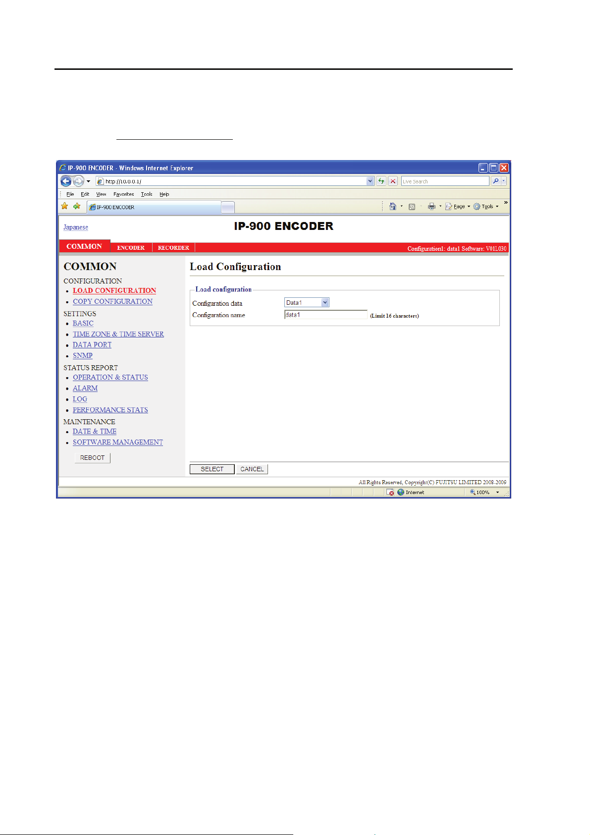
3.2.2 Selecting Configuration Data
Click LOAD CONFIGURATION
data window in the right frame.
in the left frame of the Web screen to display the Configuration
IP-900 Series
Figure 3-3 Configuration Data Window
24
Page 31

Chapter 3 Web Operation
◆Registering configuration data
Select data numbers 1 to 10 from the drop-down list menu in the configuration data field.
Figure 3-4 Selecting Configuration Data
Assign the selected data a name using up to 16 alphanumeric characters in the Configuration
name field, and then click the
button to change the registration number of the configuration data.
*) Reboot is required only when the operation mode is changed between encoder and decoder after
loading configuration.
Confirm that the configuration data number in the upper right red zone on the Basic setting
window has been changed to the previously selected number.
Configuration1: data1 Software: VxxLxxx
button. The dialog box shown below appears. Click the OK
25
IP-900 Series
Page 32

Chapter 3 Web Operation
Next, update the parameters listed in Table 3-1 Parameters Preprogrammed in
Configuration Data
to update and register the configuration data.
using the following respective windows, and then click the button or
Figure 3-5 Parameters, of which 10 Sets are Handled as Independent
Configuration Data
#1 #2 #3 #4 #5 #6 #7 #8 #9 #10
Figure 3-6 Configuration Data (10 independent sets)
IP-900 Series
26
Page 33

Chapter 3 Web Operation
◆Using configuration data
Select (from 1 to 10) the data number you want to use from the configuration data field by
referring to the corresponding name in the Configuration name field.
Click the
series updates the configuration data registration number.
*) Reboot is required only when the operation mode is changed between encoder and decoder after
loading configuration.
Confirm that the configuration data number in the upper right red zone on the Basic setting
window has been changed to the previously selected number.
button. When the following dialog box appears, click the OK button. IP-900
Configuration1: data1 Software: VxxLxxx
27
IP-900 Series
Page 34

Chapter 3 Web Operation
Table 3-2 Configuration Data Selection Items
Item Description Parameter
Load
configuration
Configuration
data
Configuration
name
<When updating or registering>
Ten types of configuration data
registered in advance can be switched,
updated and registered each.
<When using>
Ten types of configuration data
registered in advance can be switched
data.
<When updating or registering >
A configuration name can be
assigned to each type of configuration
data.
<When using>
An assigned configuration name
can be used for switching
configuration data.
- Data numbers 1 to 10
- Any name (using 16 alphanumeric
characters)
IP-900 Series
28
Page 35

Chapter 3 Web Operation
3.2.3 Copying Configuration Data
For the configuration data of which there are a maximum of ten types that is used in "LOAD
CONFIGURATION” copying is performed between sets of configuration data. Copying can be done
when making settings for other configuration data, by using parameters for configuration data that are
already registered.
For example, copying can be used conveniently in cases when, for configuration data that is already
registered, you want to create configuration data with changed resolutions and bit rates.
Click COPY CONFIGURATION
Configuration window in the right frame. Make the required settings by referring to Table 3-3 Copy
Configuration Setting Items
in the left frame of the Web screen to display the Copy
.
Figure 3-7 Copy Configuration Window
29
IP-900 Series
Page 36

Chapter 3 Web Operation
After the completion of the settings, click the
Click OK to apply the settings.
Table 3-3 Copy Configuration Setting Items
Item Description Parameter
Select source
configuration
Copy to Configuration
Configuration
Configuration
data
data 1~10
name
Select one of the ten types of
configuration data that have
already been registered to copy
the data.
Select the configuration data
to which you want to make the
copy. It is possible to select
multiple configuration data as
copy destinations, but the
source configuration and the
configuration data that is
currently in use cannot be
selected.
A configuration name can be
assigned to each type of
configuration data.
button. The message below appears.
・Data numbers 1 to 10
・Radio buttons
・ Any name (using 16 alphanumeric
characters)
IP-900 Series
30
Page 37

Chapter 3 Web Operation
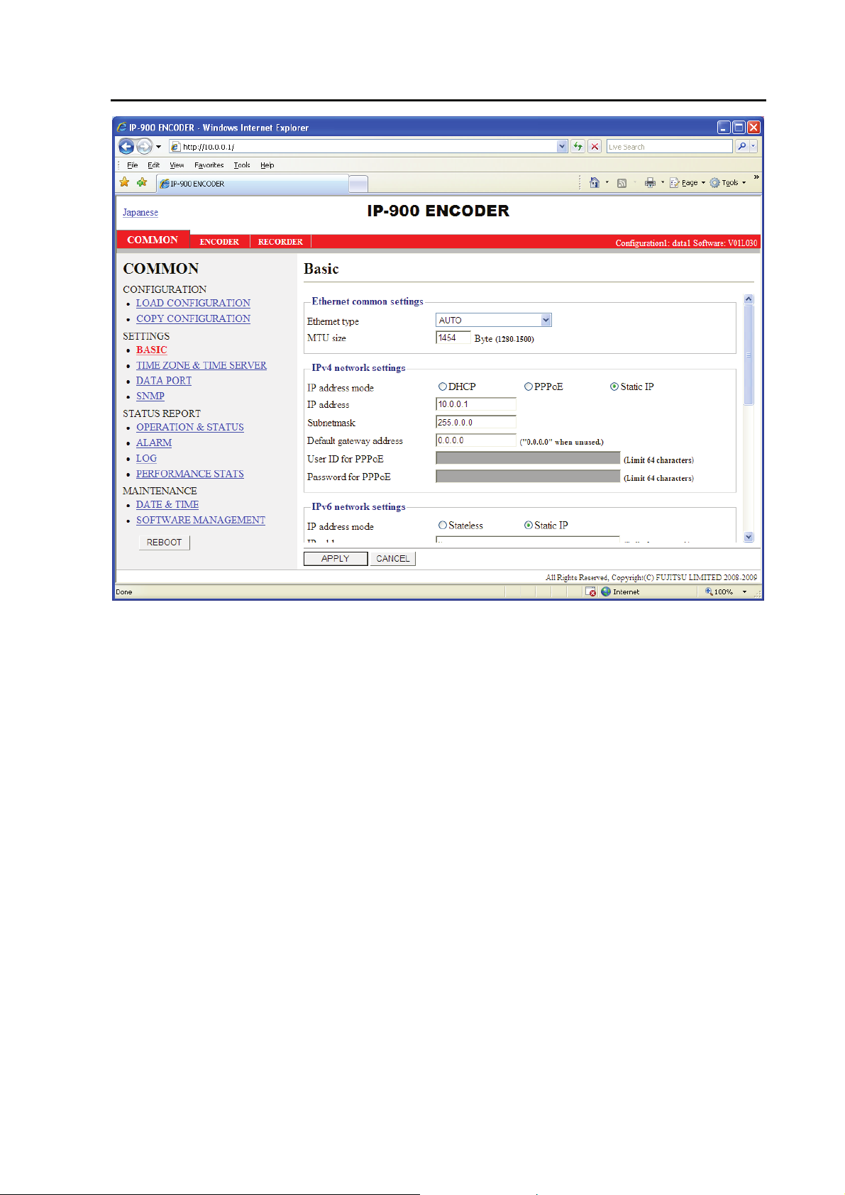
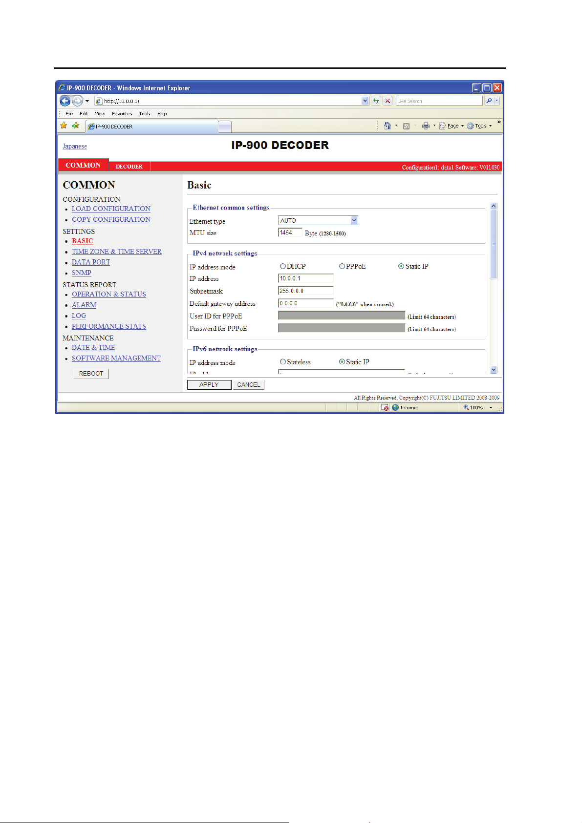
3.2.4 Basic
* Basic comprises a group of setting items, of which 10 sets can be r egister ed independently by
selecting data numbers as in 3.2.1 Configuration Data
You can set or change the settings of the parameters related to the network connection of IP-900
series or the operation mode in which it should operate after power-on. Make the required settings by
referring to Table 3-4 Basic Setting Items
.
IMPORTANT
If you operate IP-900 series with the default IP address, disconnect it from your network. Connect it
to the setting terminal via a hub or directly through a UTP cable. From the setting terminal, set it up to
meet the requirements for your network and then connect it to the network. If you connect it to your
network with the default IP address, an unexpected fault may occur in your network.
.
Figure 3-8 Basic Information Window
31
IP-900 Series
Page 38

Chapter 3 Web Operation
After the completion of the settings, click button. The message below appears.
Table 3-4 Basic Setting Items
Item Description Parameter
Ethernet
common
settings
MTU size Specify in bytes the maximum
IPv4 network
settings
IP address
Subnetmask
Default Gateway
User ID for
Ethernet type Select the LAN interface
operation mode.
size of IP packets to be sent to
the LAN.
IP address mode Specify the IPv4 address
acquisition method
Specify the IPv4 address when
address
PPPoE
"Static IP" is set for [IP address
mode].
Specify the IPv4 subnet mask
when "Static IP" is set for [IP
address mode].
Specify the default gateway
address of IPv4 when "Static
IP" is set for [IP address mode].
Specify the user ID when
"PPPoE" is set for [IP address
mode].
- AUTO (default)
- 100Base-TX Full
- 100Base-TX Half
- 10Base-T Full
- 10Base-T Half
1280 to 1500 bytes
(Default: 1454)
* For PPPoE, specify 1454 (recommended).
- DHCP
- PPPoE
- Static IP (Default)
IPv4 address other than the following:
224.0.0.0 to 239.255.255.255 (Class D)
240.0.0.0 to 255.255.255.255 (Class E)
0.0.0.0, 127.0.0.0 to 127.255.255.255
(Default: 10.0.0.1)
Subnet mask other than the following:
255.255.255.254,
255.255.255.255
(Default: 255.0.0.0)
IPv4 address other than the following:
224.0.0.0 to 239.255.255.255 (Class D)
240.0.0.0 to 255.255.255.255 (Class E)
127.0.0.0 to 127.255.255.255
(Default: None (represented as 0.0.0.0))
64 en-size alphanumeric characters
(Default: Blank)
IP-900 Series
32
Page 39

Chapter 3 Web Operation
Item Description Parameter
Password for
PPPoE
IPv6 network
settings
IP address
Prefix Specify the prefix of the IPv6
Default gateway
Other settings
User ID Specify the user name for
Password Specify the password for
WEB server title Specify the character string to
IP address mode Specify the IPv6 address
address
User
authentication
Specify the password when
"PPPoE" is set for [IP address
mode].
acquisition method.
Specify the IPv6 address when
"Static IP" is set for [IP address
mode].
address when "Static IP" is set
for [IP address mode].
Specify the default gateway
address when "Static IP" is set
for [IP address mode].
Specify whether to enable user
authentication for accessing the
Web screen.
authentication.
authentication.
be displayed on the title bar of
the Web screen. It will be used
to identify the Web screen with
the equipment name.
64 en-size alphanumeric characters
(Default: Blank)
- Stateless
- Static IP (default)
Global unicast IP address
2xxx:xxxx:…:xxxx to 3xxx:xxxx:…:xxxx
(Default: ::)
3 to 128
(Default: 64)
Global unicast address
2xxx:xxxx:...:xxxx to
3xxx:xxxx:...:xxxx
(Default: ::)
- Enable
- Disable (Default)
16 en-size alphanumeric characters
(Default: Blank)
16 en-size alphanumeric characters
(Default: Blank)
The specified string must be not exceed 64
bytes (assuming one double-space character
as 2 bytes and one single-space character as 1
byte).(Default: blank)
* Single-space kana characters are handled as
double-space characters.
Note: If power-on is performed in combination with the Cancel key (see IP-900 series User’s Guide),
the IP address and subnet mask on both LAN and CONSOLE ports are temporarily reset to the defaults
(LAN IPv4 address 10.0.0.1, subnet mask 255.0.0.0, IPv6 address :: and prefix: 64). If it becomes
unclear what an IP address is, connect the equipment with the defaults and use the setup menu to
confirm the IP address and subnet mask. In this case, the password restriction is also disabled. Hold
down the MNT button until the RDY LED starts blinking in orange. The equipment reboots, and the IP
address and subnet mask that were set for the equipment are restored.
33
IP-900 Series
Page 40

Chapter 3 Web Operation
3.2.5 Time Zone & Time Server
* Time Zone & Time Server is a group of setting items, of which 10 sets can be registered
independently by selecting data numbers as in 3.2.1 Configuration Data
Set the time zone and time server at the location where IP-900 series is installed. Click TIME ZONE
& TIME SERVER in the left frame of the Web screen. The Time Zone & Time Server window
appears in the right frame. Make settings according to the operation mode by referring to Table 3-5
Time Zone Setting Item and Table 3.6 Time Server Setting Items.
.
IP-900 Series
Figure 3-9 Time Zone & Time Server Window
34
Page 41

Chapter 3 Web Operation
After the completion of the settings, click button. The message below appears. Click
OK to apply the settings. *Reboot is not required.
Table 3-5 Time Zone Setting Item
Item Description Parameter
Time zone Select the time zone at the IP-900
series installation site.
UTC offset Specify the time difference from
Coordinated Universal Time (UTC)
when "UTC offset" is selected for
[Time zone].
(Default: Asia/Tokyo)
(Default: 0 Hours)
Table 3-6 Time Server Setting Items
Item Description Parameter
Auto
synchronization
Synchronization
interval
IP version Set the IP address version. - IPv4 (Default)
Server IP address Set the IP address of the time server.
Specify whether to automatically
synchronize with the time server.
Specify in minutes the interval in
which synchronization with the time
server is performed.
- Disable (Default)
- Enable
1 to 65535 minutes
(Default: 45)
- IPv6
Other than 0.0.0.0
(Default: 0.0.0.0)
* You cannot specify a multicast
address.
35
IP-900 Series
Page 42

Chapter 3 Web Operation
3.2.6 Data Port
* Data Port is a group of setting items, of which 10 sets can be registered independently by
selecting data number as in 3.2.1 Configuration Data
This setup is performed to enable data communication with another device on the IP network by
connecting the external device through the RS-232C port (D-sub 9-pin) provided at the rear of IP-900
series.
Click DATA PORT
frame, where you can set parameters for data communication with another device via the IP network.
Make the required settings by referring to Table 3-7 Data Port Setting Items
Operations Modes
in the left frame of the Web screen. The Data Port window appears in the right
.
and Table 3-8
IP-900 Series
Figure 3-10 Data Port Window
36
Page 43

Chapter 3 Web Operation
After the completion of the settings, click the button. The message below appears. Click
OK to apply the settings. *Reboot is not required.
Table 3-7 Data Port Setting Items
Item Description Parameter
Operation
settings
Port number
settings
RS-232C
settings
Data port Specify whether to use data port
communication.
Operation mode Specify the operation mode of data
port communication.
IP version Set the IP address version - IPv4 (Default)
Destination IP
address
Specify the IP address of the data
Server mode Specify the port number of the own
Client mode
Timeout Specify in milliseconds the reception
Specify the IP address of the data
communication destination when
"TCP client mode (bidirectional)" is
set for [Test mode].
communication destination when
"TCP client mode (bidirectional)" is
set for [Test mode].
device when "TCP server mode
(bidirectional)" is set for [Test mode].
Specify the port number of the own
device when "TCP client mode
(bidirectional)" is set for [Test mode].
Specify the port number of the
destination device when "TCP client
mode (bidirectional)" is set for [Test
mode].
timeout time for RS-232C.
- Enable
- Disable (Default)
- TCP server mode (bidirectional)
(Default)
- TCP server mode (receiving only)
- TCP client mode (bidirectional)
- IPv6
- IPv4 (Default)
- IPv6
Other than 0.0.0.0
(Default: 0.0.0.0)
1024 to 64000
(Default: 6000)
0 or 1024 to 64000
(Default: 0)
* If o is specified, a port number from
1024 to 4096 is automatically selected.
1024 to 64000
(Default: 6000)
20 to 200ms (Default: 20)
* The duration to detect a time-out is
defined as "the set value rounded down
by a multiple of '20[ms]'" + "RS-232C
polling interval of the device (20[ms])".
ex)
When '60' is set, the duration will be
'60' + '20' = 80 [ms]
When '50' is set, the duration will be
'40' + '20' = 60 [ms]
37
IP-900 Series
Page 44

Chapter 3 Web Operation
Item Description Parameter
Delimiter code 1 Specify the delimiter code 1 for
RS-232C.
Delimiter code 2 Specify the delimiter code 2 for
RS-232C.
Baud rate
Bit length Specify the RS-232C character size. 7 bits or 8 bits (Default)
Parity Specify whether to use RS-232C
Stop bits Specify the length of RS-232C stop
Flow control Specify whether to set RS-232C flow
Specify the RS-232C communication
speed.
parity.
bits.
control.
Blank or hexadecimal number between
00 and ff
(Default: Blank)
* A blank field means that no value is
specified.
Blank or hexadecimal number between
00 and ff
(Default: Blank)
* A blank field means that no value is
specified.
1200/2400/4800/9600 (Default)
/19200/38400 bps
None (Default), Odd or Even
1 bit (Default) or 2 bits
None (Default), RS or CS
Table 3-8 Operation Modes
Operation mode Description
(1)
TCP server mode
(bidirectional)
(2)
TCP server mode
(receiving only)
(3)
TCP client mode
(bidirectional)
* The following combinations of modes are available for data communication between IP-900 series:
(1) <-> (3)
(2) <-> (3)
Bidirectional data communication is performed between the data port and
another device connected via the IP network. IP-900 series waits, at the
specified port number, for access through socket connection from the
destination device. (IP address setting is not required.)
Data received from another device connected via the IP network is output to
the data port. Data received from the data port is not sent to the destination.
IP-900 series waits, at the specified port number, for access through socket
connection from the destination device. (IP address setting is not required.)
Bidirectional data communication is performed between the data port and
another device connected via the IP network. IP-900 series sets up a socket
connection through the specified port to the device with the specified IP
address.
IP-900 Series
38
Page 45

Chapter 3 Web Operation
3.2.7 SNMP
* SNMP is a group of setting items, of which 10 sets can be registered independently by
selecting data numbers as in 3.2.1 Configuration Data.
Click SNMP
where you can set parameters for SNMP with the counterpart device via the IP network. Make the
required settings by referring to Table 3-9 SNMP Setting Items
in the left frame of the Web screen. The SNMP window appears in the right frame,
.
Figure 3-11 SNMP Window
39
IP-900 Series
Page 46

Chapter 3 Web Operation
After the completion of the settings, click the button. The message below appears.
Click OK to apply the settings. * Reboot is not required.
Table 3-9 SNMP Setting Items
Item Description Parameter
SNMP Agent Specify whether to enable SNMP agent. - Disable (Default)
- Enable
Manager #N
SNMP version Specify the SNMP version of SNMP
manager.
Community
name
Specify the community name to accept
the SNMP request from the SNMP
manager.
- SNMPv1 (Default)
- SNMPv2c
Alphanumeric 16 characters
(Default: Blank)
IP version Specify the IP version of the IP address
of SNMP manager.
IP address Specify the IP address of SNMP
manager.
(Max. 10 managers can be registered.)
- IPv4 (Default)
- IPv6
An IP address other than
0.0.0.0
(Default: Blank)
* A blank field means that no
value is specified.
* You cannot specify a
multicast address.
IP-900 Series
40
Page 47

Chapter 3 Web Operation
3.2.8 Operation & Status (Common)
Click OPERATION & STWATUS in the left frame of the Web screen. The Operation & Status
window appears in the right frame, where you can check the status of equipment operation such as the
state of LAN operation. For details, see Table 3-10 Operation & Status Display Items
Selecting {3 sec, 5sec, or 10sec} from [Auto update] enables automatic updating of the performance
data in specified time intervals. Selecting {none} from [Auto update] disables automatic updating.
.
Figure 3-12 Operation & Status Window
IP-900 Series
41
Page 48

Chapter 3 Web Operation
Table 3-10 Operation & Status Display Items
Item Display
Serial number Displays the serial number
IP address (IPv4) {DHCP/PPPoE/Static IP}
Displays the IPv4 address acquisition mode.
[xxx.xxx.xxx.xxx (IPv4)]
Displays the IPv4 address.
xxx.xxx.xxx.xxx: IPv4 address
Subnetmask (IPv4) xxx.xxx.xxx.xxx
Displays the IPv4 subnet mask.
xxx.xxx.xxx.xxx: Subnet mask
Default gateway address (IPv4) xxx.xxx.xxx.xxx
Displays the default gateway address of IPv4.
xxx.xxx.xxx.xxx: Default gateway address
IP address (IPv6)
[yyyy:yyyy: ... :(IPv6)]
Default gateway address (IPv6) xxxx:xxxx: ... :xxxx
LAN MAC address Displays the MAC address.
LAN link
Time server {Normal / Fault / Synchronization failure/ ---}
Link-Local/[xxxx:xxxx: ... :xxxx(IPv6)]
Displays the IPv6 link-local address.
xxxx:xxxx: ... :xxxx: Link-Local address
{Stateless/Static IP}
Displays the IPv6 address acquisition method.
* If the IPv6 address acquisition method is "Stateless," up to four sets of global
unicast address/prefix are displayed according to the address acquisition
status.
Displays the IPv6 global unicast address.
yyyy:yyyy: ... :yyyy: Global unicast address
[zzz]
Displays the prefix of the IPv6 global unicast address.
zzz: Prefix
Displays the default gateway address of IPv6.
xxx:xxx. ... :xxx: Default gateway address
* If the IPv6 address acquisition method is "Stateless," up to four default
gateway addresses are displayed according to the address acquisition status.
{Connected / Disconnected}
Displays the LINK status.
{100Base-TX Full Duplex / 100Base-TX Half Duplex / 10Base-T Full
Duplex / 10Base-T Half Duplex}
Displays the LAN interface operation status.
Displays the status of synchronization with the specified time server.
IP-900 Series
42
Page 49

Chapter 3 Web Operation
Item Display
Data port {Normal/Fault/---}
Displays the communication status of data port communication.{TCP server
mode (bidirectional)/TCP server mode (receiving only)/TCP client mode
(bidirectional)}
Displays the operation mode of data port communication.
{IP address}
Displays the IP address of the destination device for data port
communication.
- TCP server mode / TCP server mode (receiving only)
Displays the IP address of the destination device when data port
communication is established.
(Displays 0.0.0.0 when no communication is set up.)
- TCP client mode
Displays the IP address of the destination device for data port
communication.
{Port number}
Displays the port number of the destination device for data port
communication.
- TCP server mode / TCP server mode (receiving only)
Displays the port number of the destination device when data port
communication is established.
- TCP client mode
Displays the port number of the destination device for data port
communication.
SNMP {Normal / ---}
Display the status of the SNMP agent.
Component temperature Displays the internal temperature (ºC) of the equipment.
* Notation: {A/B} indicates that either A or B is displayed.
43
IP-900 Series
Page 50

Chapter 3 Web Operation
3.2.9 Alarm
Click ALARM in the left frame of the Web screen. The Alarm window appears in the right frame,
where you can check the alarm list. For details, see Table
Selecting {3 sec, 5sec, or 10sec} from [Auto update] enables automatic updating of the performance
data in specified time intervals. Selecting {none} from [Auto update] disables automatic updating.
3-11 Alarm List.
IP-900 Series
Figure 3-13 Alarm Window
44
Page 51

Chapter 3 Web Operation
Table 3-11 Alarm List
Code Name Description Details (The part after the * mark is not displayed.)
I001 SDI input down HD/SD-SDI input signal not detected −
I002 HDMI input down HDMI input signal not detected −
I003 Analog input down Analog video input signal not detected −
I011 Video synchronization error Video input synchronization failure −
I021 Input data error (*7) Count-up occurred in the performance
statistics error counter
E001 Power error (*1) Power failure occurred
E003 Temperature error occurrence (*5) Extreme temperature (shutdown
processing started)
E004 Flash ROM error (*1) Internal flash ROM access error occurred
E00A Flash ROM check sum error (*1) Operation data error detected in internal
Flash ROM
E010 FAN error (*2) FAN error (low speed) or stopped xxxRPS * xxx: FAN rotational speed
#xxxxxxxxxxxxxxxx
* 64-bit hexadecimal number. For the meaning of
each bit, see Table 3-12, "Bit Formats for Input Data
Errors."
#1 * Power failure on CNT board
#2 * Power failure on COD board
#1 TEMP1=t1 TEMP2=t2 FAN=xxxRPS
#2 TEMP1=t1 TEMP2=t2 FAN=xxxRPS
* Details are as follows:
#1/#2: Number of the temperature sensor that has
detected a temperature error
t1: Temperature indicated by temperature sensor 1
t2: Temperature indicated by temperature sensor 2
xxx: FAN rotational speed
/dev/mtd0 to 15
* Displays the occurrence range of access error.
software
bundle software
configuration
configuration#1〜#10
option
* Displays the occurrence range of check sum errors.
45
IP-900 Series
Page 52

Chapter 3 Web Operation
Code Name Description Details (The part after the * mark is not displayed.)
E013 Temperature warning (*2) Thermal alarm (alarm only) detected #1 TEMP1=t1 TEMP2=t2 FAN=xxxRPS
#2 TEMP1=t1 TEMP2=t2 FAN=xxxRPS
* Details are as follows:
#1/#2: Number of the temperature sensor that has
detected a temperature error
t1: Temperature indicated by temperature sensor 1
t2: Temperature indicated by temperature sensor 2
xxx: FAN rotational speed
E082 CODEC1 error (*4) Main CODEC LSI error detected −
E083 CODEC2 error (*4) Sub CODEC LSI error detected −
E084 CF card access error (*3) CF card access failure detected −
E085 CF card power error (*3) Overcurrent to CF card detected −
E08B SUB CPU1 error (*4) SUB CPU1 error detected −
E08C SUB CPU2 error (*4) SUB CPU2 error detected−
E08E Clock error (*1) Clock error or interruption detected #1 to #4 * Indicates the location where a clock error
has occurred.
E08F Memory error (*1) SDRAM memory check error detected #1 to #7 * Indicates the location where a memory
error has occurred.
E093 Sending buffer overflow (*6) Sending buffer overflow occurred #1, #2 * Indicates the location where a sending buffer
overflow has occurred.
If an alarm recovers occurs after an alarm occurrence.
*1: After occurrence of this error, the ALM LED remains on. The device needs to be rebooted to turn off the ALM LED.
*2: The ALM LED blinks while this alarm is active. The LED goes off when the alarm cause is recovered.
*3: After occurrence of this error, the ALM LED remains to blink.
*4: After occurrence of this error, the operation is retired for recovery. If the retry for recovery is unsuccessful, the ALM LED remains on. The device needs to be
rebooted to turn off the ALM LED.
*5: If an extreme temperature is detected, all LEDs except LINK/ACT, 10/100 go on. The device needs to be rebooted to turn off the LEDs.
*6: The ALM LED blinks while this alarm is active. The LED goes off when the alarm cause is recovered.
In case that the settings exceeds the capacity of the IP network, please reconfigure them to meet the network requirement
*7: The IN DWN LED blinks while this alarm is active. The LED goes off 10 seconds after the error cause is recovered. See 3. 2. 11 Performance Statistics for the
details of the statistical information counter about the alarm occurrence.
IP-900 Series
46
Page 53

Table 3-12 Input data error bit format
Bit 63 62 61 60 59 - 0
Type Decoder Undefined
Interface
IP
IP
IP
IP
Chapter 3 Web Operation
Number of audio decoding errors
Undefined
Performance statistics
Number of reloading TS stream
Number of discontinuous PCR
Number of video decoding errors
IP-900 Series
47
Page 54

Chapter 3 Web Operation
3.2.10 Log
Click LOG in the left frame of the Web screen. The Log window appears in the right frame, where
you can check the alarm log. For details, see
If you click the
* Up to 100 log items per page can be saved to up to 10 pages (1,000 log items in total). Log items
exceeding 1,000 items are overwritten beginning with the chronologically oldest items.
button, the alarm log is detected completely.
Table 3-13 Log Type.
IP-900 Series
Figure 3-14 Log Window
48
Page 55

Chapter 3 Web Operation
Table 3-13 Log Type
Code Name Description Details (The part after the * mark is not displayed.)
0001 Boot (Power ON) Normal start using the switch VxxLxxxCxx yyyy
* Displays the software version and configuration name.
VxxLxxxCxx: Software version
yyyy: Configuration name
0002 Boot (Reset) Normal start by reboot VxxLxxxCxx yyyy
* Displays the software version and configuration name.
VxxLxxxCxx: Software version
yyyy: Configuration name
0004 Boot (Initial maintenance) Normal start using the factory-shipped
firmware
0005 Boot (Maintenance) Normal start in maintenance mode VxxLxxxCxx yyyy
* Displays the software version and configuration name.
VxxLxxxCxx: Software version
yyyy: Configuration name
0006 Software update Software update VxxLxxxCxx -> VyyLyyyCyy
* Displays the new and old software versions.
VxxLxxxCxx: Old software version
VyyLyyyCyy: New software version
0007 Boot (Restart) (*6) Restarted owing to CPU failure VxxLxxxCxx yyyy
* Displays the software version and configuration name.
VxxLxxxCxx: Software version
yyyy: Configuration name
0008 Boot (Others) (*6) Restarted owing to software failure VxxLxxxCxx yyyy
* Displays the software version and configuration name.
VxxLxxxCxx: Software version
yyyy: Configuration name
0009 Shutdown Shut down by MNT button −
000A RTC initialization RTC battery backup failure −
000B CF card initialization CF card format error −
000C Configuration update Operation data update −
000D Basic settings change Change basic setting −
−
49
IP-900 Series
Page 56

Chapter 3 Web Operation
Code Name Description Details (The part after the * mark is not displayed.)
000E Configuration data switching Switch configuration data xxxx -> yyyy
* Displays the old and new configuration names.
xxxx: Old configuration name
yyyy: New configuration name
000F Operation data initialization Operation data initialized −
0010 Option update Option installed HD
L001 LINK error (LAN) Link disconnection at a LAN port
occurred
*L001 Link alarm recovery Recovered from link disconnection at a
LAN port
L006 Time server synchronization failure Time synchronization with the time server
failed
*L006 Time server synchronization Time acquisition from the time server was
successful
L009 DHCP connection failure DHCP server is disconnected −
*L009 DHCP connection Connected to the DHCP server xxx.xxx.xxx.xxx/yy,zzz.zzz.zzz.zzz
L00A PPPoE connection failure PPPoE server is disconnected −
*L00A PPPoE connection Connected to the PPPoE server xxx.xxx.xxx.xxx/yy,zzz.zzz.zzz.zzz
10BaseT_HD/10BaseT_FD/100BaseTX_HD/100Base
TX_FD
* Displays the operating status of the LAN interface
* Displays the IPv4 address acquired from the DHCP
server.
xxx.xxx.xxx.xxx: IPv4 address
yy: Subnet mask bit count
zzz.zzz.zzz.zzz: Gateway address
* Displays the IPv4 address acquired from the PPPoE
server.
xxx.xxx.xxx.xxx: IPv4 address
yy: Subnet mask bit count
zzz.zzz.zzz.zzz: Gateway address
−
−
−
IP-900 Series
50
Page 57

Chapter 3 Web Operation
Code Name Description Details (The part after the * mark is not displayed.)
L00E DHCP connection update IP address change occurred during DHCP
connection
L00F PPPoE connection update IP address change occurred during PPPoE
connection
L010 Stateless address acquisition failure IPv6 stateless address acquisition failed
*L010 Stateless address acquisition IPv6 stateless address acquired xxxx:xxxx:…:xxxx/yy
L011 Stateless address update IPv6 stateless address update occurred xxxx:xxxx:…:xxx1/y1 -> xxxx:xxxx:…:xxx2/y2
I001 SDI input down HD/SD-SDI input signal not detected −
*I001 SDI input down recovery Normal HD/SD-SDI input −
xxx.xxx.xxx.xx1/y1,zzz.zzz.zzz.zz1 ->
xxx.xxx.xxx.xx2/y2,zzz.zzz.zzz.zz2
* Displays the old and new IPv4 addresses acquired
from the DHCP server.
xxx.xxx.xxx.xx1: Old IPv4 address
y1: Old subnet mask bit count
zzz.zzz.zzz.zz1: Old gateway address
xxx.xxx.xxx.xx2: New IPv4 address
y2: New subnet mask bit count
zzz.zzz.zzz.zz2: New gateway address
xxx.xxx.xxx.xx1/y1,zzz.zzz.zzz.zz1 ->
xxx.xxx.xxx.xx2/y2,zzz.zzz.zzz.zz2
* Displays the old and new IPv4 addresses acquired from
the PPPoE server. xxx.xxx.xxx.xx1: Old IPv4 address
y1: Old subnet mask bit count
zzz.zzz.zzz.zz1: Old gateway address
xxx.xxx.xxx.xx2: New IPv4 address
y2: New subnet mask bit count
zzz.zzz.zzz.zz2: New gateway address
* Displays the IPv6 address acquired from the router.
xxxx:xxxx: … :xxxx: IPv6 address
yy: Subnet prefix length
* Displays the old and new IPv6 addresses acquired from
the router.
xxxx:xxxx: … :xxx1: Old IPv6 address
y1: Old subnet prefix length
xxxx:xxxx: … :xxx2: New IPv6 address
y2: New subnet prefix length
51
IP-900 Series
Page 58

Chapter 3 Web Operation
Code Name Description Details (The part after the * mark is not displayed.)
I002 HDMI input down HDMI input signal not detected −
*I002 HDMI input down recovery Normal HDMI input −
I003 Analog input down Analog video input signal not detected
*I003 Analog input down recovery Normal analog video input
I011 Video input synchronization error Video input PLL synchronization error
occurred
*I011 Video input synchronization error
recovery
I021 Input data error (*8) Count-up occurred in the performance
*I021 Input data error recovery (*8) Recovered from count-up of the
E001 Power error (*1) Power failure occurred
E003 Temperature error occurrence (*5) Extreme temperature (shutdown processing
E004 Flash ROM error (*1) Internal flash ROM access error occurred
E00A Flash ROM check sum error (*1) Operation data error detected in internal
E010 FAN error (*2) FAN error (low speed) or stopped xxxRPS * xxx: FAN rotational speed
*E010 FAN error recovery (*2) FAN speed recovery xxxRPS * xxx: FAN rotational speed
Recovered from video input PLL
synchronization error
statistics error counter
performance statistics error counter
started)
Flash ROM
#xxxxxxxxxxxxxxxx
* 64-bit hexadecimal number. For the meaning of each
bit, see Table 3-12, "Input data error bit format".
#1 * Power failure on CNT board
#2 * Power failure on COD board
* Details are as follows:
#1/#2: Number of the temperature sensor that has
detected a temperature error
t1: Temperature indicated by temperature sensor 1
t2: Temperature indicated by temperature sensor 2
xxx: FAN rotational speed
/dev/mtd0 to 15
* Displays the occurrence range of access error.
Software
bundle software
configuration
configuration#1〜#10
* Displays the occurrence range of check sum errors.
−
−
−
IP-900 Series
52
Page 59

Chapter 3 Web Operation
Code Name Description Details (The part after the * mark is not displayed.)
E013 Temperature warning (*2) Thermal alarm (alarm only) detected #1 TEMP1=t1 TEMP2=t2 FAN=xxxRPS
#2 TEMP1=t1 TEMP2=t2 FAN=xxxRPS
* Details are as follows:
#1/#2: Number of the temperature sensor that has
detected a thermal alarm
t1: Temperature indicated by temperature sensor 1
t2: Temperature indicated by temperature sensor 2
xxx: FAN rotational speed
*E013 Thermal alarm recovery (*2) Recovered from thermal alarm #1 TEMP1=t1 TEMP2=t2 FAN=xxxRPS
#2 TEMP1=t1 TEMP2=t2 FAN=xxxRPS
* Details are as follows:
#1/#2 : Number of the temperature sensor that has
detected a thermal alarm recovery
t1: Temperature indicated by temperature sensor 1
t2: Temperature indicated by temperature sensor 2
xxx: FAN rotational speed
E082 CODEC1 error (*4) Main HD CODEC LSI error detected −
*E082 CODEC1 error recovery (*4) Recovered from main CODEC LSI error −
E083 CODEC2 error (*4) Sub CODEC LSI error detected −
*E083 CODEC2 error recovery (*4) Recovered from sub CODEC LSI error −
E084 CF card access error (*3) CF card access failure detected −
E085 CF card power error (*3) Overcurrent to CF card detected −
E08B SUB CPU1 error (*4) SUB CPU1 error detected −
*E08B SUB CPU1 error recovery (*4) Recovered from SUB CPU1 error −
E08C SUB CPU2 error (*4) SUB CPU2 error detected −
*E08C SUB CPU2 error recovery (*4) Recovered from SUB CPU2 error −
E08E Clock error (*1) Clock error or interruption detected #1 to #4 * Indicates the location where a clock error
has occurred.
E08F Memory error (*1) SDRAM memory check error detected #1 to #7 * Indicates the location where a memory error
has occurred.
E093 Sending buffer overflow (*7) Sending buffer overflow occurred #1, #2 * Indicates the location where a sending buffer
overflow has occurred.
53
IP-900 Series
Page 60

Chapter 3 Web Operation
Code Name Description Details (The part after the * mark is not displayed.)
*E093 Sending buffer overflow recovery (*7) Recovered from sending buffer overflow #1, #2 * Indicates the location of sending buffer
overflow recovery.
*1: After occurrence of this error, the ALM LED remains on. The device needs to be rebooted to turn off the ALM LED.
*2: The ALM LED blinks while this alarm is active. The LED goes off when the alarm cause is recovered.
*3: After occurrence of this error, the ALM LED remains to blink.
*4: After occurrence of this error, the operation is retried for recovery. If the retry for recovery is unsuccessful, the ALM LED remains on. The device needs to be
rebooted to turn off the ALM LED.
*5: If an extreme temperature is detected, all LEDs except LINK/ACT, 10/100 go on. The device needs to be rebooted to turn off the LEDs.
*6: The ALM LED is on while this alarm is active. The LED goes off when the error cause is recovered.
*7: The ALM LED blinks while this alarm is active. The LED goes off when the alarm cause is recovered.
In case that the settings exceeds the capacity of the IP network, please reconfigure them to meet the network requirement.
*8: The IN DWN LED blinks while this alarm is active. The LED goes off 10 seconds after the error cause is recovered. See 3. 2. 11 Performance Statistics for the
details of the statistical information counter about the alarm occurrence.
If an alarm occurs, the Fujitsu maintenance engineer may ask you to collect not only alarm log information but also detailed log information about the
inside of the device. Save the detailed log information to a personal computer by clicking the [GET LOG] button, and then hand it over to the
maintenance engineer.
IP-900 Series
54
Page 61

Chapter 3 Web Operation
3.2.11 Performance Statistics
Click PERFORMANCE STATS in the left frame of the Web screen. The Performance Statistics
window appears in the right frame. Select the port from {Main Encoder (Ethernet), Sub Encoder,
Decoder (Ethernet) or Data Port } and the interval from {All, Hour, Day, Week or Month} and then
click to check the various types of performance data shown in Table 3-14 Performance Statistics
.
Items
Selecting {3sec, 5sec, or 10sec} from [Auto update] enables automatic updating of the performance
data in specified time intervals. Selecting {none} from [Auto update] disables automatic updating.
Clicking the
button deletes all performance data.
Figure 3-15 Performance Statistics Window Main Encoder
55
IP-900 Series
Page 62

Chapter 3 Web Operation
Figure 3-16 Performance Statistics Window Sub-encoder
IP-900 Series
56
Page 63

Chapter 3 Web Operation
Figure 3-17 Performance Statistics Window Decoder
57
IP-900 Series
Page 64

Chapter 3 Web Operation
Figure 3-18 Performance Statistics Window Data Port
IP-900 Series
58
Page 65

Table 3-14 Performance Statistics Items
Port Item Description Display
Main
Encoder
(Ethernet)
* Displayed
only for
encoder
Sub Encoder
* Displayed
only for
encoder
Decoder
(Ethernet)
* Displayed
only for
decoder
Number of data
packets sent
Number of FEC
packets sent
Number of ARQ
request received
Number of ARQ
packets resent
Number of data
packets sent
Number of FEC
packets sent
Number of ARQ
request received
Number of ARQ
packets resent
Number of data
packets received
Number of data
packets recovered
Number of data
packets lost
Number of FEC
packets received
Number of ARQ
packets received
Number of data
packets recovered
by FEC
Number of ARQ
request sent
Number of data
packets recovered
by ARQ
Number of data
loss exceeding
concealment time
Displays the number of audio and
video data packets sent.
Displays the number of
FEC/Pro-MPEG FEC packets sent.
Displays the number of ARQ
requests received.
Displays the number of ARQ
packets resent.
Displays the number of audio and
video data packets sent.
Displays the number of
FEC/Pro-MPEG FEC packets sent.
Displays the number of ARQ
requests received.
Displays the number of ARQ
packets resent.
Displays the number of audio and
video data packets received.
Displays the number of media
packets recovered by the
FEC/Pro-MPEG FEC/ARQ error
correction function.
Displays the number of data
packets that were abandoned on
the network and could not be
received.
Displays the number of
FEC/Pro-MPEG FEC packets sent.
Displays the number of data
packets received by ARQ.
Displays the number of packets
recovered with the
FEC/Pro-MPEG FEC method.
Displays the number of ARQ
request packets sent when a packet
was lost.
Displays the number of data
packets recovered by ARQ.
3.5.1 Setting (Decoder)
Displays the number of displaying
“blue” or “gray” image not
receiving data for longer time than
the setting value of [Packet
non-receiving recognition time].
{-----}
The counter restarts counting from 0 after it
expires.
{-----}
The counter restarts counting from 0 after it
expires.
{-----}
The counter restarts counting from 0 after it
expires.
{-----}
The counter restarts counting from 0 after it
expires.
{-----}
The counter restarts counting from 0 after it
expires.
{-----}
The counter restarts counting from 0 after it
expires.
{-----}
The counter restarts counting from 0 after it
expires.
{-----}
The counter restarts counting from 0 after it
expires.
{-----}
The counter restarts counting from 0 after it
expires.
{-----}
The counter restarts counting from 0 after it
expires.
{-----}
The counter restarts counting from 0 after it
expires.
{-----}
The counter restarts counting from 0 after it
expires.
{-----}
The counter restarts counting from 0 after it
expires.
{-----}
The counter restarts counting from 0 after it
expires.
{-----}
The counter restarts counting from 0 after it
expires.
{-----}
The counter restarts counting from 0 after it
expires.
{-----}
The counter restarts counting from 0 after it
expires.
Chapter 3 Web Operation
59
IP-900 Series
Page 66

Chapter 3 Web Operation
Port Item Description Display
{-----}
The counter restarts counting from 0 after it
expires.
{-----}
The counter restarts counting from 0 after it
expires.
{-----}
The counter restarts counting from 0 after it
expires.
{-----}
The counter restarts counting from 0 after it
expires.
{-----}
The counter restarts counting from 0 after it
expires.
{-----}
The counter restarts counting from 0 after it
expires.
{-----}
The counter restarts counting from 0 after it
expires.
{-----}
The counter restarts counting from 0 after it
expires.
{-----}
The counter restarts counting from 0 after it
expires.
Data port
Number of
reloading TS
stream
Number of
discontinuous PCR
(*1)
Number of jitter
control buffer
exceeded capacity
Number of video
decoding errors
(*1)
Number of audio
PES format
mismatch
Number of audio
decoding errors
(*1)
Number of data
received in byte on
RS-232C
Number of data
sent in byte on
RS-232C
Number of data
received in byte on
LAN port
Displays the number of reloading
TS stream without packets
recovery because of many packets
lost.
*In the following situation, the
number is counted.
3.5.1 Setting (Decoder)
- [ARQ operation] is performed.
- When the number of data packets
lost is 4000 or more
- [ARQ operation] is not
performed.
- When the number of data packets
lost is 24 packets or more.
Displays the number of
discontinuous PCR values detected
during decoding.
Displays the number of video skip
or repeat that occurs when the
decoder cannot absorb the network
jitter of the reception packets
*) It can be lowerd by increasing
“Jitter control buffer” in “3.5.1
Setting (Decoder)”.
*) Its counter may increase even if
there is no network jitter when the
decoder receives the stream which
video resolution is set to 352x288
or lower in “3.3.1 Setting
(Encoder)”, or which is generated
by Fujitsu IP-700II.
Displays the number of video
decoding errors detected during
decoding.
Displays the number of times that
an audio PES packet that the
decoder does not regard as being
applicable to decoding is received.
This is counted specifically in the
following cases.
・ For MPEG-1 Layer 2/MPEG2
AAC
-During reception of an audio
stream that is not 1PES/1AAU.
Displays the number of audio
decoding errors detected during
decoding.
Displays the number of data bytes
received through the RS-232C
port.
Displays the number of data bytes
sent to the RS-232C port.
Displays the number of data bytes
received through the LAN port.
IP-900 Series
60
Page 67

Chapter 3 Web Operation
Port Item Description Display
Number of data
sent in byte on
LAN port
Displays the number of data bytes
sent to the LAN port.
{-----}
The counter restarts counting from 0 after it
expires.
Note: Each counter, consisting of 32 bits, can count up to 4294967295.
* 1. In case the count-up is made in this counter, IN DWN LED blinks for 10 seconds, I021 (Input data
error) is saved as the log information.
61
IP-900 Series
Page 68

Chapter 3 Web Operation
3.2.12 Date & Time
Two types of setting modes are available. In one mode, you can enter arbitrary date and time data. In
another mode, you can instruct the system to synchronize with the time server on the network.
Click DATE & TIME
right frame, where you can set the date and time of the clock built in IP-900 series.
Clicking the
button after entering an arbitrary date and time sets the specified date and time.
Clicking the
specified in Section 3.2.5, "Time Zone & Time Server." This function is enabled only when "Enable" is
specified for Auto Synchronization.
* Any date and time between 00:00:00 on January 1, 1980 and 23:59:59 on December 31, 2030 can
be specified.
in the left frame of the Web screen. The Date & Time window appears in the
button sets the date and time of the PC. Clicking the
button promptly adjusts the time with the time server
IP-900 Series
Figure 3-19 Date & Time Window
62
Page 69

Chapter 3 Web Operation
3.2.13 Software Management
Click SOFTWARE MANAGEMENT in the left frame of the Web screen. The Software Management
window appears in the right frame, where you can install software or restore, save or delete
configuration data.
Figure 3-20 Software Management Window
■ Software
Specify the new file to be installed, enter the license key and click the button to start
installing the software.
■ Configuration
● Configuration Restoration
Specify the file containing all configuration data and then click the
restore all the configuration data, which was saved previously, to IP-900 series.
● Configuration Backup
All the configuration data currently stored in IP-900 series can be backed up to the PC by clicking
the
button.
IP-900 Series
63
button to
Page 70

Chapter 3 Web Operation
● Deletion of the configuration data
All the configuration data currently stored in IP-900 series can be initialized by clicking the
button. This operation also resets information including the IP address to the state
before shipment from the factory.
Table 3-15 Software Management Items
Item Description
Software
Configuration
Option
Current software version Displays the software version.
V-- L-- C-- is displayed immediately after shipment from the
factory.
New software Specify the full path of the file to be installed. The Browse
button can also be used to select the file.
Configuration file to be
restored
RESTORE Use this button to restore all the configuration data.
BACKUP Use this button to back up all the configuration data from the
DELETE ALL Use this button to delete all the configuration data from the
Option license key Enter the license key obtained when the optional license was
Installed option Names of installed options are displayed.
To restore all the configuration data, specify the full path of the
file. The Browse button can also be used to select the file.
This button is enabled when a file name is specified in the
"Configuration file to be restored" field.
IP-900 series to the PC.
IP-900 series.
This operation resets all the configuration data to the default.
purchased.
If all the configuration data is changed (restored or deleted), the IP address, subnet mask, and gateway
may be changed. Note that this may cause an unexpected problem in your network.
Do not turn power off or press the MNT button while all the configuration data is being changed
(being restored or deleted). Doing so may prevent
IP-900 series from starting.
If you access another Web screen while all the configuration data is being changed (being restored or
deleted), you may lose information on the progress of the changing.
IP-900 Series
64
Page 71

3.2.14 Reboot
Click the button in the left frame of the Web screen. The dialog box shown below appears for
confirmation. Click the OK button to reboot.
Chapter 3 Web Operation
65
IP-900 Series
Page 72

Chapter 3 Web Operation
3.3 Encoder
3.3
3.3.1 Setting (Encoder)
* Settings is a group of setting items, of which 10 sets can be registered independently by
selecting data numbers as in 3.2.1 Configuration Data
Set parameters related to encoding. Make the required settings by referring to Table 3-17 Main encoder /Sub
encoder System Bit Rate Setting Range
Summary
Setting Summary (in case of 720x480, 352x480 , 720x576 and 352x576 video resolution)
encoder SD: Video Setting Summary (in case of 352x240, 176x112, 352x288, 176x144 video resolution)
Table 3-22 Main encoder HD/SD & Sub encoder HD/SD: Audio Setting Summary
, Table 3-19 Main encoder SD: Video Setting Summary, Table 3-20 Sub encoder SD: Video
The same screen is displayed for SETTINGS, Video and Audio under <AV input settings>, Main
encoder ethernet and Sub encoder ethernet under <Output interface settings>, Encode under <Main
encoder settings>, and Encode under <Sub encoder settings>, which are located in the frame on the left
side of the Web screen. By clicking on the tab for each, the settings screen for each is displayed at the
top of the frame on the right side.
, Table 3-18 Main encoder HD / Sub encoder HD: Video Setting
.
, Table 3-21 Sub
,
IP-900 Series
66
Page 73

Chapter 3 Web Operation
Figure 3-21 Settings Screen (Encoder)
67
IP-900 Series
Page 74

Chapter 3 Web Operation
After the completion of the settings, click the button. The message below appears. Click OK
to apply the settings. * Reboot is not required.
Table 3-16 Encoder Setting Items
Item Description Parameter
CPU utilization Displays the CPU utilization for IP
streaming. The CPU utilization
increases in accordance with the
Ethernet rate of the main encoder
and sub encoder. No settings can
be made that will cause the CPU
utilization to exceed 100%.
Main
encoder
Sub encoder
AV input
settings
(Video)
Ethernet bit rate Displays in units of bps the
Ethernet bit rate for the main
encoder that is currently set.
System bit rate Displays in units of bps the system
bit rate for the main encoder that is
currently set.
Ethernet bit rate Displays in units of bps the
Ethernet bit rate for the sub
encoder that is currently set.
System bit rate Displays in units of bps the system
bit rate for the sub encoder that is
currently set.
Video input port
Video resolution
Video format
Specify the interface for video
signal input.
* HDMI input does not support
HDCP. Signals encrypted for the
purpose of copyright protection
cannot be input.
Specify the input resolution of the
video signal.
* The contents that can be set
depend on the [Video input port]
setting.
* To specify HD, the HD software
option needs to have been
installed.
Specify the input format of the
video signal.
* The contents that can be set
depend on the [Video resolution]
setting.
You cannot specify this item.
You cannot specify this item.
You cannot specify this item.
You cannot specify this item.
You cannot specify this item.
- SDI (Default)
- HDMI
- Analog
- SD (Default)
- HD
Values available when [Video resolution] is
"HD":
- 1080i/59.94
- 1080i/50
- 1080i/60
- 720p/59.94
- 720p/50
IP-900 Series
68
Page 75

Chapter 3 Web Operation
Item Description Parameter
Values available when [Video resolution] is
"SD":
- 480i/59.94 (Default)
- 576i/50
Analog video setup * If "Analog" is specified for
[Video input port], specify the
setup level of the analog video
input signal.
Analog video AGC * If "Analog" is specified for
[Video input port], specify whether
to enable automatic gain control of
the analog video input signal.
Display when no
video input signal
Buffer for video
input
AV input
settings
(Audio)
Output
interface
settings
(Main
encoder
ethernet)
Acceptable stream
Streaming
Audio input port
IP version Specify the IP version of the IP
Streaming mode Specify the streaming method for
number
destination IP
address
Specify the fixed image to be sent
when the video input is
interrupted.
Specify whether to enable the
protection buffer for video signal
input.
* If "Enable" is specified, a delay
of up to 1 frame is caused, but
video input error resistance is
improved.
Specify the input format of the
audio signal.
* The contents that can be set
depend on the [Video input port]
setting.
stream for streaming.
the IP interface.
Specify the number of possible
streams.
* The contents that can be set
depend on the [System bit rate]
setting.
* If "Multicast" or "Unicast
(simplex)" is specified for
[Streaming mode], only "1" can be
specified.
If "Multicast" or "Unicast
(simplex)" is specified for
[Streaming mode], specify the
destination IP address of the
streaming IP stream.
- Enalbe: 7.5 IRE
- Disable (Default): Same as the pedestal level
- Enable (Default)
- Disable
- Color bars (Default)
- Gray
- Enable (Default)
- Disable
Values available when [Video input] is "SDI":
- SDI (Default)
- Analog
Values available when [Video input] is
"HDMI":
- HDMI
- Analog
Values available when [Video input] is
"Analog":
- Analog
- IPv4 (Default)
- IPv6
- Multicast (Default)
- Unicast (simplex) : Specifying streaming
destination
- Unicast : Accepting streaming request
1 to 4 (System rate is to 5.750 Mbps)
1 to 3 (System rate is 5.751 to 7.666 Mbps)
1 to 2 (System rate is 7.667 to 11.500 Mbps)
1 (System rate is 11.501 Mbps or higher)
* Default is 1
IP address
(Default: 230.11.3.1)
Setting the following values is inhibited:
[IPv4]
240.0.0.0 to 255.255.255.255 (Class E)
0.0.0.0, 127.0.0.0 to 127.255.255.255
[IPv6]
0::0
69
IP-900 Series
Page 76

Chapter 3 Web Operation
Item Description Parameter
ARP auto update If "Unicast (simplex)" is specified
for [Streaming mode], specify
whether to send ARP at regular
intervals to check the
communication with the streaming
destination.
ID control for
unicast
Unicast ID If "Enable" is selected for [ID
FEC
FEC interval Set the insertion interval for
If "Unicast" is specified for
[Streaming mode], specify whether
to check the ID for confirming the
validity of a unicast stream
request.
control for unicast], specify the ID
to be used for confirming the
validity of a unicast streaming
request.
Specify whether to generate FEC
packets.
generating an FEC packet.
- Enable (Default)
- Disable
- Enable
- Disable (Default)
* If "Enable" is selected, the Unicast ID of the
encoder and that of the decoder must be in
agreement to perform streaming.
Hexadecimal number between 0000 and ffff
- Enable (Default)
- Disable
4 to 24 (Default: 10)
ARQ If "Unicast" is specified for
[Streaming mode], specify whether
to enable the ARQ error correction
method.
TOS Set IP packet TOS value. Hexadecimal number between 00 and ff
Protocol If "Multicast" or "Unicast
(simplex)" is specified for
[Streaming mode] and "Disable" is
selected for [FEC], specify the IP
transport protocol.
Stream format If "Multicast" or "Unicast
(simplex)" is specified for
[Streaming mode], "Disable" is
selected for [FEC], and "RTP" is
specified for [Protocol], specify
the stream format.
Pro-MPEG FEC If "Standard TS" is selected for
[Stream format], specify whether
to generate Pro-MPEG FEC
packets.
Pro-MPEG Matrix If "Enable" is selected for
[Pro-MPEG FEC], specify the
generation matrix values for FEC
packets.
Output
interface
settings
(Sub
encoder
ethernet
port)
Streaming port
Specify the port number of the
Specify the own device port
number used for sending streams.
destination device used for sending
streams.
- Enable
- Disable (Default)
(Default: 0)
- UDP
- RTP (Default)
* If "UDP" is selected, "Standard TS" is
fixedly selected for [Stream format].
- Standard TS
- Time stamped TS (Default)
- Enable
- Disable (Default)
A value of [4 to 20] x [4 to 20] can be set.
(Default: 10 x 10)
* N x N values that exceed 100 cannot be set.
0, 1024 to 64000 (Default: 0)
* If 0 is set, a port number between 64100 and
65000 is automatically selected.
1024 to 64000
(Default: 5000)
IP-900 Series
70
Page 77

Chapter 3 Web Operation
Item Description Parameter
Unicast request
port
ARQ control port Displays the port number of the
Pro-MPEG FEC
port
Output
interface
settings (Sub
encoder
ethernet)
Streaming
ARP auto update If "Unicast (simplex)" is specified
ID control for
Unicast ID If "Enable" is selected for [ID
FEC
IP version Specify the IP version of the IP
Streaming mode Specify the streaming method for
Acceptable stream
number
destination IP
address
unicast
FEC interval Set the insertion interval for
Specify the port number of the own
device used for receiving a unicast
streaming request.
own device used for controlling
ARQ.
Displays the port number of the
own device used for sending
Pro-MPEG FEC.
stream for streaming.
the IP interface.
Specify the number of possible
streams.
* The contents that can be set
depend on the [System bit rate]
setting.
* If "Multicast" or "Unicast
(simplex)" is specified for
[Streaming mode], only "1" can be
specified.
If "Multicast" or "Unicast
(simplex)" is specified for
[Streaming mode], specify the
destination IP address of the
streaming IP stream.
for [Streaming mode], specify
whether to send ARP at regular
intervals to check the
communication with the streaming
destination.
If "Unicast" is specified for
[Streaming mode], specify whether
to check the ID for confirming the
validity of a unicast stream
request.
control for unicast], specify the ID
to be used for confirming the
validity of a unicast streaming
request.
Specify whether to generate FEC
packets.
generating an FEC packet.
1024 to 64000
(Default: 9900)
You cannot specify this item.
* This item is automatically set according to
the [Streaming port] setting.
You cannot specify this item.
* This item is automatically set according to
the [Streaming port] setting.
- IPv4 (default)
- IPv6
- Multicast (Default)
- Unicast (simplex) : Specifying streaming
destination
- Unicast : Accepting streaming request
1 to 4 (System rate is to 5.750 Mbps)
1 to 3 (System rate is 5.751 to 7.666 Mbps)
1 to 2 (System rate is 7.667 to 11.500 Mbps)
1 (System rate is 11.501 Mbps or higher)
* Default is 1
IP address
(Default: 230.11.3.1)
Setting the following values is inhibited:
[IPv4]
240.0.0.0 to 255.255.255.255 (Class E)
0.0.0.0, 127.0.0.0 to 127.255.255.255
[IPv6]
0::0
- Enable (Default)
- Disable
- Enable
- Disable (Default)
* If "Enable" is selected, the Unicast ID of the
encoder and that of the decoder must be in
agreement to perform streaming.
Hexadecimal number between 0000 and ffff
(Default: 0000)
- Enable (Default)
- Disable
4 to 24 (Default: 10)
71
IP-900 Series
Page 78

Chapter 3 Web Operation
Item Description Parameter
ARQ If "Unicast" is specified for
[Streaming mode], specify whether
to enable the ARQ error correction
method.
TOS Set IP packet TOS value. Hexadecimal number between 00 and ff
Protocol If "Multicast" or "Unicast
(simplex)" is specified for
[Streaming mode] and "Disable" is
selected for [FEC], specify the IP
transport protocol.
Stream format If "Multicast" or "Unicast
(simplex)" is specified for
[Streaming mode], "Disable" is
selected for [FEC], and "RTP" is
specified for [Protocol], specify
the stream format.
Pro-MPEG FEC If "Standard TS" is selected for
[Stream format], specify whether
to generate Pro-MPEG FEC
packets.
Pro-MPEG Matrix If "Enable" is selected for
[Pro-MPEG FEC], specify the
generation matrix values for FEC
packets.
Output
interface
settings
(Sub
encoder
ethernet
port)
Specify the port number of the
Unicast request
ARQ control port Displays the port number of the
Main
encoder
settings
(Encode)
Bit rate mode Specify how the bit rate is
Streaming port Specify the own device port
number used for sending streams.
destination device used for sending
streams.
Specify the port number of the own
port
Pro-MPEG FEC
port
Encoding operation Specify whether to start encoding
device used for receiving a unicast
streaming request.
own device used for controlling
ARQ.
Displays the port number of the
own device used for sending
Pro-MPEG FEC.
operation after the device is started
or after the main encoder settings
are changed.
specified.
- Enable
- Disable (Default)
(Default: 0)
- UDP
- RTP (Default)
* If "UDP" is selected, "Standard TS" is
fixedly selected for [Stream format].
- Standard TS
- Time stamped TS (Default)
- Enable
- Disable (Default)
A value of [4 to 20] x [4 to 20] can be set.
(Default: 10 x 10)
* N x N values that exceed 100 cannot be set.
0, 1024 to 64000 (Default: 0)
* If 0 is set, a port number between 64100 and
65000 is automatically selected.
1024 to 64000
(Default: 5010)
1024 to 64000
(Default: 9910)
You cannot specify this item.
* This item is automatically set according to
the [Streaming port] setting.
You cannot specify this item.
* This item is automatically set according to
the [Streaming port] setting.
- Enable
- Disable (Default)
- Video bit rate (Default)
- System bit rate
IP-900 Series
72
Page 79

Chapter 3 Web Operation
Item Description Parameter
System bit rate
- HD -
Video resolution
- HD -
Video frame rate
- HD -
Encoding control
mode
- HD -
Video bit rate
- HD -
Bit rate mode
- HD -
Video PES
- HD -
Pre-filter
Refresh cycle
Profile
- HD -
PPS interval
- HD -
PPS ID
- HD -
- HD -
- HD -
If "HD" is specified for [Video
resolution] and "System bit rate" is
specified for [Bit rate mode],
specify the system bit rate of the
stream to be distributed.
If "HD" is specified for [Video
resolution], specify the resolution
of the video to be encoded.
* The contents that can be set
depend on the [Video format]
setting.
If "HD" is specified for [Video
resolution], specify the frame rate
of the video to be encoded.
If "HD" is specified for [Video
resolution], specify the control
mode for video encoding.
If "HD" is specified for [Video
resolution] and "Video bit rate" is
specified for [Bit rate mode],
specify the video bit rate.
If "HD" is specified for [Video
resolution], specify the bit rate
mode of the video to be encoded.
If "HD" is specified for [Video
resolution], specify the PES
structure of video encoding.
* In case [Video format] is 1080i,
only 1Field/1PES is selectable
except for the case that [Encoding
control mode] is set as Standard
(IBBP), and in case of 720p, only
1Frame/1PES is selectable.
If "HD" is specified for [Video
resolution], specify the profile of
the video encoding mode.
If "HD" is specified for [Video
resolution], specify the PPS
interval for video encoding.
If "HD" is specified for [Video
resolution], specify the PPS ID
mode for video encoding.
If "HD" is specified for [Video
resolution], specify the strength of
the pre-filter.
If "HD" is specified for [Video
resolution], specify the refresh
cycle.
* The contents that can be selected
depend on the [Video format] and
[Encoding control mode] settings.
For setting values, see Table 3-17 Main
encoder /Sub encoder System Bit Rate
Setting Range.
For setting values, see Table 3-18 Main
encoder HD / Sub encoder HD: Video
Setting Summary
For setting values, see Table 3-18 Main
encoder HD / Sub encoder HD: Video
Setting Summary
- Quality (IBBP) (Default)
- Low latency (PPPP)
- Low latency (IPPP)
For setting values, see Table 3-18 Main
encoder HD / Sub encoder HD: Video
Setting Summary
- CBR (Default)
- 1Field/1PES (Default)
- 1Frame/1PES
- High profile (Default)
- Main profile
- GOP (Default)
- Picture
- Fixed (Default)
- Adaptive
- OFF (Default)
- LIGHT
- MEDIUM
- HEAVY
For setting values, see Table 3-18 Main
encoder HD / Sub encoder HD: Video
Setting Summary
73
IP-900 Series
Page 80

Chapter 3 Web Operation
Item Description Parameter
Audio format
- HD -
Audio bit rate
- HD -
PSI insertion
interval- HD -
System bit rate
- SD -
Video resolution
- SD -
Video frame rate
- SD -
Encoding control
mode
- SD -
Profile
Video bit rate
- SD -
Bit rate mode
- SD -
Video PES
- SD -
- SD -
If "HD" is specified for [Video
resolution], specify the audio
encoding format.
If "HD" is specified for [Video
resolution], specify the audio bit
rate.
* The contents that can be set
depend on the [Audio format]
setting.
If "HD" is specified for [Video
resolution], specify the PAT and
PMT insertion intervals.
If "SD" is specified for [Video
resolution] and "System bit rate" is
specified for [Bit rate mode],
specify the system bit rate of the
stream to be distributed.
If "SD" is specified for [Video
resolution], specify the resolution
of the video to be encoded.
* The contents that can be set
depend on the [Video format]
setting.
If "SD" is specified for [Video
resolution], specify the frame rate
of the video to be encoded.
If "SD" is specified for [Video
resolution], specify the control
mode for video encoding.
If "SD" is specified for [Video
resolution] and "Video bit rate" is
specified for [Bit rate mode],
specify the video bit rate.
* The contents that can be set
depend on the [Video resolution]
setting.
* Displays the bit rate assigned to
video if "System bit rate" is
specified for [Bit rate mode]. You
cannot specify this item.
If "SD" is specified for [Video
resolution], specify the bit rate
mode of the video to be encoded.
If "SD" is specified for [Video
resolution], specify the PES
structure of video encoding.
* Only 1Field/1PES is selectable
except for the case that [Encoding
control mode] is set as Standard
(IBBP).
If "SD" is specified for [Video
resolution], specify the profile of
the video encoding mode.
- MPEG1 layer 2 (Default)
- MPEG2 AAC
- No audio
For setting values, see Table 3-22 Main
encoder HD/SD & Sub encoder HD/SD:
Audio Setting Summary
- 100 to 1000 ms
(Default: 100 ms)
* Setting can be made in units of 100 ms.
For setting values, see Table 3-17 Main
encoder /Sub encoder System Bit Rate
Setting Range
For setting values, see Table 3-19 Main
encoder SD: Video Setting Summary
For setting values, see Table 3-19 Main
encoder SD: Video Setting Summary
- Quality (IBBP) (Default)
- Low latency (PPPP)
- Low latency (IPPP)
For setting values, see Table 3-19 Main
encoder SD: Video Setting Summary
- CBR (Default)
- 1Field/1PES (Default)
- 1Frame/1PES
- High profile (Default)
- Main profile
IP-900 Series
74
Page 81

Chapter 3 Web Operation
Item Description Parameter
PPS interval
- SD -
If "SD" is specified for [Video
resolution], specify the PPS
interval for video encoding.
- GOP (Default)
- Picture
PPS ID
- SD -
Pre-filter
- SD -
Refresh cycle
- SD -
Audio format
- SD -
Audio bit rate
- SD -
PSI insertion
interval
- SD -
Padded data pattern
Sub encoder
settings
(Encode)
Downconverter If "HD" is specified for [Video
Encoding operation Specify whether to start encoding
If "SD" is specified for [Video
resolution], specify the PPS ID
mode for video encoding.
If "SD" is specified for [Video
resolution], specify the strength of
the pre-filter.
If "SD" is specified for [Video
resolution], specify the refresh
cycle.
* The contents that can be selected
depend on the [Video format] and
[Encoding control mode] settings.
If "SD" is specified for [Video
resolution], specify the audio
encoding format.
If "SD" is specified for [Video
resolution], specify the audio bit
rate.
* The contents that can be set
depend on the [Audio format]
setting.
If "SD" is specified for [Video
resolution], specify the PAT and
PMT insertion intervals.
Specify the padded data pattern
used in video encoding data.
* If "IP satellite mode" is specified,
video encoding data is padded with
NULL packets. Therefore, the
percentage of NULL packets in a
distributed stream increases.
operation after the device is started
or after the sub encoder settings are
changed.
resolution] and a setting other than
"1080i/60" is specified for [Video
format], specify the conversion
mode used for down-converting
HD video to SD video.
- Fixed (Default)
- Adaptive
- OFF (Default)
- LIGHT
- MEDIUM
- HEAVY
For setting values, see Table 3-19 Main
encoder SD: Video Setting Summary
- MPEG1 layer 2 (Default)
- MPEG2 AAC
- No audio
For setting values, see Table 3-22 Main
encoder HD/SD & Sub encoder HD/SD:
Audio Setting Summary
- 100 to 1000 ms
(Default: 100 ms)
* Setting can be made in units of 100 ms.
- Normal (Default)
- IP satellite mode
- Enable
- Disable (Default)
- None (Default)
- Letter box
- Side cropped
Bit rate mode Specify how the bit rate is
specified.
System bit rate
- HD -
If "HD" is specified for [Video
resolution], "None" is specified for
[Downconverter], and "System bit
rate" is specified for [Bit rate
mode], specify the system bit rate
of the stream to be distributed.
75
- Video bit rate (Default)
- System bit rate
For setting values, see Table 3-17 Main
encoder /Sub encoder System Bit Rate
Setting Range
IP-900 Series
Page 82

Chapter 3 Web Operation
Item Description Parameter
Video resolution
- HD -
Video frame rate
- HD -
Encoding control
mode
- HD -
Video bit rate
- HD -
Bit rate mode
- HD -
Video PES
- HD -
Profile
- HD -
If "HD" is specified for [Video
resolution] and "None" is
specified for [Downconverter],
specify the resolution of the video
to be encoded.
* The contents that can be set
depend on the [Video format]
setting.
If "HD" is specified for [Video
resolution] and "None" is
specified for [Downconverter],
specify the frame rate of the video
to be encoded.
* The contents that can be set
depend on the [Video format]
setting.
If "HD" is specified for [Video
resolution] and "None" is specified
for [Downconverter], specify the
control mode for video encoding.
If "HD" is specified for [Video
resolution], "None" is specified
for [Downconverter], and "Video
bit rate" is specified for [Bit rate
mode], specify the video bit rate.
* The contents that can be set
depend on the [Video resolution]
setting.
* Displays the bit rate assigned to
video if "System bit rate" is
specified for [Bit rate mode]. You
cannot specify this item.
If "HD" is specified for [Video
resolution] and "None" is specified
for [Downconverter], specify the
video bit rate mode.
If "HD" is specified for [Video
resolution] and "None" is
specified for [Downconverter],
specify the PES structure of video
encoding.
* In case [Video format] is 1080i,
only 1Field/1PES is selectable
except for the case that [Encoding
control mode] is set as Standard
(IBBP), and in case of 720p, only
1Frame/1PES is selectable.
If "HD" is specified for [Video
resolution] and "None" is specified
for [Downconverter], specify the
profile of the video encoding
mode.
For setting values, see Table 3-18 Main
encoder HD / Sub encoder HD: Video
Setting Summary
For setting values, see Table 3-18 Main
encoder HD / Sub encoder HD: Video
Setting Summary
- Quality (IBBP) (Default)
- Low latency (PPPP)
- Low latency (IPPP)
For setting values, see Table 3-18 Main
encoder HD / Sub encoder HD: Video
Setting Summary
- CBR (Default)
- 1Field/1PES (Default)
- 1Frame/1PES
- High profile (Default)
- Main profile
IP-900 Series
76
Page 83

Chapter 3 Web Operation
Item Description Parameter
Refresh cycle
Audio format
PPS interval
- HD -
PPS ID
- HD -
Pre-filter
- HD -
- HD -
- HD -
If "HD" is specified for [Video
resolution] and "None" is
specified for [Downconverter],
specify the PPS interval for video
encoding.
If "HD" is specified for [Video
resolution] and "None" is
specified for [Downconverter],
specify the PPS ID mode for video
encoding.
If "HD" is specified for [Video
resolution] and "None" is specified
for [Downconverter], specify the
strength of the pre-filter.
If "HD" is specified for [Video
resolution] and "None" is
specified for [Downconverter],
specify the refresh cycle.
* The contents that can be selected
depend on the [Video format] and
[Encoding control mode] settings.
If "HD" is specified for [Video
resolution] and "None" is specified
for [Downconverter], specify the
audio encoding format.
- GOP (Default)
- Picture
- Fixed (Default)
- Adaptive
- OFF (Default)
- LIGHT
- MEDIUM
- HEAVY
For setting values, see Table 3-18 Main
encoder HD / Sub encoder HD: Video
Setting Summary
- MPEG1 layer 2 (Default)
- MPEG2 AAC
- No audio
PSI insertion
System bit rate
Video resolution
Audio bit rate
- HD -
interval
- HD -
- SD -
- SD -
If "HD" is specified for [Video
resolution] and "None" is specified
for [Downconverter], specify the
audio bit rate.
If "HD" is specified for [Video
resolution] and "None" is specified
for [Downconverter], specify the
PAT and PMT insertion intervals.
If "SD" is specified for [Video
resolution], "Letter box" or "Side
cropped" is specified for
[Downconverter], and "System bit
rate" is specified for [Bit rate
mode], specify the system bit rate
of the stream to be distributed.
If "SD" is specified for [Video
resolution] and "Letter box" or
"Side cropped" is specified for
[Downconverter], specify the
resolution of the video to be
encoded.
* The contents that can be set
depend on the [Video format]
setting.
For setting values, see Table 3-22 Main
encoder HD/SD & Sub encoder HD/SD:
Audio Setting Summary
- 100 to 1000 ms
(Default: 100 ms)
* Setting can be made in units of 100 ms.
For setting values, see Table 3-17 Main
encoder /Sub encoder System Bit Rate
Setting Range
For setting values, see Table 3-20 Sub
encoder SD: Video Setting Summary (in
case of 720x480, 352x480, 720x576 and
352x576 video resolution) and Table 3-21
Sub encoder SD: Video Setting Summary
(in case of 352x240, 176x112, 352x288,
176x144 video resolution)
77
IP-900 Series
Page 84

Chapter 3 Web Operation
Item Description Parameter
Video frame rate
- SD -
Encoding control
mode
- SD -
Video bit rate
- SD -
Bit rate mode
- SD -
Video PES
- SD -
If "SD" is specified for [Video
resolution] and "Letter box" or
"Side cropped" is specified for
[Downconverter], specify the
frame rate of the video to be
encoded.
* The contents that can be set
depend on the [Video resolution]
setting.
If "SD" is specified for [Video
resolution] and "Letter box" or
"Side cropped" is specified for
[Downconverter], specify the
control mode for video encoding.
* The contents that can be set
depend on the [Video resolution]
and [Video frame rate] settings.
If "SD" is specified for [Video
resolution] or "Letter box" or
"Side cropped" is specified for
[Downconverter], and "Video bit
rate" is specified for [Bit rate
mode], specify video bit rate.
* The contents that can be set
depend on the [Video resolution]
setting.
* Displays the bit rate assigned to
video if "System bit rate" is
specified for [Bit rate mode]. You
cannot specify this item.
If "SD" is specified for [Video
resolution] or "Letter box" or
"Side cropped" is specified for
[Downconverter], specify the
video bit rate mode.
* The contents that can be selected
depend on the [Video resolution],
[Video frame rate] and [Encoding
control mode] settings.
If "SD" is specified for [Video
resolution] and "Letter box" or
"Side cropped" is specified for
[Downconverter], specify the PES
structure of video encoding.
* In case [Video resolution] is
"720x480" or "720x576" or
"352x480" or "352x576", only
1Field/1PES is selectable except
for the case that [Encoding control
mode] is set as Standard (IBBP)..
In case of "352x240" or "352x288"
or "176x112" or "176x144", only
1Frame/1PES is selectable.
For setting values, see Table 3-20 Sub
encoder SD: Video Setting Summary (in
case of 720x480, 352x480, 720x576 and
352x576 video resolution) and Table 3-21
Sub encoder SD: Video Setting Summary
(in case of 352x240, 176x112, 352x288,
176x144 video resolution)
For setting values, see Table 3-20 Sub
encoder SD: Video Setting Summary (in
case of 720x480, 352x480, 720x576 and
352x576 video resolution) and Table 3-21
Sub encoder SD: Video Setting Summary
(in case of 352x240, 176x112, 352x288,
176x144 video resolution)
For setting values, see Table 3-20 Sub
encoder SD: Video Setting Summary (in
case of 720x480, 352x480, 720x576 and
352x576 video resolution) and Table 3-21
Sub encoder SD: Video Setting Summary
(in case of 352x240, 176x112, 352x288,
176x144 video resolution)
If [Video resolution] is "352x240" or
"352x288," [Video frame rate] is "7.493fps"
or "6.25fps," and [Encoding control mode] is
"Standard (IBBP)"
- VBR
In cases other than the above
- CBR (Default)
- 1Field/1PES (Default)
- 1Frame/1PES
IP-900 Series
78
Page 85

Chapter 3 Web Operation
Item Description Parameter
Pre-filter
Refresh cycle
Audio format
Audio bit rate
PSI insertion
Profile
- SD -
PPS interval
- SD -
PPS ID
- SD -
- SD -
- SD -
- SD -
- SD -
interval
- SD -
If "SD" is specified for [Video
resolution] or "Letter box" or "Side
cropped" is specified for
[Downconverter], specify the
profile of the video encoding
mode.
If "SD" is specified for [Video
resolution] and "Letter box" or
"Side cropped" is specified for
[Downconverter], specify the PPS
interval for video encoding.
If "SD" is specified for [Video
resolution] and "Letter box" or
"Side cropped" is specified for
[Downconverter], specify the PPS
ID mode for video encoding.
If "SD" is specified for [Video
resolution] or "Letter box" or "Side
cropped" is specified for
[Downconverter], specify the
strength of the pre-filter.
If "SD" is specified for [Video
resolution] or "Letter box" or "Side
cropped" is specified for
[Downconverter], specify the
refresh cycle.
If "SD" is specified for [Video
resolution] or "Letter box" or "Side
cropped" is specified for
[Downconverter], specify the
audio encoding mode.
If "SD" is specified for [Video
resolution] or "Letter box" or
"Side cropped" is specified for
[Downconverter], specify the
audio bit rate.
The contents that can be set depend
on the [Audio format] setting.
If "SD" is specified for [Video
resolution] or "Letter box" or "Side
cropped" is specified for
[Downconverter], specify the PAT
and PMT insertion intervals.
- High profile (Default)
- Main profile
- GOP (Default)
- Picture
- Fixed (Default)
- Adaptive
If [Video resolution] is "720 x 480," "720 x
576," "352 x 480," or "352 x 576"
- OFF (Default)
- LIGHT
- MEDIUM
- HEAVY
If [Video resolution] is "352 x 240," "352 x
288," "176 x 112," or "176 x 144"
- No setting items exist.
For setting values, see Table 3-20 Sub
encoder SD: Video Setting Summary (in
case of 720x480, 352x480, 720x576 and
352x576 video resolution) and Table 3-21
Sub encoder SD: Video Setting Summary
(in case of 352x240, 176x112, 352x288,
176x144 video resolution)
Encoding format
- MPEG1 layer 2 (Default)
- MPEG2 AAC
- No audio
For setting values, see Table 3-22 Main
encoder HD/SD & Sub encoder HD/SD:
Audio Setting Summary
- 100 to 1000 ms
(Default: 100 ms)
* Setting can be made in units of 100 ms.
79
IP-900 Series
Page 86

Chapter 3 Web Operation
Item Description Parameter
Padded data pattern
Specify the padded data pattern
used in video encoding data.
* If "IP satellite mode" is specified,
video encoding data is padded with
MPEG2-TS NULL packets.
Therefore, the percentage of
NULL packets in a distributed
stream increases.
- Normal (Default)
- IP satellite mode
IP-900 Series
80
Page 87

Table 3-17 Main encoder /Sub encoder System Bit Rate Setting Range
Main Encoder/Sub-encoder
Video Resolution
1920×1080
1280×720
1440×1080
960×720
960×1080
640×720
720×480
720×576
352×480
352×576
352×240
352×288
*Only
Sub-encoder
176x112
176x144
*Only
Sub-encoder
System bit rate setting range
Up to30.000Mbps (can be set in 1Kbps increment)
The system bit rate setting with the video bit rate range of 4 to 27Mbps is enabled.
You cannot set the system bit rate range with the video bit rate range of lower than 4Mbps.
When the system bit rate is set with the video bit rate of higher than 27Mbps, the video bit rate
is fixed to 27Mbps.
Up to30.000Mbps (can be set in 1Kbps increment)
The system bit rate setting with the video bit rate range of 1 to 27Mbps is enabled.
You cannot set the system bit rate range with the video bit rate range of lower than 1Mbps.
When the system bit rate is set with the video bit rate of higher than 27Mbps, the video bit rate
is fixed to 27Mbps.
Up to12.000Mbps (can be set in 1Kbps increment)
The system bit rate setting with the video bit rate range of 1 to 10Mbps is enabled.
You cannot set the system bit rate range with the video bit rate range of lower than 1Mbps.
When the system bit rate is set with the video bit rate of higher than 10Mbps, the video bit rate
is fixed to 10Mbps.
Up to12.000Mbps (can be set in 1Kbps increment)
The system bit rate setting with the video bit rate range of 0.5 to 10Mbps is enabled.
You cannot set the system bit rate range with the video bit rate range of lower than 0.5Mbps.
When the system bit rate is set with the video bit rate of higher than 10Mbps, the video bit rate
is fixed to 10Mbps.
Up to 1500Kbps (can be set in 1Kbps increment)
The system bit rate setting with the video bit rate range of 50 to 512kbps is enabled.
You cannot set the system bit rate range with the video bit rate range of lower than 50kbps.
When the system bit rate is set with the video bit rate of higher than 512kbps, the video bit rate
is fixed to 512kbps.
Up to 1000Kbps (can be set in 1Kbps increment)
The system bit rate setting with the video bit rate range of 25 to 50kbps is enabled.
You cannot set the system bit rate range with the video bit rate range of lower than 25kbps.
When the system bit rate is set with the video bit rate of higher than 50kbps, the video bit rate is
fixed to 50kbps.
Chapter 3 Web Operation
81
IP-900 Series
Page 88

Chapter 3 Web Operation
Table 3-18 Main encoder HD / Sub encoder HD: Video Setting Summary
Video input
format
1920x1080 1440x1080 960x1080 1280x720 960x720 640x720 Fixed value 1/2/3
1080i/60 ● ● ● 30fps ○ ●
1080i/59.94
1080i/50 ● ● ● 25fps ○ ●
720p/59.94
720p/50 ● ● ● 50fps ○ ●
●: Settable, ○: Settable only when video resolution is 960x1080 or 640x720.
● ● ●
Video resolution
29.97fps
● ● ●
Video
Frame rate
59.94fps
Video bit rate (Mbps)
4/5/6/7/8/9/10/11/
12/14/16/18/20/27
○ ●
○ ●
Encoding control mode
Refresh cycle
IBBP IPPP PPPP
15 frame /
30 frame /
60 frame
12 frame/
24 frame/
48 frame
30 frame /
60 frame /
120 frame
24 frame /
48 frame /
96 frame
34 frame /
68 frame /
136 frame
90 frame /
180 frame/
360 frame
IP-900 Series
82
Page 89

Videoinput
format
Table 3-19 Main encoder SD: Video Setting Summary
Video resolution
720x480 352x480 720x576 352x576 Fixed value0.5
Video
Frame rate
Video bit rate (Mbps)
1/1.3/2/3/4/5/
6/7/8/9/10
Chapter 3 Web Operation
Encoding control mode
Refresh cycle
IBBP IPPP PPPP
480i/59.94 ● ● 29.97fps ○ ●
576i/50 ● ● 25fps ○ ●
●: Settable, ○: Settable only when video resolution is 352x480 or 352x576.
15frame/
30frame/
60frame
12frame/
24frame/
48frame
30frame/
60frame/
120frame
36frame/
72frame/
144frame
Table 3-20 Sub encoder SD: Video Setting Summary (in case of 720x480, 352x480, 720x576 and 352x576 video
resolution)
Videoinput
format
720x480 352x480 720x576 352x576 Fixed value 0.5
480i/59.94 ● ● 29.97fps ○ ●
1080i/59.94 ● ● 29.97fps ○ ●
720p/59.94 ● ● 29.97fps ○ ●
576i/50
1080i/50 ● ● 25fps ○ ●
720p/50 ● ● 25fps ○ ●
●: Settable, ○: Settable only when video resolution is 352x480 or 352x576
Video resolution
● ●
Video
resolution
25fps
Video bit rate (Mbps)
1/1.3/2/3/4/5/
6/7/8/9/10
○ ●
Encoding control mode
Refresh cycle
IBBP IPPP PPPP
15frame/
30frame/
60frame
12frame/
24frame/
48frame
30frame/
60frame/
120frame
36frame/
72frame/
144frame
83
IP-900 Series
Page 90

Chapter 3 Web Operation
Table 3-21 Sub encoder SD: Video Setting Summary (in case of 352x240, 176x112, 352x288, 176x144 video resolution)
Videoinput
format
480i/59.94
1080i/59.94
720p/59.94
576i/50
1080i/50
720p/50
resolution
●: Settable
Video
352x240 14.985fps ● ● ● ●
352x240 7.493fps ● ● ● ● ●
352x240 1.998fps ● ● ● ●
176x112 1.998fps ● ● ● ●
352x288 12.5fps ● ● ● ●
352x288 6.25fps ● ● ● ● ●
352x288 1.667fps ● ● ● ●
176x144 1.667fps ● ● ● ●
Video
resolution
25 50 192 256 384 512 IBBP IPPP PPPP 5 8 12 15
Video bit rate (Kbps) Encoding control mode Refresh cycle
Table 3-22 Main encoder HD/SD & Sub encoder HD/SD: Audio Setting Summary
Audioformat Autiobitrate(Kbps)
MPEG1Layer2 384/256/128
MPEG2AAC 256/128/64
None ---
The maximum system bit rate when the streaming and recording are activated simultaneously is limited up to 14.049 Mbps.
Recording and simultaneous streaming using the sub encoder are limited to cases in which [Video resolution] is "352 x 240," "352 x 288," "176 x 112,"
or "176 x 144" as described in Sub encoder settings (Encode) in Section 3.3.1, "Setting (Encoder)."
IP-900 Series
84
Page 91

Chapter 3 Web Operation
3.3.2 Encoder Address Report
* This function is enabled only when the device operation mode is encoder mode.
* Encoder address report is a group of setting items, of which 10 sets can be registered
independently by selecting data numbers as in 3.2.1 Configuartion Data.
To dynamically obtain an IP address using DHCP or PPPoE, the IP address needs to be known. If the
report destination is specified in advance, the obtained IP address is reported to the specified destination.
IP-900 series decoder or a PC running a certain type of software (*1) is normally specified as the report
destination. If the decoder is specified in advance as the report destination, you can specify an encoder
from the Web screen to request streaming. (See Section 3.5.2 for information about decoder setting and
operation.)
The same screen is displayed for Encoder Address Report
located in the frame on the left side of the Web screen. By clicking on the tab for each, the Encoder
Address Report window for each is displayed at the top of the frame on the right side.
Make the required settings by referring to Table 3-23 Setting Items for Encoder Address Report.
, Main Encoder, and Sub Encoder, which are
Figure 3-22 Encoder Address Report Window
IP-900 Series
85
Page 92

Chapter 3 Web Operation
After the completion of the settings, click the button. The message below appears. Click OK
to apply the settings. * Reboot is not required.
Table 3-23 Setting Items for Encoder Address Report
Item Description Value
Main
encoder
report
settings
Local port Specify the own device port
Main
encoder
destination
settings
IP address Specify the IP address of the
Destination
Sub encoder
report
settings
Local port Specify the own device port
Sub encoder
destination
settings
IP address
Destination
Encoder name Specify an arbitrary name
used to identify the encoder.
number used to send an
encoder address message.
Destinat
ion 1 to
10
Encoder name Specify an arbitrary name
Destinat
ion 1 to
10
IP version Specify the IP version of the
IP address of the destination
device to which the encoder
report is to be sent.
destination device to which
the encoder report is to be
sent.
Specify the port number of
port
IP version - IPv4 (Default)
port
the destination device to
which the encoder report is
to be sent.
used to identify the encoder.
number used to send an
encoder address message.
Specify the IP address of the
destination device to which
the encoder report is to be
sent.
Specify the port number of
the destination device to
which the encoder report is
to be sent.
Up to 16 characters
0 or 1024 to 64000 (Default: 0)
* If 0 is specified, one of the port numbers
from 64100 to 65000 is automatically selected.
- IPv4 (default)
- IPv6
Other than 0.0.0.0
(Default: Blank)
* A blank field means that no value is
specified.
* A multicast address cannot be set.
- Blank or 1024 to 64000
(Default: Blank)
* A blank field means that no value is
specified.
Up to 16 characters
0 or 1024 to 64000 (Default: 0)
* If 0 is specified, one of the port numbers
from 64100 to 65000 is automatically selected.
- IPv6
Other than 0.0.0.0
(Default: Blank)
* A blank field means that no value is
specified.
* A multicast address cannot be set.
- Blank or 1024 to 64000
(Default: Blank)
* A blank field means that no value is
specified.
IP-900 Series
86
Page 93

Chapter 3 Web Operation
The device does not send the encoder address report when the following condition applies: [IP version]
of Output interface settings (Main encoder ethernet) described in Section 3.3.1, "Setting (Encoder)," and
[IP version] of Main encoder destination settings described in Section 3.3.2, "Encoder Address Report,"
do not match. (The same thing can be said regarding the sub encoder.)
The device does not send the encoder address report when the following condition applies: "Unicast
(simplex)" is selected for [Streaming mode] of Output interface settings (Main encoder ethernet)
described in Section 3.3.1, "Setting (Encoder)," and [Streaming destination IP address] of Output
interface settings (Main encoder ethernet) described in Section 3.3.1, "Setting (Encoder)," and [IP
address] of Main encoder destination settings described in Section 3.3.2, "Encoder Address Report," do
not match. (The same thing can be said regarding the sub encoder.)
87
IP-900 Series
Page 94

Chapter 3 Web Operation
3.3.3 Superimpose
* 10 sets of settings can be configured independently by selecting appropriate configuration
data as explained in Section 3.2.1, "Configuration Data."
The superimpose function superimposes a character string (consisting of up to 24 en-size or 48 en-size
characters) or a time indication (year, month, day, hour, minute, and second) on the encoded image. You
can specify up to four types of string superimpositions (or one type of time superimposition) on the
main and sub encoders.
The same screen is displayed for Superimpose
the left frame on the Web screen. Clicking the tab for each brings the superimposition information
window to the top of the right frame. Specify the necessary information by referring to Table 3-24
Main encoder/Sub encoder superimpose settings
, Main encoder, and Sub-encoder, which are located in
IP-900 Series
Figure 3-23 Superimpose Window
88
Page 95

Chapter 3 Web Operation
After completing the setting, click the button. The message below appears. Click OK
to apply the settings. * Reboot is not required.
Table 3-24 Main encoder/Sub encoder superimpose settings
Item Description Value
Main/Sub
encoder
superimpose
settings
1 to 4
Superimpose
setting
Horizontal position Specify the number of pixels
Vertical position Specify the number of lines from
Font size Specify the font size of character
Font color Specify the font color of
Specify whether to enable
character superimposition by
using the superimpose function
to display the characters.
from the left end of the window
to indicate the horizontal
position from where the
specified character string starts
to be superimposed.
the top end of the window to
indicate the vertical position
from where the specified
character string starts to be
superimposed.
strings to be superimposed.
character strings to be
superimposed.
Enable
Disable (default)
*1
0 to 1919
*1
0 to 1079
- SD:32/HD:64
Displays characters in a size of:
32×32 dots if the input resolution is SD
64×64 dots if the input resolution is HD
- SD:48/HD:96
Displays characters in a size of:
48×48 dots if the input resolution is SD
96×96 dots if the input resolution is HD
- White (default)
- Black
- Red
- Blue
- Green
89
IP-900 Series
Page 96

Chapter 3 Web Operation
Item Description Value
Effects Specify the background of
character strings to be
- Filled (default)
- Shaded
- Bordered
superimposed.
Background color Specify the background color of
character strings to be
superimposed.
- Black (default)
- Translucent black
- White
- Translucent white
- Transparent
Time
* Only available
for superimpose 4
Specify whether to superimpose
time.
- Enable
- Disable (Default)
settings
Character string Specify the character strings to
be superimposed.
A character string that consists of 48
single-space characters or 24
double-space characters.
* Single-space kana characters are
handled as double-space character.
*1 The display area varies depending on the monitor that outputs the image.
IP-900 Series
90
Page 97

Chapter 3 Web Operation
3.3.4 Operation & Status (Encoder)
* This function is enabled only when the device operation mode is encoder mode.
Click OPERATION & STATUS
appears in the right frame.
From this window, you can check encoder operation information such as on encoding and video
input.
Selecting {3sec, 5sec, or 10sec} from [Auto update] enables automatic updating of the Operation &
Status information in specified time intervals. Selecting {none} from [Auto update] disables the
automatic updating.
in the left frame of the Web screen. The Operation & Status window
Figure 3-24 Operation & Status (Encoder) Window
You can control encoding and streaming. When the status is "Stopped," clicking the button
starts encoding. To stop encoding, click the
button.
IP-900 Series
91
Page 98

Chapter 3 Web Operation
Table 3-25 Encoder Operation & Status Display Items
Item Display
Main Encoder {Operating / Stopped}
Displays the operation status as the result of setting in the Settings window or the
operation of the encoding START or STOP button.
Number of possible streams: N
Destination IP address: Port number {Normal / Fault}
N=1 If "Multicast" or "Unicast (simplex)" is specified for [Streaming mode], the
value is fixed to "1".
1-4 If "Unicast" is specified for [Streaming mode], a value from "1" to "4" is
displayed. The number of possible streams depends on the [System bit rate] and
[Acceptable stream number] settings.
Displays whether an error occurred for each streaming destination IP address.
Sub Encoder {Operating / Stopped}
Displays the operation status as the result of setting in the Settings window or the
operation of the encoding START or STOP button.
Number of possible streams: N
Destination IP address: Port number {Normal / Fault}
N=1 If "Multicast" or "Unicast (simplex)" is specified for [Streaming mode], the
value is fixed to "1".
1-4 If "Unicast" is specified for [Streaming mode], a value from "1" to "4" is
displayed. The number of possible streams depends on the [System bit rate] and
[Acceptable stream number] settings.
Displays whether an error occurred for each streaming destination IP address.
Video input {Normal / Fault / No video signal}
Displays the input state of the video signal.
* Notation: {A/B} indicates that either A or B is displayed.
The maximum system bit rate when the streaming and recording are activated simultaneously is
limited up to 14.049 Mbps
Recording and simultaneous streaming using the sub encoder are limited to cases in which [Video
resolution] is "352 x 240," "352 x 288," "176 x 112," or "176 x 144" as described in Sub encoder settings
(Encode) in Section 3.3.1, "Setting (Encoder)."
IP-900 Series
92
Page 99

3.4 Recorder
3.4
An optional CF card is required for this function.
3.4.1 Setting (Recorder)
* Settings is a group of setting items, of which 10 sets can be registered independently by
selecting data numbers as in 3.2.1 Configuration Data
Set parameters related to recording. Make the required settings by referring to Table 3-26
Recorder
The recorder records encoded streams when the encoder operates. For some system bit rates,
recording cannot be performed because of performance limitations.
.
Chapter 3 Web Operation
.
Figure 3-25 Setting (Recorder) Window
93
IP-900 Series
Page 100

Chapter 3 Web Operation
After the completion of the settings, click the
OK to apply the settings. * Reboot is not required.
Table 3-26 Recorder Setting Items
Item Description Parameter
Recorder settings
Recording operation Specify whether to perform
recording operation upon start of the
device.
Recording mode Select the recording mode. - Record until full
button. The message below appears. Click
- Enable
- Disable (Default)
- Overwrite (Default)
- Record until start position
Recorded data is destroyed if the device power is turned off during recording. Be sure to stop
recording before turning off the device power.
If the device is started with an unused CF card inserted, the CF card is formatted unconditionally.
If [Stream format] of Output interface settings (Main encoder ethernet) described in Section 3.3.1,
"Setting (Encoder)," is "Standard TS," recording cannot be performed.
The maximum system bit rate to record into CF card is limited up to 14.049 Mbps. Recording to and
reading from the CF card simultaneously is possible if the system bit rate does not exceed 6 Mbps.
Recording and simultaneous streaming using the sub encoder are limited to cases in which [Video
resolution] is "352 x 240," "352 x 288," "176 x 112," or "176 x 144" as described in Sub encoder settings
(Encode) in Section 3.3.1, "Setting (Encoder)."
IP-900 Series
94
 Loading...