

Page 1
PART NO. 9381279005
[Original instructions]
INSTALLATION MANUAL
DX-kit
For authorized service personnel only.
UTY-VDGX
UTP-VX30A
UTP-VX60A
UTP-VX90A
TM
Page 2
En-1
1. SAFETY PRECAUTIONS
• Be sure to read this Manual thoroughly before installation.
• The warnings and precautions indicated in this Manual contain important information pertaining to your safety. Be sure to observe them.
• Hand this Manual, to the customer. Request the customer to keep them on hand for future
use, such as for relocating or repairing the unit.
• For installation of the air handling unit (heat exchanger), refer to the installation manual
for the air handling unit.
WARNING
This mark indicates procedures which, if improperly
performed, might lead to the death or serious injury of the
user.
Request your dealer or a professional installer to install the DX-kit in accordance with
this Installation Manual. An improperly installed unit can cause serious accidents such
as water leakage, electric shock, or fi re. If the DX-kit is installed in disregard of the
instructions in the Installation Manual, it will void the manufacturer’s warranty.
Do not turn ON the power until all work has been completed. Turning ON the power
before the work is completed can cause serious accidents such as electric shock or
fi re.
If refrigerant leaks while work is being carried out, ventilate the area. If the refrigerant
comes in contact with a fl ame, it produces a toxic gas.
Installation work must be performed in accordance with national wiring standards by
authorized personnel only.
Except for EMERGENCY, never turn off main as well as sub breaker of the DX-kits
during operation. It will cause compressor failure as well as water leakage. First, stop
the DX-kit by operating the control unit, converter or external input device and then cut
the breaker.
Make sure to operate through the control unit, converter or external input device.
When the breaker is designed, locate it at a place where the users cannot start and
stop in the daily work.
CAUTION
This mark indicates procedures which, if improperly performed,
might possibly result in personal harm to the user, or damage to
property.
Read carefully all security information before use or install the DX-kit.
Do not attempt to install the DX-kit or a part of the DX-kit by yourself.
This unit must be installed by qualified personnel with a capacity certificate for handling
refrigerant fluids. Refer to regulation and laws in use on installation place.
Th
e installation must be carried out in compliance with regulations in force
in the place
of installation and the installation instructions of the manufacturer.
This unit is part of a set constituting the DX-kit. It must not be installed alone or with nonauthorized by the manufacturer.
Always use a separate power supply line protected by a circuit breaker operating on all
wires with a distance between contact of 3mm for this unit.
The unit must be correctly earthed (grounded) and the supply line must be equipped with
a differential breaker in order to protect the persons.
The units are not explosion proof and therefore should not be installed in explosive
atmosphere.
Never touch electrical components immediately after the power supply has been turned
off. Electric shock may occur. After turning off the power, always wait 5 minutes before
touching electrical components.
This unit contains no user-serviceable parts. Always consult authorized service
personnel to repairs.
When moving, consult authorized service personnel for disconnection and installation of
the unit.
2. ABOUT THIS PRODUCT
2.1. Precautions for using R410A refrigerant
WARNING
Do not introduce any substance other than the prescribed refrigerant into the
refrigeration cycle. If air enters the refrigeration cycle, the pressure in the refrigeration
cycle will become abnormally high and cause the piping to rupture.
If there is a refrigerant leak, make sure that it does not exceed the concentration limit.
If a refrigerant leak exceeds the concentration limit, it can lead to accidents such as
oxygen starvation.
Do not touch refrigerant that has leaked from the refrigerant pipe connections or other
area. Touching the refrigerant directly can cause frostbite.
If a refrigerant leak occurs during operation, immediately vacate the premises and
thoroughly ventilate the area. If the refrigerant comes in contact with a flame, it
produces a toxic gas.
2.2. Special tool for R410A
WARNING
To install a unit that uses R410A refrigerant, use dedicated tools and piping materials
that have been manufactured specifically for R410A use. Because the pressure
of R410A refrigerant is approximately 1.6 times higher than the R22, failure to
use dedicated piping material or improper installation can cause rupture or injury.
Furthermore, it can cause serious accidents such as water leakage, electric shock, or
fi re.
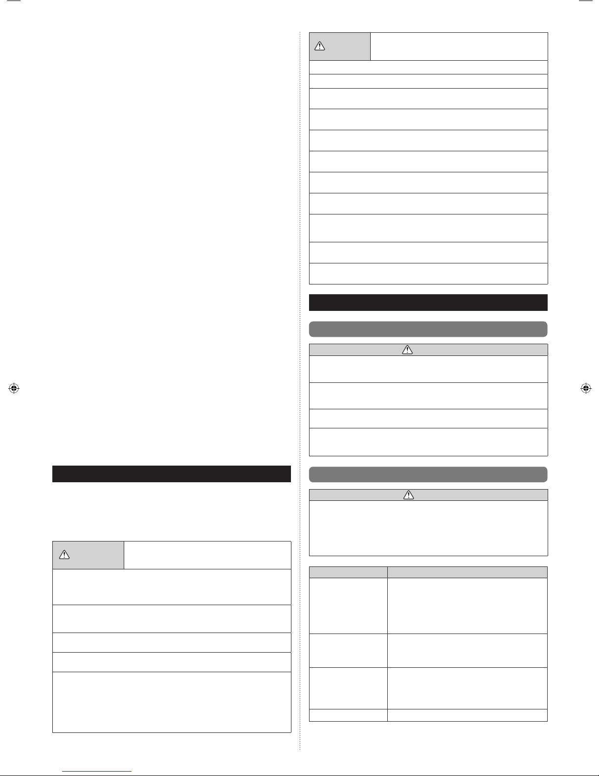
Tool name Changes
Gauge manifold
The pressure in the refrigerant system is extremely high
and cannot be measured with a conventional gauge.
To prevent erroneous mixing of other refrigerants,
the diameter of each port has been changed. It is
recommended to use a gauge manifold with a high
pressure display range of –0.1 to 5.3 MPa and a low
pressure display range of –0.1 to 3.8 MPa.
Charging hose
To increase pressure resistance, the hose material and
base size were changed.
(The charging port thread diameter for R410A is 1/2 UNF
20 threads per inch.)
Vacuum pump
A conventional vacuum pump can be used by installing a
vacuum pump adapter.
Be sure that the pump oil does not backflow into the
system. Use one capable for vacuum suction of
–100.7 kPa (5 Torr, –755 mmHg).
Gas leakage detector
Special gas leakage detector for R410A refrigerant.
INSTALLATION MANUAL
PART NO. 9381279005
VRF system DX-kit
Contents
1. SAFETY PRECAUTIONS .........................................................................................1
2. ABOUT THIS PRODUCT .......................................................................................... 1
2.1. Precautions for using R410A refrigerant ............................................................1
2.2. Special tool for R410A ........................................................................................ 1
2.3. Accessories ........................................................................................................2
2.4. Optional parts .....................................................................................................3
3. PRODUCT SELECTION ...........................................................................................3
3.1. Product Lineup ...................................................................................................3
3.2. System Design ...................................................................................................3
4. INSTALLATION WORK ............................................................................................4
4.1. Selecting an installation location ........................................................................4
4.2. Installation dimensions .......................................................................................4
4.3. Installing the unit .................................................................................................4
5. PIPE INSTALLATION ............................................................................................... 6
5.1. Selecting the pipe material .................................................................................6
5.2. Pipe requirement ................................................................................................6
5.3. Bending pipes ..................................................................................................... 6
5.4. Pipe connection ..................................................................................................6
5.5. Installing heat insulation .....................................................................................7
6. MOUNTING THERMISTORS ....................................................................................7
7. ELECTRICAL WIRING..............................................................................................7
7.1. Electrical requirement ......................................................................................... 8
7.2. Wiring method ....................................................................................................8
7.3. Unit wiring ........................................................................................................... 8
7.4. Connection of wiring .........................................................................................10
7.5. External input and external output (Optional parts) ..........................................12
8. FIELD SETTING ......................................................................................................15
8.1. Setting the address ...........................................................................................15
8.2. Dip switch setting .............................................................................................. 16
8.3. Function setting ................................................................................................16
9. TEST RUN ...............................................................................................................17
9.1. Test run using Outdoor unit (PCB) ...................................................................17
9.2. Test run using remote controller ....................................................................... 17
10. CHECK LIST (Example) ......................................................................................... 17
11. ERROR CODES ...................................................................................................... 17
12. OPERATIONS .........................................................................................................18
12.1. Analog external inputs ....................................................................................18
Page 3
En-2
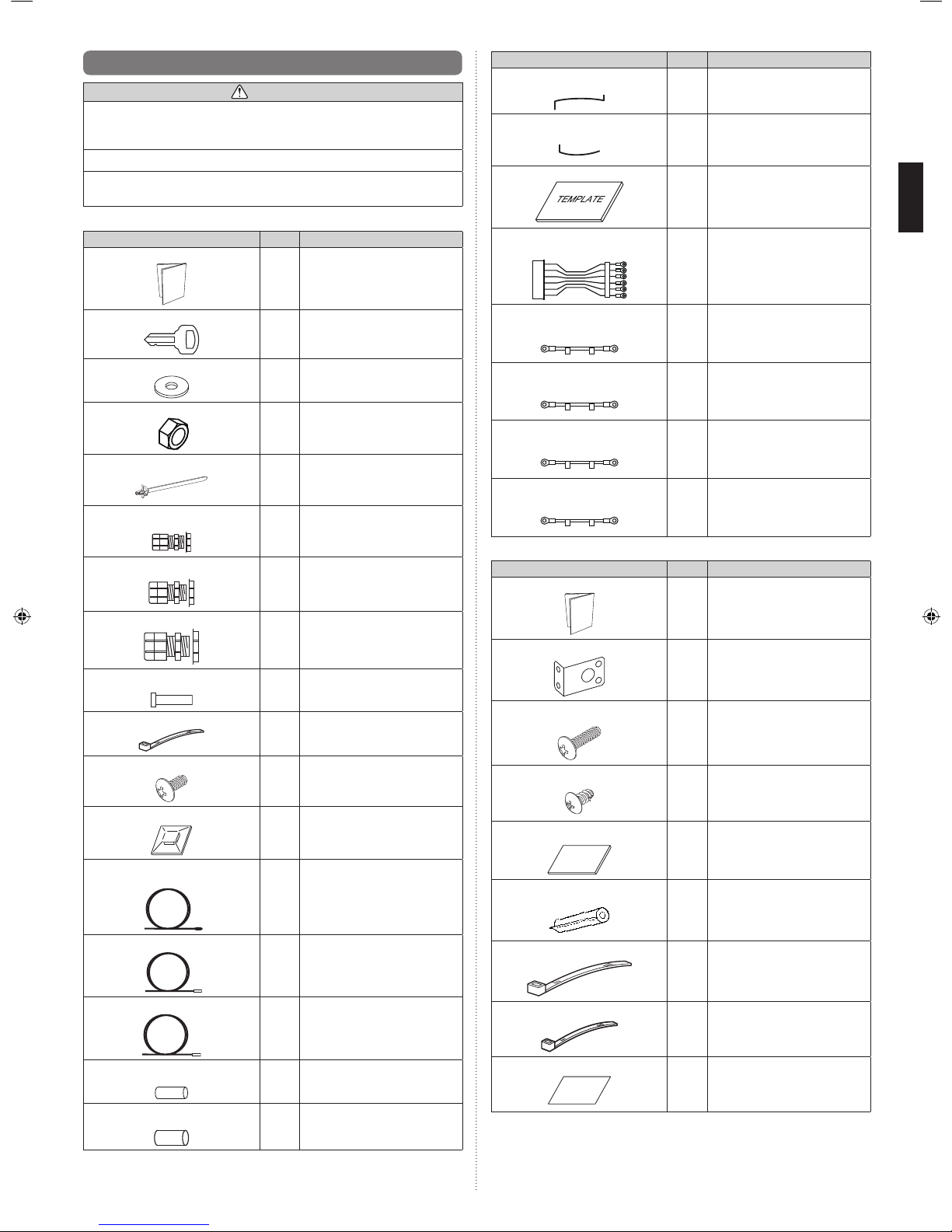
2.3. Accessories
WARNING
For installation purposes, be sure to use the parts supplied by the manufacturer or
other prescribed parts. The use of non-prescribed parts can cause serious accidents
such as the unit falling, water leakage, electric shock, or fi re.
The following installation parts are furnished. Use them as required.
Keep the Installation Manual in a safe place and do not discard any other accessories
until the installation work has been completed.
(1) Control unit Accessories
Name and Shape Q’ty Application
Installation Manual
1
(This book)
Key
2
For the door of control unit
Sealing washer
3
For mounting the control unit to the
wall Waterproof specifications
Nuts (M8)
3
For mounting the control unit to the
wall
Cable ties (with stopper)
19
For securing the cables
Cable gland (M10)
4
For cable holes
Cable gland (M16)
5
For cable holes
Cable gland (M20)
1
For cable holes
Blind bar
5
For mounting when not passing the
cable through the cable gland
Cable tie
3
For securing the optional remote
controller cable
Screw (M4×L6 mm)
3
For mounting the optional remote
controller
Cable tie mount
2
For securing the optional remote
controller cable
Thermistor
(Inlet air and Outlet air)
2
For measuring the room
temperature
Thermistor (Label: GAS)
1
For measuring the gas pipe
temperature
(For gas pipes)
Thermistor (Label: LIQ)
1
For measuring the liquid pipe
temperature
(For liquid pipes)
Thermistor holder pipe
(Small)
1
For mounting the thermistor
Thermistor holder pipe
(Large)
1
For mounting the thermistor
Name and Shape Q’ty Application
Thermistor spring (For small thermistor
holder pipe)
1
For mounting the thermistor
Thermistor spring (For large thermistor
holder pipe)
1
For mounting the thermistor
Template
1
For installing the control unit
Connection cable 1
[Label : 32,33,35,37,39,41]
1
For external output
Connection cable 2
[Label : 32,34]
1
For external output
Connection cable 3
[Label : 34,36]
1
For external output
Connection cable 4
[Label : 36,38]
1
For external output
Connection cable 5
[Label : 38,40]
1
For external output
(2) EEV unit Accessories
Name and Shape Q’ty Application
Installation Manual
1 ―
Secure fitting
4
For mounting the EEV unit to the
wall, or stacking multiple EEV units
Tapping Screw L (M4×L16)
8
For mounting the EEV unit to the
wall
Tapping Screw S (M4×L10)
8
For stacking multiple EEV unit
Rubber sheet
2
For mounting pipe joints
Pipe heat insulations
2
For mounting pipe joints
cable tie (Large)
4
For securing heat insulations
cable tie (Medium)
1
For securing cables
Seal
2
For pasting unused piping holes
Page 4
En-3
2.4. Optional parts
The following options are available.
When installing, refer to the installation manual of each optional part.
Connectable Peripheral Devices
Model Name Notes
Wired Remote Controller UTY-RNKY *1, *2
Wired Remote Controller UTY-RNRY *1, *2
Wireless Remote Controller
(IR receiver unit)
UTY-LNHY
(UTB-YWC)
*2
Group Remote Controller
(via network converter)
UTY-CGGY
(UTY-VGGXZ1)
*2
Touch Panel Controller UTY-DTGY *2
Central Remote Controller UTY-DCGY *2
Network Convertor for LONWORKS® UTY-VLGX *2
BACnet® Gateway UTY-ABGX *2
System Controller UTY-APGX *2
System Controller Lite UTY-ALGX *2
Service Tool UTY-ASGX *2
Web Monitoring Tool UTY-AMGX *2
Separation Tube (For EEV unit 2 connections) UTP-LX180A —
*1 Remote controller groups cannot be connected using DX-kits or other indoor units.
*2 If controlling using “external input and output” analog inputs from an external controller
(DDC), operations from the controllers described above are disabled.
3. PRODUCT SELECTION
• Failure to observe the selection conditions described below will affect the outdoor unit
service life and operational reliability.
• When selecting air handling unit, it must be designed for R410A refrigeration.
3.1. Product Lineup
(1) Product Lineup
Unit Name Model Name Environment specifi cations
Control unit UTY-VDGX
• Temperature:
-20 to 46 °C
• Humidity:
10 to 90% RH
(No condensation)
EEV unit
UTP-VX30A
UTP-VX60A
UTP-VX90A
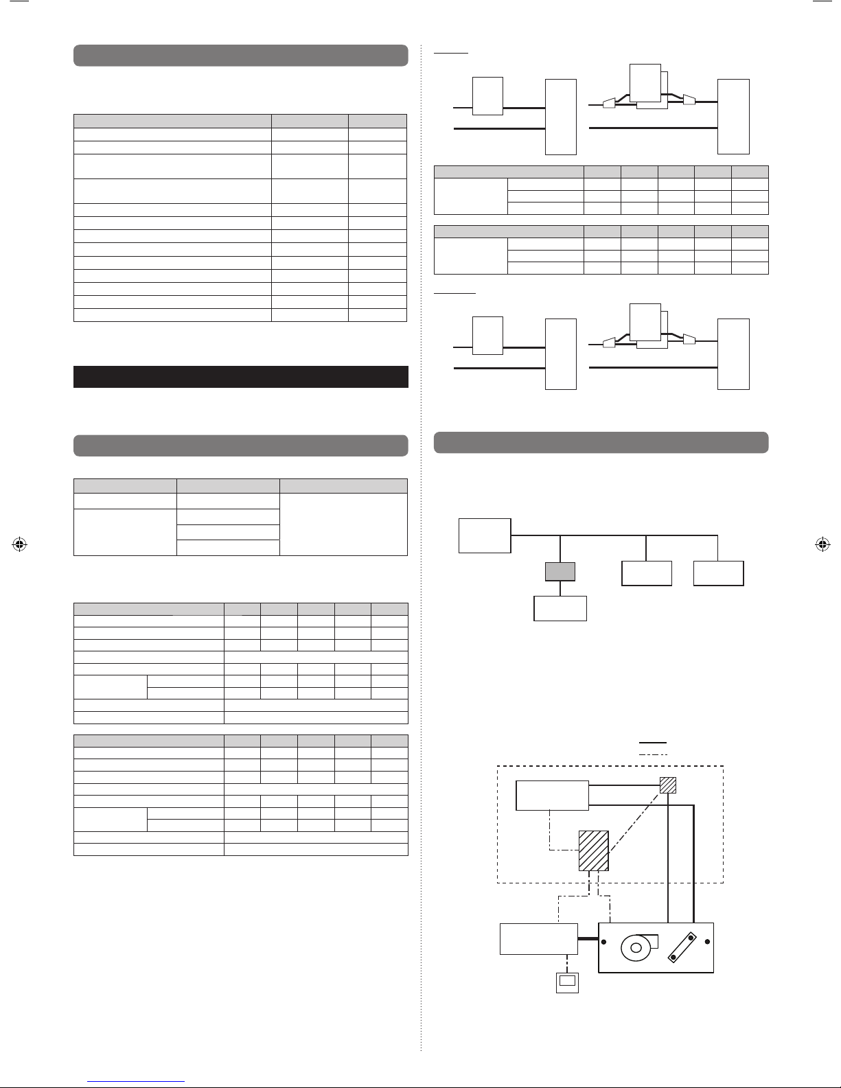
(2) EEV unit Selection
• The EEV unit is selected according to the capacity class conditions.
• If the capacity class is 40 kW or 50 kW, 2 EEV units are connected (in parallel).
Capacity Class (kW) 5.0 6.3 8.0 10.0 12.5
EEV unit model No.
30 30 30 60 60
Cooling capacity (kW)
5.6
6.3 8 10 12.5
Heating capacity (kW)
6.3
7.1 9 11.2 14
Heat exchanger capacity
Refer to the Design &Technical manual.
Airfl ow rate (Reference) (m3/h)
1,060
1,200 1,520 1,600 2,000
Capacity range Cool (kW) 5.1~5.9 6.0~7.1 7.2~9.0 9.1~11.1
11.2~13.2
Heat (kW) 5.7~6.7 6.8~8.0 8.1~10.0
10.1~12.4 12.5~15.0
Evaporation temperature Refer to the Design &Technical manual.
Condensation temperature Refer to the Design &Technical manual.
Capacity Class (kW) 14.0 20.0 25.0 40.0 50.0
EEV unit model No.
60 90 90 90+90 90+90
Cooling capacity (kW)
14
22.4 25 40 50.4
Heating capacity (kW)
16
25 28 45 56.5
Heat exchanger capacity
Refer to the Design &Technical manual.
Airfl ow rate (Reference) (m
3
/h)
2,240
3,560 4,000 6,400 8,000
Capacity range Cool (kW)
13.3~18.0 18.1~23.7 23.8~28.0 28.1~44.7 44.8~50.4
Heat (kW)
15.1~20.0 20.1~26.5 26.6~31.5 31.6~49.9 50.0~56.5
Evaporation temperature Refer to the Design &Technical manual.
Condensation temperature Refer to the Design &Technical manual.
Pipe size
(b)
(a)
(c)
(c)
(b)
(b)
(c)
(a)
(c)
(b)
Heat
Exchanger
Heat
Exchanger
Gas pipe Gas pipe
Liquid
pipe
Liquid
pipe
EEV
unit
EEV
unit
Capacity Class (kW) 5.0 6.3 8.0 10.0 12.5
Pipe size Gas (a) (mm) 15.88 15.88 15.88 15.88 19.05
Liquid (b) (mm) 9.52 9.52 9.52 9.52 9.52
Liquid (c) (mm) — ————
Capacity Class (kW) 14.0 20.0 25.0 40.0 50.0
Pipe size Gas (a) (mm) 19.05 22.2 22.2 28.58 28.58
Liquid (b) (mm) 9.52 12.7 12.7 12.7 15.88
Liquid (c) (mm) — — — 12.7 12.7
Pipe length
(a)
(d)
(c)
(f)
(e)
(b)
Heat
Exchanger
Heat
Exchanger
Gas pipe Gas pipe
Liquid
pipe
(a) ≤ 5 m (b) ≤ 2 m , (c) ≤ 2 m , (d) ≤ 2 m , (e) ≤ 2 m
(d) + (f) ≤ 5 m , (e) + (f) ≤ 5 m
Liquid
pipe
EEV
unit
EEV
unit
3.2. System Design
3.2.1. Basic Refrigerating System Confi guration
Using the DX-kit enables indoor units manufactured by other than Fujitsu general to be
used in the Fujitsu general refrigerant system.
DX-kit*
Outdoor unit
Indoor unit
Indoor unit Indoor unit
* DX-kit = Control unit + EEV unit
3.2.2. Basic DX-kit System Confi guration
(1) System Pattern 1
External controllers (DDC) not manufactured by Fujitsu general control the Fujitsu general
outdoor units and indoor units (refrigerant cycle devices, etc.) not manufactured by Fujitsu
general. With this system, control using a Fujitsu general VRF controller is not possible.
System Confi guration Diagram
Fujitsu general-approved devices
Outdoor unit
Indoor unit
Control unit
Liquid pipe
Gas pipe
Thermistor × 4
Wired remote
controller
External controller
not manufactured
by Fujitsu general
Control line
Piping
Wiring
EEV unit
For control line details, see “External Input and External Output”.
Page 5
En-4
If children under 10 years old may approach the unit, take preventive measures so
that they cannot reach the unit.
Take precautions to prevent the unit from falling.
(1) Install the DX-kit on a place having a suffi cient strength so that it withstands against
the weight of the DX-kit.
(2) Leave the space required to service the DX-kit.
(3) Install the unit where connection to the outdoor unit (or RB unit) is easy.
(4) Install the unit where the connection pipe can be easily installed.
(5) Install the unit where noise and vibrations are not amplifi ed.
(6) Take servicing, etc., into consideration and leave the spaces.
(7) Do not install the unit where it will be exposed to direct sunlight.
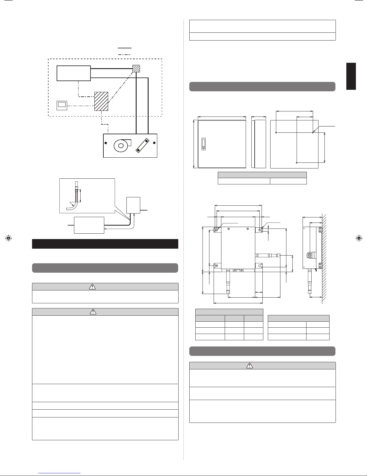
4.2. Installation dimensions
4.2.1. Control unit
400 120 134
306
3 × Ø10
(Unit: mm)
400
251
Weight of the Control unit (kg)
UTY-VDGX 10
4.2.2. EEV unit
EEV unit Dimensions
221
203
159
4 × Ø11
8 × Ø5
22 31
90
58
58(120)(127)
168
212.4(104)
29.2
182
14
22.2
(78)
231
A
B
36
(Unit: mm)
Connection pipe diameter (mm)
Model A B Weight of the EEV unit (kg)
UTP-VX30A 9.52 9.52 UTP-VX30A 2
UTP-VX60A 9.52 9.52 UTP-VX60A 2
UTP-VX90A 12.7 12.7 UTP-VX90A 2
4.3. Installing the unit
WARNING
Install the DX-kit in a location which can withstand a load of at least 5 times the weight
of the main unit and which will not amplify sound or vibration. If the installation location
is not strong enough, the DX-kit may fall and cause injuries.
If the job is done with the panel frame only, there is a risk that the unit will come loose.
Please take care.
Carrying in and installation of the unit should be performed by a suffi cient number
of people and with suffi cient equipment that is adequate for the weight of the unit.
Performing such work by an insufficient number of people or with inadequate
equipment could result in dropping of the unit or personal injury.
(2) Pattern 2
Fujitsu general remote controllers and control devices directly control Fujitsu general outdoor units and indoor units (refrigerant cycle devices, etc.) not manufactured by Fujitsu
general. A system confi guration example is shown below.
System Confi guration Diagram
Fujitsu general-approved devices
Outdoor unit
Indoor unit
Control unit
Liquid pipe
Gas pipe
Control line
Thermistor × 4
Wired remote
controller
Piping
Wiring
EEV unit
3.2.3. Pipe Conditions
EEV
unit
Heat
Exchanger
R
Straight pipe =
200 mm or more
Liquid pipe
Gas pipe
4. INSTALLATION WORK
Correct initial installation location is important because it is diffi cult to move unit after it is
installed.
4.1. Selecting an installation location
Decide the mounting position together with the customer as follows.
WARNING
Select installation locations that can properly support the weight of the DX-kit. Install
the units securely so that they do not topple or fall.
CAUTION
Do not install the DX-kit in the following areas:
• Area with high salt content, such as at the seaside. It will deteriorate metal parts,
causing the parts to fail or the unit to leak water.
• Area fi lled with mineral oil or containing a large amount of splashed oil or steam,
such as a kitchen. It will deteriorate plastic parts, causing the parts to fail or the unit
to leak water.
• Area that generates substances that adversely affect the equipment, such as sulfuric
gas, chlorine gas, acid, or alkali. It will cause the copper pipes and brazed joints to
corrode, which can cause refrigerant leakage.
• Area that can cause combustible gas to leak, contains suspended carbon fi bers or
fl ammable dust, or volatile infl ammables such as paint thinner or gasoline. If gas
leaks and settles around the unit, it can cause a fi re.
• Area where animals may urinate on the unit or ammonia may be generated.
Do not use the unit for special purposes, such as storing food, raising animals,
growing plants, or preserving precision devices or art objects.
It can degrade the quality of the preserved or stored objects.
Do not install where there is the danger of combustible gas leakage.
Do not install the unit near a source of heat, steam, or fl ammable gas.
Install the DX-kit, power supply cable, transmission cable, and remote controller cable
at least 1 m away from a television or radio receivers. The purpose of this is to prevent
TV reception interference or radio noise. (Even if they are installed more than 1 m
apart, you could still receive noise under some signal conditions.)
Page 6
En-5
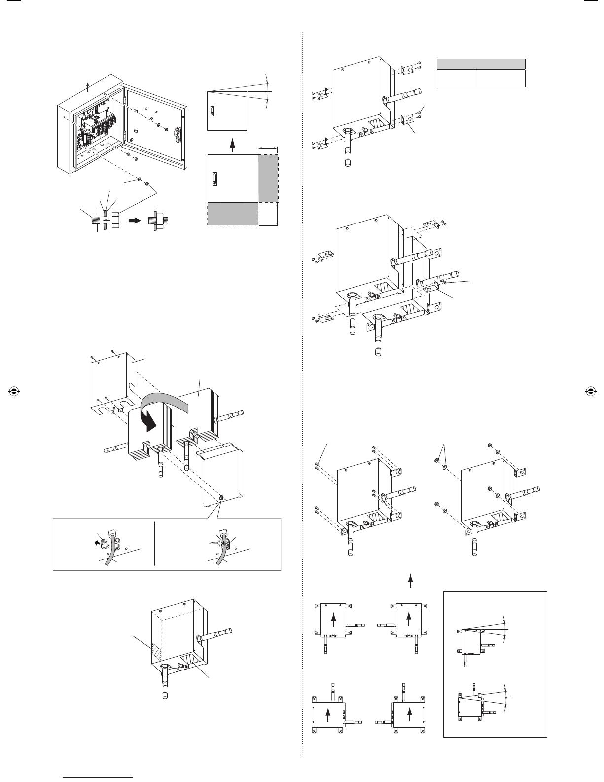
4.3.2.3. Mounting Secure Fittings (If Using 1 EEV unit)
(1) Use the 8 screws (accessories) to secure the secure fi ttings (accessories).
Secure fi tting (Accessories)
Screws M4×L10 (Accessories)
Tightening torque
M4 screw
0.8 to 2.8 Nm
(8 to 28 kgf·cm)
4.3.2.4. Mounting Secure Fittings (If Using 2 EEV units)
(1) If using 2 EEV units, stacking the 2 kits is recommended.
If stacking 2 EEV units, secure using the secure fi ttings (accessories) and screws
(accessories).
Secure fi tting (Accessories)
Screws M4×L10
(Accessories)
4.3.2.5. Installing EEV units
Mount the EEV unit to the wall.
Select the securing method according to the installation environment.
Method 1: Use the 8 screws (accessories) to secure the unit.
Method 2: Mount the 4 anchor bolts (fi eld supply) to the wall, and then secure the unit.
Screws M4×L16
(Accessories)
Method 1 Method 2
Nuts and washers
(Field supply)
Installable EEV unit orientations
A
AA
A
B
BB
B
Orient the arrow upwards
Installable both indoors and outdoors
Installable indoors only
(Cannot be installed outdoors)
EEV unit inclination limits
±10° or
less
±10° or
less
4.3.1. Installing the Control unit
• If installing outdoors, make sure to orient A upwards.
• Using a template (accessory) is recommended when positioning the holes for mounting
the control unit.
±5° or
less
Inclination limits
Sealing washers
(×3, Accessories)
M8 Nuts
(×3, Accessories)
A
A
Contorl
unit
200 mm or more
Service
space
200 mm or more
Service
space
Rubber inside the washer is contacted
tightly with the Control unit.
anchor
bolt
Rubber Steel
4.3.2. Installing the EEV unit
4.3.2.1. Changing Pipe Orientation
• EEV unit pipe orientation can be changed according to the installation conditions.
(1) Remove the 4 screws and remove the cover.
(2) Cut the cable tie fi xing the cable.
(3) Invert both the pipes and heat insulation.
(4) Pass the cable tie (accessory) through the cable clamp, and fi rmly secure the cable,
and then cut any unnecessary part of cable tie.
(5) Use the 4 screws to mount the cover.
Cable Cable
Cable clamp
Cable tie
Cable tie
(accessory)
(2)
(1), (5)
Cover
Heat insulation
(4)
(3)
4.3.2.2. Pasting Seals to the piping holes
Use the seals (accessories) to cover any unused piping holes.
Seal
(Accessories)
Seal
(Accessories)
Page 7
En-6
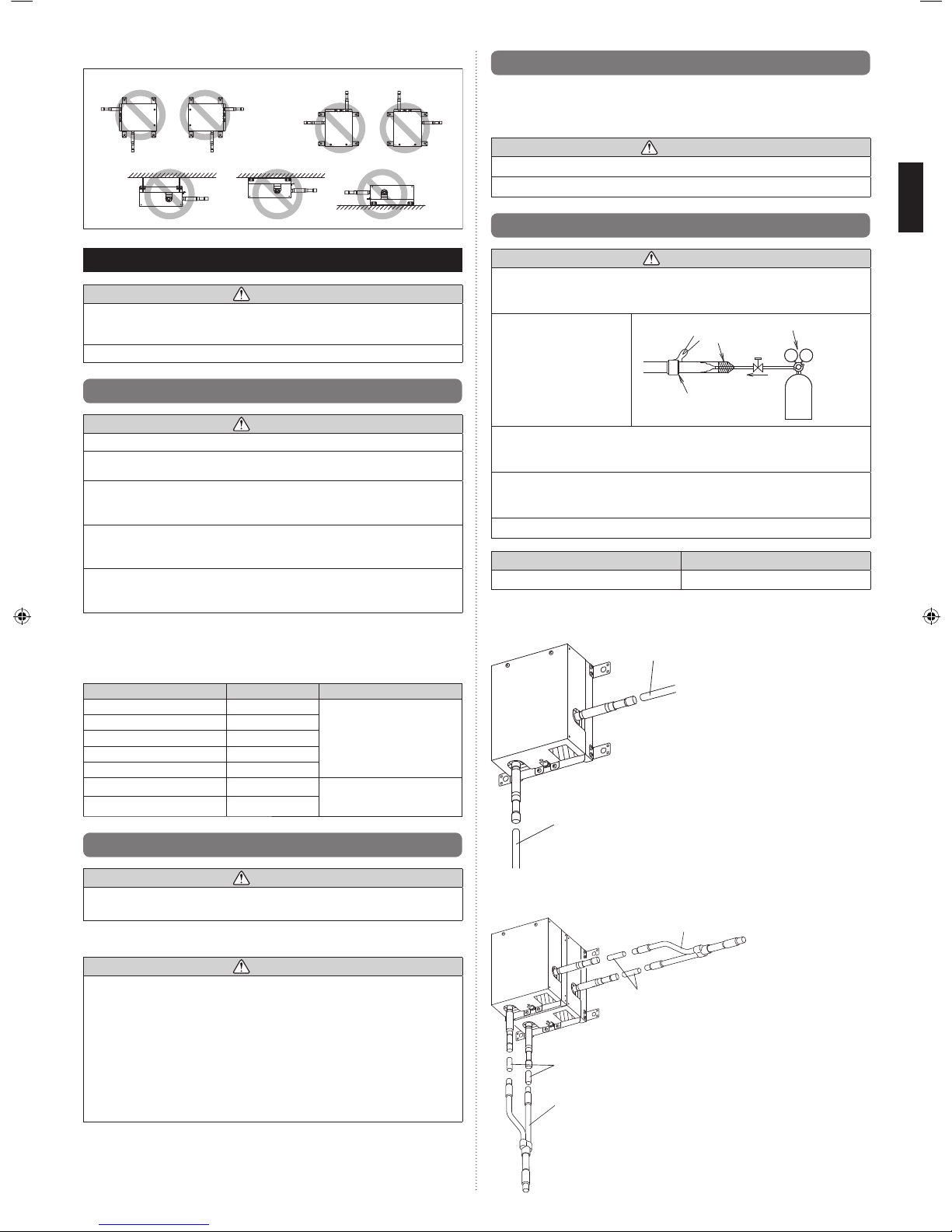
Prohibited EEV unit orientations
A
AA
A
B
BB
B
PROHIBITED
5. PIPE INSTALLATION
CAUTION
Be more careful that foreign matter (oil, water, etc.) does not enter the piping than with
refrigerant R410A models. Also, when storing the piping, securely seal the openings
by pinching, taping, etc.
While welding the pipes, be sure to blow dry nitrogen gas through them.
5.1. Selecting the pipe material
CAUTION
Do not use existing pipes from another refrigeration system or refrigerant.
Use pipes that have clean external and internal sides without any contamination which
may cause trouble during use, such as sulfur, oxide, dust, cutting waste, oil, or water.
It is necessary to use seamless copper pipes.
Material : Phosphor deoxidized seamless copper pipes
It is desirable that the amount of residual oil is less than 40 mg/10 m.
Do not use copper pipes that have a collapsed, deformed, or discolored portion
(especially on the interior surface). Otherwise, the expansion valve or capillary tube
may become blocked with contaminants.
Improper pipe selection will degrade performance. As an air conditioner using R410A
incurs pressure higher than when using conventional (R22) refrigerant, it is necessary
to choose adequate materials.
• Thicknesses of copper pipes used with R410A are as shown in the table.
• Never use copper pipes thinner than those indicated in the table even if they are
available on the market.
Thicknesses of Annealed Copper Pipes (R410A)
Pipe outside diameter [mm (in.)] Thickness [mm] Material
6.35 (1/4) 0.80
COPPER
JIS H3300 C1220T-O
or equivalent
9.52 (3/8) 0.80
12.70 (1/2) 0.80
15.88 (5/8) 1.00
19.05 (3/4) 1.20
22.22 (7/8) 1.00
COPPER
JIS H3300 C1220T-H
or equivalent
28.58 (1-1/8) 1.00
5.2. Pipe requirement
CAUTION
Refer to the Installation Manual of the outdoor unit for description of the length of
connecting pipe or for difference of its elevation.
• Use pipe with water-resistant heat insulation.
CAUTION
Install heat insulation around both the gas and liquid pipes. Failure to do so may
cause water leaks.
Use heat insulation with heat resistance above 120 °C. (Reverse cycle model only)
In addition, if the humidity level at the installation location of the refrigerant piping is
expected to exceed 70 %, install heat insulation around the refrigerant piping. If the
expected humidity level is 70 to 80 %, use heat insulation that is 15 mm or thicker and
if the expected humidity exceeds 80 %, use heat insulation that is 20 mm or thicker. If
heat insulation is used that is not as thick as specifi ed, condensation may form on the
surface of the insulation. In addition, use heat insulation with heat conductivity of
0.045 W/(m·K) or less (at 20 °C).
5.3. Bending pipes
• The pipes are shaped by your hands or pipe bender. Be careful not to collapse them.
• Do not bend the pipes in an angle more than 90°.
• When pipes are repeatedly bend or stretched, the material will harden, making it diffi cult
to bend or stretch them any more. Do not bend or stretch the pipes more than 3 times.
CAUTION
To prevent breaking of the pipe, avoid sharp bends.
If the pipe is bent repeatedly at the same place, it will break.
5.4. Pipe connection
CAUTION
If air or another type of refrigerant enters the refrigeration cycle, the internal pressure
in the refrigeration cycle will become abnormally high and prevent the unit from
exerting its full performance.
Apply nitrogen gas while
brazing the pipes. Nitrogen
gas pressure:
0.02 MPa (= pressure felt
sufficiently on the back of
your hand)
Pressure regulating valve
Cap
Nitrogen gas
Brazing area
If a pipe is brazed without applying nitrogen gas, it will create an oxidation fi lm.
This can degrade performance or damage the parts in the unit (such as the
compressor or valves).
Do not use fl ux to braze pipes. If the fl ux is the chlorine type, it will cause the pipes to
corrode. Furthermore, if the fl ux contains fl uoride, it will adversely affect the refrigerant
pipe system such as by degrading the refrigerant oil.
For brazing material, use phosphor copper that does not require fl ux.
Outer diameter of pipe
Connection Pipe (Liquid) 12.70 mm
Connect the EEV unit pipe to the connection pipe. Braze the connectors.
(a) Connecting 1 EEV unit
Connection pipe
(fi eld supply)
Connection pipe
(fi eld supply)
(b) Connecting 2 EEV units
If connecting 2 stacked EEV units, connect the special branch pipe (optional part).
Relay pipes: Outside dimensions Φ12.7 mm
(Field supply)
Relay pipes: Outside dimensions Φ12.7 mm
(Field supply)
Branch pipes
(Optional parts)
Branch pipes
(Optional parts)
Page 8
En-7
C: Inlet air thermistor/D: Outlet air thermistor
Install in a location where the effects of heat sources such as heat exchangers and heaters, etc., are minimized as far as possible.
CD
Inlet air thermistor
(Accessories)
Outlet air thermistor
(Accessories)
Air outletAir inlet
General indoor unit
7. ELECTRICAL WIRING
WARNING
Electrical work must be performed in accordance with this Manual by a person
certifi ed under the national or regional regulations. Be sure to use a dedicated circuit
for the unit. An insuffi cient power supply circuit or improperly performed electrical work
can cause serious accidents such as electric shock or fi re.
Before starting work, check that power is not being supplied to the all units.
Use the included connection cables and power cables or ones specified by the
manufacturer. Improper connections, insuffi cient insulation, or exceeding the allowable
current can cause electric shock or fi re.
For wiring, use the prescribed type of cables, connect them securely, making sure
that there are no external forces of the cables applied to the terminal connections.
Improperly connected or secured cables can cause serious accidents such as
overheating the terminals, electric shock, or fi re.
Do not modify the power cables, use extension cables, or use any branches in the
wiring. Improper connections, insufficient insulation, or exceeding the allowable
current can cause electric shock or fi re.
Match the terminal board numbers and connection cable colors with those of the
outdoor unit (or RB unit). Erroneous wiring may cause burning of the electric parts.
Securely connect the connection cables to the terminal board. In addition, secure the
cables with wiring holders. Improper connections, either in the wiring or at the ends of
the wiring, can cause a malfunction, electric shock, or fi re.
Always fasten the outside covering of the connection cable with the cable clamp. (If
the insulator is chafed, electric discharge may occur.)
Securely install the electrical box cover on the unit. An improperly installed electrical
box cover can cause serious accidents such as electric shock or fi re through exposure
to dust or water.
Install sleeves into any holes made in the walls for wiring. Otherwise, a short circuit
could result.
Install an earth leakage breaker. In addition, install the earth leakage breaker so that
the entire AC main power supply is cut off at the same time. Otherwise, electric shock
or fi re could result.
Always connect the earth (ground) cable.
Improper earthing (grounding) work can cause electric shocks.
Install the remote controller cables so as not to be direct touched with your hand.
Perform wiring work in accordance with standards so that the DX-kit can be operated
safely and positively.
Connect the connection cable fi rmly to the terminal board. Imperfect installation may
cause a fi re.
If the supply cable is damaged, it must be replaced by the manufacturer, its service
agent or similarly qualifi ed persons in order to avoid a hazard.
Take special precaution for connection to the external controller (DDC, fi eld supply).
Make sure the wiring for the external input and output signals is correct.
Miswiring of these cables could damage the entire system.
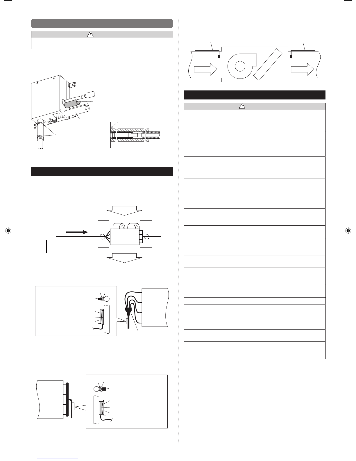
5.5. Installing heat insulation
CAUTION
After checking for gas leaks (refer to the Installation Manual of the outdoor unit),
perform this section. Failure to do so may cause water leaks.
Implement heat insulation as shown in the diagram below.
(1) Mount the rubber sheets (accessories).
(2) Mount the heat insulations (accessories). There should be no gaps between the
insulation and the product.
(3) Secure to a pipe using 2 cable ties.
(1) Butyl rubber sheets
(Accessories)
(2) Heat insulations
(Accessories)
(3) Cable ties
(Large, accessories)
No gap
• Perform the work in (1), (2) and (3) for the 2 pipes.
• For the heat insulation on the separation tube (Optional parts) used to connect 2 EEV
units ,refer to the installation manual of the separation tube.
6. MOUNTING THERMISTORS
• To prevent water from accumulating on top of the thermistor, orient the thermistor wires
downwards when mounting the thermistor.
• Make good contact between thermistor and air handling unit. Put the top of the thermistors on the air handling unit, this is the most sensitive point of the thermistor.
Mounting thermistors to general indoor units
A
C
D
B
EEV
kit
Refrigerant fl ow
during cooling
Air inlet
Air outlet
Heat
Exchanger
General indoor unit
A: Heat exchanger inlet pipe
Braze a thermistor holder pipe (Ø 6.35, accessory) in front of the distributor branch.
Use a thermistor spring (accessory) to tightly seal and secure the thermistor (Φ4, accessory) pipes.
(1) (2)
(3)
(1)
(2)
(3)
(1) Thermistor holder pipe
(Ø 6.35 mm)
(2) Thermistor (Ø 4 mm)
(3) Thermistor spring
Distributor
Heat
Exchanger
* Attach this thermistor in a location where the evaporating temperature can be detected
during cooling operation.
B: Heat exchanger outlet pipe
Braze a thermistor holder pipe (Ø 9.53, accessory) to the heat exchanger outlet pipe.
Use a thermistor spring (accessory) to tightly seal and secure the thermistor (Ø6, accessory) pipes.
(1)
(1)
(2)
(3)
(2)
(3)
(1) Thermistor holder pipe
(Ø 9.53 mm)
(2) Thermistor (Ø 6 mm)
(3) Thermistor spring
Heat Exchanger
Page 9

En-8
CAUTION
Earth (Ground) the unit.
Do not connect the earth (ground) cable to a gas pipe, water pipe, lightning rod, or a
telephone earth (ground) cable.
Improper earthing (grounding) may cause electric shock.
Do not connect power supply cables to the transmission or remote controller terminals,
as this will damage the product.
Never bundle the power supply cable and transmission cable, remote controller cable
together.
Separate these cable by 50 mm or more.
Bundling these cables together will cause miss operation or breakdown.
When handling PCB, static electricity charged in the body may cause malfunction of
the PCB. Follow the cautions below:
• Establish an earth (ground) for the DX-kit and outdoor units and peripheral devices.
• Cut power (breaker) off.
• Touch metal part of the DX-kit for more than 10 seconds to discharge static
electricity charged in the body.
• Do not touch terminals of parts and patterns implemented on PCB.
7.1. Electrical requirement
• The following breaker specifi cations apply only to connections for Fujitsu general indoor
units, RB units, and DX-kits.
• Do not simultaneously connect Fujitsu general devices and non-Fujitsu general devices
to the same breaker. In using non-Fujitsu general devices, follow the specifi cations for
that device.
Voltage rating 230 V
Operating range 198 to 264 V
• Select the power cable type and size in accordance with relevant local and national
regulations.
• Specifi cations for local wiring power cord and branch wiring are in compliance with local
code.
• Max. wire length: Set a length so that the voltage drop is less than 2%. Increase the wire
diameter when the wire length is long.
Refer to the table for the breaker specifi cations of each installation condition. Perform
the power crossover wiring within the range of the same refrigerant system. When the
crossover wiring is done, make a connection for DX-kits to satisfy conditions A and B
below.
A. Current breaker requirements
Model MCA MFA
UTY-VDGX 0.096 A 20 A
MCA: Minimum Circuit Ampacity
MFA: Main Fuse Ampacity
When the power crossover wiring is done, make it so that the total of the MCA of the
connected DX-kits ,RB units ,and indoor units does not exceed the 15 A. For indoor unit
MCA and RB unit MCA, refer to the indoor unit and RB unit installation manual.
If the capacity of connected DX-kits ,RB units ,and indoor units exceeds the upper limit,
either add breakers or use a breaker with a greater capacity.
B. Earth leakage breaker requirements
Breaker capacity
* Maximum connectable DX-kits, “indoor
units + DX-kits”, or “indoor units + RB
units + DX-kits”
30 mA, 0.1 sec or less 44 or less **
100 mA, 0.1 sec or less 45 to 128
* Heat pump type: indoor units, Heat recovery type: indoor units and RB units.
** If the total number of units connected to the breaker exceeds 44, either add a 30mA
breaker, or use breakers with a greater capacity.
7.1.1. Cable specifi cations
For cable selections, see the "Connection of wiring" chapter below.
7.2. Wiring method
EXAMPLE
Outdoor unit or RB unit *1
DX-kit (Control unit)
Transmission
X1,X2: Transmission
Y1,Y2,Y3: Remote controller
External interface
terminal *3
Indoor unit
Remote
controller
Remote controller
Power supply
Power supply Power supply
Breaker Breaker
*2
*2
*1: When connecting to the Heat Recovery System, refer to the installation manual of the
RB unit.
*2: When connecting the 2-wire type remote controller, Y3 is not used.
*3: For the external interface terminal, refer to "7.4. Connection of wiring".
(Crossover wiring of power supply)
Breaker
DX-kit (Control unit)
Power supply
Pull box
Pull box
Power supply
Power supply Power supply
Indoor unit Indoor unit
7.3. Unit wiring
• Before attaching the cable to terminal block.
7.3.1. Power supply cable and Drain pump signal cable
Adjust the length of power supply cable to avoid excessive tension with referring fi gure
below.
Power supply cable
Earth (Ground)
cable
20 mm
30 mm
Drain pump signal cable
Decide the peeling length of the covering for the drain pump signal cable according to the
conditions for connecting to the terminal.
Page 10

En-9
A. For solid core wiring
(1) To connect the electrical terminal, follow the below diagram and connect after looping
it around the end of the cable.
(2) Use the specifi ed cables, connect them securely, and fasten them so that there is no
stress placed on the terminals.
(3) Use an appropriate screwdriver to tighten the terminal screws. Do not use a
screwdriver that is too small, otherwise, the screw heads may be damaged and
prevent the screws from being properly tightened.
(4) Do not tighten the terminal screws too much, otherwise, the screws may break.
(5) See the table for the terminal screw tightening torques.
(6) Please do not fi x 2 power supply cables with 1 screw.
Strip 25 mm
Loop
Screw with
special washer
Screw with
special washer
Cable end
(Loop)
Cable
Cable
Terminal block
Cable end (Loop)
WARNING
When using solid core cables, do not use the ring terminal. If you use the solid core
cables with the ring terminal, the ring terminal’s pressure bonding may malfunction
and cause the cables to abnormally heat up.
B. For strand wiring
(1) Use ring terminals with insulating sleeves as shown in the fi gure below to connect to
the terminal block.
(2) Securely clamp the ring terminals to the cables using an appropriate tool so that the
cables do not come loose.
(3) Use the specifi ed cables, connect them securely, and fasten them so that there is no
stress placed on the terminals.
(4) Use an appropriate screwdriver to tighten the terminal screws. Do not use a screw-
driver that is too small, otherwise, the screw heads may be damaged and prevent the
screws from being properly tightened.
(5) Do not tighten the terminal screws too much, otherwise, the screws may break.
(6) See the table for the terminal screw tightening torques.
(7) Please do not fi x 2 power supply cables with 1 screw.
Sleeve
Strip 10 mm
Screw with
special washer
Screw with special
washer
Ring terminal
Cable
Terminal block
Cable
Ring terminal
Ring
terminal
WARNING
Use ring terminals and tighten the terminal screws to the specifi ed torques, otherwise,
abnormal overheating may be produced and possibly cause heavy damage inside the
unit.
Tightening torque
M4 screw
(Power supply/L, N, GND)
1.2 to 1.8 N·m
(12 to 18 kgf·cm)
7.3.2. Transmission cable, Remote controller cable and
External interface cable
Transmission cable
Shielded cable
(no fi lm)
25 mm
40 mm
Remote controller cable
25 mm
For 3-wire type
25 mm
For 2-wire type
External interface cable
Decide the peeling length the covering for the external interface cable according to the
conditions for connecting to the terminal.
Fig. A
GOOD PROHIBITED
Different diameter Connect to 1 side
WARNING
Tighten the terminal screws to the specifi ed torques, otherwise, abnormal overheating
may be produced and possibly cause heavy damage inside the unit.
Tightening torque
M3 screw
(Transmission/X1, X2)
(Remote controller/ Y1, Y2, Y3)
0.5 to 0.6 N·m
(5 to 6 kgf·cm)
CAUTION
To peel the fi lm from the lead cable, use a dedicated tool that will not damage the
conductor cable.
When installing a screw on the terminal block, do not cut the cable by overtightening
the screw. On the other hand, an undertightened screw can cause faulty contact, which
will lead to a communication failure.
Page 11

En-10
7.4. Connection of wiring
7.4.1. Terminal Explanation and Cable Holes
• Only one cable can be passed through each cable hole. To pass multiple cables
through a single cable hole, use a (fi eld supply) multi-conductor cable with more wires,
and bundle multiple cables into one.
• Maximum length of cable is 10 m. (recommended value, Except "P1" and "TR1")
TH1
TH2
TH3
TH4
EV1
EV2
EX1
EX2
EX3
EX4
EX6
EX7
EX5
EX8
EX9
EX10
P1
D1
TR1
R1
·Power supply terminal
·Drain pump signal terminal
·Transmission terminal
·Remote controller terminal
·External interface terminal
Cable holes with mounted cable glands (accessories)
Hole No.
Cable gland
type
Diameter
(mm)
Insertable cable
dimensions (mm)
H2 Large Φ20.0 Φ6 to 12
H5, H6, H7, H9, H10 Medium Φ16.2 Φ4 to 8
H1, H3, H4, H8 Small Φ10.2 Φ3 to 6
H1
H2
H3
H5
H4
H8
H9
H10
H6 H7
Terminal
No.
Terminal Name Hole No. Connection
Recommended
cable size
(mm2)
Cable type Specifi cations
P1 POWER SUPPLY H2 Power supply 2.5 (AWG14) Type245 IEC57 or
equivalent
1ø 50 Hz 198 to 264 V
2 Cable + earth (ground)
TR1 TRANSMISSION H3 Transmission line 0.33 (AWG22) LONWORKS compatible
cable
22 AWG LEVEL 4 (NEMA)
non-polar 2 core, twisted
pair solid core diameter
0.65 mm
R1 REMOTE CONTROLLER H4
2-wire type remote controller
0.33 to 1.25
(AWG22 to 16)
Sheathed PVC cable Non polar 2 core
3-wire type remote controller 0.33 (AWG22) Sheathed PVC cable Polar 3 core
D1 DRAIN PUMP H1 Drain pump 0.5 (AWG20) Type245 IEC57 or
equivalent
―
T1 THERMISTOR (GAS) H5 Thermistor mounted to the gas
pipe
0.33 (AWG22) Sheathed PVC cable Relay the multi-conductor
cable, and pass it through
the designated hole.
T2 THERMISTOR (LIQUID) Thermistor mounted to the liquid
pipe
T3 THERMISTOR (INLET AIR) Thermistor mounted to the inlet
T4 THERMISTOR (OUTLET AIR) Thermistor mounted to the outlet
EV1 EEV1 1 - Red
2 - Brown
3 - Black
4 - Green
5 - Yellow
6 - White
H9 Electronic expansion valve 1 0.33 (AWG22) Sheathed PVC cable ―
EV2 EEV2 H10 Electronic expansion valve 2 0.33 (AWG22) Sheathed PVC cable Use the electronic
expansion valves only
when two units are
connected
EX1 ON/OFF SIGNAL
(OUTPUT)
External output
/ Digital
H6 External controller 0.33 (AWG22) Sheathed PVC cable
―
EX2 ERROR SIGNAL
(OUTPUT)
External output
/ Digital
EX3 FAN SIGNAL External output
/ Digital
EX4 DEFROST SIGNAL External output
/ Digital
EX5 THERMOSTAT ON/OFF
SIGNAL
External output
/ Digital
EX6 ON/OFF SIGNAL (INPUT) External input
/ Digital
H7 External controller 0.33 (AWG22) Sheathed PVC cable ERROR SIGNAL
OFF(Open)= Error
ON(Short)= Normal
EX7* ERROR SIGNAL *
(INPUT)
External input
/ Digital
The factory default is shorted between the
terminals by the cables.
EX8 COOL/HEAT SIGNAL External input
/ Digital
EX9 ANALOG SIGNAL External input
/ Analog
EX10 FLOAT SW SIGNAL External input
/ Digital
H8 Float switch mounted to the heat
exchanger
0.33 (AWG22) Sheathed PVC cable
―
EX7*: The factory default is shorted between the terminals by the cables. If there is a malfunction with an external device, using this external input is recommended in order to protect the
refrigerant system.
Page 12

En-11
7.4.2. Connecting the Cables
CAUTION
Pay attention to the following during installation. Failure to do so may cause water
penetration damage.
• Use the attached waterproof cable gland.
• Multiple differently-shaped waterproof cable glands are attached, so make sure to
use the waterproof cable gland suited to the cable hole.
• Make sure to fi rmly secure the waterproof cable gland to the cable hole.
• When attaching the cable gland, using a tightening torque that is less than the
recommended value may cause water penetration. Using a tightening torque that is
more than the recommended value may cause damage to the cable gland.
(1) Connect the cable.
(i) As shown below, pass the cable through the cable hole on the bottom of the control
unit and through the cable gland (accessories), then connect the cable to the terminal block.
(ii) Attach the cable gland firmly to the
unit.
(iii) Attach the cable firmly to the cable
gland.
Terminal block Terminal block
(i) (ii) (iii)
A
B
Terminal block
(2) Secure the cable.
• Using power supply cables
Secure the cable using the cable clamp mounted inside the device.
• Using other than power supply cables
Secure the cable using the cable ties (With stopper, accessories).
Cable clamp
Cable ties
(With stopper,
accessories)
• Unused holes
Mount blind bars instead of cables to the cable glands.
(i) Insert the blind bar into the cable gland.
(ii) Firmly secure the blind bar to the cable gland.
(iii) Mount the cable gland to the hole, and secure fi rmly.
Blind bar
(i) (ii) (iii)
Tightening torque for cable gland
(recommended value)
AB
For M10 0.5 N·m 0.5 N·m
For M16 1.0 N·m 1.5 N·m
For M20 1.0 N·m 2.0 N·m
• Outdoor cable connections
(1) Thermistor cable connections
• Connect the thermistor cables to the relay multi-conductor cables as shown in the
diagram before passing through the hole.
• Make sure to use only weatherproof relay cables.
Terminal block
Thermistor
Relay cable
Cable connector
(2) Electronic expansion valve cable connections
Make sure to observe the following installation conditions
• Avoid locations in direct sunlight
• Avoid locations with wind and rain
• Avoid locations with water contact
Mount the wired remote controller to the inside of the control unit
(1) Processing the remote controller cable
(Unit: mm)
For 2-wire type remote controller (fi eld supply)
2510
Refer to the installation manual
of the remote controller.
750← To control unit To remote controller →
For 3-wire type remote controller (attached with the remote controller)
25
750
10
← To control unit To remote controller →
Refer to the installation manual
of the remote controller.
(2) Wiring the remote controller cable (door side)
See the wired remote controller installation manual for how to install the remote controller
and the wiring method. Further, as shown in the diagram below, pass and draw through
the remote controller cable from the case to the cable hole at the back of the case.
(Unit: mm)
50
150
Remote controller cable Back side of the door
Fixed position of the
remote controller
Earth (ground)
cable
Cable tie mounts
(Accessories)
Cable ties
(Accessories)
Cable tie (Accessories)
Bundle the remote
controller cable together
with the ground cable.
Screws M4×L6
(Accessories)
Remote
controller
cable
Rear case of the
remote controller
Page 13

En-12
(3) Wiring the remote controller cable (device side)
Y1 Y2 Y3Y1 Y2
Non-polar
*1
Red
White
Black
For 2-wire type For 3-wire type
Remote controller cable
Cable tie (Accessories)
*1) If you connect the remote controller cable to the terminal Y3, 2-wire type remote con-
troller does not work.
(4) Set the DIP switch according to the type of remote controller used.
Factory setting : 2WIRE
DIP switch
(SW1)
• When using the wired remote controller, if the temperature drops below 0°C, the LCD
display may become dim, the response may become slower, and the time accuracy of
the clock will be lost.
7.5. External input and external output (Optional
parts)
7.5.1. Digital external inputs
• Select either the apply voltage method or dry contact method for digital external inputs.
• Both types of terminals cannot be used simultaneously.
• Float witch signal is compatible with the dry contact method only.
Switch connectors as shown in the table below according to the method selected.
Terminal name
PCB connector (*: Factory setting)
Apply voltage Dry contact
ON/OFF SIGNAL
(INPUT)
CNA01 CNA02*
ERROR SIGNAL
(INPUT)
CNA06 CNA07*
COOL / HEAT SIGNAL CNA03 CNA04*
FLOAT SW SIGNAL Incompatible CNA05*
External input terminal
(Dry contact terminal)
External input terminal
(Apply voltage terminal)
External output terminal
CNA01
CNA04
CNA02
CNA07
CNB01
Controller PCB
CNA03
CNA06
• Use an external input and output cable with appropriate external dimension, depending
on the number of cables to be installed.
• The wire connection should be separate from the power cable line.
● Apply voltage terminal ([CNA01], [CNA03], [CNA06])
When a power supply must be provided at the input device you want to connect, use the
Apply voltage terminal ([CNA01], [CNA03], [CNA06]).
Power supply
DC 12 to 24 V
Load
resistance
Load
resistance
Load
resistance
Load
resistance
connected unit
Input 1Input 2Input 3
Control unit
Terminal
board
P.C.B.
CNA01
*b
*1
*a
*a
*a
*a
CNA06
CNA03
*1
Make the power supply DC12 to 24V. Select a power supply capacity with an ample
surplus for the connected load.
Do not impress a voltage exceeding 24V across pins 1-2, and 1-3.
*a The allowable current is DC 5mA to 10mA. (Recommended: DC5mA)
Provide a load resistance such that the current becomes DC10mA or less.
Select very low current use contacts (usable at DC12V, DC1mA or less).
*b The polarity is [+] for pin 1 and [-] for pin 2 and 3. Connect correctly.
Page 14
En-13
When connected to Apply voltage terminals of multiple DX-kits with a connected unit, be sure to
make a branch outside the DX-kit using a pull box, etc. as shown on below example.
Power supply
DC 12 to 24 V
Load
resistance
Load
resistance
connected unit
Input
device 2
Control unitControl unit Control unit
Input
device 1
Terminal
board
P.C.B.
CNA01
CNA01
CNA01
● Dry contact terminal ([CNA02], [CNA04] ,[CNA07])
When a power supply is unnecessary at the input device you want to connect, use the Dry
contact terminal ([CNA02], [CNA04], [CNA07]).
Control unit
Terminal
board
P.C.B.
*d
*d
*d
*c
Ch 4
*c
Ch 3
*c
Ch 1
*c
Ch 2
GND
CNA02
CNA04
CNA07
connected unit
*c Select very low current use contacts (usable at DC12V, DC1mA or less).
*d The wiring is different from Apply voltage terminals. Be suffi ciently careful when wiring.
When connected to Dry contact terminals of multiple indoor units with a connected unit,
insulate each indoor unit with relay, etc. as shown on below example.
Power supply for relay
Control unit
Control unit
Control unit
Input devi ce 2
Input devi ce 1
K1 - K6: Relay
(Device f or DC Current)
P.C . B
K1
P.C . B
P.C . B
K2
K3
K4
K5
K6
NOTE :
When connected to multiple indoor units directly, it will cause breakdown.
Operation behavior
● Input signal type
The input signal type can be selected.
It is switched by DIP switch on the indoor unit PCB.
Pulse
The widt h of pulse
must be lon ger than
200m sec.
Edge
DIP switc h [Set 2 -2] Input signal type
OFF (Factor y setting) Edge
ON Pulse
(1) ON/OFF SIGNAL (INPUT)
[For the “Edge” input method, function settings “60”=00]
Terminal block Input signal Command
ON/OFF SIGNAL
(INPUT)
Pin1 to Pin3
OFF → ON Operation
ON → OFF Operation stopped
[For the “Edge” input method, function settings “60”=01]
Terminal block Input signal Command
ON/OFF SIGNAL
(INPUT)
Pin1 to Pin3
OFF → ON Cooling operation
ON → OFF Operation stopped
[For the “Pulse” input method]
Terminal block Input signal Command
ON/OFF SIGNAL
(INPUT)
Pin1 to Pin2 OFF → ON Operation
Pin1 to Pin3 OFF → ON Stop
* The last command has priority.
* The indoor units within the same remote controller group operates in the same mode.
(2) ERROR SIGNAL (INPUT)
If an error signal is input, perform protection operation (Thermostat OFF mode).
Make sure to install so that the input signals during normal operation is always “ON”.
Terminal block Input signal Command
ERROR SIGNAL
(INPUT)
Pin1 to Pin2
ON Normal
OFF Error
(3) COOL/HEAT SIGNAL
Switch the operation mode (heating/cooling).
[“Edge” input method, func tion set tings “ 60”= 00]
Terminal block Input signal Command
COOL/HEAT
SIGNAL
Pin1 to Pin2
OFF → ON Heat
ON → OFF Cool
[“Edge” input method, function settings “60”=01]
Terminal block Input signal Command
COOL/HEAT
SIGNAL
Pin1 to Pin2
OFF → ON Heating operation
ON → OFF Operation stopped
Note
• In heat recovery system, HEAT/COOL switching during operation is disabled unless the
RB unit and DX-kit are connected in 1-to-1.
• If switching the operation mode directly from cooling to heating to cooling, set the
priority mode to “indoor unit priority” (*1), and set the DX-kit to “Administrative indoor
unit(or Master indoor unit) (*2)”. Making this setting when the DX-kit and the VRF for
another indoor unit are connected to the same refrigerant system will make the DX-kit
prioritize the operation mode, so be careful.
*1) For the setting methods, refer to the installation manual for the outdoor unit in V-II and
J-II systems, and refer to the installation manual for the RB unit in VR-II system.
*2) For the settings method, see the wired remote controller installation manual and this
installation manual.
(4) FLOAT SW SIGNAL
Check the drain status.
If the “ON” status continues for 3 mins. or more, decide a drainage error, and perform a
protection stop. (Thermostat OFF and FAN OFF mode) Further, turn OFF and ON the
power again to restore.
[“Edge” input only]
Connector Input signal Command
FLOAT SW SIGNAL Pin1 to Pin3
OFF → ON Protection operation
ON → OFF Normal
Page 15

En-14
7.5.2. Analog external inputs
Changing the voltage of the signals entered to “analog external inputs” enables you to set
either the operation temperature or the required operation performance.
If using this function, make the following DIP switch settings.
i) Set the “Analog external inputs ON/OFF” setting to “ON”.
ii) Set the control item (either the operation temperature or required operation perfor-
mance).
Connected unit
Connected
device
Control unit
(DX-kit)
Analog signal
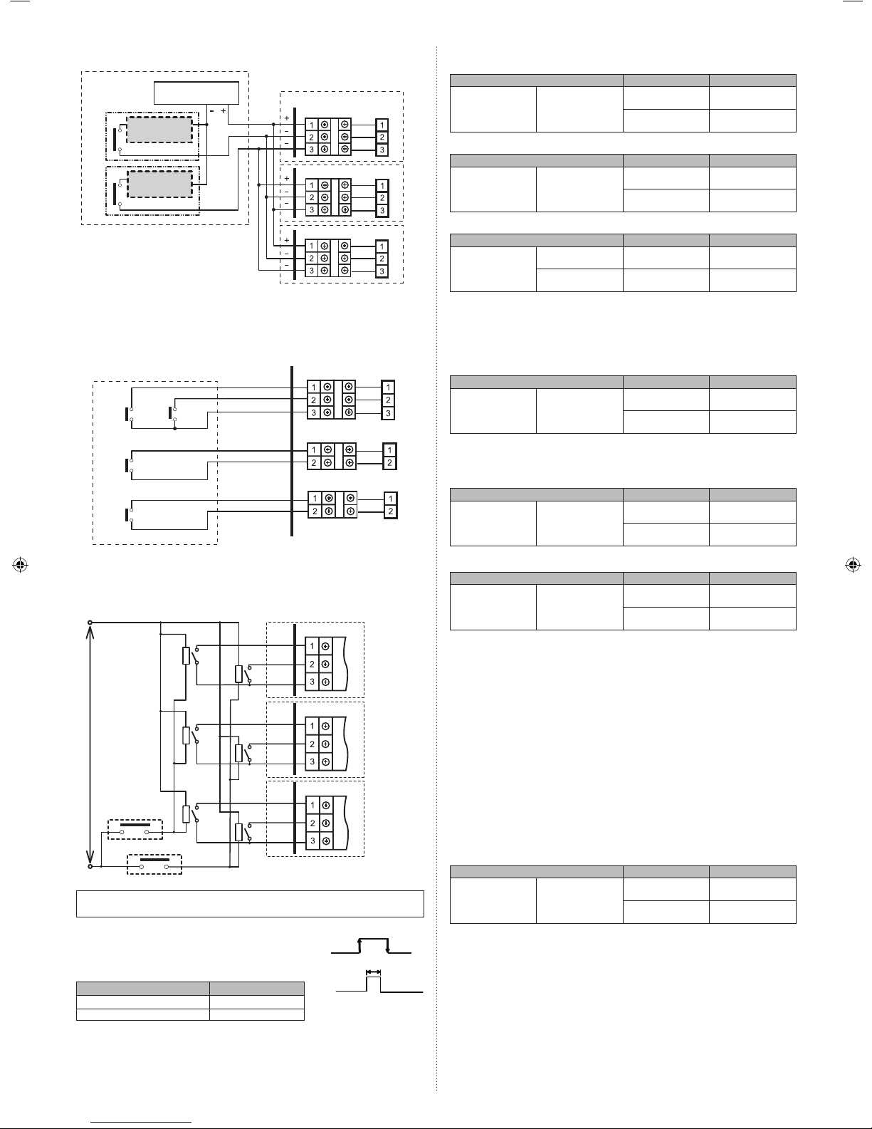
7.5.3. External output
No. Terminal block
Type-i Type-ii
Status
DX-kit
internal relay
status
DX-kit output
level
1 ON/OFF SIGNAL ON (Open) OFF Stop
OFF (Short) ON (DC12V) Operation
2 ERROR SIGNAL ON (Open) OFF Normal
OFF (Short) ON (DC12V) Error
3 FAN SIGNAL ON (Open) OFF FAN off
OFF (Short) ON (DC12V) FAN on
4 DEFROST SIGNAL ON (Open) OFF Normal
OFF (Short) ON (DC12V) Defrosting
5 THERMOSTAT
ON/OFF SIGNAL
ON (Open) OFF Thermostat Off
OFF (Short) ON (DC12V) Thermostat On
6 DRAIN PUMP
SIGNAL (*1)
OFF Drain pump Off
ON (AC 230 V) Drain pump On
● Selec t either of the following two power supply methods.
(Factory setting is Type-i)
Type-i • Using a power supply from other than the DX-kit (Connected unit, etc.)
• Usable tolerance voltages and currents: AC 220 to 240 V /1A max or
DC 30 V max /1A Max
Type-ii • Using a power supply from the DX-kit control unit
• Output voltage: Hi DC12V±2V, Lo 0 V / 50 mA max
• Use an external input and output cable with appropriate external dimension, depending
on the number of cables to be installed.
(1) Type-i: Using a power supply from other than the DX-kit (Connected unit, etc.)
1
2
3
4
5
6
Power supply
Terminal
Relay PC
board
Control unit (DX-kit)
Connected unit
Connected
device 1
Connected
device 2
Connected
device 3
Connected
device 4
Connected
device 5
Drain pump
PC board
Power supply
for drain pump
AC 220 to 240 V / 1A max
DC 30 V max / 1A max
When using a drain pump, connect relay that is
compatible with AC power supply. (fi eld supply)
• Precautions for Type-i
32
33
1
If connecting a dielectric load such as a relay
coil, etc., to the connected device, make sure to
add a surge protector circuit to the load side as
shown in the diagram.
Power supply
Connected device
Relay
Dielectric load
Surge protector circuit
Control unit (DX-kit)
Terminal
Relay PC
board
PC board
(2) Type-ii: Using a power supply from the DX-kit control unit
32
33
34
35
40
41
38
39
36
37
5
1
4
3
2
6
Terminal 12 VDC line
Control unit (DX-kit)
Connected unit
Connected
device 1
Connected
device 2
Connected
device 3
Connected
device 4
Connected
device 5
Drain pump
PC board
CNB01
Power supply
for drain pump
When using a drain pump, connect relay that is
compatible with AC power supply. (fi eld supply)
• If Type-ii is selected, change the wiring as shown in the diagram. (All cables used are
enclosed.)
(a1)
(b) (c) (d) (e)
(a2)
(a3)
(a4)
(a5)
(a6)
41403938373635343332
(a)
About the cable name and cable color
(a) Connection cable 1:
(a1) Brown, (a2) Red
(a3) Orange, (a4) Yellow
(a5) Green, (a6) Blue
(b) Connection cable 2:
Brown
(c) Connection cable 3:
Brown
(d) Connection cable 4:
Brown
(e) Connection cable 5:
Brown
CNB01 CN800
CN801 CN802 CNB01 Cable clamps
• If connecting an connection cables (accessories) to a terminal, make sure to
match the number of the label affi xed to the cable with the terminal number.
Page 16

En-15
8. FIELD SETTING
Dip switch
[LED1 indicator]
ON: Normal operation;
Flashing: Error
SET*-SW1
SET*-SW2
SET*-SW3
SET*-SW4
Dip switch
Rotary switch
IU AD ×10
IU AD ×1
REF AD ×1
REF AD ×10
RC AD ×1
LED1
SET2
SET3
SET4
SET1
Dip switch
CAUTION
Be sure to turn OFF the power before performing the fi eld setting.
8.1. Setting the address
8.1.1. Setting the indoor unit address and refrigerant circuit
address controlled by the DX-kit
(1) Setting automatic address
Set the rotary switch IU_AD,REF_AD to 0.
(For the advanced function settings, see the outdoor unit installation manual.)
(2) Setting manual address
Set the rotary switch IU_AD,REF_AD to the specifi ed value.
Manual address setting method
• If the receiver unit is attached, the indoor unit address and the refrigerant circuit
address can also be set up through the wireless remote controller.
CAUTION
Use an insulated screwdriver to set the DIP switches.
Setting
Setting
range
Type of switch
Indoor unit address
controlled by the
DX-kit *1
0 to 63
Setting
example
2
IU AD × 10 IU AD × 1
Refrigerant circuit
address *2
0 to 99
Setting
example
63
REF AD × 10
REF AD × 1
*1) Indoor unit address
Rotary switch (IU AD × 1)...Factory setting “0”
Rotary switch (IU AD × 10)...Factory setting “0”
When connecting multiple indoor units to 1 refrigerant system, set the address at IU
AD SW as shown in the Table A.
*2) Refrigerant circuit address
Rotary switch (REF AD × 1)...Factory setting “0”
Rotary switch (REF AD × 10)...Factory setting “0”
In the case of multiple refrigerant systems, set REF AD SW as shown in the Table A
for each refrigerant system.
Set to the same refrigerant circuit address as the outdoor unit.
• If working in an environment where the wireless remote controller can be used, the
addresses can also be set using the remote controller.
• If setting the addresses using the wireless remote controller, set the indoor unit
address and refrigerant circuit address to “00”.
(For information on setting using the wireless remote controller.)
Table A
Address
Rotary
Address
Rotary
Switch Setting Switch Setting
Refrigerant circuit
REF AD SW
Indoor unit
IU AD SW
× 10 × 1 × 10 × 1
000000
101101
202202
303303
404404
505505
606606
707707
808808
909909
10 1 0 10 0 0
11 1 1 11 1 1
12 1 2 12 1 2
.
.
.
.
.
.
.
.
.
.
.
.
.
.
.
.
.
.
99 9 9 63 6 3
Do not set the indoor unit address (IU AD SW) at 64 to 99.
It may result in failure.
8.1.2. Remote controller address
• Set this address if connecting a Fujitsu general remote controller.
• If using analog inputs, Fujitsu general remote controller operation will be disabled.
If using analog inputs , DX-kit cannot form the remote controller group.
i) 3-wire type
Rotary switch (RC AD SW)...Factory setting “0”
When connecting multiple indoor units to 1 standard wired remote controller, set the
address at RC AD SW in sequence from 0.
Setting Setting range Type of switch
Remote controller
address
0 to 15
Setting
example
0
RC AD
RC AD SW
0
RC AD SW
1
RC AD SW
0
RC AD SW
1
DX-kit DX-kit
Remote
controller
DX-kit cannot form the same remote controller
group as the indoor unit of other type.
DX-kit Indoor unit
RC AD SW 01234567
Address 01234567
RC AD SW 89ABCDEF
Address 8 9 10 11 12 13 14 15
ii) 2-wire type
Rotary switch (RC AD SW)...Factory setting “0”
Since the remote controller address settings are automatically confi gured, you do not
need to confi gure them.
If confi guring manually, it is necessary to confi gure both the indoor unit and the remote
controller.
For details, please refer to the remote controller manual.
Page 17

En-16
8.2. Dip switch setting
(1) Capacity settings of indoor units to be controlled
The capacity of indoor units to be controlled is set.
Indoor unit
capacity
Dip switch setting (*: factory setting)
SET1-1 SET1-2 SET1-3 SET1-4 SET2-1
5.0 kW * ON OFF ON OFF OFF
6.3 kW ON OFF ON OFF ON
8.0 kW ON ON ON OFF OFF
10.0 kW OFF ON ON OFF ON
12.5 kW OFF ON OFF ON OFF
14.0 kW ON ON OFF ON OFF
20.0 kW ON OFF ON ON OFF
25.0 kW OFF ON ON ON OFF
40.0 kW ON OFF OFF ON ON
50.0 kW OFF ON OFF ON ON
Not described
above
Settings prohibited
(2) Setting digital input signal methods
• Select either edge method or pulse method as the external inputs signal method.
DIP switch SET2-2 Digital input signals format
OFF (factory setting) Edge
ON Pulse
Make sure that SET2-3 and SET2-4 are always OFF.
(3) Analog external inputs method
• You can select the item to be controlled using analog external inputs from the external
controller (either “Operation temperature” or “Required operation performance”).
• Make the DIP switch SET3-1 settings before making the SET3-2 settings.
• Make sure to set a connection status that uses the external controller.
• If SET3-1 is ON, VRF device controls will be disabled.
(i) Analog external inputs ON/OFF
DIP switch SET3-1 Analog external inputs ON/OFF
OFF (factory setting) OFF
ON ON
(ii) Control items
• The items to be controlled are selected according to the device status that uses the
external controller.
DIP switch SET3-2 Control conditions
OFF (factory setting) Operation temperature
ON Required operation performance
(4) AC (air conditioning.) control settings
• Select the AC control format from either “outlet temperature control” or “inlet temperature
control”.
DIP switch SET3-3 Temperature control position
OFF (factory setting) Outlet temperature control
ON Inlet temperature control
Make sure that SET3-4 is always OFF.
(5) RB unit bypass circuit feasibility
• If connecting the RB unit and a general indoor unit 1-to-1 in the heat recovery system
unit, confi gure a bypass circuit in the RB unit when the heat thermostat is OFF.
• Prevents hot air from outlet when the heat thermostat is OFF.
• If the indoor unit is 40kW or 50kW type, the RB unit cannot be connected.
DIP switch SET4-3
OFF (factory setting) No bypass
ON With bypass
(6) Administrative indoor unit setting
• You can set the DX-kit as the “administrative indoor unit” from among multiple indoor
units (including the DX-kit) connected using the same refrigerant system (or RB unit).
• Only one administrative indoor unit can be set using the same refrigerant system (or RB
unit).
If forming the remote controller group,set this DIP switch "OFF".
DIP switch SET4-4 Administrative indoor unit settings
OFF (factory setting) OFF
ON ON
• Precautions if using the DX-kit as the administrative indoor unit
If the ”Administrative indoor unit setting”is “ON” for another indoor unit connected to the
same refrigerant system (or RB unit), make sure to turn ”OFF” that setting. For details, see
the wired remote controller installation manual.
• When connecting the wired remote controller to the DX-kit, set this switch to OFF. (Set
the “Administrative indoor unit setting” with the wired remote controller.)
Make sure to set SET4-1 and SET4-2 to always OFF.
(7) Remote controller selections
The cable type of wired remote controller has been selected.
DIP switch SW1 Wired remote controller cable type
2WIRE (factory setting) 2 wire type
3WIRE 3 wire type
8.3. Function setting
• FUNCTION SETTING can be performed with the wired or wireless remote controller.
(The remote controller is optional equipment)
• Refer to the wired or wireless remote controller manual for detailed setting information.
(Set IU AD, REF AD SW to 0)
• Refer to “8.1. Setting the address” for indoor unit address and refrigerant circuit address
settings.
•
Turn the power of the indoor unit ON before starting the setting.
* Turning on the power to the indoor units initializes EEV, so make sure the piping air
tight test and vacuuming have been conducted before turning on the power.
* Also check again to make sure no wiring mistakes were made before turning on the
power.
Function details
Function
Function
number
Setting number
Default
Details
Filter
indicator
interval
11
00 Standard
○
Adjust the fi lter cleaning interval notifi -
cation. If the notifi cation is too early,
change to setting 01. If the notifi cation
is too late, change to setting 02.
01 Longer
02 Shorter
Filter
indicator
action
13
00 Enable
○
Enable or disable the fi lter indicator.
Setting 02 is for use with a central
remote controller.
01 Disable
02
Display only on
central remote
controller
Auto
restart
40
00 Enable
Enable or disable automatic system
restart after a power outage.
01 Disable
○
Cool Air
Prevention
43
00 Super low
Restrain the cold airfl ow with making
the airfl ow lower when starting
heating operation.
If using Outlet temperature control
(DIP switch SET3-3: OFF) , set this
function"01".
01
Follow the
setting on
the remote
controller
○
Error report
target
47
00 All
○
Change the target for reporting errors.
Errors can either be reported in all locations, or only on the central remote
controller.
01
Display only on
central remote
controller
Switching
functions
for external
inputs and
external
outputs
terminals
60
00 Mode 0
○
The connection terminal functions can
be changed depending on the type
of external device. For details of the
connection terminal functions, see the
Design & Technical Manual.
01 Mode 1
Selecting
stop
operation
during an
external
error
64
00 Mode 0
○
Thermostat off
01 Mode 1 Thermostat OFF + fan stop
02 Mode 2
Thermostat OFF + fan stop + outdoor
unit stop
Page 18

En-17
9. TEST RUN
The test run function will force the outdoor unit to operate. When performing the test run,
confi rm that the entire system including the external devices operates normally. (If only the
outdoor unit operates, it may cause damage to the entire refrigerant system.)
9.1. Test run using Outdoor unit (PCB)
• Refer to the Installation Manual for the outdoor unit if the PCB for the outdoor unit is to
be used for the test run.
9.2. Test run using remote controller
• Refer to the Installation Manual for the remote controller to perform the test run using
the remote controller. (If using analog inputs, Fujitsu general remote controller operation
will be disabled.)
10. CHECK LIST (Example)
Pay special attention to the check items below when installing the entire system. After
installation is complete, be sure to check the following check items again.
Check items If not performed correctly
Check
box
Are the external devices and DX-Kit
operating as expected?
No operation, heat or burn damage
Has the indoor unit been installed correctly?
Vibration, noise, indoor unit may drop
Has there been a check for gas leaks
(refrigerant pipes)?
No cooling, No heating
Has heat insulation work been completed?
Water leakage
Does water drain easily from the indoor
units?
Water leakage
Is the voltage of the power source the
same as that indicated on the label on
the indoor unit?
No operation, heat or burn damage
Are the wires and pipes all connected
completely?
No operation, heat or burn damage
Is the indoor unit earthed (grounded)? Short circuit
Is the connection cable the specifi ed
thickness?
No operation, heat or burn damage
Are the inlets and outlets free of any
obstacles?
No cooling, No heating
Does start and stop air conditioner operation by remote controller or external
device?
No operation
After installation is completed, has the
proper operation and handling been
explained to the user?
11. ERROR CODES
• When an error occurs, the LED on the PC board (LED name: LED1) fl ashes.
• “Error code” can be viewed by connecting the optional wired remote controller, group
remote controller, and IR receiver unit, etc.
If you use a wired type remote controller (Optional parts), error codes will appear on
the remote controller display. If you use a wireless remote controller (IR receiver unit
of optional parts), the lamp on the photodetector unit will output error codes by way of
blinking patterns. See the lamp blinking patterns and error codes in the table below.
Error indications
Wired Remote
Controller Error
code
Error contents
OPERATION
lamp (green)
TIMER lamp
(orange)
FILTER
lamp (red)
(1) (2)
Remote controller
communication error
(1) (4)
Network communication
error
(1) (6)
Peripheral unit
communication error
(2) (6)
Indoor unit address
setting error
Error indications
Wired Remote
Controller Error
code
Error contents
OPERATION
lamp (green)
TIMER lamp
(orange)
FILTER
lamp (red)
(2) (9)
Connection unit number
error in wired remote
controller system
(3) (1)
Indoor unit power supply
abnormal
(3) (2)
Indoor unit main PCB
error
(3) (10)
Indoor unit
communication circuit
(wired remote controller)
error
(4) (2)
Indoor unit heat ex. temp.
thermistor error
(4) (10)
Indoor unit air temp.
thermistor error
(5) (2)
Indoor unit coil
(expansion valve) error
(5) (3)
Indoor unit water drain
abnormal
(9) (15)
Outdoor unit
miscellaneous error
(13) (1) RB unit error
(13) (6) DX-kit error
Display mode : 0.5s ON / 0.5s OFF
: 0.1s ON / 0.1s OFF
( ) : Number of fl ashing
Wired Remote Controller Display
UTY-RNKY / UTY-RNKG / UTY-RNKYT (3-wire type)
UTY-RNRY / UTY-RNRG (2-wire type)
Error code
Error icon
Touch the [Status].
Touch the [Error Information].
2-digit numbers are corresponding to
the error code in the preceding table.
For more information, refer to the installation manual of the remote controller.
Touch the [Next Page] (or [previous page])
to switch to other indoor unit information.
UTY-RLRY / UTY-RLRG (2-wire type)
Error code
Error icon
For more information, refer to the installation manual of the remote controller.
For details on marking the ERROR CODES, refer to the Manual of “Wired Remote Controller”.
Page 19

En-18
12. OPERATIONS
12.1. Analog external inputs
CAUTION
• Use an insulated screwdriver to set the adjustment dial.
• Do not apply voltage greater than 10V.
The operation temperature and required operation performance are set by changing the
voltage of the signals entered to “analog external inputs”. Compensating the analog circuit
tolerance before using this function is recommended.
(1) Initial settings for using the analog external inputs circuit.
Set the DIP switch SET3-1 to “ON”.
Set the DIP switch SET3-2 to “OFF”.
(2) Compensate the tolerance of the circuit that measures the voltage of the analog input
signals.
Analog inputs
adjustment dial
Connected unit
Power supply
DC 5V
Terminal block
PC board
VR700
Control unit (DX-kit)
VR700
• Compensation method
i) Connect the power supply adjusted to output DC 5V to the designated terminal.
ii) Turn ON the power supply.
iii) Use the adjustment dial to compensate so that the temperature display for the wired
remote controller indicates 20°C.
(3) Setting the operation temperature using analog external inputs
Connected unit
Connected
device
Control unit
(DX-kit)
Analog signal
The operation temperature is set by changing the voltage of the input signals.
(• If using this function, set the DIP switch SET3-2 to “OFF”.)
Formula: Operation temperature T (°C)=2.5 × Ain + 7.5
Ain= Input voltage (1.0 to 9.0V)
See the following diagram for the advanced input conditions.
a) Using the inlet to control the temperature
b) Using the outlet to control the temperature
30°C 30°C
25°C
28°C
18°C
4.2 V
2.6 V
3.8 V 8.2 V
7.0 V
9.0 V 1.0 V 9.0 V
10°C
14°C
17°C
Cooling
Cooling
Input voltage
Operation
temperature
Operation
temperature
Input voltage
Input voltage
Input voltage
Heating
Heating
(4) Setting required operation performance using analog external inputs
• The operation capacity can be set by changing the voltage of the input signals.
* Refrigerant cycle protection is prioritized, so operation may not be as required.
• If using this function, set the DIP switch SET3-2 to “ON”.
Formula: Required operation performance C(%)=12.5 × Ain - 11.25
Ain= Input voltage (1.3 to 8.9 V)
If Ain<1.3 V, C=0% fi xed
If Ain>8.9 V, C=100% fi xed
Input voltage
Required operation
performance
1.3 V 8.9 V
100%
5%
 Loading...