

Page 1
UTY-TTRX
INSTALLATION MANUAL
THERMOSTAT CONVERTOR
For authorized service personnel only.
MANUEL D’INSTALLATION
CONVERTISSEUR DE THERMOSTAT
Pour le personnel agréé uniquement.
MANUAL DE INSTALACIÓN
CONVERTIDOR DE TERMOSTATO
Únicamente para personal de servicio autorizado.
EnglishEspañol
Français
[Original instructions]
PART NO. 9374707225
Page 2
INSTALLATION MANUAL
PART NO. 9374707225
THERMOSTAT CONVERTOR
Contents
1. SAFETY PRECAUTIONS ……………………………………………… 1
2. MAIN UNIT AND ACCESSORIES …………………………………… 1
3. ELECTRICAL REQUIREMENT ………………………………………… 1
4. SELECTING AN INSTALLATION LOCATION ………………………2
4. 1. Dimensions ………………………………………………………2
4. 2. Specifi cations …………………………………………………… 2
5. WIRING …………………………………………………………………… 2
5. 1. Wiring method …………………………………………………… 3
5. 2. Unit wiring …………………………………………………………4
6. INSTALLING THE THERMOSTAT CONVERTOR ……………………4
6. 1. Connecting the cables …………………………………………… 4
7. CONNECTION OF REMOTE CONTROLLER CABLE ……………… 5
8. CIRCUIT BOARD SETTING ……………………………………………6
9. TURNING ON THE POWER …………………………………………… 7
10. LED DISPLAY …………………………………………………………… 7
10. 1. Normal code ……………………………………………………… 7
10. 2. Error code ………………………………………………………… 7
11. USAGE …………………………………………………………………… 7
1. SAFETY PRECAUTIONS
▪ The “SAFETY PRECAUTIONS” indicated in this manual contain impor-
tant information pertaining to your safety. Be sure to observe them.
▪ Request the user to keep this manual on hand for future use, such as
for relocating or repairing the unit.
This mark indicates procedures which, if improp-
WARNING
Perform electrical work by an authorized service personnel in accordance
with this manual and the electrical wiring regulations or implementation
regulations of the country. Also do not install this product by yourself.
Improper electric work will cause electric shock or a fi re.
Perform installation work in accordance with this manual. Request an
authorized service personnel to perform installation work. Do not install
this product by yourself. Improper installation will cause injury, electric
shock, fi re, etc.
In the event of a malfunction (burning smell, etc.), immediately stop
operation, turn off the electrical breaker, and consult authorized service
personnel.
Do not install the unit in the following areas:
▪ Do not install the unit near a source of heat, steam or fl ammable gas.
▪ Area fi lled with mineral oil or containing a large amount of splashed oil
or steam, such as a kitchen. It will deteriorate plastic parts, causing the
parts to fail or the unit to leak water.
▪ Area that generates substances that adversely affect the equipment,
such as sulfuric gas, chlorine gas, acid or alkali. It will cause the copper
pipes and brazed joints to corrode, which can cause refrigerant leakage.
▪ Area containing equipment that generates electromagnetic interfer-
ence. It will cause the control system to malfunction, preventing the unit
from operating normally.
▪ Area that can cause combustible gas to leak, contains suspended
carbon fi bers or fl ammable dust, or volatile infl ammables such as paint
thinner or gasoline. If gas leaks and settles around the unit, it can
cause a fi re.
▪ Install the unit in a well-ventilated place avoiding rains and direct sun-
light.
Do not operate this product when your hands are wet. Touching the unit
with wet hands will cause an electric shock.
If children may approach the unit, take preventive measures so that they
cannot reach the unit.
erly performed, might lead to the death or serious
injury of the user.
This mark indicates procedures which, if improp-
CAUTION
Pay abundant care when transporting this product because it is a precision device. Improper transportation will cause trouble.
Do not touch the switches with sharp objects. Doing so will cause injury,
trouble, or electric shock.
Do not expose this product directly to water. Doing so will cause trouble,
electric shock, or heating.
Do not set vessels containing a liquid on this product. Doing so will cause
heating, fi re, or electric shock.
Dispose of the packing materials safely. Tear and dispose of the plastic
packing bags so that children cannot play with them. There is the danger
of suffocation if children play with the original plastic bags.
NOTES:
This product is manufactured to metric units and tolerances.
United States customary units are provided for reference only. In cases
where exact dimensions and tolerances are required, always refer to
metric units.
erly performed, might possibly result in personal
harm to the user or damage to property.
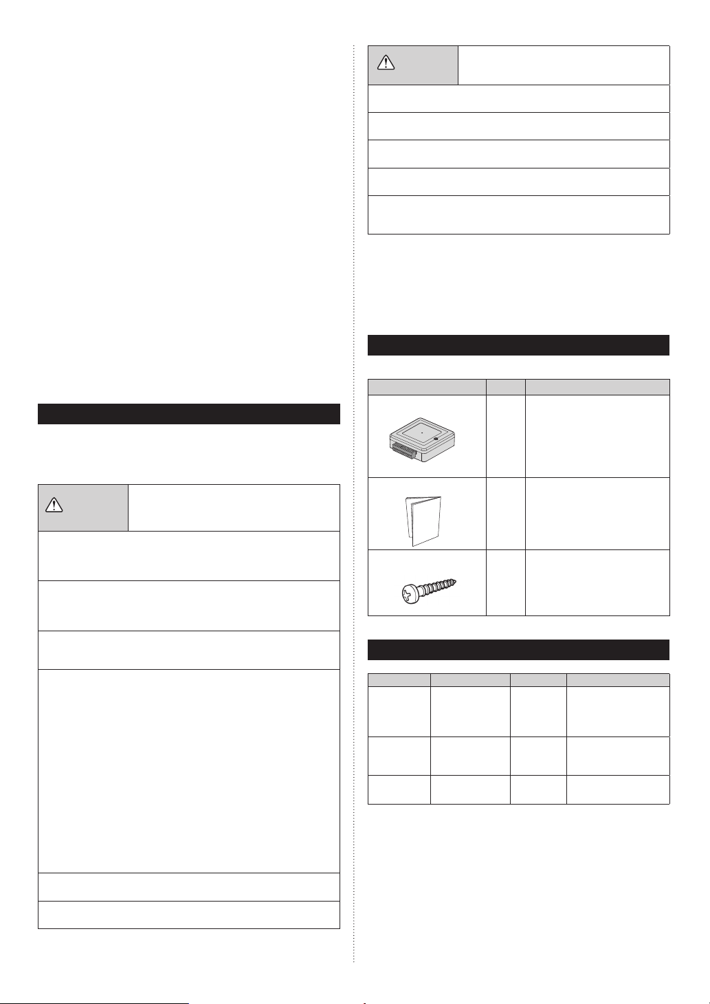
2. MAIN UNIT AND ACCESSORIES
The following installation parts are supplied. Use them as required.
Name and Shape Q’ty Application
Thermostat convertor
Installation manual
Screw (M4 x 16 mm)
This product
1
This manual
1
For mounting this product
2
3. ELECTRICAL REQUIREMENT
Use Size Cable type Remarks
Remote controller cable
(2-wire type)
Remote controller cable
(3-wire type)
Thermostat
wires
*: Use shielded cable in accordance with local rules for remote controller
cable.
16~22AWG
(0.33 to 1.25 mm
22AWG
2
(0.33 mm
18AWG
2
(0.82 mm
2
)
)
)
Sheathed
PVC cable*
Sheathed
PVC cable*
Sheathed
PVC cable*
Non-polar 2 core,
twisted pair
Maximum cable length:
1,640 ft (500m)
Polar 3core
Maximum cable
length: 82 ft (25m)
Maximum cable
length: 164 ft (50m)
En-1
Page 3
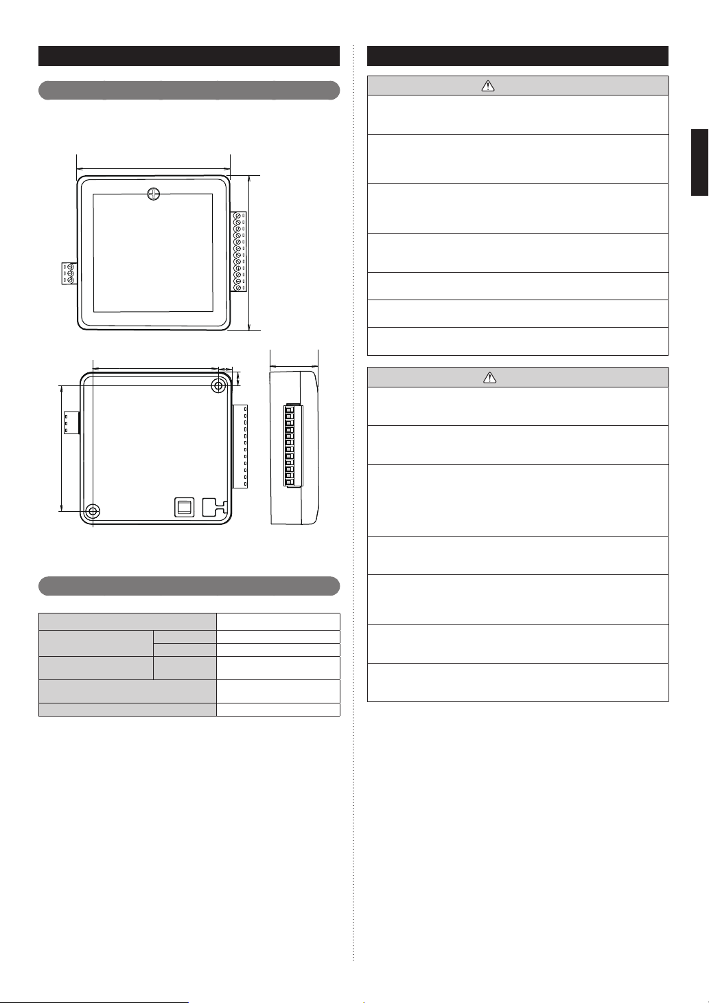
4.
SELECTING AN INSTALLATION LOCATION
Dimensions
4. 1.
This product is comprised of a body and cover.
3-7/16 (86.7)
2-7/8 (72.7)
Set the bottom side to a fl at place.
Specifi cations
4. 2.
Power consumption (W)
Temperature °F (°C)
Humidity (%) Packaged
Dimensions
H x W x D in (mm)
Weight oz. (g)
Upper side
2-7/8 (72.7)
Bottom side
Operating
Packaged
1/4 (7)
1/4
(7)
0.6
32–114 (0–46)
14–140 (-10–60)
0–95 (RH);
No condensation
1-1/16 × 3-7/16 × 3-7/16
(27 × 86.7 × 86.7)
4 (100)
Unit :in (mm)
3-7/16 (86.7)
1-1/16
(27)
5. WIRING
WARNING
Before starting installation work, turn off the power of this product and
the connection destination. Do not turn on the power again until installation is completed. Otherwise, it will cause electric shock or fi re.
Use the accessories or specifi ed connection cable. Do not modify power
supply cable and connection cables other than those specifi ed, do not
use extension cables, and do not use independent branch wiring. It may
cause electric shock or fi re.
Install the connection cables securely to the terminal block. Confi rm that
external force of the cable is not applied to the terminal block. Use the
specifi ed cables. If intermediate connection or insertion fi xing are imper-
fect, it will cause electric shock, fi re, etc.
When connecting the connection cable, route the cables so that the
cover of this product is securely fi xed. If the cover is imperfectly fi xed, it
may cause fi re or overheating of the terminals.
Perform earth (ground) work positively. Do not connect the earth (ground)
cable to a telephone cable, water pipe, or conductor rod.
Perform all wiring works so that the user does not touch the wiring.
Otherwise it will cause injury or electric shock.
If any cable is damaged, do not repair or modify it yourself. Improper
work will cause electric shock or fi re.
CAUTION
Do not bind the remote controller cable and the external input cable
together with or parallel to the power supply cable of the indoor and
outdoor units. It may cause erroneous operation.
When performing wiring work, be careful not to damage the cable or
injure yourself. Also, connect the connectors securely. Loose connectors
will cause trouble, heating, fi re, or electric shock.
Install the indoor unit, outdoor unit, power supply cable, transmission
cable and remote control cable at least 40 in (1 m) away from a television
or radio.
The purpose of this is to prevent TV reception interference or radio noise.
(Even if they are installed more than 40 in (1 m) apart, you could still
receive noise under some signal conditions.)
Perform wiring so that water does not enter this product along the external wiring. Always install a trap to the wiring or take other countermeasures. Otherwise it will cause trouble or electric shock or fi re.
Confi rm the name of each unit and name of each terminal block of the
unit and connect the wiring in accordance with the directions given in the
manual so that there is no incorrect wiring. Incorrect wiring will damage
the electric parts and cause smoke and fi re.
When installing the connection cables near a source of electromagnetic
waves, use shielded cable.
Otherwise, a breakdown or malfunction could result.
The terminal screws and earth (ground) screws have different shapes.
Be sure to install the screws in the correct locations. If the screws are
installed in the wrong locations, the circuit board could be damaged.
En-2
Page 4

5. 1.
Wiring method
Indoor unit
(VRF/single/multi)
Remote controller cable
Max. 16 units
Case 2: Single-stage Cooling and Heating
(Example:Remote controller for 2-wire type)
Thermostat
controller
This product
Thermostat
Controller
The connection example of thermostat convertor and thermostat controller is
shown below.
The connection method is different depending on the type of thermostat controller. Connect them according to the following Cases.
For remote controller cable, 2 kinds of type, which are 2-wire type and 3-wire
type are available depending on the device to be connected.
(1) All wiring shown should be performed with 18 AWG thermostat wire.
(2) Terminals to thermostat controller on this product support 20-30VAC.
(3) High/medium/low fan signals are optional, and may not be available on
all thermostat models.
(4) W2 and Y2 signals are optional, and may be omitted for single-stage
thermostats. In addition, if Y2 and W2 are used, turn ON the DIP switches
SET3-1.
Thermostat
Case 1: Two-stage Cooling and Heating
(Example:Remote controller for 3-wire type)
Thermostat
24 VAC
controller
cable
Indoor unit
Max.
16 units
24 VAC
24 VAC
Transformer*
208/230 VAC
Thermostat convertor
(Locally purchased)
Indoor unit
Max.
16 units
Case 3: Single-stage Cooling and Heating with Dedicated Fan
Speed Relays(Example:Remote controller for 2-wire
type)
Thermostat
controller
Thermostat convertor
24 VAC
Transformer*
208/230 VAC
* Install the transformer, as necessary, per building code and manufacturer’s
installation instructions. Maximum Power: 5.0VA
(Locally purchased)
24 VAC
24 VAC
Transformer*
208/230 VAC
Fan
(Locally purchased)
Thermostat convertor
Indoor unit
Max.
16 units
En-3
Page 5

The names of terminal connected to thermostat have the following meanings.
TC Common (In) from transformer
C Common to thermostat controller
TR Power supply from transformer
R Power supply to thermostat controller
G3 Airfl ow High
G2 Airfl ow Medium
G1 Airfl ow Low
Y2 Cooling Stage 2
Y1 Cooling Stage 1
W2 Heating Stage 2
W1 Heating Stage 1
G Fan
NOTES:
Up to 16 indoor units may be controlled with a single
・
ler, Multiple indoor units connected to convertor operate by the same
operating setting.
Two or more types of VRF1 system, VRF2 system, single model or
・
multi systems cannot be mixed together.
Unit wiring
5. 2.
thermostat
control-
5. 2. 1 Thermostat cable and Remote controller cable
Thermostat cable
1-5/16 in
(33 mm)
1/4 in
(7 mm)
Remote controller cable
9/16 in
For 2-wire type
For 3-wire type
1/4 in
(7 mm)
1/4 in
(7 mm)
(15 mm)
No polarity
9/16 in
(15 mm)
Y2:White
Y3:Black
Y1:Re d
6.
INSTALLING THE THERMOSTAT CONVERTOR
WARNING
Always use the accessories and specifi ed installation work parts. Check
the state of the installation parts. Not using the specifi ed parts will cause
units to fall off, electric shock, fi re, etc.
Install at a place that can withstand the weight of the unit and install
positively so that the unit will not topple or fall.
When installing this product, make sure that there are no children
nearby.
Otherwise, injury or electric shock could result.
CAUTION
Do not set the DIP switch of this product except as specifi ed in this instal-
lation manual or the instruction manual supplied with the air conditioner.
Setting the switches other than specifi ed will cause an accident or
trouble.
Use an insulated screwdriver to set the DIP switches.
Before opening the cover of this product, completely discharge static
electricity charged on your body. Otherwise, failure or malfunction could
result.
Do not touch the circuit board and circuit board parts directly with your
hands.
Otherwise, injury or electric shock could result.
Tightening the mounting screws too tight will damage the body of this
product.
• When using the indoor unit without Fan mode, do not
connect G (Fan), G1, G2, and G3 signals. Otherwise air
conditioner might operate incorrectly.
• If the air conditioner system is a heat pump type, please
select “ Priority on Administrative Indoor Unit” in the setting
of priority mode by PUSH SWITCH of outdoor unit (refer to
installation manual of outdoor unit). Furthermore, please
complete “Administrative Indoor Unit Setting” for indoor unit
which is connected to this Thermostat Convertor by using
the wired remote controller (refer to installation manual of
remote controller.)
NOTES:
When this product is used, do not use the remote controller because
indoor unit is controlled centrally by thermostat controller.
However, the remote controller connecting is temporarily required for the
initial setting. During the initial setting by remote controller do not connect Thermostat Convertor to indoor unit.
After when all initial setting is completed, disconnect the wired remote
controller. Then connect Thermostat Converter to indoor unit at fi rst time.
WARNING
Tighten the terminal screws to the specifi ed torques, otherwise,
abnormal overheating may be occurred and possibly cause heavy
damage inside the unit.
Tightening torque
M2 screw
Remote controller / Y1, Y2, Y3
Thermostat input /
Y1, Y2, G1, G2, G3, R, TR, C, TC
To peel the sheath from the cables, use a dedicated tool that will not
damage the conductor of the cable.
When installing a screw on the terminal block, do not cut the cable
by overtightening the screw. On the other hand, a loosen screw can
cause faulty contact, which will lead to a communication failure.
G, W1, W2,
CAUTION
1.9 to 2.2 lbf·in
(0.22 to 0.25 N·m)
(2.2 to 2.5 kgf·cm)
Connecting the cables
6. 1.
(1) For thermostat cable, use the single wire of 18AWG thermostat wire.
(2) Power-supply voltage of thermostat (TC, TR) is 20 to 30VAC.
(3) Insert the cable to the connected terminal and fi x with screw using
screw driver.
(4) For remote controller cable, 2 kinds of 2 kinds of type, which are
2-wire type and 3-wire type are available depending on the device to
be connected.
(5) The number of connected thermostat cable is different the type of
thermostat controller.
(6) For details of connection method, refer to Case 1 to Case 3 of “5.
Wiring”.
En-4
Page 6

7.
CONNECTION OF REMOTE CONTROLLER CABLE
CAUTION
When connecting the remote controller cable to the indoor unit, do not
connect it to the outdoor unit or the power terminal block. It may cause a
failure.
When connecting Indoor unit and
thermostat convertor with the Remote
controller cable, the following items
should be considered.
Remote controller cable
This product
There are 2 methods to connect the remote controller cable to the indoor
unit. One is the connection using connecting cable contained by indoor
unit, and the other is the connection the remote controller cable is connected to the exclusive terminal block of the indoor unit.
Exclusive terminal block for remote controller connection method is different depending on each model. Modify the remote controller cable as per
below description and connect it.
(For the details, refer to the installation manual of the indoor unit to be
used.)
(1)
When connecting to the connector
Indoor unit
Red
White
Black
Case 1: For non-polar 2-wire
Use a tool to cut off the terminal on the end of the remote controller cable,
and then remove the insulation from the cut end of the cable as shown
in Fig. 1. Connect the remote controller cable and connecting cable as
shown in Fig. 2. Be sure to insulate between the cables.
Fig.1 Fig.2
13/16 in
(20 mm)
Remote controller
cable (Non-polar)
Insulated
connection
White
Red
Connecting cable
(The number of terminal
is different depending
Black
on the model.)
Cut and
insulate
Case 2: For polar 3-wire
Modify the cable as per below methods.
Use a tool to cut off the terminal on the end of the remote controller
cable, and then remove the insulation from the cut end of the cable as
shown in Fig. 1.
Connect the remote controller cable and connecting cable as shown in
Fig. 2.
Be sure to insulate between the cables.
Fig. 1 Fig. 2
13/16 in
(20 mm)
Remote
controller cable
Insert it to the connector.
Connecting cable
Remote controller cable
When the board has the 2WIRE/3WIRE DIP switch on it, set it to
3WIRE.
For how to set, see “Case 1: For non-polar 2-wire”.
(2)
When connecting to the exclusive terminal block
Connect the end of remote controller cable directly to the exclusive
terminal block.
If there is the 2WIRE/3WIRE switch on the PC board of the indoor unit,
set it to match the connection method of the connected remote controller cable.
Example) Connection of non-polar 2-wire
Functional earthing
(If necessary)
Remote controller
cable
* Layout of terminal block and
Terminal block
PC board is varies, depending
on the type of indoor unit.
Red
White
Red
White
Insulated connection
Black
Connector
Set to “2WIRE” the
DIP switch (SW1)
Connector
Black
Indoor unit
PCB
PCB
Terminal block
to outdoor unit /
power supply
Connecting
cable
Indoor unit
PC board
Insert it to the connector. Set to “2WIRE” the DIP switch (SW1) on the
PC board of the indoor unit.
Set to “2WIRE” the
DIP switch (SW1)
Connect to earth
(ground) screw
Remote controller
cable (Non-polar)
* Layout of Connector and PC
board is varies, depending on
the type of indoor unit.
Functional earthing
(If necessary)
Connecting cable
Connector
(adapter)
Indoor unit
PC board
Connector CNC01
(onboard)
SW1
Indoor unit
PC board
En-5
Page 7

8. CIRCUIT BOARD SETTING
Remove the cover of main unit by the following procedure to perform the
initial setting.
Tightening torque
M3 screw
When the cover is removed, the circuit board appears.
The circuit board has DIP switches and LEDs as shown below.
4.4 to 5.3 lbf·in
(0.5 to 0.6 N·m)
(5 to 6 kgf·cm)
Heating setting temperature
SW
SET3-3
OFF
OFF ON 81 (27) Pattern2
ON OFF 75 (24) Pattern3
ON ON 70 (21) Pattern4
SW
SET3-4
OFF
Heating Stage 1 setting
temperature
°F (°C)
86 (30) Pattern1
(: Factory setting)
(3)-2 Two-stage setting
Cooling setting temperature
Cooling Stage 1 setting
SW
SET3-2
OFF
ON 72 (22) 68 (20) Pattern2
temperature
°F (°C)
68 (20) 64 (18) Pattern1
Cooling Stage 2 setting
temperature
°F (°C)
(: Factory setting)
Heating setting temperature
Heating Stage 1
SW
SET3-3
OFF
OFF ON 77 (25) 82 (28) Pattern2
ON OFF 75 (23) 79 (26) Pattern3
ON ON 70 (21) 75 (24) Pattern4
SW
SET3-4
OFF
setting
temperature
°F (°C)
81 (27) 86 (30) Pattern1
NOTES:
These are the limit temperature for cooling and heating.
Energy saving performance is improved in the order from Cooling Pattern 1 to 2 and Heating Pattern 1 to 4.
Heating Stage 2
setting
temperature
°F (°C)
(: Factory setting)
Remarks
Remarks
Remarks
(4) Delay off setting
Perform the initial setting using 3 DIP switches (SET 1 to 3)
on the circuit board.
Delay OFF:
Delay OFF is the function to operate continuously after reaching to the
setting temperature of thermostat.
This function may make the air conditioning effi cient.
(1) 2WIRE/3WIRE setting (SET1)
Remote controller 2WIRE/3WIRE switching SW
“Factory setting : 2WIRE”
Set the Delay OFF time by SW SET 2-3 and SW SET 2-4.
(5) Fan setting (G signal)
Set matched with the connection method of the remote controller cable to be connected.
(2) Single-stage or Two-stage setting
SW
SET3-1
OFF
ON Temperature setting: Two-stage
Temperature setting: Single-stage
Contents
(: Factory setting)
(3) Temperature setting
(3)-1 Single-stage setting
Cooling setting temperature
SW
SET3-2
OFF
ON 68 (20) Pattern2
Cooling Stage 1 setting
temperature
°F (°C)
64 (18) Pattern1
Remarks
(: Factory setting)
SW
SET2-3
OFF
OFF ON 5 minutes
ON OFF 10 minutes
ON ON 20 minutes
SW
SET2-1
OFF
OFF ON High
ON OFF Med.
ON ON Low
SW
SET2-4
OFF
SW
SET2-2
OFF
Delay off time
0 minutes
Indoor unit airfl ow
Auto
(: Factory setting)
(: Factory setting)
En-6
Page 8

9. TURNING ON THE POWER
(1) Check this product wiring and switch settings on the circuit board.
(2) Check the wiring and switch settings for the VRF system or multi
system or single model. For the wiring and switch settings method,
refer to the installation instruction sheet of each unit.
(3) Turn on the power for the VRF system etc.
(4) Power will be supplied from the indoor unit to this product.
▪ This product will be initialized and the power turned on.
LED1 (green) and LED2 (orange) will fl ashing.
▪ After initial setting is completed, operation will be restarted auto-
matically.
LED1 (green) lights.
▪ This product does not operate during initialization.
* An error code will appear on LED in the event of a malfunction.
10. LED DISPLAY
Normal code
10. 1.
Normal indications
LE
D1
LE
D2
(green)
(orange)
Display mode : On
: Off
: 1s ON / 1s OFF
LED3
(red)
LE
(blue)
Normal contents
D4
During initialization (during
initialization sequence)
Normally operating
11. USAGE
• For the usage and installation of thermostat controller,
refer to the operating manual and installation manual of
thermostat controller.
Error code
10. 2.
Error indications
LE
D1
LE
D2
(orange)
(n) (n) Thermostat convertor error
(n) (n) Indoor unit error
(red)
(green)
LED3
LE
D4
(blue)
Error contents
Display mode : On
: Off
: 0.5s ON / 0.5s OFF
: 0.1s ON / 0.1s OFF
( ) : Number of flashing
En-7
Page 9

 Loading...