

Page 1

Multi Air Conditioning System
for Buildings
VRF (FREELY SELECTABLE MULTI TYPE SYSTEM)
SERVICE MANUAL
CONFIDENTIAL
Page 2

Multi Air Conditioning System
for Buildings
VRF (FREELY SELECTABLE MULTI TYPE SYSTEM)
SERVICE MANUAL
– 2 –
Page 3

CONTENTS
1. OUTLINE OF SYSTEM
1-1
MODEL CONSTRUCTION
1-2
SYSTEM CONSTRUCTION CONDITIONS
1-2-1
1-2-2
1-3
(1)
(2)
REFRIGERANT PIPING
SYSTEM WIRING
ADDRESS SETTING
KINDS OF ADDRESS AND SETTING RANGE
EXAMPLES OF SYSTEM SETTING
................................................................................................
................................................................................................
2. TEST RUN ADJUSTMENT
CHECK ITEMS BEFORE TEST RUN
2-1
2-2
2-2-2
OUTDOOR PC BOARD2-2-1
TEST OPERATION USING REMOTE CONTROLLER
TEST RUN CONTROL2-3
................................................................................................TEST RUN METHOD
3. REFRIGERANT PIPE SYSTEM DIAGRAM
COOLING ONLY / HEAT PUMP TYPE3-1
3-2
4. FUNCTION OF PRINTED CIRCUIT BOARD
PCB LAYOUTS4-1
MICROPROCESSOR BLOCK DIAGRAM4-2
MICROPROCESSOR FUNCTION LIST4-3
FUNCTION AND SETTING OF EACH SWITCH4-4
INDOOR UNIT
OUTDOOR UNIT
REMOTE CONTROLLER
..........................................................................................................
..........................................................................................................
.......................................................................................................
5. OUTDOOR UNIT OPERATION CONTROL
5-1
COMPRESSOR OPERATION CONTROL
5-1-1
5-1-2
5-1-3
5-2
5-3
5-4
5-5
5-6
5-7
5-8
5-9
5-10
5-11
5-12
5-13
OPERATION STOP CONDITION
COMPRESSOR OUTPUT PATTERN
3 MINUTES RESTART PREVENTION ( 3 MIN ST )
HEAT EXCHANGER CAPACITY CONTROL
OUTDOOR FAN MOTOR CONTROL
EXPANSION VALVE 1/2 CONTROL
FOUR-WAY VALVE 1 CONTROL
CIRCULATING SAVE AMOUNT CONTROL
SOLENOID VALVE 2 CONTROL
FOUR-WAY VALVE 5 CONTROL
DEFROSTING CONTROL
OIL RETURN CONTROL
OIL RECOVERY CONTROL
PROTECTION FUNCTION
PUMP DOWN CONTROL
......................................................................................
......................................................................................
......................................................................
....................................................................
......................................................................................
...........................................................................................
....................................................................
.........................................................................................HEAT RECOVERY TYPE
.................................................................
....................................................................
........................................................................................ 36
......................................................................
.................................................................
......................................................................
.........................................................................
...........................................................................
..............................................................................
...........................................................................
........................................................................................
......................................................................................
.................................................................................
...................................................................................
......................................................................................
– 3 –
.............................................................
.......................................................
.......................................
.......................................................
...............................................................
..........................................
.......................................................5-1-4 COMPRESSOR RECOVERY OPERATION
............................................................
............................................................
12
13
13
15
19
20
20
20
22
23
24
25
26
28
30
30
34
43
43
43
43
44
45
46
48
49
5
51
52
53
54
55
56
57
5
7
7
0
Page 4

6. INDOOR UNIT OPERATION
6-1 TIMER CONTROL
6-2 FAN CONTROL
6-2-1
6-3
6-3-3
6-3-4
6-3-5
6-5
6-6
6-7
"AUTO" POSITION .............................................................................................
"LOW" "MED" AND "HIGH" POSITION6-2-2
MASTER CONTROL
OPERATION MODE CONTROL ...........................................................................
"COOL" POSITION
"HEAT" POSITION
"FAN" POSITION
LOUVER CONTROL6-4
ELECTRONIC EXPANSION VALVE CONTROL
AUTO RESTART
DRAIN PUMP OPERATION
..................................................................................................... 59
..........................................................................................................
..................................................................................................
..............................................................................................."AUTO" POSITION6-3-2
...............................................................................................
...............................................................................................
.................................................................................................
.................................................................................................
......................................................................................................
....................................................................................
7. WIRING DIAGRAM
INDOOR UNIT
OUTDOOR UNIT
............................................................................................................
.........................................................................................................
8. TROUBLESHOOTING
8-1
INDOOR UNIT
8-1-1
8-1-2
8-2-1 NORMAL OPERATING DISPLAY
8-4
8-5-1 CHARACTERISTICS OF THERMISTOR
8-5-3 ELECTRIC EXPANSION VALVE
NORMAL OPERATION DISPLAY
ABNORMAL OPERATION DISPLAY
OUTDOOR UNIT8-2
ABNORMAL OPERATION DISPLAY8-2-2
REMOTE CONTROL UNIT8-3
ERROR CODE & TROUBLESHOOTING
INDOOR UNIT TROUBLESHOOTING 91...................................................................
OUTDOOR UNIT TROUBLESHOOTING 96................................................................
CENTRAL REMOTE CONTROLLER TROUBLESHOOTING .................................
OTHERS8-5
PRESSURE SENSOR8-5-2
RB UNIT (HEAT RECOVERY TYPE ONLY)8-5-4
OTHERS8-5-5
............................................................................................................
.......................................................................................................
.......................................................................................
...................................................................................................................
.........................................................................................
..............................................................................................................
.................................................................
........................................................................
....................................................................
........................................................................
...................................................................
................................................................
.......................................................TROUBLESHOOTING (NO ERROR CODE)8-4-1
..............................................................
........................................................................
........................................................
1
64
64
64
65
656-3-1
65
69
69
70
71
74......................................................
74
74
75
83
84
84
85
88
88
89
90
91
091
141
24
241
261
261
261
261
9. IN USE OF THE NEW REFRIGERANT R407C
10. DISASSEMBLY ILLUSTRATION
11. PARTS LIST
................................................................................................................
..........................................................................
– 4 –
...................................................
291
341
731
Page 5

1. OUTLINE OF SYSTEM
1-1 MODEL CONSTRUCTION
■ OUTDOOR UNITS
TYPE
COOLING ONLY
HEAT PUMP
HEAT RECOVERY
POWER SOURCE
3 PHASE 4 LINE
380 415V 50Hz
380 415V 50Hz
380 415V 50Hz
CAPACITY RANGE
28.0 kW
28.0 kW
28.0 kW
Compact size
1,380
1,300
Serial installation possible
650
■ INDOOR UNITS
10 types, 39 models ranging from 2.15kW to
17.0kW.
Type
Capacity
kw Model code
14.1
(17.0)
12.7
10.5
8.8
6.8
(7.05)
5.3
(5.7)
4.05
3.6
2.8
2.15
54
(60)
45
36
30
24
(25)
18
(20)
14
12
Ceiling/
Floor
9
7
Ceiling
(High Static
Pressure)
Cassette
(compact)
: 2002
CassetteDuctDuctDuct Duct
Wall
mounted
Wall
mounted
– 5 –
Page 6
UTR-BP54A Less than 60
UTR-BP90A More than 61 or more
UTR-BP54R Less than 60
UTR-BP90R More than 61 or more
Model Max. connectable indoor units
UTF-Y90A4A 4
UTF-Y54A1A 1
Type Model Total model code of connectable indoor unit
Heat pump
Heat recovery
UTR-HD906A 3 6
UTR-HD908A 7 8
UTR-HD906R 3 6
UTR-HD908R 7 8
Type Model
Connectable indoor units
Cooling only
Heat pump
Heat recovery
RB (REFRIGERANT BRANCH) UNIT
SEPARATION TUBE
Above units are required during heat recovery operation.
HEADER
Cooling only
– 6 –
Page 7
■
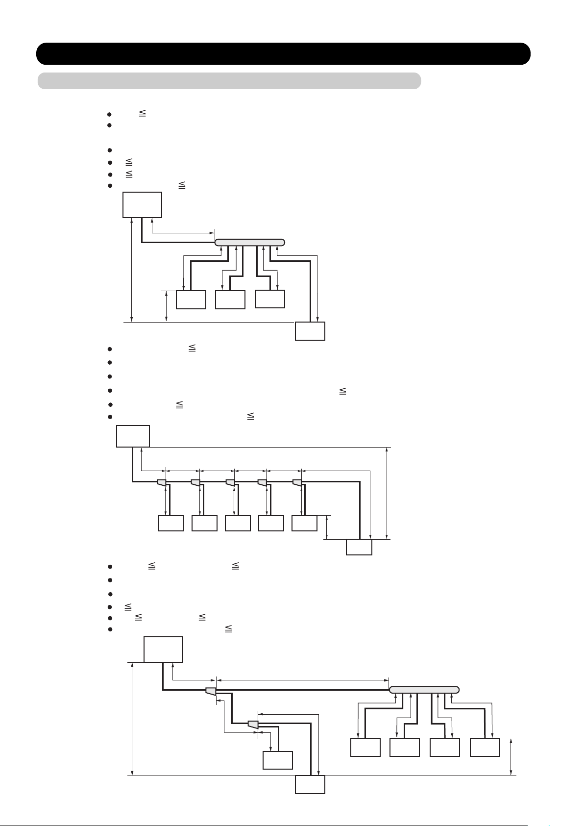
1-2 SYSTEM CONSTRUCTION CONDITIONS
1-2-1 REFRIGERANT PIPING
COOLING ONLY / HEAT PUMP MODEL
a+e 100m (actual pipe length)
Difference in height between outdoor unit and indoor units (H1) maximum 50m.
(For the outdoor unit stated below:maximum 40m)
Difference in height between adjacent indoor units (H2) maximum 15m.
e 40m (actual pipe length)
a 70m (actual pipe length)
a+b+c+d+e 200m (total pipe length)
Outdoor
unit
a
H1
H2
Indoor
unit
Indoor
unit
Indoor
unit
dcb
Indoor
unit
e
a+b+c+d+e+f 100m (actual pipe length)
Difference in height between outdoor unit and indoor units (H1) maximum 50m.
Difference in height between adjacent indoor units (H2) maximum 15m.
From outdoor unit to first separation tube a 70m (actual pipe length)
b+c+d+e+f 40m (actual pipe length)
a+b+c+d+e+f+g+h+i+j+k 200m (total pipe length)
Outdoor
unit
a
bcde
g h i j k
Indoor
unit
Indoor
unit
Indoor
unit
Indoor
unit
Indoor
unit
H2
Indoor
unit
H1
f
a+g+i 100m a+b+f 100m (actual pipe length)
Difference in height between outdoor unit and indoor units (H1) maximum 50m.
Difference in height between adjacent indoor units (H2) maximum 15m.
a 70m (actual pipe length)
g+i 40m b+f 40m (actual pipe length)
a+b+c+d+e+f+g+h+i 200m (total pipe length)
Outdoor
unit
h
Indoor
unit
b
– 7 –
Indoor
unit
Indoor
unit
f
H2
edc
i
Indoor
unit
Indoor
unit
Indoor
unit
H1
a
g
Page 8
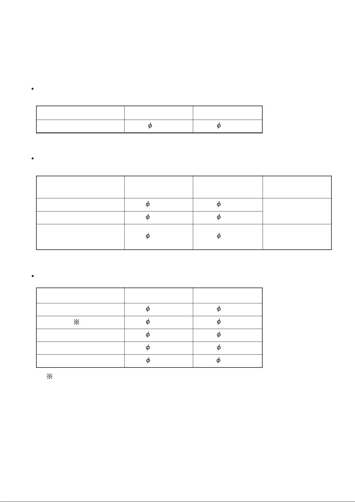
PIPE SIZE
COOLING ONLY / HEAT PUMP MODEL
Pipe size connected to outdoor unit.
Model Gas Pipe Liquid Pipe
AO 90 28.58 12.7
Between two adjacent refrigerant branch kits.
(unit : mm)
(unit : mm)
Total model code of
Gas Pipe Liquid Pipe Separation Kit
indoor unit
Less than 30 15.88 9.53
UTR-BP54A
31 or more to 60 19.05 9.53
61 or more 28.58 12.7 UTR-BP90A
Connection pipe size of indoor unit.
(unit : mm)
Model code of indoor unit Gas Pipe Liquid Pipe
7, 9 9.53 6.35
12, 14
( )
18
12.7 6.35
18, 20, 24, 25 15.88 6.35
30
15.88
9.53
36, 45, 54, 60 19.05 9.53
Cassette(compact) only
– 8 –
Page 9
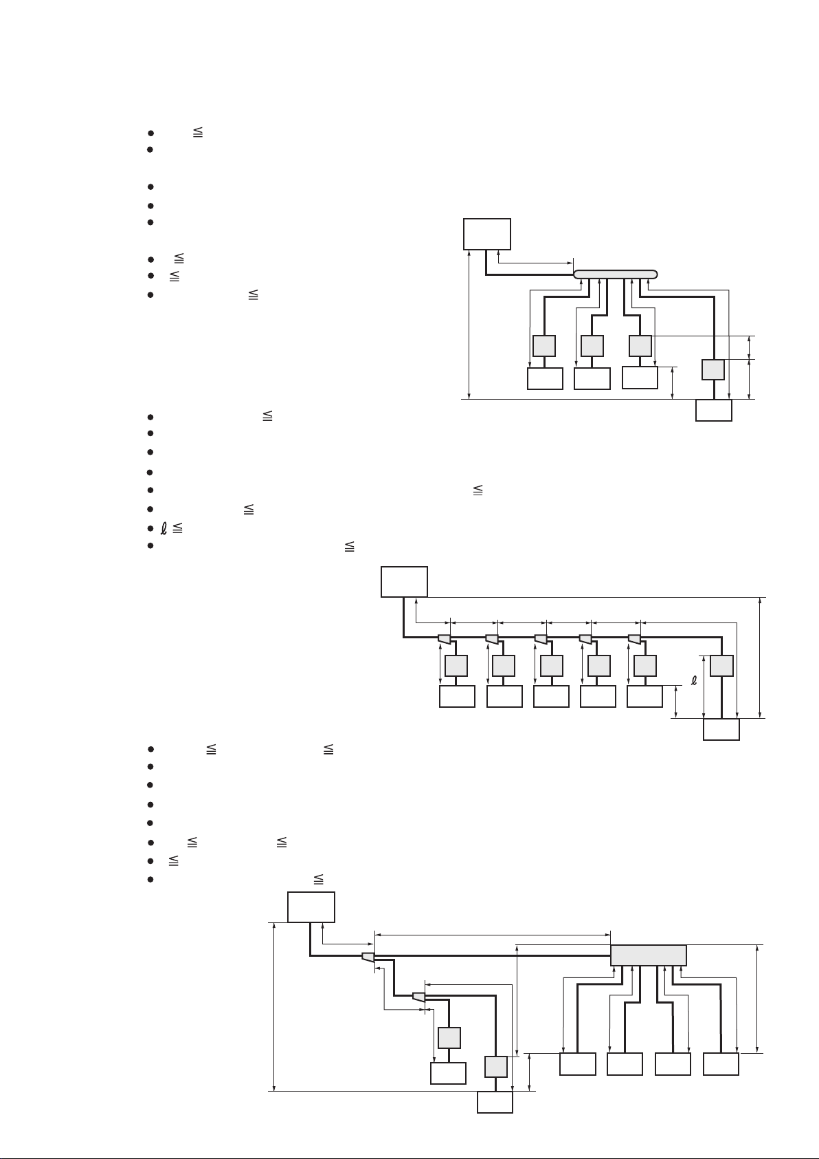
■
HEAT RECOVERY MODEL
a+e 100m (actual pipe length)
Difference in height between outdoor unit and indoor units (H1) maximum 50m.
(For the outdoor unit stated below : maximum 40m)
Difference in height between adjacent indoor units (H2) maximum 15m.
Difference in height between RB unit and RB unit (H3) 15m or less.
Difference in height between
RB unit and indoor unit (H4) 5m or less
e
40m (actual pipe length)
f
10m (actual pipe length)
a+b+c+d+e 200m (total pipe length)
.
Outdoor
unit
a
H1
a+b+c+d+e+f 100m (actual pipe length)
b
RB
unit
Indoor
unit
c
Indoor
RB
unit
unit
RB
unit
Indoor
unit
d
RB
unit
H2
Indoor
unit
Difference in height between outdoor unit and indoor units (H1) maximum 50m.
Difference in height between adjacent indoor units (H2) maximum 15m.
Difference in height between RB unit and indoor unit (H3) 5m or less.
From outdoor unit to first separation tube a 70m (actual pipe length)
b+c+d+e+f 40m (actual pipe length)
10m (actual pipe length)
a+b+c+d+e+f+g+h+i+j+k 200m (total pipe length)
Outdoor
unit
a
bcde
g h i j k
RB
unit
Indoor
unit
RB
unit
Indoor
unit
RB
unit
Indoor
unit
RB
unit
Indoor
unit
RB
unit
Indoor
unit
H3
H2
Indoor
a+g+i 100m a+b+f 100m (actual pipe length)
Difference in height between outdoor unit and indoor units (H1) maximum 50m.
Difference in height between adjacent indoor units (H2) maximum 15m.
Difference in height between RB unit and RB unit (H3) 15m or less.
Difference in height between RB unit and indoor unit (H4) 5m or less.
g+i 40m b+f 40m (actual pipe length)
j 10m (actual pipe length)
a+b+c+d+e+f+g+h+i 200m (total pipe length)
Outdoor
unit
a
b
RB unit
4 brunch
RB
unit
unit
e
H3
H4, f
H1
f
H1
g
edc
RB
unit
Indoor
unit
H3
i
H2
Indoor
unit
Indoor
unit
Indoor
unit
Indoor
unit
– 9 –
h
RB
unit
Indoor
unit
H4
f
j
Page 10
HEAT RECOVERY MODEL
Pipe size connected to outdoor unit.
(unit : mm)
Model Suction Gas Pipe
Discharge Gas Pipe
Liquid Pipe
AO 90 28.58 19.05 12.7
Between two adjacent refrigerant branch kits.
Total model code of Suction Discharge
Liquid Pipe
Separation Kit
indoor unit Gas Pipe Gas Pipe
Less than 30 15.88 12.7 9.53
UTR-BP54R
31 or more to 60 19.05 15.88 9.53
61 or more 28.58 19.05 12.7 UTR-BP90R
Connection pipe size of indoor unit.
(unit : mm)
(unit : mm)
Model code of indoor unit
Gas Pipe Liquid Pipe
7, 9 9.53 6.35
12, 14 12.7 6.35
18, 20, 24, 25 15.88 6.35
30
15.88
9.53
36, 45, 54, 60 19.05 9.53
– 10 –
Page 11
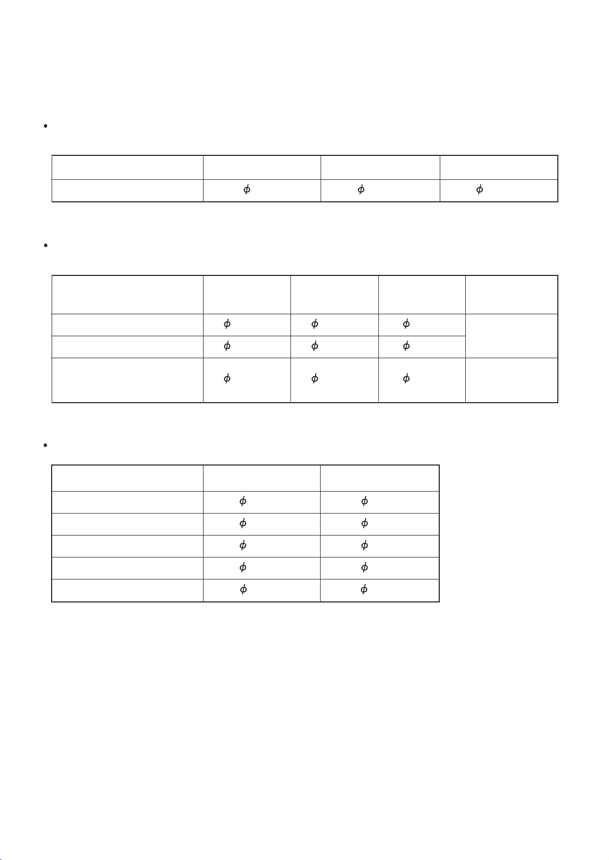
ADDITIONAL CHARGE
Up to a pipe length of 7.5 m, charging with additional refrigerant is not necessary.
If the pipe length exceeds 7.5 m, charging with refrigerant is necessary.
Charge with additional refrigerant in the amounts shown in the table below.
(1) Pipe length
Liquid pipe (mm) 12.7 9.53 6.35
Additional refrigerant
0.1 0.05 0.03
(R407C) (kg/m)
(2) System type
It is necessary to add refrigerant to all connected Indoor unit.
Add refrigerant to the corresponding type as shown in the Table for every connected Indoor unit to the
refrigerant system.
Example : When AR30 x2 and AU18 x2 are connected to the refrigerant system.
" Additional charge of system type" is 1.0(kg)x2 +0.65(kg)x2=3.3(kg)
Model / Model code
AS
AU
AB
AR
0.65
0.4
7 9
0.65120.65
0.4
0.65
0.45
14
0.9
0.65
0.65
0.45
18
0.65
0.65
0.7
ADDITIONAL CHARGE = (1) + (2)
20
0.9
0.8
24/25
0.9
0.9
0.8
0.8
1.0
1.0
1.0
1.0
30
36
45
54
1.5
1.5
1.0
2.0
amount of refrigerant (kg)
1.0
2.0
1.5
1.0
60
2.0
– 11 –
Page 12

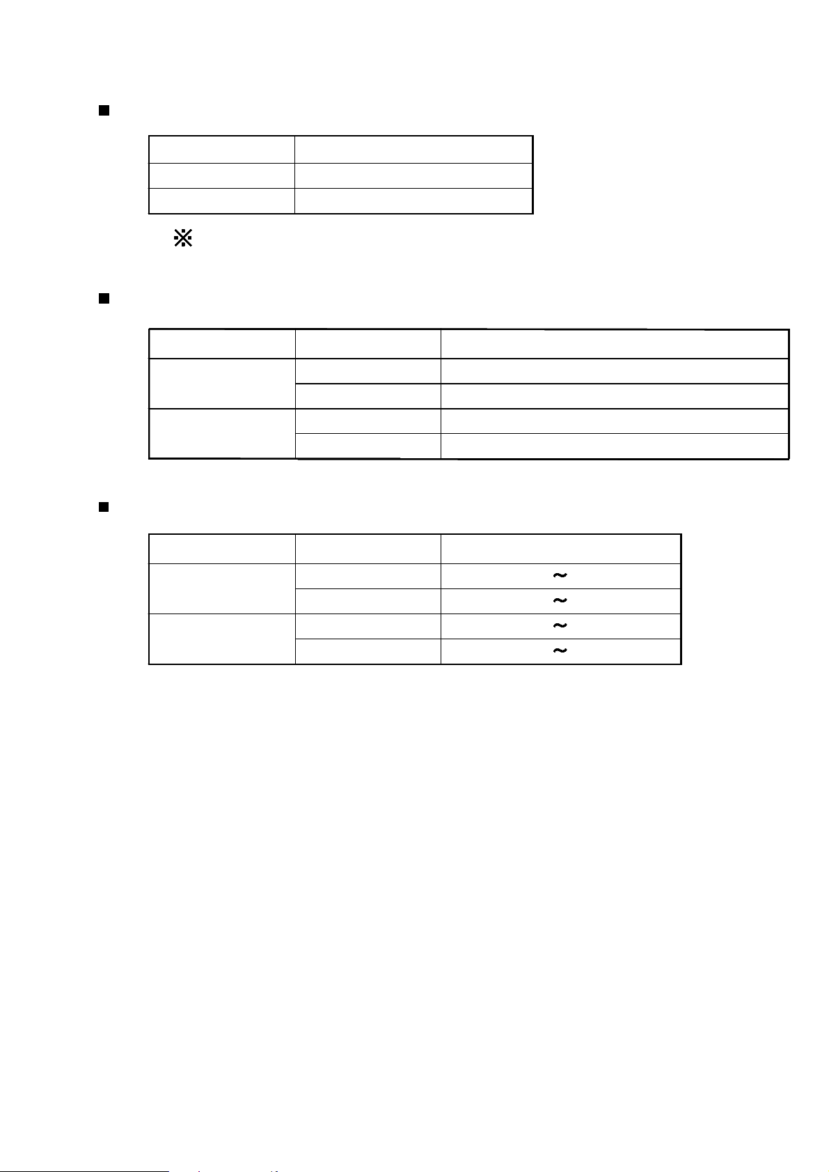
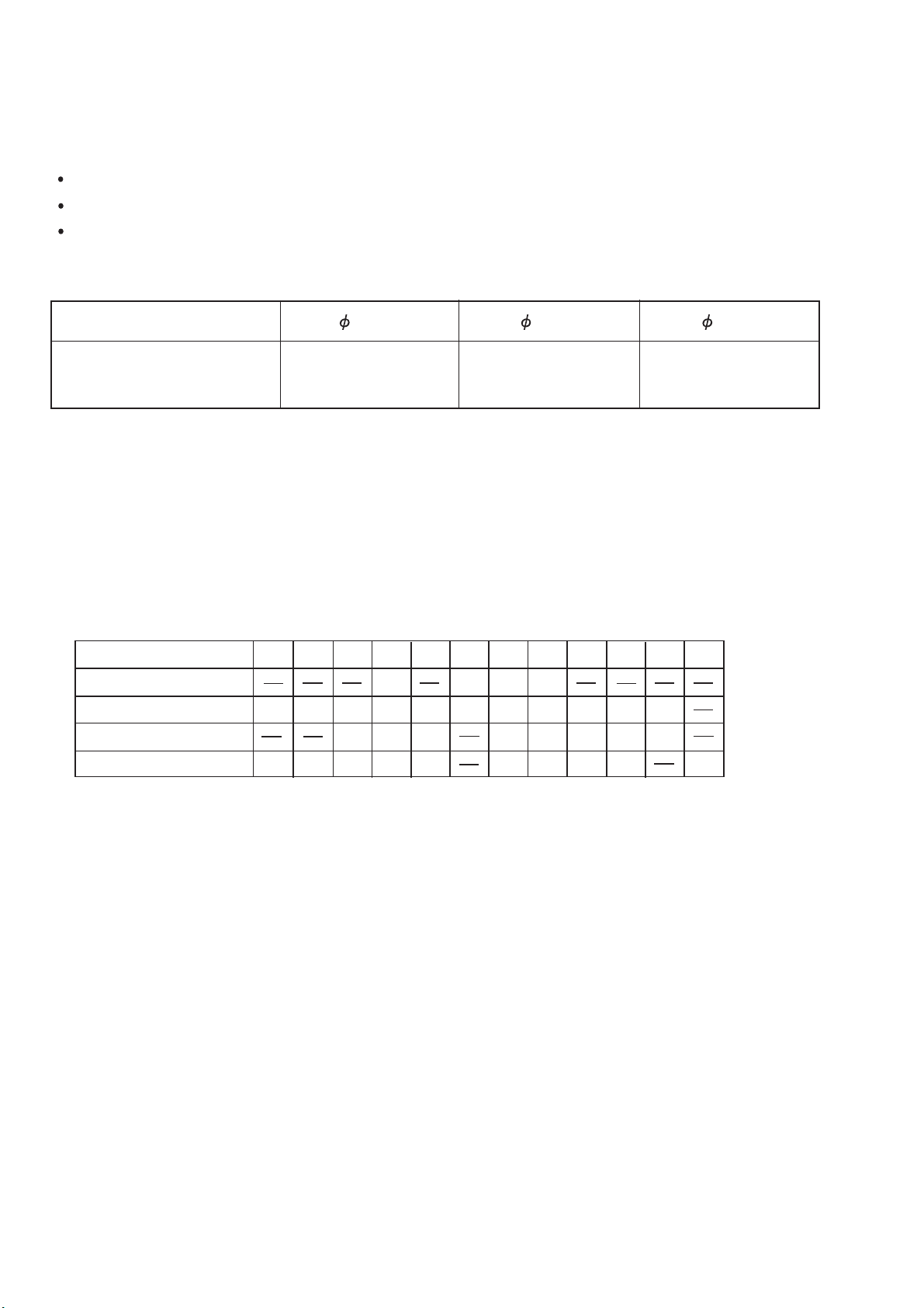
1-2-2 SYSTEM WIRING
Use
Outdoor
2
unit
Indoor
Power supply
cable (mm )
unit
Transmission
cable (mm )
2
Wired remote control
cable (mm )
1,2
3
4 10m cable attached.
2
The grounding wire is not included in this cable.
Always ground the unit.
Do not bundle the transmission cable with other wires.
Transmission cable between each unit : 200m max
Each unit means indoor unit,outdoor unit,central remote controller,
and signal amplifier.
Total wiring length:maximum 2000m.
However,when wiring exceeds 500m in length,
a signal amplifier (option) is required.
Use the shielded wire specified and always ground(however,one side only).
If not,transmit-receive with a transmission line is not
only impossible normally,but malfunction may occur.
Use the shielded cable in accordance with standards
in the country.
Wiring length of a remote controller group shall be
within 500m.
Size
Maximum H07RN-F or
Minimum equivalent
Maximum H07RN-F or
Minimum equivalent
Maximum
8.0
6.0
2.5
1.5
1.25
Wire type Remarks
Shield cord
(LONWORKS
Minimum
Maximum Sheathed vinyl
Minimum cord cable
0.75
1.25
0.75
compatible part)
3 4 wire 50Hz
380-415V
1 2 wire 50Hz
220-240V
Non-polar
2-core
Polar 3-core
1
2
3
4
Fuse
capacity
per one outdoor unit
5
per one refrigerant system.
6
Model Field fuse
Outdoor
unit
Indoor
unit
40A
20A
5
6
– 12 –
Leakage breaker
40A 100mA 0.1sec or less
20A 40mA 0.1sec or less
Page 13
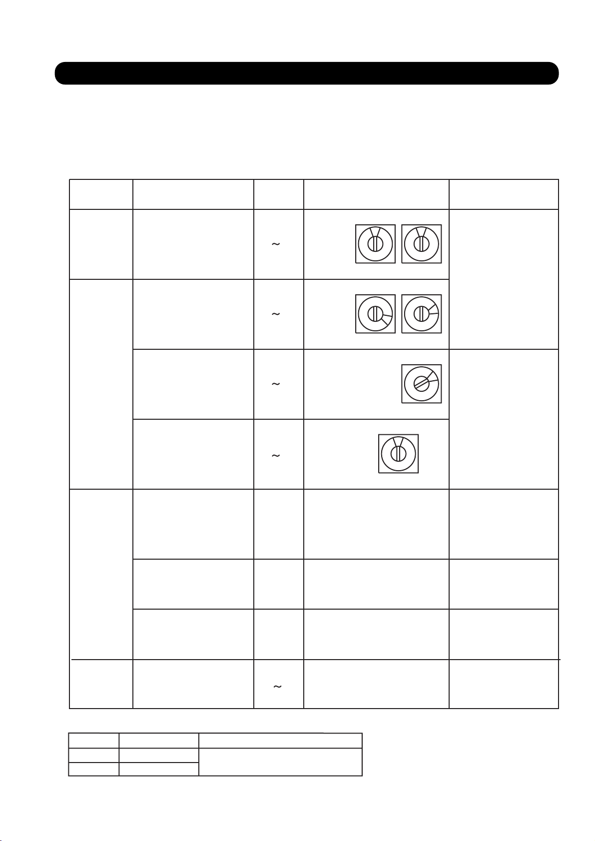
1-3 ADDRESS SETTING
This system is needed to set the address for the indoor unit, outdoor
unit and remote controller and central remote controller.
(1) KINDS OF ADDRESS AND SETTING RANGE
UNIT SETTING
Outdoor
unit
Refrigerant
circuit address
Refrigerant
circuit address
Indoor
unit
Indoor unit address
Remote controller
address
SETTING
RANGE
0 99
0 99
0 15
0 15
TYPE OF SWITCH REMARKS
Setting
example
0
Setting
example
63
Setting
example
2
Setting
example
0
0
SW 9 SW 8
6
SW 8 SW 7
0
Show next page
3
2
SW 5
0
Remote controller
switch 1
Remote
controller
Number of indoor
unit connection
Remote controller
switch 2
Central
remote
Central remote
controller address
controller
INDOOR UNIT CONTROL METHOD
DSW1-4
OFF
ON
METHOD
Master
Slave
Allocate remote
by order from the
ON/OFF
ON/OFF
ON/OFF
combination
0 15
REMARKS
control addresses
master unit
SW 9
DIP SW1-1
DIP SW1-2
DIP SW1-4
Initial setting
Terminator
Number of indoor unit
OFFON: 1 unit
: multiple unit
Shown below
– 13 –
Page 14
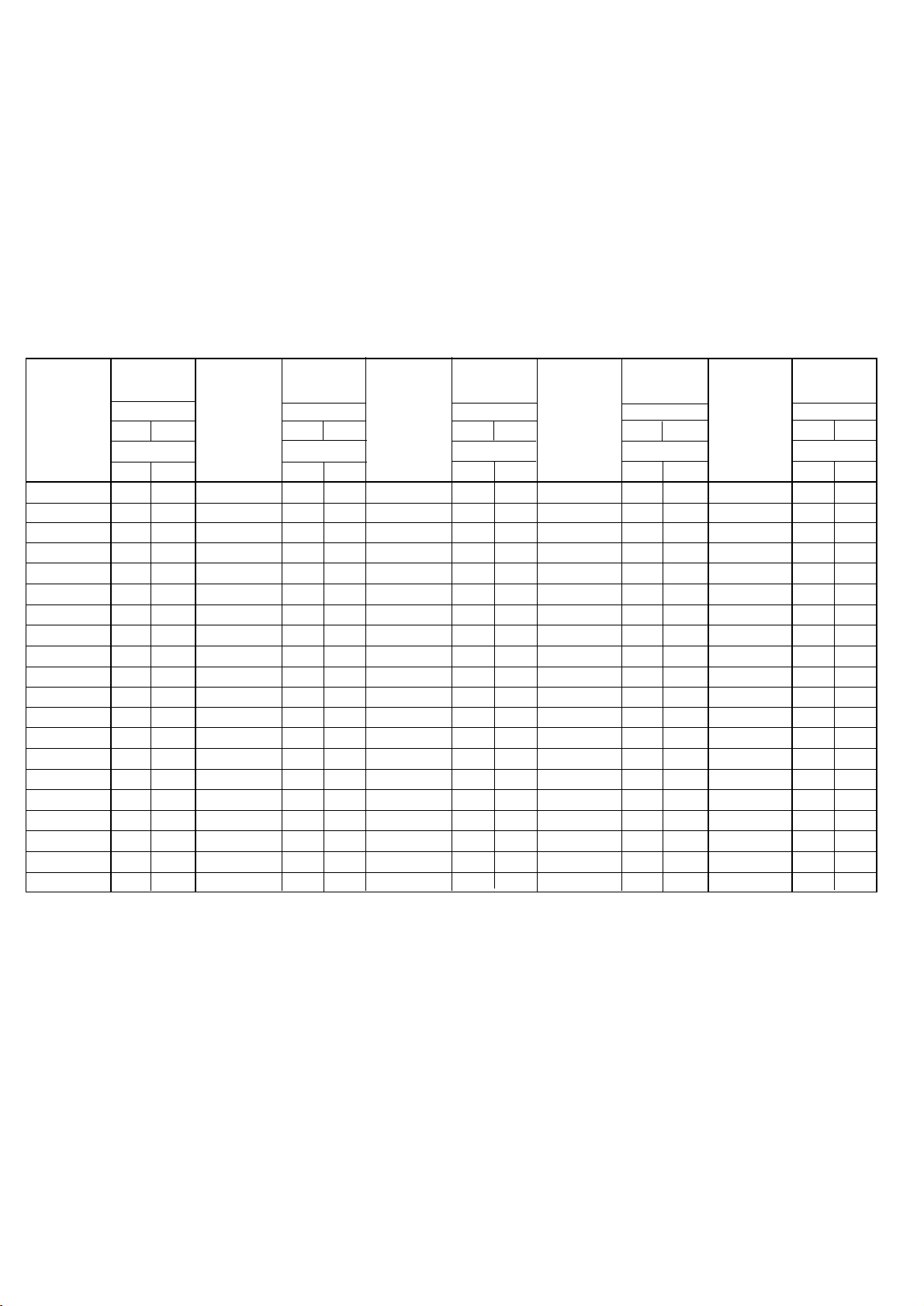
Refrigerant circuit address conversion table
Outdoor unit
Rotary switch (SW 8)- - - Factory setting "0"
Rotary switch (SW 9)- - - Factory setting "0"
Indoor Unit
Rotary switch (SW 7)- - - Factory setting "0"
Rotary switch (SW 8)- - - Factory setting "0"
In case of multiple refrigerant system,set SW 8 and SW 9 Indoor unit SW7 and SW8 as shown
in the table for each refrigerant system.
Do not use a nonexistent switch setting combination.
Example : When SW 9 is set to "1" and SW 8 is set to "14" the refrigerant circuit address will be "30".
Refrigerant
circuit
address
0
1
2
3
4
5
6
7
8
9
10
11
12
13
14
15
16
17
18
19
Rotary
Switch setting
OUTDOOR UNIT
SW9
Refrigerant
circuit
address
SW8
INDOOR UNIT
SW7
SW8
0
0
1
0
2
0
3
0
0
4
5
0
0
6
0
7
0
8
0
9
0
10
0
11
0
12
0
13
0
14
0
15
0
1
1
1
2
1
3
1
20
21
22
23
24
25
26
27
28
29
30
31
32
33
34
35
36
37
38
39
Rotary
Switch setting
OUTDOOR UNIT
SW9
Refrigerant
circuit
address
SW8
INDOOR UNIT
SW8
SW7
4
1
5
1
6
1
1
7
8
1
9
1
1
10
1
11
1
12
1
13
1
14
1
15
0
2
1
2
2
2
2
3
2
4
2
5
2
6
2
7
40
41
42
43
44
45
46
47
48
49
50
51
52
53
54
55
56
57
58
59
Rotary
Switch setting
OUTDOOR UNIT
SW9
Refrigerant
circuit
address
SW8
INDOOR UNIT
SW8
SW7
2
8
2
9
2
10
2
11
2
12
2
13
2
14
2
15
3
0
1
3
2
3
3
3
3
4
5
3
6
3
3
7
3
8
3
9
10
3
3
11
60
61
62
63
64
65
66
67
68
69
70
71
72
73
74
75
76
77
78
79
Rotary
Switch setting
OUTDOOR UNIT
SW9
Refrigerant
circuit
address
SW8
INDOOR UNIT
SW7
SW8
3
12
3
13
3
14
3
15
0
4
1
4
2
4
3
4
4
4
5
4
6
4
7
4
8
4
9
4
10
4
11
4
12
4
13
4
14
4
15
4
90
91
92
93
94
95
96
97
98
99
80
81
82
83
84
85
86
87
88
89
Rotary
Switch setting
OUTDOOR UNIT
SW9
SW8
INDOOR UNIT
SW7
SW8
0
5
1
5
2
5
3
5
4
5
5
5
6
5
7
5
8
5
9
5
10
5
11
5
12
5
13
5
14
5
5
15
6
0
6
1
2
6
6
3
– 14 –
Page 15
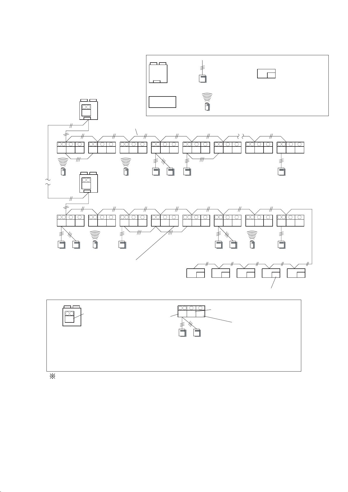
(2) SETTING EXAMPLE
Outdoor unit
9 8
Outdoor
unit
Indoor
unit
0
Wired remote
controller
Wireless remote
controller
Transmission line
(Non-polar 2 core)
8 7
5
0
9 8 7
5
1
9 8 7
5
2
9 8 7
9 8 7 5 9 8 7 5 9 8 7
5
3
4
0 0 0 0 0 00 1 0 0 0 1
5
2 (Max.16 Numbers)
9 8
63
8 7
63 0 163 0263 0363 1463 2563 0 63636 0
5
0
9 8 7
5
9 8 7
5
OFF ONDIP SW1-1
OFF ONDIP SW1-4
9 8 7
5
9 8 7
5
9 8 7
5
9 8 7
00
5
9 8 7
14
5
0 0
0 15 0
9 8 7
Central remote
controller
5
9
5
9
7
0
3
OFF ONDIP SW1-1
OFF ONDIP SW1-4
9 8
63
Refrigeration
circuit address
Rotary-sw9,8
Instructions for setting up the address
1 The refrigerant system address of the indoor and outdoor units can be set to optional numbers
in the range of 0 and 99.
2 Address of the indoor unit can be set to optional numbers in the range of 0 to 15.
3 Set address of the remote controller in the order of 0,1,2,...15.(Blank is impossible)
4 Address of the central remote controller can be set to optional numbers in the range of 0 to 15.
ONDIP SW1-1
Number of the unit
in the group
Refrigeration
circuit address
Rotary-sw8,7
DIP SW1-1 Remote controller address1
DIP SW1-2 Number of indoor unit connection
DIP SW1-4 Remote controller address2
00 01 02 03 04
Central Remote controller (Max.16)
Central remote controller address
5
8 7
63 0
9
6
Indoor unit address
Rotary-sw5
Remote controller address
Rotary-sw9
– 15 –
Page 16
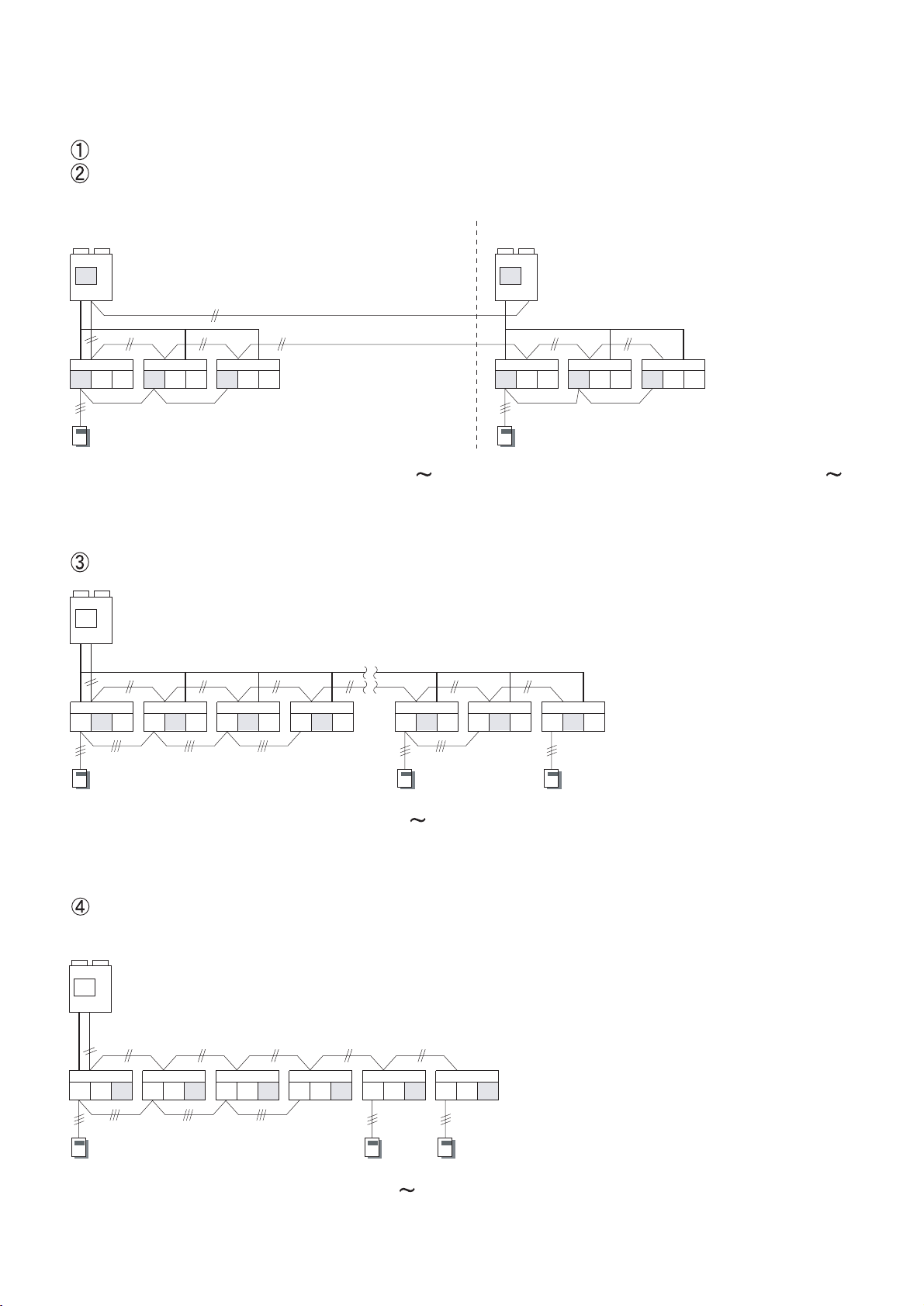
Refrigerant circuit address (Outdoor unit)
Refrigerant circuit address (Indoor unit)
Refrigerant circuit 1 Refrigerant circuit 2
1
00 01 02
1 1 10 1 2 2 2 20 1 2
Outdoor unit PCB (Address setting No.0
99) 99)
Setting by rotary SW8,9
2
00 01 02
Indoor unit PCB (Address setting No.0
Setting by rotary SW7,8
Indoor unit address
0
00 0 01 1 02 2 13 0 14 1 15 003
0 0 0 0 0 0 0
Indoor unit PCB (Address setting No. 0
15)
Setting by rotary SW5
Remote controller address
(Indoor unit)
0
00 0 01 1 02 2 0 03 3 0 04 0 0 05 0
0
Indoor unit PCB (Address setting No.0
0 0
15)
Setting by rotary SW9
– 16 –
Page 17

Remote controller switch 1
[Master] [Slave]
OFF
ON
Remote controller unit PCB
Setting by DIP SW 1-1
No. indoor unit connection
ON OFF
ON
Remote controller PCB
124
Setting by DIP SW 1-2
– 17 –
Page 18

Remote controller switch 2
(Remote controller)
[Master] [Slave]
Remote controller unit PCB
Setting by DIP SW 1-4
Central remote controller address
[Master] [Slave]
00
01
02
03
Central remote controller (Max.16)
Set central remote controller address first,to conduct the initial setting of it.
– 18 –
Page 19
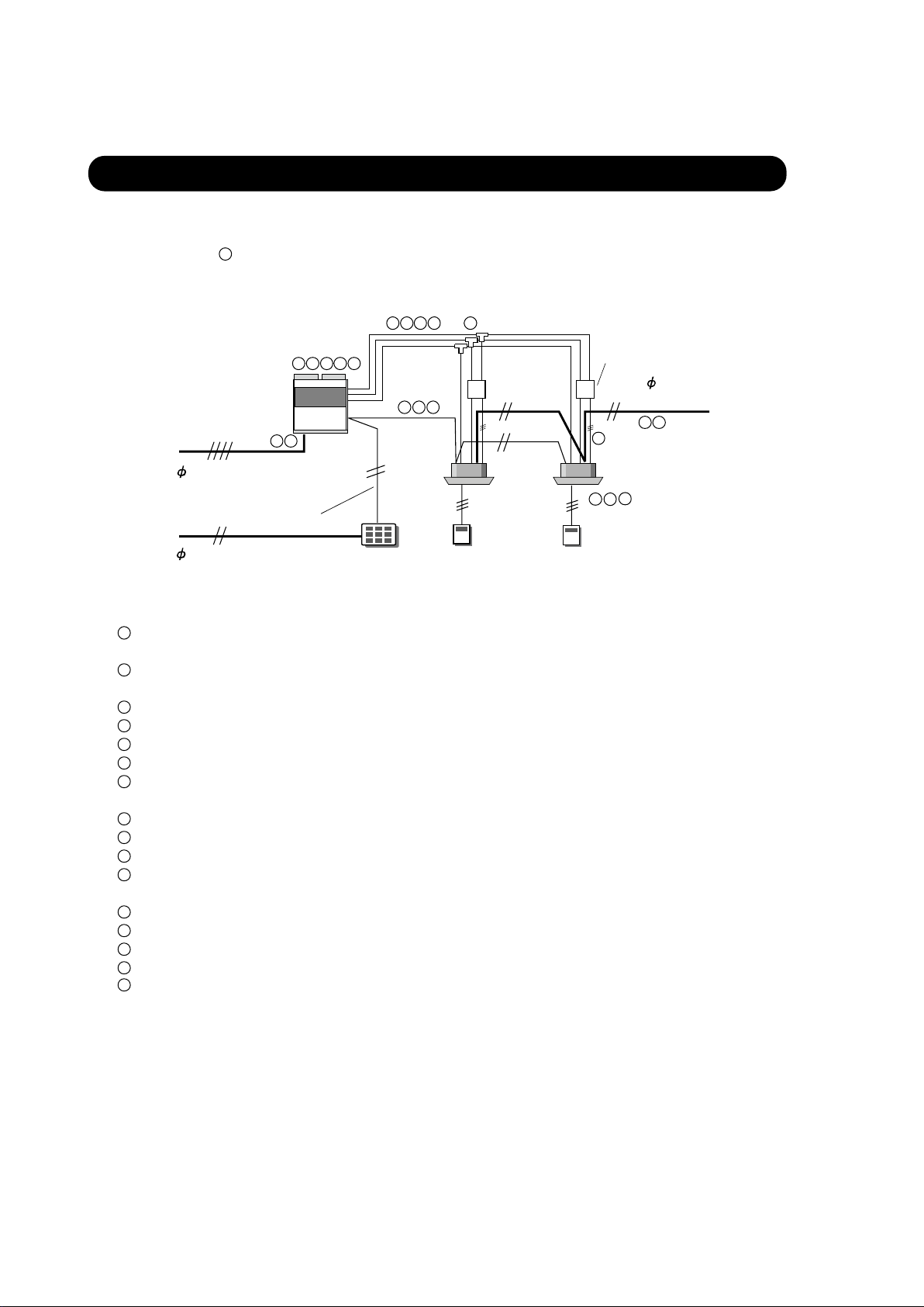
Outdoor
unit
3 4W 50Hz 380 - 415V
1 50Hz
220 - 240V
Transmission line
Indoor
unit
1
13
7 8
4
7
8
1
9
14 15 16
10 11
12
2
3 5 6
13
14
Central
remote controller
Wired
remote controller
RB unit
Before test running, check the following items.
Note: RB unit ( ) is for the heat recovery type.
Is the selection of the outdoor unit and the indoor unit correct?
(Maximum operating indoor unit, total capacity of the indoor unit)
Is the piping length correct?
(Ex. Maximum piping length : 100m)
Is the separate selected correct?
Doesn't gas leak?
Is the refrigerant flow correct?
Are the power supplies connected?
1
2
(Power supply for the indoor unit and outdoor unit is separated.)
Is the spec. for the power supply cable correct?
Is the RB unit cable connected?
Is the length of the transmission line under the limit?
Is the spec. for the transmission cable correct?
(non-polar 2-core, 0.75-1.25mm )
Is the transmission cable connected to all units?
2
Are the addresses set? (Ex. Refrigerant circuit address, indoor unit address, remote controller address, etc.)
Have the all settings done on the PCB?
Is the refrigerant valve opened?
Is the power supplied to crank case heater for 12 hours before winter operation?
3
4
5
6
7
8
9
10
Is the diameter of the pipe selected correct?
11
12
13
14
15
2-1 CHECK ITEMS BEFORE TEST RUNNING
9
2. TEST RUN
1 50Hz 220 - 240V
16
– 19 –
Page 20
2-2 TEST RUNNING METHOD
Supply power to the crankcase heater for 12 hours prior to the start of operation in the winter.
The following is the procedure for the test operation.
2-2-1 OUTDOOR PC BOARD
If the test operation is to be done for cooling operation, set DIP switch (SW-1-1) to on. If the test operation is to be done for heating,
set DIP switch (SW1-2) to on.
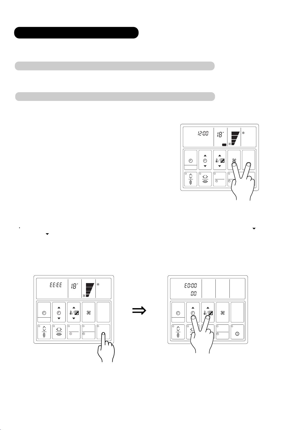
2-2-2 TEST OPERATION USING REMOTE CONTROLLER
(1) Standard wired remote controller
For test running, when the remote controller FAN CONTROL
button and MASTER CONTROL button are pressed simulta-
neously for more than three seconds when the air conditioner is
not running, the air conditioner starts and TEST is displayed on
the remote controller display.
However, the SET TEMP./DAY setting button does not function,
but all other buttons, displays, and protection functions operate.
CLOCK
NON STOP
SET TIME
TIMER
MODE
CLOCK ADJUST
TEST
TEMP./DAY
C
CONTROL
FAN
COOL
MASTER
CONTROL
When EE : EE blinks at the current time display, there
DAY button ( ) are pressed
simultaneously for more than three seconds, the self
be displayed at the current time display. In addition,
lights, press the START/STOP button and after
CLOCK
NON STOP
SET TIME
TIMER
MODE
CLOCK ADJUST
TEMP./DAY
C
CONTROL
FAN
COOL
MASTER
CONTROL
operation lamp goes off, perform the same operation.
ZONE
ENERG
SET
D
is an error inside the air conditioner. If the SET TIME
diagnosis check will start and the error
the remote controller address will be displayed below.
TIMER
MODE
CLOCK ADJUST
SET TIME
TEMP./DAY
FAN
CONTROL
MASTER
CONTROL
OP
SET
button ( ) and SET TEMP.
contents will
When the oper
ation
lamp
Stop operation
ZONE
SET
START/STOP
ENERGY SAVE
DAY OFF
– 20 –
ZONE
SET
SET
START/STOP
ENERGY SAVE
DAY OFF
Page 21

Error Code
Error contents
Error Code
Error contents
No error
Model information abnormal
Power supply frequency abnormal
EEPROM access error
EEPROM elimination error
Room temperature thermistor error
Indoor unit heat exchange thermistor
(middle) error
Indoor unit heat exchange thermistor
(inlet) error
Indoor unit heat exchange
(exit) error
thermistor
To stop test running, press the START/STOP button.
For the operation method, refer to the operating manual and perform operation check.
Check that there are no abnormal sounds or vibration sounds during test running.
(2) Standard wireless remote controller
Press the remote control unit test run button while the air condi tioner is running.
Blower temperature thermistor error
Drain abnormal
Room temperature abnormal
Indoor unit fan error
Communication error
Node setting error
Parallel communication error
Outdoor unit error
Remote control unit
At the end of test running, press the remote control unit start-
stop button.
Operation can be checked by lighting and flashing of the display
section OPERATION and TIMER lamps.
Perform judgment in accordance with the following.
Test running
When the air conditioner is run by pressing the remote control
unit test run button, the OPERATION and TIMER lamps flash
slowly at the same time.
START
STOP
A B C D
START/STOP button
TEST RUN button
– 21 –
Page 22

– 22 –
1) When the test run signal is transmitted from the standard wired remote controller, the wireless remote controller
and the central remote controller.
(1) In the test running status, operated in accordance with the setting of each switch besides the room temperature
switch. The room temperature adjustment does not funtion, and then the electric expansion valve is controlled
with maximum flow.
(2) De-frosting and de-icing prevention has priority over item(1).
(3) After 60 minutes passes, the test run stops.
2) When the test run signal is transmitted from the outdoor unit.
(1) Whether state of the indoor unit operates or stops, test run will be made in accordance with the operation
mode of the indoor unit , which belongs to the same refrigerant system.
(2) Test running initialization is shown below.
Air Flow Hi Hi
RoomTemperature Indication 18 30
Vertical Air Direction Panel
Horizontal Air Direction Panel
Swing
Operating Mode Cooling Heating
Initialized position Initialized position
Front Front
OFF
OFF
2-3 TEST RUN CONTROL
Page 23
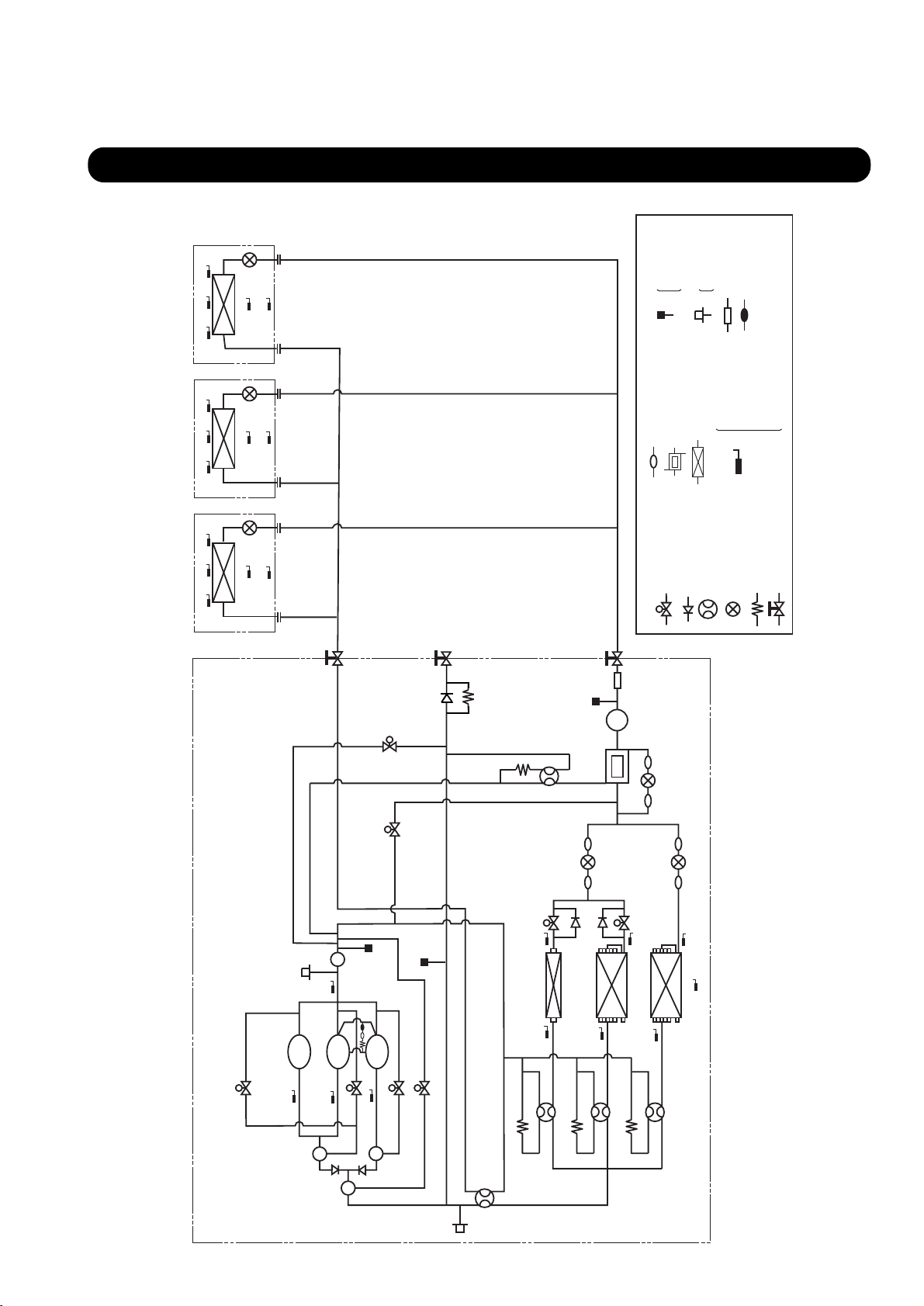
3.REFRIGERANT PIPE SYSTEM DIAGRAM
3-1 COOLING ONLY / HEAT PUMP TYPE
THOA
THHO THHM THHI
THOA
THHO THHM THHI
THOA
THHO THHM THHI
INDOOR UNIT A INDOOR UNIT B INDOOR UNIT C
EEV
EEV
EEV
HP:High pressure
MP:Middle pressure
LP:Low pressure
HP:High pressure
LP:Low pressure
:Oil sensor
:Dryer
:Pressure switch
THIATHIA THIA
:H.E. middle thermistor
:Outlet air thermistor
:H.E. outlet thermistor
:H.E. inlet thermistor
D
OA
HM
HO
Hi
BV1
SV2
BV2
4WV5
:Discharge thermistor
TH
:Heat exchanger
:Thermistor
:4-way valve
:Check valve
TH
:Expansion valve
:Strainer :Pressure sensor
:Power accumulation unit
:Solenoid valve
BV3
MP
TANK
RECEIVER
THs:Suction thermistor
TH
TH
TH
THR:Room temp thermistor
:Capillary tube
THo:Outdoor temp thermistor
THIA:Indoor Room temp thermistor
:Ball valve
OUTDOOR UNIT
SV3
EEV3
SV1
EEV1
SV7
LP
LP
CCUMU
A
LATEOR
THS
HP
THHO1
H.E.1
THHI1
COMP.1
COMP.2
COMP.3
SV4
THD1
THD2
OIL
SEPARATER
OIL
SEPARATER
THD3
SV6
SV5
4WV2
OIL
SEPARATER
4WV1
HP
SV8
THHO2
H.E.2
THHI2
4WV3
EEV2
THHO3
THO
H.E.3
THHI3
4WV4
– 23 –
Page 24
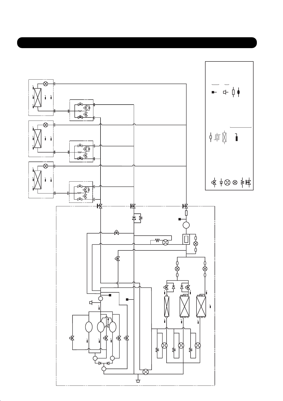
3-2 HEAT RECOVERY TYPE
EEV
THIA
THOA
THHO THHM THHI
EEV
THOA
THIA
THHO THHM THHI
R.B UNIT
R.B UNIT
SVD
SVB2
SVB1
SVs
SVD
SVB2
SVB1
SVs
HP:High pressure
MP:Middle pressure
LP:Low pressure
:Pressure switch
:Strainer :Pressure sensor
:Power accumulation unit
:Heat exchanger
HP:High pressure
LP:Low pressure
:Oil sensor
:Dryer
:H.E. middle thermistor
:H.E. outlet thermistor
:H.E. inlet thermistor
:Discharge thermistor
D
Hi
HO
HM
TH
TH
TH
TH
:Thermistor
:Outlet air thermistor
OA
THs:Suction thermistor
TH
THo:Outdoor temp thermistor
THR:Room temp thermistor
THIA:Indoor Room temp thermistor
THOA
THHO THHM THHI
INDOOR UNIT A INDOOR UNIT B INDOOR UNIT C
EEV
:Solenoid valve
:4-way valve
:Check valve
:Expansion valve
:Capillary tube
:Ball valve
THIA
SVD
R.B UNIT
SVB2
SVB1
SVs
4WV5
H.E.1
BV3
MP
TANK
RECEIVER
EEV3
EEV1
SV8
THHO2
H.E.2
EEV2
THHO3
H.E.3
THO
SV2
SV1
BV2
SV7
HO1
T
HP
BV1
LP
LP
CCUMU
A
LATEOR
THS
OUTDOOR UNIT
SV3
THHI1
COMP.1
COMP.2
COMP.3
SV4
THD1
THD2
OIL
SEPARATER
OIL
SEPARATER
THD3
SV6
SV5
4WV2
OIL
SEPARATER
4WV1
HP
THHI2
4WV3
THHI3
4WV4
– 24 –
Page 25
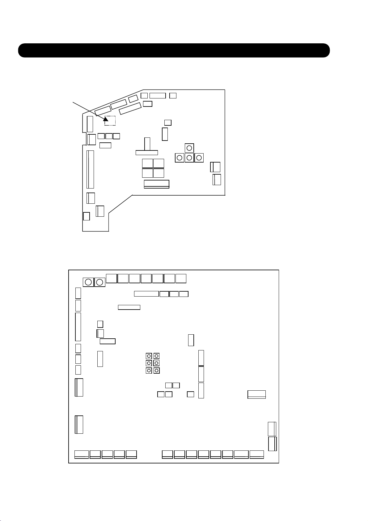
4. FUNCTION OF PRINTED CIRCUIT BOARD
4-1 PCB LAYOUTS
■
INDOOR UNIT CONTROL CIRCUIT BOARD
CN19 CN20 CN21
CN15
JM1-3
CN10
CN16
CN4
CN11
CN23
CN14
CN18
CN13 CN8
CN22
CN12
CN24
CN26
SW2
SW1
CN17
CN25
SW4
SW3
CN6
SW5
SW9SW7SW8
CN2
CN1
CN3
SW10
■
OUTDOOR UNIT CONTROL CIRCUIT BOARD
CN52
CN53
CN45
CN24
CN25
CN26
CN4
SW9 SW8
CN5
SW6SW7 SW5 SW4 SW3 SW2 SW1
CN27 CN3 4
CN51
CN2
CN22
CN44
CN28
LED4
LED5
LED6
EXT.
INPUT1
CN33
LED1
LED2
LED3
CN43 CN42
EXT.
INPUT2
CN32
CN48CN49CN50
CN35
CN29
CN30
CN31
CN1
CN3
CN21
CN20
CN19
CN18
CN17
CN14
CN12 CN10 CN8
CN13 CN11 CN9 CN7
– 25 –
CN5
CN6
Page 26
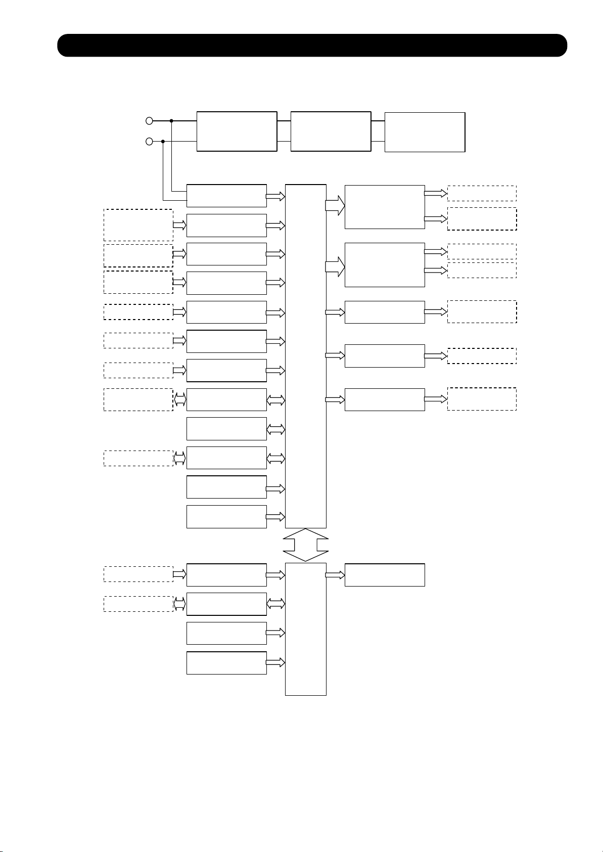
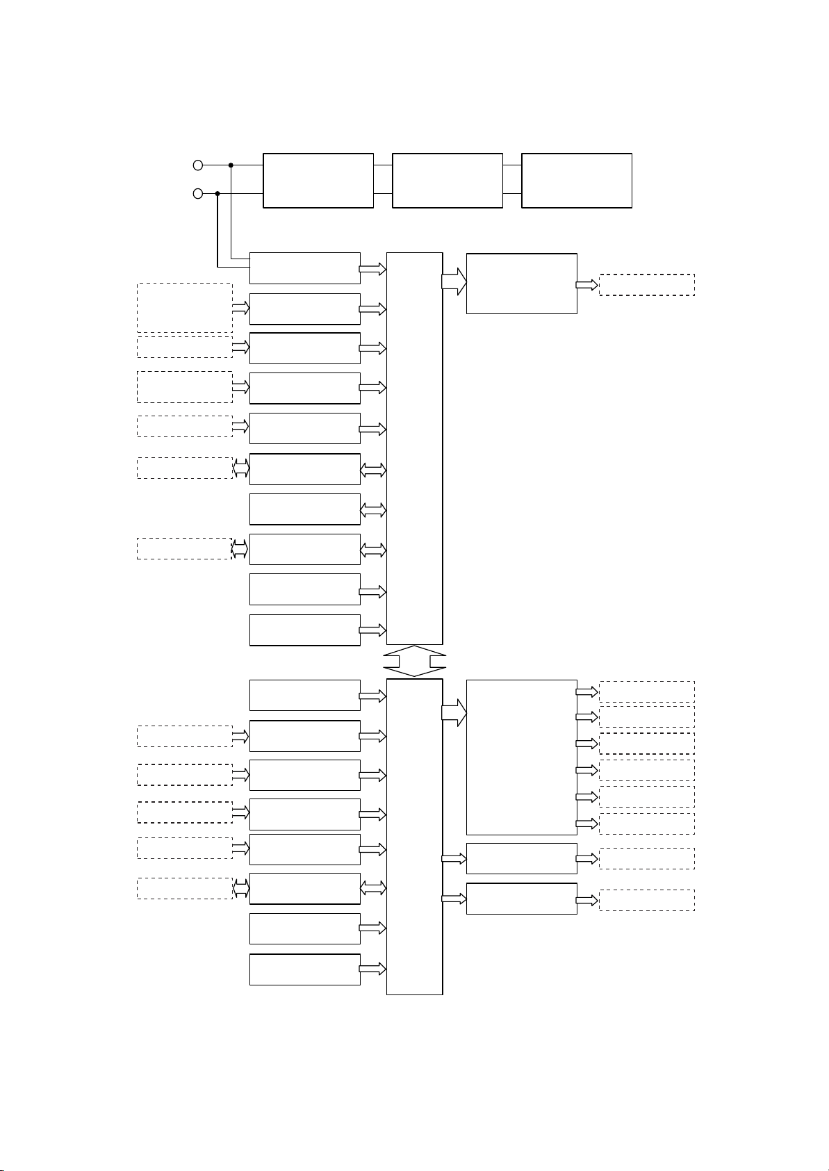
4-2 MICROPROCESSOR BLOCK DIAGRAM
INDOOR UNIT
■
Power supply
ROOM THERMISTER(CN19)
PIPE INLET/IMEDIATE
/OUTLET THERMISTER(CN20)
OUTLET THERMISTER(CN21)
FAN FEEDBACK
DIP SW(SW1-4)
ROTARY SW(SW5,7,9)
FLOAT SW(CN15)
COMMUNICATION
PWB.(CN26)
(CN16)
TEST(CN18)
(CN24)
FILTER CIRCUIT
POWER DETECTION
CIRCUIT
TEMPERATURE
DETECTION CIRCUIT
FAN ROTATION
READ CIRCUIT
SWITCH
READ CIRCUIT
FLOAT SWITCH
INPUT CIRCUIT
TEST INPUT
CIRCUIT
EXTERNAL INPUT
CIRCUIT
COMMUNICATION
CIRCUIT
RECTIFICATION
SMOOTHING
CIRCUIT
MICROPROCESSOR
DC-DC CONVERTER
5V,12V,14V
ACTUATOR
DRIVE CIRCUIT
SP MOTOR
DRIVE CIRCUIT
INDICATOR
DISPLAY OUTPUT
EXTERNAL OUTPUT
AUXILIARY
HEATER OUTPUT
FAN MOTER(CN4)
DRAIN PUMP(CN5)
SV(CN6)
LOUVER(CN10,CN11)
EEV(CN14)
INDICATOR
DISPLAY(CN13)
(CN22)
AUXILIARY
HEATER(CN12)
(CN24)
Wired remote
controller(CN17)
(CN25)
EEPROM
FLASH WRITE
CIRCUIT
RESET CIRCUIT
OSCILLATOR
CIRCUIT
WIRED REMOTE
CONTROLLER
READ CIRCUIT
FLASH WRITE
CIRCUIT
RESET CIRCUIT
OSCILLATOR
CIRCUIT
COMMUNICATION
BUZZER OUTPUT
MICROPROCESSOR
– 26 –
Page 27
OUTDOOR UNIT
■
Power supply
SUCTION/
OUTDOOR/
DISCHARGE
TEMP. 1-3(CN27)
PRESSURE
SENSOR(CN32-34)
DIP SW(SW1-7)
ROTARY SW(SW8,9)
TEST(CN35)
COMMUNICATION
PWB.(CN51)
(CN44)
FILTER CIRCUIT
POWER DETECTION
CIRCUIT
TEMPERATURE
DETECTION CIRCUIT
PRESSURE
DETECTION CIRCUIT
SWITCH
READ CIRCUIT
TEST INPUT
CIRCUIT
COMMUNICATION
CIRCUIT
EEPROM
FLASH WRITE
CIRCUIT
RECTIFICATION
SMOOTHING
CIRCUIT
MICROPROCESSOR
DC-DC CONVERTER
5V,12V,14V
ST MOTOR
DRIVE CIRCUIT
EEV (CN29-31)
WIRED REMOTE
CONTROLLER(CN17)
OIL SENSOR
SW(CN52,53)
PRESSURE
SW(CN49,50)
(CN49,50)
(CN28)
RESET CIRCUIT
OSCILLATOR
CIRCUIT
POWER DETECTION
CIRCUIT
TEMPERATURE
DETECTION CIRCUIT
OIL SENSOR
READ CIRCUIT
PRESSURE SWITCH
READ CIRCUIT
EXTERNAL
INPUT CIRCUIT
FLASH WRITE
CIRCUIT
RESET CIRCUIT
OSCILLATOR
CIRCUIT
COMMUNICATION
ACTUATOR
DRIVE CIRCUIT
LED OUTPUT
EXTERNAL OUTPUT
COMPRESSOR
(CN24-26)
FAN MOTOR(CN3,4)
4WYV(CN17-21)
SV(CN7-16)
BASE HEATER(CN5)
COMPRESSOR
(CN24-26)
LED(LED1-6)
(CN28)
MICROPROCESSOR
– 27 –
Page 28
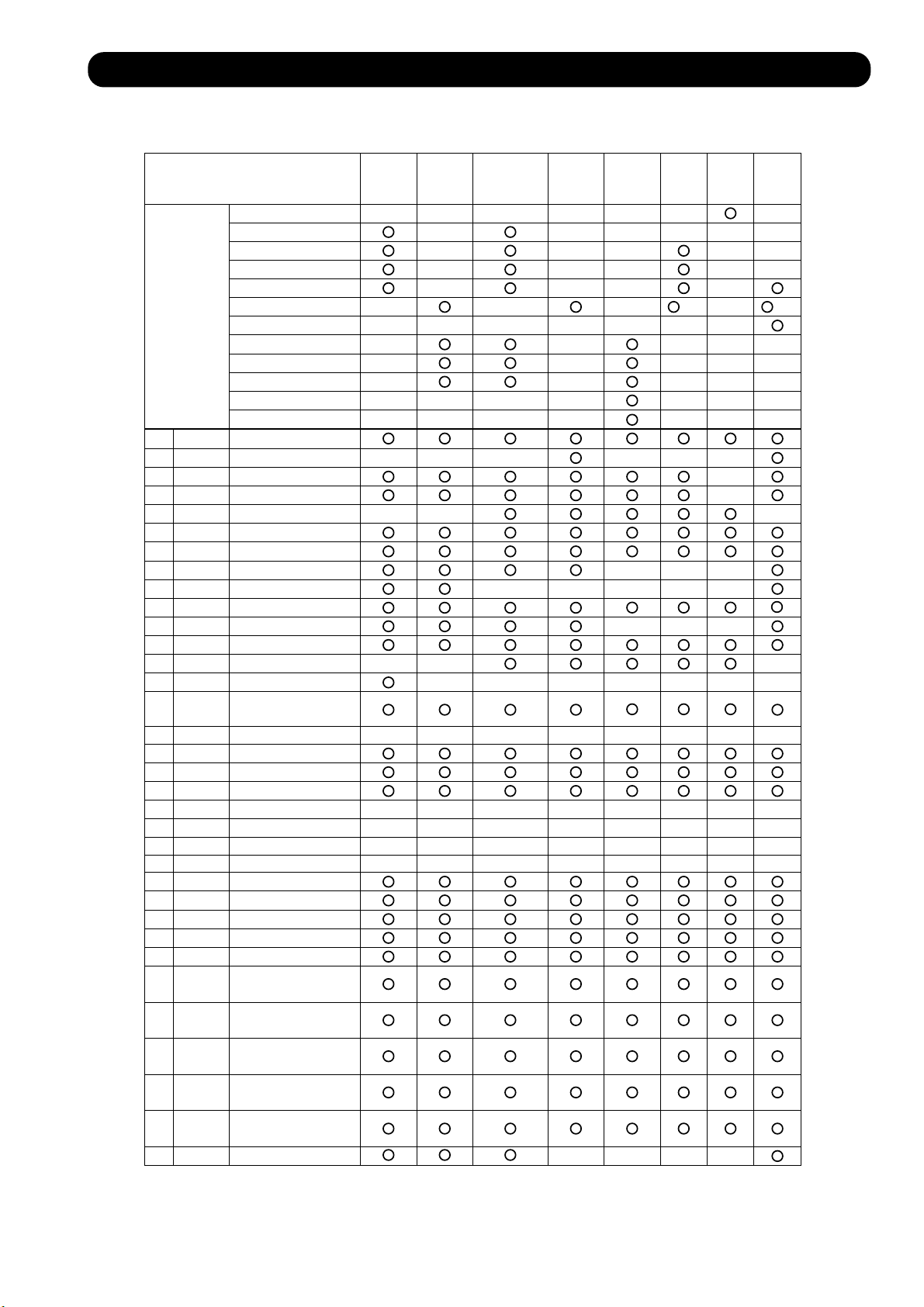
4-3 MICROPROCESSOR FUNCTION LIST
■ INDOOR UNIT
INDOOR UNIT TYPE
60,000
54,000
45,000
36,000
30,000
CAPACITY
(BTU/h)
24,000(25,000)
20,000
18,000
14,000
12,000
9,000
7,000
CN1 ACIN
CN2 TH FUSE
CN3 FAN CAPA
CN4 FAN MOTOR
CN5 DRAIN PUMP
CN6 S. VALVE
CN8 NETWORK
CN10 SP-M(U.D)
CN11 SP-M(R,L)
CN12
HEATER
CN13 DISPLAY
CN14 E.E.VALVE
CN15 FLOAT SW
CN16
CN17
FAN FEEDBACK
WIRED REMOTE
CONTROLLER
CN18 TEST
CN19 R.TH
CN20 P.TH
CN21 S.TH
CN22
CN23
EXT.OUTPUT
EXT.INPUT
CN24 FLASH(MAIN)
CN25 FLASH(SUB)
CN26 COMMUNICATE
SW1
SW2
SW3
SW4
SW5
SW6
SW7
SW8
SW9
SW10
FUNCTION 1
FUNCTION 2
FUNCTION 3
FUNCTION 4
INDOOR UNIT
ADDRESS 1
INDOOR UNIT
ADDRESS 2
REFRIGERANT
ADDRESS 1
REFRIGERANT
ADDRESS 2
REMOTE CONT-
ROLLER ADDRESS
MANUAL AUTO
Large
Ceiling
Universal
Compact
Cassette
Large
Cassette
Compact
Duct
Low
Duct
High
Static
Pressure
Duct
Static
Pressure
25 25
Wall
Mounted
– 28 –
Page 29

■ OUTDOOR UNIT
OUTDOOR UNIT TYPE
CN1 AC IN
CN2 NET
CN3 FAN.1
CN4 FAN.2
CN5 BASE HEATER
CN6 CRANK CASE HEATER
CN7 S.V.1
CN8 S.V.2
CN9 S.V.3
CN10 S.V.4
CN11 S.V.5
CN12 S.V.6
CN13 S.V.7
CN14 S.V.8
CN17 4WV.1
CN18 4WV.2
CN19 4WV.3
CN20 4WV.4
CN21 4WV.5
CN22 TERMINATOR
CN24 COMP.1
CN25 COMP.2
CN26 COMP.3
CN27 TH.1
CN28 FLASH W/R S
CN29 E.E.V.1
CN30 E.E.V.2
CN31 E.E.V.3
CN32 P.SEN-L
CN33 P.SEN-M
CN34 P.SEN-H
CN35 TEST
CN42 P.SW-H
CN43 P.SW-L
CN44 FLASH W/R M
CN45 TH.2
CN48 EXT.OUTPUT
CN49 EXT.INPUT2
CN50 EXT.INPUT1
CN51 COMMUNICATION
PWB.
CN52 OIL LV-HI
CN53 OIL LV-LO
SW1
SW2
SW3
SW4
SW5
SW6
SW7
SW8
SW9
FUNCTION 1
FUNCTION 1
FUNCTION 1
FUNCTION 1
FUNCTION 1
FUNCTION 1
FUNCTION 1
REFRIGERANT
ADDRESS 1
REFRIGERANT
ADDRESS 2
AOY90TPAMF
– 29 –
Page 30

4-4 FUNCTION AND SETTING OF EACH SWITCH
■ INDOOR UNIT
1. DIP SWITCH 1
1
Ceiling height setting.
Changeover the fan speed of the indoor fan phase control according to ceiling height (cassette type).
Details of rotation is according to DIP SW3 setting.
CEILING HEIGHT SETTING 1,2
Standard High ceiling 1 Low ceiling
SW1-1
SW1-2
(2)
NOTCH
Ceiling height
Room temp correct coefficient of heating.
2
Decide room temp correct coefficient value of heating.
ROOM TEMP. CORRECT COEFFICIENT OF HEATING
SW1-3
OFF
ON OFF - 2 deg
(3)
(4)
(5)
(6)
OFF
OFF OFF
HIGH(1)
MED
LOW LOW
S-LOW S-LOW S-LOW S-LOW
2.5 3.0m
SW1-4
OFF
ON
3.0 3.5m
Coefficient value
High ceiling 2
ON
HIGH HIGH
MED MED
+ 2 deg
0 degOFF
OFF
ON ON
LOW
more than
3.5m
ON
HIGH
MEDLOW
less than
2.5m
+ 4 degON ON
2. DIP SWITCH 2
Room temp. correct coefficient of cooling.
1
Decide room temp correct coefficient value of cooling.
ROOM TEMP CORRECT COEFFICIENT OF COOLING
SW2-1
OFF
ON + 2 deg
2
Zone control switch.
Decide the indoor unit for zone control use and not for zone control.
ZONE CONTROL SWITCH
SW2-2
OFF
ON
Coefficient value
0 deg
Switch control
Validity
Invalidity
Ð 12Ð
– 30 –
Page 31

3
Filter check validity/invalidity.
Filter check is set with Dip SW 2-3.
FILTER CLEANING FUNCTION
SW2-3
Filter check
OFF
ON
4
Auto restart validity/invalidity.
Invalidity
Validity
Auto restart is set with Dip SW2-4. But,when a LCD wired remote controller
is connected, auto restart is set to "validity" regardless of the indoor unit setting.
AUTO RESTART SETTING
SW2-4
OFF
ON
Auto restart
Invalidity
Validity
3. DIP SWITCH 3
Indoor unit for speed switch.
1
This switch has eight kinds of rotation table, and can select fan speed corresponding to each model.
INDOOR UNIT FAN SPEED TABLE
Table No.
SW3-2
SW3-3 OFF
0 1 3
OFF
ONSW3-1
OFF OFF
OFF
OFF OFF
2 4 75
OFF
ON ON
ON
OFF
OFF
ON
ON
OFF
ON
6
OFF
ON
ON
ON
ON
ON
INDOOR FAN MOTOR SPEED (LARGE CEILING)
Table No.
Models
Hi
Me
Lo
S-Lo
0 1 3
AB30
Not used
750
600
500 500
2 4 75
AB36
1000850
900
750
Not used Not used Not used
AB45
1100
1000
850
500
Rotating speed of the indoor fan motor is the same for Cooling / Fan / Heating.
6
AB54
1250
1150
1000
500
Ð 12Ð
– 31 –
Page 32

INDOOR FAN MOTOR SPEED (CASSETTE)
Table No.
Models
(1)
(2)
(3)
(4)
(5)
(6)
Models
(1)
(2)
(3)
(4)
(5)
0
AU54
680
630
580 550
550 500
500 470
300 300
4
AU30
500
470
430
390
360
AU45
620
580
Not used
1 2
AU36
580
550
500
470
420
300
5 6
AU25
460
430
390
350
320
3
Not used
7Table No.
AU20
420
390
350
310
280
(6)
*
2
Not used (SW3-4).
Rotating speed of the indoor fan motor is the same for Cooling/Fan/Heating.
300
4. DIP SWITCH 4
Indoor unit model switch.
1
Indoor unit model (capacity data) is set with SW4-1 4.
INDOOR UNIT MODEL SWITCH
Capacity
Type
SW4-1
SW4-2 OFF
SW4-3
90
OFF
ON
ON
60
ON
ON
OFF
ON
54
OFF
ON
OFF
ON
45
ON
OFF
OFF
ON
36
OFF
OFF
OFF
ON
30
ON
ON
ON
OFF
25
OFF
ON
ON
OFF
20
ON
OFF
ON
OFF
300
OFF
OFF
OFF
18
ON
14
ON
ON
OFF
OFF
12
OFF
ON
OFF
OFF
250
9
ON
OFF
OFF
OFF
7
OFF
OFF
OFF
OFFSW4-4
Ð 12Ð
– 32 –
Page 33

5. JUMPER
Custom code selection of the remote controller.
1
Custom code of the infrared signal is set with jumper lead combinations which are shown below.Once set, other infrared
signal is not accepted.
REMOTE CONTROLLER CUSTOM CODE SELECTION
JP1 JP2
Custom code
2
Not used (JP3)
Connect
Disconnect
Connect
Disconnect
Connect
Connect
Disconnect
Disconnect
Type A (Primary setting)
Type B
Type C
Type D
Ð 12Ð
– 33 –
Page 34

■ OUTDOOR UNIT
1. DIP SWITCH 1
1
Test run.
Test run(forced operation) and normal operation are set with SW1-1.2 on the PCB.
The cooling/heating operation mode on the test run is set.
TEST RUN SW
SW1-2 SW1-1 Test Run Remarks
OFF OFF Normal operation
OFF ON Cooling test run
ON OFF Heating test run
ON ON Normal operation
Pump down operation.
2
Pump down operation is set with SW1-3 on the PCB.
(OFF-ON)and (operated continuously
more than 1 min. with ON state)
(OFF-ON)and (operated continuously
more than 1 min. with ON state)
( Initial setting)
PUMP DOWN SW
SW1-3 Pump down operation Remarks
OFF Release
ON Operate
Forced defrost operation.
3
Defrosting is started forcedly with SW1-4 on the PCB.
FORCED DEFROST SW
SW1-4 Forced defrost Remarks
OFF Release
ON Operate
(OFF-ON)and (operated continuously
more than 1 min. with ON state)
(OFF-ON)and (operated continuously
more than 1 min. with ON state)
( Initial setting)
( Initial setting)
2. DIP SWITCH 2
Night operation fan mode.
1
The night operation fan mode ON/OFF is set with SW2-1 thermistor
detects the temperature less than 30 C and the outdoor unit operation mode is cooling.
NIGHT OPERATION FAN MODE SW
SW2-1
OFF
ON Operate
Snow falling protection fan mode SW.
2
When the compressor is stopped,snow falling protection fan mode is set with SW2-2.
SNOW FALLING PROTECTION FAN MODE SW
SW2-2
OFF
ON Operate
Night operation fan mode
Release
Snow falling protection fan mode
Release
( Initial setting)
( Initial setting)
– 34 –
Page 35

Expansion valve initialize.
3
The pulse of the expansion valve is initialized with SW2-3.
EXPANSION VALVE INITIALIZATION SW
SW2-3
OFF
ON Operate
Forced oil recovery operation.
4
Forced oil recovery operation started with SW2-4.
Expansion Valve Initialization
Operation
Release
( Initial setting )
Remarks
FORCED OIL RECOVERY SW
SW2-4
OFF
ON
Forced Oil Recovery
Release
Operate
3. DIP SWITCH3 SETTING IS FORBIDDEN
4. DIP SETTING IS FORBIDDEN
5. DIP SWITCH5
SW5-1 and SW5-2 setting are forbidden.1
2
Base heater validity/invalidity.
The base heater setting is performed with SW5-3.
BASE HEATER SETTING SW
SW5-3
OFF
ON Invalidity
Base Heater Setting SW
Validity
6. DIP SWITCH6 SETTING IS FORBIDDEN
( Initial setting )
Remarks
(OFF-ON)+(ON continues for 1 minute)
( Initial setting )
Remarks
7. DIP SWITCH7
System type switch 1,2.
1
Model change in Heat recovery / Heat pump type / Cooling only type are made with SW7-1,2.
SYSTEM TYPE SWITCH 1/2
SW7-1 Model selectionSW7-2
OFF
OFF
ON
ON
OFF
ON
OFF
ON
Heat Pump
Cooling Only
Heat Recovery
Cannot Set
( Initial setting )
Remarks
8. External input terminal 1/2
When the cooling or heating mode is selected, the priority circuit is set.
With CN49 and CN50.
EXTERNAL INPUT TERMINAL 1/2
Terminal
External input
terminal 1CN50
External input
terminal 2CN49
Conditions
R.C.
External input
Cool
Heat
Setting
OPEN
SHORT
OPEN
SHORT
Remarks
– 35 –
Page 36

■ WIRED REMOTE CONTROLLER
1. DIP SWITCH 1
1
Remote controller address 1
FINAL REMOTE CONTROLLER SWITCH
SW1-1
Terminator
OFF
ON YES
2
Indoor unit connection.
This is switched according to No. of connected indoor unit.
No. INDOOR UNIT CONNECTION SWITCH
SW1-2
OFF
ON Multiple unit connection
Remote controller address1,2.
3
Used for setting of the remote controller address. Set the addresses by ordering MASTER SLAVE
without any space.
REMOTE CONTROLLER ADDRESS 1,2 SWITCH
SW1-3 SW1-4
OFF
OFF ON Slave
Number of indoor unit
One unit connection
OFF Master
NO
Method
SW1-5 and SW1-6 setting are forbidden.4
2. DIP SWITCH 2
Cooling only / heat pump.
1
Switching cooling only / heat pump is set with SW2-1.
COOLING ONLY / HEAT PUMP SWITCH
SW2-1
OFF
ON Cooling only
2
Auto change over validity / invalidity.
Auto change over validity / invalidity is set with SW2-2.
AUTO CHANGEOVER SWITCHING
SW2-2
OFF
ON Validity
Operation system
Heat pump
Auto restart
Invalidity
Ð 12Ð
– 36 –
Page 37

3
SW2-3 setting is forbidden.
4
Maintenance.
Used for indication of the refrigerant system, indoor unit address and error history.
MAINTENANCE SWITCH
SW2-4
Mode
OFF
ON Maintenance mode
5
SW2-5 setting is forbidden.
6
Battery backup switch.
When installing, turn the SW2-6 ON.
Normal mode
Ð 12Ð
– 37 –
Page 38

■ CENTRAL REMOTE CONTROLLER
1. DIP-SW2
DIP SW2-1 2-2 setting forbidden.
1
DIP SW 2-1 OFF
DIP SW 2-2 OFF
DIP SW2-3 setting.
2
Filter check sign indication or not when filter check comes from indoor unit.
( Factory setting)
SW2-3
Filter check sign indication
OFF
ON Display
DIP SW2-4 setting.
3
C / F switch
Temperature display is centigratde( ) / Fahrenheit( )
SW2-4
OFF
ON
DIP SW2-5 setting
4
For validity / invalidity the wired and wireless remote controller operation prohibit function.
SW2-5
OFF
ON Invalidity
DIP SW2-6 2-7 setting forbidden.
5
Non-Display
C
( Factory setting)
C / F
C
F
( Factory setting)
RC operation prohibit function
Validity
F
DIP SW 2-6 OFF
DIP SW 2-7 OFF
DIP SW2-8 setting.
6
SRAM Battery ON / OFF
When installing the control remote controller, this switch must be set to ON.
(factory setting:OFF)
( Factory setting)
SW2-8
OFF
ON
At the time of shipment,the battery is turned off to avoid electricity consumption.
Be sure to set this switch to ON.
7
SW42 Initial setting button
This switch is used when initializing the central remote controller.
SRAM Battery
OFF
ON
– 38 –
Page 39

WIRED REMOTE CONTROLLER
■
Display panel
TURE OF CONTROLLER
FEA
Four kinds of timer setup (OFF/ ON1/ ON2/ WEEKLY) are
possible.
NON STOP
OFFON
TIMER
WEEKLY
12
TIMER
MODE
CLOCK ADJUST
CLOCK
TIMER
NEXT DAY
SET TIME
OFF
ON
ON
OFF
CENTRAL
DAY OFF
DEFROST
TEMP./DAY
ZONE
SET
C
F
DAY
TEST
FAN
CONTROL
ENERGY SAVE
DAY OFF
AUTOAUTO
COOL
DRY
FAN
HEAT
ANTI FREEZE
MASTER
CONTROL
START/STOP
Equipped with weekly timer as standard function.
(2 times Start/Stop per day for a week)
By failure,the error code is displayed. The error history
can be displayed,which is convenient for maintenance.
2 remote controllers can be connected.
Up to 16 indoor units can be simultaneously controlled.
Anti freeze, saving operation and zone control are possible.
Favorite timer ( ON 2 )
■
FUNCTIONS
15
Display
CLOCK
14
13
12
11
10
9
8
7
NON STOP
OFFON
TIMER
WEEKLY
12
NON STOP
OFFON
TIMER
WEEKLY
12
TIMER
MODE
CLOCK ADJUST
19
CLOCK
TIMER
NEXT DAY
CENTRAL
OFF
ON
TIMER
ON
DAY OFF
OFF
DEFROST
NEXT DAY
SET TIME
TEMP./DAY
ZONE
SET
20 21 22 23
CENTRAL
OFF
ON
ON
DAY OFF
OFF
DEFROST
DAY
TEST
DAY
F
C
FAN
CONTROL
ENERGY SAVE
DAY OFF
C
F
TEST
AUTOAUTO
COOL
DRY
FAN
HEAT
ANTI FREEZE
MASTER
CONTROL
START/STOP
AUTOAUTO
COOL
DRY
FAN
HEAT
ANTI FREEZE
2426 252728
16
17
18
1
START/STOP button
Pressed to start and stop operation
2
Operation lamp
Lights during operation and when the timer is on.
3
Energy save button
Turns the energy efficient mode on and off.
4
Day off button
Temporary cancellation of one day timer.
5
Energy save lamp
Lights up when the unit is in the energy save mode.
6
1
2
3
4
5
6
Zone button
Use to turn the zone control on and off.
7
Set button
Sets the date, hour, minute and on-off time.
8
Zone lamp
Lights up when the unit is in the zone control mode.
9
Horizontal air flow direction and swing button
Push for two seconds and change swing mode.
10
Horizontal swing lamp
Push for two seconds and change swing mode.
11
Vertical air flow direction and swing button
Push for two seconds and change swing mode.
12
Vertical swing lamp
13
Clock adjust button
Timer mode button
14
Changes the timer mode (NON STOP, OFF TIMER,
ON TIMER, WEEKLY TIMER).
15
Set time button
Sets the current time and on-off time.
16
Temp./Day button
Sets the indoor temperature / days.
17
Fan control button
Selects the fan speed (AUTO, LOW, MED, HIGH).
18
Master control button
Selects the operating mode(AUTO, HEAT, FAN, COOL, DRY).
Clock display
19
20
Central control display
21
Set temperature / Day display
Fan speed display
22
Master control display
23
24
Anti freeze display
25
Day off display
Test display
26
27
Defrost display
28
Timer mode display
– 39 –
Page 40

WIRELESS REMOTE CONTROLLER
■
TURE OF CONTROLLER
FEA
C
L
O
C
K
TIM
ER
S
L
E
O
N
AM
O
F
H
M
PM
T
IM
E
R
R
E
S
E
O
F
F
O
N
E
N
E
R
G
Y
S
A
V
E
A
U
T
O
A
U
C
C
O
O
L
H
IG
D
R
Y
M
E
LO
FA
N
H
E
A
T
A B C D
A B C D
■
FUNCTIONS
Display
3
2
1
9
10
11
Display panel
15
CLOCK
16
AM
PM
OFF
AUTO
COOL
DRY
FA
HEAT
E
P
F
T
T
O
H
D
W
C
L
O
C
K
AM
PM
O
F
F
AUTO
C
O
O
L
DR
Y
FA
N
H
E
A
T
ON
ENERGY SAVE
N
Four kinds of timer setup (ON/OFF/PROGRAM/SLEEP)
are possible.
Up to 16 indoor units can be simultaneously controlled.
Both wired and wireless remote controller can be used jointly.
TIMER
S
L
E
E
P
O
N
O
F
F
H
M
T
IM
E
R
R
E
S
E
T
O
N
ENERGY SAVE
AUTO
C
H
IG
H
M
ED
L
O
W
12
13
A B C D
TIMER
14
SLEEP
ON
HM
OFF
TIMER RESET
AUTO
C
HIGH
MED
LOW
18
19
20
1
5
64
START/STOP button
Pressed to start and stop operation
2
Set temp./Set time buttons
Sets the indoor temp./Sets the current time and on-off time
3
Master control button
Selects the operating mode(AUTO, HEAT, FAN, COOL, DRY).
4
Sleep timer button
Press to select sleep timer.
5
Signal transmitter
6
7
Timer button
Press to select the timer mode.(OFF TIMER,ON TIMER,
.
PROGRAM TIMER,TIMER RESET)
7
Fan control button
8
Selects the fan speed (AUTO, LOW, MED, HIGH).
8
Battery compartment lid
9
Air flow direction button
Use to set the desired air flow direction & SWING
function.
10
Energy save button
Turns the energy efficient mode on and off.
11
Code change (Slide Switch)
Switching the remote control unit code.(Max.4 units)
12
Time adjust button
Set the current time.
13
Test run button
This button is used when testing the air conditioner
after installation.
14
ACL button
This button is used when replacing batteries.
15
Transmit indicator
Clock display
16
17
Master control display
18
Timer mode display
Fan speed display
19
20
Set temperature display
Timer set indicator
21
22
Temperature set indicator
17
21
22
– 40 –
Page 41

CENTRAL REMOTE CONTROLLER
SETTINGMONITOR MEMORY
ERROR
SUN SATFRITHU
WED
TUE
MON
AM
CLOCK
PM
ADDRESSADDRESS
AM
NON STOP
PM
ON
OFF
TIMER
AM
12
PM
WEEKLYWEEKLY
■
FEATURE OF CONTROLLER
NEXT DAYNEXT DAY
0
00 01 02 03 04 05 06 07 08 09 10 11 12 13 14 15 16 17 18 19
20 21 22 23 24 25 26 27 28 29 30 31 32 33 34 35 36 37 38 39
1
ONON
OFFOFF
40 41 42 43 44 45 46 47 48 49 50 51 52 53 54 55 56 57 58 59
2
60 61 62 63 64 65 66 67 68 69 70 71 72 73 74 75 76 77 78 79
OFFOFF
3
80 81 82 83 84 85 86 87 88 89 90 91 92 93 94 95 96 97 98 99
x100
ALL/GROUP
SELECT
TEST
CENTRAL CONTROL
ALL
X
100
Up to 400 indoor units/64 groups can be controlled with one central remote controller.
Up to 16 central remote controllers can be connected in one system.
Central remote controller can control by all/group/individual.
By setting the central remote controller, it is possible to lock the function of the standard
controllers. Items of selections are all functions, timer mode, disabling all functions for
certain hour, operating mode, temperature setting, reset filter, and On/Off.
Weekly timer is equipped as standard function. (2 times On/Off per day for one week).
Setting contents of central remote controller are all memorized, so that each indoor unit can
be operated in the memorized condition even if the operating conditions are changed later on.
Error code is displayed when it occurs.
The history of failure can also be displayed, which is convenient for maintenance.
FILTER
ZONE
ON OFF
ALL
OFFON
TEMP
F
C
ENERGY
SAVE
ON OFF
LOUVER
OPERATION
ON
OFF
AUTO
AUTO
COOL
DRY
FAN
HEAT
FIXED
ANTI
FREEZE
ON OFF
DEFROST
Examples of error:
1. Communication/micro computer error
2. Abnormal heat exchanger thermistor
3. Float switch operating
4. Abnormal outdoor unit thermistor
5. Abnormal discharge temperature
6. Abnormal oil sensor
7. Excessive indoor units connected
8. Abnormal indoor fan
■
FUNCTION
32
31
30
29
28
27
26
25
24
SUN SATFRITHU
MON
CLOCK
ADDRESSADDRESS
NON STOPNON STOP
OFF
TIMER
12
WEEKLYWEEKLY
CLOCK
ADJUST
TIMER
MODE
TIMER
COPY
9. Abnormal room temperature thermistor
10. Abnormal air blow temperature thermistor
11. 3 phase reverse polarity connection
12. Abnormal pressure
13. Abnormal refrigerant pressure sensor
14. Duplicated indoor unit address
15. Duplicated outdoor unit address
Display
133
SETTINGMONITOR MEMORY
ERROR
TEST
SET
CHECK
CENTRAL CONTROL
ALL
TEST
WED
TUE
AM
PM
AM
PM
ON
AM
PM
DAY
DAY OFF
NEXT DAYNEXT DAY
0
0000 0101 0202 0303 0404 0505 0606 0707 0808 0909 1010 1111 1212 1313 1414 1515 1616 1717 1818 1919
2020 2121 2222 2323 2424 2525 2626 2727 2828 2929 3030 3131 3232 3333 3434 3535 3636 3737 3838 3939
1
ONON
OFFOFF
4040 4141 4242 4343 4444 4545 4646 4747 4848 4949 5050 5151 5252 5353 5454 5555 5656 5757 5858 5959
2
6060 6161 6262 6363 6464 6565 6666 6767 6868 6969 7070 7171 7272 7373 7474 7575 7676 7777 7878 7979
OFFOFF
3
8080 8181 8282 8383 8484 8585 8686 8787 8888 8989 9090 9191 9292 9393 9494 9595 9696 9797 9898 9999
x100
ALL/GROUP
SELECT
X
100
TIME
TIMER
DELETE
TIMER
SET
MEMORY
OPERATION
MEMORY
SETTING
CENTRAL
CONTROL
GROUP
SETTING
BACK
DELETE
ZONE
FILTER
RESET
FILTER
ZONE
ON OFF
ALL
OFFON
ENERGY
SAVE
ON OFF
TEMP
F
C
ENERGY
SAVE
ON OFF
LOUVER
OPERATION
ON
OFF
TEMP.
AUTO
FAN
CONTROL
AUTO
COOL
DRY
FAN
HEAT
FIXED
ANTI
FREEZE
ON OFF
DEFROST
MASTER
CONTROL
ANTI
FREEZE
2
3
4
5
6
7
8
9
20
21
2223
19
18
1617
15
14
13
12
11 10
– 41 –
Page 42

1
All ON/OFF button
2
All ON/OFF LED
3
Back button
4
Zone button
5
Energy save button
6
Fan control button
7
Master control button
8
Anti freeze button
9
Horizontal Air flow direction and swing button
10
Vertical Air flow direction and swing button
11
Temp button
12
ON/OFF button
13
Filter reset button
14
Delete button
15
Test button
16
Set button
17
Set LED
18
Check button
19
Group setting button
20
Memory setting button
21
Timer set button
22
Time button
23
Day off button
24
Timer copy button
25
Timer mode button
26
Clock adjust button
27
Day button
28
Timer delete button
29
Memory operation button
30
Central button
31
All/Group button
32
Select 100 button
33
Select button
Change over the zone.
Starting energy save operation.
Setting of indoor temperature.
ON/OFF setting by groups.
Delete of setting.
Transmission of all changed setting details.
Blinks when transmission is necessary.
Confirmation of address setting and error code.
Setting of group of some remote controller group connected to the central remote controller.
Memory the setting contents of all.
Setting of dates, hours, minutes and on-off time.
Setting of on-off time.
Temporary cancellation of one day timer.
Copying the timer condition (the day before).
Changeover the timer mode (NON STOP, OFF, ON1, ON2, WEEKLY).
Operating the memorized condition.
Forbid some operation of the individual remote controller.
Changeover of control unit (ALL GROUP R.C.GROUP).
Remote controller group indication by hundreds.
Change to remote controller and group number.
Display panel
SUN SATFRITHU
TUE
MON
AM
52
CLOCK
PM
ADDRESSADDRESS
AM
NON STOPNON STOP
PM
ON
OFF
TIMER
AM
12
PM
WEEKLYWEEKLY
51
34
Day of the week display
35
Status display
36
Transmit indicator display
37
Central control display
38
Filter reset display
39
Zone display
WED
NEXT DAY
50
ERROR
36
TEST
CENTRAL CONTROL
ALL
3534
SETTINGMONITOR MEMORY
0
0000 0101 0202 0303 0404 0505 0606 0707 0808 0909 1010 1111 1212 1313 1414 1515 1616 1717 1818 1919
2020 2121 2222 2323 2424 2525 2626 2727 2828 2929 3030 3131 3232 3333 3434 3535 3636 3737 3838 3939
1
ONON
OFFOFF
4040 4141 4242 4343 4444 4545 4646 4747 4848 4949 5050 5151 5252 5353 5454 5555 5656 5757 5858 5959
2
6060 6161 6262 6363 6464 6565 6666 6767 6868 6969 7070 7171 7272 7373 7474 7575 7676 7777 7878 7979
OFFOFF
3
8080 8181 8282 8383 8484 8585 8686 8787 8888 8989 9090 9191 9292 9393 9494 9595 9696 9797 9898 9999
x100x100
49 48
40
Temperature display
41
Energy save display
42
Fan control display
43
Master control display
44
Fixed cooling or heating
operation display
45
46
47
48
49
50
– 42 –
38
FILTER
ZONE
ON OFF
40
39
TEMP
ENERGY
SAVE
ON OFF
OPERATION
ON
OFF
37
Anti freeze display
Defrost display
Air flow direction display
ON/OFF display
Group control display
ON/OFF time display
F
C
LOUVER
43
4241
AUTO
AUTO
COOL
DRY
FAN
HEAT
FIXED
ANTI
FREEZE
ON OFF
DEFROST
47
46
51
Timer mode display
52
Clock and address
display
44
45
Page 43

5. OUTDOOR UNIT OPERATION CONTROL
5-1 COMPRESSOR OPERATION CONTROL
5-1-1 OPERATION STOP CONDITION
Compressor operation condition
When cooling requirement capacity or heating requirement capacity from either of the indoor units in the same
refrigerant system is input, the compressor operates.
But in the following case, the compressor operates in accordance with operation of each mode.
During 3 minute restart prevention operation
During compressor recovery operation
During deicing operation
Failure ( except for a part )
Defrosting
4-way valve 1 restart switching
Oil recovery
Under expansion valve initialization
At protective operation
Central discharge temperature protection
High pressure protection
Compressor stop condition
When all the indoor units in no "cooling requirement capacity" or "heating requirement capacity ",
are stopped.
But, in the following case, the compressor operates in accordance with operation of each mode.
all the compressors
Defrosting
Oil recovery
5-1-2 COMPRESSOR OUTPUT PATTERN
The output pattern of a compressor is defined as shown below.
Compressor output pattern
OUTPUT PATTERN
Step 0
Step 1
Step 2
Step 3
Step 4
Step 5
Step 6
Step 7
COMPRESSOR 1
(2HP)
OFF
ON
OFF
ON
OFF
ON
OFF
ON
COMPRESSOR 2
(4HP)
OFF
OFF
ON
ON
OFF
OFF
ON
ON
5-1-3 3 MINUTES RESTART PREVENTION (3 MIN ST)
COMPRESSOR 3
(6HP)
OFF
OFF
OFF
OFF
ON
ON
ON
ON
When the compressor is stopped, the compressor does not start on any condition for 3 minutes afterwards.
But, this function is excluded when defrosting, oil recovery is performed and the power is turned on.
– 43 –
Page 44

5-1-4
If compressor 1, 2, or 3 fails, or if two or more compressors fail at the same time, the remaining compressor(s)
perform temporary operation to prevent interruption of air conditioning system operation by a failure.
When compressor 1, 2, or 3 is judged to be faulty, the system is operated by switching the compressor output
pattern (compressors 0 to 7) as shown in the following table.
Compressor failure is displayed by LEDs on the PCB of the outdoor unit and by output ERROR to the
communication bus line (standard wired remote controller, central remote controller, PC controller).
(a) When compressor 1 (2 HP) fails (compressor 2 is substituted for compressor 1).
(b) When compressor 2 (4 HP) fails (compressor 3 is substituted for compressor 2)
(c) When compressor 3 (6 HP) fails (compressor 1 and 2 are substituted for compressor 3)
COMPRESSOR RECOVERY OPERATION
ORDINARY OPERATION
COMPRESSOR RECOVERY OPERATION
RECOVERY OPERATION
(a)X-4-6 (b)2-X-6 (c)2-4 X
Step 0
Step 1
Step 2
Step 3
Step 4
Step 5
Step 6
Step 0
Step 2
Step 2
Step 4
Step 6
Step 6
Step 6
Step 0
Step 1
Step 4
Step 4
Step 5
Step 5
Step 5
Step 0
Step 1
Step 2
Step 3
Step 3
Step 3
Step 3
(d)X-X-6
Step 0
Step 4
Step 4
Step 4
Step 4
Step 4
Step 4
(e)X-4-X
Step 0
Step 2
Step 2
Step 2
Step 2
Step 2
Step 2
x : The compressor is stopped by a protection function or abnormal operation.
(The figures show the compressor capacity (HP) that permits system operation.)
– 44 –
Page 45

5-2 HEAT EXCHANGE CAPACITY CONTROL
The heat exchanger capacity and four-way valve, solenoid valve, and electronic expansion valve operation states are shown below.
1. Cooling, mainly cooling
Pattern
1
2
3
4
5
6
2. Heating, mainly heating
Pattern
1
2
3
4
5
6
4-way valve (4WV)
4WV2 4WV3 4WV4
OFF
ON
ON
OFF
ON
OFF
4WV2 4WV3 4WV4
ON
ON
ON
ON
ON
ON
ON
OFF
ON
ON
OFF
OFF
4-way valve (4WV)
ON
ON
ON
ON
ON
ON
ON
ON
OFF
OFF
OFF
OFF
ON
ON
ON
ON
ON
ON
Solenoid valve
(SV)
SV7 SV8
ON
OFF
OFF
ON
OFF
ON
Solenoid valve
SV7 SV8
ON
OFF
OFF
ON
OFF
ON
OFF
ON
OFF
OFF
ON
ON
(SV)
OFF
ON
OFF
OFF
ON
ON
Electronic expansion
valve (EEV)
EEV1
Control pulse
Control pulse
0 pulse
Control pulse
Control pulse
Control pulse
Electronic expansion
EEV1
Control pulse
Control pulse
0 pulse
Control pulse
Control pulse
Control pulse
0 pulse
0 pulse
Control pulse
Control pulse
Control pulse
Control pulse
valve (EEV)
0 pulse
0 pulse
Control pulse
Control pulse
Control pulse
Control pulse
exchange (HP)
EEV2 2
exchange (HP)
EEV2 2
Used heat
Remarks
4 6
Cooling 2HP
Cooling 4HP
Cooling 6HP
Cooling 8HP
Cooling 10HP
Cooling 12HP
Used heat
Remarks
4 6
Cooling 2HP
Cooling 4HP
Cooling 6HP
Cooling 8HP
Cooling 10HP
Cooling 12HP
3. Stop and same capacity operation
Pattern
1
2
4-way valve (4WV)
4WV2 4WV3 4WV4 SV7 SV8
OFFONOFFONOFFONOFF
Solenoid valve
(SV)
OFF
OFF
OFF
Electronic expansion
valve (EEV)
EEV1
Control pulse
0 pulse
Control pulse
0 pulse
Used heat
exchange (HP)
EEV2 2 4 6
Remarks
Stop
Same capacity
– 45 –
Page 46

5-3
OUTDOOR FAN MOTOR CONTROL
ON /OFF
The outdoor fan motor is turned on with the compressor start and turned off with the compressor stop except for
the following cases.
Also, the operating mode of the outdoor unit is changed, fan speed at each operating mode after changing is
controlled.
When the defrosting operation is performed
When the deicing operation is performed
When the same capacity cooling or heating mixed operation is performed
When the overload protection operation during heating operation is performed
Fan Speed
The outdoor fan motor has the following five steps of speed in addition to Stop.
FAN SPEED
1
2
3
4
5
6
*Intermittent output
1. Stop (FAN 1)-Stop (FAN 2) for 50 sec.
2. Lo-Stop is repeated for 20 sec.
3. The intermittent output is always started from Stop-Stop of 50 sec.
4. The Stop-Stop of 50 sec at the intermittent output is not a Stop of the outdoor fan.
5. But the outdoor fan shall operate at a cycle of Stop-Stop for 50 sec and Lo-Stop for 20 sec.
FAN 1
Hi
Hi
Lo
Lo
Intermittent
Stop Stop
FAN 2
Hi
Stop
Lo
Stop
– 46 –
Page 47

Fan Speed Switching
(a) Fan Control of cooling mode and cooling principal mode.
The fan motor is operated at fan speed shown in Table 1 from the outside temperature.
Table 1 Fan speed switching from the outside temperature
OUTSIDE TEMPERATURE
THO>
29
>
C
29
THO>
=
>
C
THO>
18
=
>
THo
6
C
=
(b) Fan control Heating mode and Heating principal mode.
The fan motor is operated at fan speed shown in Table 2 from the outside temperature.
Table 2 Fan speed switching from the outside temperature
OUTSIDE TEMPERATURE
THO>
18
>
18
C
THO>
=
>
C
15
10
THO>
=
>
C
THo
=
C
18
6
C
15
C
10
C
(THO)
C
C
(THO)
USUAL NIGHT OPERATING MODE
1
2
4
5
USUAL
1
1
1
1
3
3
4
5
(c)
Same capacity fan control
When the operating mode of the outdoor unit is the same capacity mode, the fan 1/2 are turned off.
When the operating mode of the outdoor
t
o another operating mode, the fan operates in accordance with fan speed at the start of that mode.
(d) Oil recovery fan control
The fan control in the cooling mode is performed at the time of oil recovery.
unit is changed from the same capacity operating mode
– 47 –
Page 48

5-4 EXPANSION VALVE 1/2 CONTROL
The expansion valves have the following four states:
CONTROL STOP : Power is not yet supplied to the outdoor unit so the expansion valve does not operate.
STAND BY : Power is supplied to the outdoor unit and the expansion valve is initialized, but automatic control of
the expansion valve has not been performed.
WATCHING : The compressor is turned off while the expansion valve is controlled automatically and the turn-on
and initialization of the next compressor's expansion valve have not been performed.
CONTROLLING : The expansion valve is controlled automatically.
EXPANSION VALVE CONTROL
CONTROL STOP
STAND BY
AUTOMATIC CONTROL
OF EXPANSION VALVE
OIL RECOVERY
Power ON
Power OFF
Compressor ON condition EEV initialization condition interval under 4hours
WATCHING
DEFROSTING
* Only one side of them is controlled.
Compressor OFF
Compressor ON condition
Expansion valve initialization condition interval more than 4 hours
Oil recovery condition
Oil recovery finish
Defrosting condition
Defrosting finish
– 48 –
Page 49

5-5 FOUR-WAY VALVE 1 CONTROL
Four-way valve 1 (4WV1) operates for "Cooling/heating selection" type only.
1. 4-way valve delayed switching
When the outdoor operation mode is Stop, 4-way valve 1 maintains its state and turns off 2 minutes 35 seconds later.
However, when the outdoor unit operation mode is switched from " Heating " to " Cooling ", this function
does not operate and the 4-way valve turns off at that point.
2. Restarting 4-way valve switching
When the compressor satisfies the OFF ON condition when the operation mode is "Heating" (including immediately
after the power is turned on), 4-way valve 1 turns off for 5 seconds. Thereafter, 4-way valve 1 turns on and 3 seconds
later, the compressor starts.
However, except in the following cases:
Defrosting, defrosting end
Oil recovery in progress, oil recovery end
Operation example (Restarting 4-way valve switching)
Compressor ON condition
Compressor
3 mins ST 3 secs
4-way valve 1
Outdoor Fan
3. 4-way valve 1 setting by operation mode
Four-wave valve 1 is set according to the operation modes as shown below.
5 secs
ON
OFF
ON
OFF
ON
OFF
4-way valve 1 control by operation mode
Operation modeSystem type 4WV1
Cooling / Heating
selection type
*1) 4-way valve 1 delayed switching control compatible
Cooling
Heating
Stop
OFF
ON
OFF*
– 49 –
Page 50

5-6
CIRCULATING SAVE AMOUNT CONTROL
* Expansion Valve Control
As there is the difference between compressor’s actual capacity and compressor’s requirement capacity
practically, capacity by the difference is bypassed as a circulating save amount.
( Compressor’s actual capacity – Compressor’s requirement capacity )
Start condition
In case of other than that the compressor 1 (2 HP compressor) is operated by only one compressor.
In case of the operating mode of " Cooling " or " Heating "
End condition
In case of only one compressor (2 HP compressor) operation.
In case of the operating mode other than " Cooling " or " Heating "
– 50 –
Page 51

5-7 SOLENOID VALVE 2 CONTROL
The outdoor unit operates at the time of the same capacity operation.
When the difference between compressor's actual
requirement capacity obtained by cooling (or heating) requirement capacity from the indoor unit is saved
(bypassed) as a circulating save amount, the electromagnetic valve 2 is controlled.
capacity fixed by a compressor and compressor's
– 51 –
Page 52

5-8 FOUR
System type switching
1)
The 4-way valve 5 is used properly depending on the model as shown below.
4-WAY VALVE 5
x
4-Way valve 5 setting by the operating mode
2)
(a) 4-Way valve 5 setting by the operating mode
-WAY VALVE 5 CONTROL
HEAT RECOVERY
TYPE
: Used (ON/OFF operation under condition)
: Not used (always OFF)
4-Way valve 5 control
HEAT PUMP
TYPE
COOLING ONLY
TYPE
X
OPERATING MODE
Stop
Cooling
Heating
Same performance
(b) Delay switching
When the operating mode is changed to Stop, the 4-way valve 5 maintains a start of the operating
mode before changing, and when the operating mode is other than Stop before three minutes pass
it follows the above 1)
4-WAY VALVE 5 CONDITIONS
OFF
OFF
ON
OFF
immediately.
– 52 –
Page 53

5-9 DEFROSTING CONTROL
1. Defrosting start conditions
1) Defrosting start conditions
When the forced defrosting SW was operated, or all of the following conditions are satisfied, defrosting starts.
Operation mode is "Heating" and the integrated operating time in the state in which any of the compressors
is operating has reached 40 minutes or longer
When the operating time of any compressor is the specified time (A minutes) or longer. Where, A is defined as follows:
When the "all compressors stopped" state has continued for 20 minutes or longer before any compressor operates A=10
Other than the above A= 6
When the outlet temperature of each heat exchanger is -5 C or less
2) Integrated time
The time the operation mode is "Heating" and the time any compressor has operated are integrated. However, the integrated
value is cleared in the following cases:
Operation mode is switched to other than "Heating"
Defrosting has ended
Oil recovery operation is in progress and the heat exchange outlet temperature satisfies the defrosting end condition
2. Defrosting start restrictions
In the following cases, defrosting is not performed even if the previously mentioned defrosting start conditions are satisfied.
Oil recovery operation is in progress
Error that prohibits defrosting operating was generated
Error other than compressor 1, 2, or 3 error, suction thermistor error, oil sensor error, oil recovery error, or EEPROM
access error.
Following protection function has operated (Compressor OFF)
Compressor OFF by discharge temperature protector 1, 2, and 3 and high pressure protector, low voltage protector,
defrosting operation
3. Defrosting end condition
When any of the following conditions is satisfied, defrosting ends.
Outdoor unit operation mode was switched to other than "Heating"
20 minutes or longer have elapsed since defrosting stopped
Integration of compressor operation time after start of defrosting has exceeded 15 minutes
The following error was generated
Errors except compressor 1, 2, and 3 error suction thermistor error, oil sensor error, oil recovery error, or EEPROM
access error
Each heat exchanger outlet temperature has reached defrosting end heat exchanger temperature 10 C or higher.
– 53 –
Page 54

5-10 OIL RETURN CONTROL
There are two oil return controls, one is the individual oil return
and the other one is centralized oil return.
(1)
When each solenoid valve is turned ON, the oil return is
performed
(2)
Oil level status is defined in accordance with performance
of the oil level sensor.
1. Oil return solenoid valves
Solenoid valve Application
OIL
SEPARATER
OIL
SEPARATER
OIL
SEPARATER
SV3
SV4
SV5
SV6
COMP.1
COMP.2
COMP.3
Individual oil return
Solenoid valve SV3
SV4
SV5
Central oil return
SV6
2. Oil sensors
The oil sensors determine the oil level.
Definition
Oil sensor
of state
UL
ON
State 0
State 1
OFF
ON
The oil is filled up to oil sensor U (upper limit).
The oil level is between oil sensor U
ON
(upper limit) and oil sensor L (lower limit).
OFF
State 2
State 3
ON
OFF
Oil sensor L (lower limit) cuts the oil level.
OFF
Abnormal state ("Oil level error")
Oil sensor U
Oil sensor L
Definition of oil sensor operation (oil sensor U/L)
Compressor 1
Compressor 2
Compressor 3
Compressor 1/2/3
Contents of
state
State 0
State 1
State 2
Compressor upper limit oil level sensor
Compressor lower limit oil level sensor
Oil sensor circuit output judgment standardOperation
Sketch
Oil sensor U
Oil sensor L
OFF
Oil sensor LED
(Voltage detected before output) - (voltage detected after output) < 0.3V max.
Oil sensor U/L
ON
Oil sensor LED
(Voltage detected before output) - (voltage detected after output) 0.3V max.
>
=
3. Individual oil return control
When a compressor operates continuously for 1 minute or longer and the oil sensor satisfies any of the following
conditions in "State 1" or "State 2", the solenoid valve corresponding to the compressor turns on and controls oil return.
(1) The integrated operating time of each compressor has reached 15 minutes or greater
(2) Each compressor is stopped.
* When oil return starts, the integrated operating time for each compressor is reset.
4. Central oil return control
When any of the following conditions is satisfied, the central oil return solenoid valve SV6 turns on and central oil return
control begins.
(1) One or more compressors are operating and the integrated time in the "1 or more compressors operating" state
exceeds 15 minutes
(2) All the compressors were stopped from the "1 or more compressors operating" state.
– 54 –
Page 55

5-11 OIL RECOVERY CONTROL
When any the following conditions is satisfied, the indoor fan stops and " Oil recovery operation " starts.
(1) One or more compressor are operating.
(2) The integrated operating time in the " 1 or more compressors operating state " has exceeded 4-6 hours.
(3) Defrosting is not performed.
However the first oil recovery operation after the power is turned on is performed when the integrated operating
*
time in the " 1 or more compressors operating " state has exceeded 1 hour.
Compressor 1
Compressor 2
Compressor 3
Indoor Fan
Oil recovery start
A mins
1 min
Oil recovery end
ON
OFF
ON
OFF
ON
OFF
ON
OFF
When oil recovery error not generated A= 4-6 mins
*
When oil recovery error generated A= 7-9 mins
– 55 –
Page 56

5-12 PROTECTION FUNCTIONS
1. Central discharge temperature protection
1) When the discharge temperature of any compressor reaches 110 C or higher, solenoid valve 1 (SV1)
is turned on and bypass is performed. SV1 is turned off and central discharge temperature protection
operation is ended by any of the following conditions:
(1) Discharge temperature of all compressors reaches 95 C or lower
(2) Oil recovery operation starts
2) When solenoid valve 1 (SV1) is on and the outdoor fan speed is "5", solenoid valve 2 (SV2) is simultaneously
turned on and bypass is performed. SV2 is turned off by any of the following conditions:
(1) Outdoor fan speed is set to other than "5"
(2) Oil recovery operation starts
(3) Discharge temperature of all compressors reaches 95 C or lower.
2. Discharge temperature protection
When the discharge temperature of any compressor reaches 130 C or higher, the corresponding compressor
stops. Compressor stop is reset and discharge temperature protection operation is ended by any of the following
conditions:
(1) Discharge temperature of all compressors reaches 95 C or lower.
(2) Oil recovery operation starts
However, during oil recovery operation, discharge temperature protection is not performed.
3. High-pressure protection
1) When the high-pressure SW (HP) is turned off except during oil recovery operation or defrosting,
solenoid 1 (SV1) and solenoid 2 (SV2) are turned on and bypass is performed. SV1 and SV2 are turned
off by any of the following conditions:
(1) High-pressure pressure SW turned on
(2) Oil recovery control starts
(3) Defrosting control starts
2) When 1 minute has elapsed after SV1 and SV2 were turned on and the discharge pressure sensor (PH)
detected value is 3.34MPa or greater, compressors 1, 2, and 3 are stopped. SV1 and SV2 ON and
compressors 1, 2, and 3 stop are reset and high-pressure protection operation is ended by any of the
following conditions:
(1) High-pressure SW (HP) turned on
(2) Oil recovery control starts
(3) Defrosting control starts
4. Heating overload protection
When the operating mode is " Heating " and the high-pressure SW (HP) was turned off except during oil recovery or
defrosting in the "Heat mode", the outdoor fan is stopped. Outdoor fan stop is reset and heat overload protection operation
is ended by any of the following conditions:
(1) High-pressure SW (HP) turned on
(2) Oil recovery control starts
(3) Defrosting control starts
(4) Mode is switched to other than "Heat"
– 56 –
Page 57

5-13 PUMP DOWN CONTROL
(1) If the following condition was satisfied, the pump down control starts.
When the operation mode is stopped and pump down DIP-SW turns OFF ON.
(2) Pump down flow-chart.
OUTDOOR UNIT
Operation mode
" STOP "
DIP-SW " ON " +30sec
DIP-SW
" OFF "
Stand by
DIP-SW " ON "
Compressor 1 3 " ON "
Electronic expansion valve 1/2
: 500 pulse
DIP-SW " OFF "
6 minutes or longer have elapsed since pump down
started or discharge pressure 3.0MPa or greater
Compressor 1 3 " OFF "
( Error )
– 57 –
Page 58

INDOOR UNIT
When the indoor unit receives the “Pump down signal” from the outdoor unit, the indoor unit is performed
following operation.
Starts receiving
pump down signal
Electric expansion valve
: 1900 pulse
RB unit
Discharge valve : ON
Suction valve : ON
Bypass valve : ON
Indoor fan motor : Hi
No
Finish receiving
defrost signal
Yes
RB unit
Discharge valve : OFF
Suction valve : ON
Indoor fan motor : OFF
Operation stops
(3) Pump down is completed in following cases.
When pump down DIP-SW is turned ON OFF
When the discharge pressure sensor detects more than 3Mpa.
– 58 –
Page 59

6. INDOOR UNIT OPERATION CONTROL
6-1 TIMER CONTROL
There are three timer modes: "OFF TIMER", "ON TIMER" and
"WEEKLY TIMER" .
(1) Set the clock time when the unit is in the stop mode (only the
current time will be shown on the remote control unit display).
(2) While adjusting the current clock time, do not use other
remote control functions.
(3) Each time the TIMER button is pressed, the remote control
unit display will change in the order shown below:
NON STOP
OFF
ON1
ON2
WEEKLY
1) OFF timer
Use when going to bed or otherwise to stop operation. When the
clock reaches the set time, the air conditioner will be turned off.
2) ON timer 1
When the timer mode is set to "ON TIMER" , operation automatically starts when the set time has elapsed.
Remote control button selected
OFF
TIMER
TIMER
MODE
CLOCK ADJUST
CLOCK
TIMER
SET TIME
1
OFF
TEMP./DAY
ZONE
2
SET
C
OFF timer setting
OFF
SET
ON timer setting
ON
FAN
CONTROL
CONTROL
START/STOP
ENERGY SAVE
DAY OFF
COOL
MASTER
3) ON timer 2
The timer function is designed to bring your room to a comfortable
temperature by the set time ; as a result, the unit automatically begins
operation before the set time so that the room reaches the desired
temperature by the time set on the timer ("Favorite temperature timer")
The hotter it is in summer, or the colder it is in winter, the earlier that
operation will begin.
During Heating Operation.................
from 45 to 10 minutes before
set time.
During Cooling/Dry Operation...........
from 20 to 10 minutes before
set time.
During Fan Operation.......................
at the set time.
4) WEEKLY timer
Use the weekly timer to set operating times for each day of the
week.
Weekly Timer Features
Set different operating times for each day of the week.
Set one or two operating spans (one or two ON times and one
or two OFF times) per day.
Set time to a resolution of 5 minutes.
OFF time can be carried over to the subsequent day.
Use the "DAY OFF" setting to cancel operation for any day of
the coming week (one-time cancellation).
SET
– 59 –
Page 60

Setting Up the Weekly Timer Operation
Press the START/STOP button to stop the air conditioner, and
then proceed as follows.
1. Press the TIMER MODE button so that "WEEKLY"
appears on the display.
The display now shows the current day (by DAY CODE), the
first ON and OFF times for the day (the "WEEKLY 1" times),
the fan speed, and the operating mode.
The top time value gives the ON time, and the bottom value
gives the OFF time.
If either time is not set, the corresponding time display is
blank " " .
2. Press the SET TEMP./DAY button to select the day that
you want to set up.
▲ : Use to advance the day forward.
▼ : Use to turn the day back.
WEEKLY
1 2
TIMER
MODE
CLOCK ADJUST
TIMER
SET TIME
1
ON
OFF
DAY
TEMP./DAY
ZONE
SET
FAN
CONTROL
ENERGY SAVE
2
DAY OFF
3
COOL
MASTER
CONTROL
START/STOP
DAY CODE
DAY OF THE WEEK
1
MON2TUE3WED4THU5FRI6SAT7SUN
3. Hold the SET button down for 3 seconds.
The "WEEKLY 1" ON time starts flashing, and the fan speed
and operating mode displays go off.
4. Press the SET TIME button to set the day's first ON time.
▲ : Use to advance the day forward.
▼ : Use to turn the day back.
(Press once to move the time 5 minutes; hold down and the
time will move 10 minutes at a time.)
5. Press the SET button.
This registers the first ON time setting for the selected day.
The ON time display stops flashing, and the "WEEKLY 1"
OFF time starts flashing.
6. Press the SET TIME button to set the day's first OFF time.
The earliest OFF time you can set is 5 minutes after the ON
time. The latest OFF time is 23:55 on the subsequent day.
7. Press the SET button.
This registers the first OFF time for the day, completing the
"WEEKLY 1" settings for that day.
The display switches to "WEEKLY 2", and the day's second
ON time begins flashing.
Repeat the operations described in Steps 4 to 7 to set the sec-
8.
ond ON and OFF times for the day (the "WEEKLY 2" times).
When you press the SET button after setting the "WEEKLY 2"
OFF time, the system registers the "WEEKLY 2" settings for
the day and returns you to the "WEEKLY 1" ON time setup
process. (The first ON setting reappears and begins flashing.)
You can review your settings by pressing the SET button.
Each press moves you to the next setting, as follows.
WEEKLY
1
TIMER
MODE
CLOCK ADJUST
TIMER
SET TIME
OFF
DAY
TEMP./DAY
ZONE
SET
FAN
CONTROL
4
ENERGY SAVE
DAY OFF
MASTER
CONTROL
START/STOP
ON
5
WEEKLY
1
TIMER
MODE
CLOCK ADJUST
TIMER
SET TIME
OFF
DAY
TEMP./DAY
ZONE
SET
FAN
CONTROL
6
ENERGY SAVE
DAY OFF
MASTER
CONTROL
START/STOP
ON
7
If the timer is not set, press
the SET button with the
time display blank " ",
and perform next operation.
WEEKLY 1ONWEEKLY 1
OFF
WEEKLY 2ONWEEKLY 2
OFF
– 60 –
Page 61

9. Press the SET TEMP./DAY button to select another day
for setup. The repeat steps 4 to 8 above to set the ON and
OFF times for that day.
CLOCK
10.When you have finished setting all of the times, hold
down the SET button for 3 seconds.
The WEEKLY display flashes for 3 seconds while the new
WEEKLY TIMER settings are registered, and then the clock
display reappears.
NOTES:
If no time values are flashing, the clock display will automatically reappear after 15 seconds if no buttons are pressed.
(1)
(2) A flashing time value indicates that the system is in time-setting mode. To return to the clock display you
must hold down the SET button for 3 seconds.
(3) You do not need to set values for both WEEKLY 1 and WEEKLY 2. If you wish, you can set values only for
WEEKLY 1 or only for WEEKLY 2.
(4) The allowable range for the day as time settings is shown below.
Cannot set
5 min.
Available range Cannot set
ON OFF ON OFF
Previous day’ s WEEKLY
settings
0:00 0:00
(5)
If you set the OFF time to occur on the day following the ON
time, the NEXT DAY caption appears on the display.
Starting Weekly Timer Operation
1. Press the TIMER MODE button so that "WEEKLY"
appears on the display.
2. Press the START/STOP button to start operation.
(This step is not necessary if the air conditioner is already
running.)
Weekly timer operation starts, and the operation lamp comes on.
(If the current time is between the first or second ON and OFF
time settings for the current day, the air conditioner will start.
Otherwise the air conditioner will remain off.)
The day display is replaced by the temperature display.
The upper time display now shows the current time, and the
lower time display shows the next scheduled ON or OFF time.
5 min.
Next day’ s WEEKLY
WEEKLY
21
TIMER
NEXT DAY
WEEKLY
TIMER
MODE
CLOCK ADJUST
settings
ON
OFF
1
CLOCK
TIMER
SET TIME
1
DAY
OFF
DAY
TEMP./DAY
ZONE
SET
C
FAN
CONTROL
ENERGY SAVE
DAY OFF
COOL
MASTER
CONTROL
START/STOP
2
To Stop Weekly Timer Operation
To stop weekly timer while leaving the air conditioner
running:
Press the TIMER MODE button to select NONSTOP,
OFF TIMER, or ON TIMER.
To stop weekly timer operation and the air conditioner
also:
Press the START/STOP button.
Reviewing the Time Settings
Press the START/STOP button to stop the air conditioner, and then proceed as follows.
1 Press the TIMER MODE button so that "WEEKLY"
appears on the display.
2 Press the SET TEMP./DAY button to select the day
that you want check.
3 Press the SET TIME button (▲ or ▼ ) to switch
between the "WEEKLY 1" or "WEEKLY 2" time displays.
– 61 –
Page 62

About the DAY OFF
Use the DAY OFF setting to switch off timed operation for a selected day in the coming week.
This is a temporary, one-time setting. The DAY OFF setting is automatically cleared as soon as the specified day passes.
Using the DAY OFF Setting
Press the START/STOP button to stop the air conditioner, and
then proceed as follows.
1. Carry out steps 1 to 2 of the "Setting Up the Weekly
Timer Operation" procedure to select the day that you
want to set as the DAY OFF.
2. Press the DAY OFF button.
The DAY OFF setting is registered, and the DAY OFF caption
appears on the display.
To cancel the DAY OFF setting:
You can cancel the setting by pressing the DAY OFF button
again.
Example : To switch off timed operation for day 2
NOTES:
(1) The DAY OFF setting is only available for days for which weekly time settings already exist.
(2) You can make this setting for any of the next seven days (counting from the current day).
(3) The DAY OFF setting is effective over the range illustrated below. The Weekly setting for which an ON time
has been set is eligible for the day in which the DAY OFF has been set.
Effective range of DAY OFF setting
ON OFF
WEEKLY setting for preceding
Preceding day DAY OFF day
day
0:00 0:00
ON
WEEKLY setting
CLOCK
TIMER
WEEKLY
1
SET TIME
TIMER
MODE
CLOCK ADJUST
(Tuesday).
OFF
Next day
ON
OFF
DAY
DAY OFF
TEMP./DAY
ZONE
SET
FAN
CONTROL
ENERGY SAVE
DAY OFF
2
COOL
MASTER
CONTROL
START/STOP
(4) The display on the clock's lower line will usually be " " for the DAY OFF set day during Weekly operations.
WEEKLY
CLOCK
TIMER
C
DAY OFF
COOL
Precautions during setup
Setup is not possible in the following cases, so amend the time.
If you set an ON time while leaving the OFF time setting blank:
Nothing will happen when you press the SET button.
To proceed, press the SET TIME button and enter an appropriate setting.
When an attempt is made to set only the OFF time.
Nothing will happen when you press the SET TIME button.
Press the SET button and amend the entry for the ON time.
ON and OFF times cannot be set to the same value.
The OFF time cannot be set earlier than the ON time.
The WEEKLY 2 settings cannot be set earlier than the WEEKLY 1 settings.
The WEEKLY 1 and WEEKLY 2 time spans cannot overlap.
– 62 –
Page 63

Cancelling Selected Time Settings
TIMER
DAY
WEEKLY
AUTO
ON
OFF
TIMER
MODE
START/STOP
CLOCK ADJUST
SET TIME TEMP./DAY FAN
CONTROL
MASTER
CONTROL
21
AUTO
DEFROST TEST
SET
DAY OFF
2
3
TIMER
DAY
WEEKLY
AUTO
ON
OFF
21
AUTO
DEFROST TEST
TIMER
DAY
WEEKLY
AUTO
ON
OFF
21
AUTO
DEFROST TEST
WEEKLY 1ONWEEKLY 1
OFF
WEEKLY 2ONWEEKLY 2
OFF
ON OFF
WEEKLY 1
ON OFF
WEEKLY 1
Change
Time
Time
Temporary overlap
Change
Time
Time
ON OFF
WEEKLY 1
ON OFF
WEEKLY 2
OFF ONON OFF
WEEKLY 1 WEEKLY 2
Press the START/STOP button to stop the air conditioner, and
then proceed as follows.
1. Carry out steps 1 to 3 of the "Setting Up the Weekly Timer
Operation" procedure to select the day you want to edit.
2.
Press the SET button to select the ON time that you want to cancel.
Be sure to select an ON time (the upper time display).
WEEKLY
1
TIMER
MODE
CLOCK ADJUST
TIMER
SET TIME
ON
OFF
3
DAY
TEMP./DAY
ZONE
SET
FAN
CONTROL
ENERGY SAVE
DAY OFF
MASTER
CONTROL
START/STOP
3. Hold down the ▼ side of the SET TIME button until the
time display becomes blank " ".
4. Press the SET button.
The first OFF time setting ("WEEKLY 1" OFF time) is deleted
and replaced by a flashing blank pattern " ".
5. Press the SET button again.
This completes deletion of the "WEEKLY 1" ON/OFF settings.
The second ON time setting ("WEEKLY 2" ON time) appears
and flashes.
If you wish to delete other time settings, repeat steps 2
through 5.
6. Once the setting has been canceled, hold down the SET
button for 3 seconds.
The WEEKLY display flashes briefly, and then the clock display appears.
To Change Selected Time Settings
Press the START/STOP button to stop the air conditioner, and
then proceed as follows.
1. Carry out steps 1 to 3 of the "Setting Up the Weekly Timer
Operation" procedure to select the day you want to edit.
2.
Press the SET button to select the time that you want to change.
The selected setting flashes on the display. Each press
moves you to the next setting for the selected day, as follows.
2
Example : Clearing the "WEEKLY 1" ON/OFF
times for day 4 (Thursday).
ON
WEEKLY
2
TIMER
MODE
CLOCK ADJUST
TIMER
SET TIME
OFF
DAY
TEMP./DAY
ZONE
SET
FAN
CONTROL
ENERGY SAVE
DAY OFF
MASTER
CONTROL
START/STOP
2
3. Press the SET TIME button to change the time setting.
4. Press the SET button.
The new setting overwrites the previous setting.
5. Once the setting has been canceled, hold down the SET
button for 3 seconds.
The WEEKLY display flashes briefly, and then the clock display appears.
NOTES:
In the following cases, cancel the set time prior to making the required amendments.
(1) If you want to change the ON time to a time that is later than the currently set OFF time.
If the change would cause a temporary overlap between the first and second ON/OFF time spans.
(2)
– 63 –
Example : Changing the "WEEKLY 2" ON setting
for day 5 (Friday) from 14:00 to 15:30.
WEEKLY
2
TIMER
MODE
CLOCK ADJUST
TIMER
SET TIME
OFF
3
DAY
TEMP./DAY
ZONE
SET
FAN
CONTROL
ENERGY SAVE
DAY OFF
MASTER
CONTROL
START/STOP
ON
4
Page 64

6.2 FAN CONTROL
6-2-1 "AUTO" POSITION
1) COOLING OPERATION
Air flow mode is set automatically in accordance with the
condition "(Room temp. - Set temp.)" as shown at the right.
Fan speed zone
2 C or more
Less than 2 C
1 C or more
Less than 1 C
When the room
temperature lowers
Hi zone
Med zone
Low zone
3 C or more
Less than 3 C
2 C or more
Less than 2 C
When the room
temperature rises
2) HEATING OPERATION
(1) When the indoor heat exchanger temperature reaches 47 C or more, the fan mode switches to the next higher posi-
tion ("LOW" → "MED", "MED" → "HIGH").
(2) When the indoor heat exchanger temperature drops below 41 C while the compressor operates, the fan mode switch-
es to the next lower position ("HIGH" → "MED", "MED" → "LOW").
(3) After switching the fan mode, it does not switch again within 2 minutes.
(4) When "FAN CONTROL" is switched to "AUTO" while the unit is operated at the "FAN CONTROL" position of "HIGH",
"MED" or "LOW", the unit operation is performed in the "MED" fan mode.
An example for heat operation
Indoor heat
•
47 C
exchanger
temperature (T
R C)
41 C
(2)
(1)
Tn C
TIME →
(3)
Indoor fan speed
•
mode
HI
MED
LOW
2min
2min
2min
2min
OFF
3) DRY OPERATION
"Indoor fan motor" operates with "Lo" fan speed despite of "FAN CONTROL" mode.
• Expansion
• valve
• Indoor fan
motor
OPEN
CLOSE
ON
OFF
ON
ON
30s
ON
ON ON ON
ON
30s
5s
3min
120s
3min
ON
TIME →
5s
(1) The indoor fan motor starts operation after 5 seconds when the air condition starts operation or the refrigerant circulation
is activating when the operation mode is changed from other OPERATION MODE to “DRY”.
(2) The indoor fan motor stops after 30 seconds from the refrigerant circulation stops.
(3) During the indoor unit operation, the indoor fan motor will be operated for 120 seconds when the refrigerant circulation
continuously stops over 3 minutes.
4) FAN OPERATION
The fan operates continuously with Lo mode.
6-2-2 "LOW", "MED" AND "HIGH" POSITION
The indoor fan operates at the air flow set in the FAN CONTROL
mode.
– 64 –
CLOCK
NON STOP
TIMER
MODE
CLOCK ADJUST
SET TIME
TEMP./DAY
ZONE
SET
C
FAN
CONTROL
ENERGY SAVE
DAY OFF
AUTO
MASTER
CONTROL
START/STOP
Page 65

6-3 MASTER CONTROL
6-3-1 OPERATION MODE CONTROL
Each operation mode is controlled as below.
(1) Stop motion
Indoor fan motor : OFF
RB unit discharge valve : OFF
RB unit suction valve : OFF
RB unit by-pass valve : OFF
Electric expansion valve
Drain pump
(2) Cool, Fan, Heat and Dry Mode
Indoor fan motor Operates according to
the AIR FLOWMODE setting.
(Except Monitoring)
RB unit
discharge valve
RB unit
suction valve
RB unit
by-pass valve
Drain pump Turns ON-OFF by the drain pump control function
: Stop pulse
: Turns ON-OFF by the drain pump control function
Cool Fan Heat Dry
OFF
ON
OFF
Operates according
to the AIR
FLOW-MODE
setting.
OFF
OFF OFF
OFF
Operates according to the
AIR FLOW-MODE
setting besides followings.
Cold air prevention
Defrost operation
Monitoring
ON
ON
See the fan control
page.
OFF
ON
OFF
Remarks
Heat recovery type
Only
Electrical
expansion valve
Pulse controlled by
the temperature
Stop pulse Pulse controlled by the
compensation and
the de-icing function
6-3-2 "AUTO"(AUTO CHANOVER) POSITION
If the autochangeover is selected,the following control is performed.
AUTO CHANGEOVER operation (HEAT RECOVERY TYPE )
"Cool" or "Dry"
"Automatic Operation"
Signal reception
"Shunt controller" :
Suction valve OFF
Bypass valve ON
"Electronic expansion Valve" :
40 pulses
"Indoor fan motor" : S-LO
Demand capacity signal
transmission
"Shunt controller" :
Discharge valve OFF
Demand capacity signal
transmission
NO
"Shunt controller" :
Bypass valve ON
"Electronic expansion Valve" :
40 pulses
"Indoor fan motor" : S-LO
"Heat" "Fan" or "Start"
"Automatic Operation"
Signal reception
50 sec Mask
temperature
compensation and the
defrosting function
Pulse controlled
by the temperature
compensation
and the de-icing
function
"Automatic Operation"
Signal reception
Indoor Fan Motor : S-LO
"Mask" means "Timer time-up ".
Heating operation
Cooling operation
Note2
YES
YES
Note1
a
Monitoring 1
<
TR
Ts–2
=
NO
>
TR
Ts+2
=
NO
– 65 –
Note3
Monitoring 2
Note3
Page 66

<After automatic operation decided>
Cooling operation
"Shunt controller" :
Discharge valve OFF
Suction valve ON
Bypass valve OFF
"Electronic expansion Valve" :
Rated electronic expansion
valve pulse
"Drain pump" : ON
Heating operation
"Indoor fan motor" : OFF
"Shunt controller" :
Suction valve OFF
Bypass valve OFF
NO
"Electronic expansion Valve" :
Rated electronic expansion
valve pulse
NO
90 mask
90 sec mask
6 mins timer reset
Note4
6 mins timer set
Demand
capacity 0 ?
NO
"Shunt controller" :
Suction valve OFF
Bypass valve ON
"Electronic expansion Valve" :
40 pulses
"Indoor fan motor" : S-LO
Demand capacity signal
transmission
YES
6 mins mask
YES
Cooling
operation?
YES
NO
NO
"Shunt controller" :
Discharge valve OFF
NO
"Shunt controller" :
Bypass valve ON
"Electronic expansion Valve" :
40 pulses
"Indoor fan motor" : S-LO
Demand capacity signal
transmission
50 sec mask
YES
a
– 66 –
Page 67

Note 1. Monitoring 1 performs the following for 60 seconds and detects the " Room temperature " from the point that
" Operation started ".
" Indoor unit fan motor " : S-LO
" Shunt controller discharge valve " : OFF
" Shunt controller suction valve " : OFF
" Shunt controller bypass valve " : ON
Note 2. Room temperature monitoring state.
If " Room temperature " ( TR ) is 2 lower than the " Set temperature " ( TS ) , " Heating " is decided and if it is higher than
2 , " Cooling " is decided.
The system operates at S-LO until the operation mode is decided as " Heating " or " Cool " .
This state is made monitoring 2.
Note 3. 2: [ deg ].
Note 4. When the system is in the " Refrigerant circulation stop " state continuously for 6 minutes after " Heating " or " cooling "
was decided, returns to a.
However ,this 6 minutes do not include " Refrigerant circulation stopped " by a protection function.
C
C
COOLING
+2
TS
-2
HEATING
Fig.7-10 Operation mode at " Automatic operation "
1 Previous Note 2. " Monitoring 1 " measures the room temperature ( TR ) and if it is " Set temperature TS +2 or less,
" Heating " is decided and " Refrigerant circulation " is started.
2 When TS -2 < TR < TS+2 at 1 , " Monitoring 2 " " Room fan motor " continues and monitoring of the room temperature
continues until " Cooling " or " Heating " operation is decided.
3 When " Heating " or " Cooling " is decided, the respective operation is performed in accordance with " Room temperature
control " to be described later.
4 When " Refrigerant circulation stopped " by " Cooling " or " Heating " "Room temperature adjustment " continues for
6 minutes or more, the room temperature monitoring of 2 above is performed.
5 In the state of room temperature watching stated in the above 4 , the indoor unit fan motor shall be S-LO.
6 When " Set temperature " was changed.
A) When changed during " Monitoring 1 ", judgment if performed by means of the " Set temperature " newly input after the end
of " Monitoring 1 ".
B) When changed with in the previously mentioned Note 3 monitoring range, the newly input " Set temperature " is made TS.
C) When changed during " Cooling operation in progress " ( including " Refrigerant circulation stopped " for under 6 minutes by
" Room temperature adjustment " ) after " Cooling operation " decision, " Cooling operation " is continued with the newly
input " Set temperature " as TS.
C
D) When changed during " Heating operation in progress " ( including " Refrigerant circulation stopped " for under 6 minutes by
" Room temperature adjustment ") after " Heating operation " decision, " Heating operation " is continued with the newly
input " Set temperature " as TS.
7 After entering the room temperature monitoring state after the " Refrigerant circulation state " by " Room temperature
adjustment " has continued for 6 minutes, " Cooling Heating switching is performed even when in a temperature state
which switches " Cooling Heating " by "Set temperature " change.
– 67 –
Page 68

(1) When starting the operation at “AUT
O” or
when switched to “AUTO” from other
modes, if the room temperature is higher
than the set temperature +2 C (Room
temp. Set temp. (Ts) +2 C), “COOL”
mode is set automatically and an air conditioner operates until the room temperature reaches the condition “Room temp.
Set temp. (Ts) +1 C”.
(2) When the room temperature is less than
the set temperature (Ts) +2 C at the start
of operation or changing into “AUTO”, or
after the room temperature reaches the
condition “Room temp. Set temp. (Ts)
+2 C”, the unit is changed into the “DRY”
mode.
“Room Temp. Set Temp. (Ts) +2 C”
Yes
Yes
Yes
Room temp.
control
• 3-min. ST Protection
• Room temperature control
NO
Operation flow chart
START
Room temp.
Ts+2 C ?
Room temp.
Ts+1 C ?
Room temp.
Ts+2 C ?
COOLING OPERATION
DRY OPERATION
Yes
NO
NO
NO
Cool
Ts+2 C
Ts C
Dry
AUTO CHANGEOVER operation (COOLING ONLY TYPE )
Refrigerant
circulation
stopped?
– 68 –
Page 69

An example for COOLING TEMPERATURE CONTROL time chart (Manual setting)
• Set temperature (Ts=Tα Correction)
• Compressor
• Indoor fan
ON
OFF
ON
OFF
Tα+0.5 C
(b)
(C)
3~6 min.
3ST
3HT 3HT 3HT 3HT
Less than 6 min.
TR
TIME
(b)
(a)
Tα
C
(1) When using the cooling mode, set the temperature to a value lower than the current room temperature.
(2) If it is set higher than the current room temperature the unit will not enter the cooling mode and only the fan will oper-
ate.
(a) Compressor turned OFF : TR Tα
(b) Compressor turned ON : TR Tα+0.5 C (In case of 3 to 6 minutes)
(c) Compressor turned ON : TR Tα (In case that the compressor stops more than 6 minutes)
6-3-3 “COOL” POSITION
6-3-4 “HEAT” POSITION
(1) Set the temperature higher than the current room temperature. If it is set to a lower temperature, heating will not
start.
(2) For about 3 ~ 5 minutes after the start of heating, the fan will operate very slowly, and then switch to the selected fan
setting. This period allows the indoor unit’s heat exchanger to warm-up before emitting warm air.
(3)
During defrosting, the OPERATION indicator lamp flashes 3 sec. ON and 1 sec. OFF, and the heating mode will be
temporarily interrupted.
An example for HEATING TEMPERATURE CONTROL time chart (Manual setting)
• Set temperature (Ts=Tβ Correction)
• Compressor
• Indoor fan
• speed mode
Tβ+0.5 C
Tβ C
27 C
ON
OFF
SET
S-LOW
OFF
(a)
(b)
3ST
20sec.
Cold air prevention
(a) Compressor OFF : TR Tβ+0.5 C
(b) Compressor ON : TR Tβ
(c) Compressor ON : TR Tβ+0.5 C (When the compressor stops after less than 6min.)
3~6 min.
3HT
20sec. 20sec.
TR
(C)
Less than 6 min.
3HT
20sec.
– 69 –
Page 70

6-3-5 “FAN” POSITION
(1) In this position, the fan operates alone to circulate air. The room temperature will not be changed.
(2) Operates at the air flow set in the FAN CONTROL mode.
(3) When only the “FAN” mode is being used, setting to “AUTO” is equivalent to set it at “MED”.
– 70 –
Page 71

DANGER!
6-4 LOUVER CONTROL
(1) ADJUSTING THE DIRECTION OF AIR CIRCULATION
Instructions relating to heating (∗) are applicable only to "HEAT &
COOL MODEL" (Reverse Cycle).
Begin air conditioner operation before performing this procedure.
Vertical Air Direction Adjustment
This instructions are applicable to "CEILING SUSPENSION
TYPE", "FLOOR CONSOLE/UNDER CEILING DUAL TYPE"
"CASSETTE TYPE", and "WALL MOUNTED TYPE".
Press the VERTICAL AIR FLOW DIRECTION SET button.
Each time the button is pressed, the air direction range will
change as follows:
1 2 3 4
The remote controller's display does not change.
■ CEILING SUSPENSION TYPE
1
2
3
4
■ FLOOR CONSOLE/UNDER CEILING DUAL TYPE
TIMER
MODE
CLOCK ADJUST
SET TIME
TEMP./DAY
ZONE
SET
FAN
CONTROL
ENERGY SAVE
DAY OFF
MASTER
CONTROL
START/STOP
Example : When set to vertical air direction.
Never place fingers or foreign objects inside the
outlet port could cause personal injury.
Always use the remote controller's AIR
FLOW DIRECTION button to adjust the
UP/DOWN air direction flap or RIGHT/
LEFT air direction louvers. Attempting to
move them manually could result in
improper operation; in this case, stop operation and restart. The flaps should begin to
operate properly again.
During use of the Cooling mode, do not set
the UP/DOWN air direction flap in the 4
position for long periods of time, since
water vapor may condense near the outlet
port and drops of water may drip from the
air conditioner.
When used in a room with infants, children, elderly or sick persons, the air direction and room temperature should be considered carefully when making settings.
■ CASSETTE TYPE
■ WALL MOUNTED TYPE
1
2
3
4
1
2
3
4
1
2
3
4
– 71 –
Page 72

Use the air direction adjustments within the ranges shown
above.
The vertical airflow direction is set automatically as shown,
in accordance with the type of operation selected.
During Cooling mode : Horizontal flow
∗ During Heating mode : Downward flow
1
4
During AUTO mode operation, for the first minute after
beginning operation, airflow will be horizontal ; the air
direction cannot be adjusted during this period.
Horizontal Air Direction Adjustment
This instructions are applicable to "CEILING SUSPENSION
TYPE", "FLOOR CONSOLE/UNDER CEILING DUAL TYPE" and
"WALL MOUNTED TYPE".
Press the HORIZONTAL AIR FLOW DIRECTION SET button.
Each time the button is pressed, the air direction range will
change as follows:
1 2 3 4 5
The remote controller's display does not change.
■ CEILING SUSPENSION TYPE
1
TIMER
MODE
CLOCK ADJUST
SET TIME
TEMP./DAY
ZONE
SET
FAN
CONTROL
ENERGY SAVE
DAY OFF
MASTER
CONTROL
START/STOP
Example : When set to horizontal air direction.
1
2
3
5
4
■ FLOOR CONSOLE/UNDER CEILING DUAL TYPE
■ WALL MOUNTED TYPE
1
2
3
5
4
(2) SWING OPERATION
Instructions relating to "the indoor unit's indicator lamp" (∗∗) are
applicable to "CEILING SUSPENSION TYPE", "FLOOR CONSOLE
/UNDER CEILING DUAL TYPE", "CASSETTE TYPE", "WALL MOUNTED
TYPE".
Begin air conditioner operation before performing this procedure.
To select Vertical airflow SWING Operation
This instructions are applicable to "CEILING SUSPENSION
TYPE", "FLOOR CONSOLE/UNDER CEILING DUAL TYPE",
"CASSETTE TYPE" and "WALL MOUNTED TYPE".
– 72 –
Page 73

Air flow direction set
Range of swing
to
to
to
to (All range)
Press the VERTICAL SWING button for more than two seconds.
The remote controller's VERTICAL SWING lamp (orange) **and
indoor unit's SWING indicator lamp (VERTICAL SWING)
(orange) will light up.
In this mode, the UP/DOWN air direction flaps will swing automatically to direct the air flow both up and down.
To Stop Vertical airflow SWING Operation
Press the VERTICAL SWING button for more than two seconds
once again.
The remote controller's VERTICAL SWING lamp **and indoor
unit's SWING indicator lamp (VERTICAL SWING) will go out.
Airflow direction will return to the setting before swing was begun.
Instructions relating to "the indoor unit's indicator lamp" (**) are
applicable to "CEILING SUSPENSION TYPE", "FLOOR CONSOLE
/UNDER CEILING DUAL TYPE", "CASSETTE TYPE" and "WALL
MOUNTED TYPE".
TIMER
MODE
CLOCK ADJUST
SET TIME
TEMP./DAY
ZONE
SET
FAN
CONTROL
ENERGY SAVE
DAY OFF
MASTER
CONTROL
START/STOP
Example : When set to vertical swing.
About Vertical Airflow Swing Operation
The range of swing is relative to the currently set airflow direction.
If the swing range is not as desired, use the remote controller's
VERTICAL AIR FLOW DIRECTION SET button to change the
range of swing.
The SWING operation may stop temporarily when the air conditioner's fan is not operating, or when operating at very low
speeds.
During use of the Cooling mode, do not set the air UP/ DOWN
direction flap, in the position for long periods of time, since
4
water vapor may condense near the outlet port and drops of
water may drip from the air conditioner.
To select Horizontal Airflow SWING Operation
This instructions are applicable to "CEILING SUSPENSION
TYPE", "FLOOR CONSOLE/UNDER CEILING DUAL TYPE" and
"WALL MOUNTED TYPE".
Press the HORIZONTAL SWING button for more than two seconds.
The remote controller's HORIZONTAL SWING lamp (orange)
**and indoor unit's SWING indicator lamp (HORIZONTAL
SWING) (orange) will light up.
In this mode, the RIGHT/LEFT air direction louvers will swing
automatically to direct the airflow both right and left.
1
2
3
4
1
2
2
1 4
Air direction range (See page 22)
TIMER
MODE
CLOCK ADJUST
SET TIME
TEMP./DAY
ZONE
SET
FAN
CONTROL
ENERGY SAVE
DAY OFF
MASTER
CONTROL
START/STOP
Example : When set to horizontal swing.
3
4
4
To Stop Horizontal airflow SWING Operation
Press the HORIZONTAL SWING button for more than two seconds
once again.
The remote controller's HORIZONTAL SWING lamp **and indoor
unit's SWING indicator lamp (HORIZONTAL SWING) will go out.
Airflow direction will return to the setting before swing was begun.
About Horizontal Airflow Swing Operation
The range of swing is relative to the currently set airflow direction.
If the swing range is not as desired, use the remote controller's
HORIZONTAL AIR FLOW DIRECTION SET button to change
the range of swing.
The SWING operation may stop temporarily when the air conditioner's fan is not operating, or when operating at very low
speeds.
– 73 –
Air flow direction set
1
1
1
2
1
3
1
4
1
5
1
1 5
Air direction range (See page 23)
Range of swing
5
to (All range)
1
3
to
2
4
to
3
to
to (All range)
Page 74

6-5 ELECTRONIC EXPANSION VALVE CONTROL
After the power is turned on, the following operation is controlled automatically to control the most suitable refrigerant
charge according to the operation mode and operation conditions of each unit.
Electronic expansion valve control process.
The electronic expansion valve adjusts the opening by selecting the number of pulses from the rated capacity,operation
mode ( cool / heat ) and set temperature of each indoor unit.
6-6 AUTO RESTART
(1) The air conditioner restarts with the previous setting operation.
(2) When the air conditioner restarts, the " THREE MINUTE DELAY FUNCTION " operates.
(3) When the air conditioner restarts for heating operation, the " COLD AIR DISCHARGE PREVENTION FUNCTION "
operates.
(4) When the timer power is interrupted during operation and is reset later, the timer display flashes ( on 3 sec. / off 1 sec.).
6-7 DRAIN PUMP OPERATION
(1) When refrigerant circulation starts, the drain pump starts simultaneously.
(2) The drain pump operates continuously for 3 minutes after the refrigerant circulation stopped.
(3) When the refrigerant circulation stops by the 'Indoor heat exchanger de-icing function', the drain pump is turned off
in 1 hour after the compressor stops.
(4) When the water level in the drain pan rises up and then the float switch functions:
Microcomputer stops the refrigerant circulation and indoor and outdoor fan motor operation.
1
Drain pump operates continuously for 3 minutes after the float switch is turned off.
2
(Almost condensing water may be drained)
(5) When the float switch turns ON continuously for 3 min., 'FAILURE INDICATION' operates.
(6) When the float switch turns OFF within 3 min., the unit starts cooling operation.
– 74 –
Page 75

7. WIRING DIAGRAMS
7-1 UNIVERSAL FLOOR / CEILING TYPE
MODELS : AB12, AB14, AB18, AB24
– 75 –
For Heat Recovery only
RB
UNIT
Page 76

7-2 LARGE CEILING TYPE
MODELS : AB30, AB36, AB45, AB54
For Heat Recovery only
RB
UNIT
– 76 –
Page 77

7-3 COMPACT DUCT TYPE
MODELS : AR7, AR9, AR12, AR14,AR18
For Heat Recovery only
RB
UNIT
– 77 –
Page 78

7-4 LOW STATIC PRESSURE DUCT TYPE
MODELS : AR25, AR30, AR36, AR45
For Heat Recovery only
RB
UNIT
– 78 –
Page 79

7-5 HIGH STATIC PRESSURE DUCT TYPE
MODELS : AR36H, AR45H, AR60H
For Heat Recovery only
RB
UNIT
– 79 –
Page 80

7-6 COMPACT CASSETTE TYPE
MODELS : AU7, AU9, AU12,AU14,AU18
For Heat Recovery only
RB
UNIT
– 80 –
Page 81

7-7 NEW CASSETTE TYPE
MODELS : AU20, AU25, AU30,AU36,AU45,AU54
For Heat Recovery only
RB
UNIT
– 81 –
Page 82

7-8 WALL MOUNTED TYPE
MODELS :
AS14 , 20 , 24 , 30
– 82 –
Page 83

7-9 OUTDOOR UNIT
MODEL : AOY90
– 83 –
Page 84

8. TROUBLESHOOTING
8-1 INDOOR UNIT
SWING LAMP (Orange)
TIMER LAMP (Green)
OPERATION LAMP (Red)
MANUAL
SWING
TIMER
OPERATION
Operation can be checked by lighting and flashing of the grille display section OPERATION and TIMER lamps.
perform judgment in accordance with the following.
Test running
When the air conditioner is run by pressing the remote controller test run button, the OPERATION and TIMER lamps flash slowly at
the same time.
Error
The OPERATION and TIMER lamps operate as follows (Table 11) according to the error contents.
AUTO
8-1-1 NORMAL OPERATION DISPLAY
OPERATION FACTOR INDICATOR LAMP FLASH / TIME (SEC)
1.0 sec 1.0 sec
1.0 sec 1.0 sec
3.0 sec 1.0 sec
1.0 sec 1.0 sec
1.0 sec 1.0 sec
3.0 sec 1.0 sec
Test operation
Power failure
*1
Auto-restart enable
(DIP SW 2-4 : OFF)
*2
Auto-restart disable
(DIP SW 2-4 : ON)
Defrost operation
*3
(Heating operation)
Operation
lamp (red)
Timer lamp
(green)
Timer lamp
(green)
Operation
lamp (red)
Timer lamp
(green)
Operation
lamp (red)
ON
OFF
ON
OFF
ON
OFF
ON
OFF
ON
OFF
ON
OFF
Note: Display lamps light on the front panel of the indoor unit.
*1: The power is failed during timer operation, then the timer lamp flashes on and off when the power returns.
*2: The power is failed during operation, then both lamps flash on and off when the power returns.
*3: While the indoor fan motor stops, the operation lamp flashes on and off.
– 84 –
Ð 38Ð
Page 85

8-1-2 ABNORMAL OPERATION DISPLAY
Operation Lamp Timer Lamp Swing Lamp
0.1 sec. ON / OFF
flashing
0.5 sec. / 0.5 sec.
flashing 2 times
0.5 sec. / 0.5 sec.
flashing 3 times
0.5 sec. / 0.5 sec.
flashing 3 times
0.5 sec. / 0.5 sec.
flashing 3 times
0.5 sec. / 0.5 sec.
flashing 4 times
0.5 sec. / 0.5 sec.
flashing 5 times
0.5 sec. / 0.5 sec.
flashing 6 times
0.1 sec. ON / OFF
flashing 7 times
0.1 sec.ON/ OFF 0.5 sec. ON / OFF
0.1 sec. ON / OFF
flashing
Model data error
PCB fault.
Room temperature thermister error.
Thermister(CN19) open or short-circuited.
Indoor heat exchanger inlet temperature thermistor error.
Heat exchanger inlet thermister(CN20 1,2PIN) open or short-circuited.
Indoor heat exchanger intermediate temperature thermistor error.
Heat exchanger inlet thermister(CN20 3,4PIN) open or short-circuited.
Indoor heat exchanger outlet temperature thermistor error.
Heat exchanger outlet thermister(CN20 5,6PIN) open or short-circuited
Drain error (Float switch operation) The float switch operates and if there is no recovery within 3 minutes.
Inside of the hose stuffed, drain pump/float switch and PCB fault.
(When float switch is turned to ON, the compressor and the indoor fan stopped)
Serial communication error (between air conditioner unit and wired remote controller)
PCB fault.
Indoor fan error.
AB30-54: Indoor fan motor line(CN 4) or feedback line (CN 16) is disconnected/bad connected, PCB and indoor fan motor fault.
* When the indoor fan motor rotation is differ from the required rotation on the indoor fan phase control model(AB30-54), the in-
door fan becomes faulty due to the rotation does not feedback.
Discharge temperature thermistor error.
Discharge thermistor (CN 21) open or short-circuited.
Doubled indoor address and excessive connecting units.
Indoor unit address is doubled or units to be connected are excessive.
Outdoor unit error.
Outdoor unit faulty.
0.1 sec. ON / OFF
flashing
0.1 sec. ON / OFF
flashing
0.1 sec. ON / OFF
flashing
0.1 sec. ON / OFF
flashing
0.1 sec. ON / OFF
flashing
0.1 sec. ON / OFF
flashing
0.1 sec. ON / OFF
flashing
0.1 sec. ON / OFF
flashing
0.1 sec. ON / OFF
flashing
flashing 2 times
0.5 sec. ON / OFF
flashing 3 times
0.5 sec. / 0.5 sec.
flashing once
0.5 sec. / 0.5 sec.
flashing 2 times
0.5 sec. / 0.5 sec.
flashing 3 times
0.5 sec. ON / OFF
flashing 2 times
0.5 sec. ON / OFF
flashing 3 times
Model data error
Room temperature thermistor
error
Heat exchanger inlet temperature thermistor error
Heat exchanger intermediate temperature thermistor error
Heat exchanger outlet temperature thermistor error
Drain error(Float switch operation)
Serial communication error
Indoor fan error
Discharge temperature thermistor error
Dduplicate indoor unit numbers,Number of indoor units exeeds limit
Outdoor unit error
Error contents
– 85 –
Page 86

Table 11
OPERATION
LAMP
TIMER
LAMP
SWING
LAMP
OPERATION
LAMP
TIMER
LAMP
SWING
LAMP
OPERATION
LAMP
TIMER
LAMP
SWING
LAMP
Error display
0.1 sec
0.1 sec
0.1 sec
0.1 sec
0.5 sec 5 sec
0.5 sec
0.1 sec
0.1 sec
0.5 sec
0.1 sec
0.1 sec
0.5 sec
0.5 sec
5 sec
0.1 sec
ON/OFF
repeated
0.1 sec
ON/OFF
repeated
Two quick
flashes
repeated
0.1 sec
ON/OFF
repeated
Three quick
flashes
repeated
0.1 sec
ON/OFF
repeated
One quick
flashes
repeated
Error contents
Model data
error
Room temperature
thermistor
error
Indoor heat
exchanger
inlet tempe-
rature ther-
mistor error
OPERATION
LAMP
TIMER
LAMP
SWING
LAMP
OPERATION
LAMP
TIMER
LAMP
SWING
LAMP
OPERATION
LAMP
TIMER
LAMP
SWING
LAMP
Error display
0.5 sec 0.5 sec
0.1 sec
0.1 sec
0.5 sec
0.5 sec
0.1 sec
0.1 sec
0.5 sec
0.1 sec
0.1 sec
5 sec
0.5 sec
5 sec
5 sec
Four quick
flashes
repeated
0.1 sec
ON/OFF
repeated
Five quick
flashes
repeated
0.1 sec
ON/OFF
repeated
Six quick
flashes
repeated
0.1 sec
ON/OFF
repeated
Error contents
Drain error
(Float switch
operation)
The float
switch operates and if
there is no
recovery
within 3
minutes.
Serial communication error
(between air
conditioner
unit and wired
remote
controller)
Indoor fan
error
OPERATION
LAMP
TIMER
LAMP
SWING
LAMP
OPERATION
LAMP
TIMER
LAMP
SWING
LAMP
0.5 sec
0.1 sec
0.5 sec
0.5 sec
0.1 sec 0.5 sec
0.1 sec
0.5 sec
5 sec
0.5 sec0.1 sec
0.5 sec
5 sec
0.5 sec
Three quick
flashes
repeated
0.1 sec
ON/OFF
repeated
Two
quick
flashes
repeated
Three quick
flashes
repeated
0.1 sec
ON/OFF
repeated
Three quick
flashes
repeated
Indoor heat
exchanger
intermediate
temperature
thermistor
error
Indoor heat
exchanger
outlet tem-
perature
thermistor
error
OPERATION
LAMP
TIMER
LAMP
SWING
LAMP
OPERATION
LAMP
TIMER
LAMP
SWING
LAMP
0.5 sec
0.1 sec
0.1 sec
0.1 sec
0.1 sec
0.5 sec
5 sec
5 sec
0.5 sec
0.5 sec
Seven quick
flashes
repeated
0.1 sec
ON/OFF
repeated
0.1 sec
ON/OFF
repeated
Two quick
flashes
repeated
Two quick
flashes
repeated
Discharge
temperature
thermistor
error
Duplicate
indoor unit
numbers,
Nunber of
indoor units
exceeds limit
– 86 –
Page 87

OPERATION
LAMP
TIMER
LAMP
Error display
0.1 sec
0.1 sec
0.5 sec 0.5 sec
0.1 sec
ON/OFF
repeated
Three quick
flashes
repeated
Error contents
Outdoor unit
error
SWING
LAMP
5 sec
Three quick
flashes
repeated
– 87 –
Page 88

8-2 OUTDOOR UNIT
8-2-1 NORMAL OPERATING DISPLAY
Display Type
Cooling operation
He
ating operation
Cooling main operation
Heating main operation
Same performance operation
Compressor output STEP1
Compressor output STEP2
Compressor output STEP3
Compressor output STEP4
Compressor output STEP5
Compressor output STEP6
Heat exchanger usage ca
Heat exchanger
Heat
exchanger
Heat
exchanger usage capacity STEP4
usage
usage
pacity STEP1
capacit
y STEP2
capacity STEP3
Heat exchanger usage capacity STEP5
Heat exchanger usage capacity STEP6
Oil recovery
Defrosting
Test operation
High pressure Medium pressure by-pass
High pressure
Low pressure by-pass
Under initialization of expansion valve
LED 1
LED 2
(1)
(2)
(3)
(4)
(5)
LED 3
(1)
(2)
(3)
(4)
(5)
(6)
LED 4
(1)
(2)
(3)
(4)
(5)
(6)
LED 5
(1)
(2)
(3)
LED 6
(1)
(2)
Display Method
Error display
ON
LED 1
OFF
ON
LED 2-6
0.5SEC
: Lighted continuously
: 0.5sec ON/0.5sec OFF fl
: Flashing times
( )
0.5SEC
5SEC
ashing
OUTDOOR P.C.B. BOARD LAYOUTS
LED 4
LED 5
IC
LED 6
LED 1
LED 2
LED 3
OFF
– 88 –
EZ
0005HUE C
Page 89

8-2-2 ABNORMAL OPERATION DISPLAY
Display type
Compressor1 error
Compressor2 error
Compressor3 error
Discharge temprature1 error
Discharge temprature2 error
Discharge temprature3 error
High-pressure error
Low-pressure error
Pump down error
Discharge temperature thermistor1 error
Discharge temperature thermistor2 error
Discharge temperature thermistor3 error
Heat exchange inlet thermistor1 error
Heat exchange inlet thermistor2 error
Heat exchange inlet thermistor3 error
Heat exchange outlet thermistor1 error
Heat exchange outlet thermistor2 error
Heat exchange outlet thermistor3 error
Suction thermistor error
Outdoor thermistor error
Discharge pressure sensor error
Liquid line pressure sensor error
Suction pressure sensor error
Oil sensor error
Oil recovery error
Reverse phase blocker error
Reverse phase blocker error
Power frequency faulty
Model data error
EEPROM access error
EEPROM deletion error
Outdoor unit circuit bord error 1
Outdoor unit circuit bord error 2
Outdoor unit circuit bord error 2
Communication error
Node setting error
Indoor unit error
Display method
Error display
0.1SEC
ON
LED 1
OFF
ON
0.1SEC
0.3SEC
LED 1
LED 2
(1)
(2)
(3)
(4)
(5)
(6)
(7)
(8)
(9)
: 0.1 sec ON / 0.1 sec OFF flashing
: 0.3 sec ON / 0.3 sec OFF flashing
{
: Flashing times
( )
5SEC
0.3SEC
LED 3 LED 4
(1)
(2)
(3)
(4)
(5)
(6)
(7)
(8)
(9)
(10)
(11)
(1)
(2)
(3)
(4)
(7)
LED 5
(1)
(2)
(3)
(4)
(6)
(7)
(8)
(9)
0.1 SEC
ON/OFF
repeated
LED 6
(1)
LED 2-6
OFF
– 89 –
Page 90

8-3 REMOTE CONTROL UNIT
CLOCK
NON STOP
C
COOL
Error Code
TIMER
MODE
CLOCK ADJUST
SET TIME
TEMP./DAY
ZONE
SET
FAN
CONTROL
CONTROL
START/STOP
ENERGY SAVE
DAY OFF
MASTER
When EE : EE blinks at the current time display, there
is an error inside the air conditioner. If the SET TIME
button ( ) and SET TEMP./DAY button ( ) are pressed
simultaneously for more than three seconds, the self
diagnosis check will start and the error contents will
be displayed at the current time display. In addition,
the remote controller address will be displayed at the
current time display. In addition, the remote controller
address will be displayed below. When the operation
lamp lights, press the START/STOP button and after
operation lamp goes off, perform the same operation.
SET TIME
TIMER
MODE
CLOCK ADJUST
Error Code
ZONE
SET
SET
FAN
CONTROL
CONTROL
START/STOP
ENERGY SAVE
DAY OFF
MASTER
TEMP./DAY
Error contents
No error
Model data abnormal
Power supply frequency error
EEPROM access error
EEPROM deletion error
Room temperature themistor error
Indoor unit heat exchanger themistor
(middle) error
Indoor unit heat exchanger themistor
(inlet) error
Indoor unit heat exchanger themistor
(outlet) error
Blower tempearture themistor error
Drain abnormal
Room tempearture abnormal
Indoor unit fan error
Transmission error
Node setting error
Parallel communication error
Outdoor unit error
– 90 –
Page 91

8-4 ERROR CODE & TROUBLESHOOTING
INDOOR UNIT TROUBLESHOOTING
ERROR
CODE
00 No errors
ERROR
CONTENTS
ERROR CAUSE
REMEDY
Model
02
03 Microcomputer
data error
error
1. Generation condition
Error in
memorized in EEPROM when
power turned on.
2. Corresponding operation.
1) Relevant indoor unit stopped
(not started).
2) Error display to indoor unit
LED and error output to
communication bus line.
3, Reset condition.
Model information memorized
in EEPROM restored to
normal.
1. Generation condition.
Communication between two
microcomputers on indoor unit control PC
board not performed normally.
2. Corresponding operation.
1)
Relevant indoor unit stopped
(not started).
2) Error display to indoor unit
LED and error output to
communication bus line.
3. Reset condition
Normal microcomputers
communication restored.
model information
Model information not
memorized or erased for some
reason.
1. Effect of extraneous noise.
2. Indoor unit control PC board
faulty.
Replace indoor unit control PC board.
1. When power turned off, and then
turned on again:
1) If error not generated again, PC
board is normal. Therefore, remove
noise sources near indoor unit.
2) If error generated again, perform the
following, in addition to removing noise
sources.
2. Replace indoor unit control PC board.
04
06
Power line
frequency
abnormal
EEPROM
access error
1. Generation condition
Indoor unit control PC board
detected frequency outside
operating.
2. Corresponding operation.
1) Relevant indoor unit
stopped (not started).
2) Error display to indoor unit
LED and error output to
communication bus line
3. Reset operation.
Indoor unit control PC board
detects rated frequency.
1. Generation condition
After indoor unit started,
EEPROM cannot be
accessed because of
disturbance or element error.
2. Corresponding operation
Error display to indoor unit
LED.
3. Reset operation
Normal access to EEPROM
restored.
Power line frequency is below
45Hz or above 65Hz.
EEPROM cannot be accessed
because of disturbance, element
error, etc.
Check power line frequency and supply
rated frequency.
1. Remove noise sources near indoor
unit.
2. Replace indoor unit control PC board.
– 91 –
Page 92

ERROR
CODE
07
ERROR
EEPROM
deletion error
CONTENTS
1. Generation condition.
Error in model information
memorized at EEPROM after
indoor unit started.
2. Corresponding operation.
1)
Relevant indoor unit stopped
2) Error display to indoor unit
LED.
3. Reset condition
Model information
memorized at EEPROM
restored to normal.
ERROR CAUSE
Model information not
memorized, or erased for some
reason.
REMEDY
Replace indoor unit control PC board.
09 Room tempera-
ture thermistor
error
0A Indoor unit heat
exchanger thermistor error
(middle)error
0B Indoor unit heat
exchanger thermistor(inlet)error
0C Indoor unit heat
exchanger thermistor(outlet)
error
1. Generation condition.
Thermistor short or open
detected.
2. Corresponding operation.
Indoor unit stopped, error
display to indoor unit LED,
and error output to
communication bus line.
3. Reset condition.
Thermistor detection value
other than short or open.
1. Generation condition.
Thermistor short or open
detected.
2. Corresponding operation.
Indoor unit stopped, error
display to indoor unit LED,
and error output to
communication bus line.
3. Reset condition.
Thermistor detection value
other than short or open.
1. Generation condition.
Thermistor short or open
detected.
2. Corresponding operation.
Error display to indoor unit
LED.
3. Reset condition.
Thermistor detection value
other than short or open.
1. Generation condition.
Thermistor short or open
detected.
2. Corresponding operation.
Error display to indoor unit
LED.
3. Reset condition.
Thermistor detection value
other than short or open.
1. Connector connection faulty.
2.Temperature thermistor faulty.
1. Connector connection faulty.
2.
Heat exchanger thermistor
(middle) faulty.
1. Connector connection faulty.
2.
Heat exchanger thermistor
(inlet)faulty.
1. Connector connection faulty.
2. Heat exchanger thermistor
(outlet)faulty.
1.
Check for loose or dislodged thermistor
connector.
2. Check temperature thermistor
resistance. If abnormal, replace
thermistor.
1. Check for loose or dislodged heat
exchanger thermistor(middle)
connector.
2. Check resistance of heat exchanger
thermistor(middle). If abnormal,
replace thermistor.
1. Check for loose or dislodged heat
exchanger thermistor(inlet) connector.
2. Check resistance of heat exchanger
thermistor(inlet). If abnormal, replace
thermistor.
1. Check for loose or dislodged heat
exchanger thermistor(outlet) connector.
2. Check resistance of heat exchanger
thermistor(outlet). If abnormal, replace
thermistor.
– 92 –
Page 93

ERROR
CODE
0D
ERROR
Blower temperature thermistor
error
CONTENTS
1. Generation condition
Thermistor short or open
detected.
2. Corresponding operation
Indoor unit stopped, error
display to indoor unit LED,
and error output to
communication bus line.
3. Reset condition
Thermistor detection value
other than short or open.
ERROR CAUSE
1. Connector connection faulty.
2. Blower
temperature thermistor
faulty.
REMEDY
1.
Check for loose or dislodged blower
temperature thermistor connector.
2. Check resistance of
thermistor. If abnormal, replace thermistor.
blower temperature
11 Drain abnormal
12
Room temperature
thermistor error
Indoor unit fan
13
error
Communication
18
error
(indoor unitremote controller)
1. Generation condition
Float SW ON continuously
for 3 minutes.
2. Corresponding operation
Indoor unit stopped, error
display to indoor unit LED,
and error output to
communication bus line.
3. Reset condition
Float SW turned OFF.
1. Generation condition
Room temperature thermistor
detected temperature
exceeds 60 C continuously
for 30 minutes or longer
during indoor unit operation.
2. Corresponding operation
Indoor unit stopped, error
display to indoor unit LED,
and error output to
communication bus line.
3. Reset condition
Reset by turning power off
and on again.
1. Generation condition
Fan speed feedback by large
type ceiling model (AB30 or
above) +/-400rpm or greater
relative to target speed.
2. Corresponding operation
Indoor fan stopped, error
display to indoor unit LED,
error output to
communication bus line.
3. Reset condition
Reset by turning power off.
1. Generation condition
Communication impossible
between standard wired remote
controller and indoor unit.
2. Corresponding operation
Error display to indoor unit LED.
3. Reset condition
Standard wired remote
controller communication
restored.
1. Drain hose clogged.
2. Drain outlet clogged.
3. Drain pump faulty.
4. Float SW operation faulty
(short)
1. Connector connection faulty.
2. Room temperature
thermistor faulty.
1. Indoor fan motor lead wire
connection faulty.
2. Power line voltage abnormal.
1. Communication line not
connected, connector faulty,
or line open.
2. Indoor unit control PC board
faulty.
3. Standard wired remote
controller PC board faulty.
1. Clean drain hose.
2. Clean drain outlet.
3. Check drain pump operation. If faulty,
replace pump.
4. When float SW shorted, replace SW.
1. Check for loose or dislodged room
temperature connector.
2. Check resistance of room temperature
thermistor. If abnormal, replace
thermistor.
1. Check indoor fan motor lead wire
wiring.
2. Check if rated power line voltage
supplied.
1. Check if communication line connected
to each indoor unit. Check for
communication line open and loose
connection.
2. Replace indoor unit control PC board.
3. Replace standard wired remote
controller PC board.
– 93 –
Page 94

ERROR
CODE
1F
ERROR
Transmission
error
CONTENTS
1. Generation condition.
Communication between
indoor unit and outdoor unit
exceeds certain time.
2. Corresponding operation.
Current operation continued,
error display to standard
wired remote controller, and
display to indoor unit LED.
3. Reset condition.
Communication between
indoor unit and outdoor unit
restored.
ERROR CAUSE
1. Effect of extraneous noise.
2. Communication line not
connected, connection faulty,
or line open.
3.
Indoor unit communication PC
board or outdoor unit
communication PC board
insertion faulty.
REMEDY
1. When power turned OFF, then turned
back ON:
(1) If error not generated again, PC board
is normal. Therefore, remove noise
sources near outdoor unit.
(2) If error generated again, check
following, in addition to removing noise
sources.
2.
Check if communication line connected
to each indoor unit. Check for open
communication line and loose wiring.
3. Check insertion of indoor unit
communication PC board and outdoor
unit communication PC board.
20 Node setting
error
1. Generation condition.
Indoor unit communication
PC board not initialized
normally.
2. Corresponding operation.
Error display to standard
wired remote controller and
display to indoor unit LED.
3. Reset condition.
Indoor unit communication
PC board initialized normally.
4. PC board faulty.
1. Effect of extraneous noise.
2. PC board faulty.
4. (1) If communication with some indoor
units in same refrigerant system is
abnormal and compressor operates,
replace PC boards in following order
and check operation:
1 Indoor unit communication PC board
2 Indoor unit control PC board
(2) If communication with all indoor units
in same refrigerant system is abnormal
and compressor does not operate,
replace PC boards in following order
and check operation:
1
Outdoor unit communication PC board.
2 Outdoor unit control PC board.
3 Indoor unit communication PC board.
4 Indoor unit control PC board.
1. When power turned off, then turned
back on:
(1) If error not generated again, PC
board is normal. Therefore, remove
noise sources near indoor unit.
(2) If error generated again, check
following, in addition to removing noise
sources.
1. Replace PC boards in following order,
and check operation.
(1) Indoor unit communication PC board.
(2) Indoor unit control PC board.
– 94 –
Page 95

ERROR
CODE
ERROR
21 Parallel commu-
nication error
32
Outdoor unit
error
CONTENTS
1. Generation condition.
Communication between
indoor unit control PC board
and indoor unit
communication PC board
not performed normally.
2. Corresponding operation.
1) Current operation continued,
error display to standard
wired remote controller, and
display to indoor unit LED.
2) If error continues for 90
seconds after generation,
a new transmission error
(1F) is output.
3. Reset condition.
Normal communication
restored between indoor unit
control PC and indoor unit
communication PC board.
Error generated at outdoor unit
in same refrigerant system.
ERROR CAUSE
1. Effect of extraneous noise.
2. Indoor unit communication
board insertion faulty.
3. PC board faulty.
REMEDY
1. When power turned off, then turned
back on:
1) If error not generated again, PC board
is normal. Therefore, remove noise
sources near indoor unit.
2) If error generated again, check
following, in addition to removing noise
sources.
2. Check indoor communication PC
board insertion.
3. Replace PC boards in following order,
and check operation.
(1) Indoor unit communication PC board.
(2) Indoor unit control PC board.
See "Outdoor unit troubleshooting".Outdoor unit faulty.
– 95 –
Page 96

OUTDOOR UNIT TROUBLESHOOTING
ERROR
CODE
00 No errors
02
03
04
ERROR
Model
data error
Communication
error
Power frequency
faulty
CONTENTS
1. Generation condition.
When power turned on, there
was an error in model
information memorized in
EEPROM.
2. Corresponding operation.
1) All compressors stopped
(not started).
2) Error display to outdoor unit
LED and error output to
communication bus line.
3. Reset condition.
Model information
memorized in EEPROM
restored to normal.
1. Generation condition.
Communication between two
microcomputers on outdoor
unit control PC board not
performed normally.
1) All compressors stopped
(not started).
2) Error display to outdoor unit
LED and error output to
communication bus line.
3. Reset condition.
Normal microcomputers
communication restored.
1. Generation condition.
Outdoor unit control PC
board detected frequency
outside of rating.
2. Corresponding operation.
1) All compressors stopped
(not started).
2) Error display to outdoor unit
LED and error output to
communication bus line.
3. Reset condition.
Outdoor unit control PC board
detects rated frequency.
ERROR CAUSE
Model information not
memorized, or erased for some
reason.
1. Effect of extraneous noise.
2.
Outdoor unit control PC board
faulty.
Power line frequency below
45Hz or above 65Hz.
REMEDY
Replace outdoor unit control PC board.
1. When power turned off, then turned
back on:
1) If error not generated again, PC board
is normal. Therefore, remove noise
sources near outdoor unit.
2) If error generated again, perform
following, in addition to removing noise
sources.
2.
Replace outdoor unit control PC board.
Check power line frequency and supply
correct frequency.
Reverse phase
05
blocker error
1. Generation condition.
Reverse phase prevention
circuit detected reverse
phase input or when the
normal input was not detected.
2. Corresponding operation.
1) All compressors stopped.
2) Error display to outdoor unit
LED and error output to
communication bus line.
3. Reset condition.
Reverse phase prevention
circuit no longer detects
reverse phase input.
1. Reverse phase wiring.
2. Reverse phase prevention
circuit faulty.
– 96 –
1. Check power supply wiring.
2.
Check power supply wiring. If there are
no mistakes, replace outdoor unit
control PC board.
Page 97

ERROR
CODE
06
ERROR
EEPROM
access error
CONTENTS
1. Generation condition.
After outdoor unit started,
EEPROM cannot be
accessed because of
disturbance or element error.
2. Corresponding operation.
Error display to outdoor unit
LED.*Restriction on outdoor
unit not performed.
3. Reset condition.
EEPROM accessed normally.
ERROR CAUSE
EEPROM cannot be accessed
because of disturbance, element
error, etc.
REMEDY
1. Remove noise sources near outdoor
unit.
2.
Replace outdoor unit control PC board.
07 EEPROM
deletion error
Compressor 1
09
error
1. Generation condition.
After outdoor unit started,
there was an error in model
information memorized in
EEPROM.
2. Corresponding operation.
1) All compressors stopped.
2) Error display to outdoor unit
LED.
3. Reset condition.
Model information memorized
in EEPROM restored to
normal.
1. Generation condition.
Thirty minutes after
compressor 1 started,
discharge temperature 1
does not reach outdoor
temperature plus 10 C.
2. Corresponding operation.
1) After compressor error,
compressor recovery
operation performed.
However, for defrosting
control and oil recovery
operation, compressor
recovery operation is not
performed.
2) Error display to outdoor unit
LED and error output to
communication bus line.
3. Reset condition.
When 2 hours have elapsed
after error generation.
*Counting of 2-hour counter
begins from state in which
error occurred at one or
more of three compressors.
Error reset by turning power
off.
Model information not
memorized, or erased for some
reason.
1.
Discharge temperature sensor
THD1 faulty.
2. Compressor power relay 1
faulty.
3. Outdoor unit control PC board
faulty.
4. Magnetic contactor 1 faulty.
5. Refrigerant level low.
6. After 2 hours 30 minutes have
elapsed since error was
displayed, error detection
is performed again and error
is not displayed.
7. Compressor motor protector
operated.
8. Compressor faulty.
Replace outdoor unit control PC board.
1.
Check for loose or dislodged discharge
temperature sensor THD1 sensor wiring
and check sensor resistance. If
abnormal, replace sensor.
2. Check compressor power relay 1. If
abnormal, replace power relay.
3. Check CN32 (compressor 1) 12V
voltage output on outdoor unit control
PC board. If abnormal, replace PC
board.
4. Check magnetic contactor 1. If
abnormal, replace contactor.
5. Check additional refrigerant amount
and recharge suitable refrigerant.
6. Temporary data transmission trouble
due to affect of noise, etc. Operation is
not affected.
7. Compressor overload operation.
Check "High-pressure error". Motor
protector reset at 61 C +/-9 C.
8. Check compressor. If faulty, replace
compressor.
– 97 –
Page 98

ERROR
CODE
0A
ERROR
Compressor 2
error
CONTENTS
1. Generation condition.
Thirty minutes after
compressor 2 started,
discharge temperature 2
does not reach outdoor
temperature plus 10 C.
2. Corresponding operation.
1) After compressor error,
compressor recovery
operation performed.
However, for defrosting
control and oil recovery
operation, compressor
recovery operation is not
performed.
2) Error display to outdoor unit
LED and error output to
communication bus line.
3. Reset condition.
When 2 hours have elapsed
after error generation.
*Counting of 2-hour counter
begins from state in which
error occurred at one or
more of three compressors.
Error reset by turning power
off.
ERROR CAUSE
1.
Discharge temperature sensor
THD2 faulty.
2. Compressor power relay 2
faulty.
3. Outdoor unit control PC board
faulty.
4. Magnetic contactor 2 faulty.
5. Refrigerant level low.
6. After 2 hours 30 minutes have
elapsed since error was
displayed, error detection
is performed again and error
is not displayed.
7. Compressor motor protector
operated.
8. Compressor faulty.
REMEDY
1.
Check for loose or dislodged discharge
temperature sensor THD2 sensor wiring
and check sensor resistance. If
abnormal, replace sensor.
2. Check compressor power relay 2. If
abnormal, replace power relay.
3. Check CN33 (compressor 2) 12V
voltage output on outdoor unit control
PC board. If abnormal, replace PC
board.
4. Check magnetic contactor 2. If
abnormal, replace contactor.
5. Check additional refrigerant amount
and recharge suitable refrigerant.
6. Temporary data transmission trouble
due to affect of noise, etc. Operation is
not affected.
7. Compressor overload operation.
Check "High-pressure error". Motor
protector reset at 61 C +/-9 C.
8. Check compressor. If faulty, replace
compressor.
0B
Compressor 3
error
1. Generation condition.
Thirty minutes after
compressor 3 started,
discharge temperature 3
does not reach outdoor
temperature plus 10 C.
2. Corresponding operation.
1) After compressor error,
compressor recovery
operation performed.
However, for defrosting
control and oil recovery
operation, compressor
recovery operation is not
performed.
2) Error display to outdoor unit
LED and error output to
communication bus line.
3. Reset condition.
When 2 hours have elapsed
after error generation.
*Counting of 2-hour counter
begins from state in which
Error occurred at one or
more of three compressors.
Error reset by turning power
off.
1.
Discharge temperature sensor
THD3 faulty.
2. Compressor power relay 3
faulty.
3. Outdoor unit control PC board
faulty.
4. Magnetic contactor 3 faulty.
5. Refrigerant level low.
6. After 2 hours 30 minutes have
elapsed since error was
displayed, error detection
is performed again and error
is not displayed.
7. Compressor motor protector
operated.
8. Compressor faulty.
1.
Check for loose or dislodged discharge
temperature sensor THD3 sensor wiring
and check sensor resistance. If
abnormal, replace sensor.
2. Check compressor power relay 3. If
abnormal, replace power relay.
3. Check CN34 (compressor 3) 12V
voltage output on outdoor unit control
PC board. If abnormal, replace PC
board.
4. Check magnetic contactor 3. If
abnormal, replace contactor.
5. Check additional refrigerant amount
and recharge suitable refrigerant.
6. Temporary data transmission trouble
due to affect of noise, etc. Operation is
not affected.
7. Compressor overload operation.
Check "High-pressure error". Motor
protector reset at 61 C +/-9 C.
8. Check compressor. If faulty, replace
compressor.
– 98 –
Page 99

ERROR
CODE
0D
0E
ERROR
Discharge
temperature
thermistor 1
error
Discharge
temperature
thermistor 2
error
CONTENTS
1. Generation condition.
Thermistor short or open
detected.
2. Corresponding operation.
1) Compressor 1 stop.
2) Error display to outdoor unit
LED and error output to
communication bus line.
3. Reset condition.
Thermistor detection value
other than short or open.
* Compressor continues to
operate for 5 minutes or
longer and detection is
performed during operation.
1. Generation condition.
Thermistor short or open
detected.
2. Corresponding operation.
1) Compressor 2 stop.
2) Error display to outdoor unit
LED and error output to
communication bus line.
3. Reset condition.
Thermistor detection value
other than short or open.
* Compressor continues to
operate for 5 minutes or
longer and detection is
performed during operation.
ERROR CAUSE
1. Connector contact faulty.
2. Discharge temperature
thermistor THD1 faulty.
1. Connector contact faulty.
2. Discharge temperature
thermistor THD2 faulty.
REMEDY
1.
Check for loose or dislodged discharge
temperature thermistor TH
D1
connector.
2. Check discharge temperature
thermistor TH
D1
resistance. If abnormal,
replace thermistor.
1.
Check for loose or dislodged discharge
temperature thermistor TH
D2
connector.
2. Check discharge temperature
thermistor TH
D2
resistance. If abnormal,
replace thermistor.
0F
Discharge
temperature
thermistor 3
error
1. Generation condition.
Thermistor short or open
detected.
2. Corresponding operation.
1) Compressor 3 stop.
2) Error display to outdoor unit
LED and error output to
communication bus line.
3. Reset condition.
Thermistor detection value
other than short or open.
* Compressor continues to
operate for 5 minutes or
longer and detection is
performed during operation.
1. Connector contact faulty.
2. Discharge temperature
thermistor THD3 faulty.
1.
Check for loose or dislodged discharge
temperature thermistor TH
D3
connector.
2. Check discharge temperature
thermistor TH
D3
resistance. If abnormal,
replace thermistor.
– 99 –
Page 100

ERROR
CODE
10
ERROR
Outdoor
thermistor error
11 Heat exchange
outlet
thermistor 1
error
Heat exchange
12
outlet
thermistor 2
error
13
Heat exchange
outlet
thermistor 3
error
CONTENTS
1. Generation condition.
Thermistor short or open
detected.
2. Corresponding operation.
1) All Compressors stopped.
* For suction temperature
thermistor error,
compressors not stopped.
2) Error display to outdoor unit
LED and error output to
communication bus line.
* For suction temperature
thermistor error, error display
to outdoor unit LED only.
3. Reset condition.
Thermistor detection value
other than short or open.
ERROR CAUSE
1. Connector contact faulty.
2. Outdoor thermistor THH0
faulty.
1. Connector contact faulty.
2. Heat exchange outlet
thermistor THH01 faulty.
1. Connector contact faulty.
2. Heat exchange outlet
thermistor THH02 faulty.
1. Connector contact faulty.
2. Heat exchange outlet
thermistor THH03 faulty.
REMEDY
1.
Check for loose or dislodged
thermistor TH
2. Check outdoor
H
0
connector.
thermistor TH
resistance. If abnormal,
outdoor
H
replace
0
thermistor.
1.
Check for loose or dislodged heat
exchange
thermistor TH
H
01
connector.
2. Check heat exchange outlet
thermistor THH01 resistance.If abnormal,
replace thermistor.
1.
Check for loose or dislodged
exchange
thermistor TH
heat
H
02
connector.
2. Check heat exchange outlet
thermistor TH
H
02
resistance.
If abnormal,
replace thermistor.
1.
Check for loose or dislodged
exchange
thermistor TH
heat
H
03
connector.
2. Check heat exchange outlet
thermistor
TH
H
03
resistance.If abnormal,
replace thermistor.
Heat exchange
14
inlet thermistor 1
error
15
Heat exchange
inlet thermistor 2
error
Heat exchange
16
inlet thermistor 3
error
Suction
17
thermistor error
1. Connector contact faulty.
2. Heat exchange inlet
thermistor THH11 faulty.
1. Connector contact faulty.
2. Heat exchange inlet
thermistor THH12 faulty.
1. Connector contact faulty.
2. Heat exchange inlet
thermistor THH13 faulty.
1. Connector contact faulty.
2. Suction thermistor THS faulty.
1. Check for loose or dislodged heat
exchange inlet thermistor THH11
connector.
2. Check heat exchange
resistance. If abnormal,
thermistor TH
replace
thermistor.
1. Check for loose or dislodged heat
exchange inlet thermistor THH12
connector.
2. Check heat exchange
resistance. If abnormal,
thermistor TH
replace
thermistor.
1. Check for loose or dislodged heat
exchange inlet thermistor THH13
connector.
2. Check heat exchange
resistance. If abnormal,
thermistor TH
replace
thermistor.
1. Check for loose or dislodged suction
thermistor THS connector.
2. Check suction thermistor THS
resistance. If abnormal, replace
thermistor.
H11
H12
H13
– 100 –
 Loading...