

Page 1
En-1
English
SAFETY PRECAUTIONS
● Before using the appliance, read these “SAFETY PRECAUTIONS” thoroughly and operate in the correct way.
● The instructions in this section all relate to safety; be sure to maintain safe operating conditions.
SAFETY PRECAUTIONS ............................................... 1
STANDARD PARTS ........................................................ 2
FLOW OF INSTALLATION .............................................. 2
INSTALLATION ............................................................... 3
SETTING......................................................................... 5
• EXPLANATION OF TERMS ......................................... 5
• NAME OF PARTS ......................................................... 6
• TURN ON THE POWER ............................................... 7
• SETTINGS .................................................................... 7
• REMOTE CONTROLLER SETTINGS .......................... 8
• INDOOR UNIT REGISTRATION ................................ 11
• FINAL STEP ............................................................... 13
• ERROR CODE ........................................................... 14
CAUTION
This mark indicates procedures which, if improperly performed, might possibly result in personal harm
to the user or damage to property.
● Do not wire the remote controller cord and the bus
wire together with or parallel to the connection cables, transmission cords, and power supply cords
of the indoor and outdoor units. It may cause erroneous operation.
● Do not expose the controller directly to water.
● Do not operate the controller with wet hands.
● Do not touch the switches with sharp objects.
● Always turn off the electrical breaker whenever
cleaning the controller, the air conditioner or the
air filter.
CONTENTS
Group Remote Controller (UTB-*D*)
INSTALLATION INSTRUCTION SHEET
(PART NO. 9374707034)
For authorized service personnel only.
WARNING
This mark indicates procedures which, if improperly performed, might lead to the death or serious
injury of the user.
● For the air conditioner to operate satisfactorily, install
it as outlined in this installation instruction sheet.
● Do not turn on the power until all installation work is
complete.
● Installation work must be performed in accordance with
national wiring standards by authorized personnel only.
Let the customer keep this installation instruction sheet because it is needed when the air conditioner or remote controller is
serviced or moved.
● Check the condition of the installation stand for
damage.
● Ensure that any electronic equipment is at least
one meter away from the controller.
● Avoid installing the controller near a fireplace or
other heating apparatus.
● When installing the controller, take precautions to
prevent access by infants.
● Do not use inflammable gases near the controller.
Page 2
En-2
STANDARD PARTS
The following installation parts are supplied. Use them as required.
Q’ty
1
4
Application
Use for air conditioner
operation
Use this for writing the
names of the indoor units
that have been registered.
Name and Shape
Group remote
controller
Label
Q’ty
2
1
Application
For installing the remote
controller
For remote controller
and remote controller
cord binding
Name and Shape
Tapping screw
(M4 × 16 mm)
Binder
* Use of this product requires a special convertor and connection cable.
These are provided as service parts, so please contact authorized service personnel.
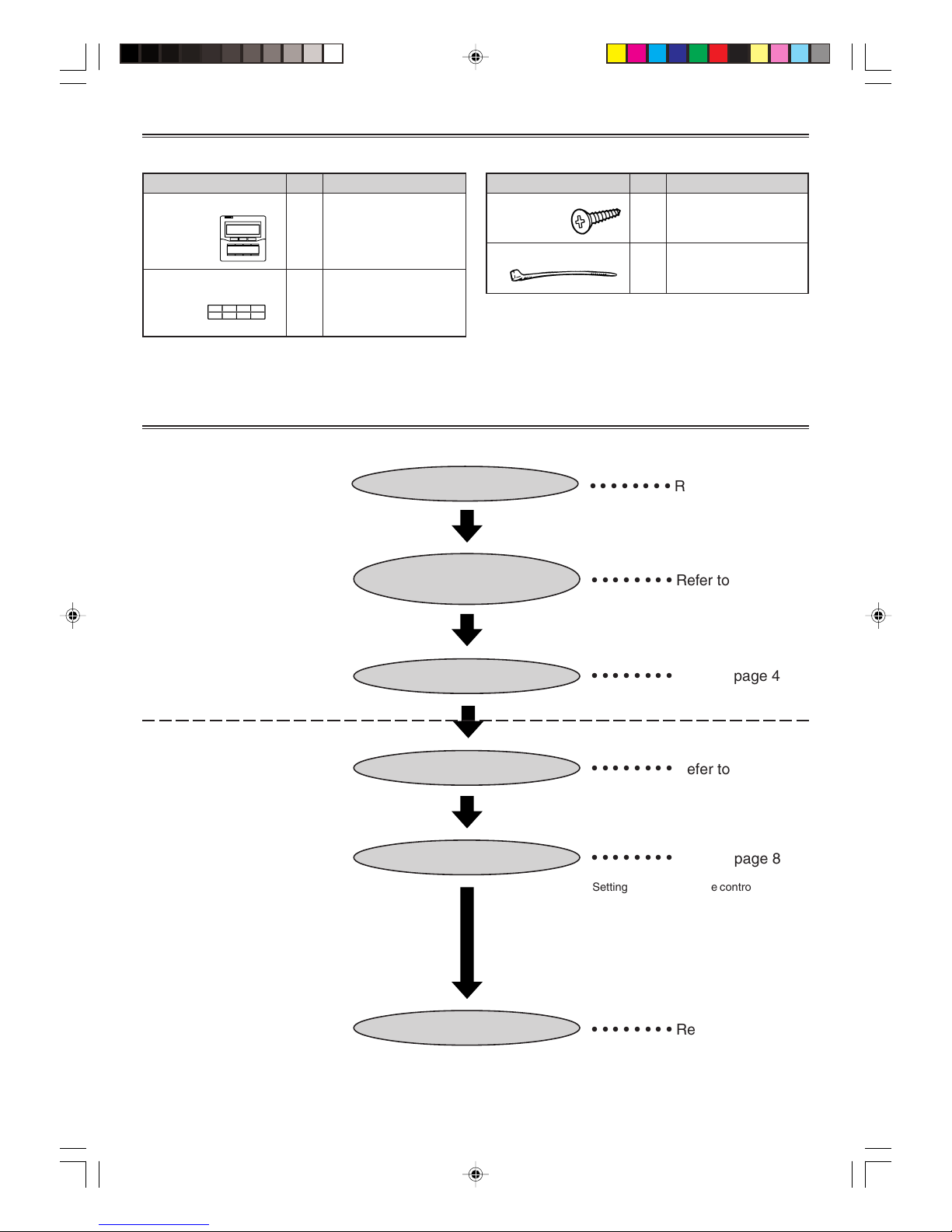
FLOW OF INSTALLATION
The following is the flow of the installation of Group remote controller.
• INSTALLATION
• SETTING
INSTALLING THE REMOTE
CONTROLLER
SETTING THE DIP SWITCH
WIRING
TURN ON THE POWER
REMOTE CONTROLLER SETTINGS
INDOOR UNIT REGISTRATION
○○○○○○○○
Refer to page 4
○○○○○○○○
Refer to page 4
○○○○○○○○
Refer to page 3
○○○○○○○○
Refer to page 7
○○○○○○○○
Refer to page 8
○○○○○○○○
Refer to page 11
• Setting the Group remote controller address
• Time Display Settings
• Timer Operation Settings
• Temperature Range Settings
• Temperature Display Settings
Page 3
En-3
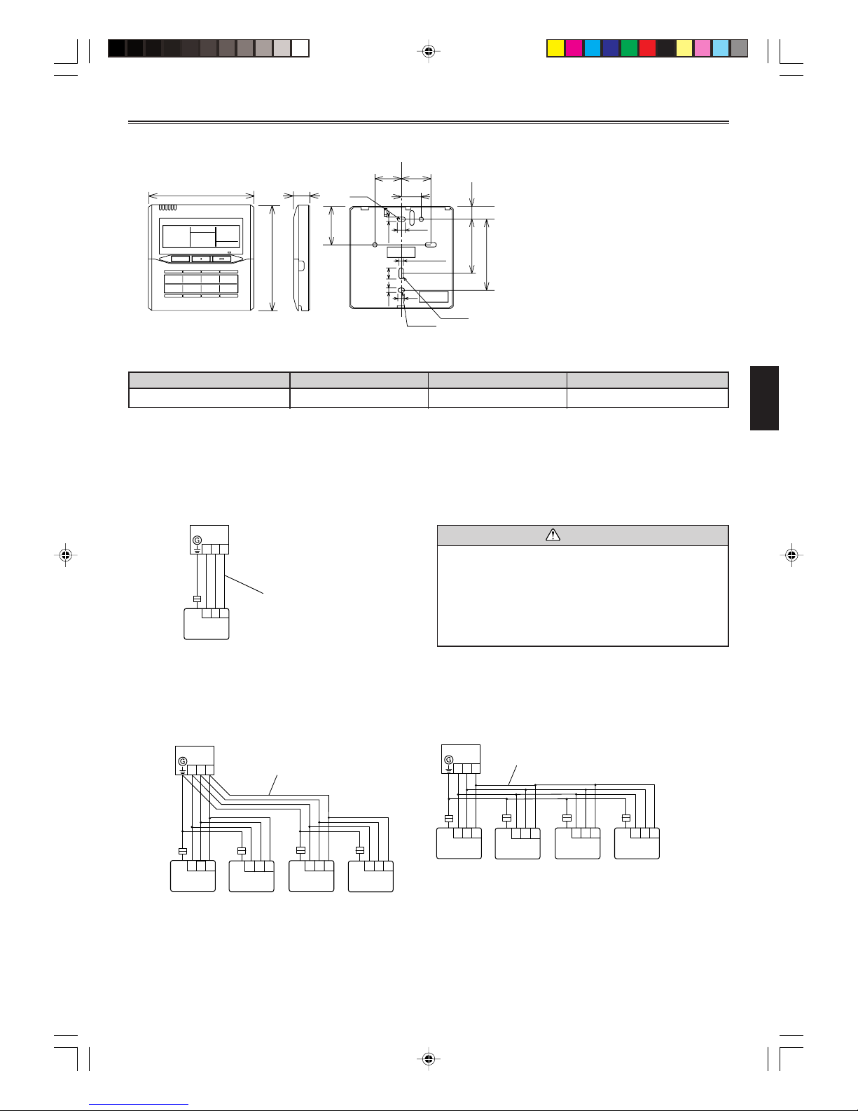
INSTALLATION
1. SPECIFICATION
83.5 (3-9/32)
15.3
(5/8)
63.5 (2-1/2)
Hole
45.3
(1-25/32)
4.5
(3/16)
8
(11/32)
12.5
(1/2)
Hole × 2
Hole × 3
4.5
(3/16)
4.5 (3/16)
6
(1/4)
30
(1-3/16)
33.5
(1-5/16)
23
(29/32)
120 (4-3/4)
120 (4-3/4)
17
(11/16)
When connecting the Group remote controller and Convertor, use the following wiring.
Use
Remote controller cord
Size
0.33 mm
2
(AWG22)
Wire type
Shield cable
Remarks
Polar 3-core
* We recommend that you purchase our service parts for the remote controller cord. Contact service personnel to purchase this.
Unit: mm (in.)
2. WIRING
• Total remote controller cord length: MAX. 100 m (328 ft.)
(1) When connecting one Group remote controller
Remote controller
cord
Convertor
Group remote
controller
CAUTION
• Match the terminal number for the Group remote controller and the number on the terminal for the Convertor
when the connection is made.
(See Fig. 2 for the location of the Group remote controller terminal number.)
• Do not route the remote controller cord near a source
of electromagnetic interference.
(2) When multiple Group remote controllers are connected (multiple Group remote controllers cannot be connected with the J-series.*)
• A maximum of four Group remote controllers can be connected with one Convertor.
• Use of a terminal box is recommended when a junction is made in the wiring.
Convertor
Remote
controller cord
Group remote controller
Convertor
Remote
controller cord
Group remote controller
* It is a J-series model when the model name of the indoor unit ends in “R.”
1
12233
123
123
123
123 123
123
123
123
123 123
Page 4
En-4
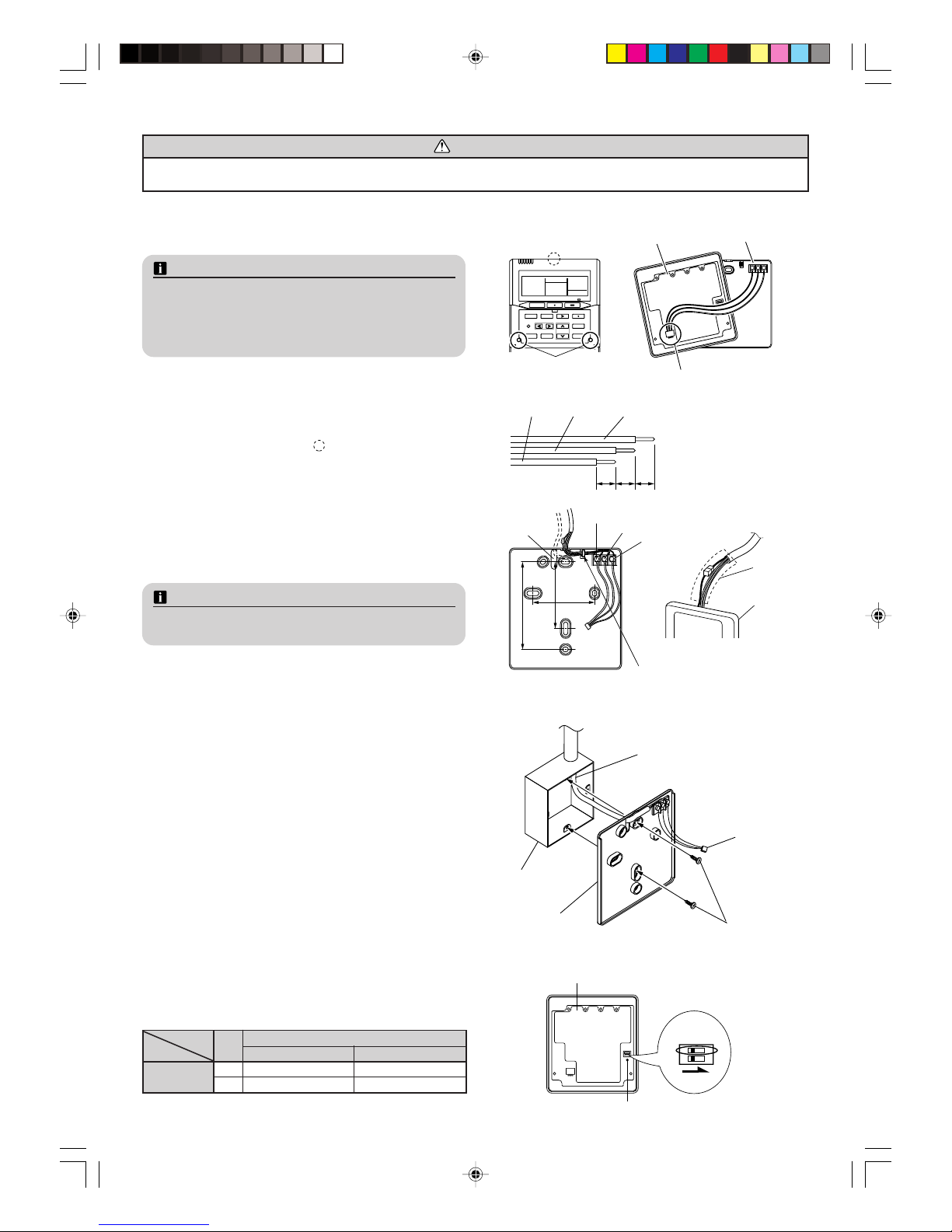
Open the operation panel on the front of the remote controller,
remove the two screws indicated in the right figure and then, remove the front case of the remote controller.
NOTES
When installing the remote controller, remove the connector
from the front case. The wires may break if the connector is
not removed and the front case hangs down.
When installing the front case, connect the connector to the
front case.
● When remote controller cord exposed
1) Make two horizontal or two vertical holes in the mounting
surface (wall, etc.) to install the remote controller. (Fig. 2)
2) Use a tool to cut away the thin area on the upper center of
the front case (indicated by
in Fig. 1).
3) Connect the remote controller cord to the remote controller
terminal board specified in Fig. 2.
4) Wrap the connector and remote controller cords with vinyl
tape or some other type of insulation as shown in Fig. 2.
5) Clamp the remote controller cord with the binder as shown
in Fig. 2.
6) Cut off the excess binder.
7) Install the rear case to the wall, etc., with two screws (ø4 × 16).
(Fig. 3)
NOTES
Step 4) will be noticed by customers, so do it with particular
care.
3. INSTALLING THE REMOTE CONTROLLER
CAUTION
• Do not touch the group remote controller Circuit board and Circuit board parts directly with your hands.
• When working with the wiring, be careful not to scratch or damage the wires.
Fig. 1
Front case (back side)
Rear case
Connector
Screws
63.5 (2-1/2)
63.5 (2-1/2)
83.5 (3-9/32)
Fig. 2
1.12V (Red)
2.Signal (White)
3.COM (Black)
Binder
Hole
Group remote
controller
Insulation
● When remote controller cord embedded
1) Embed the remote controller cord and box.
2) Pass the remote controller cord through the hole in the rear
case and connect the remote controller cord to the remote
controller terminal board specified in Fig. 2.
3) Wrap the connector and remote controller cords with vinyl
tape or some other type of insulation as shown in Fig. 2.
4) Clamp the remote controller cord sheath with the binder as
shown in Fig. 2.
5) Cut off the excess binder.
6) Install the rear case to the wall, box, etc., with two screws
(ø4 × 16).
Fix the two screws in either horizontal or vertical position.
(Fig. 3)
Fig. 3 [Example]
Remote controller cord
Rear case
Box
Screws
Connector
4. SETTING THE DIP SWITCH
Set DIP switch 1 to ON to enable the memory backup.
• Memory backup setting
If there is a power failure when the memory backup is enabled,
the settings stored in the memory will be saved.
ON
ON
OFF
1
2
DIP Switch
Front case (back side)
NO.
SW state
OFF ON
1 ★ Invalidity Validity
2 ★ Fixed at OFF
DIP-Switch
(★ Factory setting)
7
(9/32) (9/32) (9/32)
77
1.12V
(Red)
2.Signal
(White)
3.COM
(Black)
Page 5
En-5
SETTING
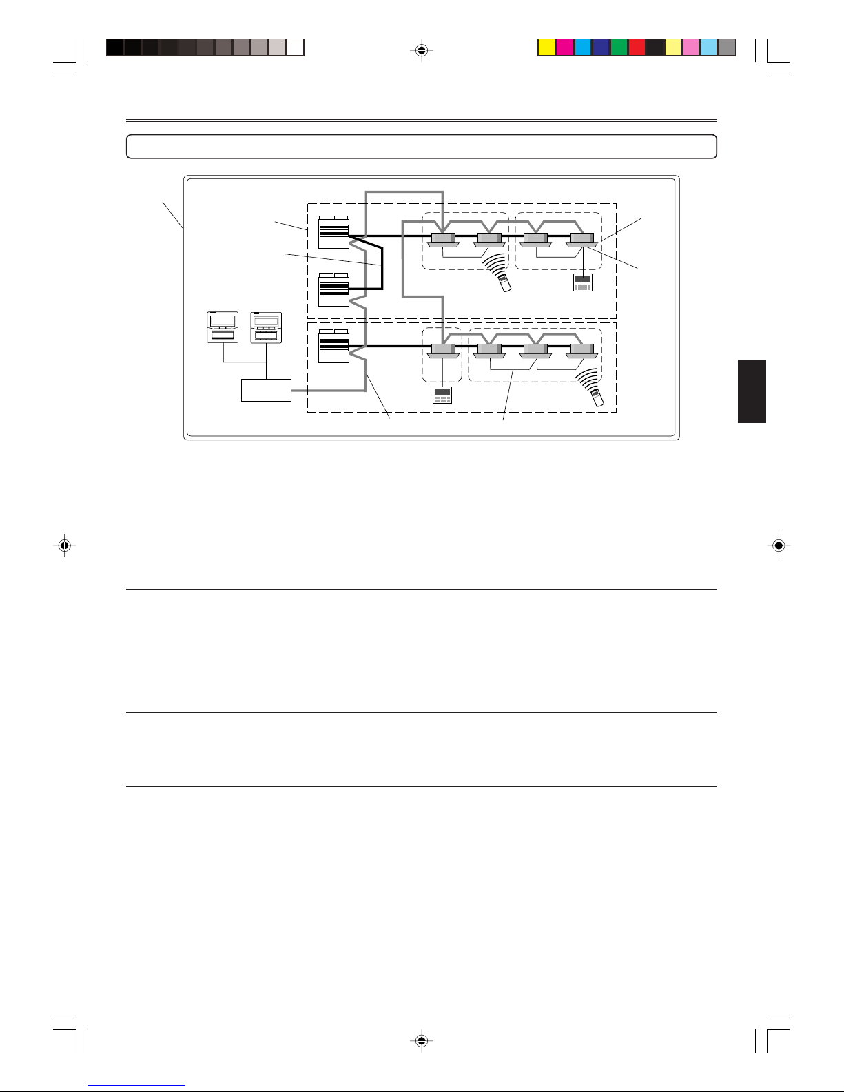
EXPLANATION OF TERMS
Indoor unit
System
Refrigerant system
Refrigerant pipe
Convertor
Outdoor
unit
Group remote controller
Transmission line Controller line
Wireless remote
controller
Wired remote
controller
Remote
controller
group
Controller related items
● System:
This is all of the indoor units, outdoor units and controller units connected by the same transmission line.
● Refrigerant system: [Not for J-series*]
This is a system composed of indoor and outdoor units connected by the same refrigerant pipe.
● Remote Controller group: [Not for J-series*]
This is the smallest unit controlled by group remote controller.
This is a group of indoor units that have been connected with one controller line.
Indoor / Outdoor unit setting (on the Circuit board)
● Refrigerant circuit address (0~99): [Not used for J-series*]
This is the ID individually assigned to each refrigerant system and is used for control.
● Indoor unit address (0~63): [J-series* uses 0-7]
This is the ID individually assigned to each indoor unit and is used for control.
● Remote controller address (0~15): [Not used for J-series*]
This is the ID individually assigned to the indoor units forming each remote controller group and is used for control.
Group remote controller setting
● Group remote controller address (0~3): [J-series* uses “0” only]
This is the ID individually assigned to each group remote controller and is used for control.
* It is a J-series model when the model name of the indoor unit ends in “R.”
Page 6

En-6
● With cover closed
Indoor Unit Name Labels
● With cover open
Setting Display
Day Display
Timer and Clock Display
Timer Mode Display
Timer Mode
(DELETE) Button
DAY Button
Set Time Button
PROGRAM (CLOCK
ADJUST) Button
ENTER Button
Transmission Display
Operation Lock Display
ON/OFF Display
Fan Speed Display
Temperature Display
Operation Mode Display
Start/Stop Button
Select Button
Fan Control Button
Master Control Button
Set Temperature Button
Timer and Clock
Display and setting
Displaying the Status
and Controlling
indoor units
NAME OF PARTS
Indoor Unit Operation
Indicators
Operation Lamp
ALL OFF Button
ALL ON Button
ALL TIMER Button
ON/OFF Button
Page 7

En-7
TURN ON THE POWER
Turn on the power
Once the installation and wiring has been completed, use the following procedure to turn on the power.
1. Turn on the power for all connected indoor units.
2. Turn on the power for all connected outdoor units.
3. Turn on the power for all connected convertor of group remote controllers.
For J-series
1. Turn on the power for all connected indoor units and outdoor units.
2. Turn on the power for all connected convertor of group remote controllers.
Wait for one minute or more after turning on the power before performing the next section.
SETTINGS
Switching to the Settings Screen
Initial Screen
Flashing
Flashing
1
Settings
Hold down the Set Time buttons and simultaneously for two seconds or more to start the Settings.
2
Press the Set Temperature button to select the item to be set.
Settings
: REMOTE CONTROLLER SETTINGS → Page 8
: INDOOR UNIT REGISTRATION → Page 11
, , , , , : Forbidden 1-6
● To complete Settings
Hold down the Set Time buttons and
simultaneously for two seconds or
more to complete the settings.
NOTES
When there is a display other than the initial screen, it is possible that an error has occurred.
Please consult authorized service personnel in such cases.
(
)
Turn on the power
Error code
(Refer to page 14.)
Page 8

En-8
REMOTE CONTROLLER SETTINGS
Remote Controller Settings
Initial Screen
Remote Controller Settings
● To select the setting
DAY
Press the DAY button to select the
item to be set.
Settings : Setting the Group remote controller address → Page 8
, : Forbidden → Page 9
: Time Display Settings → Page 9
: Timer Operation Settings → Page 9
: Temperature Range Settings → Page 10
: Temperature Display Settings → Page 10
Setting the Group remote controller address
To set the Group remote controller address
1
Reverse Advance
Check that it is .
Group remote controller address
Press the Set Time buttons to set the Group remote
controller address.
* For each convertor, make the settings in order
starting with “0” according to the number of Group
remote controllers connected.
* Set to “0” for the J-series.
2
Press the ENTER button.
Check that
and flash for
two seconds.
3
DAY
Press the DAY button to move to
“
Forbidden.”
Page 9

En-9
, Forbidden
To move to the following settings
● Forbidden
Press the DAY button to move to “ Time Display
Settings. ”
● Forbidden
Press the DAY button to move to “ Setting the
Group remote controller address. ”
Time Display Settings (This switches the time display.)
To switch the time display
1
Decrement Increment
Press the Set Time buttons to
set the time display.
Check that it is
.
Time Display Setting
or : 24 Hour Clock Display
: 12 Hour Clock Display 1
: 12 Hour Clock Display 2
2
Press the ENTER button.
Check that
and flash for two
seconds.
3
Press the DAY button to move to “
Timer Operation Settings. ”
Timer Operation Settings (This enables/disables the weekly timer.)
To enable/disable timer operation
Press the Set Time buttons to
set the timer operation setting.
Check that it is
.
Timer operation setting
2
Press the ENTER button.
Check that
and flash for
two seconds.
3
Press the DAY button to move to “
Temperature Range Settings.”
1
Decrement Increment
Enabled Disabled
DAY
DAY
DAY
Page 10

En-10
Temperature Range Settings (This changes the temperature range.)
To set the temperature range
Press the Set Time buttons to
set the temperature range.
Check that it is
.
Temperature range setting
2
Press the ENTER button.
Check that
and flash for two
seconds.
3
Press the DAY button to move to “
Temperature Display Settings.”
1
Decrement Increment
● The temperature range set for heating operation is different.
DAY
Temperature Display Settings (This switches the display between Celsius and Fahrenheit.)
To switch the temperature display
Press the Set Time buttons to
set the temperature display.
Check that it is
.
Temperature display setting
2
Press the ENTER button.
Check that
and flash for two
seconds.
3
Press the DAY button twice to move
to “
Setting the Group remote con-
troller address.”
Celsius Fahrenheit
1
Decrement Increment
DAY
Moving to “ Indoor Unit Registration”
To move to indoor unit registration
Pressing once moves to indoor unit
registration
Pressing seven times moves to indoor
unit registration
Press the Set Temperature button
once or press the Set Tem-
perature button
seven times to move to indoor unit registra-
tion.
: 10 °C – 30 °C (48 °F – 88 °F)
: 16 °C – 30 °C (60 °F – 88 °F)
Page 11

En-11
INDOOR UNIT REGISTRATION
● A maximum of 8 remote controller groups can be registered for a Group remote controller.
● Remote controller groups in 2 different refrigerant systems that are connected to a single convertor can be registered.
● The remote controller groups registered can be monitored and controlled.
● When registering indoor units to each of the buttons, consult the customer.
Indoor unit registration screen
1
2
3
4
Refrigerant circuit address
(Not shown with J-series)
Registration position
Indoor unit address
Remote controller address
(Not shown with J-series)
Indoor Unit Registration Methods
● Manual registration
● Automatic registration (J-series only)
Manual Registration
To register indoor units manually
1
● Registration position selection
Press the Select button to select the position for registering the indoor unit
2
● Refrigerant circuit address selection (Not used for J-series)
Press the DAY button to select the refrigerant circuit address for the indoor unit being registered.
• Hold down a Set Time button to scroll through the addresses quickly.
DAY
3
● Indoor unit address selection
Press the Set Time buttons to select the indoor unit address for the indoor unit being registered.
• Hold down a Set Time button to scroll through the addresses quickly.
Decrement Increment
For J-series
When a remote controller group made up of a single indoor unit is registered, select the indoor unit address.
Initial Screen
See EXPLANATION OF TERMS on page 5 for
explanations of each address.
Page 12

En-12
4
When a remote controller group made up of multiple indoor units is registered, the remote controller address and the
indoor unit address are selected.
Decrement Increment
● Remote controller address selection
Indoor unit address
ex.: Refrigerant circuit address “
”, remote control-
ler address “
”
* The refrigerant circuit address is the same as
the address for the indoor unit set first (remote
controller address “
”) and cannot be changed.
1. Press the PROGRAM (CLOCK ADJUST) button to select the remote controller address of the indoor unit being registered.
2. Press the Set Time buttons to select the indoor unit address of the indoor units in the same remote controller group that is being
registered.
3. Repeat steps 1 and 2 to register all the indoor units in this remote controller group.
5
Press the ENTER button to register the selected indoor unit. Check that the refrigerant
circuit address, indoor unit address,
, and flash (up to two minutes).
• Press the Timer Mode (DELETE) button during this time to cancel the registration.
6
Repeat steps from 1 to 5 to register
other indoor units.
● To delete the registered settings
1. Press the Timer Mode (DELETE) button during steps 2 to 4 to reset the contents of
the registration. (If the currently displayed indoor unit is part of a remote controller
group with multiple units, only the settings for this indoor unit are reset.)
2. Press the ENTER button to delete the contents of the registration.
Automatic registration (J-series only)
To register indoor units automatically
CLOCK ADJUST
Press the PROGRAM (CLOCK ADJUST) button to start automatic registration. Automatic registration completes in approximately
two minutes.
NOTES
(1) Be careful not to end the settings or switch the indoor unit before pressing the ENTER button. Otherwise, the changed settings
will be lost.
(2) If
is displayed during the registration of an indoor unit, the Group remote controller address, refrigerant circuit address,
or indoor unit address may incorrect. Check again.
Remote controller address
Refrigerant circuit address
● Indoor unit address selection
Flashing
Page 13

En-13
Moving to “ REMOTE CONTROLLER SETTINGS”
To set the remote controller
Press the Set Temperature button seven times or press the
Set Temperature button
once to move to remote controller
settings.
Completing All of the Settings
To complete Settings
● When the remote controller settings and indoor unit settings are complete
Hold down again the Set Time buttons and simultaneously for two seconds or more
to complete Settings.
FINAL STEP
To apply the label
Write the name of the indoor unit or the room where it is installed on the label, and apply it to the Group remote controller.
• Consult the customer about the names to be written on the label.
• Explain to the customer about the indoor units that have been registered to each button.
Label (Standard parts)
84 × 21 (3-9/32 × 13/16)
Pressing seven times moves
to remote controller settings
Pressing once moves to remote
controller settings
Page 14

En-14
00 No error No error No error
01 –– –
02 Model information abnormal Model information abnormal –
03 Microcomputer communication error Microcomputer communication error Microcomputer communication error
04 Power supply frequency abnormal Power supply frequency abnormal –
05 –– Parallel communication error
06 EEPROM access error EEPROM access error EEPROM access error
07 EEPROM deletion error EEPROM deletion error –
08 –– –
09 Compressor 1 error Room temperature thermistor error –
0A Compressor 2 error Heat exchanger thermistor (middle) error –
0b Compressor 3 error Heat exchanger thermistor (inlet) error –
0C – Heat exchanger thermistor (outlet) error –
0d Discharge temperature thermistor 1 error Blower temperature thermistor error –
0E Discharge temperature thermistor 2 error ––
0F Discharge temperature thermistor 3 error ––
10 Outdoor temperature thermistor error ––
11 Heat exchanger inlet thermistor 1 error Drain abnormal –
12 Heat exchanger inlet thermistor 2 error Room temperature abnormal –
13 Heat exchanger inlet thermistor 3 error Indoor unit fan error –
14 Heat exchanger outlet thermistor 1 error ––
15 Heat exchanger outlet thermistor 2 error ––
16 Heat exchanger outlet thermistor 3 error ––
17 Suction temperature thermistor error ––
18 –
Standard wired remote control communication error
–
19 Discharge pressure sensor error ––
1A Liquid pressure sensor error – Address setting error
1b Suction pressure sensor error ––
1C Oil sensor error – Connection error
1d –– System error
1E –– –
1F Transmission error Transmission error Transmission error
20 –– –
21 Discharge temperature 1 error ––
22 Discharge temperature 2 error ––
23 Discharge temperature 3 error ––
24 High-pressure error ––
25 Low-pressure error ––
26 –– –
27 Oil recovery error ––
28 Pump down error ––
ERROR CODE
The air conditioning system must be inspected if “E✽:✽✽” (error code) appears on the Timer and Clock Display, or the operation lamp
is flashing.
The following explains the meaning of each of the error codes.
Model code
Error code
Model code
: Outdoor unit
: Indoor unit
: Group remote controller
: Convertor
Group remote controller error
Convertor error
Outdoor unit error
Indoor unit error
Error
Code
 Loading...