

Page 1
SETTING MANUAL
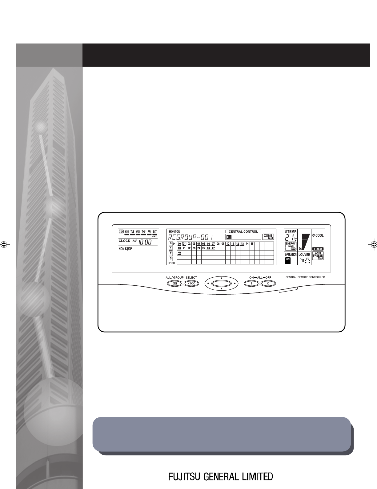
CENTRAL REMOTE CONTROLLER
UTB-YCA
UTB-GCA
Before using this controller, please read this [SETTING MANUAL]
to ensure correct operation. Keep this manual for future reference.
Page 2

Page 3

CONTENTS
1. SAFETY PRECAUTIONS.............................................................. 2
2. SYSTEM OUTLINE ....................................................................... 3
2-1. SYSTEM OUTLINE............................................................................. 3
2-2. EXPLANATION OF TERMS ................................................................ 5
2-3. NAMES AND FUNCTIONS OF THE PARTS ...................................... 8
2-4. PRECAUTIONS WHEN SETTING THE SYSTEM ............................ 10
2-4-1. Priority of remote controller setting ......................................................... 10
2-4-2. Group information store .......................................................................... 10
3. SETTING ..................................................................................... 11
3-1. FLOW OF INSTALLATION ................................................................ 11
3-2. SETTING OPERATION..................................................................... 13
3-2-1. Turn on power ......................................................................................... 13
3-2-2. Initial setting ............................................................................................ 13
3-2-3. Clock setting ........................................................................................... 24
3-2-4. Group information store .......................................................................... 26
3-2-5. Test operation ......................................................................................... 28
4. ERROR DISPLAY........................................................................ 30
4-1. ERROR MONITOR ........................................................................... 30
4-2. ERROR CODES ............................................................................... 32
4-3. ALL CLEAR SWITCH........................................................................ 33
5. SPECIFICATIONS ....................................................................... 34
5-1. SPECIFICATIONS............................................................................. 34
5-2. DIMENSIONS ................................................................................... 34
1
Page 4
1. SAFETY
PRECAUTIONS
1. SAFETY PRECAUTIONS
• Before using CENTRAL REMOTE CONTROLLER, read this “SAFETY PRECAUTIONS” thoroughly to ensure the correct operation.
• This section discribes the important safety information to operate CENTRAL REMOTE CONTROLLER.
• The meanings of “WARNING” and “CAUTION” are explained as follows.
This mark indicate procedures which, if improperly performed, are most
WARNING!
likely to result in the death of or serious injury to the user or service personnel.
CAUTION!
This mark indicates procedures, which might result in personal harm to
the user or damage to property if improperly performed.
WARNING!
• Do not attempt to install this controller by yourself.
• This controller contains no user-serviceable parts. Always consult authorized service personnel for repairs.
• When moving this controller, consult authorized service personnel for disconnection and
installation.
• If the problem (burning, smell, etc) occurs, turn off the electrical breaker immediately to
stop operation and then consult the authorized service personnel.
• If the power supply cord becomes damaged, contact your service representative for instruction.
CAUTION!
• Do not expose the controller directly to water.
• Do not operate the controller with wet hands.
• Do not touch the switches with sharp objects.
• Always turn off the electrical breaker whenever cleaning the controller, the air conditioner
or the air filter.
• Ensure that all electronic equipment is at least one meter away from the controller.
• Avoid installing the controller near a fireplace or other heating apparatus.
• When installing the controller, take precautions to prevent access to infants.
• Do not use inflammable gases near the controller.
• At the time of installation, always provide a breaker for electrical leakage.
• Always use fuses with the proper capacity and type.
2
Page 5
2. SYSTEM OUTLINE
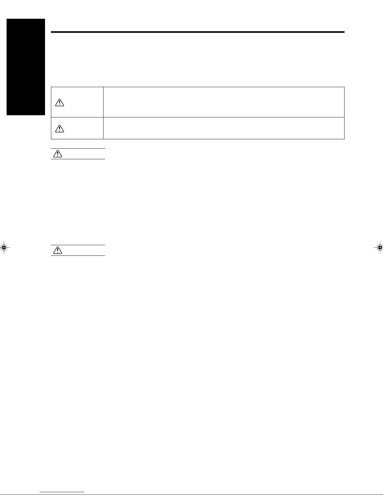
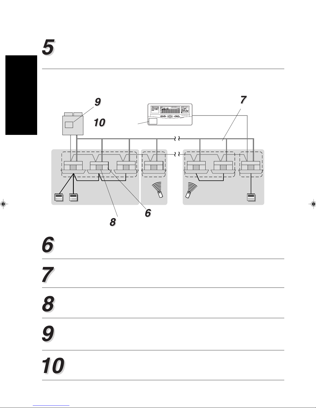
2-1. SYSTEM OUTLINE
Transmission line
Refrigeration
system 1
3 4W 50Hz 380 - 415V
Centr
al remote
controller
Controller line
Group
1 50Hz
220 - 240V
Indoor unit
2. SYSTEM OUTLINE
1 50Hz
220 - 240V
Remote Controller Group
Please consult your sales representative when two or more central remote controllers need to be
installed in one system.
• What is the central remote controller?
The central remote controller allows all the stored remote controller groups (the indoor units) to
be controlled from a remote location.
(Refer to “2-3. EXPLANATION OF TERMS 1” for details about remote controller groups.)
• Three functions of the central remote controller
• CENTRAL CONTROL
The central control provides management of the remote controller groups (the indoor units).
This includes placing restrictions on the standard remote controllers or performing memory operation for easily reproducing operating conditions that have been saved.
• OPERATION CONTROL
The operation control provides a controlled operation (such as the to stop operation) of the stored
remote controller groups (the indoor units) in the same manner as the standard remote controller.
• TIMER CONTROL
The timer control allows the starting and stopping of stored remote controller groups and indoor
units through the timer functions in the central remote controller. These timer functions include:
the off timer, on timer 1, on timer 2 and weekly timer.
3
Page 6

• Three control methods of the central remote controller
• Individual control
2. SYSTEM OUTLINE
Provides control for each respective remote controller group.
• Group control
Provides control for each group which is made up of single or multiple previously set remote
control groups.
(Refer to “2-3. EXPLANATION OF TERMS” for details about groups.)
• All control
Provides control for all remote control groups that haven been stored in the central remote controller.
4
Page 7
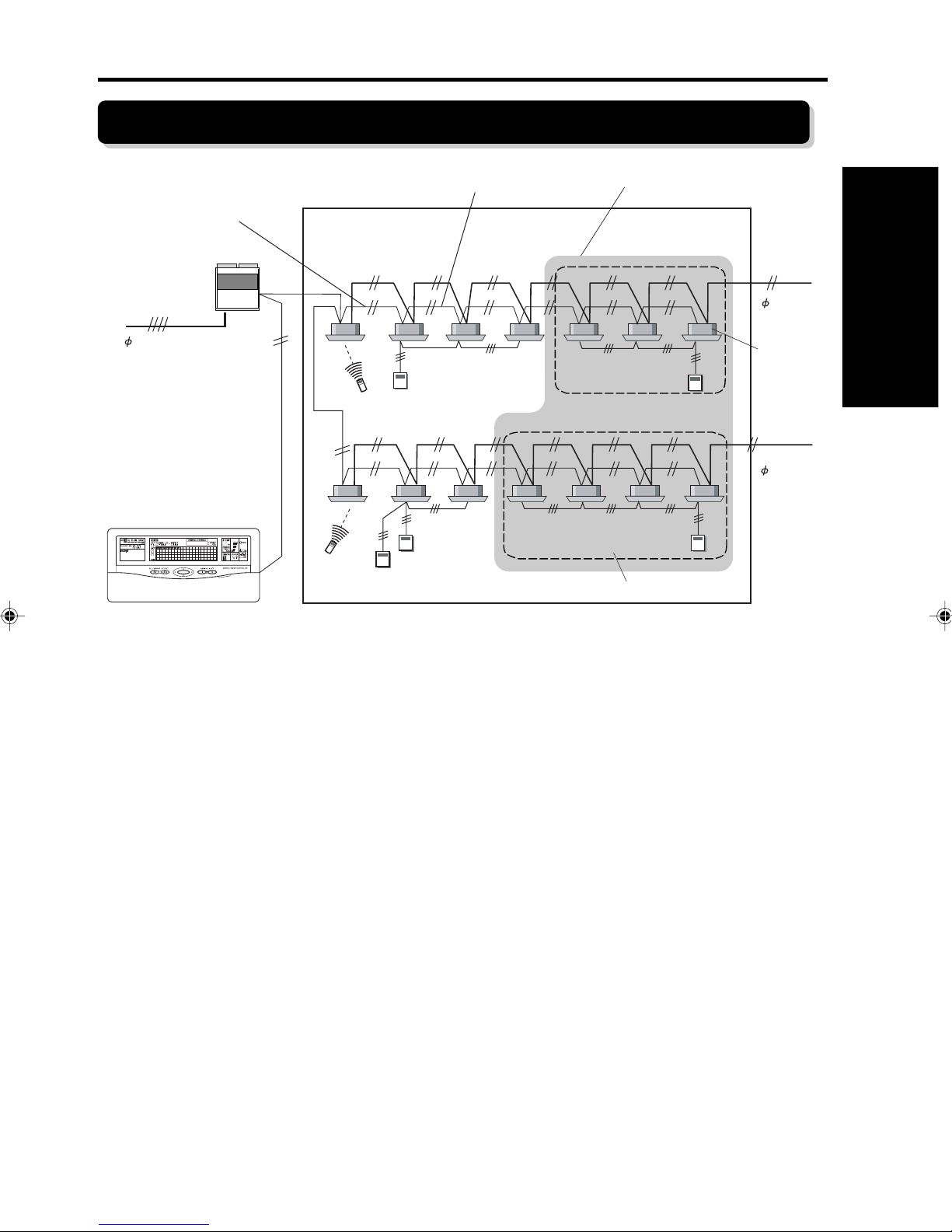
2-2. EXPLANATION OF TERMS
■Controller related items
Transmission line
Outdoor unit
Central remote
controller
Remote controller group Group
Controller line
Indoor
unit
All
Refrigerant
system
System
2. SYSTEM OUTLINE
Wired remote
controller
Wireress remote
controller
Remote Controller group:
This is the control unit of indoor units that have been connected with one controller line
as well as the control unit of a single indoor unit that has not been connected with any
controller line.
These two kinds of control units are the smallest unit controlled by central remote controller, and are called a remote control group.
Group:
This is a control unit comprised single or multiple remote control groups.
All:
This is a control unit of all remote control groups that have been stored in the central
remote controller.
Refrigerant system:
This is a system that is composed of indoor units, outdoor unit as well as those of
relevant control equipment. All of the units and the equipment are connected with pipes
with the same refrigerant.
5
Page 8
System:
This is all of the indoor units, outdoor unit as well as those of relev ant control equipment
2. SYSTEM OUTLINE
(central remote controllers, standard remote controllers) that are connected with the
same communication cable.
■Address related items
Group address
00
Refrigerant system
address
Central remote
controller address
0
01 2
00
00
0
00
01
1
00
02
2
00
03
0
Remote address
Indoor unit address
Remote controller address (0~15):
This is the ID individually assigned to the indoor units forming each remote control
group and is used for control.
00
13
0
00
14
1
00
15
0
Group number (0~63):
This is the ID individually assigned to each group and is used for control.
Indoor unit address (0~15):
This is the ID individually assigned to each indoor unit and is used for control.
Refrigerant system address (0~99):
This is the ID individually assigned to each refrigerant system and is used for control.
Central remote controller address (0~15):
This is the ID individually assigned to each central remote controller and is used for
control.
6
Page 9
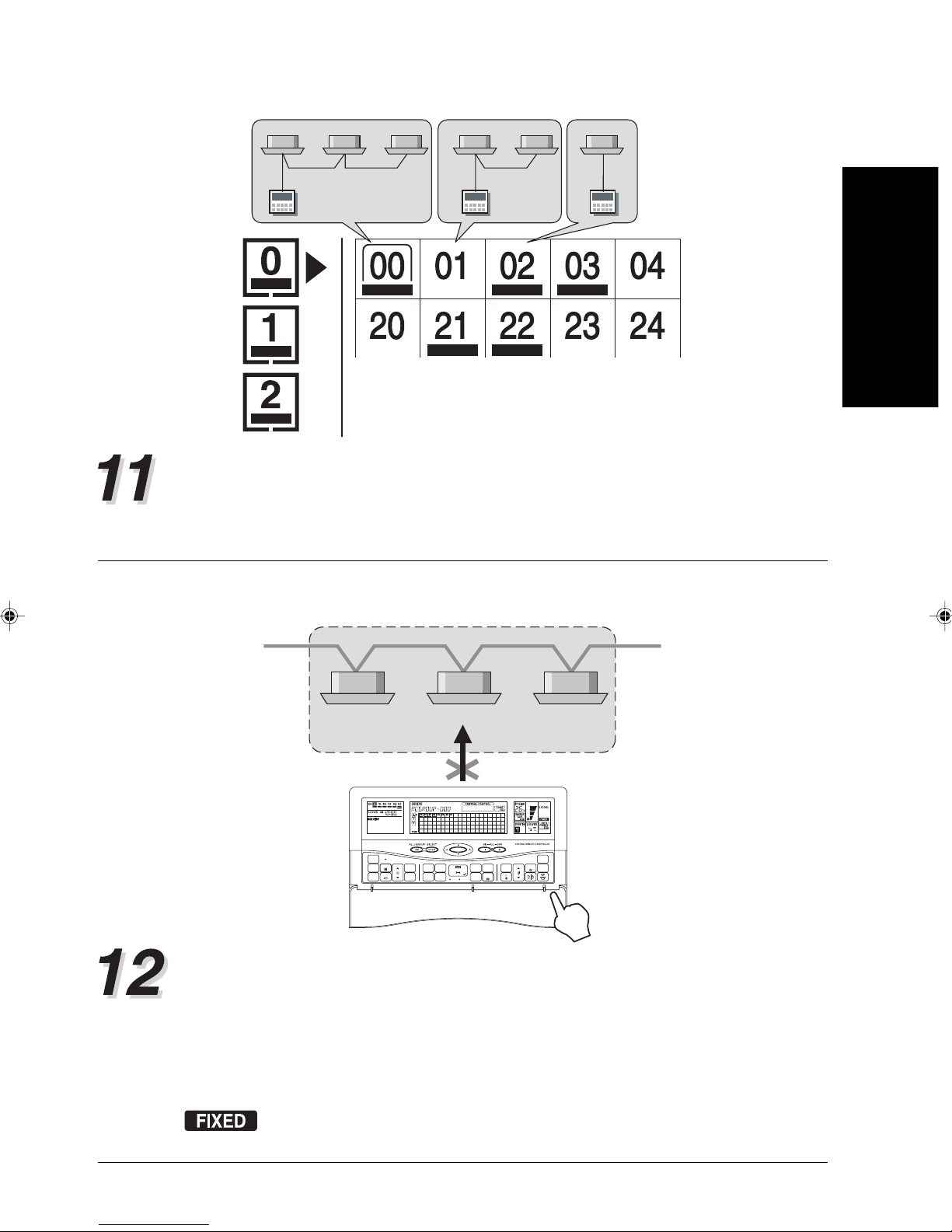
One central control number indicates
one remote control number.
Central control number (0~339):
These are the numbers by which the control of the indoor units is perf ormed.
Each number that appears on the LCD of the central remote controller is the number that
has been assigned individually to a remote control group to be controlled and has been
stored in the central remote controller . Ref er to the SETTING MANU AL f or specific details.
Heating priority setting
2. SYSTEM OUTLINE
HEAT
[FIXED]
CLOCK
ADJUST
TIMER
MODE
TIMER
COPY
Cooling / Heating priority:
ACL
DAY
TIME
DAY OFF
Cooling operation
HEAT
[FIXED]
TIMER
MEMORY
CENTRAL
CONTROL
OPERATION
DELETE
TIMER
MEMORY
GROUP
SETTING SETTING
SET
CHECK
ENERGY ANTI
BACK
ZONE
SET
SAVE
FILTER
ON OFF
RESET
DELETE
TEST
HEAT
[FIXED]
MASTER
CONTROL
FAN
TEMP.
CONTROL
FREEZE
When a HEAT PUMP TYPE oper ating system is used, the system can only be performed
in one of two operation modes (cooling / heating) for single refrigerant system. When an
indoor unit in the system first starts an heating operation, the system is then in “heating
priority”. This means the system will refuse a command for changing the operation mode.
On the other hand, when an indoor unit in the system first starts a cooling operation, the
system is then in “cooling priority”. The system will refuse to change to any other operation
mode, except f or the drying operation.
will appear on the LCD when the indoor units associated with the selected
central control number exists in cooling / heat pump type refrigerant system.
7
Page 10
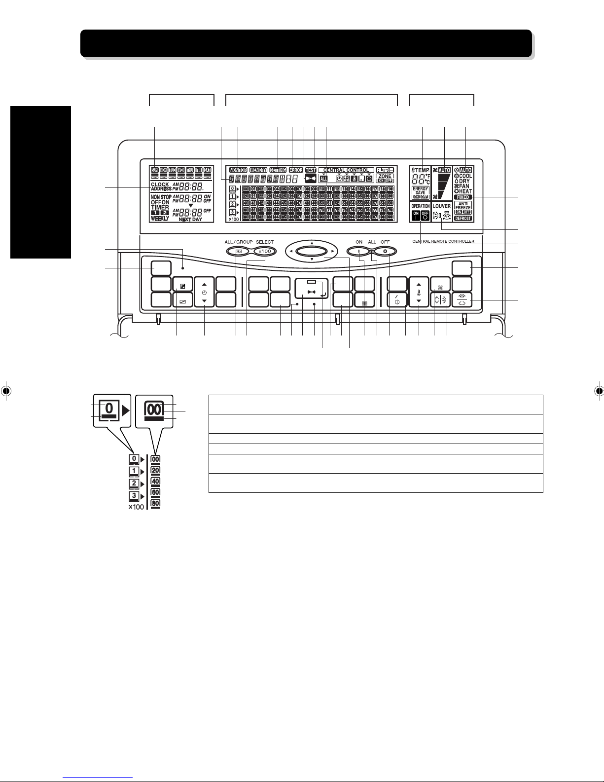
2-3. NAMES AND FUNCTIONS OF THE PARTS
2. SYSTEM OUTLINE
2
3
4
TIMER CONTROL
AREA
ACL
CLOCK
ADJUST
DAY
TIMER
MODE
TIMER
DAY OFF
COPY
OPERATION
CENTRAL CONTROL AREA
781 9 0 BC Q R S
TIMER
DELETE
TIMER
SET
MEMORY
OPERATION
MEMORY
SETTING
CENTRAL
CONTROL
GROUP
SETTING
A
CHECK
SET
TEST
BACK
DELETE
ZONE
FILTER
RESET
DELIHF65 G K Y
CONTROL AREA
TEMP.TIME
ENERGY
SAVE
ON OFF
XWPON
FAN
CONTROL
Z
MASTER
CONTROL
ANTI
FREEZE
MJ
T
U
V
[
\
c
d
b
]
a
CENTRAL CONTROL NUMBER
] Visible numbers represent the central control numbers that have been stored. An error will
^
cause the relevant central control number to flash.
^ Cursor: To be used in order to select the central control number. It flashes when the filter need
to be cleaned or exchanged.
a Visible under lines distinguish the operating indoor units from all indoor units.
b Page cursor: To show the current page.
c Visible page numbers inform that there are some central control numbers in the page. An error
will cause the relevant page number to flash.
d Visible under lines inform that at least one indoor unit which is stored in this page is now
operating.
8
Page 11
TIMER CONTROL AREA
1 DAY OF THE WEEK DISPLAY
2 CLOCK AND ADDRESS DISPLAY
3 ALL CLEAR BUTTON
4 CLOCK ADJUST BUTTON
5 DAY BUTTON
6 TIME BUTTON
Displays the day of the week.
Shows the current time and address.
To delete all set value in the central remote controller.
To set the time.
To change the day.
To set ON/OFF time.
CENTRAL CONTROL AREA
7 STATUS DISPLAY
8 MONITOR DISPLAY
9 SETTING DISPLAY
0 ERROR DISPLAY
A TRANSMIT INDICATOR DISPLAY
B TEST DISPLAY
C GROUP CONTROL DISPLAY
D ALL / GROUP BUTTON
E SELECT
F GROUP SETTING BUTTON
G CHECK BUTTON
H SET BUTTON
I TEST BUTTON
J SET LED
K BACK BUTTON
L DELETE BUTTON
M SELECT BUTTON
N ALL ON BUTTON
O ALL OFF BUTTON
P ALL ON / OFF LED
××
×100 BUTTON
××
Displays the various kinds of information.
Comes on together with an individual status display.
Comes on during various setting.
Comes on or flashes when error is detected.
Flashes in the period of sending the new setting from the central remote controller to other
units.
Comes on during test operation.
Displays the stored central control number and the operating status of the currently
selected indoor units.
To change the control mode (individual / group / all).
To switch to the next screen of the central control numbers by 100.
To start the group setting.
To switch to error code display.
To confirm the new setting and to send signals to the indoor units whose settings need to
be changed.
To start test operation.
Lights up when the new setting has been made. It will go out when the newly set
information has been sent to the relevant indoor units.
To cancel the just made setting and to return to the previous screen.
To delete the set item.
To select the central control number in central control display.
To start the operation of all indoor units stored in the central remote controller.
To stop the operation of all indoor units stored in the central remote controller.
Flashes when error occurs. It will light up when an indoor unit is operating.
2. SYSTEM OUTLINE
OPERATION CONTROL AREA
Q TEMPERATURE DISPLAY
R FAN CONTROL DISPLAY
S MASTER CONTROL DISPLAY
T FIXED COOLING OR HEATING
DISPLAY
U AIRFLOW DIRECTION DISPLAY
V ON / OFF DISPLAY
W ON / OFF BUTTON
X TEMP. BUTTON
Y FAN CONTROL BUTTON
Z HORIZONTAL AIRFLOW DIRECTION
AND SWING BUTTON
[ MASTER CONTROL BUTTON
\ VERTICAL AIRFLOW DIRECTION AND
SWING BUTTON
Shows the set temperature.
Shows the set fan speed.
Shows the current operating mode.
Comes on when the indoor unit is set in the cooling and heat pump type refrigerant system.
Shows the method to control the airflow direction.
Shows the operating condition (ON / OFF) of the indoor units associated with the selected
central control number.
To turn the selected indoor units on and off.
To set room temperature.
To change the fan speed.
To set the angle or movement of up / down swing of the flaps.
To change the operating mode.
To set the angle or movement of right / left swing of the flaps.
9
Page 12
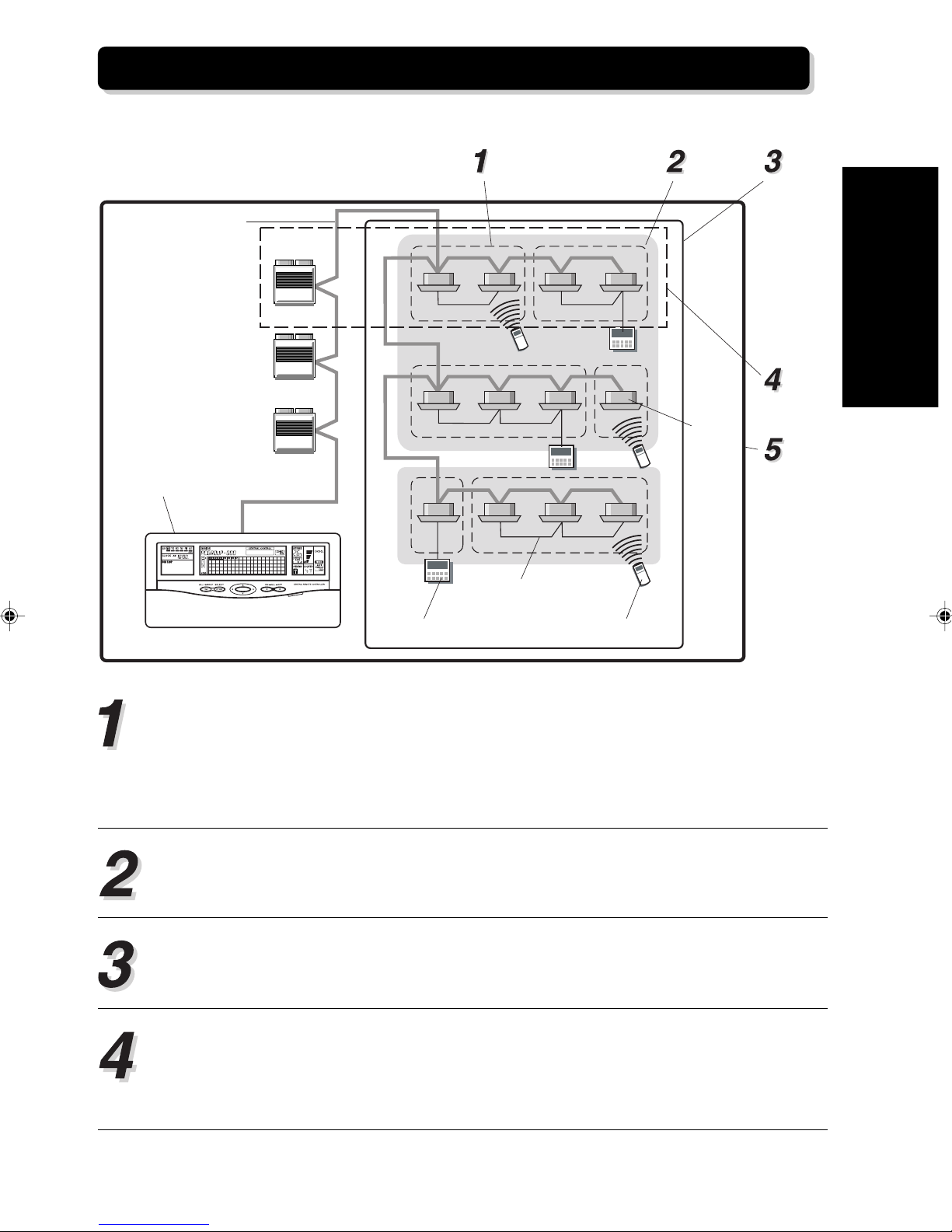
2-4. PRECAUTIONS WHEN SETTING THE SYSTEM
2-4-1. Priority of remote controller setting
2. SYSTEM OUTLINE
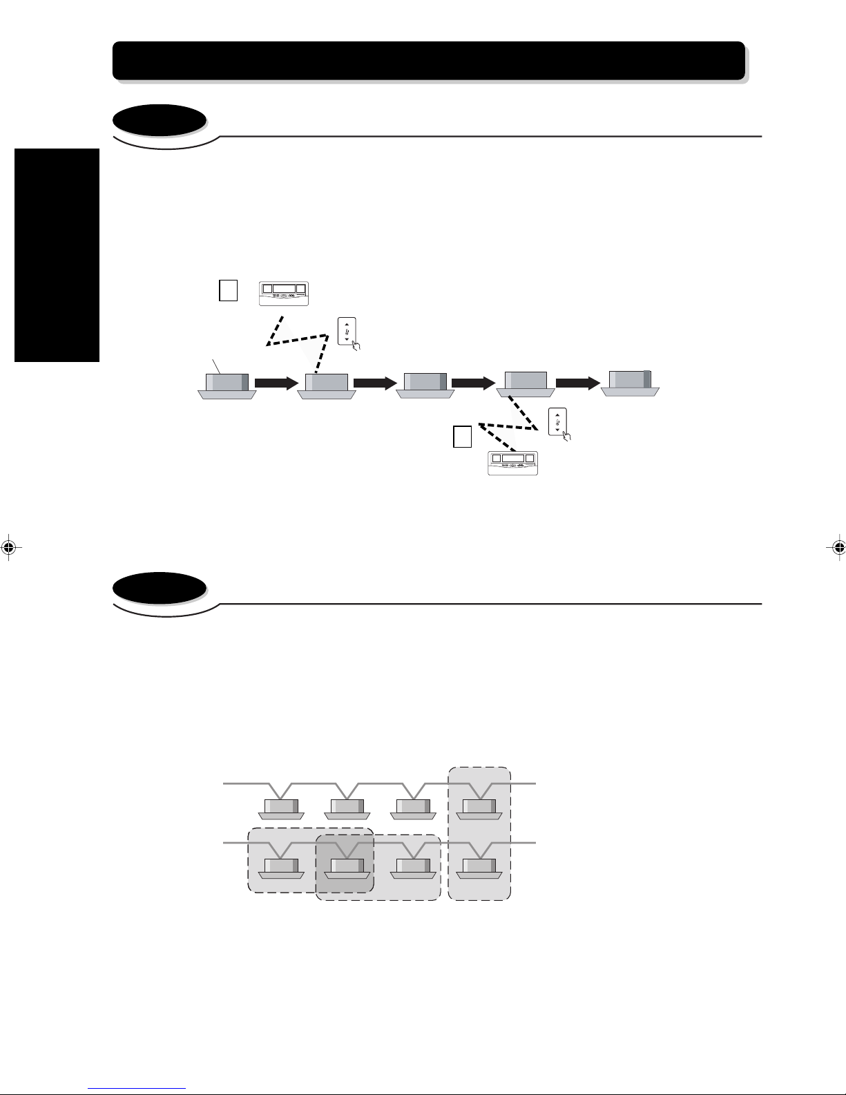
The most recent control transmission has priority. In other words, if two controllers (standard remote controller, central remote controller) send different control command to one indoor unit, it is
the last transmission that will have priority and be used by the indoor unit.
(Example) If the indoor unit is operating at a setting of 25 °C using a command from central remote
controller 1 and receives a command to operate at a setting of 20 °C from central remote controller
2, the indoor unit will operate at the setting of 20 °C.
1
Central remote controller 1
TEMP.
Indoor unit
OFF
OFF
Setting of 25°C
Operating at 25°C
25°C
2
Central remote controller 2
Operating at 20°C
TEMP.
Setting of 20°C
20°C
This applies when performing separate operations from different controllers.
Central remote controller ⇔ Standard wired remote controller or Central remote controller 1 ⇔
Central remote controller 2.
2-4-2. Group information store
The following show the restrictions on group information store.
• A maximum of 64 groups can be formed in one system.
• A maximum of 64 remote control groups can be stored per group.
• Since the remote control group is the smallest control unit and can not be broken up, the
group must be made up with complete remote control groups.
The following show examples of group formation. There are some restrictions on operating
mode, on display for the following occasions.
• Group formed with the indoor units in two refrigerant systems.
When part of indoor units exist in cooling & heat pump type refrigerant system, certain operating
mode of the group can not be carried out even if the operating mode is shown on the LCD. In
addition, the operating mode is limited owing to cooling / heating priority setting.
• Overlapping groups.
The operating condition of the indoor units overlapped in the group is determined by the control
signal last sent to indoor units.
10
Refrigerant system 1
Refrigerant system 2
Page 13

3. SETTING
3-1. FLOW OF INSTALLATION
The following is the flow of the installation of a central remote controller.
• INSTALLATION
INSTRUCTION SHEET
• SETTING MANUAL
DIP-SW setting • • • • Refer to “INSTALLATION
INSTRUCTION SHEET”.
Installation / Wiring • • • • Refer to“INSTALLATION
INSTRUCTION SHEET”.
Turn on power • • • • Refer to “3-2-1 Turn on
power”.
Initial setting • • • • Refer to “3-2-2 Initial
setting”.
Clock setting • • • • Refer to “3-2-3 Clock
setting”.
Group information store • • • • Refer to “3-2-4 Group
information store”.
3. BASIC OPERATION
Test operation • • • • Refer to “3-2-5 Test
operation”.
11
Page 14

3. BASIC OPERATION
Notes Setting control panel DIP SW2
No.
3 ★ Non-display Display For setting filter indicator
4 ★ °C display °F display For setting the unit for the temperature display
DIP SW2
[DIP SW2-3] For setting filter replacement indicator
• This is used to set whether or not the filter indicator will come on when it is time to clean the filter.
[DIP SW2-4] For setting the unit for the temperature display.
• This is used to set the temperature display to displa y either centigrade (°C) or Fahrenheit (°F).
[DIP SW2-5] For validity / invalidity the standard remote controller operation prohibit function.
• This is used for validity / invalidity the standard remote controller operation prohibit function.
[DIP SW2-8] For enabling / disabling the backup function.
• Performs the enabling / disabling of the backup function by the internal battery.
• When it is enabled, the various settings are saved using the internal battery if there is an interruption or stoppage of
the power supply.
• Always enable this function when installing the unit. (Note: It is disabled when shipped from the factory to prevent
consumption of the battery charge.)
• Do not change any other switches.
• Always turn off power breaker before changing the switch settings.
• Refer to “3-2-2. Initial setting” DIP-SW positions.
5 ★ Validity Invalidity For validity / invalidity the standard remote
8 ★ Disabled Enabled For enabling / disabling the backup function
Sw state
OFF ON
Details
controller operation prohibit function
(★ : Factory setting)
12
Page 15

Turn on power Initial setting Clock setting
Group information store
Test operation
3-2. SETTING OPERATION
3-2-1. Turn on power
Once the installation and wiring has been completed, use the following procedure to turn on the
power.
1. Turn on the power for all connected indoor units.
2. Turn on the power for all connected outdoor units.
3. Turn on the power for all connected central remote controllers.
Wait f or one min ute or more after turning on the power bef ore perf orming the initialization shown in
“3-2-2. Initial setting”.
3-2-2. Initial setting
The initial settings are performed by the initial setting mode. This is the required setting mode when
performing operation using the central remote controller. Initial setting mode is started under the
following conditions .
• When the power for the central remote controller is turned on for the first time.
• When SW42 on the control circuit board is pressed.
3. BASIC OPERATION
DIP-SW. 2
SW. 42
How to remove the case top of the control
panel.
• Inser t a flap-tip screw driver and turning
it to remove the cover.
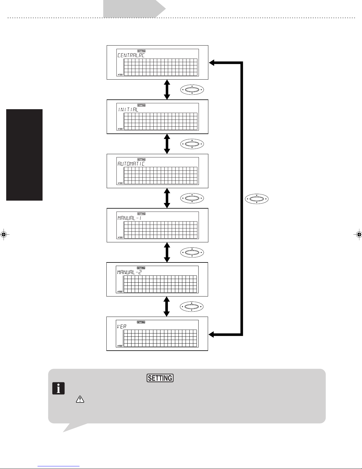
When the power is turned on for the central remote controller for the first time, initial setting mode
automatically starts so that the initial settings for the central remote controller can be performed.
These settings are performed using the following procedure.
1. Central remote controller address settings.
2. System information scanning
3. Storing the remote controller group to central control number.
• Automatic storing.
• Manual storing 1.
• Manual storing 2.
Press between each setting to change. (Refer to the next page.)
Once the settings have been completed, press SW42 on the control circuit board to end the
initial setting mode.
13
Page 16
3. BASIC OPERATION
Turn on power Initial setting Clock setting
Setting of central remote
controller address
System information
scanning
Group information store
Test operation
Automatic storing
Manual storing 1
Manual storing 2
XXXX.XX
Version display
Note • When in initial setting mode, will light up.
• Unless “(2) System information scanning” or “(3) Indoor unit storing” have been completed, initial setting
mode will not end even if SW42 is pressed.
Always wait one minute or more after performing the operations for turning on the power shown in “32-1. Turn on power” before performing the initial settings. If initial settings are performed after the
power is turned on and before the outdoor and indoor unit system data has been created, an error will
occur.
14
Page 17
Turn on power Initial setting Clock setting
Group information store
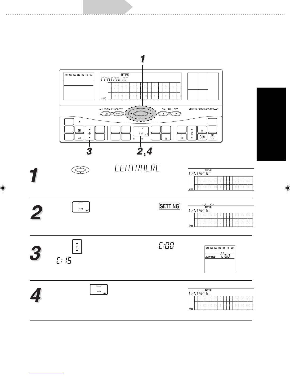
(1)Central remote controller address setting
Use the following procedure to set the central remote controller address.
Test operation
ACL
CLOCK
ADJUST
DAY
TIMER
MODE
TIMER
COPY
DAY OFF
TIME
TIMER
DELETE
TIMER
SET
MEMORY
CENTRAL
CONTROL
OPERATION
MEMORY
GROUP
SETTING SETTING
CHECK
SET
TEST
BACK
DELETE
ZONE
FILTER
RESET
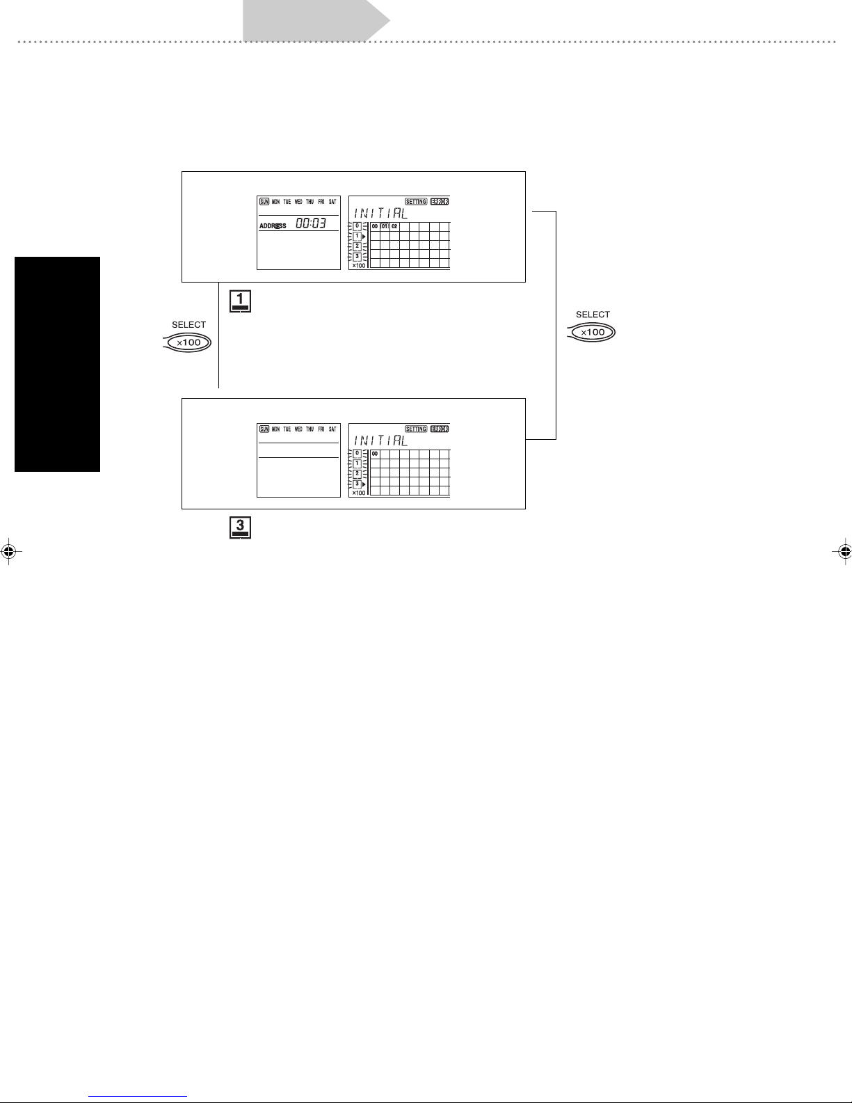
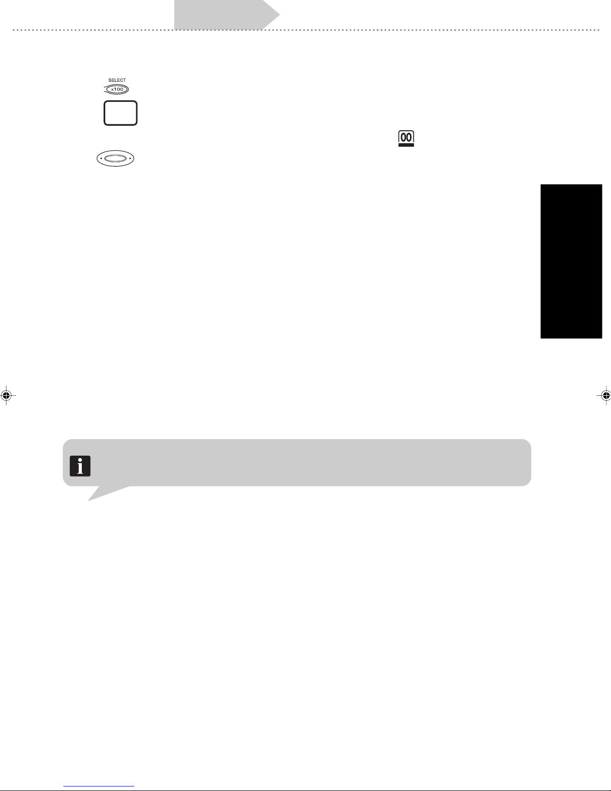
Press to display . Use the
initial setting menu to select central remote control-
ler address setting.
Press
SET
to enter the setting mode. (
will flash and address setting can be made.)
TIME
Press
and select a number between to
MASTER
CONTROL
FAN
TEMP.
ENERGY ANTI
SAVE
ON OFF
CONTROL
FREEZE
3. BASIC OPERATION
that does not duplicate the number of another
central remote controller.
Finally , press
SET
troller address.
to set the central remote con-
15
Page 18

3. BASIC OPERATION
Turn on power Initial setting Clock setting
Group information store
Test operation
(2) System information scanning
Searches all the indoor units connected by the communication cable and store them in the
central remote controller.
ACL
CLOCK
ADJUST
DAY
TIMER
MODE
TIMER
COPY
DAY OFF
TIME
TIMER
DELETE
TIMER
SET
MEMORY
CENTRAL
CONTROL
OPERATION
MEMORY
GROUP
SETTING SETTING
CHECK
SET
TEST
BACK
DELETE
ZONE
FILTER
RESET
Press to display and select
system information scanning. Pre viously stored cen-
tral control numbers will light up.
Press
refrigerant system. The initial value is “99” so use
TIME
SET
and then perform scan to set the final
to select an optional scan final refrigerant sys-
tem number from 99 to 0.
• To delete an operation, press
BACK
to return to
1.
MASTER
CONTROL
FAN
TEMP.
ENERGY ANTI
SAVE
ON OFF
CONTROL
FREEZE
Press
SET
will flash and system information scanning will begin. Once the indoor scan has been completed, the
display in 1 will return.
16
again and and
Page 19
Turn on power Initial setting Clock setting
Group information store
Test operation
Notes • The system information scanning requires approximately 30 minutes to complete. (The time will depend
upon the number of indoor units connected.)
• Stop the operation of the indoor unit before performing system information scanning.
• The system information scanning can be interrupted and cancelled by pressing
• If system information scanning is performed, previously assigned central control numbers will be deleted.
• will light up if an error occurs during scanning. Error display is performed for each refrigerant
system.
• The system information scanning will be performed in the following manner when there are multiple
central remote controller.
When system information scanning and manual assignment 2 is performed, other central remote
controllers will show the following display and operations from them will be prohibited.
This display will continue until the system information scanning or the manual assignment 2 is cancelled.
Always perform the following when changing the address on the indoor unit.
• Turn on the power supply again.
(Refer to “3-2-1 Turn on power” for details about turning on the power.)
• Perform system information scanning once again.
DELETE
.
3. BASIC OPERATION
17
Page 20
3. BASIC OPERATION
Turn on power Initial setting Clock setting
Group information store
Test operation
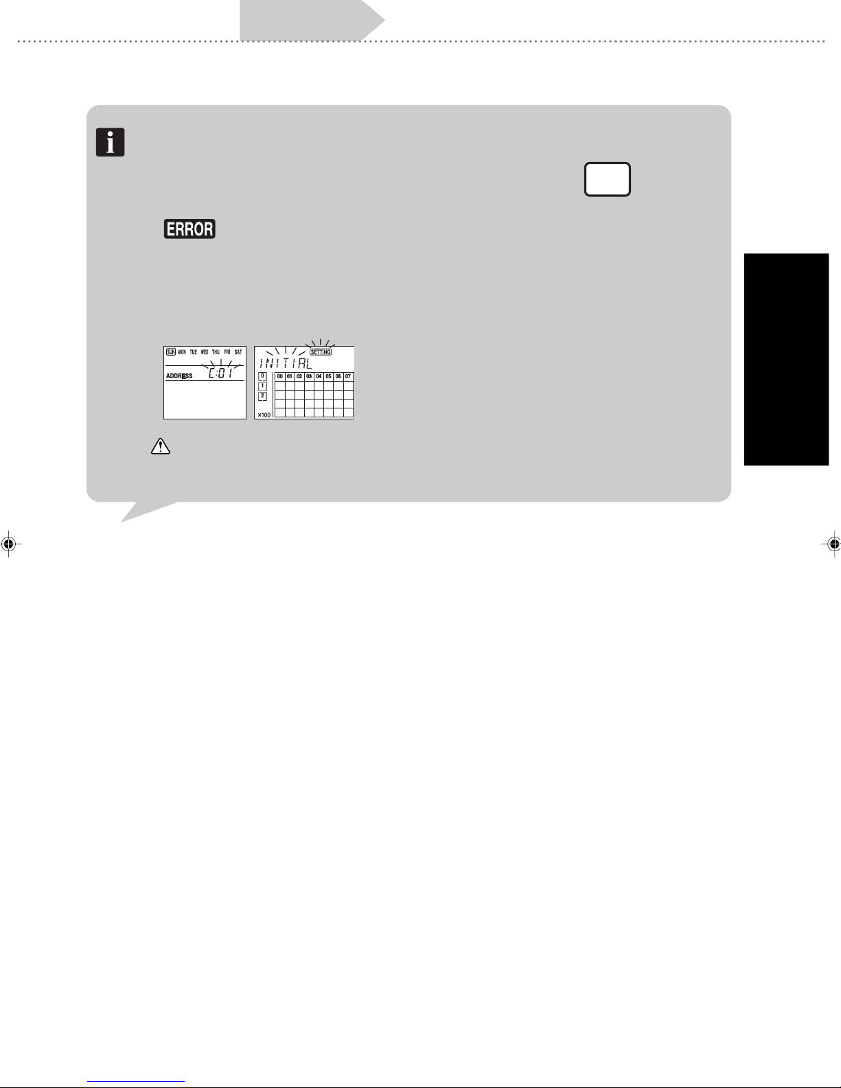
• System information scanning error
An error during the system information scanning will be shown in following manner.
System setting error
▲
flashing: System setting error
Cause of error: System setting has not been
properly performed.
Always wait one minute or more after turning
on the power before starting the initial settings.
▼
Outside setting range error
flashing: Outside setting range error
Cause of error: The address of the indoor unit
has been set outside the range from 0 to 15.
18
Page 21
Turn on power Initial setting Clock setting
• Press to move among the errors.
Group information store
Test operation
• Press
BACK
to cancel the error display and return to the initial setting menu.
• When an error occurs, the number of units with errors will appear in .
• Use to check the address duplication errors and system setting errors for refrigerant
system address and / or indoor unit address for related indoor unit.
(3)Indoor unit storing
The following are the three methods f or storing the remote control group with the central remote
controller. Select any one of them. However, the these storing menus will not be displayed
unless the system information scanning has been completed.
• Automatic storing
This automatically stores the remote control group with the central remote controller . Storing of all
remote control groups connected by communication cab le is performed automatically in ascending order of the refrigerant system addresses and indoor unit addresses.
• Manual storing 1
A remote control group can be optionally stored to a central control number. Here , the refrigerant
system addresses and indoor unit addresses are specified and stored one at a time to selected
central control numbers.
• Manual storing 2
The remote control group is stored in sequence of the standard remote controllers as they are
operated. Sending the refrigerant system address and indoor unit address of the remote control
group actually operated to the central remote controller performs the storing.
3. BASIC OPERATION
Note After group information store has been performed, system information store is performed. All the
currently saved group information store data is deleted.
19
Page 22
3. BASIC OPERATION
Turn on power Initial setting Clock setting
■Automatic storing
Group information store
Test operation
ACL
CLOCK
ADJUST
DAY
TIMER
MODE
TIMER
COPY
DAY OFF
TIME
TIMER
DELETE
TIMER
SET
MEMORY
CENTRAL
CONTROL
OPERATION
MEMORY
GROUP
SETTING SETTING
CHECK
SET
TEST
BACK
DELETE
ZONE
FILTER
RESET
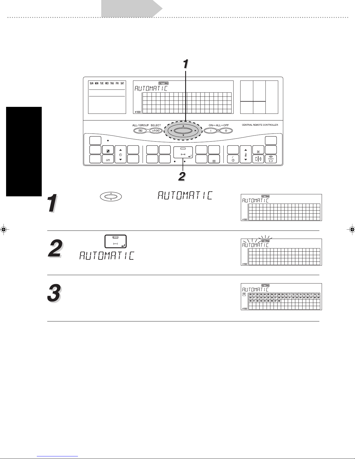
Press to display . Use
the initial setting menu to select automatic storing.
Press
SET
to start automatic storing.
flashes and the automatic stor-
ing process begins.
The automatic storing process ends in approximately 10 minutes and then automatically returns
to the initial setting menu.
MASTER
CONTROL
FAN
TEMP.
ENERGY ANTI
SAVE
ON OFF
CONTROL
FREEZE
20
Page 23

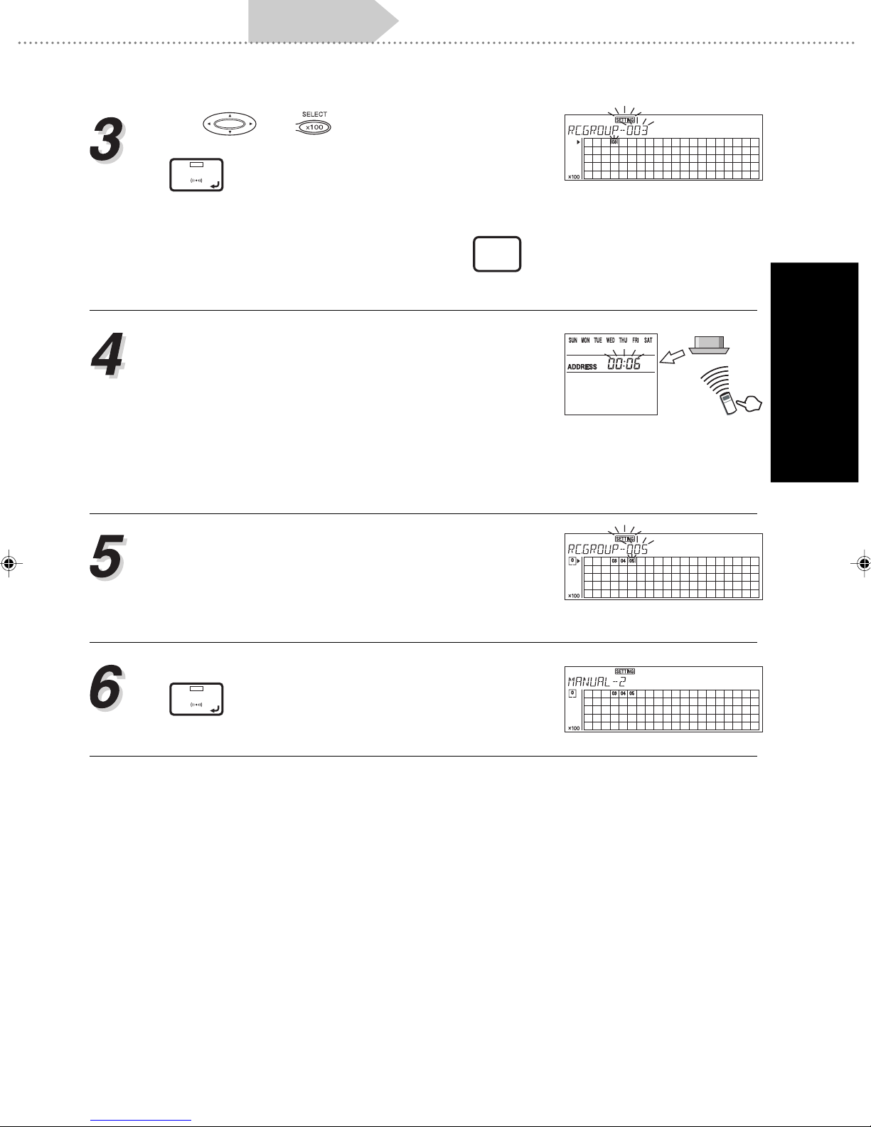
Turn on power Initial setting Clock setting
■Manual storing 1
Group information store
Test operation
ACL
CLOCK
ADJUST
DAY
TIME
TIMER
MODE
TIMER
COPY
DAY OFF
TIMER
DELETE
TIMER
SET
MEMORY
CENTRAL
CONTROL
OPERATION
MEMORY
GROUP
SETTING SETTING
CHECK
SET
TEST
BACK
DELETE
ZONE
FILTER
RESET
Press to display . Use the
initial setting menu to select manual storing 1.
Press
SET
to move to the storing execution
screen.
Use and to select the desired central
control number from the 100 segments.
MASTER
CONTROL
FAN
TEMP.
ENERGY ANTI
SAVE
ON OFF
CONTROL
FREEZE
3. BASIC OPERATION
• Pressing
DELETE
cel the storing of the central control number.
TIME
Press
and to select the address of the remote
control group to be stored in the central contr ol number selected in 3. (Of the indoor units making up the
remote control group, only the refrigerant system
addresses and indoor unit addresses of the indoor
unit with remote addresses of “0” will be displa yed.)
Storing is performed at the time of selection.
at the time of selection will can-
21
Page 24
3. BASIC OPERATION
Turn on power Initial setting Clock setting
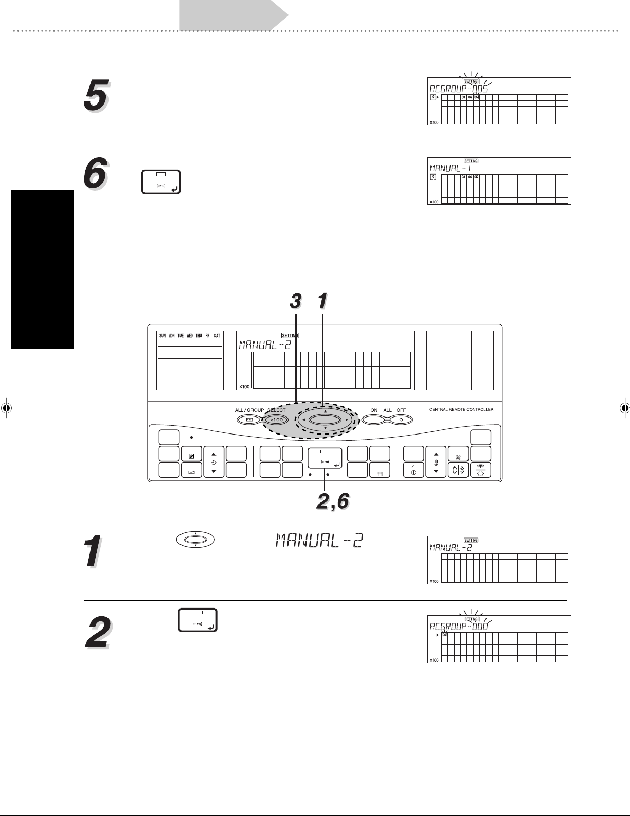
Repeat steps 3 and 4 to continue storing in sequence.
Once all the storing has been completed, press
SET
to return to the initial setting menu.
■Manual storing 2
Group information store
Test operation
ACL
CLOCK
ADJUST
DAY
TIMER
MODE
TIMER
COPY
DAY OFF
TIME
TIMER
DELETE
TIMER
SET
MEMORY
CENTRAL
CONTROL
OPERATION
MEMORY
GROUP
SETTING SETTING
CHECK
SET
TEST
BACK
DELETE
ZONE
FILTER
RESET
Press to display . Use the
initial setting menu to select manual storing 2.
Press
SET
to move to the storing execution
screen.
MASTER
CONTROL
FAN
TEMP.
ENERGY ANTI
SAVE
ON OFF
CONTROL
FREEZE
22
Page 25
Turn on power Initial setting Clock setting
Use and to select the desired central
control number from the 100 segments, press
SET
. (The central remote controller will be in a
wait mode for a signal from the indoor unit.)
• If you wish to delete the operations for manual stor-
Group information store
Test operation
ing 2 using this storing screen, press
BACK
to
return to screen 1.
Operation is performed for the indoor units that are
to be stored to the central control number that was
selected in 3. (You must go to the actual location of
installation and perform the operation from the standard remote controller.) By performing the operation, the operating inf ormation is sent to the central
remote controller and is stored in the central control number that was selected on the central remote
controller .
Repeat the step 4. Use the standard remote controller to turn the indoor units on in sequence. Each
time the central control number is stored using the
operation in step 4, it will be automaticall y increased
by 1.
3. BASIC OPERATION
Once all the storing has been completed, press
SET
to return to the initial setting menu in 1.
23
Page 26

3. BASIC OPERATION
Turn on power Initial setting Clock setting
Group information store
Test operation
3-2-3. Clock setting
The clock setting can be used to set the current time or set various setting of the central remote
controller.
ACL
CLOCK
ADJUST
TIMER
MODE
TIMER
COPY
DAY
DAY OFF
TIME
TIMER
DELETE
TIMER
SET
MEMORY
CENTRAL
CONTROL
OPERATION
MEMORY
GROUP
SETTING SETTING
CHECK
SET
TEST
BACK
DELETE
ZONE
FILTER
RESET
TEMP.
ENERGY ANTI
SAVE
ON OFF
FAN
CONTROL
MASTER
CONTROL
FREEZE
Press
Press
CLOCK
to start the clock setting.
ADJUST
TIMER
to select 24-hour or 12-hour display.
MODE
The digits below the clock mean Clock Display settings.
: 24 Hour Clock Display
: 12 Hour Clock Display 1
: 12 Hour Clock Display 2
Year / Month / Day setting is performed. Use
to select the items to be changed and perform the
setting with .
Press
TIME
and set the current time.
24
Page 27

Turn on power Initial setting Clock setting
Group information store
Test operation
Press
Press
DAY
ON OFF
and set the current day.
and set the beep enable / disable set-
ting.
Finally, press
Note If there is an indoor unit that is operating based on the timer of the central remote controller. The
operations of the time setting mention above will be limited to items at 2 and 6.
CLOCK
to end the clock setting.
ADJUST
3. BASIC OPERATION
25
Page 28

3. BASIC OPERATION
Turn on power Initial setting Clock setting
Group information store
Test operation
3-2-4. Group information store
It is necessary to do group information store before group control is conducted with the central
remote controller.
The following shows the procedure of group information store.
ACL
CLOCK
ADJUST
TIMER
MODE
TIMER
COPY
DAY
DAY OFF
TIME
TIMER
DELETE
TIMER
SET
MEMORY
CENTRAL
CONTROL
OPERATION
MEMORY
GROUP
SETTING SETTING
CHECK
SET
TEST
BACK
DELETE
ZONE
FILTER
RESET
TEMP.
ENERGY ANTI
SAVE
ON OFF
FAN
CONTROL
MASTER
CONTROL
FREEZE
••
• To do group information store
••
Press
GROUP
to enter the group information store
SETTING
mode.
Select the group number whose group information
store need to be performed with and set by
pressing
SET
.
Press to select the central control number
to be stored in the selected group. Press
store.
To continue group information store, press
SET
to
BACK
to return to the group number selection screen of 1
and repeat steps 2 and 3. To complete the gr oup in-
formation store, press
tion screen shown in step 1.
26
GROUP
in the group selec-
SETTING
Page 29

Turn on power Initial setting Clock setting
••
• To delete the stored information in group
••
Group information store
Test operation
Press
GROUP
to enter the group information store.
SETTING
Use to select the group whose stored infor-
mation is to be deleted and then press
SET
to
set it.
DELETE
If
is pressed at this time, all the central con-
trol numbers registered in the selected group will
be deleted.
Use to select the central control number in
the group selected in step 2 and press
DELETE
to
delete it.
Repeat step 3 to continue deleting the stored central control number in the same group.
3. BASIC OPERATION
If you wish to delete the stored information in other
group, press
BACK
to return to screen of step 1.
Repeat steps 2 and 3.
T o end the deletion of the stored group inf ormation,
press
GROUP
SETTING
.
27
Page 30

3. BASIC OPERATION
Turn on power Initial setting Clock setting
3-2-5. Test operation
Group information store
Test operation
CLOCK
ADJUST
TIMER
MODE
TIMER
COPY
ACL
DAY
DAY OFF
TIME
TIMER
DELETE
TIMER
SET
MEMORY
CENTRAL
CONTROL
OPERATION
MEMORY
GROUP
SETTING SETTING
CHECK
SET
TEST
BACK
DELETE
ZONE
FILTER
RESET
TEMP.
ENERGY ANTI
SAVE
ON OFF
FAN
CONTROL
MASTER
CONTROL
FREEZE
Remote control group operation settings are performed in the control mode. The following procedure for the setting is the same for an y of the control modes: Individual control mode / Group control
mode / All control group.
Push to select control mode from among Individual control mode / Group contr ol mode / All con-
trol.
• When Individual control mode is selected, use
and to select the desired central con-
trol number, then go to step 3.
• When Group control mode is selected use
to select the desired group number , then go to step
3.
• When All control mode is selected, go directly to
step 3.
Press
and will light up. The operation
TEST
setting selected in 1 is applied to the selected control mode.
28
Page 31

Turn on power Initial setting Clock setting
Group information store
Test operation
Press
SET
to send the signal and test operation
setting is sent to the indoor unit. will flash as
the signal is being transmitted.
• 60 minute test operation starts.
• To interrupt the test operation, use the same operations as for stopping normal operation.
• It is possible is to change the settings for the operation mode (heating / cooling) and fan setting.
Once the signal has been transmitted, the seg-
ment will flash and LED
SET
will go out. The in-
door unit will start the test operation.
Note If the test operation is stopped midway, use the operation shown in 3 above and press
ON OFF
3. BASIC OPERATION
.
will come on and the operations in 4 will be sent to the indoor unit the same way. The test
operation will stop.
29
Page 32
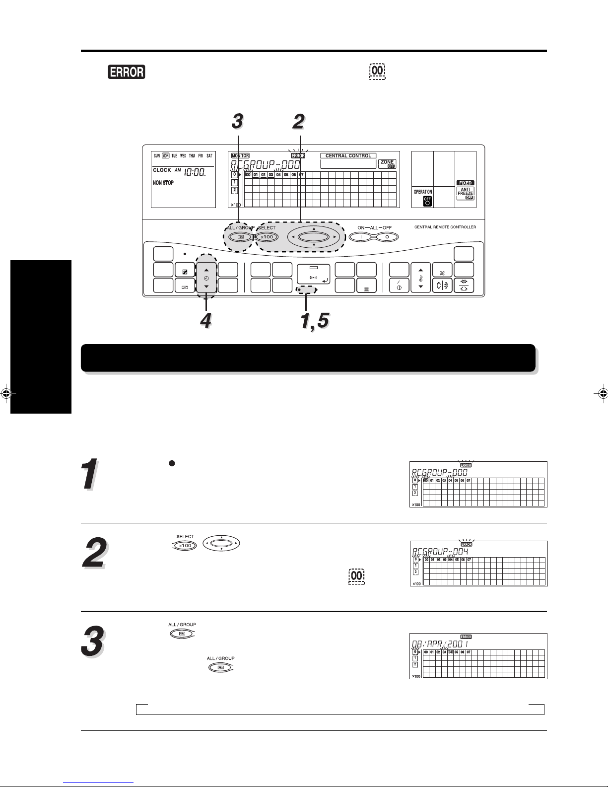
4. ERROR DISPLAY
4. ERROR DISPLAY
If the and the number for the central control number flash during operation, there is an
error at the relevant remote control g roup. Start the error monitor , identify the error and remove the
cause.
ACL
CLOCK
ADJUST
TIMER
MODE
TIMER
COPY
DAY
DAY OFF
TIME
TIMER
DELETE
TIMER
SET
MEMORY
CENTRAL
CONTROL
OPERATION
MEMORY
GROUP
SETTING SETTING
CHECK
SET
TEST
BACK
DELETE
ZONE
FILTER
RESET
TEMP.
ENERGY ANTI
SAVE
ON OFF
FAN
CONTROL
MASTER
CONTROL
FREEZE
4-1. ERROR MONITOR
When the error monitor is started, the following can be performed.
• The error code for each remote control group (indoor units) is display ed.
• Up to two of the past error codes are displayed for each of the indoor units , the outdoor units and
the central remote controller group.
Press
The LCD changes to the error monitor screen.
Press to select the central control
number for which its details of the error contents
are to be confirmed. (The number of the causing the error is flashing.)
Press to select the display mode for the error
code.
to start the error monitor.
CHECK
Each press of will switch the display as shown
below.
▲
Current error code → First previous error code → Second previous error code
30
Page 33

TIME
Press
Continue pressing
to select the indoor units in the remote control group selected in 3.
TIME
, the error codes for the outdoor unit and the central re-
mote controller are displayed. Each of the displays is shown below.
Indoor unit
error display
▲
• If there have been multiple
“The refrigerant system address and indoor unit
errors for one unit, continu-
address are displayed.”
▲
TIME
ally pressing
TIME
will dis-
▼
Outdoor unit
error display
“Refrigerant system address” and “-0” are displayed.
▲
TIME
▼
Central remote
control error
display
The “C” code and the central remote controller
address are displayed.
▲
TIME
play the error codes in sequence. When all the error
codes have been displayed, the display will
switch to the next unit.
• If there is no error in the
central control number selected in 3, the display will
TIME
not change when
is
pressed. “00” displayed
means “no errors”.
4. ERROR DISPLAY
Press
CHECK
again to end the error monitor.
31
Page 34
4-2. ERROR CODES
The following explains the meaning of each of the error codes.
4. ERROR DISPLAY
Error
Code
00
01
02
03
04
05
06
07
08
09
0A
0B
0C
0D
0E
0F
10
11
12
13
14
15
16
17
18
19
1A
1B
1C
1D
1E
1F
20
21
22
23
24
25
26
27
28
If indoor unit error
No error
–
Model information abnormal
Microcomputer error
Power supply frequency abnormal
–
EEPROM access error
EEPROM deletion error
–
Room temperature
thermistor error
Heat exchanger thermistor
(middle) error
Heat exchanger thermistor
(inlet) error
Heat exchanger thermistor
(outlet) error
Blower temperature thermistor
error
–
–
–
Drain abnormal
Room temperature abnormal
Fan error
–
–
–
–
Standard wired remote control
communication error
–
–
–
–
–
–
Transmission error
–
–
–
–
–
–
–
–
–
If outdoor unit error
S series V series
No error
–
Model information abnormal
Circuit board error 1
Power supply frequency error
Reverse phase blocker error
EEPROM access error
EEPROM deletion error
–
Compressor 1 error
Compressor 2 error
Compressor 3 error
–
Discharge temperature thermistor 1 error
Discharge temperature thermistor 2 error
Discharge temperature thermistor 3 error
Outdoor temperature thermistor error
Heat exchanger inlet thermistor 1 error
Heat exchanger inlet thermistor 2 error
Heat exchanger inlet thermistor 3 error
Heat exchanger outlet thermistor 1 error
Heat exchanger outlet thermistor 2 error
Heat exchanger outlet thermistor 3 error
Suction temperature thermistor error
–
Discharge pressure sensor error
Liquid pressure sensor error
Suction pressure sensor error
Oil sensor error
–
–
Transmission error
–
Discharge temperature 1 error
Discharge temperature 2 error
Discharge temperature 3 error
High-pressure error
Low-pressure error
–
Oil recovery error
Pump down error
No error
–
–
–
–
Reverse phase blocker
error
Outdoor PCB unit error
–
–
Compressor error
–
–
–
–
Outdoor unit thermistor
error
–
–
–
–
–
–
–
–
–
–
Sensor error
(except thermistor)
–
–
–
–
–
Transmission error
–
–
–
–
Operation error
(Pressure/temperature)
–
–
–
Pump down error
If central remote controller
error
No error
–
Circuit board error (Control panel)
Circuit board error
(Transmission adaptor)
Memory error
Node setting error
Parallel communication error
–
–
–
–
–
–
–
–
–
–
–
–
–
–
–
–
–
–
–
–
Initial setting error
Connection error
Initial setting error
Manual store 2 error
Transmission error
–
Software error (Output)
Software error (Input)
–
–
–
–
–
–
32
Page 35
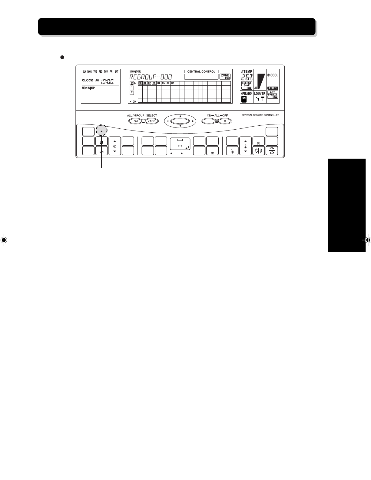
4-3. ALL CLEAR SWITCH
Press
ACL
to restart the central remote controller.
ACL
CLOCK
ADJUST
DAY
DAY OFF
TIME
TIMER
DELETE
TIMER
SET
MEMORY
OPERATION
MEMORY
SETTING SETTING
TIMER
MODE
TIMER
COPY
ACL Switch
CENTRAL
CONTROL
GROUP
CHECK
SET
TEST
BACK
DELETE
ZONE
FILTER
RESET
MASTER
CONTROL
FAN
TEMP.
ENERGY ANTI
SAVE
ON OFF
CONTROL
FREEZE
4. ERROR DISPLAY
33
Page 36
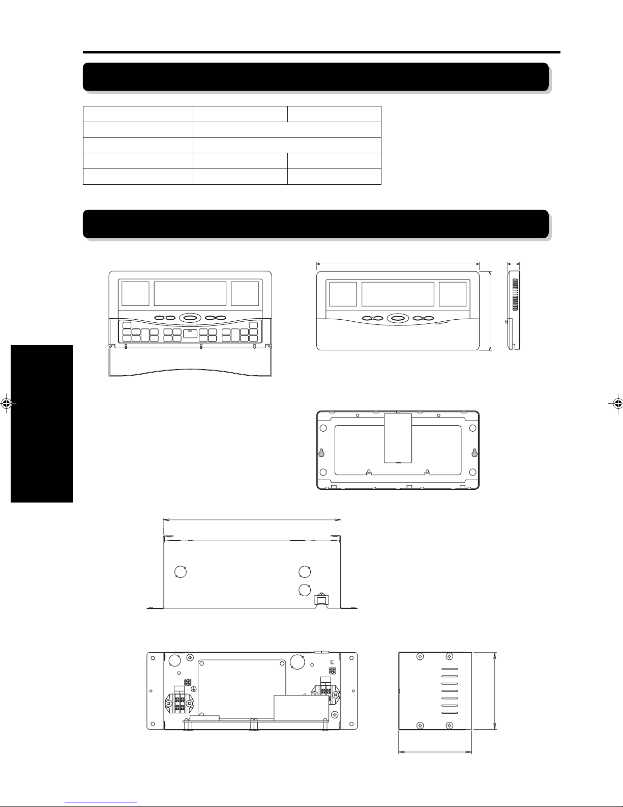
5. SPECIFICATIONS
5-1. SPECIFICATIONS
5. SPECIFICATIONS
Operation panel
Supply power 50 — 60 Hz 220 — 240 V
Power consumption (W) 4.8 W
Size (H × W × D mm) 143 × 296 × 22 (107) × 288 × 100
Weight (g) 550 1300
Communication adapter
5-2. DIMENSIONS
296
Front View Side View
22
143
OPERATION PANEL
POWER
220-240V
12
243
TRANS
MISSION
12
Rear View
TRANSMISSION ADAPTOR
106.6
34
100
Page 37

Page 38

P/N9367842018-06
 Loading...