

Page 1
PART NO. 9374584048-02
INSTALLATION MANUAL
For authorized service personnel only.
VRF SYSTEM
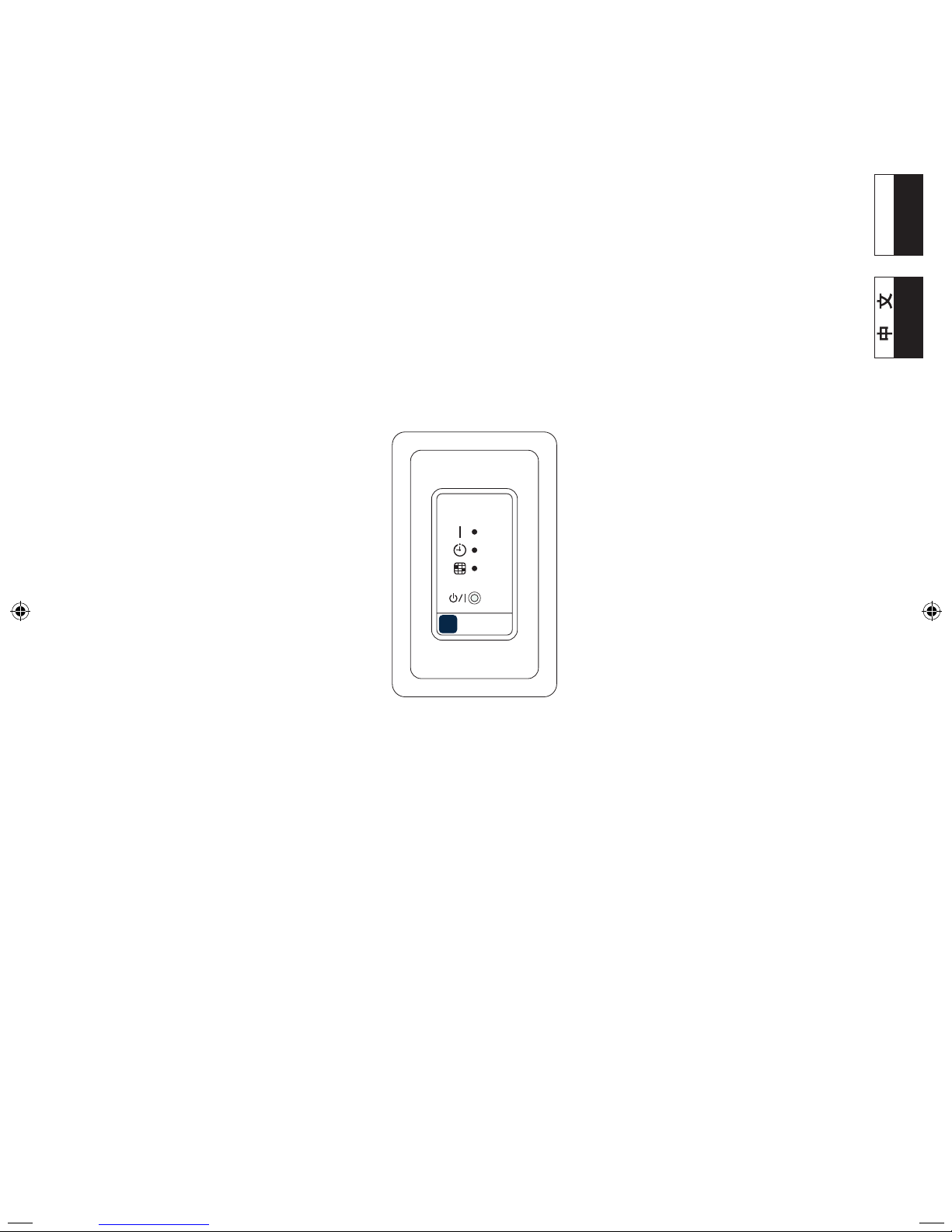
IR RECEIVER UNIT
UTB-
*
WB
Contents
1. SAFETY PRECAUTIONS ............................................. 2
2. MAIN UNIT AND ACCESSORIES ................................. 3
3. OPTIONAL PARTS .......................................................3
4. FUNCTIONS AND DIMENSION ................................... 3
5. SELECTING THE INSTALLATION LOCATION ............3
6. INSTALLING THE RECEIVER UNIT
6.1. Select the wiring method ....................................... 4
6.2. Select the installation method ............................... 4
7. WIRING ......................................................................... 5
8. TURNING ON THE POWER ......................................... 7
9. ERROR CODE DISPLAY ..............................................7
English
Page 2
En-2
Do not operate this unit when your hands are wet. •
Touching the unit with wet hands will cause an electric
shock.
If children may approach the unit, take preventive •
measures so that they cannot reach the unit.
CAUTION
This mark indicates procedures which,
if improperly performed, might possibly
result in personal harm to the user or
damage to property.
Pay abundant care when transporting this unit because it •
is a precision device. Improper transportation will cause
trouble.
Do not touch the switches with sharp objects. Doing so •
will cause injury, trouble, or electric shock.
Do not expose this unit directly to water. Doing so will •
cause trouble, electric shock, or heating.
Do not set vessels containing a liquid on this unit. Doing •
so will cause heating, re, or electric shock.
Dispose of the packing materials safely. Tear and dispose •
of the plastic packing bags so that children cannot play
with them. There is the danger of suffocation if children
play with the original plastic bags.
1. SAFETY PRECAUTIONS
The “SAFETY PRECAUTIONS” indicated in this manual •
contain important information pertaining to your safety. Be
sure to observe them.
Details of the operation methods refer to the operating •
manual. Request the user to keep them on hand for future
use, such as for relocating or repairing the unit.
WARNING
This mark indicates procedures which, if
improperly performed, might lead to the
death or serious injury of the user.
Perform electrical work by an authorized service •
personnel in accordance with the installation manual
and the electrical wiring regulations or implementation
regulations of the country. Also do not install this unit by
yourself. Improper electric work will cause electric shock
or a re.
Perform installation work in accordance with the •
installation manual. Request an authorized service
personnel to perform installation work. Do not install this
unit by yourself. Improper installation will cause injury,
electric shock, re, etc.
In the event of a malfunction (burning smell, etc.), •
immediately stop operation, turn off the electrical breaker,
and consult authorized service personnel.
Install a leakage circuit breaker to power supply cable •
in accordance with the related laws and regulations and
electric company standards.
Use a power source exclusively for this unit. Never share •
the power source with other electrical equipment. Doing
so will cause re and electric shock.
Do not install the unit in the following areas:
Do not install the unit near a source of heat, steam, or •
ammable gas.
Area lled with mineral oil or containing a large amount of •
splashed oil or steam, such as a kitchen. It will deteriorate
plastic parts, causing the parts to fall or the unit to leak
water.
Area that generates substances that adversely affect the •
equipment, such as sulfuric gas, chlorine gas, acid, or
alkali. It will cause the copper pipes and brazed joints to
corrode, which can cause refrigerant leakage.
Area containing equipment that generates •
electromagnetic interference. It will cause the control
system to malfunction, preventing the unit from operating
normally.
Area that can cause combustible gas to leak, contains •
suspended carbon bers or ammable dust, or volatile
inammables such as paint thinner or gasoline. If gas
leaks and settles around the unit, it can cause a re.
Do not use the unit for special purposes, such as storing •
food, raising animals, growing plants, or preserving
precision devices or art objects. It can degrade the quality
of the preserved or stored objects.
Install the unit in a well-ventilated place avoiding rains •
and direct sunlight.
Page 3
En-3
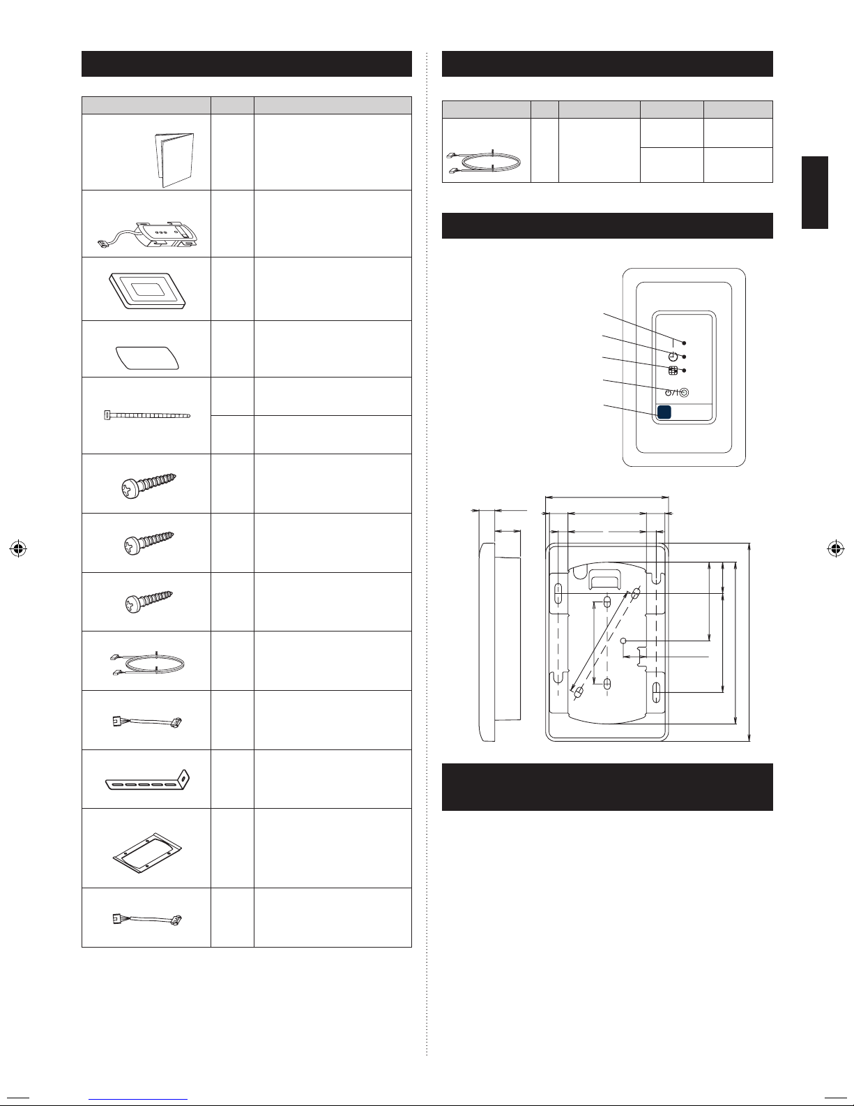
3. OPTIONAL PARTS
Description
Q’ty Application
Part No. Model
Receiver unit
cable C
10m
For
extending
the receiver
unit cable
9378143012
UTB-YWB
9378143036
UTB-TWB
4. FUNCTIONS AND DIMENSIONS
Functions
SIGNAL RECEIVER
OPERATION LAMP (Green)
TIMER LAMP (Orange)
MANUAL AUTO BUTTON
FILTER SIGN LAMP (Red)
Dimensions
11.5
60
57.6
83.5
22.9
118.4
72.4
18.5
13.6
57.4
13.6
7.27.2
17
90
145
Unit:mm
5. SELECTING THE INSTALLATION
LOCATION
Consult the user and determine the installation location
according to the following:
(1) The receiver unit wiring can be extended up to 10 m.
(To extend the wiring, purchase the optional receiver unit
cable C.)
(2) The signal reception angle of the receiver unit is shown in
the following gures.
(3) Do not install the receiver unit near a uorescent light.
(The unit must be at least 1 m away from a light source.)
(4) Do not install the receiver unit where it will be exposed to
direct sunlight.
(5) Do not install the receiver unit where it will be exposed
directly to the airow from the indoor unit.
2. MAIN UNIT AND ACCESSORIES
Description Q’ty Application
Installation manual
1
This book
Receiver unit
1
For receiving the signal
from the wireless
remote controller
Cover
1
For receiver unit
Insulation
1
For receiver unit
Binder
Small
1
For receiver unit
Medium
1
For receiver unit
Screw (M4 × 20mm)
2
For installing receiver
unit to wall, etc.
Screw (M4 × 12mm)
1
For attaching the hook
metal to the holder cover
Screw (M4 × 10mm)
2
For attaching the hook
metal to the indoor unit
Receiver unit cable A
5m
For connecting PCB of
indoor unit to receiver unit
Receiver unit cable B
15cm
For connecting PCB of
indoor unit to receiver unit
Hook metal
1
For installing receiver
unit to indoor unit
Bracket (cover)
1
For receiver unit
Receiver unit cable D
15cm
For connecting PCB of
indoor unit to receiver unit
Page 4

En-4
Do not touch the circuit board and circuit board parts •
directly with your hands.
Otherwise, injury or electric shock could result.
Tightening the mounting screws too tight will damage the •
case of this unit.
6.1. Select the wiring method
Method 1 From the top of the receiver unit: No additional
work is necessary.
Method 2 From behind the receiver unit: Perform the
following procedure to route the wiring behind
the receiver unit.
Screw
Holder
(PCB)
Holder cover
1
2
1
1
Remove the screw.
2
Remove holder (PCB)
from holder cover.
1
Route the wiring as
shown in the gure.
2
1
Hook
Holder cover
Screw
1
Reattach holder cover. (Make sure that the hook on
the holder cover is caught on the holder [PCB].)
2
Fix holder (PCB) by the screw.
6.2. Select the installation method
Method 1 Receiver unit embedded in a wall or ceiling:
Refer to “I. Embedding the receiver unit.”
Method 2 Receiver unit attached to a wall or ceiling:
Refer to “II. Attaching the receiver unit.”
Method 3 Receiver unit cannot be imbedded in or attached
to a wall or ceiling: Refer to “III.
Attaching the receiver unit to the indoor unit.”
I. Embedding the receiver unit
Unit: mm
58-62
120-140
Screws (M4 x 20mm)
Wall or ceiling
1
2
2
1
Make a hole in the wall
or ceiling.
(Depth: 25 mm or more)
1
Afx the insulation to the
holder cover.
2
Attach the holder cover
and the bracket (cover)
to the wall or ceiling
with the screws (included
with the standard parts).
Ex. Installation on the wall
5 m
120°
Indoor unit
Ceiling
5 m
Receiver
unit
Remote
controller
Signal reception
angle
Ex. Installation on the ceiling
5 m
120°
Indoor unit
Ceiling
Remote
controller
5 m
Receiver unit
Signal reception angle
If the wiring length is 10 m, replace with receiver unit cable C
(optional parts).
Receiver unit cable A (5m).
6. INSTALLING THE RECEIVER UNIT
WARNING
Always use the accessories and specied installation •
work parts. Check the state of the installation parts. Not
using the specied parts will cause units to fall off, water
leakage, electric shock, re, etc.
Install at a place that can withstand the weight of the unit •
and install positively so that the unit will not topple or fall.
When installing this unit, make sure that there are no •
children nearby.
Otherwise, injury or electric shock could result.
After installing this unit, perform the test run to conrm •
that the unit is operating properly. Then, explain the
operation of this unit to the customer.
Install a circuit breaker. •
Otherwise, electric shock or re could result.
CAUTION
Do not set the DIP switch or rotary switch of this unit •
except as specied in this installation manual or the
instruction manual supplied with the air conditioner.
Setting the switches other than specied will cause an
accident or trouble.
Before opening the case of this unit, completely discharge •
static electricity charged on your body. Not doing so will
cause trouble.
1
2
3
1
2
Page 5

En-5
Cover
Bracket
(cover)
Cover
1
1
2
1
Install the cover.
Hook the 2 projections on the top of the cover onto
the bracket (cover), and then hook the projection on
the bottom of the cover onto the bracket (cover).
2
Make sure that there is no gap between the cover and
the wall or ceiling.
II. Attaching the receiver unit
Screw
Holder
(PCB)
Holder cover
1
2
1
Remove the screw.
2
Remove holder (PCB)
from holder cover.
1
Cut the projections in
the areas indicated with
a and remove them.
(Be careful not to injure
yourself on the cut edges
of the holder cover.)
1
2
2
Screws (M4 x 20mm)
Wall or
ceiling
Hook
1
2
1
Afx the insulation to
the holder cover.
2
Attach the holder cover
to the wall or ceiling with
the screws (included
with the standard parts).
1
Reattach holder cover.
(Make sure that the
hook on the holder cover
is caught on the holder
[PCB].)
2
Fix holder (PCB) by the
screw.
III. Attaching the receiver unit to the indoor unit (EXAMPLE
AR07-18)
1
2
Screw
1
Remove the screw.
2
Remove holder (PCB)
from holder cover.
1
Cut the projections in
the areas indicated with
a and remove them.
(Be careful not to injure
yourself on the cut
edges of the holder
cover.)
Screw
(M4 x 12mm)
1
2
Screws
(M4 x 10mm)
1
1
1
Afx the insulation to the
holder cover.
2
Attach the hook metal to
the holder cover with
the screw (included with
the standard parts).
1
Attach the hook metal to
the indoor unit with the
screw(s).
7. WIRING
WARNING
Before starting installation work, turn off the power of this •
unit and the connection destination. Do not turn on the
power again until installation is completed. Otherwise, it
will cause electric shock or re.
Use the accessories or specied power cable and •
connection cables. Do not modify power cable and
connection cables other than those specied, do not use
extension cables, and do not use independent branch
wiring. The allowable current will be exceeded and cause
electric shock or re.
Install the connection cables securely to the terminal •
board. Conrm that external force is not applied to the
cable. Use connection cables made of the specied
cable. If intermediate connection or insertion xing are
imperfect, it will cause electric shock, re, etc.
When connecting the power cable and communication •
cable, layout the wiring so that the cover of this unit is
securely xed. If the cover is imperfectly xed, it may
cause re or overheating of the terminals.
Perform ground work positively. Do not connect the •
ground cable to a telephone ground cable, water pipe, or
conductor rod.
Always fasten the outside covering of the connection •
cable with the cable clamp. (If the insulator is chafed,
electric leakage may occur.)
When performing cable wiring work, be sure that it does •
not touch the user. Doing so will cause injury or electric
shock.
If any cable is damaged, do not repair or modify it •
yourself. Improper work will cause electric shock or re.
3
1
2
3
4
123
4
Page 6

En-6
To remove the control box cover, refer to the installation
manual of the indoor unit.
Connect receiver unit cable B to CN13 on the PCB.
Route the receiver unit cable using the same method for
the remote controller cables as described in the installation
manual of the indoor unit.
Fasten the receiver unit medium binder (included with the standard
parts), which is used for clamping cables, on the insulating tube
.
Fasten the EMI lter of receiver unit cable B to the surrounding
cables with the small binder (included with the standard parts)
so that it does not contact other electrical parts.
EXAMPLE : Slim Duct
EXAMPLE : Compact Duct
Screw
Screw
Receiver unit
cable B
CN13
1
Remove the control box
cover of indoor unit
accordance with
installation manual.
1
Connect receiver unit
cable B to CN13 on the
PCB of indoor unit.
Receiver
unit cable B
Receiver
unit cable A
Binder small
(ACCESSORIES)
Binder medium
(ACCESSORIES)
Screw
Screw
1
Connect receiver unit
cable A to receiver unit
cable B.
1
Reattach the control
box cover.
3 4
1 2
Receiver unit terminal
(CN18)
Controller
PCB
Core
Clamp
Use 7 pins for receiver unit
cable. (Receiver unit cable D)
At first, connect the receiver
unit cable to the controller PCB.
Attach the core that comes
between controller PCB and
the clamp.
Use conduit hole when external output cable is used.
1
2
3
4
Bundle and fasten
the excess wiring.
Ceiling
Indoor unit
If the wiring length is 10 m, replace with receiver
unit cable C (optional parts).
Receiver unit
cable
A (5m)
Receiver
unit
MAX. 10 m
CONNECT
Heat shrink
tubing
(ø25 L130)
Connect the cables, and then use heat shrink tubing
to protect the connection from dust and water droplets.
After shrinking
both ends of the
heat shrink
tubing, seal the
ends with electrical tape.
Provide a trap in the receiver
unit wiring.
(To prevent water droplets
from entering the receiver unit)
EXAMPLE
CAUTION
Do not bind up the power cable together with the •
transmission cable or remote controller cable. It will cause
erroneous operation.
When performing wiring work, be careful not to damage •
the cable or injure yourself. Also, connect the connectors
securely. Loose connectors will cause trouble, heating,
re, or electric shock.
Install the indoor and outdoor units, power cable, signal •
cable and remote control cable 1 m away from television
and radio to avoid distorted images and noise.
Perform wiring so that water does not enter this unit along •
the external wiring. Always install a trap to the wiring
or take other countermeasures. Otherwise it will cause
trouble or electric shock or re.
Conrm the name of each unit and name of each terminal •
board of the unit and connect the wiring in accordance
with the directions given in the manual so that there is no
incorrect wiring. Incorrect wiring will damage the electric
parts and cause smoke and re.
When installing the connection cables near a source of •
electromagnetic waves, use shielded cable.
Otherwise, a breakdown or malfunction could result.
The terminal screws and ground screws have different •
shapes. Be sure to install the screws in the correct
locations. If the screws are installed in the wrong
locations, the circuit board could be damaged.
Page 7

En-7
8. TURNING ON THE POWER
CAUTION
Before turning on the power, check that the voltage is •
within the rated range. If operated outside the rated
range, erroneous operation cannot be prevented and
cannot be compensated.
(1) Turn on the circuit breakers for the indoor unit and outdoor
unit.
(2) Make sure that the operation lamp and timer lamp are
slowly ashing alternately.
If the auto restart function has been set, the air •
conditioner will operate with the settings immediately
before the power supply was turned off.
If an error has occurred, the lamps on the receiver unit •
will ash quickly to indicate the error code.
9. ERROR CODE DISPLAY
Error display
Error content
OPERATION
LAMP
TIMER
LAMP
FILTER
SIGN LAMP
- - - No error
(1)
(2)
Remote controller
communication error
(1)
(3)
Communication error
between Outdoor unit
(1) (4)
Network communication
error
(1) (5) Scan error
(1) (6)
Peripheral device
communication error
(2) (1) Initial setting error
(2) (6) Address setting error
(2) (8) Other setting error
(3) (1)
Indoor unit power supply
abnormal
(3) (2) Indoor unit main PCB error
(3) (5) Manual auto switch error
(3) (7)
Indoor unit transmission
PCB error
(3) (8)
Network convertor PCB
error
(4) (1) Room temp. sensor error
(4) (2)
Indoor unit Heat Ex. sensor
error
(5) (1) Indoor unit fan motor error
(9) (15) Outdoor unit error
Display Method : 0.1 sec. ON / 0.1 sec. OFF ashing
: 0.5 sec. ON / 0.5 sec. OFF ashing
( ) : Flashing times
OPERATING LAMP and TIMER LAMP will blink alternately.
Page 8

 Loading...