

Page 1
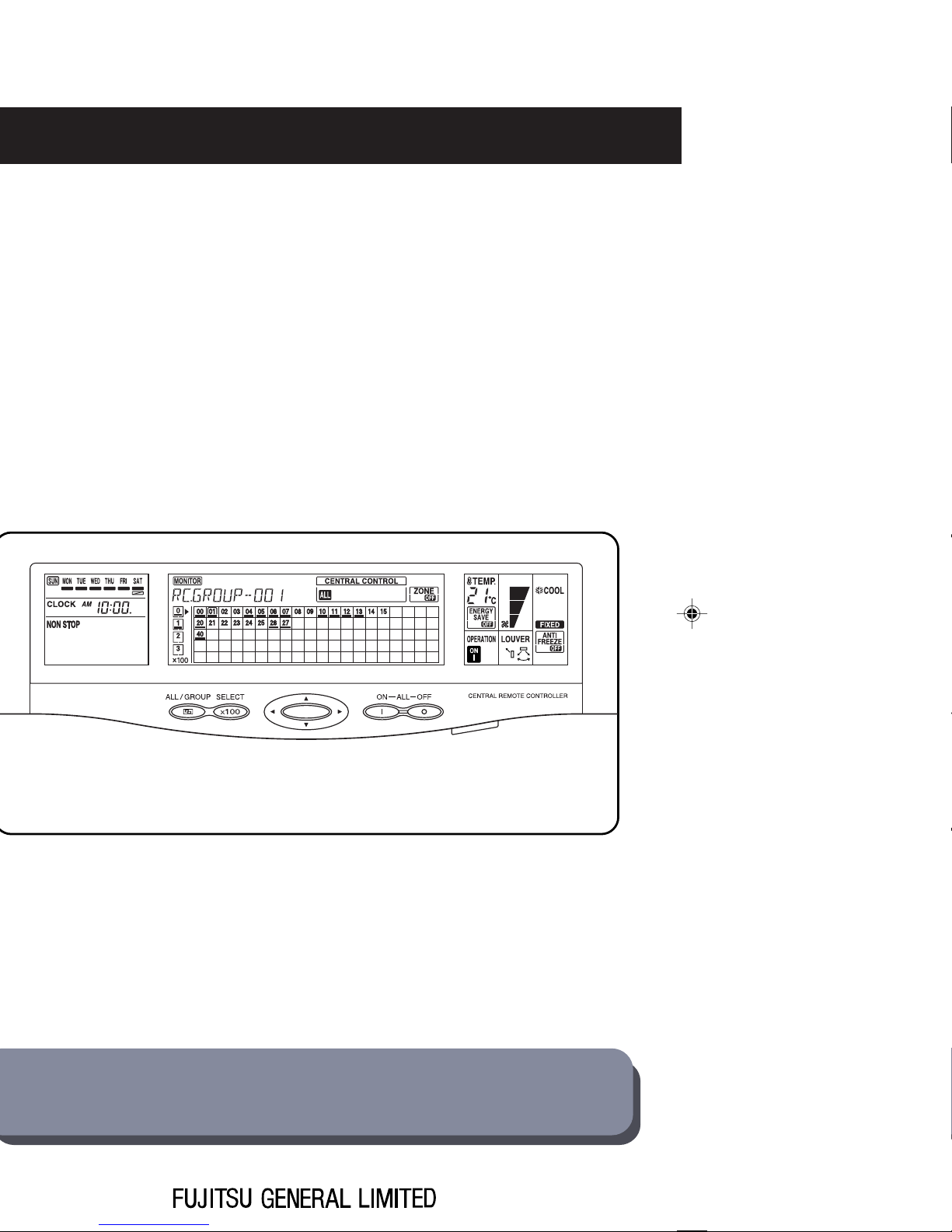
UTB-YCA
UTB-GCA
CENTRAL REMOTE CONTROLLER
OPERATING MANUAL
Page 2

CONTENTS
1. SAFETY PRECAUTIONS .............................................................. 3
2. SYSTEM OUTLINE ....................................................................... 4
2-1. SYSTEM OUTLINE ............................................................................. 4
2-2. FEATURES ......................................................................................... 6
2-3. EXPLANATION OF TERMS ................................................................ 7
2-4. NAMES AND FUNCTIONS OF THE PARTS .................................... 10
3. BASIC OPERATION.................................................................... 12
3-1. BASIC FLOW OF OPERATION ........................................................ 14
3-2. OPERATION DISPLAY MODE .......................................................... 15
3-3. CONTROL MODE ............................................................................. 16
3-4. FUNCTION LIST ............................................................................... 18
4. CENTRAL CONTROL METHOD
(CENTRAL CONTROL AREA) ................................................... 19
4-1. GROUP INFORMATION STORE ...................................................... 20
4-1-1. To do group information store ................................................................. 20
4-1-2. To delete the stored information in group ................................................ 21
4-2. STANDARD REMOTE CONTROL OPERATION PROHIBIT
SETTING........................................................................................... 23
4-3. MEMORY OPERATION .................................................................... 26
4-3-1. Memory operation settings...................................................................... 26
4-3-2. Memory operation ................................................................................... 27
4-4. ZONE SETTING................................................................................ 28
4-4-1. To start zone operation ........................................................................... 28
4-4-2. To end zone operation............................................................................. 29
4-5. FILTER INDICATOR RESET ............................................................. 30
5. OPERATION SETTING METHOD
(OPERATION CONTROL AREA) ............................................... 31
5-1. ALL OPERATION / ALL STOP .......................................................... 32
5-1-1. All operation ............................................................................................ 32
5-1-2. All stop .................................................................................................... 32
5-2. OPERATION / STOP ......................................................................... 33
5-2-1. To start operation .................................................................................... 33
5-2-2. To stop operation .................................................................................... 34
5-3. OPERATING MODE SETTING ......................................................... 35
5-4. TEMPERATURE SETTING ............................................................... 38
5-5. FAN SPEED SETTING ..................................................................... 39
5-6. FLOW DIRECTION SETTING (VERTICAL) ...................................... 41
5-7. FLOW DIRECTION SETTING (HORIZONTAL) ................................ 44
1
Page 3

5-8. SWING SETTING ............................................................................. 46
5-8-1. To select vertical airflow swing operation ................................................ 46
5-8-2. To cancel the vertical airflow swing operation ......................................... 47
5-8-3. To select horizontal airflow swing operation ............................................ 48
5-8-4. To cancel horizontal airflow swing operation ........................................... 49
5-9. ENERGY SAVE OPERATION SETTING .......................................... 50
5-9-1. To select the energy save operation ....................................................... 50
5-9-2. To cancel the energy save operation ...................................................... 51
5-10. ANTI FREEZE OPERATION ............................................................. 53
5-10-1. To select the anti freeze operation .......................................................... 53
5-10-2. To cancel the anti freeze operation ......................................................... 54
6. TIMER SETTING METHOD (TIMER CONTROL AREA) ............ 55
6-1. OFF TIMER ....................................................................................... 56
6-2. ON TIMER ......................................................................................... 58
6-3. WEEKLY TIMER ................................................................................ 60
6-3-1. Setting up the weekly timer operation ..................................................... 60
6-3-2. Starting weekly timer operation............................................................... 64
6-3-3. Canceling the selected time setting ........................................................ 65
6-3-4. Modifying the selected time setting ......................................................... 66
6-3-5. Copying the selected time setting ........................................................... 67
6-3-6. Using the day OFF setting ...................................................................... 68
6-3-7. Precautions during setting ...................................................................... 69
6-4. CLOCK SETTING ............................................................................. 70
7. ERROR DISPLAY ........................................................................ 73
7-1. ERROR MONITOR ........................................................................... 74
7-2. ERROR CODES ............................................................................... 76
7-3. ALL CLEAR SWITCH........................................................................ 77
8. SPECIFICATIONS ....................................................................... 79
8-1. SPECIFICATIONS ............................................................................. 80
8-2. DIMENSIONS ................................................................................... 80
2
Page 4
1. SAFETY PRECAUTIONS
• Before using CENTRAL REMOTE CONTROLLER, read this “SAFETY PRECAUTIONS” thoroughly
to ensure the correct operation.
• This section discribes the important safety information to operate CENTRAL REMOTE CONTROLLER.
• The meanings of “WARNING” and “CAUTION” are explained as follows.
This mark indicate procedures which, if improperly performed, are most
WARNING!
likely to result in the death of or serious injury to the user or service personnel.
PRECAUTIONS
1. SAFETY
CAUTION!
This mark indicates procedures, which might result in personal harm to
the user or damage to property if improperly performed.
WARNING!
• Do not attempt to install this controller by yourself.
• This controller contains no user-serviceable parts. Always consult authorized service
personnel for repairs.
• When moving this controller, consult authorized service personnel for disconnection and
installation of the unit.
• If the problem (burning, smell, etc) occurs, turn off the electrical breaker immediately to
stop operation and then consult the authorized service personnel.
• If the power supply cord becomes damaged, contact your service representative for instruction.
CAUTION!
• Do not expose the controller directly to water.
• Do not operate the controller with wet hands.
• Do not touch the switches with sharp objects.
• Always turn off the electrical breaker whenever cleaning the controller, the air conditioner
or the air filter.
• Ensure that all electronic equipment is at least one meter away from the controller.
• Avoid installing the controller near a fireplace or other heating apparatus.
• When installing the controller, take precautions to prevent access to infants.
• Do not use inflammable gases near the controller.
• At the time of installation, always provide a breaker for electrical leakage.
• Always use fuses with the proper capacity and type.
3
Page 5
2. SYSTEM OUTLINE
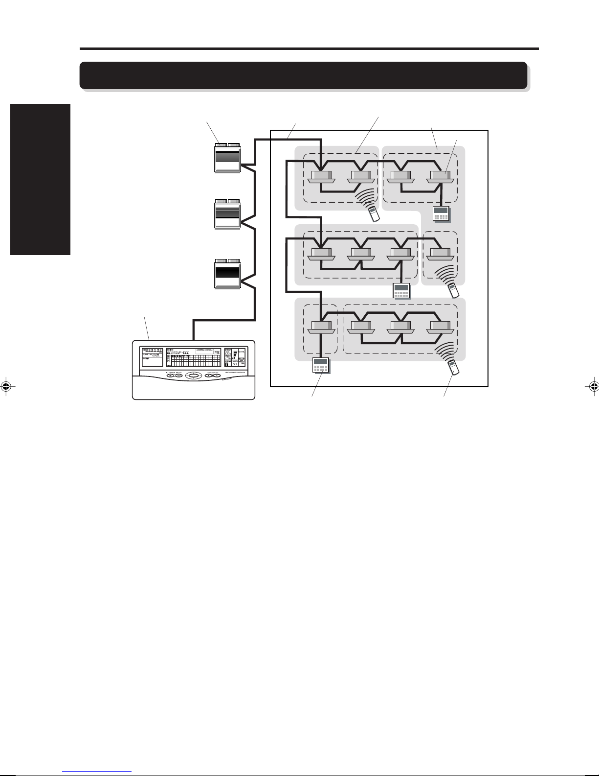
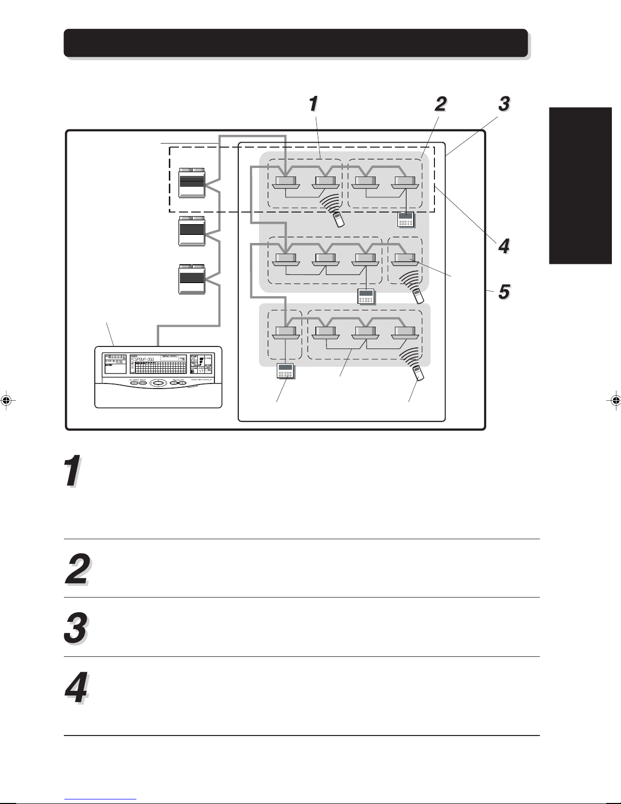
2-1. SYSTEM OUTLINE
2. SYSTEM OUTLINE
Central remote
controller
Outdoor unit
Transmission line
Remote controller group
Group
Indoor unit
Wired remote
controller
Wireless remote
controller
Please consult your sales representative when two or more central remote controllers need to be
installed in one system.
• What is the central remote controller?
The central remote controller allows all the stored remote controller groups (the indoor units) to
be controlled from a remote location.
(Refer to “2-3. EXPLANATION OF TERMS 1” for details about remote controller groups.)
• Three functions of the central remote controller
• CENTRAL CONTROL
The central control provides management of the remote controller groups (the indoor units).
This includes placing restrictions on the standard remote controllers or performing memory operation for easily reproducing operating conditions that have been saved.
• OPERATION CONTROL
The operation control provides a controlled operation (such as to stop operation) of the stored
remote controller groups (the indoor units) in the same manner as the standard remote controller.
• TIMER CONTROL
The timer control allows the starting and stopping of stored remote controller groups and indoor
units through the timer functions in the central remote controller. These timer functions include:
the off timer, on timer and weekly timer.
4
Page 6

• Three control methods of the central remote controller
• Individual control
Provides control for each respective remote controller group.
• Group control
Provides control for each group which is made up of single or multiple previously set remote
control groups.
(Refer to “2-3. EXPLANATION OF TERMS” for details about groups.)
• All control
Provides control for all remote control groups that have been stored in the central remote controller.
2. SYSTEM OUTLINE
5
Page 7
2-2. FEATURES
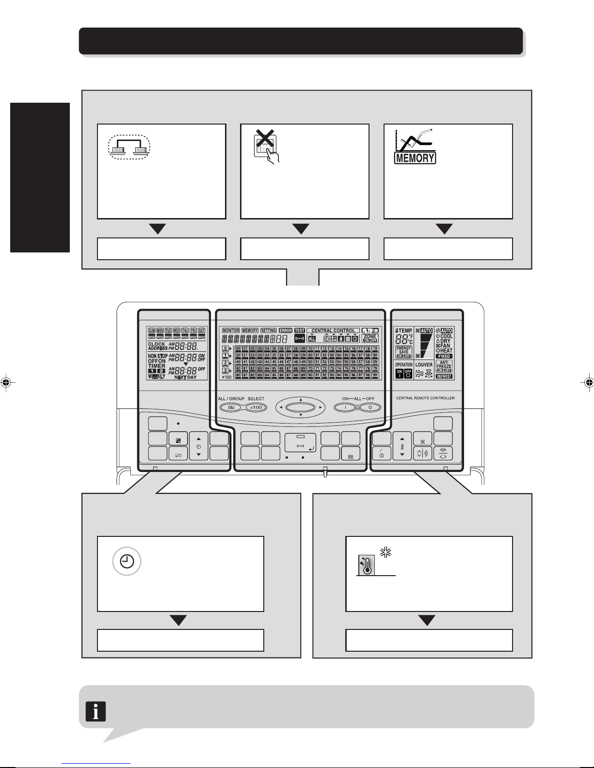
The front panel of the remote controller can be divided by function into three different control areas.
2. SYSTEM OUTLINE
CENTRAL CONTROL
The central control provides management of indoor units. This includes placing restrictions on the standard
remote controllers or performing memory operations.
If multiple remote control
groups are set as one
group,the control of these
remote control groups can be
realized by simply choosing the
group.
4-1. GROUP INFORMATION STORE
TIMER AREA CENTRAL CONTROL AREA OPERATION AREA
By setting the central remote controller,
it is possible to lock the function of the
standard controllers. Items of selections
to lock are all functions, timer mode,
operating mode, temperature setting,
reset filter, and ON/OFF.
4-2. STANDARD REMOTE CONTROL
OPERATION PROHIBIT SETTING
8
7
6
5
4
3
2
Setting contents of central remote
controller are all memorized, so
that each indoor unit can be
operated in the memorized
condition even if the operating
conditions are changed later on.
4-3. MEMORY OPERATION
ACL
CLOCK
ADJUST
TIMER
MODE
TIMER
COPY
DAY
DAY OFF
TIME
TIMER
DELETE
TIMER
SET
MEMORY
CENTRAL
CONTROL
OPERATION
MEMORY
GROUP
SETTING SETTING
CHECK
BACK
DELETE
ZONE
FILTER
RESET
SET
TEST
TEMP.
ENERGY ANTI
SAVE
ON OFF
OPERATION CONTROLTIMER CONTROL
This function is used to provide time-related
controls, such as start and stop, of the indoor unit
by presetting the timer.
SUN
MON
SAT
TUE
FRI
WEDTHU
Weekly timer is equipped as standard
function. (Up to 2 times ON/OFF per day
for one week).
This function provides a controlled operation(such
as to stop operation)of the indoor units in the
same manner as the standard remote controller.
When the temperature of the room becomes low,the
indoor unit will automatically start the heating operation
until the temperature increases to a preset temperature.
5-10. ANTI FREEZE OPERATION6-3. WEEKLY TIMER
Other basic functions
Notes: • Central remote controller can control the indoor unit by all / group / individual.
• UP to 400 indoor units or 64 group can be controlled with one central remote controller.
• UP to 16 central remote controllers can be connected in one system.
FAN
CONTROL
MASTER
CONTROL
FREEZE
6
Page 8
2-3. EXPLANATION OF TERMS
■ Controller related items
Transmission line
Outdoor unit
Central remote
controller
Remote controller group Group
Controller line
Indoor
unit
All
Refrigerant
system
System
2. SYSTEM OUTLINE
Wired remote
controller
Wireress remote
controller
Remote Controller group:
This is the control unit of indoor units that have been connected with one controller line
as well as the control unit of a single indoor unit that has not been connected with any
controller line.
These two kinds of control units are the smallest unit controlled by central remote controller, and are called a remote control group.
Group:
This is a control unit comprised single or multiple remote control groups.
All:
This is a control unit of all remote control groups that have been stored in the central
remote controller.
Refrigerant system:
This is a system that is composed of indoor units, outdoor unit as well as those of
relevant control equipment. All of the units and the equipment are connected with pipes
with the same refrigerant.
7
Page 9

System:
This is all of the indoor units, outdoor unit as well as those of relevant control equipment
2. SYSTEM OUTLINE
(central remote controllers, standard remote controllers) that are connected with the
same communication cable.
■ Address related items
Group address
00
Refrigerant system
address
Central remote
controller address
0
01 2
00
00
0 00011 00022 00030
Remote address
Indoor unit address
Remote controller address (0~15):
This is the ID individually assigned to the indoor units forming each remote control
group and is used for control.
00
13
0 00141 00150
Group number (0~63):
This is the ID individually assigned to each group and is used for control.
Indoor unit address (0~63):
This is the ID individually assigned to each indoor unit and is used for control.
Refrigerant system address (0~99):
This is the ID individually assigned to each refrigerant system and is used for control.
Central remote controller address (0~15):
This is the ID individually assigned to each central remote controller and is used for
control.
8
Page 10
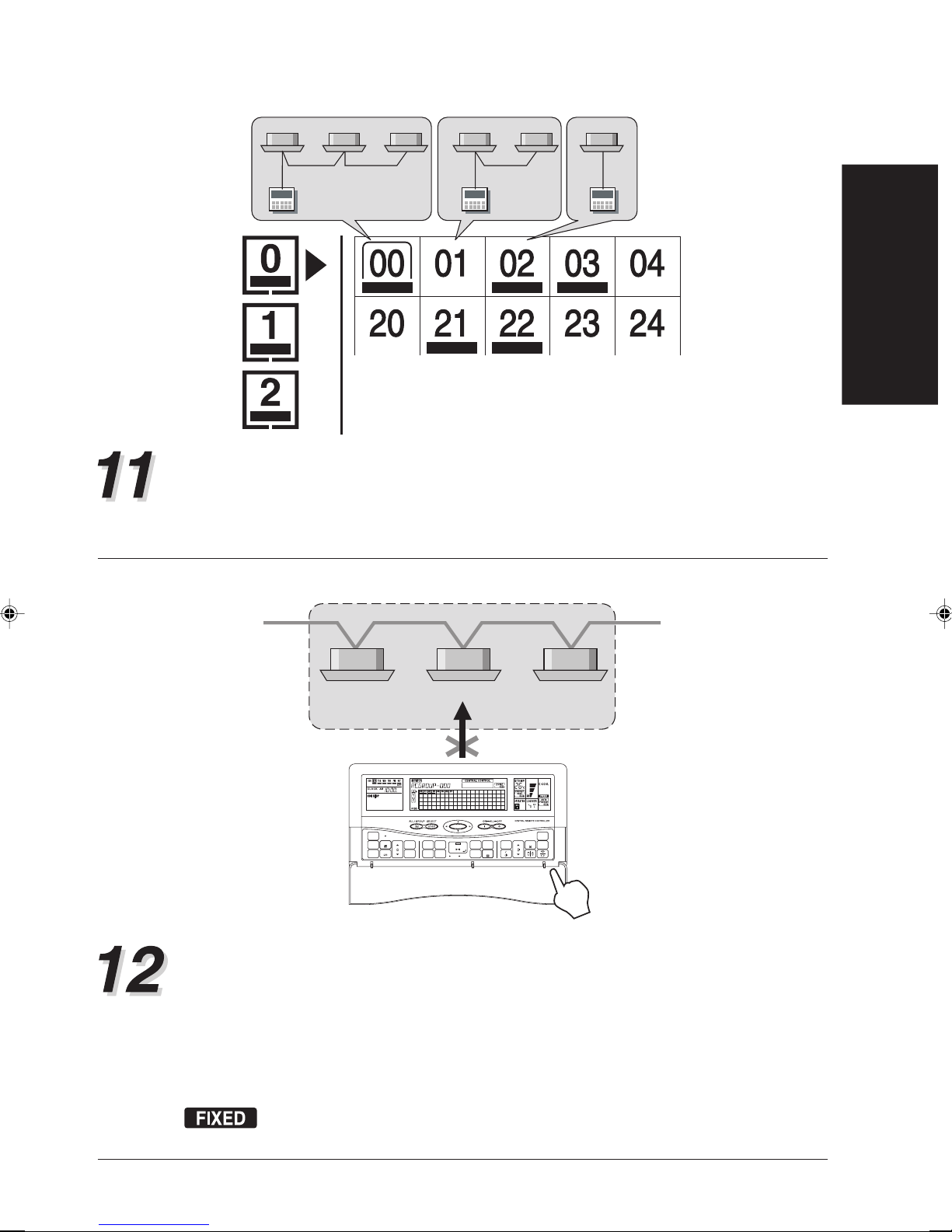
One central control number indicates
one remote control number.
Central control number (0~339):
These are the numbers by which the control of the indoor units is performed.
Each number that appears on the LCD of the central remote controller is the number that
has been assigned individually to a remote control group to be controlled and has been
stored in the central remote controller. Refer to the SETTING MANUAL for specific details.
Heating priority setting
2. SYSTEM OUTLINE
HEAT
[FIXED]
ACL
CLOCK
ADJUST
DAY
TIME
TIMER
MODE
TIMER
DAY OFF
COPY
HEAT
[FIXED]
MEMORY
CENTRAL
TIMER
CONTROL
OPERATION
DELETE
TIMER
MEMORY
GROUP
SETTING SETTING
SET
CHECK
ENERGY ANTI
BACK
ZONE
SET
SAVE
FILTER
ON OFF
RESET
DELETE
TEST
HEAT
[FIXED]
MASTER
CONTROL
FAN
TEMP.
CONTROL
FREEZE
Cooling operation
Cooling / Heating priority:
When a HEAT PUMP TYPE operating system is used, the system can only be performed
in one of two operation modes (cooling / heating) for single refrigerant system. When an
indoor unit in the system first starts an heating operation, the system is then in “heating
priority”. This means the system will refuse a command for changing the operation mode.
On the other hand, when an indoor unit in the system first starts a cooling operation, the
system is then in “cooling priority”. The system will refuse to change to any other operation
mode, except for the drying operation.
will appear on the LCD when the indoor units associated with the selected
central control number exists in cooling / heat pump type refrigerant system.
9
Page 11
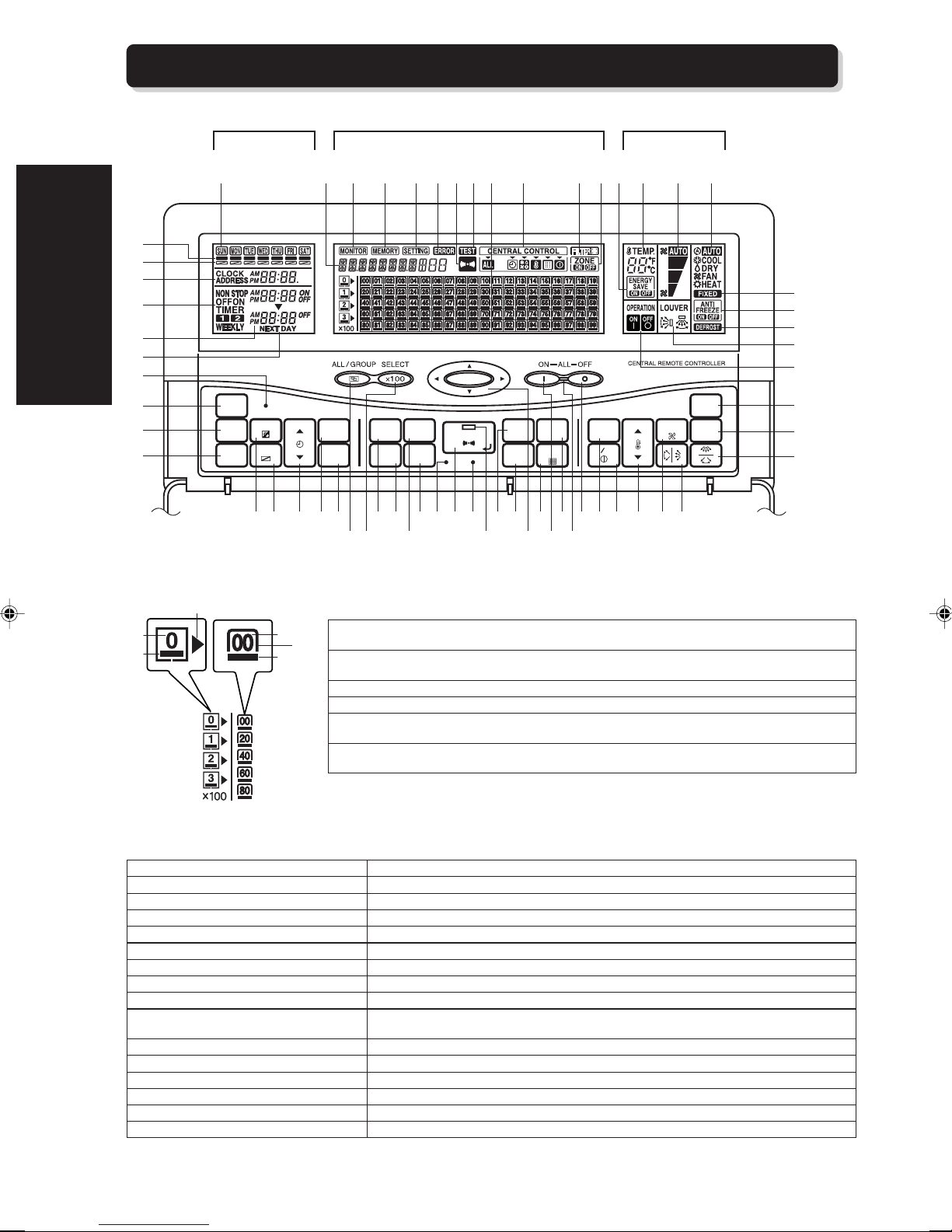
2-4. NAMES AND FUNCTIONS OF THE PARTS
TIMER CONTROL
AREA
2. SYSTEM OUTLINE
2
3
4
5
6
7
8
9
0
CLOCK
ADJUST
TIMER
MODE
TIMER
COPY
ACL
DAY
DAY OFF
OPERATION
CENTRAL CONTROL AREA
GAH1 I J K MN O P g h i
TIMER
DELETE
TIMER
SET
MEMORY
OPERATION
MEMORY
SETTING
CENTRAL
CONTROL
GROUP
SETTING
CHECK
SET
TEST
BACK
DELETE
ZONE
FILTER
RESET
c]ZYWUTFDCB E X \ r
a
CONTROL AREA
fQL
TEMP.TIME
ENERGY
SAVE
ON OFF
qpoe
FAN
CONTROL
s
MASTER
CONTROL
ANTI
FREEZE
db^[VRS
j
k
l
m
n
t
u
v
{
|
z
w
y
CENTRAL CONTROL NUMBER
w Visible numbers represent the central control numbers that have been stored. An error will
x
x Cursor: To be used in order to select the central control number. It flashes when the filter need
y Visible under lines distinguish the operating indoor units from all indoor units.
z Page cursor: To show the current page.
{ Visible page numbers inform that there are some central control numbers in the page. An error
| Visible under lines inform that at least one indoor unit which is stored in this page is now
TIMER CONTROL AREA
1 DAY OF THE WEEK DISPLAY
2 WEEKLY TIMER STATUS DISPLAY
3 DAY OFF DISPLAY
4 CLOCK AND ADDRESS DISPLAY
5 TIMER MODE DISPLAY
6 ON/OFF TIME DISPLAY
7 NEXT DAY DISPLAY
8 ALL CLEAR BUTTON
9 CLOCK ADJUST BUTTON
0 TIMER MODE BUTTON
A TIMER COPY BUTTON
B DAY BUTTON
C DAY OFF BUTTON
D TIME BUTTON
E TIMER DELETE BUTTON
F TIMER SET BUTTON
cause the relevant central control number to flash.
to be cleaned or exchanged.
will cause the relevant page number to flash.
operating.
Displays the day of the week.
Appears when the weekly timer has been set for the day.
Appears when the set weekly timer is temporarily cancelled for the day.
Shows the current time and address.
Shows the selected timer mode.
Shows the ON/OFF time to be or have be set.
Appears when the set OFF time exists in the subsequent day.
To delete all set value in the central remote controller.
To set the time.
To enter the control mode and to change the timer mode (WEEKLY TIMER / NON STOP /
OFF TIMER / ON TIMER).
To copy one day’s weekly timer settings and paste them to another day.
To change the day.
To temporarily cancel the weekly timer setting (Day off function) for a special day.
To set ON/OFF time.
To cancel the set time.
To confirm and save the time setting.
10
Page 12
CENTRAL CONTROL AREA
G STATUS DISPLAY
H MONITOR DISPLAY
I MEMORY DISPLAY
J SETTING DISPLAY
K ERROR DISPLAY
L TRANSMIT INDICATOR DISPLAY
M TEST DISPLAY
N GROUP CONTROL DISPLAY
O CENTRAL CONTROL DISPLAY
P FILTER RESET DISPLAY
Q ZONE DISPLAY
R ALL / GROUP BUTTON
S SELECT ×100 BUTTON
T MEMORY BUTTON
U MEMORY SETTING BUTTON
V CENTRAL CONTROL BUTTON
W GROUP SETTING BUTTON
X CHECK BUTTON
Y SET BUTTON
Z TEST BUTTON
[ SET LED
\ BACK BUTTON
] DELETE BUTTON
^ SELECT BUTTON
a FILTER BUTTON
b ALL ON BUTTON
c ZONE BUTTON
d ALL ON / OFF LED
e ALL OFF BUTTON
Displays the various kinds of information.
Comes on together with an individual status display.
Comes on during memory operation and setting for memory operation.
Comes on during various setting.
Comes on or flashes when error is detected.
Flashes in the period of sending the new setting from the central remote controller to other
units.
Comes on during test operation.
Displays the stored central control number and the operating status of the currently
selected indoor units.
Comes on when the functions of the standard remote controller have been prohibited by the
central remote controller.
Flashes when the filter of the selected indoor units need to be cleaned or exchanged (The
relevant DIP switches in the indoor units and in the central remote controller need to be set
firstly.).
When zone operation is conducted, zone on comes on, otherwise zone off comes on.
To change the control mode (individual / group / all).
To switch to the next screen of the central control numbers by 100.
To operate the memorized condition.
To conduct memory operation setting.
To fully or partially prohibit the setting from the selected standard remote controllers.
To start the group setting.
To switch to error code display.
To confirm the new setting and to send signals to the indoor units whose settings need to
be changed.
To start test operation.
Lights up when the new setting has been made. It will go out when the newly set
information has been sent to the relevant indoor units.
To cancel the just made setting and to return to the previous screen.
To delete the set item.
To select the central control number in central control display.
To reset the flashing filter indicator after exchanging and cleaning the filter.
To start the operation of all indoor units stored in the central remote controller.
To start and stop zone operation.
Flashes when error occurs. It will light up when an indoor unit is operating.
To stop the operation of all indoor units stored in the central remote controller.
2. SYSTEM OUTLINE
OPERATION CONTROL AREA
f ENERGY SAVE DISPLAY
g TEMPERATURE DISPLAY
h FAN CONTROL DISPLAY
i MASTER CONTROL DISPLAY
j FIXED COOLING OR HEATING
DISPLAY
k ANTI FREEZE DISPLAY
l DEFROST DISPLAY
m AIRFLOW DIRECTION DISPLAY
n ON / OFF DISPLAY
o ENERGY SAVE BUTTON
p ON / OFF BUTTON
q TEMP. BUTTON
r FAN CONTROL BUTTON
s HORIZONTAL AIRFLOW DIRECTION
AND SWING BUTTON
t MASTER CONTROL BUTTON
u ANTI FREEZE BUTTON
v VERTICAL AIRFLOW DIRECTION AND
SWING BUTTON
When energy save operation is conducted. ENERGY SAVE ON comes on, otherwise
ENERGY SAVE OFF comes on.
Shows the set temperature.
Shows the set fan speed.
Shows the current operating mode.
Comes on when the indoor unit is set in the cooling and heat pump type refrigerant system.
When the anti freeze operation is conducted. Anti freeze ON comes on. Otherwise Anti
freeze OFF comes on.
Appears when the refrigerant system of the selected indoor unit is carrying out a defrost
operation.
Shows the method to control the airflow direction.
Shows the operating condition (ON / OFF) of the indoor units associated with the selected
central control number.
To start or stop the energy save operation which is a method to keep energy consumption
cost down by controlling the thermostat temperature setting.
To turn the selected indoor units on and off.
To set room temperature.
To change the fan speed.
To set the angle or movement of up / down swing of the flaps.
To change the operating mode.
To start and stop anti freeze operation.
To set the angle or movement of right / left swing of the flaps.
11
Page 13
3. BASIC OPERATION
The following shows the two major screens of the display of the central remote controller.
3. BASIC OPERATION
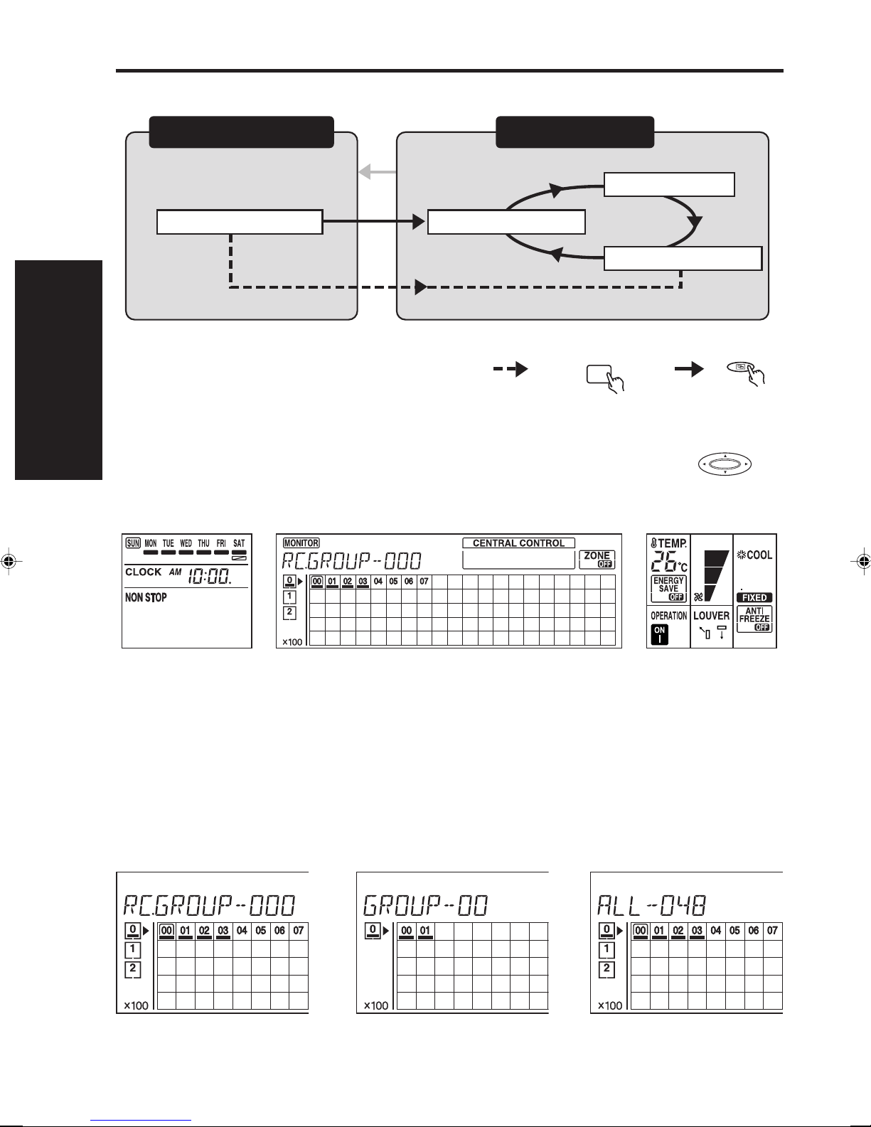
Operation display mode Control mode
Status display mode Group control mode
After
1 minute
All control mode
Individual control mode
Any one of the setting button ALL / GROUP
• Operation display mode (monitor screen)
The operating condition of each remote control group that has been stored in the central remote
controller is displayed. When a central control number is selected with the button , the
current operating condition of the relevant indoor units is shown on the LCD.
If no action is taken, this mode will be shown.
• Control mode (Setting screen)
Control mode is used to set the items to be controlled to the remote control groups that has been
stored in the central remote controller. There are three control modes in the central remote controller.
Individual control mode: Used for setting items to be controlled to a single remote control
group.
Group control mode: Used for setting items to be controlled to a grouped remote control
group.
All control mode: Used for setting items to be controlled to all of the remote control
group.
Individual control mode Group control mode All control mode
12
Page 14

Notes • If no action is taken within one minute, the screen will always returns to operation display mode automati-
cally.
• In the control mode, use to change to each of the control modes.
3. BASIC OPERATION
13
Page 15
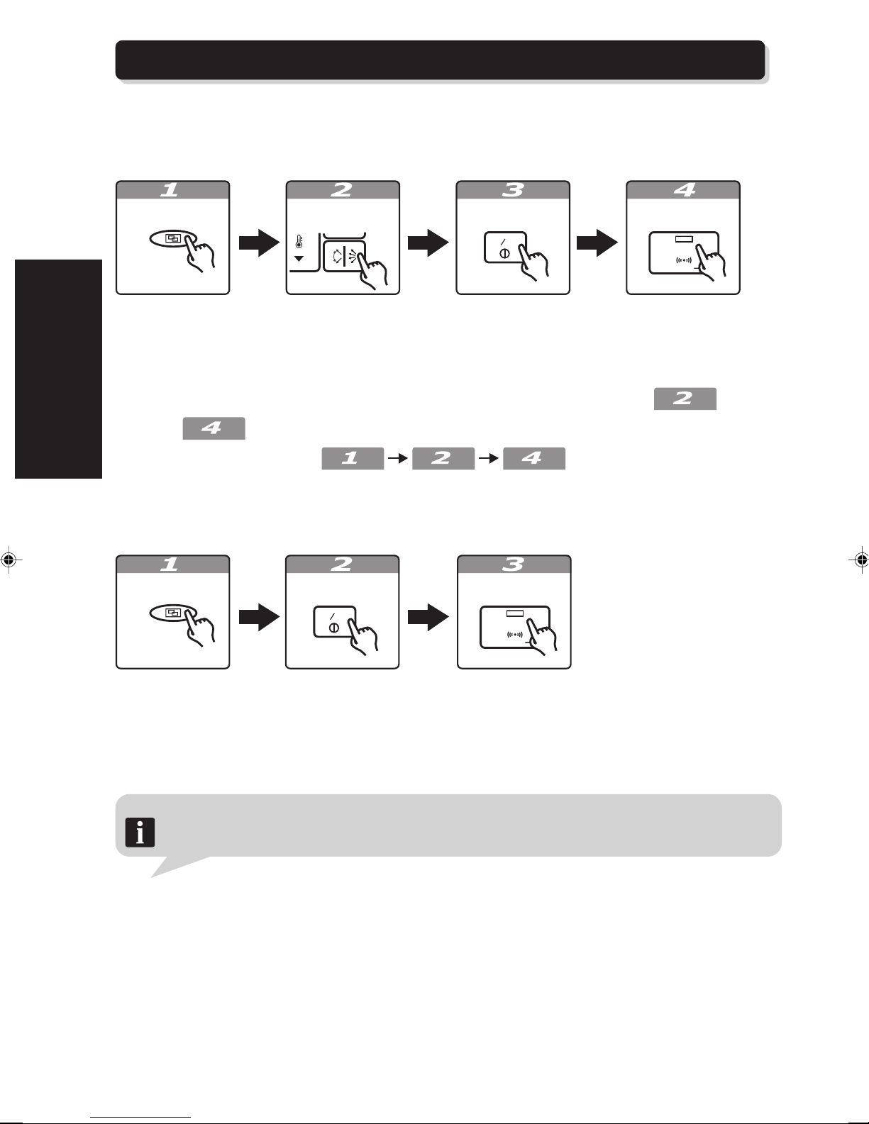
3-1. BASIC FLOW OF OPERATION
OFF
OFF
This section explains the basic flow of operation.
■ To start operation
3. BASIC OPERATION
ALL / GROUP
Select the
control mode.
Each setting button ON / OFF SET
ONONOFF
Change each of
the settings.
Set the power
supply to on
setting.
Transmit, the
newly set
information.
SET
* When several control items need to be changed, complete all the changes in and then
send in .
* Use the following sequence to make changes without start-
ing the unit.
■ To stop the operation
ALL / GROUP
ON / OFF
ONONOFF
SET
SET
Select the
control mode.
Set the power
supply to off
setting.
Notes • All the indoor units can be turned on / off at the same time with this central remote controller. For details,
refer to “5-1. ALL OPERATION/ALL STOP.”
• Please refer to sections 4, 5, 6 for details about specific operations.
14
Transmit, the
newly set
information.
Page 16
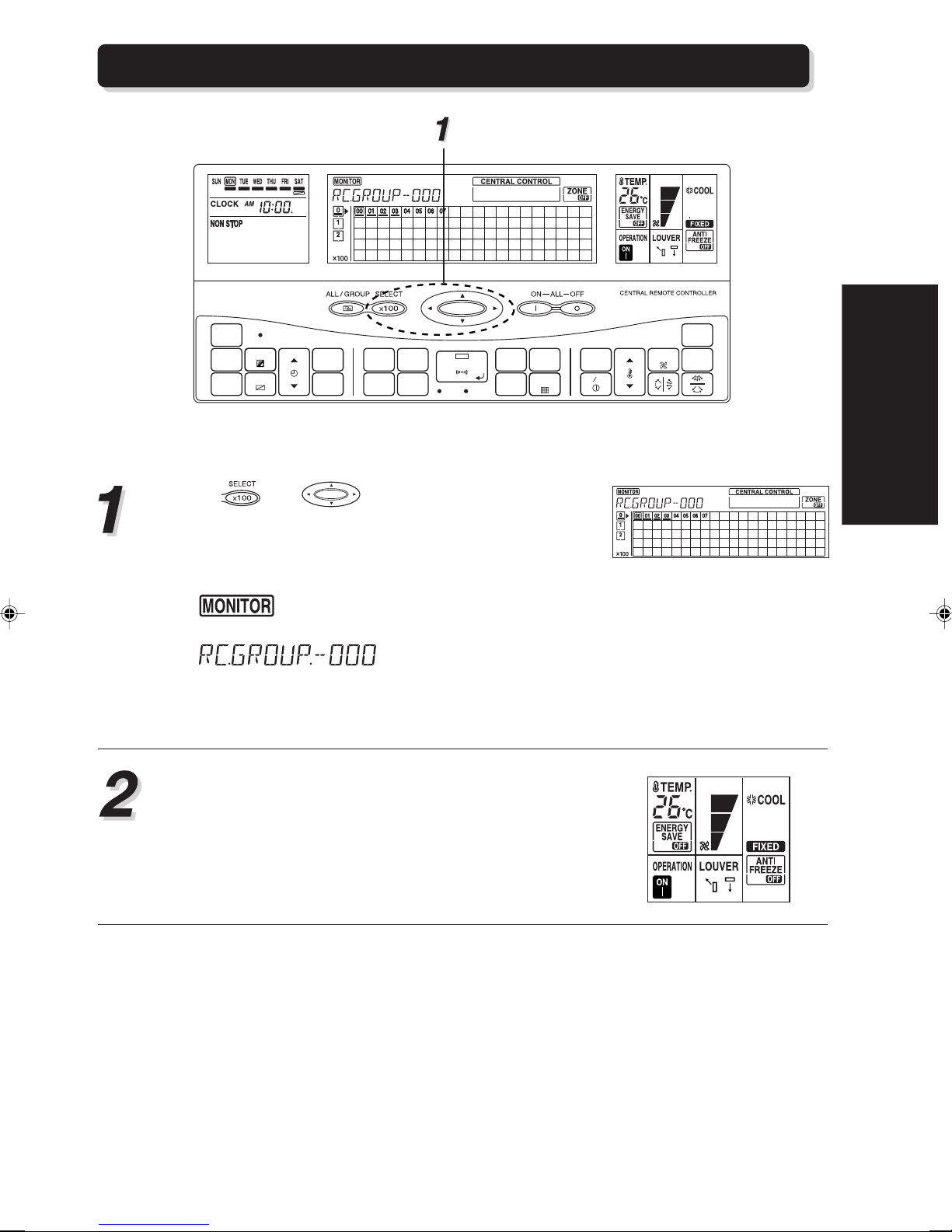
3-2. OPERATION DISPLAY MODE
ACL
CLOCK
ADJUST
DAY
DAY OFF
TIME
TIMER
DELETE
TIMER
SET
MEMORY
CENTRAL
CONTROL
OPERATION
MEMORY
GROUP
SETTING SETTING
CHECK
SET
TEST
BACK
DELETE
TIMER
MODE
TIMER
COPY
Use and to select the desired control
number.
The cursor over the central control number tells you
the central control number being selected.
ZONE
FILTER
RESET
MASTER
CONTROL
FAN
TEMP.
ENERGY ANTI
SAVE
ON OFF
CONTROL
FREEZE
3. BASIC OPERATION
• comes on in the individual operation display.
• is displayed in the status
display. The currently selected central control num-
ber is displayed. (In this example, the selected
control number is 00.)
The operation display of the remote control group
associated with the selected central control number is obtained.
15
Page 17
3. BASIC OPERATION
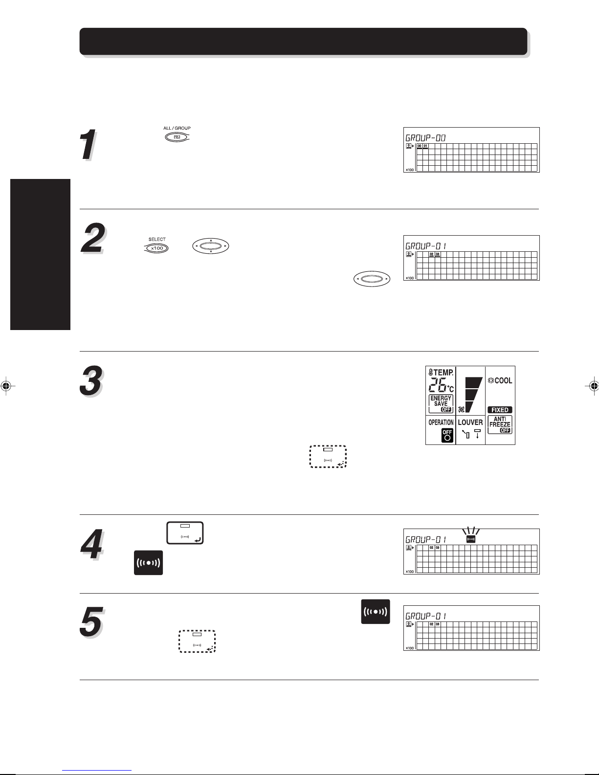
3-3. CONTROL MODE
The control of remote control groups is provided by setting the relevant items in control mode. The
following procedure for the setting is the same for any of the control modes (Individual control
mode / Group control mode / All control mode).
Push to select control mode from among In-
dividual control mode / Group control mode / All control mode.
If you wish to change the setting of the remote control group currently displayed in the operation display mode, it can be started from step 3.
• When Individual control mode is selected, use
and to select the desired central con-
trol number, then go to step 3.
• When Group control mode is selected, use
to select the desired group number, then go to step
3.
• When All control mode is selected, go directly to
step 3.
Press the buttons to change the items of setting.
Refer to “2-4. NAMES AND FUNCTIONS OF THE
PART S” for information about the buttons.
The newly set operation conditions will be applied
to the indoor units associated with the central control numbers selected in step 2.
If there is a change on setting, LED
SET
will light
up to indicate that new information about the settings needs to be sent to the relevant indoor units.
Press
SET
to send the signal to the indoor unit.
will flash during transmission.
When the signal transmission is completed,
and LED
SET
will go out. The indoor unit will start
to operate under newly set condition immediately.
16
Page 18

Individual control mode
Group control mode
• To be used to change the settings of a single
remote control group.
• To be used to change the settings of remote
controller groups in group control unit.
• Only the central control numbers (the indoor
units) that have been stored in the group appear on the LCD, when the group is selected.
• When the central control numbers that have
been stored in the group are not all included in
that one page of LCD, the relevant page number will also come on when the group is selected.
• If groups are composed of indoor units of HEAT
PUMP TYPE refrigerant system, will
appear on the LCD.
3. BASIC OPERATION
• To be used to change the settings of all remote
control groups that have been stored in the central remote controller.
All control mode
Notes • In order to shorten the setting time as well as to simplify the setting procedure, it is possible to send all of
the set information by pressing
FLOW OF OPERATION”.)
• The time between each press of the buttons should be less than 1 minute, otherwise, after five time of
Beep sound. (in 30 seconds) all the changes that have been made will disappear.
SET
after all the changes have be made. (Refer to “3-1. BASIC
17
Page 19
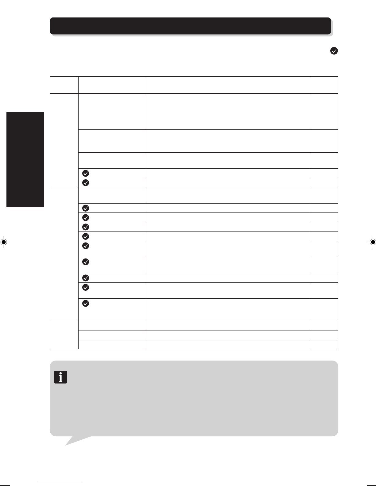
3-4. FUNCTION LIST
The following show the function list of the central remote controller. The functions shown with a
can be set following the procedures shown in “3-1. BASIC FLOW OF OPERATION”. Refer to each of
the items for more detail information.
3. BASIC OPERATION
FUNCTION
CENTRAL CONTROL
OPERATION CONTROL FUNCTION
TIMER
CONTROL
FUNCTION
Function Description of the function
Group information store Form a control unit - “group” which is combined by remote control
groups (indoor units) so that the indoor units in the same group can
be controlled simultaneously.
Standard remote controller operation prohibition setting:
Restrict the setting items of a standard remote controller.
Standard remote Sets the operating limit for the standard remote control for the
controller operation assigned indoor unit.
prohibit setting
Memory operation Save the current operating conditions. The saved operating
conditions can be reproduced at any time easily.
Zone setting Perform zone operation. P28
Filter indicator reset Reset the filter indicator after cleaned or exchanged the filter. P30
All operation / All stop Operate or stop all the indoor units that have been stored to the
central remote controller.
Operation / Stop Operate / Stop the selected indoor units. P33
Operating mode setting Perform the operating mode setting of the selected indoor units. P35
Temperature setting Perform the room temperature setting of the selected indoor units. P38
Fan speed setting Perform the fan speed setting of the selected indoor units. P39
Flow direction setting
(vertical)
Flow direction setting
(horizontal)
Swing setting Perform auto-swing operation in vertical or in horizontal direction. P46
Energy save Perform the energy save operation in order to operate the system
operation setting economically.
Anti freeze operation Automatically start a heating operation to prevent the room
OFF timer Stop the indoor units at the set time. P56
ON timer Start the indoor units at the set time. P58
Weekly timer Up to two on / off settings for each day of the week. P60
Adjust the vertical angle of the flaps of the selected indoor units. P41
Adjust the horizontal angle of the flaps of the selected indoor units. P44
temperature from becoming too low and stop when the
temperature rises above a preset level.
Reference
page
P20
P23
P26
P32
P50
P53
Notes Beep sound:
The BEEP sound has the following meanings.
• “Beep”
This is the beep sound made when a button is operated.
• “Beep Be”
This is the beep sound when the transmission has been completed in the control mode.
• “Beep Beep Beep Beep Beep”
This is the beep sound when there has been an operating error.
• “Beep-Beep, Beep-Beep, Beep-Beep, ···”
This is the beep sound when you forget to press the transmit key when in the control mode.
18
Page 20
4. CENTRAL CONTROL
METHOD (CENTRAL
CONTROL AREA)
This section explains the methods on group information store, on how to place the restrictions on the
standard remote controllers, as well as the control
items on management of the indoor units using the
setting buttons in central control area of the central
remote controller.
4-1. GROUP INFORMATION
STORE ...................................... 20
4-2. STANDARD REMOTE
CONTROL OPERATION
PROHIBIT SETTING ................. 23
4-3. MEMORY OPERATION............. 26
4-4. ZONE SETTING........................ 28
4-5. FILTER INDICATOR RESET ..... 30
CONTROL METHOD
4. CENTRAL
Page 21
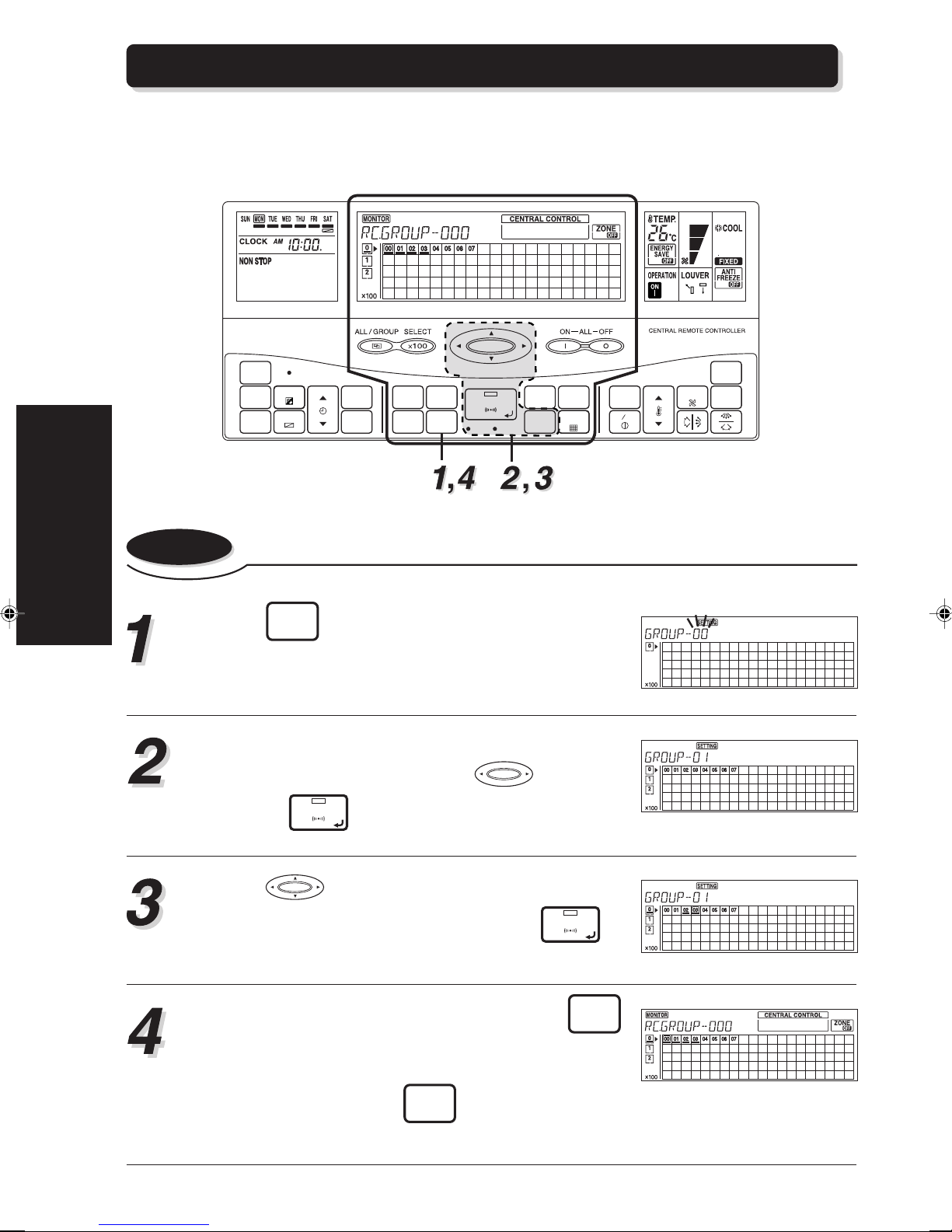
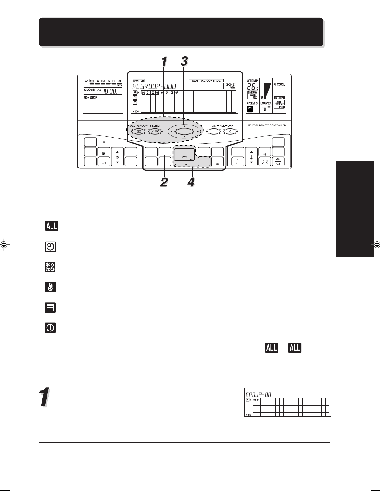
4-1. GROUP INFORMATION STORE
It is necessary to do group information store before group control is conducted with the central
remote controller.
The following shows the procedure of group information store.
4. CENTRAL
CONTROL METHOD
CLOCK
ADJUST
TIMER
MODE
TIMER
COPY
ACL
DAY
DAY OFF
TIME
TIMER
DELETE
TIMER
SET
MEMORY
CENTRAL
CONTROL
OPERATION
MEMORY
GROUP
SETTING SETTING
CHECK
SET
TEST
BACK
DELETE
ZONE
FILTER
RESET
MASTER
CONTROL
FAN
TEMP.
ENERGY ANTI
SAVE
ON OFF
CONTROL
FREEZE
4-1-1. To do group information store
Press
mode.
Select the group number whose group information
store need to be performed with and set by
pressing
Press to select the central control number
to be stored in the selected group. Press
store.
GROUP
to enter the group information store
SETTING
SET
.
SET
to
To continue group information store, press
to return to the group number selection screen of 1
and repeat steps 2 and 3. To complete the group in-
formation store, press
tion screen shown in step 1.
20
GROUP
in the group selec-
SETTING
BACK
Page 22
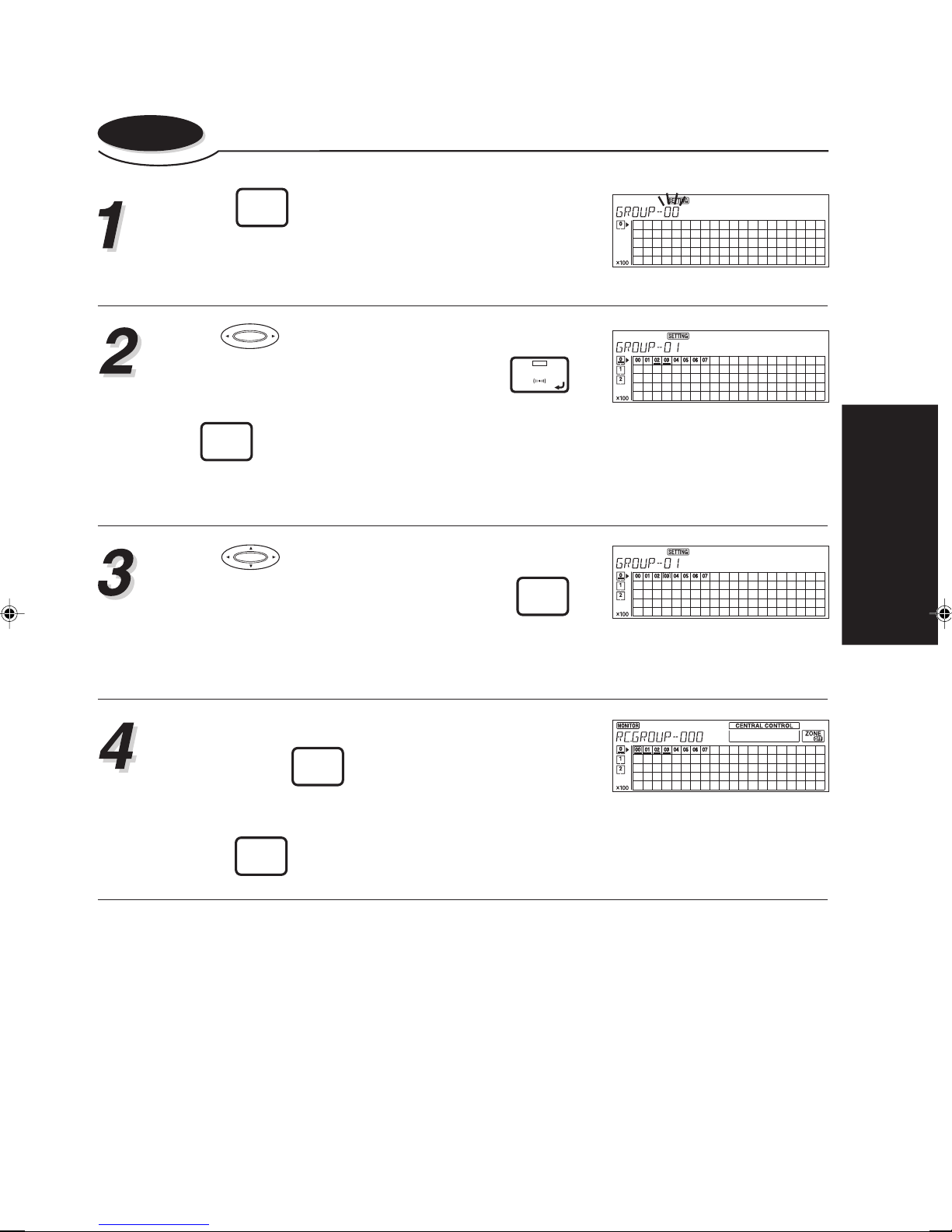
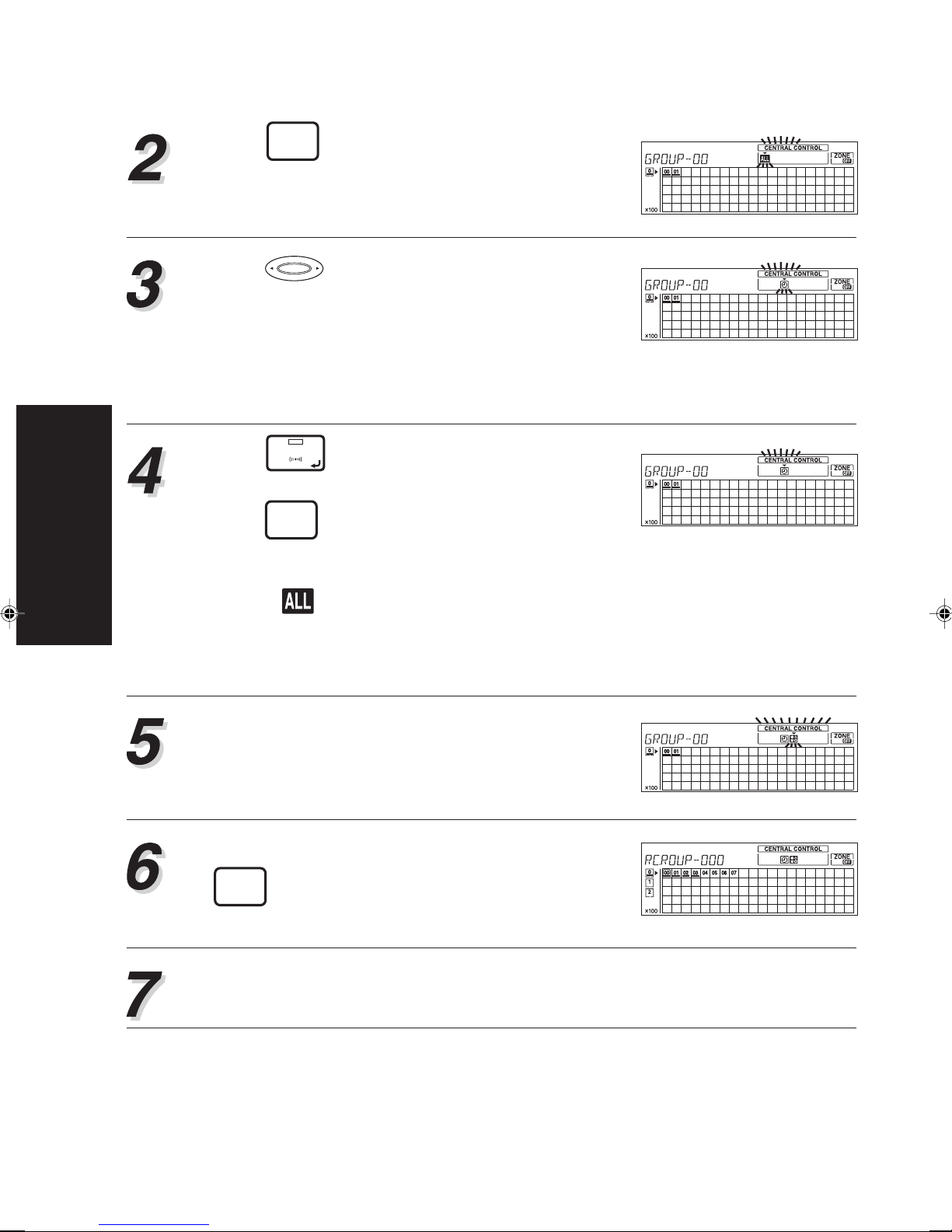
4-1-2. To delete the stored information in group
Press
GROUP
to enter the group information store.
SETTING
Use to select the group whose stored infor-
mation is to be deleted and then press
SET
to
set it.
DELETE
If
is pressed at this time, all the central con-
trol numbers registered in the selected group will
be deleted.
Use to select the central control number in
the group selected in step 2 and press
DELETE
to
delete it.
Repeat step 3 to continue deleting the stored central control number in the same group.
CONTROL METHOD
4. CENTRAL
If you wish to delete the stored information in other
group, press
BACK
to return to screen of step 1.
Repeat steps 2 and 3.
To end the deletion of the stored group information,
press
GROUP
SETTING
.
21
Page 23
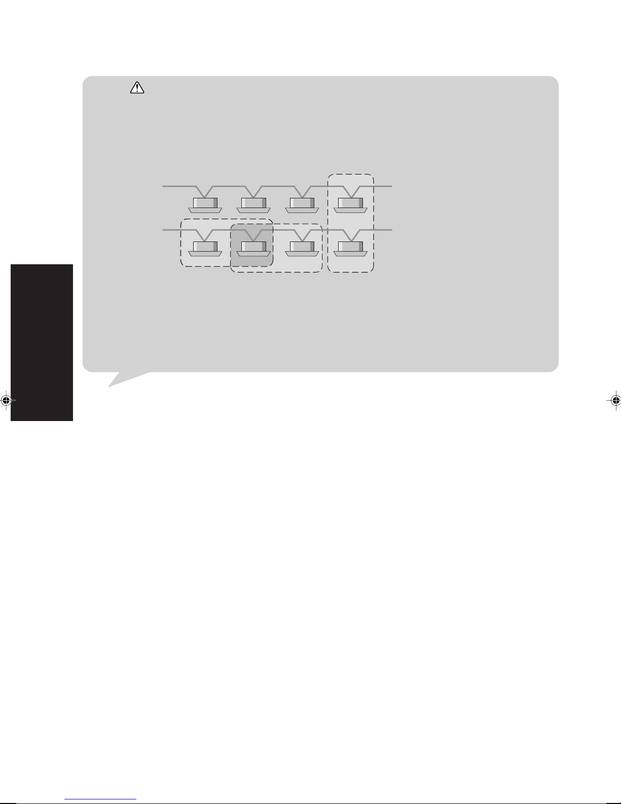
Notes Group Information Store
4. CENTRAL
CONTROL METHOD
The following show the restrictions on group information store.
• A maximum of 64 groups can be formed in one system.
• A maximum of 64 remote control groups can be stored per group.
• Since the remote control group is the smallest control unit and can not be broken up, the group
must be made up with complete remote control groups.
The following show examples of group formation. There are some restrictions on operating mode, on
display for the following occasions.
Refrigerant system 1
Refrigerant system 2
• Group formed with the indoor units in two refrigerant systems.
When part of indoor units exist in cooling & heat pump type refrigerant system, certain operating
mode of the group can not be carried out even if the operating mode is shown on the LCD. In
addition, the operating mode is limited owing to cooling / heating priority setting.
• Overlapping groups.
The operating condition of the indoor units overlapped in the group is determined by the control
signal last sent to indoor units.
22
Page 24
4-2. STANDARD REMOTE CONTROL OPERATION
PROHIBIT SETTING
ACL
CLOCK
ADJUST
TIMER
MODE
TIMER
COPY
DAY
DAY OFF
TIME
TIMER
DELETE
TIMER
SET
MEMORY
CENTRAL
CONTROL
OPERATION
MEMORY
GROUP
SETTING SETTING
CHECK
SET
TEST
BACK
DELETE
ZONE
FILTER
RESET
TEMP.
ENERGY ANTI
SAVE
ON OFF
In validate (or do not able to make) the operation settings from the relevant standard remote controller by pressing the central remote controller. The following shows the centrally controlling items that
can be performed.
FAN
CONTROL
MASTER
CONTROL
FREEZE
• ......... Invalidate (or do not able to make) all operation settings from the relevant standard
remote controllers.
• .......... Invalidate (or do not able to make) all timer settings (OFF / ON / WEEKLY) from the
relevant standard remote controller.
• .......... Invalidate (or do not able to make) mode operation setting from the relevant standard
remote controller.
• .......... Invalidate (or do not able to make) temperature setting from the relevant standard
remote controller.
• .......... Invalidate (or do not able to make) filter reset operation from the relevant standard
remote controller.
• .......... Invalidate (or do not able to make) ON / OFF operation of the indoor units from the
relevant standard remote controller.
Several of the centrally controlling items can be set simultaneously, except . If is set, all
operation settings of the relevant standard remote controller invalidate (wireless) or cannot be made
(wired). The started centrally controlling items can be set only when DIP-SW 2-5 “enable / disable
setting of the standard remote controller prohibition function” has been set to enable.
Enter the control mode to select the central control
number (the indoor units), so that the relevant standard remote controllers whose centrally controlling
items need to be set are also selected.
Refer to “3-3. CONTROL MODE” for details about
control modes.
CONTROL METHOD
4. CENTRAL
23
Page 25
4. CENTRAL
CONTROL METHOD
Press
CENTRAL
CONTROL
to start setting of the centrally con-
trolling items.
An item selection cursor will appear.
Press and use the cursor to select the cen-
trally controlling items to be performed.
A symbol will come on for the item that are being
set.
• Symbols will go out for those items that are not
being set. When it becomes aligned with the cursor, it will start to flash.
Press
SET
to set the centrally controlling item
to be performed.
Press
DELETE
to cancel the item.
• The symbol comes on after the setting of the centrally controlling item.
• Select and all those other symbols will go out
because this centrally controlling item includes all
those other controlling items by prohibiting all
operation settings of standard remote controller.
Repeat the operations of step 3 and step 4 to perform the desired central control.
When all the settings have been completed, press
CENTRAL
CONTROL
to end up the centrally controlling settings
of the standard remote controllers.
It is necessary to transmit the newly set information to the relevant indoor units.
Refer to steps 4, 5 and notes of “3-3. CONTROL MODE” for details.
24
Page 26

Notes When several of central remote controllers have been connected in one system, the centrally controlling
items, can be set or removed by using any central remote controller in the system. If the set centrally
controlling items are not hoped to be removed by setting other central remote controllers, please set the
DIP-SW 2-5 “enable / disable setting of the standard remote controller prohibition function” to disable
position. (It is recommended that only the host central remote controller should be set to enable and the
others should be set to disable.)
CONTROL METHOD
4. CENTRAL
25
Page 27

4-3. MEMORY OPERATION
The memory operation can reproduce the operating conditions, which have been saved beforehand, by only one touch of MEMORY SETTING button.
4-3-1. Memory operation settings
Before operating a memory operation, the memory operation setting must be performed so that the
operating conditions will be prepared in a memory.
4. CENTRAL
CONTROL METHOD
CLOCK
ADJUST
TIMER
MODE
TIMER
COPY
ACL
DAY
DAY OFF
TIME
TIMER
DELETE
TIMER
SET
MEMORY
CENTRAL
CONTROL
OPERATION
MEMORY
GROUP
SETTING SETTING
CHECK
SET
TEST
BACK
DELETE
ZONE
FILTER
RESET
MASTER
CONTROL
FAN
TEMP.
ENERGY ANTI
SAVE
ON OFF
CONTROL
FREEZE
Press
MEMORY
SETTING
.
will come on and the unit is in
memory operation setting mode.
• In memory operation setting mode, the contents
of the saved memory operation settings are dis-
played. Press and to check the con-
tents.
Press
SET
and the current operating conditions
are saved.
Press
MEMORY
again to end the memory operation
SETTING
setting mode.
26
Page 28

4-3-2. Memory operation
The memory operation is performed and the saved operating conditions come on to the display.
Press
After receiving the necessary data from the central
remote controller, the indoor unit starts a memory
operation.
MEMORY
OPERATION
.
CONTROL METHOD
4. CENTRAL
27
Page 29

4-4. ZONE SETTING
When the ZONE button is pressed, the actual operation condition (ON or OFF) of the selected
indoor units is determined by the set position of the DIP switch in the indoor unit.
4-4-1. To start zone operation
4. CENTRAL
CONTROL METHOD
CLOCK
ADJUST
TIMER
MODE
TIMER
COPY
ACL
DAY
DAY OFF
TIME
TIMER
DELETE
TIMER
SET
MEMORY
CENTRAL
CONTROL
OPERATION
MEMORY
GROUP
SETTING SETTING
CHECK
SET
TEST
BACK
DELETE
ZONE
FILTER
RESET
MASTER
CONTROL
FAN
TEMP.
ENERGY ANTI
SAVE
ON OFF
CONTROL
FREEZE
Enter the control mode to select the central control
group (the indoor units) whose zone operation is to
be performed.
Refer to “3-3. CONTROL MODE” for details about
control modes.
Press
ZONE
. will appear.
It is necessary to transmit the newly set information
to the relevant indoor units. Refer to steps 4, 5 and
notes of “3-3. CONTROL MODE” for details.
28
Page 30

4-4-2. To end zone operation
Enter the control mode to select the central control
group (the indoor units) whose zone operation is to
be ended.
Refer to “3-3. CONTROL MODE” for information
about control modes.
Press
ZONE
once again. will appear.
It is necessary to transmit the newly set information
to the relevant indoor units. Refer to steps 4, 5 and
notes of “3-3. CONTROL MODE” for details.
Note The zone function can be used only with the following indoor units.
A TFAMF
A TFBMF
AU TFBMF
CONTROL METHOD
4. CENTRAL
29
Page 31

4-5. FILTER INDICATOR RESET
The filter indicator flashes when the filter needs to be cleaned or exchanged.
4. CENTRAL
CONTROL METHOD
When the working time of the filter reached the set time, the indicator and cursor
associated with the indoor unit will flash in order to inform you that the filter needs to be cleaned or
exchanged.
CLOCK
ADJUST
TIMER
MODE
TIMER
COPY
ACL
DAY
DAY OFF
TIME
TIMER
DELETE
TIMER
SET
MEMORY
CENTRAL
CONTROL
OPERATION
MEMORY
GROUP
SETTING SETTING
CHECK
SET
TEST
BACK
DELETE
ZONE
FILTER
RESET
MASTER
CONTROL
FAN
TEMP.
ENERGY ANTI
SAVE
ON OFF
CONTROL
FREEZE
• Operation display mode /
Individual control mode........... will flash if the filter of an indoor unit in the currently
displayed remote control group needs to be cleaned or
exchanged.
• Group control mode ................. will flash if the filter of any indoor unit in the group
currently displayed needs to be cleaned or exchanged.
• All control mode....................... will flash if the filter of any indoor unit in the system
needs to be cleaned or exchanged.
After the filter has been cleaned, or exchanged please reset the filter indicator by:
FILTER
Press
RESET
.
will stop flashing and LED
SET
will
light up.
Press
SET
to send the filter reset signal to se-
lected indoor units, when the signal transmission.
Transmission is made. and will go out.
Note Since there is a need to enable the filter indicator function, please consult your sales representative.
30
Page 32

5. OPERATION SETTING
METHOD (OPERATION
CONTROL AREA)
This section explains the methods on operation setting using the buttons in operation control area of
the central remote controller.
5-1. ALL OPERATION /
ALL STOP ................................ 32
5-2. OPERATION / STOP ................ 33
5-3. OPERATING MODE
SETTING .................................. 35
5-4. TEMPERATURE SETTING ...... 38
5-5. FAN SPEED SETTING ............ 39
5-6. FLOW DIRECTION SETTING
(VERTICAL).............................. 41
5-7. FLOW DIRECTION SETTING
(HORIZONTAL) ........................ 44
5-8. SWING SETTING ..................... 46
5-9. ENERGY SAVE OPERATION
SETTING .................................. 50
5-10.ANTI FREEZE OPERATION .... 53
SETTING METHOD
5. OPERATION
Page 33

5-1. ALL OPERATION / ALL STOP
ACL
CLOCK
ADJUST
DAY
DAY OFF
TIME
TIMER
DELETE
TIMER
SET
MEMORY
CENTRAL
CONTROL
OPERATION
MEMORY
GROUP
SETTING SETTING
CHECK
SET
TEST
BACK
DELETE
FILTER
RESET
TIMER
MODE
TIMER
COPY
5-1-1. All operation
ZONE
MASTER
CONTROL
FAN
TEMP.
ENERGY ANTI
SAVE
ON OFF
CONTROL
FREEZE
5. OPERATION
SETTING METHOD
Press . will light up. An all opera-
tion signal will be transmitted in the system immediately.
A beep sound “Beep Be” signals the end of the transmission.
When the transmission has been completed,
and will go out.
5-1-2. All stop
Press . will light up. An all stop
signal will be transmitted in the system immediately.
A beep sound “Beep Be” signals the end of the transmission.
When the transmission has been completed,
and will go out.
32
Page 34

5-2. OPERATION / STOP
5-2-1. To start operation
ACL
CLOCK
ADJUST
DAY
DAY OFF
TIME
TIMER
DELETE
TIMER
SET
MEMORY
CENTRAL
CONTROL
OPERATION
MEMORY
GROUP
SETTING SETTING
TIMER
MODE
TIMER
COPY
CHECK
SET
TEST
BACK
DELETE
ZONE
FILTER
RESET
MASTER
CONTROL
FAN
TEMP.
ENERGY ANTI
SAVE
ON OFF
CONTROL
FREEZE
LOUVERLOUVER
Enter the control mode to select the central control
number (the indoor units) to start its operation.
Refer to “3-3. CONTROL MODE” for information
about control modes.
Press
ON OFF
and will light up. The setting is
applied to the indoor units associated with the selected central control number. Because of the
change of the setting, LED
SET
will come on.
It is necessary to transmit the newly set information
to the relevant indoor units. Refer to steps 4, 5 and
notes of “3-3. CONTROL MODE” for details.
SETTING METHOD
5. OPERATION
33
Page 35

5-2-2. To stop operation
Enter the control mode to select the central control
number (the indoor units) to stop its operation.
Refer to “3-3. CONTROL MODE” for information
about control modes.
Press
applied to the indoor units associated with the selected central control number. Because of the
change of the setting, LED
It is necessary to transmit the newly set information
to the relevant indoor units. Refer to steps 4, 5 and
5. OPERATION
notes of “3-3. CONTROL MODE” for details.
SETTING METHOD
ON OFF
and will light up. The setting is
SET
will come on.
34
Page 36

5-3. OPERATING MODE SETTING
ACL
CLOCK
ADJUST
DAY
DAY OFF
TIME
TIMER
DELETE
TIMER
SET
MEMORY
CENTRAL
CONTROL
OPERATION
MEMORY
GROUP
SETTING SETTING
CHECK
SET
TEST
BACK
DELETE
ZONE
FILTER
RESET
TIMER
MODE
TIMER
COPY
Enter the control mode to select the central control
number (the indoor units) whose operating mode
needs to be changed.
Refer to “3-3. CONTROL MODE” for information
about control modes.
MASTER
CONTROL
FAN
TEMP.
ENERGY ANTI
SAVE
ON OFF
CONTROL
FREEZE
Press
MASTER
CONTROL
to select the desired operating mode.
The setting is applied to the indoor units associated with the selected central control number. Be-
cause of the change of the setting, LED
SET
will
come on.
It is necessary to transmit the newly set information
to the relevant indoor units. Refer to steps 4, 5 and
notes of “3-3. CONTROL MODE” for details.
SETTING METHOD
5. OPERATION
35
Page 37

Notes * Cannot be set in HEAT PUMP TYPE refrigerant system.
** Cannot be set in COOLING ONLY TYPE refrigerant system.
When a group is comprised of indoor units which are in different types of refrigerant systems (HEAT
RECOVERY TYPE / HEAT PUMP TYPE / COOLING ONLY TYPE), it is still possible to do an operating
mode setting for the group. However, the newly set operating mode will be conducted only by those
remote control groups in the group, when the newly set operating mode can be conducted by them.
When a heating operation mode is attempted on a cooling only type refrigerant system, the central
control number will flash and the set operating mode will not be conducted. This occurs when a group
comprised of indoor units with different types of refrigerant systems (heat recovery type / cooling &
heat pump type / cooling only type). Actually, the operating command is sent to the relevant indoor
units, but the command will not be conducted by those indoor units when the set operating mode is not
permitted by the type of refrigerant system where they exist.
About operating modes
AUTO ..COOLING MODEL
• When the room temperature is 2 °C higher than the set temperature, the operating mode will switch between Cooling and Drying.
• During the Drying mode operation, the FAN setting should be
5. OPERATION
SETTING METHOD
switched to LOW for a gently cooling effect during which the fan
may temporarily stop rotating.
• If the mode automatically selected by the unit is not satisfactory,
see above and change the mode setting (COOL , FAN).
AUTO (AUTO CHANGE OVER) ..HEAT&COOL MODEL (Reverse cycle)
• When AUTO CHANGE OVER is selected, the air conditioner selects the appropriate operating
mode (Cooling or Heating) according to the real room temperature.
• When AUTO CHANGE OVER is first selected, the fan will operate at very low speed for about one
minutes while the unit determines the current conditions of the room and accordingly selects the
proper operation mode.
• When the air conditioner has adjusted the room temperature to near the thermostat setting, it will
being monitor operation. In the monitor operation mode, he fan will operate at low speed. If the
room temperature subsequently changes, the air conditioner will select the appropriate operation
(Heating, Cooling) once again to adjust the temperature to the value set with the thermostat. (The
monitor operation range is ±2 °C relative to the thermostat setting.)
• If the mode automatically selected by the unit is not satisfactory, see above and change the mode
setting (HEAT, COOL, FAN).
• Do not select AUTO CHANGE OVER if the difference in the environmental temperature of the
master and slave units is over 2 °C. (Otherwise, the indoor fan may not be controlled correctly.)
Cooling Operation
Dry Operation
Thermostat control
2 °C
Setting temperature
Heating
• Use to warm your room.
• When Heating mode is selected, the air conditioner will operate at very low fan speed for about 3
to 5 minutes, after which it will switch to the selected fan speed setting. This period of time is
provided to allow the indoor units to warm up before a full operation.
• When the room temperature is very low, frost may form on the outdoor unit, therefore, the performance of the outdoor unit will decrease. In order to remove such frost, the unit will automatically
enter the defrost cycle from time to time. During defrosting, the heating mode will be temporarily
interrupted will be shown on the remote controller display.
36
Page 38

Cooling
• Use to cool your room.
Fan
• Use to circulate the air throughout your room.
During Heating
The set thermostat temperature should be higher than the actual room temperature, otherwise the heating mode does not
work.
During Cooling
The set thermostat temperature should be lower than the actual room temperature, otherwise the cooling mode does not
work, however the fan will rotate in cooling mode.
SETTING METHOD
5. OPERATION
37
Page 39

5-4. TEMPERATURE SETTING
Enter the control mode to select the central control
number (the indoor units) whose temperature needs
to be changed.
5. OPERATION
SETTING METHOD
Refer to “3-3. CONTROL MODE” for information
about control modes.
CLOCK
ADJUST
TIMER
MODE
TIMER
COPY
ACL
DAY
DAY OFF
TIME
TIMER
DELETE
TIMER
SET
MEMORY
CENTRAL
CONTROL
OPERATION
MEMORY
GROUP
SETTING SETTING
CHECK
SET
TEST
BACK
DELETE
ZONE
FILTER
RESET
MASTER
CONTROL
FAN
TEMP.
ENERGY ANTI
SAVE
ON OFF
CONTROL
FREEZE
TEMP.
Press
to set the desired temperature. The set-
ting is applied to the indoor units associated with
the selected central control number. Because of the
change of the setting, LED
It is necessary to transmit the newly set information
to the relevant indoor units. Refer to steps 4, 5 and
notes of “3-3. CONTROL MODE” for details.
Notes ▲: Press to raise the thermostat setting.
▼: Press to lower the thermostat setting.
• Thermostat setting range
AUTO ................ 18 to 30 °C
Heating .............. 16 to 30 °C
Cooling / Dry ..... 18 to 30 °C
• The thermostat cannot be used to set room temperature during the FAN mode (the temperature will not
appear on the display of the central remote controller).
• The thermostat setting should be considered a standard value, and may differ somewhat from the room
temperature.
SET
will come on.
38
Page 40

5-5. FAN SPEED SETTING
ACL
CLOCK
ADJUST
DAY
DAY OFF
TIME
TIMER
DELETE
TIMER
SET
MEMORY
CENTRAL
CONTROL
OPERATION
MEMORY
GROUP
SETTING SETTING
SET
CHECK
TIMER
MODE
TIMER
COPY
Enter the control mode to select the central control
number (the indoor units) whose fan speed needs
to be changed.
Refer to “3-3. CONTROL MODE” for information
about control modes.
TEST
BACK
DELETE
ZONE
FILTER
RESET
MASTER
CONTROL
FAN
TEMP.
ENERGY ANTI
SAVE
ON OFF
CONTROL
FREEZE
FAN
Press
CONTROL
to set the desired for speed.
The setting is applied to the indoor units associated with the selected central control number. Be-
cause of the change of the setting, LED
SET
will
come on.
It is necessary to transmit the newly set information
to the relevant indoor units. Refer to steps 4, 5 and
notes of “3-3. CONTROL MODE” for details.
SETTING METHOD
5. OPERATION
39
Page 41

About the AUTO setting of fan speed
Heating: Fan operates so as to optimally circulate warmed air. However, the fan will operate at very
low speed when the temperature of the air issued from the indoor unit is low.
Cooling: As the room temperature approaches that of thermostat setting, the fan speed becomes
slower.
Fan: The fan alternately turns on and off; when the fan turns on, it rotates at a low fan speed.
• The fan will operate at a very low speed during the monitor operation by which the room temperature is deleted.
Note If fan speed setting is attempted on a cooling & heat pump type refrigerant system, the central control
5. OPERATION
SETTING METHOD
number will flash and fan operation will not be affected by the settings.
This occurs when a group is comprised of indoor units which are in different types of refrigerant
systems. (HEAT RECOVERY TYPE / HEAT PUMP TYPE / COOLING ONLY TYPE ) (Actually, the
command for the fan speed setting is sent to the relevant indoor units, it will not be conducted by those
indoor units where the fan speed setting is not permitted by the type of refrigerant system where they
exist.)
40
Page 42

5-6. FLOW DIRECTION SETTING (VERTICAL)
This instructions are applicable to “CEILING SUSPENSION TYPE”, “FLOOR CONSOLE / UNDER
CEILING DUAL TYPE”, “CASSETTE TYPE” and “WALL MOUNTED TYPE”.
ACL
CLOCK
ADJUST
TIMER
MODE
TIMER
COPY
DAY
DAY OFF
TIME
TIMER
DELETE
TIMER
SET
MEMORY
CENTRAL
CONTROL
OPERATION
MEMORY
GROUP
SETTING SETTING
CHECK
SET
TEST
BACK
DELETE
ZONE
FILTER
RESET
TEMP.
ENERGY ANTI
SAVE
ON OFF
FAN
CONTROL
MASTER
CONTROL
FREEZE
Enter the control mode to select the central control
number (the indoor units) whose vertical flow direction needs to be changed.
Refer to “3-3. CONTROL MODE” for information
about control modes.
Press to adjust the flaps angle in order to
generate a desired vertical airflow.
The setting is applied to the indoor units associated with the selected central control number. Be-
cause of the change of the setting, LED
SET
will
come on.
Each time the button is pressed, the air direction as
shown in the display will change as follows;
1
2
3
4
SETTING METHOD
5. OPERATION
41
Page 43

It is necessary to transmit the newly set information
to the relevant indoor units. Refer to steps 4, 5 and
notes of “3-3. CONTROL MODE” for details.
Notes • At the beginning the vertical airflow direction is set automatically as shown, in accordance with the type of
operation selected.
During cooling mode: Horizontal flow 1
During heating mode: Downward flow 4
• The air direction can be adjusted within the range shown below.
• During AUTO mode operation, for the first minute after beginning operation, airflow will be horizontal flow
1; the air direction cannot be adjusted during this period.
• If the direction setting is set at the same time as operation mode setting, the indoor unit will follow the flow
direction setting that has been set.
5. OPERATION
SETTING METHOD
42
Page 44

■ CEILING SUSPENSION TYPE ■ FLOOR CONSOLE/UNDER CEILING
DUAL TYPE
1
2
3
4
■ CASSETTE TYPE
1
2
3
4
1
2
3
4
■ WALL MOUNTED TYPE
Notes • Always use the remote controller’s AIR FLOW DIRECTION button to adjust the UP / DOWN air
direction louvers. Attempting to move them manually could result in improper operation; in this case,
stop operation and restart. The flaps should begin to operate properly again.
• During use of the Cooling mode, do not set the UP / DOWN air direction flap in the 4 position for a
long period of time, since water vapor may condense near the outlet port and drops of water may
drip from the air conditioner.
• When used in a room with infants, children, elderly or sick persons, the air direction and room
temperature should be considered carefully when making setting.
SETTING METHOD
5. OPERATION
43
Page 45

5-7. FLOW DIRECTION SETTING (HORIZONTAL)
This instructions are applicable to “CEILING SUSPENSION TYPE”, “FLOOR CONSOLE / UNDER
CEILING DUAL TYPE”, and “WALL MOUNTED TYPE”.
ACL
CLOCK
ADJUST
TIMER
MODE
TIMER
COPY
DAY
DAY OFF
TIME
TIMER
DELETE
TIMER
SET
MEMORY
CENTRAL
CONTROL
OPERATION
MEMORY
GROUP
SETTING SETTING
CHECK
SET
TEST
BACK
DELETE
ZONE
FILTER
RESET
TEMP.
ENERGY ANTI
SAVE
ON OFF
FAN
CONTROL
MASTER
CONTROL
FREEZE
5. OPERATION
SETTING METHOD
Enter the control mode to select the central control
number (the indoor units) whose horizontal flow direction needs to be changed.
Refer to “3-3. CONTROL MODE” for information
about control modes.
Press to adjust the flaps angle in order to
generate a desired horizontal airflow.
The setting is applied to the indoor units associated with the selected central control number. Be-
cause of the change of the setting, LED
come on.
Each time the button is pressed, the air direction as
shown in the display will change as follows;
5
4
3
2
SET
will
1
44
Page 46

It is necessary to transmit the newly set information
to the relevant indoor units. Refer to steps 4, 5 and
notes of “3-3. CONTROL MODE” for details.
■ CEILING SUSPENSION TYPE ■ FLOOR CONSOLE/
UNDER CEILING DUAL TYPE
1
2
3
4
5
■ WALL MOUNTED TYPE
SETTING METHOD
5. OPERATION
45
Page 47

5-8. SWING SETTING
5-8-1. To select vertical airflow swing operation
ACL
CLOCK
ADJUST
TIMER
MODE
TIMER
COPY
DAY
DAY OFF
TIME
TIMER
DELETE
TIMER
SET
MEMORY
CENTRAL
CONTROL
OPERATION
MEMORY
GROUP
SETTING SETTING
CHECK
SET
TEST
BACK
DELETE
ZONE
FILTER
RESET
TEMP.
ENERGY ANTI
SAVE
ON OFF
FAN
CONTROL
MASTER
CONTROL
FREEZE
5. OPERATION
SETTING METHOD
Enter the control mode to select the central control
number (the indoor units) whose vertical airflow is
desired to swing automatically.
Refer to “3-3. CONTROL MODE” for information
about control modes.
Press for 2 seconds or more and the
shown in the display will change to the .
In this mode, the UP / DOWN air direction flaps will
swing automatically to direct the airflow both up and
down.
It is necessary to transmit the newly set information
to the relevant indoor units. Refer to steps 4, 5 and
notes of “3-3. CONTROL MODE” for details.
46
Page 48

5-8-2. To cancel the vertical airflow swing operation
Enter the control mode to select the central control
number (the indoor units) whose vertical airflow
swing operation is to be cancelled.
Press for 2 seconds or more and the
shown in the display will change to the . The
flaps will return to the positions from which the
swing operation started out.
It is necessary to transmit the newly set information
to the relevant indoor units. Refer to steps 4, 5 and
notes of “3-3. CONTROL MODE” for details.
About Vertical Airflow Swing Operation
• The swing range can be adjusted with the remote controller’s VERTICAL AIR FLOW DIRECTION
SET button.
• The SWING operation may stop temporarily when the air conditioner’s fan is not operating, or is
operating at very low speeds.
• During use of the Cooling mode, do not set the air UP / DOWN direction flap, in the 4 position
(shown in page 45) for a long period of time, since water vapor may condense near the outlet port
and drops of water may drip from the air conditioner.
SETTING METHOD
5. OPERATION
47
Page 49

5-8-3. To select horizontal airflow swing operation
5. OPERATION
SETTING METHOD
Enter the control mode to select the central control
number (the indoor units) whose horizontal airflow
is desired to swing automatically.
Refer to “3-3. CONTROL MODE” for information
about control modes.
CLOCK
ADJUST
TIMER
MODE
TIMER
COPY
ACL
DAY
DAY OFF
TIME
TIMER
DELETE
TIMER
SET
MEMORY
CENTRAL
CONTROL
OPERATION
MEMORY
GROUP
SETTING SETTING
CHECK
SET
TEST
BACK
DELETE
ZONE
FILTER
RESET
MASTER
CONTROL
FAN
TEMP.
ENERGY ANTI
SAVE
ON OFF
CONTROL
FREEZE
Press for 2 seconds or more and the
shown in the display will change to the . In
this mode, the right / left air direction flaps will swing
automatically to direct the airflow to both the right
and the left.
It is necessary to transmit the newly set information
to the relevant indoor units. Refer to steps 4, 5 and
notes of “3-3. CONTROL MODE” for details.
48
Page 50

5-8-4. To cancel horizontal airflow swing operation
Enter the control mode to select the central control
number (the indoor units) whose horizontal airflow
swing operation needs to be cancelled.
Refer to “3-3. CONTROL MODE” for information
about control modes.
Press for 2 seconds or more and the
shown in the display will change to the .
It is necessary to transmit the newly set information
to the relevant indoor units. Refer to steps 4, 5 and
notes of “3-3. CONTROL MODE” for details.
About Horizontal Airflow Swing Operation
• The swing range can be adjusted with the remote controller’s HORIZONTAL AIR FLOW DIREC-
TION SET button.
• The SWING operation may stop temporarily when the air conditioner’s fan is not operating, or is
operating at very low speeds.
SETTING METHOD
5. OPERATION
49
Page 51

5-9. ENERGY SAVE OPERATION SETTING
5-9-1. To select the energy save operation
ACL
CLOCK
ADJUST
TIMER
MODE
TIMER
COPY
DAY
DAY OFF
TIME
TIMER
DELETE
TIMER
SET
MEMORY
CENTRAL
CONTROL
OPERATION
MEMORY
GROUP
SETTING SETTING
CHECK
SET
TEST
BACK
DELETE
ZONE
FILTER
RESET
TEMP.
ENERGY ANTI
SAVE
ON OFF
FAN
CONTROL
MASTER
CONTROL
FREEZE
5. OPERATION
SETTING METHOD
Enter the control mode to select the central control
number (the indoor units) whose energy save operation is to be started.
Refer to “3-3. CONTROL MODE” for information
about control modes.
Press
It is necessary to transmit the newly set information
to the relevant indoor units. Refer to steps 4, 5 and
notes of “3-3. CONTROL MODE” for details.
ENERGY
SAVE
. will light up.
50
Page 52

5-9-2. To cancel the energy save operation
Enter the control mode to select the central control
number (the indoor units) whose energy save operation is to be cancelled.
Press
It is necessary to transmit the newly set information
to the relevant indoor units. Refer to steps 4, 5 and
notes of “3-3. CONTROL MODE” for details.
Note The energy save mode can only be applied to the operating modes of “COOL”, “DRY” and “HEAT”.
ENERGY
again. will light up.
SAVE
About the ENERGY SAVE
• The energy conservation mode (ENERGY SAVE) raises the set temperature slightly in the cool-
ing mode and lowers the set temperature in the heating mode, using a computer program to
economically control the operation of the unit.
• If you press the ENERGY SAVE button while the air conditioner is on, it will change to the conser-
vation mode. If you press the ENERGY SAVE button while the unit is in the time mode (ON timer
or WEEKLY timer), the unit will go into the conservation mode when the unit starts with the timer.
• If you turn off the air conditioner while in the conservation mode, the mode will be shut off.
• The temperature set on the remote controller will not change if the energy save mode is used.
SETTING METHOD
5. OPERATION
51
Page 53

■ When Heating
After the ENERGY SAVE button is pressed, the
set temperature will be lowered about 1 °C every
30 minutes. When it has lowered a total of 2 °C,
then it will hold the temperature.
■ When Cooling
After the ENERGY SAVE button is pressed, the
set temperature will be raised about 0.5 °C every 30 minutes. When it has lowered a total of
1 °C, then it will hold the temperature.
5. OPERATION
SETTING METHOD
1 °C
30 min.
▲ Set to the ENERGY SAVE mode.
▼ Set to the ENERGY SAVE mode.
30 min.
0.5 °C
2 °C
1 °C
52
Page 54

5-10. ANTI FREEZE OPERATION
5-10-1. To select the anti freeze operation
ACL
CLOCK
ADJUST
TIMER
MODE
TIMER
COPY
DAY
DAY OFF
TIME
TIMER
DELETE
TIMER
SET
MEMORY
CENTRAL
CONTROL
OPERATION
MEMORY
GROUP
SETTING SETTING
CHECK
SET
TEST
BACK
DELETE
ZONE
FILTER
RESET
TEMP.
ENERGY ANTI
SAVE
ON OFF
FAN
CONTROL
MASTER
CONTROL
FREEZE
Enter the control mode to select the central control
number (the indoor units) whose anti-freeze operation is to be started.
Refer to “3-3. CONTROL MODE” for information
about control modes.
Press
ANTI
FREEZE
. will come on.
It is necessary to transmit the newly set information
to the relevant indoor units. Refer to steps 4, 5 and
notes of “3-3. CONTROL MODE” for details.
SETTING METHOD
5. OPERATION
53
Page 55

5-10-2. To cancel the anti freeze operation
Enter the control mode to select the central control
number (the indoor units) whose the anti-freeze operation is to be cancelled.
Press
It is necessary to transmit the newly set information
to the relevant indoor units. Refer to steps 4, 5 and
notes of “3-3. CONTROL MODE” for details.
5. OPERATION
SETTING METHOD
About the ANTI FREEZE
The ANTI FREEZE operation is only enabled when the indoor unit is in a standby mode waiting for
an ON signal from timer or is stopped by
automatically sets the fan to low speed and starts the heating operation. This operation stops when
the temperature in the room rises above a preset level.
ANTI
once again. will switch to .
FREEZE
ON OFF
. Whenever the room temperature becomes low, it
54
Page 56

6. TIMER SETTING
METHOD (TIMER
CONTROL AREA)
This section explains the methods on timer setting
using the buttons in timer control area of the central
remote controller.
6-1. OFF TIMER ............................... 56
6-2. ON TIMER ................................. 58
6-3. WEEKLY TIMER ........................ 60
6-4. CLOCK SETTING ..................... 70
METHOD
6. TIMER SETTING
Page 57

The timers built in the central remote controller have four different operating modes. They are
shown as the following and can be selected only one from the four modes.
• OFF TIMER ........... Stop the indoor units at the set time.
• ON TIMER ............. Start the indoor units at the set time.
• WEEKLY TIMER .... Weekly timer setting function. Up to two on / off settings for each day of the
week. (Refer to 6-3. WEEKLY TIMER)
Notes Timer settings in multiple locations
• If the on timer setting is also performed by the standard remote controller, the standard remote controller
timer will have priority.
(If there is an on command from the central remote controller to the indoor units, the indoor units will not
start to operate.)
• If timer settings are performed simultaneously at central remote controllers at multiple locations (central
remote controller 1, central remote controller 2,...), the indoor units will follow the command of the central
remote controller that the last control signal will send out.
Stop timer operation
• An electricity failure will cancel all set time. The setting will become non stop setting.
6-1. OFF TIMER
6. TIMER SETTING
METHOD
ACL
CLOCK
ADJUST
DAY
DAY OFF
TIME
TIMER
DELETE
TIMER
SET
MEMORY
CENTRAL
CONTROL
OPERATION
MEMORY
GROUP
SETTING SETTING
CHECK
SET
TEST
BACK
DELETE
ZONE
FILTER
RESET
TIMER
MODE
TIMER
COPY
Enter the control mode to select the central control
number (the indoor units) for the setting.
Refer to “3-3. CONTROL MODE” for information
about control modes.
MASTER
CONTROL
FAN
TEMP.
ENERGY ANTI
SAVE
ON OFF
CONTROL
FREEZE
56
Page 58

Press
TIMER
until the segments of the ap-
MODE
pear on the display. Each time the button is pressed,
the timer function changes in the following order.
TIME
Press
to adjust the off time.
▲: Press to advance time.
▼: Press to reverse time.
Once the timer time has been changed, press
to confirm the setting.
It is necessary to transmit the newly set information to the relevant indoor units.
Refer to steps 4, 5 and notes of “3-3. CONTROL MODE” for details.
Notes • To change the set time during operation.
Perform steps 1 → 3
• To change the timer mode during operation.
Perform steps 1 → 2
• To cancel the timer operation.
Press the
operation).
• To stop operation during use of timer mode.
Following the procedures of “5-2. OPERATION / STOP” to stop the operation of the indoor units.
TIMER
and set the display to in step 2 (the indoor units will switch to non stop
MODE
TIMER
SET
METHOD
6. TIMER SETTING
57
Page 59

6-2. ON TIMER
ACL
CLOCK
ADJUST
DAY
TIMER
MODE
TIMER
DAY OFF
COPY
Enter the control mode to select the central control
number (the indoor units) for the setting.
Refer to “3-3. CONTROL MODE” for information
about control modes.
TIME
TIMER
DELETE
TIMER
SET
MEMORY
CENTRAL
CONTROL
OPERATION
MEMORY
GROUP
SETTING SETTING
CHECK
SET
TEST
BACK
DELETE
ZONE
FILTER
RESET
MASTER
CONTROL
FAN
TEMP.
ENERGY ANTI
SAVE
ON OFF
CONTROL
FREEZE
6. TIMER SETTING
METHOD
Press
TIMER
until the segments of the ap-
MODE
pear on the display. Each time the button is pressed
the timer function changes in the following order.
TIME
Press
to adjust the ON TIMER time.
▲: Press to advance time.
▼: Press to reverse time.
Once the timer time has been changed, press
TIMER
SET
to confirm the setting.
58
Page 60

It is necessary to transmit the newly set information to the relevant indoor units.
Refer to steps 4, 5 and notes of “3-3. CONTROL MODE” for details.
Notes • To change the set time during operation.
Perform steps 1 → 3
• To change the timer mode during operation.
Perform steps 1 → 2
• To cancel the timer operation.
Press the
operation).
• To stop operation during use of timer mode.
Following the procedures of “5-2. OPERATION / STOP” to stop the operation of the indoor units.
TIMER
and set the display to in step 2 (the indoor units will switch to non stop
MODE
METHOD
6. TIMER SETTING
59
Page 61

6-3. WEEKLY TIMER
Weekly timer features
• Set different operating times for each day of the week.
• Set one or two operating spans (one or two pair(s) of ON / OFF times) per day.
• Set time to a resolution of 10 minutes.
• OFF time can be carried over to the subsequent day.
• Use the “DAY OFF” setting to cancel operation for any day of the coming week (one time cancel-
lation).
• Copy and paste can be used for time setting for each day.
6-3-1. Setting up the weekly timer operation
6. TIMER SETTING
METHOD
ACL
CLOCK
ADJUST
DAY
TIMER
MODE
TIMER
COPY
DAY OFF
TIME
TIMER
DELETE
TIMER
SET
MEMORY
CENTRAL
CONTROL
OPERATION
MEMORY
GROUP
SETTING SETTING
CHECK
SET
TEST
BACK
DELETE
ZONE
FILTER
RESET
Enter the control mode to select the central control
number (the indoor units) to be set.
Refer to “3-3. CONTROL MODE” for information
about control modes.
Press
TIMER
until the segments of the ,
MODE
appear on the display.
The display now shows the current day (by DAY of
the week), the first ON and OFF times for the day
(the “WEEKLY1” times).
The top time value gives the on time and the bottom
one gives the off time.
If either time has not been set, the corresponding
time “– – : – –” will show on the display.
MASTER
CONTROL
FAN
TEMP.
ENERGY ANTI
SAVE
ON OFF
CONTROL
FREEZE
60
Page 62

Press
TIMER
for 2 seconds.
SET
Enters WEEKLY setting mode.
Press
DAY
to select the day that you want to set
up.
▲
SUN → MON → TUE → WED → THU → FRI → SAT
Press
TIMER
DELETE
to delete the time set for the current
day.
Press
TIMER
SET
.
The “WEEKLY1” ON time starts flashing.
TIME
Press
to adjust the “WEEKLY1” on time.
▲: Press to advance time.
▼: Press to reverse time.
• Press once to move the time 10 minutes.
• Press
TIMER
and the currently set time will be
DELETE
deleted.
Press
TIMER
to store the “WEEKLY1” on time.
SET
As this is done, the on time segments stop flashing
and the “WEEKLY1” OFF time starts flashing.
TIME
Press
to adjust the “WEEKLY1” off time.
The earliest OFF time you can set is 10 minutes after the ON time. The latest OFF time is 23:50 on the
subsequent day.
METHOD
6. TIMER SETTING
61
Page 63

Press
TIMER
to store the “WEEKLY1” off time.
SET
The setting of the “WEEKLY1” timer is completed
and it automatically switches to the “WEEKLY2” set-
ting. The “WEEKLY2” on time starts flashing.
Repeat the operations described in steps 6 to 9 to
set the “WEEKLY2” ON and OFF time.
After setting the “WEEKLY2” OFF time, press the
TIMER
to store the “WEEKLY2” OFF time. At the
SET
moment, the setting of “WEEKLY2” is also com-
pleted. You will be brought back to the step 4. You
TIME
can review your setting by pressing
. Each press
moves you to the next setting, as follow.
▲
WEEKLY1 → WEEKLY2
ON / OFF ON / OFF
6. TIMER SETTING
METHOD
Press
DAY
to select another day for set up. The
procedures are to repeat steps 5 to 10 mentioned
above.
When you have finished setting all of the time, hold
down the
TIMER
for 2 seconds.
SET
62
Page 64

Notes • A flashing time value indicates that the system is in time-setting mode.
• You do not need to set values for both WEEKLY1 and WEEKLY2. If you wish, you can set values only for
WEEKLY1 or only for WEEKLY2.
• The allowable range for the day’s time setting is shown below.
10min
Available range
WEEKLY ON time
10min
Previous day’s
WEEKLY setting
0.00 0.00
• If the set OFF time goes into the subsequent day, the [ ] caption appears on the display.
WEEKLY OFF time
10min 10min
Next day’s
WEEKLY setting
METHOD
6. TIMER SETTING
63
Page 65

6-3-2. Starting weekly timer operation
Enter the control mode to the central control number (the indoor units) to perform the operation.
Refer to “3-3. CONTROL MODE” for information
about control modes.
Notes To Stop Weekly Timer Operation
6. TIMER SETTING
METHOD
Press
TIMER
until the segments of WEEKLY appear
MODE
on the display.
Weekly timer operation starts.
It is necessary to transmit the newly set information to the relevant indoor units.
Refer to steps 4, 5 and notes of “3-3. CONTROL MODE” for details.
To stop weekly timer while leaving the air conditioner running:
Press
To stop weekly timer operation as well as the air conditioner:
Press
TIMER
MODE
ON OFF
to select NONSTOP.
(Refer to “5-2. OPERATION / STOP”).
Reviewing Time Settings
1. Press
2. Press
3. Press
4. Press
The central remote controller generates each driving pulse signal (ON or OFF) and transmits it to the
selected indoor units at (not between) each set time. The operation conditions of the selected indoor units
are controlled by these driving pulse signal.
TIMER
so that “WEEKLY” appears on the display.
MODE
TIMER
to select setting mode.
SET
DAY
to select the day that you want to check.
TIME
to switch between “WEEKLY1” or “WEEKLY2” time displays.
64
Page 66

6-3-3. Canceling the selected time setting
Carry out steps 1 to 3 of the “Setting up the weekly
timer operation” procedure.
Press
DAY
to select the day that you want to can-
cel the timer setting.
(Here, press
TIMER
will delete all set time (WEEKLY1,
DELETE
2) of the current day.)
Press
TIMER
to enter the setting mode.
SET
The “WEEKLY1” ON time starts flashing.
Press
TIMER
DELETE
.
Then, “WEEKLY1” setting will be deleted and the time
display becomes blank “– – : – –”.
Press
TIMER
to confirm the setting.
SET
Press
DAY
to return to step 2.
If you wish to delete other time settings, repeat 2 to
4.
When you have finished setting, hold down the
TIMER
for 2 seconds.
SET
It is necessary to transmit the newly set information to the relevant indoor units.
Refer to steps 4, 5 and notes of “3-3. CONTROL MODE” for details.
METHOD
6. TIMER SETTING
65
Page 67

6-3-4. Modifying the selected time setting
Carry out steps 1 to 3 of the “Setting up the weekly
timer operation” procedure.
6. TIMER SETTING
METHOD
Press
DAY
to select the day that you want to
change the timer setting.
Press
TIMER
to enter the setting mode.
SET
The “WEEKLY1” ON time starts flashing.
Press
TIMER
several times to select the time you
SET
want to change.
The selected setting flashing on the display. Each
press moves you to the next setting for the selected
day, as follows.
▲
WEEKLY1 → WEEKLY1 → WEEKLY2 → WEEKLY2 → Step 2
ON OFF ON OFF
TIME
Press
Press
Press
to change time setting.
TIMER
to confirm the setting.
SET
DAY
.
To return to step 2. If you wish to change other time
settings, repeat 2 to 4.
It is necessary to transmit the newly set information to the relevant indoor units.
Refer to steps 4, 5 and notes of “3-3. CONTROL MODE” for details.
66
Page 68

When you have finished setting , hold down the
TIMER
for 2 seconds.
SET
Notes In the following cases, cancel the set time prior to making the required amendments.
• If you want to change the ON time to a time that is later than the currently set OFF time.
ON OFF
WEEKLY 1
Change
• If the change would cause a temporary overlap between the first and second ON / OFF time.
ON OFF
WEEKLY 1
Time
Time
ON OFF
WEEKLY 1
ON
Change
WEEKLY 1 WEEKLY 2
ON OFF
WEEKLY 2
Temporary overlap
OFF
ON
6-3-5. Copying the selected time setting
Carry out steps 1 to 3 of the “Setting up the weekly
timer operation” procedure.
Press
the timer setting.
DAY
to select the day that you want to copy
Time
OFF
Time
METHOD
6. TIMER SETTING
67
Page 69

Press
TIMER
COPY
.
The time setting of the selected day is copied, and
starts flashing. (The copied time settings are
saved to the memory.)
6. TIMER SETTING
METHOD
Notes • The WEEKLY1, WEEKLY2 timer settings that have been set for other days can be pasted to another day
Press
DAY
to select the day that you want to paste
the copied time settings.
Press
TIMER
COPY
again.
The copied time settings are pasted down and the
comes on in the day selected in 4. If you want
to copy the settings current, repeat the operations
shown in 4 and 5.
Repeating the operations shown in steps 3 to 5, you
can copy the time setting you want and paste it to
the day you want to set.
by using the copy / paste function.
• In the one week setting for the weekly timer, if even a single day setting overlaps into the next day, this
function cannot be used.
6-3-6. Using the day OFF setting
• Use the DAY OFF setting to switch off timed operation for a selected day in the coming week.
• This is a temporary, one time setting. The DAY OFF setting is automatically cleared as soon as the
specified day passes.
Carry out steps 1 to 3 of the “Setting up the weekly
timer operation” procedure.
68
Page 70

Press
DAY
to select the day that you want to set
as the DAY OFF.
Press
DAY OFF
.
The DAY OFF setting is registered, and appears
on the display.
• To cancel the DAY OFF setting: You can cancel the
setting by pressing
DAY OFF
again.
It is necessary to transmit the newly set information to the relevant indoor units.
Refer to steps 4, 5 and notes of “3-3. CONTROL MODE” for details.
Notes • The DAY OFF setting is only available for days for which weekly time settings already exist.
• You can make this setting for any of the next seven days (counting from current day).
• The DAY OFF setting is effective over the range illustrated below. The weekly setting for which an ON time
has been set is eligible for the day in which the DAY OFF has been set.
Effective range of DAY OFF setting
ON OFF
ON OFF
WEEKLY setting for
preceding day
Preceding day DAY OFF day
0:00 0:00
WEEKLY setting
6-3-7. Precautions during setting
Setting is not possible in the following cases, so amend the time.
• The OFF times cannot be set earlier than the ON time.
• The WEEKLY2 setting cannot be set earlier than the WEEKLY1 settings.
• The WEEKLY1 and WEEKLY2 time spans cannot overlap.
Next day
METHOD
6. TIMER SETTING
69
Page 71

6-4. CLOCK SETTING
The clock setting can be used to set the current time or set various operations of the central remote
controller.
6. TIMER SETTING
METHOD
ACL
CLOCK
ADJUST
DAY
DAY OFF
TIME
TIMER
DELETE
TIMER
SET
MEMORY
CENTRAL
CONTROL
OPERATION
MEMORY
GROUP
SETTING SETTING
CHECK
SET
TEST
BACK
DELETE
to start the clock setting.
to select 24-hour or 12-hour display.
ZONE
FILTER
RESET
Press
Press
TIMER
MODE
TIMER
COPY
CLOCK
ADJUST
TIMER
MODE
The digits below the clock mean Clock Display settings.
: 24 Hour Clock Display
: 12 Hour Clock Display 1
MASTER
CONTROL
FAN
TEMP.
ENERGY ANTI
SAVE
ON OFF
CONTROL
FREEZE
: 12 Hour Clock Display 2
Year / Month / Day setting is performed. Use
to select the items to be changed and perform the
setting with .
TIME
Press
and set the current time.
70
Page 72

Press
DAY
and set the current day.
Press
ON OFF
and set the beep enable / disable set-
ting.
Finally, press
Note If there is an indoor unit that is operating based on the timer of the central remote controller. The
operations of the time setting mention above will be limited to steps 2 and 6.
CLOCK
to end the clock setting.
ADJUST
METHOD
6. TIMER SETTING
71
Page 73

6. TIMER SETTING
METHOD
72
Page 74

7. ERROR DISPLAY
This section explains Error display of the central remote controller.
7-1. ERROR MONITOR.................... 74
7-2. ERROR CODES ........................ 76
7-3. ALL CLEAR SWITCH................ 77
7. ERROR DISPLAY
Page 75

If the and the number for the central control number flash during operation, there is an
error at the relevant remote control group. Start the error monitor, identify the error and remove the
cause.
ACL
CLOCK
ADJUST
TIMER
MODE
TIMER
COPY
DAY
DAY OFF
TIME
TIMER
DELETE
TIMER
SET
MEMORY
CENTRAL
CONTROL
OPERATION
MEMORY
GROUP
SETTING SETTING
CHECK
SET
TEST
BACK
DELETE
ZONE
FILTER
RESET
TEMP.
ENERGY ANTI
SAVE
ON OFF
FAN
CONTROL
MASTER
CONTROL
FREEZE
7. ERROR DISPLAY
7-1. ERROR MONITOR
When the error monitor is started, the following can be performed.
• The error code for each remote control group (indoor units) is displayed.
• Up to two of the past error codes are displayed for each of the indoor units, the outdoor units and
the central remote controller group.
Press
The LCD changes to the error monitor screen.
Press to select the central control
number for which its details of the error contents
are to be confirmed. (The number of the caus-
ing the error is flashing.)
Press to select the display mode for the error
code.
to start the error monitor.
CHECK
Each press of will switch the display as shown
below.
▲
Current error code → First previous error code → Second previous error code
74
Page 76

TIME
Press
to select the indoor units, outdoor units, or central remote controller in
the remote control group selected in 3.
Indoor unit error display
Refrigerant system
address
Error code
Indoor unit address
▲
TIME
▼
Outdoor unit error display
Refrigerant system
address
Error code
Outdoor unit address*
*Outdoor unit addresses are displayed as follows.
Master: -0, Slave1: -1, Slave2: -2, Slave3: -3
▲
TIME
▼
Central remote control error display
▲
Press
Error code
CHECK
again to end the error monitor.
Central remote
controller address
▲
TIME
7. ERROR DISPLAY
75
Page 77

7-2. ERROR CODES
The following explains the meaning of each of the error codes.
7. ERROR DISPLAY
Error
Code
00
01
02
03
04
05
06
07
08
09
0A
0B
0C
0D
0E
0F
10
11
12
13
14
15
16
17
18
19
1A
1B
1C
1D
1E
1F
20
21
22
23
24
25
26
27
28
If indoor unit error
No error
–
Model information abnormal
Microcomputer error
Power supply frequency abnormal
–
EEPROM access error
EEPROM deletion error
–
Room temperature
thermistor error
Heat exchanger thermistor
(middle) error
Heat exchanger thermistor
(inlet) error
Heat exchanger thermistor
(outlet) error
Blower temperature thermistor
error
–
–
–
Drain abnormal
Room temperature abnormal
Fan error
–
–
–
–
Standard wired remote control
communication error
–
–
–
–
–
–
Transmission error
–
–
–
–
–
–
–
–
–
If outdoor unit error
S series V series
No error
–
Model information abnormal
Circuit board error 1
Power supply frequency error
Reverse phase blocker error
EEPROM access error
EEPROM deletion error
–
Compressor 1 error
Compressor 2 error
Compressor 3 error
–
Discharge temperature thermistor 1 error
Discharge temperature thermistor 2 error
Discharge temperature thermistor 3 error
Outdoor temperature thermistor error
Heat exchanger inlet thermistor 1 error
Heat exchanger inlet thermistor 2 error
Heat exchanger inlet thermistor 3 error
Heat exchanger outlet thermistor 1 error
Heat exchanger outlet thermistor 2 error
Heat exchanger outlet thermistor 3 error
Suction temperature thermistor error
–
Discharge pressure sensor error
Liquid pressure sensor error
Suction pressure sensor error
Oil sensor error
–
–
Transmission error
–
Discharge temperature 1 error
Discharge temperature 2 error
Discharge temperature 3 error
High-pressure error
Low-pressure error
–
Oil recovery error
Pump down error
No error
–
–
–
–
Reverse phase blocker
error
Outdoor PCB unit error
–
–
Compressor error
–
–
–
–
Outdoor unit thermistor
error
–
–
–
–
–
–
–
–
–
–
Sensor error
(except thermistor)
–
–
–
–
–
Transmission error
–
–
–
–
Operation error
(Pressure/temperature)
–
–
–
Pump down error
If central remote controller
error
No error
–
Circuit board error (Control panel)
Circuit board error
(Transmission adaptor)
Memory error
Node setting error
Parallel communication error
–
–
–
–
–
–
–
–
–
–
–
–
–
–
–
–
–
–
–
–
Initial setting error
Connection error
Initial setting error
Manual store 2 error
Transmission error
–
Software error (Output)
Software error (Input)
–
–
–
–
–
–
76
Page 78

7-3. ALL CLEAR SWITCH
Press
ACL
to restart the central remote controller.
ACL
CLOCK
ADJUST
DAY
DAY OFF
TIME
TIMER
DELETE
TIMER
SET
MEMORY
OPERATION
MEMORY
SETTING SETTING
TIMER
MODE
TIMER
COPY
ACL Switch
CENTRAL
CONTROL
GROUP
CHECK
SET
TEST
BACK
DELETE
ZONE
FILTER
RESET
MASTER
CONTROL
FAN
TEMP.
ENERGY ANTI
SAVE
ON OFF
CONTROL
FREEZE
7. ERROR DISPLAY
77
Page 79

7. ERROR DISPLAY
78
Page 80

8. SPECIFICATIONS
This section explains the specifications and dimensions of the central remote controller.
8-1. SPECIFICATIONS ..................... 80
8-2. DIMENSIONS ........................... 80
8. SPECIFICATIONS
Page 81

8-1. SPECIFICATIONS
Operation panel
Communication adapter
Supply power 50 — 60 Hz 220 — 240 V
Power consumption (W) 4.8 W
Size (H × W × D mm) 143 × 296 × 22 (107) × 288 × 100
Weight (g) 550 1300
8-2. DIMENSIONS
296
22
143
Front View Side View
8. SPECIFICATIONS
OPERATION PANEL
POWER
220-240V
12
243
TRANS
MISSION
12
Rear View
TRANSMISSION ADAPTOR
106.6
80
100
Page 82

 Loading...