

Page 1
Page 2

Page 3

SPARC
®
Enterprise T1000 Server
Installation Guide
Manual Code : C120-E383-01EN
Part No. 875-4021-10
April 2007
Page 4

Copyright 2007 Sun Microsystems, Inc., 4150 Network Circle, Santa Clara, California 95054, U.S.A. All rights reserved.
FUJITSU LIMITED provided technical input and review on portions of this material.
Sun Microsystems,Inc. andFujitsu Limited eachown orcontrol intellectualproperty rights relating to products andtechnology described in
this document,and such products, technology andthis documentare protectedby copyright laws, patents andother intellectual property laws
and internationaltreaties. Theintellectual propertyrights of SunMicrosystems, Inc.and Fujitsu Limited in suchproducts, technologyand this
document include,without limitation, one or moreof theUnited States patents listed athttp://www.sun.com/patentsand one or more
additional patentsor patent applications in theUnited States or other countries.
This documentand the product and technologyto whichit pertains are distributed underlicenses restrictingtheir use, copying, distribution,
and decompilation.No part of such productor technology,or of this document, maybe reproducedin anyform by anymeans withoutprior
written authorizationof Fujitsu Limited and SunMicrosystems, Inc.,and their applicable licensors, ifany.The furnishingof this documentto
you doesnot give you any rightsor licenses, express or implied, with respectto theproduct or technology to whichit pertains,and this
document doesnot contain or representany commitment ofany kindon the partof FujitsuLimited or SunMicrosystems, Inc.,or anyaffiliate of
either ofthem.
This documentand the product and technologydescribed inthis document mayincorporate third-partyintellectual propertycopyrighted by
and/or licensedfrom suppliersto Fujitsu Limitedand/or SunMicrosystems, Inc.,including software and font technology.
Per theterms of the GPL orLGPL, a copy of thesource codegoverned by the GPL orLGPL, as applicable, is availableupon requestby the End
User.Please contactFujitsu Limited orSun Microsystems,Inc.
This distribution may include materials developed by third parties.
Parts of the product may be derived from Berkeley BSD systems, licensed from the University of California. UNIX is a registered trademark
in the U.S. and in other countries, exclusively licensed through X/Open Company, Ltd.
Sun, Sun Microsystems, the Sun logo, Java, Netra, Solaris, Sun StorEdge, docs.sun.com, OpenBoot, SunVTS, Sun Fire, SunSolve, CoolThreads,
J2EE, and Sun are trademarks or registered trademarks of Sun Microsystems, Inc. in the U.S. and other countries.
Fujitsu and the Fujitsu logo are registered trademarks of Fujitsu Limited.
All SPARC trademarks are used under license and are registered trademarks of SPARC International, Inc. in the U.S. and other countries.
Products bearing SPARC trademarks are based upon architecture developed by Sun Microsystems, Inc.
SPARC64 is a trademark of SPARC International, Inc., used under license by Fujitsu Microelectronics, Inc. and Fujitsu Limited
The OPEN LOOK and Sun™ Graphical User Interfacewas developed by Sun Microsystems, Inc. for itsusers and licensees. Sun acknowledges
the pioneering efforts of Xerox in researching and developing the concept of visual or graphical user interfaces for the computer industry. Sun
holds anon-exclusive license from Xeroxto the Xerox GraphicalUser Interface, whichlicense alsocovers Sun’s licensees who implementOPEN
LOOK GUIs and otherwise comply with Sun’s written license agreements.
United StatesGovernment Rights - Commercial use.U.S. Governmentusers aresubject to thestandard governmentuser license agreements of
Sun Microsystems,Inc. andFujitsu Limited andthe applicableprovisions ofthe FAR andits supplements.
Disclaimer: The only warranties granted by Fujitsu Limited, Sun Microsystems, Inc. or any affiliate of either of them in connection with this
document or any product or technology described herein are those expressly set forth in the license agreement pursuant to which the product
or technology is provided. EXCEPT AS EXPRESSLY SET FORTH IN SUCH AGREEMENT, FUJITSU LIMITED, SUN MICROSYSTEMS, INC.
AND THEIRAFFILIATES MAKENO REPRESENTATIONSOR WARRANTIES OFANY KIND (EXPRESSOR IMPLIED) REGARDING SUCH
PRODUCT OR TECHNOLOGY OR THIS DOCUMENT, WHICH ARE ALL PROVIDED AS IS, AND ALL EXPRESS OR IMPLIED
CONDITIONS, REPRESENTATIONS AND WARRANTIES, INCLUDING WITHOUT LIMITATION ANY IMPLIED WARRANTY OF
MERCHANTABILITY, FITNESS FOR A PARTICULAR PURPOSE OR NON-INFRINGEMENT, ARE DISCLAIMED, EXCEPT TO THE
EXTENT THAT SUCH DISCLAIMERS AREHELD TO BE LEGALLY INVALID.Unless otherwise expressly set forth in such agreement, to the
extent allowed by applicable law, in no event shall Fujitsu Limited, Sun Microsystems, Inc. or any of their affiliates have any liability to any
third party under any legal theory for any loss of revenues or profits, loss of use or data, or business interruptions, or for any indirect, special,
incidental or consequential damages, even if advised of the possibility of such damages.
DOCUMENTATION IS PROVIDED “AS IS” AND ALL EXPRESS OR IMPLIED CONDITIONS, REPRESENTATIONS AND WARRANTIES,
INCLUDING ANYIMPLIED WARRANTY OFMERCHANTABILITY, FITNESSFOR A PARTICULARPURPOSE OR NON-INFRINGEMENT,
ARE DISCLAIMED, EXCEPT TO THE EXTENT THAT SUCH DISCLAIMERS ARE HELD TO BE LEGALLY INVALID.
.
Page 5

Copyright 2007 Sun Microsystems, Inc., 4150 Network Circle, Santa Clara, California 95054, Etats-Unis. Tous droits réservés.
Entrée et revue tecnical fournies par FUJITSU LIMITED sur des parties de ce matériel.
Sun Microsystems, Inc. et Fujitsu Limited détiennent et contrôlent toutes deux des droits de propriété intellectuelle relatifs aux produits et
technologies décrits dans ce document. De même, ces produits, technologies et ce document sont protégés par des lois sur le copyright, des
brevets, d’autreslois sur la propriétéintellectuelle et des traités internationaux. Les droits de propriété intellectuelle de SunMicrosystems, Inc.
et Fujitsu Limited concernant ces produits, ces technologies et ce document comprennent, sans que cette liste soit exhaustive, un ou plusieurs
des brevets déposésaux États-Unis et indiqués à l’adresse http://www.sun.com/patents de mêmequ’un ou plusieurs brevetsou applications
brevetées supplémentaires aux États-Unis et dans d’autres pays.
Ce document, le produit et les technologies afférents sont exclusivement distribués avec des licences qui en restreignent l’utilisation, la copie,
la distribution et la décompilation. Aucune partie de ce produit, de ces technologies ou de ce document ne peut être reproduite sous quelque
forme quece soit, parquelque moyen quece soit, sansl’autorisation écrite préalablede Fujitsu Limitedet de SunMicrosystems, Inc., etde leurs
éventuels bailleurs de licence. Ce document, bien qu’il vous ait été fourni, ne vous confère aucun droit et aucune licence, expresses ou tacites,
concernant le produitou la technologie auxquelsil se rapporte. Par ailleurs, il ne contient nine représente aucun engagement,de quelque type
que ce soit, de la part de Fujitsu Limited ou de Sun Microsystems, Inc., ou des sociétés affiliées.
Ce document, et le produit et les technologies qu’il décrit, peuvent inclure des droits de propriété intellectuelle de parties tierces protégés par
copyright et/ou cédés sous licence par des fournisseurs à Fujitsu Limited et/ou Sun Microsystems, Inc., y compris des logiciels et des
technologies relatives aux polices de caractères.
Par limites du GPL ou du LGPL, une copie du code source régi par le GPL ou LGPL, comme applicable, est sur demande vers la fin utilsateur
disponible; veuillez contacter Fujitsu Limted ou Sun Microsystems, Inc.
Cette distribution peut comprendre des composants développés par des tierces parties.
Des parties de ce produit pourront être dérivées des systèmes Berkeley BSD licenciés par l’Université de Californie. UNIX est une marque
déposée aux Etats-Unis et dans d’autres pays et licenciée exclusivement par X/Open Company, Ltd.
Sun, Sun Microsystems, le logo Sun, Java, Netra, Solaris, Sun StorEdge, docs.sun.com, OpenBoot, SunVTS, Sun Fire, SunSolve, CoolThreads,
J2EE, et Sun sont des marques de fabrique ou des marques déposées de Sun Microsystems, Inc. aux Etats-Unis et dans d’autres pays.
Fujitsu et le logo Fujitsu sont des marques déposées de Fujitsu Limited.
Toutes les marques SPARC sont utilisées sous licence et sont des marques de fabrique ou des marques déposées de SPARC International, Inc.
aux Etats-Unis et dans d’autres pays. Les produits portant les marques SPARC sont basés sur une architecture développée par Sun
Microsystems, Inc.
SPARC64 est une marques déposée de SPARC International, Inc., utilisée sous le permis par Fujitsu Microelectronics, Inc. et Fujitsu Limited.
L’interface d’utilisation graphique OPEN LOOK et Sun™ a été développée par Sun Microsystems, Inc. pour ses utilisateurs et licenciés. Sun
reconnaît les effortsde pionniers de Xerox pour la recherche et le développementdu concept des interfaces d’utilisation visuelle ou graphique
pour l’industrie de l’informatique. Sun détient une license non exclusive de Xerox sur l’interface d’utilisation graphique Xerox, cette licence
couvrant également les licenciés de Sun qui mettent en place l’interface d’utilisation graphique OPEN LOOK et qui, en outre, se conforment
aux licences écrites de Sun.
Droits du gouvernement américain - logiciel commercial. Les utilisateurs du gouvernement américain sont soumis aux contrats de licence
standard de Sun Microsystems, Inc. et de Fujitsu Limited ainsi qu’aux clauses applicables stipulées dans le FAR et ses suppléments.
Avis de non-responsabilité: les seulesgaranties octroyéespar Fujitsu Limited,Sun Microsystems, Inc.ou toutesociété affiliée del’une ou l’autre
entité enrapport avec cedocument ou toutproduit ou toutetechnologie décrit(e) dansles présentes correspondent aux garantiesexpressément
stipulées dans le contrat de licence régissant le produit ou la technologie fourni(e). SAUF MENTION CONTRAIRE EXPRESSÉMENT
STIPULÉE DANS CE CONTRAT, FUJITSU LIMITED, SUN MICROSYSTEMS, INC. ET LES SOCIÉTÉS AFFILIÉES REJETTENT TOUTE
REPRÉSENTATION OU TOUTE GARANTIE, QUELLE QU’EN SOIT LA NATURE (EXPRESSE OU IMPLICITE) CONCERNANT CE
PRODUIT,CETTE TECHNOLOGIE OUCE DOCUMENT, LESQUELSSONT FOURNIS ENL’ÉTAT.EN OUTRE, TOUTESLES CONDITIONS,
REPRÉSENTATIONS ET GARANTIES EXPRESSES OUTACITES, YCOMPRIS NOTAMMENTTOUTE GARANTIE IMPLICITERELATIVE À
LA QUALITÉ MARCHANDE, À L’APTITUDE À UNE UTILISATION PARTICULIÈRE OU À L’ABSENCE DE CONTREFAÇON, SONT
EXCLUES, DANS LA MESURE AUTORISÉE PAR LA LOI APPLICABLE. Sauf mention contraire expressément stipulée dans ce contrat, dans
la mesure autoriséepar la loi applicable, en aucun cas Fujitsu Limited,Sun Microsystems, Inc. ou l’une de leurs filiales nesauraient être tenues
responsables envers une quelconque partie tierce, sous quelque théorie juridique que ce soit, de tout manque à gagner ou de perte de profit,
de problèmes d’utilisation ou de perte de données, ou d’interruptions d’activités, ou de tout dommage indirect, spécial, secondaire ou
consécutif, même si ces entités ont été préalablement informées d’une telle éventualité.
LA DOCUMENTATION EST FOURNIE “EN L’ETAT” ET TOUTES AUTRES CONDITIONS, DECLARATIONS ET GARANTIES EXPRESSES
OU TACITES SONT FORMELLEMENT EXCLUES,DANS LAMESURE AUTORISEEPARLA LOI APPLICABLE,Y COMPRISNOTAMMENT
TOUTE GARANTIE IMPLICITE RELATIVE A LA QUALITE MARCHANDE, A L’APTITUDE A UNE UTILISATION PARTICULIERE OU A
L’ABSENCE DE CONTREFACON.
Page 6

Page 7

Contents
Preface xv
1. Preparing for Installation 1
Server Overview 2
Tools Needed 2
Optional Components 3
Installation Overview 3
Slide Rail Assembly Notes 5
Cable Management Notes 7
Data Port and Cabling Notes 8
Port Locations 8
Cabling Notes 8
Safety Precautions 9
2. Installing the Server 11
Rackmount Kit 11
Installing the Server in a Rack 12
▼ To Install the Mounting Brackets 12
▼ To Install the Slide Rails 15
▼ To Install the Server in the Rack 19
v
Page 8

▼ To Install the Cable Management Bracket 20
Removing the Server From the Rack for Service 21
Connecting the Server Cables 21
▼ To Connect the SC Serial Management Port 22
▼ To Connect the SC Network Management Port 22
▼ To Connect the Ethernet Network Cables 23
TTYA Serial Port 23
▼ To Connect the AC Power Cable to the Server 23
3. Powering On the System 25
Powering On the Server for the First Time 25
Power On Overview 25
System Console 25
ALOM CMT System Controller 26
Passwords 26
▼ To Power On the System for the First Time 27
Logging In To the ALOM CMT System Controller 29
▼ To LogIn Tothe System Controller Using the Serial Management Port 29
▼ To Log In To the System Controller Using the Network Management
Port 30
▼ To Configure the System Controller Network Management Port 31
▼ To Reset the System Controller 34
Using the ALOM CMT System Controller for Common Operations 35
▼ To Initiate the Power On Sequence 36
▼ To Connect to the System Console 36
▼ To Perform a Normal System Initialization 37
Booting the Solaris Operating System 39
▼ To Boot the Solaris Operating System 39
▼ (Optional) To Reset the System 40
vi SPARC Enterprise T1000 Server Installation Guide • April 2007
Page 9

▼ To Power Cycle the System 40
A. Updating the Server Firmware 43
Flash Image Overview 43
Updating the Firmware 43
▼ To Update the Firmware 44
B. Selecting a Boot Device 47
Connecting the Network Interface to the Network 47
▼ To Connect the Network Interface to the Network 47
C. Configuring the Network Management Port 49
Configuring the System Controller Network Manager Port 49
▼ To Configure the System Controller Network Management Port 49
Index 53
Contents vii
Page 10

viii SPARC Enterprise T1000 Server Installation Guide • April 2007
Page 11

Figures
FIGURE 1-1 Server 2
FIGURE 1-2 Slide Rail Assembly 5
FIGURE 1-3 Mounting Bracket Locks 6
FIGURE 1-4 Cable Management Bracket 7
FIGURE 1-5 Locations of Ports and Connectors on the Rear Panel 8
FIGURE 2-1 Unlocking the Slide Rail Assembly 12
FIGURE 2-2 Mounting Bracket Release Button 13
FIGURE 2-3 Attaching a Mounting Bracket to the Chassis 14
FIGURE 2-4 Captive Screws on the Slide Rail 15
FIGURE 2-5 Using the Extension Bracket 16
FIGURE 2-6 Mounting the Slide Rail 17
FIGURE 2-7 Using the Slide Rail Spacing Tool to Adjust the Distance Between the Slide Rails 18
FIGURE 2-8 Mounting the Chassis on the Slide Rails 20
FIGURE 2-9 Rear Panel Connectors 21
FIGURE 2-10 System Controller Serial and Network Ports, Rear of Chassis 22
FIGURE 2-11 Serial Port (TTYA) 23
FIGURE 3-1 AC Connector 27
ix
Page 12

x SPARC Enterprise T1000 Server Installation Guide • April 2007
Page 13

Tables
TABLE 1-1 Ethernet Connection Transfer Rates 9
TABLE 3-1 Server Device List 38
xi
Page 14

xii SPARC Enterprise T1000 Server Installation Guide • April 2007
Page 15

Code Samples
CODE EXAMPLE 3-1 Boot Sequence Example 28
CODE EXAMPLE 3-2 Example of Normal System Initialization Output 37
CODE EXAMPLE 3-3 Example of Server Boot from Disk 0 39
CODE EXAMPLE A-1 Typical Boot Sequence Following Firmware Update 45
xiii
Page 16

xiv SPARC Enterprise T1000 Server Installation Guide • April 2007
Page 17

Preface
This guide provides instructions, background information, and reference material to
help you install the SPARC Enterprise T1000 Server.
Instructions for installation in the document assume that a system administrator is
experienced with the Solaris
Note – All internal components must be installed by qualified service technicians only.
FOR SAFE OPERATION
This manual contains important information regarding the use and handling of this product.
Read this manual thoroughly. Pay special attention to the section “FOR SAFE
OPERATION” on page xv Use the product according to the instructions and information
available in this manual. Keep this manual handy for further reference.
Fujitsu makes every effort to prevent users and bystanders from being injured or from
suffering damage to their property. Use the product according to this manual.
™ Operating System (Solaris OS).
xv
Page 18

Structure and Contents of This Manual
This manual is organized as described below:
■ CHAPTER 1 Preparing for Installation
Provides an overview of the SPARC Enterprise T1000 Server installation
process.
■ CHAPTER 2 Installing the Server
Provides instructions for installing the SPARC Enterprise T1000 Server into a
rack.
■ CHAPTER 3 Powering On the System
Provides instructions for configuring and powering on the server, and for
installing additional software.
■ APPENDIX A Updating the Server Firmware
Provides instructions for updating the system controller firmware and the host
firmware.
■ APPENDIX B Selecting a Boot Device
Provides instructions for selecting a boot device.
■ APPENDIX C Configuring the Network Management Port
Provides configuration instructions for servers that use an earlier version of
firmware than system firmware 6.2.
■ INDEX
Provides keywords and corresponding reference page numbers so that the
reader can easily search for items in this manual as necessary.
Related Documentation
The latest versions of all the SPARC Enterprise Series manuals are available at the
following Web sites:
Global Site
http://www.fujitsu.com/sparcenterprise/manual/
Japanese Site
xvi SPARC Enterprise T1000 Server Installation Guide • April 2007
Page 19

http://primeserver.fujitsu.com/sparcenterprise/manual/
Title Description Manual Code
SPARC Enterprise T1000 Server Product
Notes
SPARC Enterprise T1000 Server Site
Planning Guide
SPARC Enterprise T1000 Server Getting
Started Guide
Information about the latest product
updates and issues
Server specifications for site
planning
Information about where to find
documentation to get your system
C120-E381
C120-H018
C120-E379
installed and running quickly
SPARC Enterprise T1000 Server
Overview
SPARC Enterprise T1000 Server Service
Manual
Provides an overview of the features
of this server
How to run diagnostics to
troubleshoot the server, and how to
C120-E380
C120-E384
remove and replace parts in the
server
SPARC Enterprise T1000 Server System
Administration Guide
Advanced Lights out Management
(ALOM) CMT v1.x Guide
SPARC Enterprise T1000 Server Safety
and Compliance Guide
How to perform administrative tasks
that are specific to this server
How to use the Advanced Lights
Out Manager (ALOM) software
Safety and compliance information
about this server
C120-E385
C120-E386
C120-E382
Note – Product Notes are available on the website only. Please check for the recent update
on your product.
■ Manuals included on the Enhanced Support Facility CD-ROM disk
■ Remote maintenance service
Title Manual Code
Enhanced Support Facility User's Guide for REMCS C112-B067
Preface xvii
Page 20

Using UNIX Commands
This document might not contain information about basic UNIX® commands and
procedures such as shutting down the system, booting the system, and configuring
devices. Refer to the following for this information:
■ Software documentation that you received with your system
■ Solaris™ Operating System documentation, which is at:
http://docs.sun.com
Text Conventions
This manual uses the following fonts and symbols to express specific types of
information.
Typeface* Meaning Example
AaBbCc123 The names of commands, files and
directories; on-screen computer
output
AaBbCc123 What you type, when contrasted
with on-screen computer output
Edit your.login file.
Use ls -a to list all files.
% You have mail.
% su
Password:
AaBbCc123 Book titles, new words or
terms, words to be
emphasized.
Replace command-line
variables with real names or
values.
* The settings on your browser might differ from these settings.
xviii SPARC Enterprise T1000 Server Installation Guide • April 2007
Read Chapter 6 in the User’s
Guide.
These are called class options.
You must be superuser to do
this.
To delete a file, type
rm
filename.
Page 21

Prompt Notations
The following prompt notations are used in this manual.
Shell Prompt Notations
C shell machine-name%
C shell superuser machine-name#
Bourne shell and Korn shell $
Bourne shell and Korn shell and Korn shell superuser #
Conventions for Alert Messages
This manual uses the following conventions to show alert messages, which are
intended to prevent injury to the user or bystanders as well as property damage, and
important messages that are useful to the user.
Warning – This indicates a hazardous situation that could result in death or serious
personal injury (potential hazard) if the user does not perform the procedure correctly
Caution – This indicates a hazardous situation that could result in minor or moderate
personal injury if the user does not perform the procedure correctly. This signal also
indicates that damage to the product or other property may occur if the user does not perform
the procedure correctly.
Tip – This indicates information that could help the user to use the product more
effectively.
Preface xix
Page 22

Alert messages in the text
An alert message in the text consists of a signal indicating an alert level followed by
an alert statement. Alert messages are indented to distinguish them from regular
text. Also, a space of one line precedes and follows an alert statement.
Caution – The following tasks regarding this product and the optional products provided
from Fujitsu should only be performed by a certified service engineer. Users must not
perform these tasks. Incorrect operation of these tasks may cause malfunction.
■ Unpacking optional adapters and such packages delivered to the users
Also, important alert messages are shown in “Important Alert Messages” on
page xx.
Notes on Safety
Important Alert Messages
This manual provides the following important alert signals:
Caution – This indicates a hazardous situation could result in minor or moderate
personal injury if the user does not perform the procedure correctly. This signal also
indicates that damage to the product or other property may occur if the user does
not perform the procedure correctly.
Task Warning
Installation Electric shock
There is a potential for electric shock if the server and related equipment
are not properly grounded.
Damage
Deploy the antitilt bar on the rack before beginning an installation.
xx SPARC Enterprise T1000 Server Installation Guide • April 2007
Page 23

Product Handling
Maintenance
Warning – Certain tasks in this manual should only be performed by a certified
service engineer. User must not perform these tasks. Incorrect operation of these
tasks may cause electric shock, injury, or fire.
■ Installation and reinstallation of all components, and initial settings
■ Removal of front, rear, or side covers
■ Mounting/de-mounting of optional internal devices
■ Plugging or unplugging of external interface cards
■ Maintenance and inspections (repairing, and regular diagnosis and maintenance)
Caution – The following tasks regarding this product and the optional products
provided from Fujitsu should only be performed by a certified service engineer.
Users must not perform these tasks. Incorrect operation of these tasks may cause
malfunction.
■ Unpacking optional adapters and such packages delivered to the users
■ Plugging or unplugging of external interface cards
Remodeling/Rebuilding
Caution – Do not make mechanical or electrical modifications to the equipment.
Using this product after modifying or reproducing by overhaul may cause
unexpected injury or damage to the property of the user or bystanders.
Preface xxi
Page 24
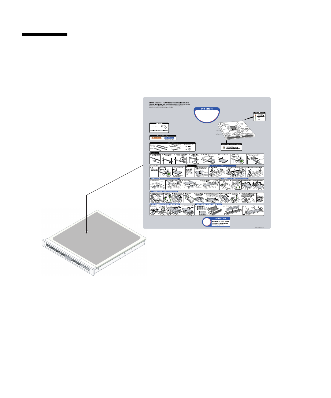
Alert Labels
The followings are labels attached to this product:
■ Never peel off the labels.
■ The following labels provide information to the users of this product.
Sample of SPARC Enterprise T1000
xxii SPARC Enterprise T1000 Server Installation Guide • April 2007
Page 25

Reader's Comment Form
Preface xxiii
Page 26
FOLD AND TAPE
NO POSTAGE
NECESSARY
IF MAILED
IN THE
UNITED STATES
BUSINESS REPLY MAIL
FIRST-CLASS MAIL PERMIT NO 741 SUNNYVALE CA
POSTAGE WILL BE PAID BY ADDRESSEE
FUJITSU COMPUTER SYSTEMS
AT T E NT I ON ENGINEERING OPS M/S 249
1250 EAST ARQUES AVENUE
P O BOX 3470
SUNNYVALE CA 94088-3470
FOLD AND TAPE
xxiv SPARC Enterprise T1000 Server Installation Guide • April 2007
Page 27

CHAPTER
1
Preparing for Installation
This chapter describes the server installation, and provides background information
about the installation procedures that begin in Chapter 2.
This chapter contains these topics:
■ “Tools Needed” on page 2
■ “Optional Components” on page 3
■ “Installation Overview” on page 3
■ “Slide Rail Assembly Notes” on page 5
■ “Cable Management Notes” on page 7
■ “Data Port and Cabling Notes” on page 8
■ “Safety Precautions” on page 9
1
Page 28

Server Overview
FIGURE 1-1 shows the server.
FIGURE 1-1 Server
Tools Needed
■ No. 2 Phillips screwdriver
■ ESD mat and grounding strap
2 SPARC Enterprise T1000 Server Installation Guide • April 2007
Page 29

Optional Components
The standard components of the server are installed at the factory. However, if you
ordered options such as additional memory or a PCI card, these may be shipped
separately. Install these components prior to installing the server in a rack.
If you ordered any other options that are not factory-installed, see the SPARC
Enterprise T1000 Server Service Manual for installation instructions.
Note – All internal components must be installed only by qualified service
technicians.
Caution – Electrostatic damage can permanently disable the system or require
repair by service technicians. Place components on an antistatic surface, such as an
antistatic discharge mat, an antistatic bag, or a disposable antistatic mat. Wear an
antistatic grounding strap connected to a metal surface on the chassis when you
work on system components.
Note – The list of optional components can be updated without notice.
Installation Overview
This installation guide provides procedures that must be performed in the following
order.
1. Verify that you have received all of the components that ship with your server.
2. Gather configuration information for your system. See your system administrator
for specific details, including these parameters:
■ Gateway IP address
■ IP address for the system controller
■ Netmask
3. Install any optional components shipped with your system. If you have
purchased other optional components such as additional memory, install them
prior to mounting the server in a rack. See “Optional Components” on page 3.
Chapter 1 Preparing for Installation 3
Page 30

4. Mount the server into a rack or equipment cabinet. See “To Install the Server in
the Rack” on page 19.
Note – In the rest of this document, the term rack means either an open rack or a
closed cabinet.
5. Connect the server to a serial terminal or a terminal emulator (PC or workstation)
to display system messages. See “Powering On the Server for the First Time” on
page 25.
Tip – The serial terminal or a terminal emulator should be connected before you
connect the power cables. As soon as AC power is connected to the system, the
system controller immediately powers on and runs diagnostics. Diagnostic test
failures will be printed on the serial terminal. For more information, refer to the
Advanced Lights Out Management (ALOM) CMT Guide.
6. Connect the data cables to the server, but do not connect the AC power cable yet.
See “Connecting the Server Cables” on page 21.
7. Connect the AC power cable to the server and examine the display for any error
messages. See “Powering On the Server for the First Time” on page 25.
Caution – There is a potential for electric shock if the server and related equipment
are not properly grounded.
Note – The system controller (SC) runs on the 3.3v standby voltage. As soon as AC
power is connected to the system, the system controller immediately powers on,
runs diagnostics, and initializes the ALOM CMT firmware.
8. After the system controller boots, access the ALOM CMT command-line interface
through the serial management port. See “To Log In To the System Controller
Using the Serial Management Port” on page 29.
9. Configure the SC network management port. See “To Configure the System
Controller Network Management Port” on page 31.
10. Enable the new configuration by resetting the system controller. See “To Reset
the System Controller” on page 34.
11. Power on the server using the ALOM CMT software. See “To Initiate the Power
On Sequence” on page 36.
12. Configure the Solaris OS. See “To Boot the Solaris Operating System” on page 39.
4 SPARC Enterprise T1000 Server Installation Guide • April 2007
Page 31

The Solaris OS is preinstalled on the server. When you power on, you are
automatically guided through the Solaris OS configuration procedure. See “To
Boot the Solaris Operating System” on page 39.
13. Install any required patch or patches to the server.
Refer to the product notes for a list of the required patches.
14. (Optional) Load additional software from the Solaris media kit.
The Solaris media kit (sold separately) includes several CDs containing software
to help you operate, configure, and administer your server. Refer to the
documentation provided with the media kit for a complete listing of included
software and detailed installation instructions.
Slide Rail Assembly Notes
The rackmount kit has two slide rail assemblies. Each slide rail assembly can be
installed on either the right or left side of the rack.
A slide rail assembly consists of three main sections, a front section, a sliding rear
section, and a removable mounting bracket (
includes two extension brackets.
FIGURE 1-2). The rackmount kit also
Mounting bracket
(shown removed)
Front section
FIGURE 1-2 Slide Rail Assembly
Extension bracket
Rear section
Chapter 1 Preparing for Installation 5
Page 32

The slide rail assembly has the following features:
■ The front and rear sections form the slide rail. The front and rear sections expand
to fit rack depths from 24 in. (610 mm) to 29.0 in. (740 mm).
■ Extension brackets are included in the mounting rail kit. The extension brackets
add 2.9 in. (73 mm) to the length of each slide rail.
■ The mounting bracket slides 13 in. (330 mm) out of the slide rail, then locks in
place. If you unlock the mounting bracket, it slides an additional 4 in. (100 mm)
before separating from the slide rail. The mounting brackets mount directly to the
sides of the server chassis.
■ There are two locks on each server mounting bracket (FIGURE 1-3). The lock
enables the mounting bracket to slide forward. The mounting bracket release
allows you to remove the mounting bracket from the slide rail. You also use the
release when pushing the mounting bracket into the slide rail.
FIGURE 1-3 Mounting Bracket Locks
6 SPARC Enterprise T1000 Server Installation Guide • April 2007
Mounting bracket release
Mounting bracket lock (2 buttons)
Page 33

Cable Management Notes
A cable management bracket (FIGURE 1-4) is included in the server slide rail kit. The
cable management bracket clips onto the slide rails. Use cable ties or cable straps to
attach cabling to the bracket.
FIGURE 1-4 Cable Management Bracket
Chapter 1 Preparing for Installation 7
Page 34

Data Port and Cabling Notes
Port Locations
FIGURE 1-5 shows the ports on the server.
AC in
FIGURE 1-5 Locations of Ports and Connectors on the Rear Panel
NET3
NET2
NET1
NET0
SC network management port
SC serial management port
Serial port
Cabling Notes
The following list describes the server’s cable connections and ports:
■ Minimum cable connections for the server:
■ At least one system on-board Ethernet network connection (NET port)
■ System controller serial management port (SERIAL MGT port)
■ System controller network management port (NET MGT port)
■ Power cable
■ System controller (SC) management ports. There are two SC management ports
for use with the ALOM CMT system controller.
■ The SC serial management port (labeled SERIAL MGT) uses an RJ-45 cable and
is always available. This is the default connection to the ALOM CMT system
controller.
■ The SC network management port (labeled NET MGT) is the optional
connection to the ALOM CMT system controller. See “To Configure the System
Controller Network Management Port” on page 31. The SC network
management port uses an RJ-45 cable for a 10/100BASE-T connection. This
port does not support connections to Gigabit networks.
See the SPARC Enterprise T1000 Server Overview for more information.
8 SPARC Enterprise T1000 Server Installation Guide • April 2007
Page 35

■ Ethernet ports. The server Ethernet interfaces operate at 10 Mbps, 100 Mbps, and
1000 Mbps. The transfer rates for the Ethernet ports are given in
TABLE 1-1 Ethernet Connection Transfer Rates
Connection Type IEEE Terminology Transfer Rate
Ethernet 10BASE-T 10 Mbit/sec
Fast Ethernet 100BASE-TX 100 Mbits/sec
Gigabit Ethernet 1000BASE-T 1000 Mbit/sec
■ TTYA serial port. Use the DB-9 connector with a null modem cable for serial
TABLE 1-1.
devices. This port appears as ttya in Solaris OS and OpenBoot PROM™
messages. This port is not connected to the SC serial management port.
■ AC power cables. As soon as the AC power cables are connected to the power
source, the server goes into standby mode and the ALOM CMT system controller
initializes.
Tip – The serial terminal or a terminal emulator should be connected before you
connect the power cables. As soon as AC power is connected to the system, the
system controller immediately powers on and runs diagnostics. Diagnostic test
failures will be printed on the serial terminal. For more information, refer to the
Advanced Lights out Management (ALOM) CMT v1.x Guide.
Safety Precautions
Caution – Deploy the antitilt feature for your equipment rack before beginning the
installation.
Chapter 1 Preparing for Installation 9
Page 36

10 SPARC Enterprise T1000 Server Installation Guide • April 2007
Page 37

CHAPTER
2
Installing the Server
This chapter provides instructions for installing the server in an equipment rack.
This chapter contains the following sections:
■ “Rackmount Kit” on page 11
■ “Installing the Server in a Rack” on page 12
■ “Removing the Server From the Rack for Service” on page 21
■ “Connecting the Server Cables” on page 21
Note – Ensure that you have all of the parts before you begin the installation of the
server.
Note – In this guide, references to left and right are from your viewpoint as you face
either the front or the rear of the system.
Rackmount Kit
The server rackmount kit includes two mounting slides, a slide spacing tool, and a
cable management bracket. The kit also includes two extension brackets for use with
racks up to 39.5 in. (1000 mm) in depth.
The mounting kit also includes an assortment of screws and nuts to fit various types
of racks. Extra screws and nuts are included.
11
Page 38

Installing the Server in a Rack
▼ To Install the Mounting Brackets
1. Pull both mounting brackets completely out of their respective slide rails.
a. Simultaneously press and hold the upper and lower lock buttons of the slide
rail lock (
FIGURE 2-1).
FIGURE 2-1 Unlocking the Slide Rail Assembly
b. Pull the mounting bracket out until it stops.
c. Slide the mounting bracket release button to the left (
mounting bracket completely out of the slide rail.
12 SPARC Enterprise T1000 Server Installation Guide • April 2007
FIGURE 2-2), then slide the
Page 39

FIGURE 2-2 Mounting Bracket Release Button
2. Attach a mounting bracket to the right side of the server chassis.
a. Position the mounting bracket against the server chassis (
FIGURE 2-3) so that the
slide rail lock is at the front and the two keyed openings on the mounting
bracket are aligned with the two locating pins on the side of the chassis.
Chapter 2 Installing the Server 13
Page 40
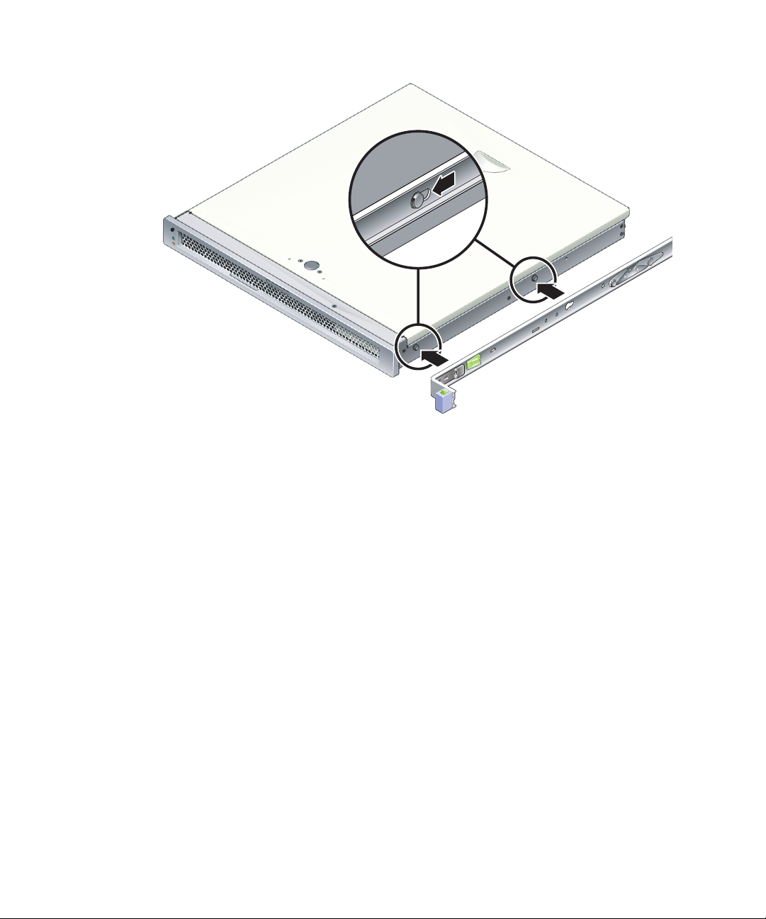
FIGURE 2-3 Attaching a Mounting Bracket to the Chassis
b. With the heads of the two locating pins protruding though the two keyed
openings in the mounting bracket, slide the mounting bracket toward the front
of the chassis until the bracket locks into place with an audible click.
c. Verify that both locating pins are trapped in the keyed openings and that the
front locating pin has engaged the mounting bracket lock (
FIGURE 2-3).
3. Attach the second mounting bracket to the left side of the server chassis.
14 SPARC Enterprise T1000 Server Installation Guide • April 2007
Page 41

▼ To Install the Slide Rails
1. Determine which rack hole numbers you will use when attaching the slide rails to
the rack posts.
Most racks have posts that are marked off by rack units (1.75 in. or 45 mm). The
server occupies one rack unit.
2. Determine which screws you will use to mount the slide rails.
■ If your rack has threaded mounting holes in the rack posts, determine whether
the threads are metric or standard. Select the appropriate screws from the package
included in the mounting kit.
■ If your rack does not have threaded mounting holes, the mounting screws go
through bracket and rack post, and are secured with a caged nut. Select the
appropriate screws and nuts from the package included in the mounting kit.
3. Loosen the two captive screws (
FIGURE 2-4) approximately a quarter-turn on each
slide rail.
This action allows movement of the rear section so that you can adjust the length of
each slide rail.
Front
FIGURE 2-4 Captive Screws on the Slide Rail
Chapter 2 Installing the Server 15
Page 42

4. Determine if the slide rails require an extension bracket.
Most rack installations do not require slide rail extension brackets. However, you
may need to install the extension brackets under the following conditions:
■ If your rack is deeper than 29.0 in (740mm).
■ If your rack requires the ends of the slide rails to be side mounted.
If required, use M6 screws to attach an extension bracket to the rear of each slide
rail, as shown in
FIGURE 2-5.
Rear
FIGURE 2-5 Using the Extension Bracket
Note – In some very rare cases, it may be necessary to mount the extension bracket
with its side flange facing forward.
16 SPARC Enterprise T1000 Server Installation Guide • April 2007
Page 43

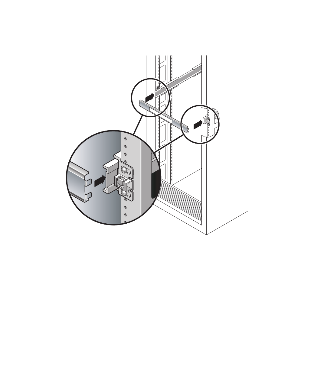
5. Attach a slide rail to the right front rack post (FIGURE 2-6).
a. Loosely attach the front of a slide rail to the right front rack post using two
screws (M5 or M6, as appropriate to the size of the screw holes on the rack
post).
Do not tighten the screws yet.
Front
FIGURE 2-6 Mounting the Slide Rail
b. Adjust the length of the slide rail by sliding the rear section to reach the
outside edge of the rear rack post, then tighten the captive screws (
FIGURE 2-4)to
freeze the length of the slide rail.
c. Loosely attach the rear of the slide rail to the rear rack post with screws.
6. Attach the second slide rail to the left rack posts in a similar manner.
Do not tighten the attachment screws at the front or rear of the slide rail.
7. Use the slide rail spacing tool to adjust the distance between the slide rails.
Chapter 2 Installing the Server 17
Page 44
a. At the rear of the rack, insert the left side of the tool into slots at the end of the
middle section on the left slide rail (
FIGURE 2-7).
FIGURE 2-7 Using the Slide Rail Spacing Tool to Adjust the Distance Between the Slide
Rails
b. Insert the right side of the tool into slots at the end of the right rail, while
simultaneously sliding the end of the rail to the right or left as needed to allow
the ends of the tool to enter both middle sections.
When the tool is properly inserted, the distance between the rails is 17.4 in. (442
mm).
c. Tighten the screws to lock the ends of the slide rails in place.
d. Remove the slide rail spacing tool.
18 SPARC Enterprise T1000 Server Installation Guide • April 2007
Front
Page 45

e. At the front of the rack, use the spacing tool to adjust the distance between the
front ends of the rails.
The front ends of the rails do not have slots for the spacing tool. Slide the rails
sideways as needed until the sides of the spacing tool touch both rails. At this
point, the distance between the ends of the rails is 17.4 in. (442 mm).
f. Tighten the two screws to lock the rails in place.
▼ To Install the Server in the Rack
1. Deploy the antitilt feature, if the rack is so equipped.
Caution – Deploy the antitilt feature on the rack before beginning an installation.
Chapter 2 Installing the Server 19
Page 46

2. Raise the server and insert the ends of the mounting brackets into the left and
right slide rails (
FIGURE 2-8).
Front
FIGURE 2-8 Mounting the Chassis on the Slide Rails
3. Slide the chassis into the rack.
Caution – Before continuing, verify that the server is securely mounted in the rack,
and that the slide rails are locked in the mounting brackets.
▼ To Install the Cable Management Bracket
1. Place the cable management bracket across the slide rail assemblies behind the
system chassis.
2. Press down on each end of the cable management bracket until the ends click into
place on the mounting brackets.
20 SPARC Enterprise T1000 Server Installation Guide • April 2007
Page 47

Note – When you attach cables to the server, as in the following procedures, lay the
cables over the cable management bracket, then use cable ties to hold each cable in
place.
Removing the Server From the Rack for Service
To install or replace internal parts in the server, you must first remove the server
from the rack.
For the removal procedure, refer to the SPARC Enterprise T1000 Server Service
Manual.
Connecting the Server Cables
To boot the server, you must connect and configure the network and serial ports. The
procedures are given in the following sections.
■ “To Connect the SC Serial Management Port” on page 22
■ “To Connect the SC Network Management Port” on page 22
■ “To Connect the Ethernet Network Cables” on page 23
■ “To Connect the AC Power Cable to the Server” on page 23
FIGURE 2-9 shows the connectors on the rear panel of the server.
AC in
FIGURE 2-9 Rear Panel Connectors
NET3
NET2
NET1
NET0
TTYA serial port
Chapter 2 Installing the Server 21
SC network management port
SC serial management port
Page 48

▼ To Connect the SC Serial Management Port
The system controller serial management port is marked SER MGT (FIGURE 2-10).
SER MGT NET MGT
FIGURE 2-10 System Controller Serial and Network Ports, Rear of Chassis
Note – Use the SC serial management port only for server management. It is the
default connection between the system controller and a terminal or a computer.
Caution – Do not attach a modem to this port.
● Connect a Category 5 cable from the SER MGT serial management port to the
terminal device.
When connecting either a DB-9 or a DB-25 cable, use an adapter to perform the
crossovers given for each connector.
▼ To Connect the SC Network Management Port
The system controller network management port is marked NET MGT (FIGURE 2-10).
Note – The SC network management port is configured by default to retrieve
network settings via Dynamic Host Configuration Protocol (DHCP) and allow
connections using Solaris Secure Shell (SSH
settings for your network. Instructions are given in Chapter 3.
● Connect a Category 5 cable from the NET MGT network management port to your
network switch or hub.
22 SPARC Enterprise T1000 Server Installation Guide • April 2007
®
). You might need to modify these
Page 49

▼ To Connect the Ethernet Network Cables
The server has four network connectors, marked NET0, NET1, NET2, and NET3
(
FIGURE 2-9). These connectors are RJ-45 Gigabit Ethernet.
1. Connect a Category 5 cable from your network switch or hub to Ethernet Port 0
(NET0) on the rear of the chassis.
NET0 is the farthest left port in the 4-port network cluster in
2. Connect Category 5 cables from your network switch or hub to the remaining
Ethernet ports (NET1, NET2, NET3), as needed.
FIGURE 2-9.
TTYA Serial Port
The TTYA serial port has a DB-9 connector. A DB-9 to RJ-45 adapter cable is
included in the shipping kit.
Note – This serial port is not the same as the SC serial management port. Use the
serial port only for general-purpose serial data transfers.
15
69
FIGURE 2-11 Serial Port (TTYA)
▼ To Connect the AC Power Cable to the Server
Powering on the system for the first time requires special preparation and
procedures. For example, if you have not prepared a display before connecting the
AC power cable, system messages might be lost.
1. Finish the hardware procedures in this chapter, but do not attach the AC power
cable yet.
Powering on the system for the first time requires special preparation and
procedures. For example, if you have not prepared a display before connecting the
AC power cable, system messages may be lost. You will be instructed to connect the
server to AC power in “Powering On the Server for the First Time” on page 25.
Chapter 2 Installing the Server 23
Page 50

Caution – The server goes into Standby mode and the system controller initializes
as soon as the AC power cable is connected to the power source.
2. Go to “Powering On the Server for the First Time” on page 25.
24 SPARC Enterprise T1000 Server Installation Guide • April 2007
Page 51

CHAPTER
3
Powering On the System
This chapter includes instructions for booting the server and for enabling the system
controller network management port.
The following topics are discussed:
■ “Powering On the Server for the First Time” on page 25
■ “Logging In To the ALOM CMT System Controller” on page 29
■ “Using the ALOM CMT System Controller for Common Operations” on page 35
■ “Booting the Solaris Operating System” on page 39
Powering On the Server for the First Time
Power On Overview
System Console
When you power on the system, the boot process begins under the control of the
system console. The system console displays status and error messages generated by
firmware-based tests during system startup.
25
Page 52

Note – To see these status and error messages, connect a terminal or terminal
emulator to the serial management port (SERIAL MGT). For a basic procedure to
connect a terminal or terminal emulator, see “To Power On the System for the First
Time” on page 27.
For a more detailed discussion on configuring the system console and connecting
terminals, refer to the SPARC Enterprise T1000 Server Administration Guide.
ALOM CMT System Controller
After the system console finishes its low-level system diagnostics, the ALOM CMT
system controller initializes and runs a higher level of diagnostics. When you access
the ALOM CMT system controller using a device connected to the serial
management port, you see the output of the ALOM CMT diagnostics.
By default, the network management port is configured to automatically retrieve
network configuration using Dynamic Host Configuration Protocol (DHCP) and to
allow connections using Secure Shell (SSH).
Note – If you are unable to use DHCP and SSH on your network, you must connect
to the ALOM CMT system controller using the serial management port to
reconfigure the network management port. See “To Configure the System Controller
Network Management Port” on page 31.
Once the network management port (NET MGT) has been assigned an IP address,
you can connect to the ALOM CMT system controller using Telnet or SSH.
Passwords
There is no default password when connecting to the ALOM CMT system controller
for the first time using the serial management port. To set the admin password, see
“To Log In To the System Controller Using the Serial Management Port” on page 29.
When connecting to the ALOM CMT system controller using the network
management port for the first time, the default password is the last eight digits of
the chassis serial number. The serial number is located on the rear of the server. It is
also printed on the system information sheet that shipped with the server.
26 SPARC Enterprise T1000 Server Installation Guide • April 2007
Page 53

▼ To Power On the System for the First Time
Tip – The serial terminal or a terminal emulator should be connected before you
connect the power cable, or you will not see the system messages. The server goes
into standby mode and the ALOM CMT system controller initializes as soon as the
AC power cable is connected to the power source.
Note – If you are not logged in, ALOM CMT times out after 60 seconds and reverts
to the system console. For more information, refer to the Advanced Lights Out
Management (ALOM) CMT Guide.
The system controller runs on the 3.3v standby voltage. As soon as AC power is
connected to the system, the system controller powers on, runs diagnostics, and
initializes the ALOM CMT firmware.
1. Connect a terminal or a terminal emulator (PC or workstation) to the SC serial
management port.
Configure the terminal or terminal emulator with these settings:
■ 9600 baud
■ 8 bits
■ No parity
■ 1 Stop bit
■ No handshaking
2. Turn on the terminal or terminal emulator.
3. Connect the AC power cable to the server and watch the terminal for system
messages.
AC in
FIGURE 3-1 AC Connector
Chapter 3 Powering On the System 27
Page 54

After the system controller boots, the system controller login prompt is displayed on
the serial console. The following example shows a partial output from the system
controller boot sequence leading to the login prompt.
CODE EXAMPLE 3-1 Boot Sequence Example
ALOM BOOTMON v1.x
ALOM Build Release: 000
Reset register: f0000000 EHRS ESRS LLRS SWRS
ALOM POST 1.x
Dual Port Memory Test, PASSED.
TTY External - Internal Loopback Test
TTY External - Internal Loopback Test, PASSED.
TTYC - Internal Loopback Test
TTYC - Internal Loopback Test, PASSED.
....................
ETHERNET CPU LOOPBACK TEST, PASSED
Full VxDiag Tests - PASSED
Status summary - Status = 7FFF
VxDiag - - PASSED
POST - - PASSED
LOOPBACK - - PASSED
I2C - - PASSED
EPROM - - PASSED
FRU PROM - - PASSED
ETHERNET - - PASSED
MAIN CRC - - PASSED
BOOT CRC - - PASSED
TTYD - - PASSED
TTYC - - PASSED
MEMORY - - PASSED
28 SPARC Enterprise T1000 Server Installation Guide • April 2007
Page 55

CODE EXAMPLE 3-1 Boot Sequence Example (Continued)
MPC885 - - PASSED
sc>
Note – If it receives no user input within 60 seconds, the ALOM CMT system
controller console automatically connects to the system console.
Logging In To the ALOM CMT System Controller
You can log in to the system controller through either the serial management port or
the network management port.
▼ To Log In To the System Controller Using the
Serial Management Port
After the system controller boots, you can access the ALOM CMT command-line
interface to configure and manage the system.
The sc prompt is displayed the first time the system controller is booted. The default
configuration provides an ALOM CMT user account called admin. There is no
default password, so you must create a password using the system controller
password command.
Chapter 3 Powering On the System 29
Page 56

1. If this is the first time the system has been powered on, use the password
command to set the admin password.
.........................
TTYD - - PASSED
TTYC - - PASSED
MEMORY - - PASSED
MPC885 - - PASSED
sc> password
password: Changing password for admin
Setting password for admin.
New password: new-password
Re-enter new password: new-password
sc>
After the admin password has been set, on subsequent reboots, the sc login prompt
is displayed.
2. Enter admin for the login name followed by your password.
TTYD - - PASSED
TTYC - - PASSED
MEMORY - - PASSED
MPC885 - - PASSED
Please login: admin
Please Enter password: password
(Press Return twice)
sc>
▼ To Log In To the System Controller Using the
Network Management Port
The SC network management port is configured by default to retrieve network
settings through DHCP and allow connections using SSH.
After the network management port (NET MGT) has been assigned an IP address by
a DHCP server, you can connect to the ALOM CMT system controller using SSH.
30 SPARC Enterprise T1000 Server Installation Guide • April 2007
Page 57

Note – If you are unable to use DHCP and SSH on your network, you must connect
to the ALOM CMT system controller using the serial management port to
reconfigure the network management port. See “To Configure the System Controller
Network Management Port” on page 31.
1. Open a Telnet or SSH session and connect to the system controller by specifying
its network address.
The following example shows a Telnet session.
% telnet xxx.xxx.xx.xx
Trying xxx.xxx.xx.xx...
Connected to xxx.xxx.xx.xx.
Escape character is '^]'.
Advanced Lights Out Manager 1.x
Please login:
2. Login as admin using the password you previously set.
Please login: admin
Please Enter password: password
sc>
▼ To Configure the System Controller Network
Management Port
Note – If your network allows the use of DHCP and SSH, this configuration is
performed automatically at the first time you boot the system.
Use this procedure only if:
■ If you are unable to use DHCP and SSH on your network.
■ If you need to modify the SC network management port settings.
In this procedure you connect to the ALOM CMT system controller using the serial
management port to manually reconfigure the network management port.
Note – For more information on configuring ALOM CMT, refer to the Advanced
Lights Out Management (ALOM) CMT Guide.
Chapter 3 Powering On the System 31
Page 58

You set these network parameters according to the specific details of your network
configuration:
■ if_network – Specifies whether the SC is on the network or not
■ netsc_ipaddr – IP address of the system controller
■ netsc_ipgateway – IP address of the gateway for the subnet
■ netsc_ipnetmask – Netmask for the system controller subnet
To configure these parameters, use the setsc command. The usage is:
sc> setsc parameter
1. Set the if_network parameter to true.
sc> setsc if_network true
2. Set the if_connection parameter to the connection type, either telnet or ssh.
sc> setsc if_connection value
where the value can be one of the following:
■ none
■ telnet
■ ssh
■ netsc_dhcp (The system controller obtains its network interface configuration
through a DHCP server.)
See the Advanced Lights Out Management (ALOM) CMT Guide for more information
about SSH support in ALOM CMT.
3. Choose one of these methods to configure the system controller using information
from your network administrator:
■ Use DHCP to retrieve the network settings. Go to Step 4.
■ Configure a static IP configuration. Go to Step 5.
4. If you choose to use DHCP, set netsc_dhcp to true.
sc> setsc netsc_dhcp true
Go to Step 6.
5. If you choose to use a static IP configuration, set the parameters netsc_ipaddr,
netsc_ipgateway, and netsc_ipnetmask, as follows.
32 SPARC Enterprise T1000 Server Installation Guide • April 2007
Page 59

a. Set the IP address for the system controller.
sc> setsc netsc_ipaddr service-processor-IPaddr
b. Set the IP address for the system controller gateway.
sc> setsc netsc_ipgateway gateway-IPaddr
c. Set the netmask for the system controller.
sc> setsc netsc_ipnetmask 255.255.255.0
This example uses 255.255.255.0 to set the netmask. Your network environment
subnet might require a different netmask. Use a netmask number most appropriate
to your environment.
6. Use the showsc command to verify that the parameters were set correctly.
sc> showsc
Advanced Lights Out Manager CMT v1.x
parameter value
--------- -----
if_network true
if_connection ssh
if_emailalerts false
netsc_dhcp true
netsc_ipaddr xxx.xxx.xxx.xxx
netsc_ipnetmask 255.255.255.0
netsc_ipgateway 0.0.0.0
mgt_mailhost
mgt_mailalert
sc_customerinfo
sc_escapechars #.
sc_powerondelay false
sc_powerstatememory false
sc_clipasswdecho true
sc_cliprompt sc
sc_clitimeout 0
sc_clieventlevel 2
sc_backupuserdata true
diag_trigger power-on-reset error-reset
Chapter 3 Powering On the System 33
Page 60

diag_verbosity normal
diag_level max
diag_mode normal
sys_autorunonerror false
ser_baudrate 9600
ser_parity none
ser_stopbits 1
ser_data 8
netsc_enetaddr xx:xx:xx:xx:xx:xx
sys_enetaddr yy:yy:yy:yy:yy:yy
Note – After setting the configuration parameters, you must reset the system
controller for the new values to take affect. See “To Reset the System Controller” on
page 34.
▼ To Reset the System Controller
● Issue the resetsc command.
You are prompted to confirm that you want to reset the system controller. Type y
when prompted.
sc> resetsc
Are you sure you want to reset the SC [y/n]? y
User Requested SC Shutdown
Note – To bypass the confirmation message, specify the –y flag to the resetsc
command.
The system controller resets, runs diagnostics, and returns to the login prompt.
ALOM POST 1.x
Dual Port Memory Test, PASSED.
TTY External - Internal Loopback Test
TTY External - Internal Loopback Test, PASSED.
TTYC - Internal Loopback Test
34 SPARC Enterprise T1000 Server Installation Guide • April 2007
Page 61

TTYC - Internal Loopback Test, PASSED.
TTYD - Internal Loopback Test
TTYD - Internal Loopback Test, PASSED.
....................
Full VxDiag Tests - PASSED
Status summary - Status = 7FFF
VxDiag - - PASSED
POST - - PASSED
LOOPBACK - - PASSED
I2C - - PASSED
EPROM - - PASSED
FRU PROM - - PASSED
ETHERNET - - PASSED
MAIN CRC - - PASSED
BOOT CRC - - PASSED
TTYD - - PASSED
TTYC - - PASSED
MEMORY - - PASSED
MPC885 - - PASSED
Please login:
Using the ALOM CMT System Controller for Common Operations
Note – For more information on using ALOM CMT, refer to the Advanced Lights Out
Management (ALOM) CMT Guide.
Chapter 3 Powering On the System 35
Page 62

▼ To Initiate the Power On Sequence
Powering on the system requires you to use the poweron command at the SC
console.
● To initiate the power-on sequence, issue the poweron command.
You see an sc> alert message on the system console. This indicates that the system
has reset.
sc> poweron
SC Alert: Host System has Reset
sc>
▼ To Connect to the System Console
Output from POST, OpenBoot, and the Solaris OS is displayed in the system console
using the console command on the system controller.
● Execute the console command, and use the –f option to force the console to be
attached to your session.
Multiple users can be connected to the console, but only one can be attached.
sc> console –f
#. (Enter #. to return to ALOM)
36 SPARC Enterprise T1000 Server Installation Guide • April 2007
Page 63

▼ To Perform a Normal System Initialization
After you issue the poweron command, the CPU and memory controllers initialize
and eventually OpenBoot initializes. After a number of system messages, the ok
prompt appears.
The example output below is a small section of the complete output.
CODE EXAMPLE 3-2 Example of Normal System Initialization Output
sc> poweron -c
Enter #. to return to ALOM
SC Alert: Host System has Reset
0:0>
0:0>@(#) SPARC Enterprise T1000 Integrated POST 4.x.0 2005/06/14
12:19
0:0>VBSC selecting POST MAX Testing.
0:0>VBSC enabling L2 Cache.
0:0>VBSC enabling Full Memory Scrub.
....................
Find dropin, Copying Done, Size 0000.0000.0000.1110
Find dropin, (copied), Decompressing Done, Size
0000.0000.0006.06e0 ^Qcpu cpu cpu cpu cpu cpu cpu cpu cpu cpu cpu
cpu cpu cpu cpu cpu cpu cpu cpu cpu cpu cpu cpu cpu cpu cpu cpu
cpu vpci mem32base, mem64base, cfgbase: e800000000 e000000000
e900000000
pci /pci@780: Device 0 pci pci
/pci@780/pci@0: Device 0 Nothing there
/pci@780/pci@0: Device 1 pci pci
....................
/pci@7c0/pci@0: Device a Nothing there
/pci@7c0/pci@0: Device b Nothing there
/pci@7c0/pci@0: Device c Nothing there
/pci@7c0/pci@0: Device d Nothing there
/pci@7c0/pci@0: Device e Nothing there
/pci@7c0/pci@0: Device f Nothing there
Probing I/O buses
SPARC Enterprise T1000, No Keyboard
OpenBoot FW build_11***PROTOTYPE_BUILD***, 16376 MB memory
installed, Serial #51454515.
Chapter 3 Powering On the System 37
Page 64

CODE EXAMPLE 3-2 Example of Normal System Initialization Output (Continued)
[firmware obp4.x #0]
Ethernet address xx:xx:xx:xx:xx:xx, Host ID: xxxxx.
{0} ok
For additional tests and to verify system functionality, see the SPARC Enterprise
T1000 Server Administration Guide and the OpenBoot firmware documentation.
To understand the various devices and their path names as represented in the
OpenBoot device tree, refer to
TABLE 3-1. The table identifies each of the devices, their
full path name, and their location or NAC name used to identify their physical
location.
TABLE 3-1 Server Device List
Identifier Device Device Path (Location)
MB/CMP0/Pn cpun /cpu@n, where n = {0..31}
MB/CMP0/CH0/R0/D0 dimm0 (CH0/R0/D0/J0501)
MB/CMP0/CH0/R0/D1 dimm1 (CH0/R0/D1/J0601)
MB/CMP0/CH0/R1/D0 dimm2 (CH0/R1/D0/J0701)
MB/CMP0/CH0/R1/D1 dimm3 (CH0/R1/D1/J0801)
MB/CMP0/CH3/R0/D0 dimm4 (CH1/R0/D0/J1001)
MB/CMP0/CH3/R0/D1 dimm5 (CH1/R0/D1/J1101)
MB/CMP0/CH3/R1/D0 dimm6 (CH1/R1/D0/J1201)
MB/CMP0/CH3/R1/D1 dimm7 (CH1/R1/D1/J1301)
MB/PCIEa pci0 /pci@780
MB/PCIEb pci1 /pci@7c0
PCIE0 slot0 /pci@780/pci@0
MB/GBE0 net0
net1
MB/GBE1 net2
net3
MB/HBA SCSI /pci@7c0/pci@0/pci@8/scsi@2
/pci@7c0/pci@0/network@4
/pci@7c0/pci@0/network@4,1
/pci@7c0/pci@0/pci@8/network@1
/pci@7c0/pci@0/pci@8/network@1,1
38 SPARC Enterprise T1000 Server Installation Guide • April 2007
Page 65

Booting the Solaris Operating System
The Solaris OS is preinstalled on the disk drive (for server configurations that
include a hard drive). The Solaris OS is not configured. If you boot the server from
this drive, you will be prompted to configure the Solaris OS for your environment.
▼ To Boot the Solaris Operating System
● Type the boot command at the ok prompt.
You must append a target to the disk path. For example, the target can be disk0 or a
device or network path.
In the following example, the server is booted from disk 0 (zero).
CODE EXAMPLE 3-3 Example of Server Boot from Disk 0
ok boot disk0
Boot device: /pci@7c0/pci@0/pci@8/scsi@2/disk@0,0
File and args:
Notice: Unimplemented procedure 'encode-unit' in
/pci@7c0/pci@0/pci@2/pci@0/LSILogic,sas@4
Loading ufs-file-system package 1.4 04 Aug 1995 13:02:54.
FCode UFS Reader 1.12 00/07/17 15:48:16.
Loading: /platform/SUNW,T1000/ufsboot
Loading: /platform/sun4v/ufsboot
....................
Hostname: wgs94-181
The system is coming up. Please wait.
NIS domain name is x.x.x.x
starting rpc services: rpcbind keyserv ypbind done.
Setting netmask of lo0 to 255.0.0.0
Setting netmask of bge0 to 255.255.255.0
Setting default IPv4 interface for multicast: add net 224.0/4:
gateway xxxx
syslog service starting.
volume management starting.
Creating new rsa public/private host key pair
Creating new dsa public/private host key pair
The system is ready.
wgs94-181 console login:
Chapter 3 Powering On the System 39
Page 66

▼ (Optional) To Reset the System
● If it is necessary to reset the system, use the init 6 command.
# init 6
Note – Do not power the system off and on.
▼ To Power Cycle the System
If a simple reset does not clear a system problem, you can power the system off and
on with this procedure.
1. Halt the Solaris OS.
At the Solaris OS prompt, issue the init 0 command to halt the Solaris OS and to
return to the ok prompt.
# init 0
WARNING: proc_exit: init exited
syncing file systems... done
Program terminated
ok
2. Switch from the system console prompt to the SC console prompt by typing the
#. escape sequence.
ok #.
sc>
3. Using the SC console, type the poweroff command.
sc> poweroff -fy
SC Alert: SC Request to Power Off Host Immediately.
40 SPARC Enterprise T1000 Server Installation Guide • April 2007
Page 67

4. Type the poweron command.
sc> poweron
sc> SC Alert: Host System has Reset
5. Reconnect to the system console using the console command.
sc> console -f
Enter #. to return to ALOM.
The systems displays various messages, followed by the ok prompt.
Chapter 3 Powering On the System 41
Page 68

42 SPARC Enterprise T1000 Server Installation Guide • April 2007
Page 69

APPENDIX
A
Updating the Server Firmware
This appendix describes how to update the server firmware.
This appendix includes the following topics:
■ Flash Image Overview
■ Updating the Firmware
Flash Image Overview
The flash image consists of the following components:
■ System controller firmware
■ OpenBoot
■ POST
■ Reset/Comfit
■ Sequencer
■ Partition description
Updating the Firmware
The flashupdate command updates both the ALOM CMT system controller
firmware and the host firmware.
To use the features and fixes in subsequent firmware releases, perform this
procedure.
43
Page 70

▼ To Update the Firmware
1. Ensure that the ALOM CMT system controller network management port is
configured.
This is required to access the new flash image over the network. See “To
Configure the System Controller Network Management Port” on page 31.
2. Open a Telnet or SSH session and connect to the system controller.
The following example is for Telnet.
% telnet xxx.xxx.xx.xx
Trying xxx.xxx.xx.xx...
Connected to xxx.xxx.xx.xx.
Escape character is’^]’.
Please login:
3. Login as admin, using the password you defined during the configuration of
the system controller.
Please login: admin
Please Enter password: password
sc>
4. Execute the flashupdate command.
The flashupdate SC command updates the system controller flash image and the
host firmware. The flashupdate command requires the following information:
■ IP address of an FTP server on the network that can access the flash image.
■ Full path name to the flash image that the IP address can access.
■ Username and password of an account registered on the system that is specified by the IP
address.
The command usage is as follows:
flashupdate [-s IPaddr -f pathname] [-v]
where:
■ -s IPaddr is the IP address of any FTP server on the network that can access the
flash image
■ -f pathname is the full path name to the flash image
44 SPARC Enterprise T1000 Server Installation Guide • April 2007
Page 71

■ -v is the flag to turn on verbose message output
sc> flashupdate -s xxx.xxx.xx.xx -f pathname
Username: username
Password: password
............................................................... .
Update complete. Reset device to use new image.
sc>
5. Reset the system controller.
After the flash has been updated, you must reset the system controller for the new
image to take affect. To reset the system controller, issue the resetsc command, as
shown below.
Note – To bypass the confirmation prompt, you can use the -y flag with the
resetsc command. If resetsc is issued from a Telnet or SSH session, upon reset
the Telnet or SSH session will be terminated. The output from the reset will be
displayed on the serial console on the system controller.
sc> resetsc
Are you sure you want to reset the SC [y/n]? y
User Requested SC Shutdown
The system controller resets, runs diagnostics, and returns to the login prompt (on
the serial console), similar to
CODE EXAMPLE A-1 Typical Boot Sequence Following Firmware Update
CODE EXAMPLE A-1.
ALOM BOOTMON v1.2.0
ALOM Build Release: 000
Reset register: f0000000 EHRS ESRS LLRS SWRS
ALOM POST 1.0
Dual Port Memory Test, PASSED.
TTY External - Internal Loopback Test
TTY External - Internal Loopback Test, PASSED.
TTYC - Internal Loopback Test
TTYC - Internal Loopback Test, PASSED.
Appendix A Updating the Server Firmware 45
Page 72

CODE EXAMPLE A-1 Typical Boot Sequence Following Firmware Update
...
ETHERNET CPU LOOPBACK TEST, PASSED
Full VxDiag Tests - PASSED
Status summary - Status = 7FFF
VxDiag - - PASSED
POST - - PASSED
LOOPBACK - - PASSED
I2C - - PASSED
EPROM - - PASSED
FRU PROM - - PASSED
ETHERNET - - PASSED
MAIN CRC - - PASSED
BOOT CRC - - PASSED
TTYD - - PASSED
TTYC - - PASSED
MEMORY - - PASSED
MPC885 - - PASSED
sc>
46 SPARC Enterprise T1000 Server Installation Guide • April 2007
Page 73

APPENDIX
B
Selecting a Boot Device
The boot device is specified by the setting of an OpenBoot configuration variable
called boot-device. The default setting of this variable is disk net. Because of
this setting, the firmware first attempts to boot from the system hard drive, and if
that fails, from the on-board NET0 Gigabit Ethernet interface.
This appendix includes the following topic:
■ Connecting the Network Interface to the Network
Connecting the Network Interface to the Network
To boot from a network, you must connect the network interface to the network.
This procedure assumes that you are familiar with the OpenBoot firmware and that
you know how to enter the OpenBoot environment. For more information, see the
SPARC Enterprise T1000 Server Administration Guide.
▼ To Connect the Network Interface to the
Network
● At the ok prompt, type:
ok setenv boot-device device-specifier
where the device-specifier is one of the following:
47
Page 74

■ disk – Specifies the system boot disk (internal disk 0 by default)
■ disk0 – Specifies internal drive 0
■ net, net0, net1– Specifies the network interfaces
■ full path name – Specifies the device or network interface by its full path name.
Note – The Solaris OS modifies the boot-device variable to its full path name, not
the alias name. If you choose a nondefault boot-device variable, the Solaris OS
specifies the full device path of the boot device.
Note – You can specify the name of the program to be booted as well as the way the
boot program operates. For more information, refer to the OpenBoot 4.x Command
Reference Manual for your specific Solaris OS release.
If you want to specify a network interface other than an on-board Ethernet interface
as the default boot device, you can determine the full path name of each interface by
typing:
ok show-devs
The show-devs command lists the system devices and displays the full path name
of each PCI device.
48 SPARC Enterprise T1000 Server Installation Guide • April 2007
Page 75

APPENDIX
C
Configuring the Network Management Port
If your server uses system firmware 6.2 or subsequent compatible versions, do not
perform the following configuration. Your ALOM CMT system controller network
management port is preconfigured at the factory.
If your server uses an earlier version of firmware than system firmware 6.2, you
must configure the network management port before you can use it.
This appendix includes the following topic:
■ Configuring the System Controller Network Manager Port
Configuring the System Controller Network Manager Port
▼ To Configure the System Controller Network
Management Port
To access the system controller using the network for the first time, you must first
configure the SC network management port through the SC serial management port.
You set these network parameters according to the specific details of your network
configuration:
■ if_network – Specified whether the SC is on the network or not
■ netsc_ipaddr – IP address of the system controller
■ netsc_ipgateway – IP address of the gateway for the subnet
49
Page 76

■ netsc_ipnetmask – Netmask for the system controller subnet
Note – For more information on configuring ALOM CMT, refer to the Advanced
Lights Out Management (ALOM) CMT Guide.
To configure these parameters you must use the setsc command. The usage is:
sc> setsc parameter
1. Set the netmask for the system controller.
sc> setsc netsc_ipnetmask 255.255.255.0
This example uses 255.255.255.0 to set the netmask. Your network environment
subnet might require a different netmask. Use a netmask number most appropriate
to your environment.
2. Set the IP address for the system controller.
sc> setsc netsc_ipaddr service-processor-IPaddr
3. Set the IP address for the system controller gateway.
sc> setsc netsc_ipgateway gateway-IPaddr
4. Set the if_network parameter to true.
sc> setsc if_network true
5. Use the showsc command to verify that the parameters were set correctly.
The showsc command displays all the configuration parameters and their values, as
shown in the example below.
50 SPARC Enterprise T1000 Server Installation Guide • April 2007
Page 77

Note – The network addresses and parameters shown in the examples are for
illustration purposes only. The four parameters marked with asterisks must be set
according to the specific details of your network configuration for the network
management port to function properly.
sc> showsc
Advanced Lights Out Manager CMT v1.x
parameter value
--------- -----
if_network* true
if_connection ssh
if_emailalerts false
netsc_dhcp true
netsc_ipaddr* xxx.xxx.xxx.xxx
netsc_ipnetmask* 255.255.255.0
netsc_ipgateway*
mgt_mailhost
mgt_mailalert
sc_customerinfo
sc_escapechars #.
sc_powerondelay false
sc_powerstatememory false
sc_clipasswdecho true
sc_cliprompt sc
sc_clitimeout 0
sc_clieventlevel 2
sc_backupuserdata true
diag_trigger power-on-reset error-reset
diag_verbosity normal
diag_level max
diag_mode normal
sys_autorunonerror false
ser_baudrate 9600
ser_parity none
ser_stopbits 1
ser_data 8
netsc_enetaddr xx:xx:xx:xx:xx:xx
sys_enetaddr yy:yy:yy:yy:yy:yy
xxx.xxx.xxx.xx
Appendix C Configuring the Network Management Port 51
Page 78

52 SPARC Enterprise T1000 Server Installation Guide • April 2007
Page 79

Index
Symbols
#., system console escape sequence, 40
A
AC power cable, 9
AC power, system controller, 4
adapters for serial cables, 22
adjusting length of slide rails, 15
admin command for firmware update, 44
admin password, setting, 30
admin user account, 29
ALOM CMT
60 second timeout if not logged in, 27
log in procedures, 29
passwords, 26
serial and network management ports, 8
alternate command for Telnet session, 44
B
baud rate for terminal, 27
bit setting for terminal, 27
boot command, 39
boot device setting, 47
boot order, 47
booting the Solaris OS, 39
brackets, cable management, 20
cables
adapters for serial data cables, 22
cable management bracket, 20
connections list, 8
component, internal, installation by qualified service
technician, 3
configuration information, software setup, 3
connecting to system console, 36
console command, 36, 41
D
default boot device, 47
deinstallation of server, 21
diagnostics, when run, 27
E
Ethernet port transfer rates, 9
example of full disk path, 39
extension brackets for slide rails, 6
F
firmware
components of, 43
updating, 43
flash image, components, 43
flashupdate command, 43, 44
C
cabinet, defined, 4
cable management bracket, description, 7
G
gateway IP address needed, 3
gateway setting, netsc_ipgateway, 31, 49
53
Page 80

H
handshaking setting for terminal, 27
hardware options, installing, 3
host firmware update, 43
I
initiating system power on, 36
installing
hardware options, 3
mounting brackets, 12
internal component installation by qualified service
technician, 3
IP address
gateway, 3
setting, netsc_ipaddr, 31, 49
system controller, 3
L
length of slide rails, adjusting, 15
locating pins for mounting brackets, 12
locks, mounting bracket, 6
logging in
SC network management port, 30
SC serial management port, 29
login prompt, 28
O
order of installation procedures, 3
P
parallel management port, 8
parity setting for terminal, 27
password command, 29
password for admin account, setting, 30
passwords, ALOM CMT, 26
pins, mounting bracket locating, 12
port locations illustrated, 8
power cycling the system, 40
powering on for the first time, 25
poweroff command for power cycling, 40
poweron command, 36, 41
preinstalled software, 39
R
rack, defined, 4
removing server from rack, 21
resetsc command, 34, 45
resetting
system controller, 34, 45
system with power cycle, 40
M
modem not for use with the sc serial management port, 22
mounting bracket
front lock, 6
locating pins on chassis, 12
locks, 6
part of slide rail assembly, 5
preparation for installation, 12
removing from slide rail, 12
side release button, 6
unlocking, 12
N
netmask
from system administrator, 3
setting, netsc_ipnetmask, 31, 49
network management port does not support Gigabit
network, 8
network management port, system controller, 8
network setting, if_network, 31, 49
54 SPARC Enterprise T1000 Server Installation Guide • April 2007
S
selecting a boot device, 47
sequential order of installation procedures, 3
serial management port, system controller, 8
serial terminal
setenv boot-device command options, 47
setsc command, 32, 50
setting admin password, 30
showdevs command displays full path names, 48
showsc command, 32, 33, 50, 51
slide rails
Solaris OS, preinstalled, 39
spacing tool for slide rails, 17
Standby mode, 24
standby voltage, 3.3v, 27
stop bit setting for terminal, 27
required before powering on, 27
adjusting length, 15
spacing tool, 17
Page 81

switching to the SC console, #. escape sequence, 40
system console, reconnecting to, 41
system controller
configuring settings, 31, 49
connecting to system console, 36
firmware update, 43
IP address needed, 3
logging in
network management port, 30
serial management port, 29
login prompt, 28
management ports described, 8
parallel management port, 8
powering on, 4
powering on for the first time, 27
poweron command, 36
resetting, 34, 45
serial management port, 8
setsc command, 32, 50
showsc command, 32, 50
system messages require terminal or emulator, 4
T
technician, qualified, for internal component
installation, 3
Telnet session, 44
terminal configuration settings, 27
terminal or emulator, for installation, 4
tools
list, 2
slide rail spacing tool, 17
TTYA serial port, 9
U
uadmin command for power cycling, 40
unlocking mounting bracket, 12
updating firmware, SC network management port, 43
Index 55
Page 82

56 SPARC Enterprise T1000 Server Installation Guide • April 2007
Page 83

Page 84

 Loading...