

Page 1

SPARC Enterprise M3000 Server
Overview Guide
Part No.: E28366-01
Manual Code: C120-E537-06EN
March 2012
Page 2

Copyright © 2008, 2012, Fujitsu Limited. All rights reserved.
Oracle and/or its affiliates provided technical input and review on portions of this material.
Oracle and/or its affiliates and Fujitsu Limited each own or control intellectual property rights relating to products and technology described in this
document, and such products, technology and this document are protected by copyright laws, patents, and other intellectual property laws and
international treaties.
This document and the product and technology to which it pertains are distributed under licenses restricting their use, copying, distribution, and
decompilation. No part of such product or technology, or of this document, may be reproduced in any form by any means without prior written
authorization of Oracle and/or its affiliates and Fujitsu Limited, and their applicable licensors, if any. The furnishings of this document to you does not
give you any rights or licenses, express or implied, with respect to the product or technology to which it pertains, and this document does not contain or
represent any commitment of any kind on the part of Oracle or Fujitsu Limited, or any affiliate of either of them.
This document and the product and technology described in this document may incorporate third-party intellectual property copyrighted by and/or
licensed from the suppliers to Oracle and/or its affiliates and Fujitsu Limited, including software and font technology.
Per the terms of the GPL or LGPL, a copy of the source code governed by the GPL or LGPL, as applicable, is available upon request by the End User. Please
contact Oracle and/or its affiliates or Fujitsu Limited.
This distribution may include materials developed by third parties.
Parts of the product may be derived from Berkeley BSD systems, licensed from the University of California. UNIX is a registered trademark in the U.S. and
in other countries, exclusively licensed through X/Open Company, Ltd.
Oracle and Java are registered trademarks of Oracle and/or its affiliates. Fujitsu and the Fujitsu logo are registered trademarks of Fujitsu Limited.
All SPARC trademarks are used under license and are registered trademarks of SPARC International, Inc. in the U.S. and other countries. Products bearing
SPARC trademarks are based upon architectures developed by Oracle and/or its affiliates. SPARC64 is a trademark of SPARC International, Inc., used
under license by Fujitsu Microelectronics, Inc. and Fujitsu Limited. Other names may be trademarks of their respective owners.
United States Government Rights - Commercial use. U.S. Government users are subject to the standard government user license agreements of Oracle
and/or its affiliates and Fujitsu Limited and the applicable provisions of the FAR and its supplements.
Disclaimer: The only warranties granted by Oracle and Fujitsu Limited, and/or any affiliate of either of them in connection with this document or any
product or technology described herein are those expressly set forth in the license agreement pursuant to which the product or technology is provided.
EXCEPT AS EXPRESSLY SET FORTH IN SUCH AGREEMENT, ORACLE OR FUJITSU LIMITED, AND/OR THEIR AFFILIATES MAKE NO
REPRESENTATIONS OR WARRANTIES OF ANY KIND (EXPRESS OR IMPLIED) REGARDING SUCH PRODUCT OR TECHNOLOGY OR THIS
DOCUMENT, WHICH ARE ALL PROVIDED AS IS, AND ALL EXPRESS OR IMPLIED CONDITIONS, REPRESENTATIONS AND WARRANTIES,
INCLUDING WITHOUT LIMITATION ANY IMPLIED WARRANTY OF MERCHANTABILITY, FITNESS FOR A PARTICULAR PURPOSE OR NONINFRINGEMENT, ARE DISCLAIMED, EXCEPT TO THE EXTENT THAT SUCH DISCLAIMERS ARE HELD TO BE LEGALLY INVALID. Unless
otherwise expressly set forth in such agreement, to the extent allowed by applicable law, in no event shall Oracle or Fujitsu Limited, and/or any of their
affiliates have any liability to any third party under any legal theory for any loss of revenues or profits, loss of use or data, or business interruptions, or for
any indirect, special, incidental or consequential damages, even if advised of the possibility of such damages.
DOCUMENTATION IS PROVIDED “AS IS” AND ALL EXPRESS OR IMPLIED CONDITIONS, REPRESENTATIONS AND WARRANTIES,
INCLUDING ANY IMPLIED WARRANTY OF MERCHANTABILITY, FITNESS FOR A PARTICULAR PURPOSE OR NON-INFRINGEMENT, ARE
DISCLAIMED, EXCEPT TO THE EXTENT THAT SUCH DISCLAIMERS ARE HELD TO BE LEGALLY INVALID.
Please
Recycle
Page 3

Copyright © 2008, 2012, Fujitsu Limited. Tous droits réservés.
Oracle et/ou ses sociétés affiliées ont fourni et vérifié des données techniques de certaines parties de ce composant.
Oracle et/ou ses sociétés affiliées et Fujitsu Limited détiennent et contrôlent chacune des droits de propriété intellectuelle relatifs aux produits et
technologies décrits dans ce document. De même, ces produits, technologies et ce document sont protégés par des lois sur le copyright, des brevets,
d’autres lois sur la propriété intellectuelle et des traités internationaux.
Ce document, le produit et les technologies afférents sont exclusivement distribués avec des licences qui en restreignent l’utilisation, la copie, la
distribution et la décompilation. Aucune partie de ce produit, de ces technologies ou de ce document ne peut être reproduite sous quelque forme que ce
soit, par quelque moyen que ce soit, sans l’autorisation écrite préalable d’Oracle et/ou ses sociétés affiliées et de Fujitsu Limited, et de leurs éventuels
bailleurs de licence. Ce document, bien qu’il vous ait été fourni, ne vous confère aucun droit et aucune licence, expresses ou tacites, concernant le produit
ou la technologie auxquels il se rapporte. Par ailleurs, il ne contient ni ne représente aucun engagement, de quelque type que ce soit, de la part d’Oracle ou
de Fujitsu Limited, ou des sociétés affiliées de l’une ou l’autre entité.
Ce document, ainsi que les produits et technologies qu’il décrit, peuvent inclure des droits de propriété intellectuelle de parties tierces protégés par
copyright et/ou cédés sous licence par des fournisseurs à Oracle et/ou ses sociétés affiliées et Fujitsu Limited, y compris des logiciels et des technologies
relatives aux polices de caractères.
Conformément aux conditions de la licence GPL ou LGPL, une copie du code source régi par la licence GPL ou LGPL, selon le cas, est disponible sur
demande par l’Utilisateur final. Veuillez contacter Oracle et/ou ses sociétés affiliées ou Fujitsu Limited.
Cette distribution peut comprendre des composants développés par des parties tierces.
Des parties de ce produit peuvent être dérivées des systèmes Berkeley BSD, distribués sous licence par l’Université de Californie. UNIX est une marque
déposée aux États-Unis et dans d’autres pays, distribuée exclusivement sous licence par X/Open Company, Ltd.
Oracle et Java sont des marques déposées d’Oracle Corporation et/ou de ses sociétés affiliées. Fujitsu et le logo Fujitsu sont des marques déposées de
Fujitsu Limited.
Toutes les marques SPARC sont utilisées sous licence et sont des marques déposées de SPARC International, Inc., aux États-Unis et dans d’autres pays. Les
produits portant la marque SPARC reposent sur des architectures développées par Oracle et/ou ses sociétés affiliées. SPARC64 est une marque de SPARC
International, Inc., utilisée sous licence par Fujitsu Microelectronics, Inc. et Fujitsu Limited. Tout autre nom mentionné peut correspondre à des marques
appartenant à d’autres propriétaires.
United States Government Rights - Commercial use. U.S. Government users are subject to the standard government user license agreements of Oracle
and/or its affiliates and Fujitsu Limited and the applicable provisions of the FAR and its supplements.
Avis de non-responsabilité : les seules garanties octroyées par Oracle et Fujitsu Limited et/ou toute société affiliée de l’une ou l’autre entité en rapport avec
ce document ou tout produit ou toute technologie décrits dans les présentes correspondent aux garanties expressément stipulées dans le contrat de licence
régissant le produit ou la technologie fournis. SAUF MENTION CONTRAIRE EXPRESSÉMENT STIPULÉE DANS CE CONTRAT, ORACLE OU FUJITSU
LIMITED ET LES SOCIÉTÉS AFFILIÉES À L’UNE OU L’AUTRE ENTITÉ REJETTENT TOUTE REPRÉSENTATION OU TOUTE GARANTIE, QUELLE
QU’EN SOIT LA NATURE (EXPRESSE OU IMPLICITE) CONCERNANT CE PRODUIT, CETTE TECHNOLOGIE OU CE DOCUMENT, LESQUELS
SONT FOURNIS EN L’ÉTAT. EN OUTRE, TOUTES LES CONDITIONS, REPRÉSENTATIONS ET GARANTIES EXPRESSES OU TACITES, Y COMPRIS
NOTAMMENT TOUTE GARANTIE IMPLICITE RELATIVE À LA QUALITÉ MARCHANDE, À L’APTITUDE À UNE UTILISATION PARTICULIÈRE
OU À L’ABSENCE DE CONTREFAÇON, SONT EXCLUES, DANS LA MESURE AUTORISÉE PAR LA LOI APPLICABLE. Sauf mention contraire
expressément stipulée dans ce contrat, dans la mesure autorisée par la loi applicable, en aucun cas Oracle ou Fujitsu Limited et/ou l’une ou l’autre de leurs
sociétés affiliées ne sauraient être tenues responsables envers une quelconque partie tierce, sous quelque théorie juridique que ce soit, de tout manque à
gagner ou de perte de profit, de problèmes d’utilisation ou de perte de données, ou d’interruptions d’activités, ou de tout dommage indirect, spécial,
secondaire ou consécutif, même si ces entités ont été préalablement informées d’une telle éventualité.
LA DOCUMENTATION EST FOURNIE « EN L’ÉTAT » ET TOUTE AUTRE CONDITION, DÉCLARATION ET GARANTIE, EXPRESSE OU TACITE, EST
FORMELLEMENT EXCLUE, DANS LA MESURE AUTORISÉE PAR LA LOI EN VIGUEUR, Y COMPRIS NOTAMMENT TOUTE GARANTIE
IMPLICITE RELATIVE À LA QUALITÉ MARCHANDE, À L’APTITUDE À UNE UTILISATION PARTICULIÈRE OU À L’ABSENCE DE
CONTREFAÇON.
Page 4

Page 5

Contents
Preface vii
1. System Overview 1–1
1.1 System Features 1–1
1.2 System Specifications 1–5
1.3 Component Names 1–7
1.4 Components 1–9
1.4.1 Motherboard Unit 1–10
1.4.1.1 CPU 1–12
1.4.1.2 Memory Slot 1–12
1.4.1.3 PCIe Slot 1–13
1.4.2 Fan Unit 1–16
1.4.3 Power Supply Unit 1–17
1.4.4 Operator Panel 1–19
1.4.5 On-board Drive Units 1–23
1.4.1.4 eXtended System Control Facility Unit (XSCF Unit) 1–
14
1.4.1.5 DC-DC Converter 1–15
1.4.5.1 Hard Disk Drive 1–24
1.4.5.2 CD-RW/DVD-RW Drive Unit 1–24
v
Page 6

1.4.6 I/O Port 1–25
1.4.6.1 GbE Port 1–25
1.4.6.2 SAS Port 1–26
2. System Functions 2–1
2.1 Hardware Configuration 2–1
2.1.1 CPU 2–1
2.1.2 Memory Subsystem 2–2
2.1.3 I/O Subsystem 2–2
2.1.4 System Bus 2–2
2.1.5 System Control 2–2
2.2 Domain 2–3
2.3 Resource Management 2–3
2.4 RAS 2–4
2.4.1 Reliability 2–4
2.4.2 Availability 2–5
2.4.3 Serviceability 2–5
2.5 Oracle Solaris Operating System 2–6
2.6 XSCF Firmware 2–7
2.6.1 User Interfaces 2–7
2.6.2 XSCF Functional Overview 2–7
2.6.3 Airflow Indicator 2–9
2.6.4 Power Consumption Monitoring Function 2–10
A. DC Power Supply Model A–1
A.1 The Server Views A–2
A.2 Electrical Specifications A–4
A.3 Power Consumption Monitoring Function A–5
Index Index–1
vi SPARC Enterprise M3000 Server Overview Guide • March 2012
Page 7

Preface
This guide describes system features, system specifications, hardware functions, and
software functions of the SPARC Enterprise M3000 server from Oracle and Fujitsu.
References herein to the M3000 server are reference to the SPARC Enterprise M3000
server.
This preface includes the following sections:
■ “Audience” on page vii
■ “Related Documentation” on page viii
■ “Text Conventions” on page ix
■ “Notes on Safety” on page ix
■ “Syntax of the Command-Line Interface (CLI)” on page x
■ “Documentation Feedback” on page x
Audience
This guide is written for experienced system administrators with working
knowledge of computer networks and advanced knowledge of the Oracle Solaris
Operating System (Oracle Solaris OS).
vii
Page 8

Related Documentation
All documents for your server are available online at the following locations.
Documentation Link
Sun Oracle software-related manuals
(Oracle Solaris OS, and so on)
Fujitsu documents http://www.fujitsu.com/sparcenterprise/manual/
Oracle M-series server documents http://www.oracle.com/technetwork/documentation/spar
http://www.oracle.com/documentation
c-mseries-servers-252709.html
The following table lists titles of related documents.
Related SPARC Enterprise M3000 Server Documents
SPARC Enterprise M3000 Server Site Planning Guide
SPARC Enterprise Equipment Rack Mounting Guide
SPARC Enterprise M3000 Server Getting Started Guide
SPARC Enterprise M3000 Server Overview Guide
SPARC Enterprise M3000/M4000/M5000/M8000/M9000 Servers Important Legal and Safety Information
SPARC Enterprise M3000 Server Safety and Compliance Guide
SPARC Enterprise M3000 Server Installation Guide
SPARC Enterprise M3000 Server Service Manual
*
*
SPARC Enterprise M3000/M4000/M5000/M8000/M9000 Servers Administration Guide
SPARC Enterprise M3000/M4000/M5000/M8000/M9000 Servers XSCF User’s Guide
SPARC Enterprise M3000/M4000/M5000/M8000/M9000 Servers XSCF Reference Manual
SPARC Enterprise M3000/M4000/M5000/M8000/M9000 Servers Product Notes
SPARC Enterprise M3000 Server Product Notes
SPARC Enterprise M3000/M4000/M5000/M8000/M9000 Servers Glossary
* This is a printed document.
† Beginning with the XCP 1100 release.
viii SPARC Enterprise M3000 Server Overview Guide • March 2012
†
Page 9

Text Conventions
This manual uses the following fonts and symbols to express specific types of
information.
Font/Symbol Meaning Example
AaBbCc123
AaBbCc123 The names of commands, files, and
Italic Indicates the name of a reference
" " Indicates names of chapters,
What you type, when contrasted
with on-screen computer output.
This font represents the example of
command input in the frame.
directories; on-screen computer
output.
This font represents the example of
command output in the frame.
manual, a variable, or userreplaceable text.
sections, items, buttons, or menus.
XSCF> adduser jsmith
XSCF> showuser -P
User Name: jsmith
Privileges: useradm
auditadm
See the SPARC Enterprise
M3000/M4000/M5000/M8000/M9000
Servers XSCF User’s Guide.
See Chapter 2, "System Features."
Notes on Safety
Read the following documents thoroughly before using or handling any SPARC
Enterprise M3000 server:
■ SPARC Enterprise M3000/M4000/M5000/M8000/M9000 Servers Important Legal and
Safety Information
■ SPARC Enterprise M3000 Server Safety and Compliance Guide
Preface ix
Page 10

Syntax of the Command-Line Interface
(CLI)
The command syntax is as follows:
■ A variable that requires input of a value must be put in Italics.
■ An optional element must be enclosed in [].
■ A group of options for an optional keyword must be enclosed in [] and delimited
by |.
Documentation Feedback
If you have any comments or requests regarding this document, go to the following
websites:
■ For Oracle users:
http://www.oracle.com/goto/docfeedback
Include the title and part number of your document with your feedback:
SPARC Enterprise M3000 Server Overview Guide, part number E28366-01
■ For Fujitsu users:
http://www.fujitsu.com/global/contact/computing/sparce_index.html
x SPARC Enterprise M3000 Server Overview Guide • March 2012
Page 11

CHAPTER
1
System Overview
This chapter explains the features and specifications of the SPARC Enterprise M3000
server.
■ Section 1.1, “System Features” on page 1-1
■ Section 1.2, “System Specifications” on page 1-5
■ Section 1.3, “Component Names” on page 1-7
■ Section 1.4, “Components” on page 1-9
1.1 System Features
The M3000 server is a space-saving compact server equipped with a highperformance, highly-reliable SPARC64 VII+ or SPARC64 VII processors. It is also an
eco-friendly server, which reduces power consumption and noise. Also equipped
with the same level of high reliability and high availability as the M4000, M5000,
M8000, and M9000 servers, the M3000 server provides superior service continuity.
1-1
Page 12
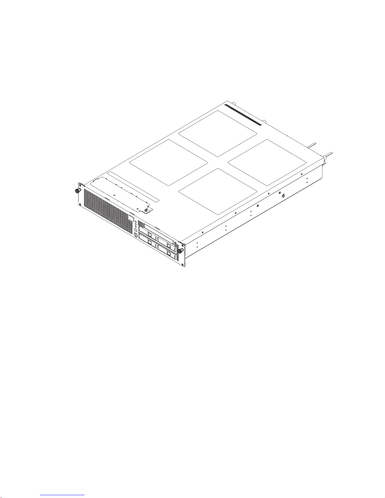
FIGURE 1-1 shows the external view of the M3000 server.
FIGURE 1-1 External View of the Server
The M3000 server has the following features:
■ Space-saving
The server has a 2 rack units (2U) enclosure, which realizes the space-saving and
the lightness in weight.
■ Energy-saving
Compared to our existing models, the M3000 server significantly improves the
energy consumption efficiency, and reduces the system power consumption to
500W (with 200 to 240 VAC).
■ Mounted high-performance processor adopting energy-saving technology
The SPARC64 VII+ or SPARC64 VII processors enhance the processing
performance and at the same time reduces the power consumption.
■ Improved cooling and power efficiency
The server is equipped with an air duct and a backflow prevention shutter unit
which optimize the airflow within the chassis and realize high cooling
efficiency. Moreover, the server uses power supply units with good power
efficiency, reducing power consumption.
1-2 SPARC Enterprise M3000 Server Overview Guide • March 2012
Page 13

■ Multiple-step fan speed control
The fan speeds are finely adjusted according to the altitude and the ambient
temperature at the installation site of the server. Such adjustments reduce
noise and realize quiet operation well suited for the office environment as well
as reducing power consumption.
■ High performance server enhanced with the latest architecture
■ SPARC64 VII+ or SPARC64 VII processors
The processors provide superior performance, with two or four cores each of
which can execute 2 threads. In addition, the Error Checking and Correction
(ECC) function and the instruction retry function provide high reliability and
high availability.
■ Power-saving by system LSI
By using the 65 nm process technology, system controller and memory access
controller have been packed on a single LSI (Large Scale Integration), which
realizes the power-saving.
■ Using PCI Express (PCIe) as an I/O bus
The PCIe bus having a band of up to eight lanes is used for the interconnect
bus with the I/O device.
■ High reliability and high availability
■ Data protection with the ECC function
ECC function protects data on all system buses and in memory, so that any
errors in data are automatically corrected. In addition to ECC, advanced ECC
memory protection is supported.
■ Redundant configuration and active/hot replacement of components
Hard disk drives, fan units, and power supply units support redundant
configuration and active/hot replacement. In a redundant configuration, the
system can be operated continuously even if one of the components fails.
Faulty components can be maintained/replaced without stopping the system.
■ Automatic reboot at component failure
If a failure occurs, the faulty component is automatically isolated from the
system, and the system is rebooted. If 1-bit errors occur frequently in the cache
memory configuring a CPU, the faulty memory can be dynamically isolated
without rebooting the Oracle Solaris Operating System (Oracle Solaris OS).
These degradation functions enable the business operation to be continued
based on non-faulty resources. The functions thus implement high faulttolerance even if a component fails.
Chapter 1 System Overview 1-3
Page 14

■ Uninterruptible Power Supply (UPS) controller
For measures against commercial power failure, the server is equipped with
UPS controller(UPC) ports. Using a UPS enables stable power supply to the
system when a power failure or an extensive power interruption occurs.
■ Hardware RAID function
Several hard disks which are connected to the on-board Serial Attached SCSI
(SAS) controller of the M3000 server can be constructed as a single logical
volume. The mirrored configuration of the constructed logical volume can
secure the data redundancy, as well as achieve the improvement in system
fault tolerance.
Note – Hardware RAID is available only on the M3000 server with the SPARC64
VII+ processors.
■ eXtended System Control Facility (XSCF)
The server is equipped with a service processor called eXtended System
Control Facility (XSCF), which monitors the system status including system
temperature, hardware status of the power supply units and fan units, and
operating status of the domain. There are two types of interfaces: browser
interface called XSCF Web and command-line interface called XSCF Shell.
When a power failure is detected, it is also possible to configure whether to
partially degrade the faulty component to continue system operation.
In addition, the schedule management function can be used to automatically
power the server on/off according to the specified operation schedule.
The console of the domain can be controlled by XSCF firmware via a network.
For the console control, prepare a terminal to display the console. The
following devices can be used as terminals:
- Personal computer (PC)
- Workstation
- ASCII terminal
- Terminal server (or patch panel connected to the terminal server)
For information on how to connect the console, see the SPARC Enterprise
M3000 Server Installation Guide.
■ Use of Oracle Solaris OS
The Oracle Solaris OS is widely used in the world. The Oracle Solaris 10 OS
used by the M3000 server has an enhanced process privilege management
function and network function, and is further equipped with superior
functions including Oracle Solaris Predictive Self-Healing that enables error
prediction and self-recovery.
1-4 SPARC Enterprise M3000 Server Overview Guide • March 2012
Page 15

1.2 System Specifications
TABLE 1-1 shows the specifications of the fully configured M3000 server. For details
on specifications of each component, see Section 1.4, “Components” on page 1-9. For
the specifications of the equipment rack, see the SPARC Enterprise Equipment Rack
Mounting Guide.
TABLE 1-1 Server Specifications
Item Specifications
Motherboard unit 1 unit
CPU Type: SPARC64 VII+ or SPARC64 VII processors
1 CPU (2 cores/4 cores)
Memory modules 8 modules
PCI Express (PCIe) slot 4 slots
eXtended System Control Facility unit (XSCF unit) 1 unit
Power supply unit 2 units (1+1 redundant configuration)
Fan unit 2 units (1+1 redundant configuration)
On-board drive 1 CD-RW/DVD-RW drive unit
4 hard disk drives
Domain 1 domain
Architecture Platform group: sun4u
Platform name: SUNW, SPARC-Enterprise
Mountable rack Equipment rack
Server dimensions (width x depth x height) 440 x 657 x 87 mm (2 rack units)
17.4 x 25.9 x 3.4 in.
*
Weight 22 kg (48.5 lb)
* The weight of cables are not included.
The environmental requirements listed in
TABLE 1-2 reflect the test results of the
server. The optimum conditions indicate the recommended operating environment.
Operating the server for extended periods at or near the operating range limits or
installing the server in an environment where it remains at or near the non-operating
range limits could possibly increase the failure rate of hardware components
significantly. In order to minimize the occurrence of system failure due to
component failure, set temperature and humidity in the optimal ranges.
Chapter 1 System Overview 1-5
Page 16

TABLE 1-2 Environmental Requirements
Operating Range Non-Operating Range Optimum
Ambient
temperature
Relative
humidity
*
Altitude
restriction
†
Temperature
conditions
5 °C to 35 °C
(41 °F to 95 °F)
Unpacked:
0 °C to 50 °C
21 °C to 23 °C
(70 °F to 74 °F)
(32 °F to 122 °F)
Packed:
-20 °C to 60 °C
(-4 °F to 140 °F)
20 % RH to 80 % RH to 93 % RH 45 % RH to 50 % RH
3,000 m (10,000 ft) 12,000 m (40,000 ft)
5 °C to 35 °C (41 °F to 95 °F):
0 m to 500 m (0 ft to 1,640 ft)
5 °C to 33 °C (41 °F to 91.4 °F):
501 m to 1,000 m (1,644 ft to 3,281 ft)
5 °C to 31 °C (41 °F to 87.8 °F):
1,001 m to 1,500 m (3,284 ft to 4,921 ft)
5 °C to 29 °C (41 °F to 84.2 °F):
1,501 m to 3,000 m (4,925 ft to 9,843 ft)
* There is no condensation regardless of the temperature and humidity.
† All altitudes are above sea level.
1-6 SPARC Enterprise M3000 Server Overview Guide • March 2012
Page 17
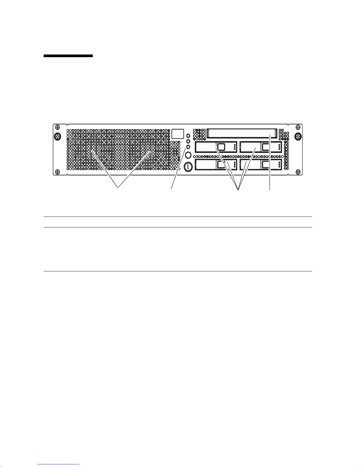
1.3 Component Names
12 34
FIGURE 1-2 and FIGURE 1-3 show the M3000 server components and list their names.
FIGURE 1-2 Front View of the Server
Location No. Component Maximum Number per Server
1 Fan unit (FAN_A) 2
2 Operator panel (OPNL) 1
3 Hard disk drive (HDD) (2.5-inch SAS disk) 4
4 CD-RW/DVD-RW drive unit (DVDU) 1
Chapter 1 System Overview 1-7
Page 18

FIGURE 1-3 Rear View of the Server (AC Power Supply Model)
123456 7
89
Location No. Component Maximum Number per Server
1 Power supply unit (PSU) 2
2PCIe slot 4
3RCI port
*
1
4 USB port (for XSCF) 1
5 Serial port (for XSCF) 1
6 LAN port (for XSCF) 2
7UPC port 2
8 Serial Attached SCSI (SAS) port 1
9 Gigabit Ethernet (GbE) port (for OS) 4
* For information on whether the RCI function is supported for your server, see the SPARC Enterprise
M3000/M4000/M5000/M8000/M9000 Servers Product Notes.
1-8 SPARC Enterprise M3000 Server Overview Guide • March 2012
Page 19

1.4 Components
This section explains the components of the M3000 server.
■ Motherboard Unit
■ Fan Unit
■ Power Supply Unit
■ Operator Panel
■ On-board Drive Units
■ I/O Port
TABLE 1-3 lists Field Replaceable Units (FRUs). For details of the replacement and
TABLE 1-3 Field Replaceable Units
expansion procedures, see the SPARC Enterprise M3000 Server Service Manual.
Components Redundant
Motherboard unit
No Yes
Cold
replacement
Hot
replacement
Active
replacement
Cold
expansion
Hot
expansion
Active
expansion
(MBU_A, MBU_A_2,
MBU_A_3, MBU_A_4,
MBU_A_5, MBU_A_6)
Memory (DIMM) No Yes Yes
PCIe card (PCIe) No Yes Yes
Hard disk drive (HDD) Yes
Hard disk drive
No Yes
*
Yes Yes Yes
†
Yes Yes Ye s
backplane (HDDBP)
CD-RW/DVD-RW drive
No Yes
unit (DVDU)
Power supply unit (PSU) Yes Yes Yes Yes
Fan unit (FAN_A) Yes Yes Yes Yes
Fan backplane
No Yes
(FANBP_B)
Operator panel (OPNL) No Yes
* The hard disk drive will have a redundant configuration by setting the mirroring.
† ■ If a hard disk drive is a nonmirrored boot device, it must be replaced according to the cold replacement procedure.
■ If a hard disk drive is in a mirrored configuration, active replacement can be performed on the failed drive because the mirrored hard
disk drive continues to be online and functioning. The hard disk replacement procedure varies by the mirroring configuration method.
†
Chapter 1 System Overview 1-9
Page 20

1.4.1 Motherboard Unit
The motherboard unit contains the main circuits of the M3000 server. The following
components are mounted on the unit.
■ CPU
■ Memory Slot
■ PCIe Slot
■ eXtended System Control Facility Unit (XSCF Unit)
■ DC-DC Converter
1-10 SPARC Enterprise M3000 Server Overview Guide • March 2012
Page 21

FIGURE 1-4 shows the motherboard unit and the components mounted on it.
1
2
3
4
5
FIGURE 1-4 Motherboard Unit
Location No. Component Maximum Number per Server
1CPU 1
2Memory slot 8
3PCIe slot 4
4 eXtended System Control Facility unit (XSCF unit) 1
5 DC-DC converter 4
Chapter 1 System Overview 1-11
Page 22

Note – The form of the DC-DC converter may be different depending on the
motherboard unit which is mounted.
To replace the CPU, the XSCF unit, and the DC-DC converters, you must replace the
motherboard unit.
To replace the motherboard unit, you must power the server off. For details, see the
SPARC Enterprise M3000 Server Service Manual.
1.4.1.1 CPU
The CPU is fixed to the motherboard unit. To replace the CPU, therefore, you must
replace the motherboard unit. For information on how to replace the motherboard
unit, see the SPARC Enterprise M3000 Server Service Manual.
1.4.1.2 Memory Slot
The M3000 server has eight memory slots. The server uses DDR2 SDRAM, as
mountable memory, that has the following functions:
■ Data protection by ECC
■ Recovery from memory chip failure
1-12 SPARC Enterprise M3000 Server Overview Guide • March 2012
Page 23

FIGURE 1-5 shows the memory slot locations.
1
FIGURE 1-5 Memory Slot Locations
Location No. Component Maximum Number per Server
1 Memory slot 8
For information on how to replace the memory module, see the SPARC Enterprise
M3000 Server Service Manual.
1.4.1.3 PCIe Slot
The M3000 server has four PCIe (x8 lanes) slots and supports low profile PCIe cards.
The PCIe features include a high-speed serial point-to-point interconnect. Compared
with PCI-X, the PCIe data transfer rates are doubled.
Chapter 1 System Overview 1-13
Page 24

FIGURE 1-6 shows the PCIe slot locations.
1
FIGURE 1-6 PCIe Slot Locations
Location No. Component Maximum Number per Server
1PCIe slot 4
For information on how to replace the PCIe card, see the SPARC Enterprise M3000
Server Service Manual.
1.4.1.4 eXtended System Control Facility Unit (XSCF Unit)
The eXtended System Control Facility unit (XSCF unit) contains the eXtended
System Control Facility (XSCF) that operates and controls the server. The XSCF
diagnoses and starts the server, controls the domain, and detects and notifies various
failures.
1-14 SPARC Enterprise M3000 Server Overview Guide • March 2012
Page 25

The XSCF unit provides the following interfaces to enable terminals such as personal
computers or workstations to connect to the XSCF. For the location and the number
of each port, see Section 1.3, “Component Names” on page 1-7.
■ Serial port
The system administrator can operate the server through the serial port. The
XSCF Shell can be used to set up and control the server.
■ LAN ports
The system administrator can operate the server remotely through the LAN ports.
The XSCF Shell or XSCF Web can be used to set up and control the server.
The following additional interfaces are also provided to control the system:
■ UPS controller (UPC) ports
An uninterruptible power supply (UPS) can be connected to the UPC port. Using
a UPS enables stable power supply to the system when a power failure or an
extensive power interruption occurs. This allows emergency shutdown
processing to be performed when a power failure is detected.
■ Remote Cabinet Interface (RCI) port
A peripheral device having an RCI connector is connected to the RCI port on the
server to enable power supply synchronization and error monitoring.
Note – For information on whether the RCI function is supported for your server,
see the SPARC Enterprise M3000/M4000/M5000/M8000/M9000 Servers Product Notes.
■ USB port
This USB port is dedicated for use by field engineers and cannot be connected to
general-purpose USB devices.
The XSCF unit is fixed to the motherboard unit. To replace the XSCF unit, therefore,
you must replace the motherboard unit. For information on how to replace the
motherboard unit, see the SPARC Enterprise M3000 Server Service Manual.
1.4.1.5 DC-DC Converter
The DC-DC converter is a component that converts DC input to another voltage
level.
To replace the DC-DC converter, you must replace the motherboard unit. For
information on how to replace the motherboard unit, see the SPARC Enterprise
M3000 Server Service Manual.
Chapter 1 System Overview 1-15
Page 26

1.4.2 Fan Unit
1
The fan unit generates airflow in the server to suppress temperature increases in the
server. The M3000 server uses 80 mm fan units for the cooling system.
The fan units are redundant, so system operation continues even if one fan unit fails.
If a fan unit fails during system operation, you can replace the faulty fan unit using
active/hot replacement procedures. The failure of the fan units can be detected by
the XSCF.
FIGURE 1-7 shows the fan unit locations.
FIGURE 1-7 Fan Unit Locations
Location No. Component Maximum Number per Server
1 Fan unit (FAN_A#0, FAN_A#1) 2
For information on how to replace the fan unit, see the SPARC Enterprise M3000
Server Service Manual.
1-16 SPARC Enterprise M3000 Server Overview Guide • March 2012
Page 27

1.4.3 Power Supply Unit
1
The power to the server is supplied through the power supply units.
The power supply units are redundant, so system operation continues even if one
power supply unit fails. If a power supply unit fails during system operation, you
can replace the faulty power supply unit using active/hot replacement procedures.
The failure of the power supply units can be detected by the XSCF.
FIGURE 1-8 shows the power supply unit locations.
FIGURE 1-8 Power Supply Unit Locations
Location No. Component Maximum Number per Server
1 Power supply unit (PSU#0, PSU#1) 2
Chapter 1 System Overview 1-17
Page 28

TABLE 1-4 lists the electrical specifications. For the other specifications, see the
SPARC Enterprise M3000 Server Site Planning Guide.
TABLE 1-4 Electrical Specifications
Item Specifications
Number of power cords
Redundancy
Input voltage
2 (one for each power supply unit)
1+1 redundant configuration
100 VAC to 120 VAC
200 VAC to 240 VAC
Rated current
*
4.80 A/5.15 A (100 VAC to 120 VAC)
2.59 A/2.81 A (200 VAC to 240 VAC)
Frequency
Power factor
†
50 Hz/60 Hz
0.98 (100 VAC to 120 VAC, full configuration)
0.89 (200 VAC to 240 VAC, full configuration)
* In a redundant configuration, the rated current per cable is half the value shown in
TABLE 1-4.
† This value applies to the full configuration.
For information on how to replace the power supply unit, see the SPARC Enterprise
M3000 Server Service Manual.
1-18 SPARC Enterprise M3000 Server Overview Guide • March 2012
Page 29

1.4.4 Operator Panel
1
2
3
4
5
The operator panel displays the system status, system problem alerts, and location of
system faults. It also stores system identification information and user setting
information. For details of the operator panel function, see the SPARC Enterprise
M3000 Server Service Manual.
FIGURE 1-9 shows the operator panel location.
FIGURE 1-9 Operator Panel Location
Location No. Component
1 POWER LED
2 XSCF STANDBY LED
3 CHECK LED
4POWER button
5 Mode switch (key switch)
Chapter 1 System Overview 1-19
Page 30

TABLE 1-5 and TABLE 1-6 list the states of the server displayed with the LEDs on the
operator panel and the switch functions.
TABLE 1-5 Switches (Operator Panel)
Switch Name Description of function
Mode
Switch
(Key
Switch)
Locked Normal operation mode
This switch is used to set the operation mode for the server.
Insert the special key that is under the customer's control, to
switch between modes.
• The system can be powered on with the power button, but
it cannot be powered off with the power button.
• The key can be pulled out at this key position.
Service Mode for maintenance
• The system can be powered on and off with the power
button.
• The key cannot be pulled out at this key position.
• To stop and maintain the server, set the mode to Service.
Power button This button is used to turn on or turn off the power to the
server (all domains).
Power on and power off are controlled by pressing this button
in different patterns, as described below.
Holding down the button
for a short time
(less than 4 seconds)
Holding down the button
for a long time in Service
mode
(4 seconds or longer)
Regardless of the mode switch setting, the server is powered
on.
If set in the XSCF, facility (air conditioners) power-on and
warm-up processing is skipped.
*
• If power to the server is on, OS shutdown processing is
executed for all domains before the system is powered off.
• If the server is being powered on, the power-on processing
is cancelled, and the server is powered off.
• If the server is being powered off, the operation of the
power button is ignored, and the power-off processing is
continued.
* In normal operation, the server is powered on only when the data center environmental conditions satisfy the specified values. Then,
the server remains in the reset state until the operating system is booted.
1-20 SPARC Enterprise M3000 Server Overview Guide • March 2012
Page 31

TABLE 1-6 LEDs on the Operator Panel
Icon Name Color Description
POWER LED Green Indicates the server power status.
• On: The power to the server (a domain) is on.
• Off: The power to the server is off.
• Blinking: The server is powered off.
XSCF
XSCF
STANDBY
LED
Green Indicates the XSCF unit status.
• On: XSCF unit is functioning normally.
• Off: Input power source is off or is just after turned on, and
XSCF unit is stopped.
• Blinking: System initialization is in progress after power
was turned on.
CHECK LED Amber Indicates that the server has detected an error. This is
sometimes called a locator.
• On: An error that hinders startup was detected.
• Off: Normal, or power is not being supplied.
• Blinking: Indicates that the unit is a maintenance target.
The operator panel displays the states of the server using combinations of three
LEDs in addition to the states listed in
TABLE 1-6. TABLE 1-7 lists the states that are
usually displayed in the course of operation from power-on to power-off of the
server.
TABLE 1-7 State Display by Combination of LEDs on the Operator Panel
Name Description
POWER
*
XSCF STANDBY CHECK
XSCF
Off Off Off Power is not being supplied.
Off Off On Power has been turned on.
Off Blinking Off The XSCF unit is being initialized.
Off Blinking On An error occurred in the XSCF unit.
Chapter 1 System Overview 1-21
Page 32

TABLE 1-7
Name Description
POWER
State Display by Combination of LEDs on the Operator Panel (Continued)
*
XSCF STANDBY CHECK
XSCF
Off On Off The XSCF unit is in the standby state.
The server is waiting for power-on of the air
conditioning facilities in the data center.
On On Off Warm-up standby processing is in progress (power is
turned on after the end of processing).
The power-on sequence is in progress.
The server is in operation.
Blinking On Off The power-off sequence is in progress.
(The fan units are stopped after the end of processing.)
* READY LED is referred to when the XSCF unit status is indicated.
Note – Some FRUs are equipped with status LEDs. For details of the status LEDs,
see the SPARC Enterprise M3000 Server Service Manual.
1-22 SPARC Enterprise M3000 Server Overview Guide • March 2012
Page 33

1.4.5 On-board Drive Units
1
2
The M3000 server contains the following on-board drives:
■ Hard Disk Drive
■ CD-RW/DVD-RW Drive Unit
FIGURE 1-10 shows the locations of the on-board drive units.
FIGURE 1-10 Locations of Hard Disk Drives and CD-RW/DVD-RW Drive Unit
Location No. Component Maximum Number per Server
1 Hard disk drive (HDD#0, HDD#1, HDD#2,
2 CD-RW/DVD-RW drive unit (DVDU) 1
4
HDD#3)
Chapter 1 System Overview 1-23
Page 34

1.4.5.1 Hard Disk Drive
1
2
The M3000 server uses the SAS interface to implement high-speed data transfer.
When connecting multiple hard disks, you can configure these hard disks as the
mirroring disks by the Hardware RAID or the software RAID.
For information on how to replace the hard disk drives, see the SPARC Enterprise
M3000 Server Service Manual.
1.4.5.2 CD-RW/DVD-RW Drive Unit
The M3000 server supports the DVD-ROM, DVD-R/DVD-RW, CD-ROM, and CDR/CD-RW formats and enables up to 8X read/write on DVD and up to 24X
read/write on CD.
For information on how to replace the CD-RW/DVD-RW drive unit, see the SPARC
Enterprise M3000 Server Service Manual.
There are two types of CD-RW/DVD-RW drive units: slot-loading type and trayloading type.
FIGURE 1-11 Types of CD-RW/DVD-RW Drive Unit
Location No. Component
1 Tray-loading CD-RW/DVD-RW drive unit
2 Slot-loading CD-RW/DVD-RW drive unit
Note – The locations of the LED and button might vary depending on the servers.
1-24 SPARC Enterprise M3000 Server Overview Guide • March 2012
Page 35

Note – When you use the medium on the tray-loading type CD-RW/DVD-RW drive
1
2
unit, make sure that the center of the medium is secured to the clamp of the tray, and
then push the tray into the drive.
1.4.6 I/O Port
The following interfaces are provided to connect the M3000 server to networks and a
external device:
■ GbE Port
■ SAS Port
FIGURE 1-12 shows the locations of the I/O ports.
FIGURE 1-12 I/O Ports Locations
Location No. Component Maximum Number per Server
1SAS port 1
2 GbE port (for Oracle Solaris OS) 4
1.4.6.1 GbE Port
The GbE ports connect the Oracle Solaris OS to networks. Because the ports support
the 1000BASE-T GbE connection, high-speed and high-capacity data transmission is
possible.
Chapter 1 System Overview 1-25
Page 36

1.4.6.2 SAS Port
The SAS port connects the server to an external device, such as a tape drive, which
has a SAS interface. For information on which devices can be connected, contact a
service engineer.
Note that the transfer rate of this port is up to 600 MB/s (3Gbps x 2wide).
Note – Even though the SAS port has four lanes, only two lanes can be used with
this port.
1-26 SPARC Enterprise M3000 Server Overview Guide • March 2012
Page 37

CHAPTER
2
System Functions
This chapter explains the following hardware and software functions of the M3000 server.
■ Section 2.1, “Hardware Configuration” on page 2-1
■ Section 2.2, “Domain” on page 2-3
■ Section 2.3, “Resource Management” on page 2-3
■ Section 2.4, “RAS” on page 2-4
■ Section 2.5, “Oracle Solaris Operating System” on page 2-6
■ Section 2.6, “XSCF Firmware” on page 2-7
2.1 Hardware Configuration
This section explains the hardware configuration, which includes the following topics:
■ CPU
■ Memory Subsystem
■ I/O Subsystem
■ System Bus
■ System Control
2.1.1 CPU
The M3000 server contains the multi-core SPARC64 VII+ or SPARC64 VII processors
that provide high performance. The SPARC64 VII+ and SPARC64 VII processors
contain on-chip large-capacity caches (primary and secondary caches) to minimize
memory latency. They also support an instruction retry function that enables
continuous processing by retrying instructions whenever any error is detected.
2-1
Page 38

2.1.2 Memory Subsystem
The memory subsystem controls memory access and cache memory. The M3000
server uses DDR2 SDRAMs and can contain up to eight memory modules. The
memory subsystem supports up to two-way memory interleaving for high-speed
memory access.
2.1.3 I/O Subsystem
The I/O subsystem controls data transfer with I/O devices.
The I/O subsystem of the M3000 server contains the following:
■ PCIe cards
PCIe (x8 lane) slots
■ I/O controller (IOC) chip, which is the bridge chip between the system bus and
the I/O bus
■ PCI Express switch connected to slots
■ SAS port
2.1.4 System Bus
The CPU, memory subsystem, and I/O subsystem are directly connected to
implement data transfer by using a high-speed broadband switch.
If a data error is detected in the CPU, memory access controller (MAC), or I/O
controller (IOC), the system bus agent corrects the data and then transfers it.
2.1.5 System Control
The M3000 server is controlled by the eXtended System Control Facility (XSCF). The
XSCF operates on a dedicated service processor, which operates independently from
the processor of the server. As long as the power is supplied to the server, the XSCF
constantly monitors the server even if the domain power is off.
For details, see Section 2.6, “XSCF Firmware” on page 2-7 and the SPARC Enterprise
M3000/M4000/M5000/M8000/M9000 Servers XSCF User’s Guide.
2-2 SPARC Enterprise M3000 Server Overview Guide • March 2012
Page 39

2.2 Domain
The function that divides one server into multiple independent systems is called
partitioning. The partitioning function enables arbitrary assignment of resources in
the server according to the job load or processing amount. Individual systems thus
divided are referred to as domains. Each domain runs on an independent Oracle
Solaris OS.
However, the M3000 server does not support the partitioning function and,
therefore, the server cannot be divided into multiple domains. All resources in the
server are allocated to a single domain that is preconfigured.
The basic hardware resource making up a domain is called the physical system
board (PSB). The physical units (CPU, memory, I/O) making up the PSB are
logically divided, and each divided configuration unit is called the extended system
board (XSB). The types of XSB include the XSB making up a PSB not logically
divided into multiple parts (Uni-XSB), and each XSB making up a PSB logically
divided into four parts (Quad-XSB).
The PSB mounted in the M3000 server has one Uni-XSB. Because the system is not
divided, there is only one domain.
For details on the domain, see the SPARC Enterprise
M3000/M4000/M5000/M8000/M9000 Servers Administration Guide.
2.3 Resource Management
This section explains the Oracle Solaris Zone function that supports reconfiguration
of domain resources during system operation.
The Oracle Solaris OS has a function called Oracle Solaris Zone, which divides
processing resources and allocates them to applications. The Oracle Solaris Zone
provides flexible resource allocation, which enables optimal resource management
with consideration given to the processing load.
In a domain, resources can be divided into sections called containers. The
processing sections are allocated to each application. The processing resources are
managed independently in each container. If a problem occurs in a container, the
container can be isolated so that it does not affect other containers.
Chapter 2 System Functions 2-3
Page 40

2.4 RAS
RAS means the functions related to Reliability, Availability, and Serviceability.
The RAS function minimizes the system downtime by providing error checking at
adequate locations, and centralized monitoring and control of error checking. It
further correctly determines faulty locations and enables replacement of faulty
components during operation to minimize the system downtime.
■ Reliability
■ Availability
■ Serviceability
2.4.1 Reliability
Reliability represents the length of time the server can operate normally without
failure.
Reliability is equally important to both hardware and software.
To improve quality, adequate components must be selected with consideration given
to the product service life and the required response in case of a failure. In
evaluations such as stress tests that check the service life, components and products
are inspected to determine whether they meet the target reliability levels.
Furthermore, software could have problems attributable not only to programming
errors by also to hardware faults. These factors need to be taken into consideration
to improve the reliability of the entire system.
The M3000 server provides the following functions to implement high reliability:
■ Periodic software diagnosis (host watchdog monitoring)
Cooperates with XSCF firmware to periodically check whether the software
including the Oracle Solaris OS is running in the domain.
■ Periodic memory patrol
Periodically performs memory patrol to detect memory software errors and stuckat faults, even in memory areas not normally used. Memory patrol prevents
faulty memory areas from being used by the OS or the application software and
thereby prevents the occurrence of system failures.
■ Status checking of components
Keeps checking the status of each component to detect signs of an imminent fault,
such as system down occurrences, and thereby prevents system failures.
2-4 SPARC Enterprise M3000 Server Overview Guide • March 2012
Page 41

2.4.2 Availability
Availability represents the ratio of time the server is accessible and usable. An
operating ratio is used as an index.
Hardware and software problems in the system cannot be eliminated completely. To
provide high availability, the system must be incorporated with mechanisms that
enable continuous system operation even if a failure occurs in hardware such as
components and devices, or in software such as the OS or business application
software.
The M3000 server provides the following functions to implement high availability:
■ Supports redundant configurations and active/hot replacement of power supply
units and fan units
■ Supports redundant configurations and active/hot replacement of hard disk
drives by RAID technology
■ Extends the range of automatic correction of temporary faults in memory, system
buses, and LSI internal data
■ Supports the enhanced retry function and degradation function for detected faults
■ Shortens the system downtime by using automatic system reboot
■ Shortens the time taken for system startup
■ Collects fault information by the XSCF, and provides preventive maintenance
using different types of warnings
■ Supports the advanced ECC in the memory subsystem, which enables single-bit
error correction to continue processing in response to continuous burst read
errors caused by memory device failures
■ Supports the memory patrol function implemented in hardware, that detects and
corrects memory errors without affecting software processing
In addition, combination with clustering software or operating management
software can implement higher availability.
2.4.3 Serviceability
Serviceability is characterized by how easily a server fault can be diagnosed, and
how quickly the server can be recovered from the fault or how easily the fault can be
corrected.
To implement high serviceability, it must be possible to easily determine the
components or devices that caused faults. Furthermore, to recover from failures, the
system must be able to determine the cause of the failures and isolate the faulty
Chapter 2 System Functions 2-5
Page 42

components, so that the field engineer can replace them with ease. In addition, it is
important to notify the system administrator or field engineer of the symptoms in an
easy-to-understand manner.
The M3000 server provides the following functions to implement high serviceability:
■ Status LEDs that are mounted on the operator panel, main replaceable
components, and components that support active/hot replacement
■ Remote monitoring of the server operating status and remote maintenance
function using XSCF
■ LED blinking function to indicate the maintenance target (CHECK LED, which is
also called the locator LED)
■ Notes and cautions marked on various label types for the system administrators
and field engineer
■ Automatic notification to report different types of faults to the system
administrator and field engineer
■ Centralized systematic monitoring, such as with SNMP, of complex systems such
as in the data center
2.5 Oracle Solaris Operating System
The M3000 server uses the Oracle Solaris OS. The Oracle Solaris OS has the
following features:
■ Long-cultivated reliability
■ Affinity that fully brings out hardware performance of the SPARC architecture
■ A variety of application software and middleware
■ Resource management with Oracle Solaris Zone using Oracle Solaris container
technology
■ Advanced system management in cooperation with XSCF
For information on the Oracle Solaris OS, refer to the documents on the following
URL:
http://www.oracle.com/technetwork/documentation/index.html
2-6 SPARC Enterprise M3000 Server Overview Guide • March 2012
Page 43

2.6 XSCF Firmware
The M3000 server uses the XSCF firmware to manage the system. The XSCF
firmware, which is preinstalled in the service processor on the XSCF unit before
shipment from the factory, enables you to configure, manage, and maintain system
components.
2.6.1 User Interfaces
The XSCF provides two types of user interfaces.
■ XSCF Shell
The XSCF Shell is a command-line interface used by connecting terminals such as
a personal computer and workstation to the server through a serial connection or
LAN connection.
In a serial connection, the shell commands supported by XSCF can be used by
connecting a terminal to the serial port on the server. In addition, the console
redirection function provided by XSCF allows the terminal to be used as an OS
console.
In a LAN connection, the shell commands supported by XSCF can be used by
connecting a terminal to XSCF through Secure Shell (SSH) or telnet.
■ XSCF Web
The XSCF Web is a browser interface used by connecting terminals to the server
through a LAN connection. The terminal is connected to XSCF using the browser
running on the terminal.
For details of how to connect and use the interfaces, see the following documents:
■ SPARC Enterprise M3000/M4000/M5000/M8000/M9000 Servers XSCF User’s Guide
■ SPARC Enterprise M3000/M4000/M5000/M8000/M9000 Servers XSCF Reference
Manual
■ SPARC Enterprise M3000/M4000/M5000/M8000/M9000 Servers Administration Guide
2.6.2 XSCF Functional Overview
The XSCF provides commands to manage the system platform, access control,
security, faults, logs, and domain.
Chapter 2 System Functions 2-7
Page 44

System management
The XSCF provides the following monitoring functions to increase system
availability:
■ Centralized control and monitoring of the server
■ Hardware configuration management and monitoring
■ Fan unit and power supply unit monitoring
■ System status monitoring
■ Fault monitoring
■ Domain status monitoring
■ Remote system monitoring through a LAN connection
■ Notification of faulty information to the system administrator
Security management
The XSCF provides the following functions to ensure system security:
■ User privilege management
Manages the privileges of user accounts used to operate XSCF. The XSCF
operation range of each user can be limited based on the user account types and
settings.
■ Access management by filtering
Provides the filtering function for permitting IP addresses used to access XSCF
and the encryption function based on SSH and SSL.
■ Log management
Stores the log data that can be used to investigate the causes of system errors
including operation failures and unauthorized accesses during system operation.
System status management
The XSCF provides the following functions to manage the system status:
■ Management of resources such as CPUs, memory, and I/O systems while the
Oracle Solaris OS is running
■ Management of errors and faults occurring in fan units and power supply units
Information on system operation and errors is stored as log data in XSCF. The log
data is used to analyze system problems. The system administrator, domain
administrator, and field engineer can access the log data.
2-8 SPARC Enterprise M3000 Server Overview Guide • March 2012
Page 45

Fault detection and management
The XSCF continuously monitors the status of the server for stable system operation,
and does the following if a fault is detected:
■ Prompt collection of fault information (hardware log)
■ Analysis of fault information
■ Identification of the faulty location
Hardware error and fault information are stored in XSCF. For information on the
error messages displayed and their explanations, see the SPARC Enterprise
M3000/M4000/M5000/M8000/M9000 Servers XSCF User’s Guide.
The XSCF degrades the faulty components to continue system operation or resets the
system to prevent another problem from occurring.
Remote control and monitoring of the system
The XSCF provides the following functions to enable remote management of the
server:
■ Remote system monitoring through a LAN connection
■ Notification of fault information to the system administrator
■ Remote console input/output
2.6.3 Airflow Indicator
The airflow indicator indicates the amount of air emitted from the server while the
M3000 server is up and running. To display the value, use the showenvironment
air command.
CODE EXAMPLE 2-1
XSCF> showenvironment air
Air Flow:63CMH
The value does not include the peripheral devices.
Note – The showenvironment air command displays the calculated airflow
based on the fan speed such as Low speed (level -1) or High speed (level -7) etc. The
fan speed is displayed by the showenvironment Fan command.
Chapter 2 System Functions 2-9
Page 46

For details of the showenvironment(8) command, refer to the man page. For
installation details of the SPARC Enterprise M3000 server, see the SPARC Enterprise
M3000 Server Site Planning Guide and the SPARC Enterprise M3000 Server Installation
Guide.
You can also obtain the exhaust air data using the SNMP agent function. To obtain
the data of exhaust air using the SNMP agent function, install the latest XSCF
extension MIB definition file to the SNMP manager. For details on the XSCF
extension MIB definition file, see the SPARC Enterprise
M3000/M4000/M5000/M8000/M9000 Servers XSCF User’s Guide.
2.6.4 Power Consumption Monitoring Function
The power consumption monitoring function confirms the amount of power
consumed while the SPARC Enterprise M3000 server is up and running.
To display the power consumption, use the showenvironment power command.
CODE EXAMPLE 2-2
XSCF> showenvironment power
Permitted AC power consumption:470W
Actual AC power consumption:450W
Note – The values displayed by the power consumption monitoring function are for
reference only. The power consumption value of the server varies by the conditions
such as the power supply in use, CPU types, or system configurations, or system
load.
For details of the showenvironment(8) command, see the man page. For
installation details of the SPARC Enterprise M3000 server, see the SPARC Enterprise
M3000 Server Site Planning Guide.
You can also obtain the power consumption data using the SNMP agent function. To
obtain the power consumption data using the SNMP agent function, install the latest
XSCF extension MIB definition file to the SNMP manager. For details on the XSCF
extension MIB definition file, see the SPARC Enterprise
M3000/M4000/M5000/M8000/M9000 Servers XSCF User’s Guide.
When there is a change in the power system, such as in the following occurrences,
wait for one minute, then check the value again.
■ During the server power-on or power-off, or after the power-on or power-off is
complete
2-10 SPARC Enterprise M3000 Server Overview Guide • March 2012
Page 47

■ During the active replacement of a power supply unit, or after the active
replacement is complete
Chapter 2 System Functions 2-11
Page 48

2-12 SPARC Enterprise M3000 Server Overview Guide • March 2012
Page 49

APPENDIX
A
DC Power Supply Model
This appendix describes the requirements specific to the DC power supply model.
Contact your sales representative for the DC power supply model.
To use the DC power supply model, make sure to read this information.
■ Section A.1, “The Server Views” on page A-2
This is equivalent to Section 1.3, “Component Names” on page 1-7. When using
the DC power supply model, refer to the content described in this appendix.
■ Section A.2, “Electrical Specifications” on page A-4
This is equivalent to
the content described in this appendix.
■ Section A.3, “Power Consumption Monitoring Function” on page A-5
This is equivalent to Section 2.6.4, “Power Consumption Monitoring Function” on
page 2-10. When using the DC power supply model, refer to the content described
in this appendix.
TABLE 1-4. When using the DC power supply model, refer to
Note – The content not mentioned in this appendix is common to the AC power
supply model and the DC power supply model. Refer to the description in each
chapter.
A-1
Page 50

A.1 The Server Views
12 34
This section describes the names of parts mounted on the DC power supply model.
Note – This is equivalent to Section 1.3, “Component Names” on page 1-7. When
using the DC power supply model, refer to the content described in this appendix.
FIGURE A-1 Front View of the Server
Location No. Component Maximum Number per Server
1 Fan unit (FAN_A) 2
2 Operator panel (OPNL) 1
3 Hard disk drive (HDD) (2.5-inch SAS disk) 4
4 CD-RW/DVD-RW drive unit (DVDU) 1
A-2 SPARC Enterprise M3000 Server Overview Guide • March 2012
Page 51

FIGURE A-2 Rear View of the Server (DC Power Supply Model)
12
34
56 7
89
Location No. Component Maximum Number per Server
1 Power supply unit (PSU) 2
2PCIe slot 4
3RCI port
*
1
4 USB port (for XSCF) 1
5 Serial port (for XSCF) 1
6 LAN port (for XSCF) 2
7UPC port 2
8 Serial Attached SCSI (SAS) port 1
9 Gigabit Ethernet (GbE) port (for OS) 4
* For information on whether the RCI function is supported for your server, see the SPARC Enterprise
M3000/M4000/M5000/M8000/M9000 Servers Product Notes.
Appendix A DC Power Supply Model A-3
Page 52

A.2 Electrical Specifications
This section describes the electrical specifications of the DC power supply model.
Note – This is equivalent to TABLE 1-4. When using the DC power supply model,
refer to the content described in this appendix.
TABLE A-1 Electrical Specifications
Item Specifications
Number of power cords
Redundancy
Input voltage
Rated current
* In a redundant configuration, the rated current per cable is half the value shown in TA BLE A-1.
*
2 (one for each power supply unit)
1 + 1 redundant configuration
-48 Vdc -60 Vdc
10.52 A 8.50 A
A-4 SPARC Enterprise M3000 Server Overview Guide • March 2012
Page 53

A.3 Power Consumption Monitoring
Function
This section describes the Power Consumption Monitoring Function of the DC
power supply model.
Note – This is equivalent to Section 2.6.4, “Power Consumption Monitoring
Function” on page 2-10. When using the DC power supply model, refer to the
content described in this appendix.
The power consumption monitoring function confirms the amount of power
consumed while the SPARC Enterprise M3000 server is up and running.
To display the power consumption, use the showenvironment power command.
CODE EXAMPLE A-1
XSCF> showenvironment power
Permitted DC power consumption:470W
Actual DC power consumption:450W
Note – The values displayed by the power consumption monitoring function are for
reference only. The power consumption value of the server varies by the conditions
such as the power supply in use, CPU types, or system configurations, or system
load.
For details of the showenvironment(8) command, see the man page. For
installation details of the SPARC Enterprise M3000 server from Oracle and Fujitsu,
see the SPARC Enterprise M3000 Server Site Planning Guide.
You can also obtain the power consumption data using the SNMP agent function. To
obtain the power consumption data using the SNMP agent function, install the latest
XSCF extension MIB definition file to the SNMP manager. For details on the XSCF
extension MIB definition file, see the SPARC Enterprise
M3000/M4000/M5000/M8000/M9000 Servers XSCF User’s Guide.
When there is a change in the power system, such as in the following occurrences,
wait for one minute, then check the value again.
Appendix A DC Power Supply Model A-5
Page 54

■ During the server power-on or power-off, or after the power-on or power-off is
complete
■ During the active replacement of a power supply unit, or after the active
replacement is complete
A-6 SPARC Enterprise M3000 Server Overview Guide • March 2012
Page 55

Index
A
airflow indicator, 2-9
architecture, 1-5
availability, 2-5
C
CD-RW/DVD-RW drive unit, 1-24
components, 1-9
cooling, 1-16
CPU, 1-12
D
DC-DC converter, 1-15
DDR2 SDRAM, 1-12
DIMM, 1-12
domain, 2-3
E
environmental conditions, 1-6
eXtended System Control Facility Unit (XSCFU), 1-
14, 2-2
eXtended System Control Facility (XSCF), 2-7
function, 2-7
user interface, 2-7
external dimensions, 1-5
F
fan, 1-16
field replaceable units (FRU), 1-9
H
hard disk drive, 1-24
hardware configuration
CPU, 2-1
I/O subsystem, 2-2
memory subsystem, 2-2
system bus, 2-2
system control, 2-2
Hardware RAID, 1-4, 1-24
M
memory, 1-12
memory slot, 1-12
motherboard unit, 1-10
O
on-board drive, 1-23
CD-RW/DVD-RW drive unit, 1-24
hard disk drive, 1-24
operating system, 2-6
operator panel, 1-19
Oracle Solaris operating system, 2-6
Oracle Solaris Zone, 2-3
P
PCIe card, 2-2, 1-13
PCIe slot, 2-2, 1-13
Power Consumption Monitoring Function, 2-10
power supply unit, 1-17
Index-1
Page 56

R
rack, 1-5
RAS, 2-4
reliability, 2-4
reliability, availability, serviceability (RAS), 2-4
resource management, 2-3
S
service processor, 1-14
serviceability, 2-5
SPARC64 VII processor, 1-1, 1-3
SPARC64 VII+ processor, 1-1, 1-3
specifications, 1-5
switch, 1-20
system
component names, 1-7, A-2
components, 1-9
features, 1-2
specifications, 1-5
U
UPS, A-1
UPS Controller, A-1
W
weight, 1-5
X
XSCF firmware, 2-7
function, 2-7
user interface, 2-7
XSCF unit, 2-2, 1-14
Index-2 SPARC Enterprise M3000 Server Overview Guide • March 2012
 Loading...